2.1-2.44(angular) 2.1 …fixtools.com.ar/pdf/destaco/grippers/grippers angulares.pdf · food...
TRANSCRIPT
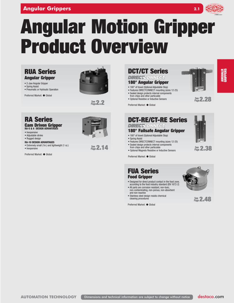
DCT-RE/CT-RE Series180° Failsafe Angular Gripper• 180° of travel (Optional Adjustable Stop)• Spring Assist• Features DIRECTCONNECT mounting (sizes 12-25)• Sealed design protects internal components from chips and other particulate
• Optional Magneto Resistive or Inductive Sensors
Preferred Market: l Global
DCT/CT Series180° Angular Gripper• 180° of travel (Optional Adjustable Stop)• Features DIRECTCONNECT mounting (sizes 12-25)• Sealed design protects internal components from chips and other particulate
• Optional Resistive or Inductive Sensors
Preferred Market: l Global
SeePage2.28
SeePage2.38
Angular Motion GripperProduct Overview
TM
TM
SeePage2.2
RA SeriesCam Driven GripperRA-5 & 6 DESIGN ADVANTAGES• Inexpensive• Adjustable stroke• Rugged designRA-10 DESIGN ADVANTAGES• Extremely small (1in.) and lightweight (1 oz.)• Inexpensive
Preferred Market: l Global
SeePage2.14
FUA SeriesFood Gripper• Designed for direct product contact in the food zone, according to the food industry standard (EN 1672-2)
• All parts are corrosion resistant, non-toxic, non-contaminating, non-porous, non-absorbent and non-reactive
• Stainless steel design resists chemical cleaning procedures
Preferred Market: l Global
SeePage2.48
RUA SeriesAngular Gripper • 2-Jaw Angular Gripper• Spring Assist• Pneumatic or Hydraulic Operation
Preferred Market: l Global
ANGUALR
GRIPPERS
Angular Grippers
destaco.com
2. 1
AUTOMATION TECHNOLOGY Dimensions and technical information are subject to change without notice
2.1-2.44�(Angular)_�2.1-2.32�(Angular).qx4��7/23/14��11:16�AM��Page�1

RUA SERIES
Angular Grippers
destaco.com
2.2
AUTOMATION TECHNOLOGYDimensions and technical information are subject to change without notice
Grippers can be mounted & operated in any orientation
Mounting Information:
RUA Spring Assist 2-Jaw AngularGrippers• Cost effective:The simplified drive mechanism makes these grippers an excellent value
• Compact, robust & powerful gripper:This gripper is designed for use in confined spaces, combining large opening angle with a high torque. Optional safety springs retain the components, should the air supply fail or to increase grip force
• Multipurpose gripper:A wide range of options and accessories (hydraulic or pneumatic operation, safetysprings for internal or external clamping, Viton® seals, and magneto resistive orinductive sensing) allow these grippers to be used in a number of applications
• Harsh environment:Shielded design repels chips and other particulate from internal drive mechanism
• High Temperature Design (Vulcan Series):Designed for heavy-duty, extreme high temperature applications, the Vulcan Series Gripper can be ordered with optional metal seals and fireproof kevlar boot or stainless steel heat shield for added protection
Specifications Imperial MetricPneumatic Pressure Operating Range:Standard 30-100 psi 2-7 barwith -RE, -RI Spring Option 45-100 psi 3-7 bar
Hydraulic Pressure Operating Range:**Hydraulic 30-290 psi 2-20 barwith -RE, -RI Spring Option 45-290 psi 3-20 bar
Cylinder Type Double Actingor Single Acting Spring Returnor Double Acting Spring Assist
Dynamic Seals Internally Lubricated Buna-NValve Required 4-way, 2-position for Double Acting to Operate or 3-way, 2-position for Single ActingAir Quality RequirementsAir Filtration 40 Micron or BetterAir Lubrication Not Necessary*Air Humidity Low Moisture Content (dry)Temperature Operating RangeViton® Seals (RUA Series) -20°~300° F -30°~150° CVulcan Series -20°~842° F -30°~450° CMaintenance Specifications†Expected Life Normal Application 5 million cyclesw/ Preventative Maintenance 10+ million cycles*
Field Repairable YesSeal Repair Kits Available Yes*Addition of lubrication will greatly increase service life† See Maintenance Section** The gripper can be operated at 290psi (20 bars) MAXIMUM hydraulic pressure. Cycle timesare longer and may depend on the hydraulic system. Grippers must be mounted beforebeing operated under hydraulic pressure. Please contact factory for more information.
Technical Specifications:
G
Gripper can be operated utilizing topmanifold air ports.
Fingers are located on jaws with 2 dowel pinsand assembled with 1 screw.
Gripper is located using pilotboss and a dowel pin andassembled with 4 through
body screws.
2.1-2.44�(Angular)_�2.1-2.32�(Angular).qx4��7/23/14��11:16�AM��Page�2

RUA SERIES
Angular Grippers
destaco.com
2. 3
AUTOMATION TECHNOLOGY Dimensions and technical information are subject to change without notice
Product Features
Operating Principle
SeePage 2.4
Style -RUA Angular GripperSize -62M Style: RUA-62M
Stroke: 33.6° Grip Force:* 86 lbs 384 N Weight: 0.86 lbs 0.39 Kg
- A double acting piston, connected to a cam driver with a groove, drives thecams levers.
- The piston’s translatory motion makes the cams levers rotate in a synchronous motion.
- Optional springs can be used to increase the grip force, to hold part in theevent of loss of air, or to use the gripper in single acting mode.
- This gripper is suitable for internal or external gripping.
Body
Pivot Pin
Cam DriverGroove
Cam Lever
Cap
Shielded Case
Spring
Piston
Jaw
Exhaust
Pressure
Pressure
Exhaust
Multiple PortsSide or top
manifold ports
HydraulicOperation
Optional hydraulicseals for 290 psi [20 bar] Max. operation
Safety SpringsOptional springs retain the component,should the air supply fail, to assist
the gripper for internal (-RI) or external(-RE) gripping, or in single acting or
spring assist mode
Hi-Temp Design
Designed for extreme high temperature applications up to 842°F [450°C]
(Vulcan Series only)
Magneto Resistive Sensing
The gripper comes with adjustableslots for 2 magnetic sensors.
(to control jaw position). Must be used with -RE or -RI option.(Except sizes 142M & 162M)
Quality ComponentsMade of Aluminum alloy, hard coatanodized with Teflon Impregnation.The gripper’s main components are
made of heat treated steel.
Integrated Inductive Sensor An integrated sensor
(KT1 or KT2 option) allows tosense jaws in open or
closed position
Viton® SealsStandard Viton® seals for high temperatures (-20°F to +300°F / -30°~150° C)
Shielded Case and CoversGripper is shielded
to repel chips and otherparticulate from internal
drive mechanism.
Gripper AttachmentFrom the top or from the back using
DirectConnect pattern(except sizes 142M & 162M).
SeePage 2.6
Style -RUA Angular GripperSize -82M Style: RUA-82M
Stroke: 31.8° Grip Force:* 276 lbs 1228 N Weight: 1.54 lbs 0.70 Kg
*Grip force @ 100PSI [7 bar], L=1" [25.4], with spring, jaws at 0º
*Grip force @ 100PSI [7 bar], L=1" [25.4], with spring, jaws at 0º
SeePage 2.8
Style -RUA Angular GripperSize -112M Style: RUA-112M
Stroke: 38.2° Grip Force:* 483 lbs 2150 N Weight: 3.75 lbs 1.70 Kg
*Grip force @ 100PSI [7 bar], L=1" [25.4], with spring, jaws at 0º
SeePage 2.10
Style -RUA Angular GripperSize -142M Style: RUA-142M
Stroke: 35.2° Grip Force:* 1298 lbs 5775 N Weight: 9.05 lbs 4.1 Kg
*Grip force @ 100PSI [7 bar], L=1" [25.4], with spring, jaws at 0º
Style -RUA Angular GripperSize -162M Style: RUA-162M
Stroke: 34.4°Grip Force:* 1778 lbs 7911 N Weight: 14.80 lbs 6.7 Kg
*Grip force @ 100PSI [7 bar], L=1" [25.4], with spring, jaws at 0º
SeePage 2.12
2.1-2.44�(Angular)_�2.1-2.32�(Angular).qx4��7/23/14��11:16�AM��Page�3

RUA SERIES
Angular Grippers
destaco.com
2.4
AUTOMATION TECHNOLOGYDimensions and technical information are subject to change without notice
RUA-62M Product Specifications
20°
20°
20°
45°
40°
40°
30°
Same attachmentas gripper
Inductive sensor
2.99276.0
2.79571.0
Opened: 13°
Closed: 3.9°
[ M5 x 7 DP]
[3 h7]Ø 0.1181 SF
Close
Open
0.51213.0
0.511813.00
0.74819.0
0.3937[10 f8]
[50.8]
Close
[4.5]
Ø 2.000
4 x Ø 0.177
Ø 0.1969 SF x 0.512Open
[ 5 H9 x 13 DP]Purge port
Manifold air portSupplied plugged
2 [G1/8 x 5 DP]
Purge / Scavenge port [ M5 x 6 ]
CL h7 ]38.1[
0.84621.5
16.0
2.6
60.0
0.102
1.89048.0
53.0
0.236
2.087
6.0
35.0
0.394
1.378Ø 1.5000 SF
3.0
2.362
0.118
0.94524.0
10.00.630
Ø
1.47637.5
-KT: Inductive sensor
Yellow LED Green LED
KT1 0° to 3.4° 13.4° to 16.8°
KT2 0° to 6.8° 10° to 16.8°
Sensing range(From close position)
Third Angle Projection
Dimensions are symmetrical about
centerline
Imperial in. Metric [mm]0.00 = ±.01 [0.] = [±.25]0.000 = ±.005 [0.0] = [±.13]0.0000 = ±.0005 [0.00] = [±.013]
All Dowel Holes are SF (Slip Fit). Locational Tolerance
±.0005" or [±.013mm]
UNLESS OTHERWISE NOTED ALL TOLERANCES ARE AS SHOWN BELOW
Metric ThreadsCourse Pitch
How to Order: (Order Separately)
POWER P PneumaticH Hydraulic (20 bar max.)
SPRING RE ClosedRI Open__ Leave Blank. No Spring Option (standard)
INDUCTIVE CASE* KT1 Sensing Range KT1KT2 Sensing Range KT2__ Leave Blank. No Inductive Option
SENSOR ACCESSORIES ORDER # QTY/UNIT
PNP Magneto Resistive Sensor w/Qk Disconnect* ** †† OHSP-017 1 or 2NPN Magneto Resistive Sensor w/Qk Disconnect* ** †† OHSN-017 1 or 2PNP Magneto Resistive Sensor (90° Barrel) w/Qk Disc* ** †† OHSP-011 1 or 2NPN Magneto Resistive Sensor (90° Barrel) w/Qk Disc* ** †† OHSN-011 1 or 2Replacement PNP Double Inductive Sensor* *** KT15 1Quick Disconnect 2 Meter Cable* CABL-010 1 or 2Quick Disconnect 5 Meter Cable* CABL-013 1 or 2Quick Disconnect 2 Meter Cable (for KT15 Inductive Sensor)* CABL-014 1 or 2
SEALED BOOT KITSPVC Sealed Jaw Boot Kit (includes 2 interfaces, 1 collar, 1 boot) SLKT-367 1Kevlar Sealed Jaw Boot Kit (includes 2 interfaces, 1 collar, 1 boot) SLKT-368 1FireProof Kevlar Sealed Jaw Boot Kit (includes 2 interfaces, 1 collar, 1 boot) SLKT-369 1
SEAL REPAIR KIT PNEUMATIC HYDRAULIC
Viton® Seal Repair Kit SLKT-156V SLKT-330V 1
*Sensor and cable sold separately †Requires Mounting Kit **Piston magnet standard ††Not compatible with Hydraulic (-H) option and requires -RE or -0RI option***Requires KT1 or KT2 Inductive Case Option
SAMPLE ORDER: RUA-62M-P-RI-KT1Ex: RUA-62M Gripper, Pneumatic, Spring Open, Sensing Range KT1
RUA-62M - - -INTEGRATED SENSOR
BASIC MODEL SPRING ASSIST (See Below)
P-PneumaticH-Hydraulic
POWER
2.1-2.44�(Angular)_�2.1-2.32�(Angular).qx4��7/23/14��11:16�AM��Page�4

RUA SERIES
Angular Grippers
destaco.com
2. 5
AUTOMATION TECHNOLOGY Dimensions and technical information are subject to change without notice
RUA-62M Product Specifications
ZZ
Mx My
X
F/2 F/2
Y
C T
L
0
56
112
169
225
281
337
0
250
500
750
1000
1250
1500
0.5 1.0 1.5 2.0 2.5 3.0 3.5 in.12.7 25.4 38.1 50.8 63.5 76.2 88.9 mm
EFFECTIVE FINGER LENGTH FROM ROTATION AXIS - L
FING
ER F
ORCE
- F
/2
WARNING!DO NOT EXCEED
MAXIMUM EFFECTIVE FINGER LENGTHS
GRIP FORCE PER FINGER (at 0° with Spring Assist)
0 PSI [0 bar]
60 PSI [4.1 bar]
80 PSI [5.5 bar]
100 PSI [7 bar]
290 PSI [ 20 bar]
lbs.N
Specifications RUA-62MTotal Rated Grip Force L=1 in [25.4mm] @ 0°100 psi, 7 bar, w/spring................................ 86 lbs. 384 N100 psi, 7 bar, w/o spring ............................ 70 lbs. 313 N
Stroke................................................................ 16.8° of stroke for each fingerWeight .............................................................. 0.86 lbs. 0.39 kgPressure Range (without springs) .................... 30-100 psi 2-7 barPressure Range (with springs) ......................... 45-100 psi 3-7 barCylinder Bore Ø ................................................ 1.57 in. 40 mmDisplacement ................................................... 0.73 in3. 12 cm3
Temperature RangeViton® Seals Standard .................................. -20°~300° F -30~150° C
Actuation (open/close)..................................... 0.18 sec./0.18 sec.Accuracy........................................................... ±0.002 in. ±0.05 mmRepeatability..................................................... ±0.0008 mm. ±0.02 mmValve required to actuate single acting ............ 3-way, 2-positionValve required to actuate double acting........... 4-way, 2-position
Accessory Mounting Technical Data
Boot• Protects the gripper mechanism• Provides better performance and longer life time in harsh environment
• Three materials available depending on the application:– PVC for grinding applications (up to 176°F / 80°C)
– Kevlar for machine applications (up to 480°F / 250°C)
– Fireproof Kevlar for welding applications (up to 525°F / 275°C)
• A provided spacer has to be added to the jaws
Plumbing Fittings• Adjustable flow controls:– Have thumb screw adjust with lockingnut for adjusting actuation time
– Available for 6mm OD tubing• Plumbing fittings: • For side air port location• Top airport are plugged as standard
MR Sensors• PNP and NPN Magneto Resistive available• Sensors are slot mounted, no mounting kits required• Simple adjustment with slotted screw driver• Built in LED for ease of positioning and troubleshooting• Available with 2M or 5M Quick Disconnect mating cable (order separately)
Loading Capacity† Static Dynamic
Maximum Tensile T 53 lbs. [236 N] 11 lbs. [47.2 N] Maximum Compressive C 53 lbs. [236 N] 11 lbs. [47.2 N]Maximum Moment Mx 111 in.-lbs. [12.5 Nm] 27 in.-lbs. [3.1 Nm]Maximum Moment My 305 in.-lbs. [34.5 Nm] 31 in.-lbs. [3.5 Nm]Maximum Moment Mz 111 in.-lbs. [12.5 Nm] 27 in.-lbs. [3.1 Nm]†Capacities are per set of jaws and are not simultaneous
OHSP/N 017
OHSP/N 0110.117 3
4.70.185
18.20.715.73 19
0.728 18.5
CONTROL G1/8VLVF-005
ADJUSTABLE FLOWPLUMBING FITTINGPLFT-038
1.212 30.8
0.51 13
54.32.138
Ø 833.268
0.445 11.3
ClampingCrown
Adapter platefor cover set up
2.1-2.44�(Angular)_�2.1-2.32�(Angular).qx4��7/23/14��11:16�AM��Page�5

RUA SERIES
Angular Grippers
destaco.com
2.6
AUTOMATION TECHNOLOGYDimensions and technical information are subject to change without notice
RUA-82M Product Specifications
15°
15°
1.22031.0
20°40°
45°
40°
30°
-KT: Inductive sensor
CL
2 [G1/8 x 5 DP]
Purge / Scavenge port [ M5 x 6 ] 50.8[
21.0
h7 ]
0.827
0.2767.0
0.59115.0
2.24457.0
1.96950.0
1.29933.0
3.15080.0
3.00.118
SF2.0000
16.00.630
3.10.122
1.45737.0
Closed: 2.9°
Opened: 13°
OpenØ 0.1969 SF x 0.512
4 x Ø0.209
Close
[69.9]Ø 2.750
[5.3]
[ 5 H9 x 13 DP]Purge port
Manifold air portSupplied plugged
Same attachmentas gripper
Inductive sensor
3.07178.0
3.34685.0
[ M6 x 12 DP]
CL
[4 h7]Ø 0.1575 SF
Close
Open
0.59115.0
f8]13[
29.01.142
0.787420.00
0.5118
Yellow LED Green LED
KT1 0° to 2.4° 13.5° to 15.9°
KT2 0° to 4.8° 11.1° to 19.9°
Sensing range(F rom close position)
How to Order: (Order Separately)
POWER P PneumaticH Hydraulic (20 bar max.)
SPRING RE ClosedRI Open__ Leave Blank. No Spring Option (standard)
INDUCTIVE CASE* KT1 Sensing Range KT1KT2 Sensing Range KT2__ Leave Blank. No Inductive Option
SENSOR ACCESSORIES ORDER # QTY/UNIT
PNP Magneto Resistive Sensor w/Qk Disconnect* ** †† OHSP-017 1 or 2NPN Magneto Resistive Sensor w/Qk Disconnect* ** †† OHSN-017 1 or 2PNP Magneto Resistive Sensor (90° Barrel) w/Qk Disc* ** †† OHSP-011 1 or 2NPN Magneto Resistive Sensor (90° Barrel) w/Qk Disc* ** †† OHSN-011 1 or 2Replacement PNP Double Inductive Sensor* *** KT15 1Quick Disconnect 2 Meter Cable* CABL-010 1 or 2Quick Disconnect 5 Meter Cable* CABL-013 1 or 2Quick Disconnect 2 Meter Cable (for KT15 Inductive Sensor)* CABL-014 1 or 2
SEALED BOOT KITSPVC Sealed Jaw Boot Kit (includes 2 interfaces, 1 collar, 1 boot) SLKT-370 1Kevlar Sealed Jaw Boot Kit (includes 2 interfaces, 1 collar, 1 boot) SLKT-371 1FireProof Kevlar Sealed Jaw Boot Kit (includes 2 interfaces, 1 collar, 1 boot) SLKT-372 1
SEAL REPAIR KIT PNEUMATIC HYDRAULIC
Viton® Seal Repair Kit SLKT-157V SLKT-331V 1
*Sensor and cable sold separately †Requires Mounting Kit **Piston magnet standard ††Not compatible with Hydraulic (-H) option and requires -RE or -0RI option***Requires KT1 or KT2 Inductive Case Option
SAMPLE ORDER: RUA-82M-H-RE-KT2Ex: RUA-82M Gripper, Hydraulic, Spring Closed, Sensing Range KT2
Third Angle Projection
Dimensions are symmetrical about
centerline
Imperial in. Metric [mm]0.00 = ±.01 [0.] = [±.25]0.000 = ±.005 [0.0] = [±.13]0.0000 = ±.0005 [0.00] = [±.013]
All Dowel Holes are SF (Slip Fit). Locational Tolerance
±.0005" or [±.013mm]
UNLESS OTHERWISE NOTED ALL TOLERANCES ARE AS SHOWN BELOW
Metric ThreadsCourse Pitch
RUA-82M - - -INTEGRATED SENSOR
BASIC MODEL SPRING ASSIST (See Below)
P-PneumaticH-Hydraulic
POWER
2.1-2.44�(Angular)_�2.1-2.32�(Angular).qx4��7/23/14��11:16�AM��Page�6

RUA SERIES
Angular Grippers
destaco.com
2. 7
AUTOMATION TECHNOLOGY Dimensions and technical information are subject to change without notice
RUA-82M Product Specifications
ZZ
Mx My
X
F/2 F/2
Y
C T
L
Accessory Mounting Technical Data
Loading Capacity† Static Dynamic
Maximum Tensile T 65 lbs. [290 N] 13 lbs. [58 N] Maximum Compressive C 65 lbs. [290 N] 13 lbs. [58 N]Maximum Moment Mx 168 in.-lbs. [19 Nm] 42 in.-lbs. [4.8 Nm]Maximum Moment My 1071 in.-lbs. [121 Nm] 106 in.-lbs. [12 Nm]Maximum Moment Mz 168 in.-lbs. [19 Nm] 42 in.-lbs. [4.8 Nm]†Capacities are per set of jaws and are not simultaneous
Specifications RUA-82MTotal Rated Grip Force L=1 in [25.4mm] @ 0°100 psi, 7 bar, w/spring................................ 276 lbs 1228 N100 psi, 7 bar, w/o spring ............................ 207 lbs. 922 N
Stroke .............................................................. 15.9° of stroke for each fingerWeight .............................................................. 1.55 lbs. 0.70 kgPressure Range (without springs) .................... 30-100 psi 2-7 barPressure Range (with springs) ......................... 45-100 psi 3-7 barCylinder Bore Ø ................................................ 2.36 in. 60 mmDisplacement ................................................... 2.14 in3. 35 cm3
Temperature RangeViton® Seals Standard .................................. -20°~300° F -30~150° C
Actuation (open/close)..................................... 0.10 sec./0.10 sec.Accuracy........................................................... ±0.002 in. ±0.05 mmRepeatability..................................................... ±0.0008 mm. ±0.02 mmValve required to actuate single acting ............ 3-way, 2-positionValve required to actuate double acting........... 4-way, 2-position
Plumbing Fittings• Adjustable flow controls:– Have thumb screw adjust with lockingnut for adjusting actuation time
– Available for 6mm OD tubing• Plumbing fittings: • For side air port location• Top airport are plugged as standard
MR Sensors• PNP and NPN Magneto Resistive available• Sensors are slot mounted, no mounting kits required• Simple adjustment with slotted screw driver• Built in LED for ease of positioning and troubleshooting• Available with 2M or 5M Quick Disconnect mating cable (order separately)
OHSP/N 017
OHSP/N 011
0.715 18.2
0.185 4.7
0.115 2.9
.73 19
0.728 18.5
CONTROL G1/8VLVF-005
ADJUSTABLE FLOWPLUMBING FITTINGPLFT-038
1.212 30.8
0.51 13
Adapter platefor cover set up
2.295
0.642 16.3
58.3
4.055 103
ClampingCrown
Boot• Protects the gripper mechanism• Provides better performance and longer life time in harsh environment
• Three materials available depending on the application:– PVC for grinding applications (up to 176°F / 80°C)
– Kevlar for machine applications (up to 480°F / 250°C)
– Fireproof Kevlar for welding applications (up to 525°F / 275°C)
• A provided spacer has to be added to the jaws
0
500
1000
1500
2000
2500
0
112
225
337
449
562
1.0 1.5 2.0 2.5 3.0 3.5 4.0 5.025.4
4.538.1 50.8 63.5 76.2 88.9 101.6 114.3 127
0 PSI [0 bar]
60 PSI [4.1 bar]
80 PSI [5.5 bar]
100 PSI [7 bar]
290 PSI [ 20 bar]
in.mm
lbs.N
EFFECTIVE FINGER LENGTH FROM ROTATION AXIS - L
FING
ER F
ORCE
- F
/2
WARNING!DO NOT EXCEED
MAXIMUM EFFECTIVE FINGER LENGTHS
GRIP FORCE PER FINGER (at 0° with Spring Assist)
2.1-2.44�(Angular)_�2.1-2.32�(Angular).qx4��7/23/14��11:16�AM��Page�7

RUA SERIES
Angular Grippers
destaco.com
2.8
AUTOMATION TECHNOLOGYDimensions and technical information are subject to change without notice
RUA-112M Product Specifications
15°
15°
40°
45°
40°
30°
20°
-KT: Inductive sensor
Opened: 13°
Closed: 6.2°
[ M8 x 13 DP]
Open
Close
[5 h7]Ø 0.1969 SF
CL
0.87022.1
1.000025.40
1.51238.4
0.7480[19 f8]
Ø 0.3150 SF x 0.512Open
Close
Ø 3.750 [95.3]
4 x Ø 0.335 [8.5]
Manifold air portSupplied plugged
[ 8 H9 x 13 DP]Purge port
Same attachmentas gripper
Inductive sensor
4.016102.0
4.370111.0
2 [G1/8 x 8 DP]
Purge / Scavenge port [ M5 x 6 ]
4.331
0.3549.0
1.89048.0
1.77245.0
3.00.118
SF3.0000
16.00.630
3.10.122
66.02.598
h7 ]76.2[
32.01.260
0.84621.5
40.01.575
110.0Ø
2.95375.0
Yellow LED Green LED
KT1 0° to 1.9° 17.2° to 19.1°
KT2 0° to 5.7° 13.4° to 19.1°
Sensing range(F rom close position)
How to Order: (Order Separately)
POWER P PneumaticH Hydraulic (20 bar max.)
SPRING RE ClosedRI Open__ Leave Blank. No Spring Option (standard)
INDUCTIVE CASE* KT1 Sensing Range KT1KT2 Sensing Range KT2__ Leave Blank. No Inductive Option
SENSOR ACCESSORIES ORDER # QTY/UNIT
PNP Magneto Resistive Sensor w/Qk Disconnect* ** †† OHSP-017 1 or 2NPN Magneto Resistive Sensor w/Qk Disconnect* ** †† OHSN-017 1 or 2PNP Magneto Resistive Sensor (90° Barrel) w/Qk Disc* ** †† OHSP-011 1 or 2NPN Magneto Resistive Sensor (90° Barrel) w/Qk Disc* ** †† OHSN-011 1 or 2Replacement PNP Double Inductive Sensor* *** KT15 1Quick Disconnect 2 Meter Cable* CABL-010 1 or 2Quick Disconnect 5 Meter Cable* CABL-013 1 or 2Quick Disconnect 2 Meter Cable (for KT15 Inductive Sensor)* CABL-014 1 or 2
SEALED BOOT KITSPVC Sealed Jaw Boot Kit (includes 2 interfaces, 1 collar, 1 boot) SLKT-373 1Kevlar Sealed Jaw Boot Kit (includes 2 interfaces, 1 collar, 1 boot) SLKT-374 1FireProof Kevlar Sealed Jaw Boot Kit (includes 2 interfaces, 1 collar, 1 boot) SLKT-375 1
SEAL REPAIR KIT PNEUMATIC HYDRAULIC
Viton® Seal Repair Kit SLKT-158V SLKT-332V 1
*Sensor and cable sold separately †Requires Mounting Kit **Piston magnet standard ††Not compatible with Hydraulic (-H) option and requires -RE or -0RI option***Requires KT1 or KT2 Inductive Case Option
SAMPLE ORDER: RUA-112M-P-RI-KT2Ex: RUA-112M Gripper, Pneumatic, Spring Open, Sensing Range KT2
Third Angle Projection
Dimensions are symmetrical about
centerline
Imperial in. Metric [mm]0.00 = ±.01 [0.] = [±.25]0.000 = ±.005 [0.0] = [±.13]0.0000 = ±.0005 [0.00] = [±.013]
All Dowel Holes are SF (Slip Fit). Locational Tolerance
±.0005" or [±.013mm]
UNLESS OTHERWISE NOTED ALL TOLERANCES ARE AS SHOWN BELOW
Metric ThreadsCourse Pitch
RUA-112M - - -INTEGRATED SENSOR
BASIC MODEL SPRING ASSIST (See Below)
P-PneumaticH-Hydraulic
POWER
2.1-2.44�(Angular)_�2.1-2.32�(Angular).qx4��7/23/14��11:16�AM��Page�8

RUA SERIES
Angular Grippers
destaco.com
2. 9
AUTOMATION TECHNOLOGY Dimensions and technical information are subject to change without notice
RUA-112M Product Specifications
Accessory Mounting Technical Data
Specifications RUA-112MTotal Rated Grip Force L=1 in [25.4mm] @ 0°100 psi, 7 bar, w/spring................................ 483 lbs. 2150 N100 psi, 7 bar, w/o spring ............................ 360 lbs. 1600 N
Stroke .............................................................. 19.1° of stroke for each fingerWeight .............................................................. 3.75 lbs. 1.70 kgPressure Range (without springs) .................... 30-100 psi 2-7 barPressure Range (with springs) ......................... 45-100 psi 3-7 barCylinder Bore Ø ................................................ 2.99 in. 76 mmDisplacement ................................................... 5.19 in3. 85 cm3
Temperature RangeViton® Seals Standard .................................. -20°~300° F -30~150° C
Actuation (open/close)..................................... 0.35 sec./0.35 sec.Accuracy........................................................... ±0.003 in. ±0.08 mmRepeatability..................................................... ±0.0008 mm. ±0.03 mmValve required to actuate single acting ............ 3-way, 2-positionValve required to actuate double acting........... 4-way, 2-position
Plumbing Fittings• Adjustable flow controls:– Have thumb screw adjust with lockingnut for adjusting actuation time
– Available for 6mm OD tubing• Plumbing fittings: • For side air port location• Top airport are plugged as standard
OHSP/N 017
OHSP/N 011
.73 19
0.185 4.7
0.715 18.2
0.728 18.5
CONTROL G1/8VLVF-005
ADJUSTABLE FLOW
PLUMBING FITTINGPLFT-038
1.212 30.8
0.51 13
Adapter platefor cover set up
ClampingCrown
22.8
3.004 76.3
0.8985.827 148
Boot• Protects the gripper mechanism• Provides better performance and longer life time in harsh environment
• Three materials available depending on the application:– PVC for grinding applications (up to 176°F / 80°C)
– Kevlar for machine applications (up to 480°F / 250°C)
– Fireproof Kevlar for welding applications (up to 525°F / 275°C)
• A provided spacer has to be added to the jaws
MR Sensors• PNP and NPN Magneto Resistive available• Sensors are slot mounted, no mounting kits required• Simple adjustment with slotted screw driver• Built in LED for ease of positioning and troubleshooting• Available with 2M or 5M Quick Disconnect mating cable (order separately)
1348
1124
899
674
449
225
0
6000
5000
4000
3000
2000
1000
0
lbs.N
EFFECTIVE FINGER LENGTH FROM ROTATION AXIS - L
FING
ER F
ORCE
- F
/2
00
251
125
376
5127
6152
7 in.180mm
4102
290 PSI [ 20 bar]
100 PSI [7 bar]
0 PSI [0 bar]
80 PSI [5.5 bar]60 PSI [4.1 bar]
WARNING!DO NOT EXCEED
MAXIMUM EFFECTIVE FINGER LENGTHS
GRIP FORCE PER FINGER (at 0° with Spring Assist)
ZZ
Mx My
X
F/2 F/2
Y
C T
L
Loading Capacity† Static Dynamic
Maximum Tensile T 65 lbs. [290 N] 13 lbs. [58 N] Maximum Compressive C 65 lbs. [290 N] 13 lbs. [58 N]Maximum Moment Mx 168 in.-lbs. [19 Nm] 42 in.-lbs. [4.8 Nm]Maximum Moment My 1071 in.-lbs. [121 Nm] 106 in.-lbs. [12 Nm]Maximum Moment Mz 168 in.-lbs. [19 Nm] 42 in.-lbs. [4.8 Nm]†Capacities are per set of jaws and are not simultaneous
2.1-2.44�(Angular)_�2.1-2.32�(Angular).qx4��7/23/14��11:16�AM��Page�9

RUA SERIES
Angular Grippers
destaco.com
2.10
AUTOMATION TECHNOLOGYDimensions and technical information are subject to change without notice
RUA-142M Product Specifications
30°
20°
60°
30°
30°
-KT: Inductive sensor
Ø 0.3150 SF x 0.787
Close
OpenPurge port
[ 8 H9 x 20 DP]
6 x Ø 0.335 [8.5]
[122.2] Ø 4.811
Manifold air portSupplied plugged
Opened: 13°
Closed: 4.6°
[ 2 x M8 x 18 DP]
[6 m6]2 x Ø 0.2360 SF
CL
Close
Open
24.00.945
15°
30°
0.8661[22 f8]
0.94524.0
1.02426.0
Inductive sensor
Same attachmentas gripper
6.004152.5
5.531140.5
2 [G1/4 x 10 DP]
Purge / Scavenge port [ G1/8 x 8 ] 2.598
66.0
0.1975.0
Ø 4.2500
5.512140.0
[107.95 h7]
107.04.213
43.01.693
22.00.866
1.06327.0
55.0
0.354
2.165
9.0
3.70.146
71.02.795
3.74095.0
Inductive sensor
15°
Yellow LED Green LED
KT1 0° to 2.8° 14.8° to 17.6°
KT2 0° to 5.4° 12.2° to 17.6°
Sensing range(F rom close position)
How to Order: (Order Separately)
POWER P PneumaticH Hydraulic (20 bar max.)
SPRING RE ClosedRI Open__ Leave Blank. No Spring Option (standard)
INDUCTIVE CASE KT1 Sensing Range KT1KT2 Sensing Range KT2__ Leave Blank. No Inductive Option
SAMPLE ORDER: RUA-142M-H-RE-KT1Ex: RUA-142M Gripper, Hydraulic, Spring Closed, Sensing Range KT1
Third Angle Projection
Dimensions are symmetrical about
centerline
Imperial in. Metric [mm]0.00 = ±.01 [0.] = [±.25]0.000 = ±.005 [0.0] = [±.13]0.0000 = ±.0005 [0.00] = [±.013]
All Dowel Holes are SF (Slip Fit). Locational Tolerance
±.0005" or [±.013mm]
UNLESS OTHERWISE NOTED ALL TOLERANCES ARE AS SHOWN BELOW
Metric ThreadsCourse Pitch
SENSOR ACCESSORIES ORDER # QTY/UNIT
Replacement PNP Double Inductive Sensor* *** KT15 1Quick Disconnect 2 Meter Cable (for KT15 Inductive Sensor)* CABL-014 1 or 2
SEALED BOOT KITSPVC Sealed Jaw Boot Kit (includes 2 interfaces, 1 collar, 1 boot) SLKT-376 1Kevlar Sealed Jaw Boot Kit (includes 2 interfaces, 1 collar, 1 boot) SLKT-377 1FireProof Kevlar Sealed Jaw Boot Kit (includes 2 interfaces, 1 collar, 1 boot) SLKT-378 1
SEAL REPAIR KIT PNEUMATIC HYDRAULIC
Viton® Seal Repair Kit SLKT-333V SLKT-334V 1*Sensor and cable sold separately ***Requires KT1 or KT2 Inductive Case Option
RUA-142M - - -INTEGRATED SENSOR
BASIC MODEL SPRING ASSIST (See Below)
P-PneumaticH-Hydraulic
POWER
2.1-2.44�(Angular)_�2.1-2.32�(Angular).qx4��7/23/14��11:16�AM��Page�10

RUA SERIES
Angular Grippers
destaco.com
2. 11
AUTOMATION TECHNOLOGY Dimensions and technical information are subject to change without notice
RUA-142M Product Specifications
Accessory Mounting Technical Data
Loading Capacity† Static Dynamic
Maximum Tensile T 142 lbs. [630 N] 28 lbs. [126 N] Maximum Compressive C 142 lbs. [630 N] 28 lbs. [126 N]Maximum Moment Mx 460 in.-lbs. [52 Nm] 115 in.-lbs. [13 Nm]Maximum Moment My 6160 in.-lbs. [696 Nm] 611 in.-lbs. [69 Nm]Maximum Moment Mz 460 in.-lbs. [52 Nm] 115 in.-lbs. [13 Nm]†Capacities are per set of jaws and are not simultaneous
ZZ
Mx My
X
F/2 F/2
Y
C T
L
Specifications RUA-142MTotal Rated Grip Force L=1 in [25.4mm] @ 0°100 psi, 7 bar, w/spring................................ 1298 lbs. 5775 N100 psi, 7 bar, w/o spring ............................ 886 lbs. 3941 N
Stroke .............................................................. 17.6° of stroke for each fingerWeight .............................................................. 9.05 lbs. 4.1 kgPressure Range (without springs) .................... 30-100 psi 2-7 barPressure Range (with springs) ......................... 60-100 psi 4-7 barCylinder Bore Ø ................................................ 4.13 in. 105 mmDisplacement ................................................... 13.2 in3. 215 cm3
Temperature RangeViton® Seals Standard .................................. -20°~300° F -30~150° C
Actuation (open/close)..................................... 0.60 sec./0.60 sec.Accuracy........................................................... ±0.003 in. ±0.8 mmRepeatability..................................................... ±0.0008 mm. ±0.03 mmValve required to actuate single acting ............ 3-way, 2-positionValve required to actuate double acting........... 4-way, 2-position
CONTROL G1/4VLVF-010
ADJUSTABLE FLOWPLUMBING FITTINGPLFT-039
29.21.15
1.067 27.1
0.49 12.4
ClampingCrown
Adapter platefor cover set up
109
291.142
4.291
6.496 165
Plumbing Fittings• Adjustable flow controls:– Have thumb screw adjust with lockingnut for adjusting actuation time
– Available for 6mm OD tubing• Plumbing fittings: • For side air port location• Top airport are plugged as standard
Boot• Protects the gripper mechanism• Provides better performance and longer life time in harsh environment
• Three materials available depending on the application:– PVC for grinding applications (up to 176°F / 80°C)
– Kevlar for machine applications (up to 480°F / 250°C)
– Fireproof Kevlar for welding applications (up to 525°F / 275°C)
• A provided spacer has to be added to the jaws
1686
1405
1124
843
562
281
0
7500
6250
5000
3750
2500
1250
0
lbs.N
EFFECTIVE FINGER LENGTH FROM ROTATION AXIS - L
FING
ER F
ORCE
- F
/2
251
125
376
5127
6152
7178
8203
9 in.228mm
4102
290 PSI [ 20 bar]
100 PSI [7 bar]
0 PSI [0 bar]
80 PSI [5.5 bar]60 PSI [4.1 bar]
WARNING!DO NOT EXCEED
MAXIMUM EFFECTIVE FINGER LENGTHS
GRIP FORCE PER FINGER (at 0° with Spring Assist)
2.1-2.44�(Angular)_�2.1-2.32�(Angular).qx4��7/23/14��11:16�AM��Page�11

RUA SERIES
Angular Grippers
destaco.com
2.12
AUTOMATION TECHNOLOGYDimensions and technical information are subject to change without notice
RUA-162M Product Specifications
30°
20°
60°
30°
30°
Closed: 4.3°
Opened: 13°
Inductive sensor
15°
-KT: Inductive sensor
Inductive sensor
Same attachmentas gripper
7.283185.0
6.713170.5
2 [G1/4 x 10 DP]
Purge / Scavenge port [ G1/8 x 8 ]
1.96950.0
0.94524.0
65.02.559
119.5
0.433
4.705
11.0
79.03.110
71.02.795
6.00.236
h7]127.00[5.0000Ø
105.04.134
165.06.496
0.1463.7
1.26032.0
[ 2 x M10 x 22 DP]
[8 m6]2 x Ø 0.3150 SF
CL
Close
Open28.01.102
15°
30°
26 f8]28.01.0236[
1.102
1.24031.5
Ø 0.3937 SF x 0.866
Close
OpenPurge port
[ 10 H9 x 22 DP]
6 x Ø 0.433 [11]
[142.9] Ø 5.626
Manifold air portSupplied plugged
Yellow LED Green LED
KT1 0° to 2.4° 14.8° to 17.2°
KT2 0° to 4.6° 12.6° to 17.2°
Sensing range(F rom close position)
How to Order: (Order Separately)
POWER P PneumaticH Hydraulic (20 bar max.)
SPRING RE ClosedRI Open__ Leave Blank. No Spring Option (standard)
INDUCTIVE CASE KT1 Sensing Range KT1KT2 Sensing Range KT2__ Leave Blank. No Inductive Option
SENSOR ACCESSORIES ORDER # QTY/UNIT
Replacement PNP Double Inductive Sensor* *** KT15 1Quick Disconnect 2 Meter Cable (for KT15 Inductive Sensor)* CABL-014 1 or 2
SEALED BOOT KITSPVC Sealed Jaw Boot Kit (includes 2 interfaces, 1 collar, 1 boot) SLKT-379 1Kevlar Sealed Jaw Boot Kit (includes 2 interfaces, 1 collar, 1 boot) SLKT-380 1FireProof Kevlar Sealed Jaw Boot Kit (includes 2 interfaces, 1 collar, 1 boot) SLKT-381 1
SEAL REPAIR KIT PNEUMATIC HYDRAULIC
Viton® Seal Repair Kit SLKT-335V SLKT-336V 1*Sensor and cable sold separately ***Requires KT1 or KT2 Inductive Case Option
SAMPLE ORDER: RUA-162M-H-RI-KT2Ex: RUA-162M Gripper, Hydraulic, Spring Open, Sensing Range KT2
Third Angle Projection
Dimensions are symmetrical about
centerline
Imperial in. Metric [mm]0.00 = ±.01 [0.] = [±.25]0.000 = ±.005 [0.0] = [±.13]0.0000 = ±.0005 [0.00] = [±.013]
All Dowel Holes are SF (Slip Fit). Locational Tolerance
±.0005" or [±.013mm]
UNLESS OTHERWISE NOTED ALL TOLERANCES ARE AS SHOWN BELOW
Metric ThreadsCourse Pitch
RUA-162M - - -INTEGRATED SENSOR
BASIC MODEL SPRING ASSIST (See Below)
P-PneumaticH-Hydraulic
POWER
2.1-2.44�(Angular)_�2.1-2.32�(Angular).qx4��7/23/14��11:16�AM��Page�12

RUA SERIES
Angular Grippers
destaco.com
2. 13
AUTOMATION TECHNOLOGY Dimensions and technical information are subject to change without notice
RUA-162M Product Specifications
Loading Capacity†1 Static Dynamic
Maximum Tensile T 189 lbs. [840 N] 38 lbs. [168 N] Maximum Compressive C 189 lbs. [840 N] 38 lbs. [168 N]Maximum Moment Mx 664 in.-lbs. [75 Nm] 166 in.-lbs. [18.8 Nm]Maximum Moment My 9293 in.-lbs. [1050 Nm] 885 in.-lbs. [100 Nm]Maximum Moment Mz 664 in.-lbs. [75 Nm] 166 in.-lbs. [18.8 Nm]†Capacities are per set of jaws and are not simultaneous
ZZ
Mx My
X
F/2 F/2
Y
C T
L
Specifications RUA-162MTotal Rated Grip Force L=2 in [50.8mm] @ 0°100 psi, 7 bar, w/spring................................ 1234 lbs. 5490 N100 psi, 7 bar, w/o spring ............................ 853 lbs. 3790 N
Stroke .............................................................. 17.2° of stroke for each fingerWeight .............................................................. 14.8 lbs. 6.7 kgPressure Range (without springs) .................... 30-100 psi 2-7 barPressure Range (with springs) ......................... 60-100 psi 4-7 barCylinder Bore Ø ................................................ 4.72 in. 120 mmDisplacement ................................................... 19.7 in3. 322 cm3
Temperature RangeViton® Seals Standard .................................. -20°~300° F -30~150° C
Actuation (open/close)..................................... 0.80 sec./0.80 sec.Accuracy........................................................... ±0.003 in. ±0.8 mmRepeatability..................................................... ±0.0008 mm. ±0.03 mmValve required to actuate single acting ............ 3-way, 2-positionValve required to actuate double acting........... 4-way, 2-position
Accessory Mounting Technical Data
CONTROL G1/4VLVF-010
ADJUSTABLE FLOW
PLUMBING FITTINGPLFT-039
12.40.49
1.15 29.2
1.067 27.1
n
4.783 121.5
7.48 1901.339 34
ClampingCrow
Adapter platefor cover set up
Plumbing Fittings• Adjustable flow controls:– Have thumb screw adjust with lockingnut for adjusting actuation time
– Available for 6mm OD tubing• Plumbing fittings: • For side air port location• Top airport are plugged as standard
Boot• Protects the gripper mechanism• Provides better performance and longer life time in harsh environment
• Three materials available depending on the application:– PVC for grinding applications (up to 176°F / 80°C)
– Kevlar for machine applications (up to 480°F / 250°C)
– Fireproof Kevlar for welding applications (up to 525°F / 275°C)
• A provided spacer has to be added to the jaws
lbs.N
EFFECTIVE FINGER LENGTH FROM ROTATION AXIS - L
FING
ER F
ORCE
- F
/2
251
376
5127
6152
7178
8203
9229
10254
11 in.280mm
4102
1686
1405
1124
843
562
281
0
7500
6250
5000
3750
2500
1250
0
290 PSI [ 20 bar]
100 PSI [7 bar]
0 PSI [0 bar]
80 PSI [5.5 bar]60 PSI [4.1 bar]
WARNING!DO NOT EXCEED
MAXIMUM EFFECTIVE FINGER LENGTHS
GRIP FORCE PER FINGER (at 0° with Spring Assist)
2.1-2.44�(Angular)_�2.1-2.32�(Angular).qx4��7/23/14��11:16�AM��Page�13

RA Cam Driven 2-Jaw AngularGrippersRA
SER
IES
Angular Grippers
destaco.com
2.14
AUTOMATION TECHNOLOGYDimensions and technical information are subject to change without notice
Pneumatic Specifications Imperial MetricPressure Operating Range 40-100 psi 3-7 barCylinder Type Double ActingDynamic Seals Internally Lubricated Buna-NValve Required to Operate 4-way, 2-position
Air Quality RequirementsAir Filtration 40 Micron or BetterAir Lubrication Not Necessary*Air Humidity Low Moisture Content (dry)
Temperature Operating RangeBuna-N Seals (standard) -30°~180° F -35°~80° CViton® Seals (optional) -20°~300° F -30°~150° C
Maintenance Specifications†
Expected Life Normal Application 5 million cyclesw/ Preventative Maintenance 10+ million cycles*
Field Repairable YesSeal Repair Kits Available Yes*Addition of lubrication will greatly increase service life† See Maintenance Section
Technical Specifications:Grippers can be mounted & operated in any orientation
Warning! Protect jawmechanism from fallingdebris when mounted
upside down
Fingers attach to jaws with screws and locate by keying
Body mounts with screwsand locates with slip fitdowel pins for accuracy
Mounting Information:
• General Purpose:This style gripper is widely used in the industry and is a rugged design that suppliesvery high grip force for its size.
• Cost Effective:The simplified drive mechanism makes these grippers an excellent value.
G
2.1-2.44�(Angular)_�2.1-2.32�(Angular).qx4��7/23/14��9:35�AM��Page�14

RA SERIES
Angular Grippers
destaco.com
2. 15
AUTOMATION TECHNOLOGY Dimensions and technical information are subject to change without notice
• A double acting piston is connected by a shaft to a cam.
• The cam rolls in a slot located in each of the jaws converting vertical motion ofthe wedge into angular synchronous motion of the jaws.
• This gripper is suitable for internal or external gripping.
Open Position
Product Features
Operating Principle
Designed and manufactured in the USA
SeePage 2.16
ClosedPosition
Style-RA Angular GripperSize -5M
One Piece BodyOne piece 7075-T6 aircraft quality aluminum body
Hard Coat AnodizeThe body has hard-coatanodize 60 RC with Teflon® impregnation
Quality ComponentsDynamic components are
hardened for wear resistanceand long life
Quality ManufacturingComponents are precision ground for
minimal jaw play
Self-Lubricating
SealsSelf lubricatingdynamic seals (Buna-N only)
Stop ScrewLimits open position of jaws
Sensor MagnetsStandard
Body
Shaft
Adjustment Plate Jaw
Cap
Piston
Cam
SeePage 2.17
Style-RA Angular GripperSize -6M
PressureExhaust
ExhaustPressure
Style: RA-5 RA-5MStroke: 15° each fingerGrip Force: 20 lbs. 89 NWeight: .25 lbs. .11 Kg
Style: RA-6 RA-6MStroke: 15° each fingerGrip Force: 44 lbs. 196 NWeight: .68 lbs. .31 Kg
SeePage 2.19
Style-RA Angular GripperSize -8M Style: RA-8 RA-8M
Stroke: 15° each fingerGrip Force: 180 lbs. 801 NWeight: 4.6 lbs. 2 Kg
SeePage 2.18
Style-RA Angular GripperSize -7M Style: RA-7 RA-7M
Stroke: 15° each fingerGrip Force: 120 lbs. 534 NWeight: 1.8 lbs. 0.8 Kg
SeePage 2.20
Style-RA Angular GripperSize -10M Style: RA-10 RA-10M
Stroke: 15° each fingerGrip Force: 16 lbs. 71 NWeight: .06 lbs. .03 Kg
2.1-2.44�(Angular)_�2.1-2.32�(Angular).qx4��7/14/14��10:41�PM��Page�15

RA SERIES
Angular Grippers
destaco.com
2.16
AUTOMATION TECHNOLOGYDimensions and technical information are subject to change without notice
RA-5 Product Specifications
LC
LC
LC LC
LC
LC
STROKE
3X Ø .1250 SF X .18DP [Ø 3 H7 X 4 DP]
2X #8-32 X .38 DP [M4 X 9 DP]
1.1875[30.16]
1.500 [38.1]
1.00[25.4]
CLOSE
2X #10-32 [M5] AIR PORTS (OPEN)
2X #4-40 X .18 DP [M3 X 4 DP]
.250[6.4]
.19 [5]
.51 [13]
.750[19.1]
15˚
2X #4-40 X .12 DP [M3 X 3 DP]
.499 ±.001 [12.70 ±0.03]
1.377[35.0]
.125[3.2]
1.750 [44.5]
STROKE ADJUSTMENT
8X #4-40 X .18 DP [M3 X 4 DP]
.250 [6.4]
.125 [3.2].375 [9.5]
.88 [22]
1.250 [31.8]
1.010[25.7]1.187
[30.1]1.313[33.4]
.250 [6.4]
.375 [9.5]
.750 [19.1]
.075 [1.9].500
[12.7]
NOTE: JAWS CLOSE 1˚ PAST PARALLEL
How to Order: (Order Separately )
HALL EFFECT SENSOR FAILSAFE VALVE
2.42 [61] MIN.
.63 [16]
.70 [18]
Loading Information
Specifications RA-5 RA-5MTotal Rated Grip Force F @ 100 psi, 7 bar 20 lbs. 89 NStroke........................................................ 15° of stroke for each fingerOpen Stroke Adjustment ........................... 15° of stroke for each fingerWeight ....................................................... 0.25 lbs. 0.11 KgPressure Range......................................... 40-100 psi 3-7 barCylinder Bore Ø ......................................... .813 in. 20.6 mmDisplacement ............................................ 0.130 in3. 2.1 cm3
Temperature RangeStandard Seals....................................... -30°~180° F -35°~80° CViton® Seals ............................................ -20°~300° F -30°~150° C
Actuation ................................................... 0.10 sec. 0.10 sec.Accuracy.................................................... ±0.005 in. ±0.13 mmRepeatability.............................................. ±0.003 in. ±0.08 mmValve required to actuate .......................... 4-way, 2-position
Z Z
XY
F/2F/2T
C
M
MMXY
Z
L
10
8
6
4
2
0
45
36
27
18
9
0
lbs.N
EFFECTIVE FINGER LENGTH - L
FING
ER F
ORCE
- F
/2
GRIP FORCE PER FINGER
00
125
.513
1.538
2 in.50mm
WARNING!DO NOT EXCEED
MAXIMUM EFFECTIVE FINGER LENGTHS
100 PSI [7 bar]
40 PSI [2.7 bar]
80 PSI [5.5 bar]60 PSI [4.1 bar]
RA-5 -M VMETRICBASIC MODEL
VITON® SEALS
Third Angle Projection
Dimensions are symmetrical about
centerline
Imperial in. Metric [mm]0.00 = ±.01 [0.] = [±.25]
0.000 = ±.005 [0.0] = [±.13]0.0000 = ±.0005 [0.00] = [±.013]
All Dowel Holes are SF (Slip Fit). Locational Tolerance
±.0005" or [±.013mm]
UNLESS OTHERWISE NOTED ALL TOLERANCES ARE AS SHOWN BELOW
Metric ThreadsCourse Pitch
Loading Capacity†Static Dynamic
Imperial Metric Imperial Metric
Maximum Tensile T 10 lbs. 44 N 10 lbs. 44 NMaximum Compressive C 10 lbs. 44 N 10 lbs. 44 NMaximum Moment Mx 10 in.-lbs. 1.1 Nm 10 in.-lbs. 1.1 NmMaximum Moment My 10 in.-lbs. 1.1 Nm 10 in.-lbs. 1.1 NmMaximum Moment Mz 10 in.-lbs. 1.1 Nm 10 in.-lbs. 1.1 Nm†Capacities are per set of jaws and are not simultaneous
SENSOR ACCESSORIES ORDER # QTY/UNIT4mm NPN Magneto Resistive Sensor* OHSN-017 1 or 24mm PNP Magneto Resistive Sensor* OHSP-017 1 or 24mm NPN 90° Magneto Resistive Sensor* OHSN-011 1 or 24mm PNP 90° Magneto Resistive Sensor* OHSP-011 1 or 2Quick Disconnect 2 Meter Cable Length* CABL-010 1 or 2Quick Disconnect 5 Meter Cable Length* CABL-013 1 or 2
PNEUMATIC ACCESSORIESFail Safe Valve (Imperial) OFSV-001 1Fail Safe Valve (Metric) OFSV-004 1Standard Seal Repair Kit SLKT-022 1Viton® Seal Repair Kit SLKT-022V 1*Sensor and cable sold separately.
2.1-2.44�(Angular)_�2.1-2.32�(Angular).qx4��7/14/14��10:41�PM��Page�16

RA SERIES
Angular Grippers
destaco.com
2. 17
AUTOMATION TECHNOLOGY Dimensions and technical information are subject to change without notice
RA-6 Product Specifications
STROKE
L
C
L
C
L
C
L
C
L
C
L
C
3X Ø.1250SF X .18DP [Ø4H7 X 4DP] 2X #10-32 X .50DP [M5 X 12DP]
1.6875 [42.86]
2.000 [50.8]
1.500 [38.1]
.312 [7.9]
1.19 [30]
.24 [6] .60 [15]
CLOSE
2X #10-32 [M5] AIR PORTS(OPEN)
15˚
STROKE ADJUSTMENT
1.000 [25.4]
.375 [9.5]
8X #8-32 X .38DP [M4 X 9DP]
2.418 [61.4]
2X #8-32 X .19DP [M4 X 4DP] 2X #8-32 X .38DP [M4 X 9DP]
1.954[49.6]
.7485±.001 [19.01±0.03]
.187 [4.7]
.187 [4.7]
1.626 [41.3]
.500 [12.7]
1.750 [44.5]
1.792[45.5]
.375 [9.5]
.421 [10.7]
.842 [21.4]
2X .075 [1.9] .624
[15.8]
NOTE: JAWS CLOSE 1˚ PAST PARALLEL
1.250[31.8]1.482
[37.6]
How to Order: (Order Separately )
HALL EFFECT SENSOR FAILSAFE VALVE
2.67 [68] MIN.
.63 [16]1.01 [26]
Loading Information
Specifications RA-6 RA-6MTotal Rated Grip Force F @ 100 psi, 7 bar 44 lbs. 196 NStroke........................................................ 15° of stroke for each fingerOpen Stroke Adjustment ........................... 15° of stroke for each fingerWeight ....................................................... 0.69 lbs. 0.31 KgPressure Range......................................... 40-100 psi 3-7 barCylinder Bore Ø ......................................... 1.250 in. 31.8 mmDisplacement ............................................ 0.300 in3. 4.9 cm3
Temperature RangeStandard Seals....................................... -30°~180° F -35°~80° CViton® Seals............................................ -20°~300° F -30°~150° C
Actuation ................................................... 0.11 sec. 0.11 sec.Accuracy.................................................... ±0.005 in. ±0.13 mmRepeatability.............................................. ±0.003 in. ±0.08 mmValve required to actuate .......................... 4-way, 2-position
Z Z
XY
F/2F/2T
C
M
MMXY
Z
L
25
20
15
10
5
0
111
89
67
45
22
0
lbs.N
EFFECTIVE FINGER LENGTH - L
FING
ER F
ORCE
- F
/2
GRIP FORCE PER FINGER
00
125
.513
1.538
250
2.5 in.64mm
WARNING!DO NOT EXCEED
MAXIMUM EFFECTIVE FINGER LENGTHS
100 PSI [7 bar]
40 PSI [2.7 bar]
80 PSI [5.5 bar]60 PSI [4.1 bar]
Third Angle Projection
Dimensions are symmetrical about
centerline
Imperial in. Metric [mm]0.00 = ±.01 [0.] = [±.25]
0.000 = ±.005 [0.0] = [±.13]0.0000 = ±.0005 [0.00] = [±.013]
All Dowel Holes are SF (Slip Fit). Locational Tolerance
±.0005" or [±.013mm]
UNLESS OTHERWISE NOTED ALL TOLERANCES ARE AS SHOWN BELOW
Metric ThreadsCourse Pitch
RA-6 -M VMETRICBASIC MODEL
VITON® SEALS
Loading Capacity†Static Dynamic
Imperial Metric Imperial Metric
Maximum Tensile T 20 lbs. 89 N 20 lbs. 89 NMaximum Compressive C 20 lbs. 89 N 20 lbs. 89 NMaximum Moment Mx 20 in.-lbs. 2.3 Nm 20 in.-lbs. 2.3 NmMaximum Moment My 20 in.-lbs. 2.3 Nm 20 in.-lbs. 2.3 NmMaximum Moment Mz 20 in.-lbs. 2.3 Nm 20 in.-lbs. 2.3 Nm†Capacities are per set of jaws and are not simultaneous
SENSOR ACCESSORIES ORDER # QTY/UNIT4mm NPN Magneto Resistive Sensor* OHSN-017 1 or 24mm PNP Magneto Resistive Sensor* OHSP-017 1 or 24mm NPN 90° Magneto Resistive Sensor* OHSN-011 1 or 24mm PNP 90° Magneto Resistive Sensor* OHSP-011 1 or 2Quick Disconnect 2 Meter Cable Length* CABL-010 1 or 2Quick Disconnect 5 Meter Cable Length* CABL-013 1 or 2
PNEUMATIC ACCESSORIESFail Safe Valve (Imperial) OFSV-001 1Fail Safe Valve (Metric) OFSV-004 1Standard Seal Repair Kit SLKT-023 1Viton® Seal Repair Kit SLKT-023V 1*Sensor and cable sold separately.
2.1-2.44�(Angular)_�2.1-2.32�(Angular).qx4��7/14/14��10:41�PM��Page�17

RA SERIES
Angular Grippers
destaco.com
2.18
AUTOMATION TECHNOLOGYDimensions and technical information are subject to change without notice
RA-7 Product Specifications
How to Order: (Order Separately)
HALL EFFECT SENSOR FAILSAFE VALVE
3.56 [90] MIN.
.84 [21]1.35 [34]
2X Ø .2500 SF X .25 DP [Ø 6H7 X 6DP]
2X 5/16-18 X .75 DP [M8 X 19 DP]
OPEN
SENSOR MNTG SLOTS
2X 1/8NPT [G1/8"]AIR PORTS (CLOSE)
STROKE ADJUSTMENT
8X #10-32 X .375 DP[M5 X 9 DP]
2X #10-32 X .375 DP[M5 X 9 DP]
2X #10-32 X .25 DP[M5 X 6 DP]
3.000 [76.2]
2.3750 [60.33]
1.000[25.4] 2.000 [50.8]
2.550 [64.8]
3.600 [91.4]
2.000 [50.8]
.33 [8]
.90 [23]
2.375 [60.3]
2.393 [60.8]
.500 [12.7]
.550 [14.0]
1.100 [27.9]
.075 [1.9]
.500 [12.7]
1.375 [34.9] .625 [15.9]
.250 [6.4]
1.000�[25.4]
.500 [12.7]
.250 [6.4]
2.238 [56.8]
15˚ STROKE
LC
LC
LC
LC
LC
LC
NOTE: JAWS CLOSE �1˚ PAST PARALLEL
1.653[42.0]2.000
[50.8]
Loading Information
Specifications RA-7 RA-7MTotal Rated Grip Force F @ 100 psi, 7 bar 120 lbs. 534 NStroke........................................................ 15° of stroke for each fingerOpen Stroke Adjustment ........................... 10° of stroke for each fingerWeight ....................................................... 1.8 lbs. 0.8 KgPressure Range......................................... 40-100 psi 3-7 barCylinder Bore Ø ......................................... 1.750 in. 44.4 mmDisplacement ............................................ 0.601 in3. 9.8 cm3
Temperature RangeStandard Seals....................................... -30°~180° F -35°~80° CViton® Seals............................................ -20°~300° F -30°~150° C
Actuation ................................................... 0.15 sec. 0.15 sec.Accuracy.................................................... ±0.005 in. ±0.13 mmRepeatability.............................................. ±0.003 in. ±0.08 mmValve required to actuate .......................... 4-way, 2-position
Z Z
XY
F/2F/2T
C
M
MMXY
Z
L
60
50
40
30
20
10
0
267
223
178
134
89
45
0
lbs.N
EFFECTIVE FINGER LENGTH - L
FING
ER F
ORCE
- F
/2
GRIP FORCE PER FINGER
00
251
125
376
4 in.102mm
WARNING!DO NOT EXCEED
MAXIMUM EFFECTIVE FINGER LENGTHS
100 PSI [7 bar]
40 PSI [2.7 bar]
80 PSI [5.5 bar]60 PSI [4.1 bar]
Loading Capacity†Static Dynamic
Imperial Metric Imperial Metric
Maximum Tensile T 60 lbs. 267 N 60 lbs. 267 NMaximum Compressive C 60 lbs. 267 N 60 lbs. 267 NMaximum Moment Mx 60 in.-lbs. 6.8 Nm 60 in.-lbs. 6.8 NmMaximum Moment My 60 in.-lbs. 6.8 Nm 60 in.-lbs. 6.8 NmMaximum Moment Mz 60 in.-lbs. 6.8 Nm 60 in.-lbs. 6.8 Nm†Capacities are per set of jaws and are not simultaneous
Third Angle Projection
Dimensions are symmetrical about
centerline
Imperial in. Metric [mm]0.00 = ±.01 [0.] = [±.25]
0.000 = ±.005 [0.0] = [±.13]0.0000 = ±.0005 [0.00] = [±.013]
All Dowel Holes are SF (Slip Fit). Locational Tolerance
±.0005" or [±.013mm]
UNLESS OTHERWISE NOTED ALL TOLERANCES ARE AS SHOWN BELOW
Metric ThreadsCourse Pitch
RA-7 -M VMETRICBASIC MODEL
VITON® SEALSSENSOR ACCESSORIES ORDER # QTY/UNIT4mm NPN Magneto Resistive Sensor with Qk. Disc.* OHSN-017 1 or 24mm PNP Magneto Resistive Sensor with Qk. Disc.* OHSP-017 1 or 24mm NPN 90° Magneto Resistive Sensor* OHSN-011 1 or 24mm PNP 90° Magneto Resistive Sensor* OHSP-011 1 or 2Quick Disconnect 2 Meter Cable Length* CABL-010 1 or 2Quick Disconnect 5 Meter Cable Length* CABL-013 1 or 2
PNEUMATIC ACCESSORIESFail Safe Valve (Imperial) OFSV-002 1Fail Safe Valve (Metric) OFSV-005 1Standard Seal Repair Kit SLKT-118 1Viton® Seal Repair Kit SLKT-118V 1*Sensor and cable sold separately.
2.1-2.44�(Angular)_�2.1-2.32�(Angular).qx4��7/14/14��10:41�PM��Page�18

RA SERIES
Angular Grippers
destaco.com
2. 19
AUTOMATION TECHNOLOGY Dimensions and technical information are subject to change without notice
RA-8 Product Specifications
HALL EFFECT SENSOR FAILSAFE VALVE
4.06 [103] MIN.
.84 [21]1.85 [47]
8X 5/16-18 X .375DP [M8 X 9DP]
2X 5/16-18 X .5DP [M8 X 13DP]
2X 5/16-18 X .375DP [M8 X 9DP]
2X 1/8NPT [G1/8"]AIR PORTS (CLOSE)
2X Ø.3750SF X .375DP[Ø10H7 X 9DP]
2X 3/8-16 X .75DP [M10 X 19DP]
STROKE ADJUSTMENT
4.000 [101.6]3.3750 [85.72]
.750 [19.0]
1.500 [38.1]
.075 [1.9]
3.000 [76.2]
.550 [14.0]1.100 [27.9]
2.500 [63.5]
.429 [10.9]1.154�[29.3]
3.125 [79.4]
4.535 [115.2]
.375 [9.5]
.750 [19.0]
.875 [22.2]1.750 [44.4]
2.875 [73.0]3.000 [76.2]
.375 [9.5]
.750 [19.0]
1.500 [38.1]
15˚ STROKE
LC
LC
LC
LC
LC
LC
SENSOR MNTG SLOTS
NOTE: JAWS CLOSE 1˚ PAST PARALLEL
2.037[51.7]2.500
[63.5]
Loading Information
Specifications RA-8 RA-8MTotal Rated Grip Force F @ 100 psi, 7 bar 150 lbs. 667 NStroke........................................................ 15° of stroke for each fingerOpen Stroke Adjustment ........................... 10° of stroke for each fingerWeight ....................................................... 4.6 lbs. 2.1 KgPressure Range......................................... 40-100 psi 3-7 barCylinder Bore Ø ......................................... 2.500 in. 63.5 mmDisplacement ............................................ 1.320 in3. 21.6 cm3
Temperature RangeStandard Seals....................................... -30°~180° F -35°~80° CViton® Seals............................................ -20°~300° F -30°~150° C
Actuation ................................................... 0.23 sec. 0.23 sec.Accuracy.................................................... ±0.005 in. ±0.13 mmRepeatability.............................................. ±0.003 in. ±0.08 mmValve required to actuate .......................... 4-way, 2-position
Z Z
XY
F/2F/2T
C
M
MMXY
Z
L
80
70
60
50
40
30
20
10
0
356�
312
267
223
178
134
89
45
0
lbs.N
EFFECTIVE FINGER LENGTH - L
FING
ER F
ORCE
- F
/2
GRIP FORCE PER FINGER
0 0
3 76
1 25
2 51
4 102
5 127
6 in. 153mm
WARNING! DO NOT EXCEED
MAXIMUM EFFECTIVE FINGER LENGTHS
100 PSI [7 bar]
40 PSI [2.7 bar]
80 PSI [5.5 bar]60 PSI [4.1 bar]
Third Angle Projection
Dimensions are symmetrical about
centerline
Imperial in. Metric [mm]0.00 = ±.01 [0.] = [±.25]
0.000 = ±.005 [0.0] = [±.13]0.0000 = ±.0005 [0.00] = [±.013]
All Dowel Holes are SF (Slip Fit). Locational Tolerance
±.0005" or [±.013mm]
UNLESS OTHERWISE NOTED ALL TOLERANCES ARE AS SHOWN BELOW
Metric ThreadsCourse Pitch
RA-8 -M VMETRICBASIC MODEL
VITON® SEALS
Loading Capacity†Static Dynamic
Imperial Metric Imperial Metric
Maximum Tensile T 90 lbs. 400 N 90 lbs. 400 NMaximum Compressive C 90 lbs. 400 N 90 lbs. 400 NMaximum Moment Mx 90 in.-lbs. 10.2 Nm 90 in.-lbs. 10.2 NmMaximum Moment My 90 in.-lbs. 10.2 Nm 90 in.-lbs. 10.2 NmMaximum Moment Mz 90 in.-lbs. 10.2 Nm 90 in.-lbs. 10.2 Nm†Capacities are per set of jaws and are not simultaneous
How to Order: (Order Separately)
SENSOR ACCESSORIES ORDER # QTY/UNIT4mm NPN Magneto Resistive Sensor with Qk. Disc.* OHSN-017 1 or 24mm PNP Magneto Resistive Sensor with Qk. Disc.* OHSP-017 1 or 24mm NPN 90° Magneto Resistive Sensor* OHSN-011 1 or 24mm PNP 90° Magneto Resistive Sensor* OHSP-011 1 or 2Quick Disconnect 2 Meter Cable Length* CABL-010 1 or 2Quick Disconnect 5 Meter Cable Length* CABL-013 1 or 2
PNEUMATIC ACCESSORIESFail Safe Valve (Imperial) OFSV-002 1Fail Safe Valve (Metric) OFSV-005 1Standard Seal Repair Kit SLKT-119 1Viton® Seal Repair Kit SLKT-119V 1*Sensor and cable sold separately.
2.1-2.44�(Angular)_�2.1-2.32�(Angular).qx4��7/14/14��10:41�PM��Page�19

STROKENOTE: JAWS CLOSE 1˚ PAST PARALLEL
LCLC
LC
LC
LC.750[19.1]
1.000[25.4]
.750[19.1]
1.000[25.4]
2X #6-32 X .25 DP[M4 X 6 DP]
1.437[36.5]
.187[4.7]
.13[3]
.126[3.2]
2X #3-56 [M3] AIR PORTS (OPEN)(FITTINGS SUPPLIED
FOR .06 [2.0] TUBING ID
CLOSE
.16[4]
.37 [9]
4X #6-32 [M3] THRU.250 [6.4]
.310 ±.001 [7.87±0.03]
.750[19.1]
.562[14.3]
.500[12.7]
30˚
.34[9]
2X #6-32 X .25 DP [M4 X 6DP]
Ø.0938 SF X .08 DP [Ø 2 H7 X 2 DP]
1.062[27.0]
.813[20.7]
RA SERIES
Angular Grippers
destaco.com
2.20
AUTOMATION TECHNOLOGYDimensions and technical information are subject to change without notice
RA-10 Product Specifications
How to Order: (Order Separately)
PNEUMATIC ACCESSORIES Order # QTY/UNITStandard Seal Repair Kit SLKT-018 1Viton® Seal Repair Kit SLKT-018V 1
Loading Information
Specifications RA-10 RA-10MTotal Rated Grip Force F @ 100 psi, 7 bar 16 lbs. 71 NStroke........................................................ 15° of stroke for each fingerWeight ....................................................... 0.063 lbs. 0.03 KgPressure Range......................................... 40-100 psi 3-7 barCylinder Bore Ø ......................................... .813 in. 20.6 mmDisplacement ............................................ 0.026 in3. .4 cm3
Temperature RangeStandard Seals....................................... -30°~180° F -35°~80° CViton® Seals............................................ -20°~300° F -30°~150° C
Actuation Time .......................................... 0.08 sec. 0.08 sec.Accuracy.................................................... ±0.003 in. ±0.08 mmRepeatability.............................................. ±0.001 in. ±0.03 mmValve required to actuate .......................... 4-way, 2-position
Z Z
XY
F/2F/2T
C
M
MMXY
Z
L
8
7
6
5
4
3
2
1
0
36
31
27
22
18
13
9
5
0
lbs.N
EFFECTIVE FINGER LENGTH - L
FING
ER F
ORCE
- F
/2
GRIP FORCE PER FINGER
00
125
1.538 mm
513
WARNING!DO NOT EXCEED
MAXIMUM EFFECTIVE FINGER LENGTHS
100 PSI [7 bar]80 PSI [5.5 bar]60 PSI [4.1 bar]40 PSI [2.7 bar]
Loading Capacity†Static Dynamic
Imperial Metric Imperial Metric
Maximum Tensile T 5 lbs. 22 N 5 lbs. 22 NMaximum Compressive C 5 lbs. 22 N 5 lbs. 22 NMaximum Moment Mx 5 in.-lbs. 0.6 Nm 5 in.-lbs. 0.6 NmMaximum Moment My 5 in.-lbs. 0.6 Nm 5 in.-lbs. 0.6 NmMaximum Moment Mz 5 in.-lbs. 0.6 Nm 5 in.-lbs. 0.6 Nm†Capacities are per set of jaws and are not simultaneous
RA-10 -M VMETRICBASIC MODEL
VITON® SEALS
Third Angle Projection
Dimensions are symmetrical about
centerline
Imperial in. Metric [mm]0.00 = ±.01 [0.] = [±.25]
0.000 = ±.005 [0.0] = [±.13]0.0000 = ±.0005 [0.00] = [±.013]
All Dowel Holes are SF (Slip Fit). Locational Tolerance
±.0005" or [±.013mm]
UNLESS OTHERWISE NOTED ALL TOLERANCES ARE AS SHOWN BELOW
Metric ThreadsCourse Pitch
2.1-2.44�(Angular)_�2.1-2.32�(Angular).qx4��7/14/14��10:41�PM��Page�20

RA SERIES
Angular Grippers
destaco.com
2. 21
AUTOMATION TECHNOLOGY Dimensions and technical information are subject to change without notice
Notes
2.1-2.44�(Angular)_�2.1-2.32�(Angular).qx4��7/14/14��10:41�PM��Page�21

RA Toggle Lock 2-Jaw Angular Grippers
RA S
ERIE
SAngular Grippers
destaco.com
2.22
AUTOMATION TECHNOLOGYDimensions and technical information are subject to change without notice
Pneumatic Specifications Imperial MetricPressure Operating Range 40-100 psi 3-7 barCylinder Type Double ActingDynamic Seals Internally Lubricated Buna-NValve Required to Operate 4-way, 2-position
Air Quality RequirementsAir Filtration 40 Micron or BetterAir Lubrication Not Necessary*Air Humidity Low Moisture Content (dry)
Temperature Operating RangeBuna-N Seals (standard) -30°~180° F -35°~80° CViton® Seals (optional) -20°~300° F -30°~150° C
Maintenance Specifications†
Expected Life Normal Application 5 million cyclesw/ Preventative Maintenance 10+ million cycles*
Field Repairable YesSeal Repair Kits Available Yes*Addition of lubrication will greatly increase service life† See Maintenance Section
Technical Specifications:Grippers can be mounted & operated in any orientation
Warning! Protect drive andbearing mechanism from
falling debris when mounted upside down
Fingers attach to jaws with screws and locate by keying
Body mounts with screws and locates
with slip fit dowel pinsfor accuracy
Mounting Information:
• High gripping force:This style gripper uses themechanical advantage of a toggle mechanism that createsa very high gripping force at the completion of stroke.
• Fail safe locking: At the full closed position thegripper locks in such a way that it cannot unlock unless airpressure is supplied to open the gripper. If air pressure is lost catastrophically, the gripperwill not release the part that isbeing held.
G
2.1-2.44�(Angular)_�2.1-2.32�(Angular).qx4��7/23/14��9:35�AM��Page�22

RA SERIES
Angular Grippers
destaco.com
2. 23
AUTOMATION TECHNOLOGY Dimensions and technical information are subject to change without notice
• A double acting piston is connected by a shaft to a “T”-bar.
• The “T”-bar is connected to a set of linkages which are attached to the jaws. The jaws pivot about a pivot pin converting the linear motion of the “T”-bar into synchronous angular motion of the jaws.
• This gripper is suitable for internal gripping without locking or external grippingwith locking.
Open Position
Product Features
Operating Principle
Designed and manufactured in the USA
SeePage2.24
ClosedPosition
Style-RA Angular GripperSize -15M
Hard Coat AnodizeThe body has hard-coatanodize 60 RC with Teflon® impregnation
Quality ComponentsDynamic components are
hardened for wear resistanceand long life
Slip Fit Dowel HolesBodies have slip fit dowel
holes for accurate location ofunit to mounting surface
Quality ManufacturingComponents are precision ground
for minimal jaw play
Self-LubricatingSeals
Self lubricating dynamicseals (Buna-N only)
AccessoryMounting Holes(Mounts sensors to unit) Optional Inductive
Sensors & Flow Controls(sold separately)
Body
Piston Shaft
Jaw
Cap
Link
T-Bar
Piston
Pivot Pin
SeePage2.25
Style-RA Angular GripperSize -25M
Exhaust
Pressure
Pressure
Exhaust
Style: RA-25 RA-25MStroke: 6° each fingerGrip Force: 250 lbs. 1112 NWeight: 1.1 lbs. .48 Kg
Style: RA-15 RA-15MStroke: 6° each fingerGrip Force: 70 lbs. 311 NWeight: .31 lbs. .14 Kg
SeePage2.26
Style-RA Angular GripperSize -90M Style: RA-90 RA-90M
Stroke: 90° each fingerGrip Force: 80 lb 356 NWeight: .44 lb .20 Kg
2.1-2.44�(Angular)_�2.1-2.32�(Angular).qx4��7/14/14��10:41�PM��Page�23

RA SERIES
Angular Grippers
destaco.com
2.24
AUTOMATION TECHNOLOGYDimensions and technical information are subject to change without notice
RA-15 Product Specifications
How to Order: (Order Accessories separately from Basic Model)
SENSOR ACCESSORIES* ORDER # QTY/UNIT
Sensor Mounting Kit for Imperial & Metric Units (mounts 2 sensors) OSMK-018 13mm NPN Inductive Sensor with Quick Disconnect* OISN-019 1 or 23mm PNP Inductive Sensor with Quick Disconnect* OISP-019 1 or 2Quick Disconnect 2 Meter Cable Length* CABL-010 1 or 2Quick Disconnect 5 Meter Cable Length* CABL-013 1 or 2PNEUMATIC ACCESSORIESStandard Seal Repair Kit SLKT-019 1Viton® Seal Repair Kit SLKT-019V 1*Sensor and cable sold separately
INDUCTIVE SENSORSAND MOUNTING KIT
.67[17]
.27[7]
JAW SHOWN PARALLELJAW WILL CLOSE 1˚ PAST PARALLEL
LCLC
LC
LC
2X Ø .2500 X .24DP [Ø 6 H7 X 6 DP]
2X #8-32 X .25DP [M4 X 6 DP]
4X #8-32 [M4] THRU
2X #10-32 [M5] AIR PORTS (OPEN)
CLOSE
.9060[23.01]
.7000[17.78]
1.250 [31.8]
1.000[25.4]
1.750[44.5]
2.468[62.7]
.89 [23]
.46 [12]
1.406[35.7]
5˚
1˚
1.00[25]
.312 ±.001 [7.92 ±0.03].312 ±.001
[7.92 ±0.03]
.38[10]
1.312[33.3]
1.531[38.9]
.750[19.0]
8X .01 CHAMFER
1.905[48.4]
.375 [9.5]
Loading Information
Specifications RA-15 RA-15MTotal Rated Grip Force F @ 100 psi, 7 bar 70 lbs. 311 NStroke........................................................ 6° of stroke for each fingerWeight ....................................................... 0.31 lbs. 0.14 KgPressure Range......................................... 40-100 psi 3-7 barCylinder Bore Ø ........................................ .750 in. 19.1 mmDisplacement ............................................ 0.110 in3. 1.8 cm3
Temperature RangeStandard Seals....................................... -30°~180° F -35°~80° CViton® Seals............................................ -20°~300° F -30°~150° C
Actuation .................................................. 0.10 sec. 0.10 sec.Accuracy.................................................... ±0.003 in. ±0.08 mmRepeatability.............................................. ±0.001 in. ±0.03 mmValve required to actuate .......................... 4-way, 2-position
M
M
Z
F/2 F/2
X
CT
M
Y
Z
X Y
Z
L
40
35
30
25
20
15
10
5
0
178
158
134
112
89
67
45
22
0
lbs.N
EFFECTIVE FINGER LENGTH - L
FING
ER F
ORCE
- F
/2
GRIP FORCE PER FINGER
00
125
1.538
2 in.50mm
WARNING!DO NOT EXCEED
MAXIMUM EFFECTIVE FINGER LENGTHS
.513
100 PSI [7 bar]
40 PSI [2.7 bar]
80 PSI [5.5 bar]
60 PSI [4.1 bar]
Third Angle Projection
Dimensions are symmetrical about
centerline
Imperial in. Metric [mm]0.00 = ±.01 [0.] = [±.25]
0.000 = ±.005 [0.0] = [±.13]0.0000 = ±.0005 [0.00] = [±.013]
All Dowel Holes are SF (Slip Fit). Locational Tolerance
±.0005" or [±.013mm]
UNLESS OTHERWISE NOTED ALL TOLERANCES ARE AS SHOWN BELOW
Metric ThreadsCourse Pitch
RA-15 -M VMETRICBASIC MODEL
VITON® SEALS
Loading Capacity†Static Dynamic
Imperial Metric Imperial Metric
Maximum Tensile T 50 lbs. 222 N 20 lbs. 89 NMaximum Compressive C 50 lbs. 222 N 20 lbs. 89 NMaximum Moment Mx 60 in.-lbs. 6.8 Nm 20 in.-lbs. 2.3 NmMaximum Moment My 120 in.-lbs. 13.6 Nm 40 in.-lbs. 4.5 NmMaximum Moment Mz 60 in.-lbs. 6.8 Nm 20 in.-lbs. 2.3 Nm†Capacities are per set of jaws and are not simultaneous
2.1-2.44�(Angular)_�2.1-2.32�(Angular).qx4��7/14/14��10:41�PM��Page�24

RA SERIES
Angular Grippers
destaco.com
2. 25
AUTOMATION TECHNOLOGY Dimensions and technical information are subject to change without notice
RA-25 Product Specifications
LCLC
LC
LC
JAW SHOWN PARALLEL JAW WILL CLOSE 1˚ PAST PARALLEL
2X Ø .3125 SF X .18 DP[Ø 8 H7 X 4 DP]
2X 1/4-20 X .31 DP[M6 X 7 DP]
1.0000[25.40]
1.0625[26.99]
2.000 [50.8]
1.750[44.5]
2.500 [63.5]
2X #10-32 [M5] AIR PORTS (OPEN)
CLOSE
3.641[92.5]
1.50[38]
.375[9.5]
5˚
1˚
1.875 [47.6]
.38[10]
4X #10-32 [M5] THRU
.375 [9.5]
.375 ±.001[9.53 ±0.03]
1.891[48.0] 2.438
[61.9]
.58 [15]
.30 [8]
3.078[78.2]
Specifications RA-25 RA-25MTotal Rated Grip Force F @ 100 psi, 7 bar 250 lbs. 1112 NStroke........................................................ 6° of stroke for each fingerWeight ....................................................... 1.06 lbs. 0.48 KgPressure Range......................................... 40-100 psi 3-7 barCylinder Bore Ø ........................................ 1.250 in. 31.8 mmDisplacement ............................................ 0.046 in3. 0.8 cm3
Temperature RangeStandard Seals....................................... -30°~180° F -35°~80° CViton® Seals............................................ -20°~300° F -30°~150° C
Actuation ................................................... 0.12 sec. 0.12 sec.Accuracy.................................................... ±0.003 in. ±0.08 mmRepeatability.............................................. ±0.001 in. ±0.03 mmValve required to actuate .......................... 4-way, 2-position
Third Angle Projection
Dimensions are symmetrical about
centerline
Imperial in. Metric [mm]0.00 = ±.01 [0.] = [±.25]
0.000 = ±.005 [0.0] = [±.13]0.0000 = ±.0005 [0.00] = [±.013]
All Dowel Holes are SF (Slip Fit). Locational Tolerance
±.0005" or [±.013mm]
UNLESS OTHERWISE NOTED ALL TOLERANCES ARE AS SHOWN BELOW
Metric ThreadsCourse Pitch
How to Order: (Order Accessories separately from Basic Model)
INDUCTIVE SENSORSAND MOUNTING KIT
1.43 [36]
.12[3] .31 [8]
.55 [14]
Loading Information
M
M
Z
F/2 F/2
X
CT
M
Y
Z
X Y
Z
L
140
120
100
80
60
40
20
0
623
534
445
356
267
178
89
0
lbs.N
EFFECTIVE FINGER LENGTH - L
FING
ER F
ORCE
- F
/2
GRIP FORCE PER FINGER
00
125
250
4 in.102mm
WARNING!DO NOT EXCEED
MAXIMUM EFFECTIVE FINGER LENGTHS
376
100 PSI [7 bar]
40 PSI [2.7 bar]
60 PSI [4.1 bar]
80 PSI [5.5 bar] RA-25 -M VMETRICBASIC MODEL
VITON® SEALS
Loading Capacity†Static Dynamic
Imperial Metric Imperial Metric
Maximum Tensile T 150 lbs. 667 N 50 lbs. 222 NMaximum Compressive C 150 lbs. 667 N 50 lbs. 222 NMaximum Moment Mx 200 in.-lbs. 22.6 Nm 60 in.-lbs. 6.8 NmMaximum Moment My 300 in.-lbs. 33.9 Nm 75 in.-lbs. 8.5 NmMaximum Moment Mz 200 in.-lbs. 22.6 Nm 60 in.-lbs. 6.8 Nm†Capacities are per set of jaws and are not simultaneous
SENSOR ACCESSORIES* ORDER # QTY/UNIT
Sensor Mounting Kit for Imperial & Metric Units (mounts 2 sensors) OSMK-019 13mm NPN Inductive Sensor with Quick Disconnect* OISN-014 1 or 23mm PNP Inductive Sensor with Quick Disconnect* OISP-014 1 or 2Quick Disconnect 2 Meter Cable Length* CABL-010 1 or 2Quick Disconnect 5 Meter Cable Length* CABL-013 1 or 2PNEUMATIC ACCESSORIESStandard Seal Repair Kit SLKT-020 1Viton® Seal Repair Kit SLKT-020V 1*Sensor and cable sold separately
2.1-2.44�(Angular)_�2.1-2.32�(Angular).qx4��7/14/14��10:41�PM��Page�25

RA SERIES
Angular Grippers
destaco.com
2.26
AUTOMATION TECHNOLOGYDimensions and technical information are subject to change without notice
RA-90 Product Specifications
SENSOR ACCESSORIES* ORDER # QTY/UNIT
Sensor Mounting Kit for Imperial & Metric Units (mounts 2 sensors) OSMK-003 13mm NPN Inductive Sensor with Quick Disconnect* OISN-013 1 or 23mm PNP Inductive Sensor with Quick Disconnect* OISP-013 1 or 2Magneto Resistive Sensor PNP Straight with Quick Disconnect* OHSP-008 1 or 2Magneto Resistive Sensor NPN Straight with Quick Disconnect* OHSN-008 1 or 2Magneto Resistive Sensor PNP 90-degree with Quick Disconnect* OHSP-011 1 or 2Magneto Resistive Sensor NPN 90-degree with Quick Disconnect* OHSN-011 1 or 2Straight Quick Disconnect Cable (2 meters length) CABL-010 1 or 2Straight Quick Disconnect Cable (5 meters length) CABL-013 1 or 2PNEUMATIC ACCESSORIES#10-32 TO 1/4" OD Tube VLVF-007 2M5 TO 6MM OD Tube VLVF-008 2Standard Seal Repair Kit SLKT-024 1Viton® Seal Repair Kit SLKT-024V 1*Sensor and cable sold separately
1.535 [39.0]
1.102[28.0]
.708[18.0]
1.142[29.0]
X #10-32 X .32DP[M5 X 8DP]
4X #10-32 X .32DP[M5 X 8DP]
1.142[29.0]
2.650[67.3]
.925[23.5]
90°
.77 [20]
ALTERNATE #10-32 [M5] AIR PORT (OPEN)
(NORMALLY PLUGGED)
ALTERNATE #10-32 [M5]AIR PORT (CLOSE)
(NORMALLY PLUGGED)
4X #8-32 [M4] THRU
#4-40 X .19DP [M3 X 4DP](SENSOR MNTG HOLE)
.315 [8.0]
.158[4.0]
#10-32 [M5] AIR PORT (OPEN)
#10-32 [M5]AIR PORT (CLOSE)
1.181[30.0]
.25[6]
.69[17] 1.53
[39]
STROKE
.25 [6]
.69 [17]
.37 [9]
STROKE ADJUSTMENT
.42[11]
1.825[46.4]
LC
LC
LC LC LC
.728[18.5]
2.250[57.2]
.328 [8.3]
HALL EFFECTSENSOR SLOTS
DO NOT OPERATE WITHOUT FLOW CONTROLS
Ø.790 x .04 [1]DPØ20.07+.001
.000+0.03
0.00[ ]
.315 8.00+.001
.000+0.03
0.00[ ] JAW WILL CLOSE 1˚ PAST PARALLEL
Specifications RA-90 RA-90MTotal Rated Grip Force F @ 100 psi, 7 bar 80 lb 356 NStroke........................................................ 90° of stroke for each fingerStroke Adjustment..................................... 45° of stroke for each fingerWeight ....................................................... 0.438 lb 0.20 KgPressure Range......................................... 40-100 psi 2.8-7 barCylinder Bore Ø ........................................ 0.782 in. 19.9 mmDisplacement ............................................ 0.460 in3. 7.5 cm3
Temperature RangeStandard Seals....................................... -30°~180° F -34°~82° CViton® Seals............................................ -20°~300° F -29°~149° C
Actuation Time*......................................... 0.16 sec. 0.16 sec.Accuracy†................................................... ±0.0030 in. ±0.08 mmRepeatability†............................................. ±0.0010 in. ±0.03 mmValve required to actuate .......................... 4-way, 2-position
Third Angle Projection
Dimensions are symmetrical about
centerline
Imperial in. Metric [mm]0.00 = ±.01 [0.] = [±.25]
0.000 = ±.005 [0.0] = [±.13]0.0000 = ±.0005 [0.00] = [±.013]
All Dowel Holes are SF (Slip Fit). Locational Tolerance
±.0005" or [±.013mm]
UNLESS OTHERWISE NOTED ALL TOLERANCES ARE AS SHOWN BELOW
Metric ThreadsCourse Pitch
How to Order: (Order Accessories separately from Basic Model)
For Detailed Accessory Mounting Technical Data Refer to Accessories Section
.46 [12]
.11 [3]
INDUCTIVE SENSORS ANDMOUNTING KIT
.06 [1]
.24 [6] BRACKET
ADJUSTABILITY
HALL EFFECT SENSORS
.20 [5]
Loading Information
RA-90 -M VMETRIC VITON® SEALSBASIC MODEL
M
M
Z
F/2 F/2
X
CT
M
Y
Z
X Y
Z
L
40
35
30
25
20
15
10
5
0
178
158
134
112
89
67
45
22
0
lbs.N
EFFECTIVE FINGER LENGTH - L
FING
ER F
ORCE
- F
/2
GRIP FORCE PER FINGER
00
125
1.538
2 in.50mm
WARNING!DO NOT EXCEED
MAXIMUM EFFECTIVE FINGER LENGTHS
.513
100 PSI [7 bar]
40 PSI [2.7 bar]
80 PSI [5.5 bar]60 PSI [4.1 bar]
Loading Capacity†Static Dynamic
Imperial Metric Imperial Metric
Maximum Tensile T 50 lbs. 222 N 20 lbs. 89 NMaximum Compressive C 50 lbs. 222 N 20 lbs. 89 NMaximum Moment Mx 60 in.-lbs. 6.8 Nm 20 in.-lbs. 2.3 NmMaximum Moment My 120 in.-lbs. 13.6 Nm 40 in.-lbs. 4.5 NmMaximum Moment Mz 60 in.-lbs. 6.8 Nm 20 in.-lbs. 2.3 Nm†Capacities are per set of jaws and are not simultaneous
2.1-2.44�(Angular)_�2.1-2.32�(Angular).qx4��7/14/14��10:41�PM��Page�26

RA SERIES
Angular Grippers
destaco.com
2. 27
AUTOMATION TECHNOLOGY Dimensions and technical information are subject to change without notice
Notes
2.1-2.44�(Angular)_�2.1-2.32�(Angular).qx4��7/14/14��10:41�PM��Page�27

DCT/CT
SER
IES
Angular Grippers
destaco.com
2.28
AUTOMATION TECHNOLOGYDimensions and technical information are subject to change without notice
Pneumatic Specifications Imperial MetricPressure Operating Range 40-100 psi 3-7 barCylinder Type Double ActingDynamic Seals Internally Lubricated Buna-NValve Required to Operate 4-way, 2-position
Air Quality RequirementsAir Filtration 40 Micron or BetterAir Lubrication Not Necessary*Air Humidity Low Moisture Content (dry)
Temperature Operating RangeBuna-NSeals (Standard) -30°~180° F -35°~80° CViton® Seals (Optional) -20°~300° F -30°~150° C
Maintenance Specifications†
Expected Life Normal Application 5 million cyclesw/ Preventative Maintenance 10+ million cycles*
Field Repairable YesSeal Repair Kits Available Yes*Addition of lubrication will greatly increase service life† See Maintenance Section
Technical Specifications:Grippers can be mounted & operated in any orientation
Mounting Information:
DCT/CT 180° 2-JawAngular Grippers
• 180° angular gripper:The full jaw opening (180°) meansthat the part can be direct fed, avoiding any release movement by the robot or by the actuator.
• Multiple mounting locations:DIRECTCONNECT™ mounting on back of body (sizes 12-25). Standard mounting on top.
• Compact gripper:This gripper is designed for use in confined spaces.
• Multipurpose gripper:Several accessories (adjustable stop, magneto resistive or inductivesensors*) allow this gripper to be used in a number of applications.
• Harsh environments:Shielded design repels chips andother particulate from internal drive mechanism.* Inductive sensors not available on CT-12
G
Gripper is located from the topwith 2 dowel pins and assembled
with 2 screws.
DIRECTCONNECT mounting pattern:Gripper is located with 2 dowel
pins and assembled with 4 screws. Alternative pattern: Gripper is located with 2 dowel pins andassembled with 2 screws.
Fingers are centered over thejaws, located with 1 dowel pinand assembled with 2 screws.
The gripper is protectedfrom fallingdebris whenit is mountedand operatedupside down.
Gripper can be operated utilizing topmanifold air ports.
2.1-2.44�(Angular)_�2.1-2.32�(Angular).qx4��7/23/14��9:35�AM��Page�28

DCT/CT SERIES
Angular Grippers
destaco.com
2. 29
AUTOMATION TECHNOLOGY Dimensions and technical information are subject to change without notice
Product Features
Operating Principle
SeePage 2.30
Style-DCT Angular GripperSize -12M Style: DCT-12M
Stroke: 90° each finger Grip Force: 7.2 lbs 32 NWeight: 0.20 lbs 0.09 Kg
• A double acting piston, with a ring magnet for magneto resistive sensing, is connected to a fork driver on which 2 drive pins are fixed.
• Jaw rotation is synchronized with the drive pin-jaw assembly.
• Sliding in these slots, drive pins convert vertical motion of the piston intorotating opposite synchronous motion of both jaws.
• Each jaw has a useful rotation stroke of 90°, between the 90° open positionand the 0° gripping position, plus a gripping over-stroke of approximately1.5° before reaching the fully gripped position. Jaws have to be designedfor a 0° gripping position (parallel jaws)
SeePage 2.31
Style-DCT Angular GripperSize -16M Style: DCT-16M
Stroke: 90° each fingerGrip Force: 16 lbs 70 NWeight: 0.35 lbs 0.16 Kg
SeePage 2.32
Style-DCT Angular GripperSize -20M Style: DCT-20M
Stroke: 90° each fingerGrip Force: 25 lbs 112 NWeight: 0.62 lbs 0.28 Kg
SeePage 2.33
Style-DCT Angular GripperSize -25M Style: DCT-25M
Stroke: 90° each fingerGrip Force: 35 lbs 157 NWeight: 1.08 lbs 0.49 Kg
SeePage 2.34
Style-CT Angular GripperSize -32M Style: CT-32M
Stroke: 90° each fingerGrip Force: 61 lbs 272 NWeight: 1.59 lbs 0.72 Kg
SeePage 2.35
Style-CT Angular GripperSize -40M Style: CT-40M
Stroke: 90° each fingerGrip Force: 100 lbs 446 NWeight: 2.60 lbs 1.18 Kg
SeePage 2.36
Style-CT Angular GripperSize -50M Style: CT-50M
Stroke: 90° each fingerGrip Force: 146 lbs 651 mWeight: 4.00 lbs 1.82 Kg
Shielded Plate and Wiper
CoversGripper body is shieldedto repel chips and otherparticulate from internal
drive mechanism
MultipleAir PortsSide or top airports (top portsrequire O-ring)
Inductive SensorMounting Kit
Accessory (SD) in order tosense jaw position. Comeswith 2 holders for tubularsensors and 2 adjustableflags (except size -12).
Adjustable StopAccessory (BR) in order toadjust the opening of jaws,
between 0° to 180°
Gripper AttachmentGripper mounting from
side or bottom
Viton SealsViton seals for high temperatures (-20°F to +300°F / -30°~150° C)
are optional
Quality ComponentsMade from aluminum alloy anodized with
Teflon™ impregnation.The gripper's main
components are made of heat treated steel.
Magneto ResistiveSensor Mounting Kit
Standard mounting slots for magneto resistive sensors.
(sensors sold separately)
Body
Cap
Piston
Magnet
Drive Pin Slot
Driver
Jaw
Shielded Plate
Pivot Pin
Wiper Cover
Drive Pin
Pressure
Exhaust
Exhaust
Pressure
Mounting PatternsDIRECTCONNECT™
mounting surface on back of body (sizes 12-25)
2.1-2.44�(Angular)_�2.1-2.32�(Angular).qx4��7/14/14��10:42�PM��Page�29

DCT SERIES
Angular Grippers
destaco.com
2.30
AUTOMATION TECHNOLOGYDimensions and technical information are subject to change without notice
DCT-12M Product Specifications
90°
1.43736.5
90°
0.359
CL
CL
1.6
g6]
[
10
2.5E7] THRU
[6.00
2.2047
9
0.31
56.00
0.39
16.5
8
2 x [M3] THRU
0.650
0.35
Side air port
CLOSEx 6 DP]5[M 5[M
Side air port
OPENx 6 DP]
0.063
1.8948
0.2362 -0.0005-0.0002
2 Slots tomountmagnetic sensors
1.39835.5
CL
CL
x 5.5 DP]3[M
0.7920
0.964624.50
(supplied plugged)CLOSE
Top air port
OPEN(supplied plugged)
Top air port
90.35
1.1830
8.60.339
x 7 DP]32 x [M
0.570914.50
[M3 x 5.5 DP]
2 x [ 2.5H9 x 4.5 DP]
Shielded plate
CL
Jaws ingrippingpositionat 0°
CL
0.71 0.236
24.50
25
6.0
0.98
18
20.00
2 x [M3 x 7 DP]
2.52
0.9646
64
14.500.5709
2 x [ 2.5H9 x 4.5 DP]
0.7874
0.492112.50
0.030.8
0.123
0.25 O-Ring
[ 1 x 3]
Gripper'stop air port
Our grippers are supplied with open side air ports and
top air ports plugged.When operating top air ports, produce manifold
sealing as shown.
19.05
4 x [M3 x 7 DP]
3H7 x 6 DP]
9.50.375
2 x [
0.7500
How to Order: (Order Accessories separately from Basic Model)Loading Information
4
3
2
1
0
16
12
8
4
0
lbs. N
EFFECTIVE FINGER LENGTH FROM ROTATION AXIS - L
FING
ER F
ORCE
- F
/2
GRIP FORCE PER FINGER @ 0°
1 25
1.5 35
2.5 in. 65mm
WARNING! DO NOT EXCEED
MAXIMUM EFFECTIVE FINGER LENGTHS
2.0 50
100 PSI [7 bar]80 PSI [5.5 bar] 60 PSI [4.1 bar] 40 PSI [2.7 bar]
Loading Capacity†Static Dynamic
Imperial Metric Imperial Metric
Maximum Tensile T 11 lbs. 47 N 2 lbs. 9.4 NMaximum Compressive C 11 lbs. 47 N 2 lbs. 9.4 NMaximum Moment Mx 10 in.-lbs. 1.1 Nm 3 in.-lbs. 0.3 NmMaximum Moment My 10 in.-lbs. 1.1 Nm 3 in.-lbs. 0.3 NmMaximum Moment Mx 10 in.-lbs. 1.1 Nm 3 in.-lbs. 0.3 Nm
†Capacities are per set of jaws and are not simultaneous
SENSOR ACCESSORIES*
PNP Magneto Resistive Sensor Short Barrel w/Qk Disc* OHSP-017 1 or 2NPN Magneto Resistive Sensor Short Barrel w/Qk Disc* OHSN-017 1 or 2Quick Disconnect 2 Meter Cable Length* CABL-010 1 or 2Quick Disconnect 5 Meter Cable Length* CABL-013 1 or 2
PNEUMATIC ACCESSORIESAdj. Flow Control M5 Elbow - 6mm OD Push-in (Metric) VLVF-008 1 or 2Buna-NSeal Repair Kit SLKT-159 1Viton® Seal Repair Kit SLKT-159V 1
MOUNTING ACCESSORIESAdjustment Stop Kit (1 Shielded Plate + 1 Stop) KP-DCT12-BR 1*Sensor and cable sold separately.
DCT -12M - VSIZE
BASIC MODEL
Specifications DCT-12MTotal Rated Grip Force, F @ 100 psi [7 bar] L = 1 in. [25mm] @ 0°........................... 7.2 lbs. 32 N
Stroke........................................................ 90° of stroke for each fingerWeight ....................................................... 0.20 lbs. 0.09 KgPressure Range......................................... 40-100 psi 3-7 BarCylinder Bore Ø ......................................... 0.472 in. 12 mmDisplacement ............................................ 0.117 in3. 1.92 cm3
Temperature RangeStandard Seals....................................... -30°~180° F -35°~80° CViton® Seals ............................................ -20°~300° F -30°~150° C
Actuation ................................................... 0.06 sec. 0.06 sec.Accuracy.................................................... ±0.0028 in. ±0.07 mmRepeatability.............................................. ±0.002 in. ±0.05 mmValve required to actuate .......................... 4-way, 2-position
0.59 [15]MAX.
0.20 [5]
ADJUSTABLE STOP KIT (BR)
0.31 [8]
M4
Third Angle Projection
Dimensions are symmetrical about
centerline
Imperial in. Metric [mm]0.00 = ±.01 [0.] = [±.25]
0.000 = ±.005 [0.0] = [±.13]0.0000 = ±.0005 [0.00] = [±.013]
UNLESS OTHERWISE NOTED ALL TOLERANCES ARE AS SHOWN BELOW
Metric ThreadsCourse Pitch
VITON® SEALS
NOTE: DIRECTCONNECT™ DIMENSIONS ARE SHOWN IN BLUE
NOTE: DCT-12 can be used asan exact replacement for CT-12
NOTE: Jaws have to be designed for a 0° gripping position (parallel jaws).Jaws will close 1.5° past parallel. To limit shocks at the end of an opening or closing stroke, it is highly recommended to design jaws with minimal inertia (as light and short as possible).Flow Controls make it possible to reduce the rotation speed and are highly recommended.
L XF/2F/2
ZMz
My
Z
YC T
Mx
2.1-2.44�(Angular)_�2.1-2.32�(Angular).qx4��7/14/14��10:42�PM��Page�30

DCT SERIES
Angular Grippers
destaco.com
2. 31
AUTOMATION TECHNOLOGY Dimensions and technical information are subject to change without notice
DCT-16M Product Specifications
0.030.8
0.123
0.25 O-Ring
[ 1 x 3]
Gripper'stop air port
Our grippers are supplied with open side air ports and
top air ports plugged.When operating top air ports, produce manifold
sealing as shown.
0.45311.5
90°
40.51.594
0.6717
90°
CL
CL
CLOSE(supplied plugged)
x 5.5 DP]Top air port
100.39
1.141729.00
9
x 9 DP]42 x [M
[M3 x 5.5 DP]OPEN
(supplied plugged)
0.98
[M3
25
Top air port1.4236
0.35
0.708718.00
2 x [ 3H9 x 6 DP]
CL CL
CL
5 x 6 DP]
56
Side air port
0.807
[M0.39
0.0002
] THRU32 x [M
-0.0006-0.3150
0.31
2.5197
100.39
2.20
g6]
10
8
64.00
Side air port
CLOSEx 6 DP]5[M
OPEN
20.5
0.082
[8
[ 2.5E7] THRU
2 Slots to mountmagnetic sensors
41.51.634
23.50.925
0.359
4 x [M3 x 5.5 DP]CL
Shielded plate
Jaws ingrippingposition
at 0°
CL
x 7 DP]
0.750019.05
4 x [M3
0.375
2 x [ 3H7 x 6 DP]
9.5
29.00
3
1.1417
1.04326.5
2.83
2 x [
20.00
0.31520
0.79
72
8.0
0.708718.00
H9 x 5.5 DP]
0.7874
0.551214.002 x [M4 x 9 DP]
How to Order: (Order Accessories separately from Basic Model)Loading Information
Loading Capacity†Static Dynamic
Imperial Metric Imperial Metric
Maximum Tensile T 20 lbs. 90 N 4 lbs. 18 NMaximum Compressive C 20 lbs. 90 N 4 lbs. 18 NMaximum Moment Mx 26 in.-lbs. 2.9 Nm 6 in.-lbs. 0.7 NmMaximum Moment My 26 in.-lbs. 2.9 Nm 6 in.-lbs. 0.7 NmMaximum Moment Mz 26 in.-lbs. 2.9 Nm 6 in.-lbs. 0.7 Nm
†Capacities are per set of jaws and are not simultaneous
9
7
4
2
0
40
30
20
10
0
lbs. N
EFFECTIVE FINGER LENGTH FROM ROTATION AXIS - L
FING
ER F
ORCE
- F
/2
GRIP FORCE PER FINGER @ 0°
1 25
1.25 32
1.75 44
2.25 57
2.5 64
1.5 38
2.75 in. 70mm
WARNING! DO NOT EXCEED
MAXIMUM EFFECTIVE FINGER LENGTHS
2.0 51
100 PSI [7 bar]80 PSI [5.5 bar] 60 PSI [4.1 bar] 40 PSI [2.7 bar]
SENSOR ACCESSORIES*PNP Magneto Resistive Sensor Short Barrel w/Qk Disc* OHSP-017 1 or 2NPN Magneto Resistive Sensor Short Barrel w/Qk Disc* OHSN-017 1 or 2Inductive Sensor Mounting Kit (mounts 2 sensors) SDCT16-20 14mm PNP Inductive Sensor with Quick Disconnect* OISP-014 1 or 24mm NPN Inductive Sensor with Quick Disconnect* OISN-014 1 or 2Quick Disconnect 2 Meter Cable Length* CABL-010 1 or 2Quick Disconnect 5 Meter Cable Length* CABL-013 1 or 2PNEUMATIC ACCESSORIESAdj. Flow Control M5 Elbow - 6mm OD Push-in (Metric) VLVF-008 1 or 2Buna-NSeal Repair Kit SLKT-160 1Viton® Seal Repair Kit SLKT-160V 1MOUNTING ACCESSORIESAdjustment Stop Kit (1 Shielded Plate + 1 Stop) KP-DCT16-BR 1*Sensor and cable sold separately.
Specifications DCT-16MTotal Rated Grip Force, F @ 100 psi [7 bar] L = 1 in. [25mm] @ 0°........................... 16 lbs. 70 N
Stroke........................................................ 90° of stroke for each fingerWeight ....................................................... 0.35 lbs. 0.16 KgPressure Range......................................... 40-100 psi 3-7 BarCylinder Bore Ø ......................................... 0.630 in. 16 mmDisplacement ............................................ 0.251 in3. 4.12 cm3
Temperature RangeStandard Seals....................................... -30°~180° F -35°~80° CViton® Seals ............................................ -20°~300° F -30°~150° C
Actuation ................................................... 0.13 sec. 0.13 sec.Accuracy.................................................... ±0.0028 in. ±0.07 mmRepeatability.............................................. ±0.002 in. ±0.05 mm.Valve required to actuate .......................... 4-way, 2-position
NOTE: Jaws have to be designed for a 0° gripping position (parallel jaws).Jaws will close 1.5° past parallel. To limit shocks at the end of an opening or closing stroke, it is highly recommended to design jaws with minimal inertia (as light and short as possible).Flow Controls make it possible to reduce the rotation speed and are highly recommended.
0.79 [20]MAX.
0.24 [6]
0.31 [8]
0.46 [11.7]
0.59 [15]
0.22 [5.5]0.48 [12.3]
0.81 [20.5]
INDUCTIVE SENSORS ANDMOUNTING KIT (SD)
ADJUSTABLE STOP KIT (BR)
0.16 [4]
1.79 [45.5]
0.24 [6] Sensors Ø 0.16 [4]
0.39 [10]
M5
Third Angle Projection
Dimensions are symmetrical about
centerline
Imperial in. Metric [mm]0.00 = ±.01 [0.] = [±.25]
0.000 = ±.005 [0.0] = [±.13]0.0000 = ±.0005 [0.00] = [±.013]
UNLESS OTHERWISE NOTED ALL TOLERANCES ARE AS SHOWN BELOW
Metric ThreadsCourse Pitch
DCT -16M - VSIZE
BASIC MODEL
VITON® SEALS
NOTE: DIRECTCONNECT™ DIMENSIONS ARE SHOWN IN BLUE
NOTE: DCT-16 can be used asan exact replacement for CT-16
L XF/2F/2
ZMz
My
Z
YC T
Mx
2.1-2.44�(Angular)_�2.1-2.32�(Angular).qx4��7/14/14��10:42�PM��Page�31

DCT SERIES
Angular Grippers
destaco.com
2.32
AUTOMATION TECHNOLOGYDimensions and technical information are subject to change without notice
DCT-20M Product Specifications
0.030.8
0.123
0.25 O-Ring
[ 1 x 3]
Gripper'stop air port
Our grippers are supplied with open side air ports and
top air ports plugged.When operating top air ports, produce manifold
sealing as shown.
0.53113.5
90°
0.8722
90°
1.94949.5
CLCL
CL
[10g6]
5 110.43 x 6 DP]
Side air portSide air port
CLOSE
0.3937
683.1102
x 6 DP][M
2.68
79.00
24.5
5
0.31
0.0002-
[M
-0.0006
0.965
OPEN
4] THRU2 x [M
8
120.47
0.1022.6
[ 3E7] THRU
CL
CL
Top air port
x 5.5 DP]
1.3189
Top air port[M
OPEN(supplied plugged)
30
x 5.5 DP]3[M
1.18
3
33.50
CLOSE(supplied plugged)
0.43
42
11
10
x 11 DP]52 x [ M
0.39
1.65
0.846521.50
2 x [ 4H9 x 8 DP]
2 Slots to mountmagnetic sensors
51.52.028
291.14
0.359
4 x [M3 x 5.5 DP]
CL
Shielded plate
Jaws ingrippingposition
at 0°
CL
4 x [M
22.00
33
0.8722
5
1.3189
21.50
10.0
1.30
4 89
33.50
3.50H9 x 8 DP]
0.8465
2 x [
x 6 DP]
0.394
0.8661
0.708718.00
0.7500
0.375
2 x [
x 6 DP]
3H7 x 6 DP]
4 x [M3
19.05
9.5
How to Order: (Order Accessories separately from Basic Model)Loading Information
13
11
9
7
4
2
0
60
50
40
30
20
10
0
lbs. N
EFFECTIVE FINGER LENGTH FROM ROTATION AXIS - L
FING
ER F
ORCE
- F
/2
GRIP FORCE PER FINGER @ 0°
1.25 32
1.75 44
2.25 57
2.75 70
3.25 in. 83mm
WARNING! DO NOT EXCEED
MAXIMUM EFFECTIVE FINGER LENGTHS
100 PSI [7 bar]80 PSI [5.5 bar] 60 PSI [4.1 bar] 40 PSI [2.7 bar]
Specifications DCT-20MTotal Rated Grip Force, F @ 100 psi [7 bar] L = 1.25 in. [32mm] @ 0°...................... 25 lbs. 112 N
Stroke........................................................ 90° of stroke for each fingerWeight ....................................................... 0.62 lbs. 0.28 KgPressure Range......................................... 40-100 psi 3-7 BarCylinder Bore Ø ......................................... 0.787 in. 20 mmDisplacement ............................................ 0.483 in3. 7.92 cm3
Temperature RangeStandard Seals....................................... -30°~180° F -35°~80° CViton® Seals ............................................ -20°~300° F -30°~150° C
Actuation ................................................... 0.16 sec. 0.16 sec.Accuracy.................................................... ±0.003 in. ±0.08 mmRepeatability.............................................. ±0.002 in. ±0.05 mmValve required to actuate .......................... 4-way, 2-position
SENSOR ACCESSORIES*M8 PNP Magneto Resistive Sensor Short Barrel w/Qk Disc* OHSP-017 1 or 2M8 NPN Magneto Resistive Sensor Short Barrel w/Qk Disc* OHSN-017 1 or 2Inductive Sensor Mounting Kit (mounts 2 sensors) SDCT16-20 14mm PNP Inductive Sensor with Quick Disconnect* OISP-014 1 or 24mm NPN Inductive Sensor with Quick Disconnect* OISN-014 1 or 2M8 Quick Disconnect 2 Meter Cable Length* CABL-010 1 or 2M8 Quick Disconnect 5 Meter Cable Length* CABL-013 1 or 2PNEUMATIC ACCESSORIESAdj. Flow Control M5 Elbow - 6mm OD Push-in (Metric) VLVF-008 1 or 2Buna-NSeal Repair Kit SLKT-161 1Viton® Seal Repair Kit SLKT-161V 1MOUNTING ACCESSORIESAdjustment Stop Kit (1 Shielded Plate + 1 Stop) KP-DCT20-BR 1*Sensor and cable sold separately.L X
F/2F/2
ZMz
My
Z
YC T
Mx
0.98 [25]MAX.
0.31 [8]
0.31 [8]
0.46 [11.7]
0.59 [15]
0.48 [8]0.48 [12.3]
1.02 [26]
INDUCTIVE SENSORS ANDMOUNTING KIT (SD)
ADJUSTABLE STOP KIT (BR)
0.14 [3.5]
2.20 [56]
0.24 [6] Sensors Ø 0.16 [4]
0.47 [12]
M6
Third Angle Projection
Dimensions are symmetrical about
centerline
Imperial in. Metric [mm]0.00 = ±.01 [0.] = [±.25]
0.000 = ±.005 [0.0] = [±.13]0.0000 = ±.0005 [0.00] = [±.013]
UNLESS OTHERWISE NOTED ALL TOLERANCES ARE AS SHOWN BELOW
Metric ThreadsCourse Pitch
NOTE: DIRECTCONNECT™ DIMENSIONS ARE SHOWN IN BLUE
NOTE: DCT-20 can be used asan exact replacement for CT-20
NOTE: Jaws have to be designed for a 0° gripping position (parallel jaws).Jaws will close 1.5° past parallel. To limit shocks at the end of an opening or closing stroke, it is highly recommended to design jaws with minimal inertia (as light and short as possible).Flow Controls make it possible to reduce the rotation speed and are highly recommended.
DCT - 20M - VSIZE
BASIC MODEL
VITON® SEALS
Loading Capacity†Static Dynamic
Imperial Metric Imperial Metric
Maximum Tensile T 34 lbs. 150 N 7 lbs. 30 NMaximum Compressive C 34 lbs. 150 N 7 lbs. 30 NMaximum Moment Mx 53 in.-lbs. 6 Nm 13 in.-lbs. 1.5 NmMaximum Moment My 53 in.-lbs. 6 Nm 13 in.-lbs. 1.5 NmMaximum Moment Mz 53 in.-lbs. 6 Nm 13 in.-lbs. 1.5 Nm
†Capacities are per set of jaws and are not simultaneous
2.1-2.44�(Angular)_�2.1-2.32�(Angular).qx4��7/14/14��10:42�PM��Page�32

DCT SERIES
Angular Grippers
destaco.com
2. 33
AUTOMATION TECHNOLOGY Dimensions and technical information are subject to change without notice
DCT-25M Product Specifications
4.17106
0.4712
1.0226
1.181130.00
Shielded plate
Jaws ingrippingposition
at 0°
CL
0.4712
2 x [M6 x 13 DP]
0.4311
1.4236
[M5 x 6 DP]OPEN
(supplied plugged)
[M5 x 6 DP]CLOSE
(supplied plugged)
1.574840.00
1.023626.00
2 x 0.1969 SFx 0.39 [10] DP
[ 5H9]
1.9750.00
0.68917.5
CL
CL
3.681193.50
0.5915 0.4724 -0.0007
-0.0002
2 x [M5]
0.1575 SF
1.12228.5
0.3910
0.4311[M5 x 6 DP]
CLOSE[M5 x 6 DP]
OPEN
3.1981
0.1303.3
[12g6]
[ 4E7]
CLCL
CL
2.4061
1.55539.5
1.04326.5
4 x [M3 x 7 DP]
0.7920.00
1.5740.00
1.0226.00
2 x [ 5H7 x 10 DP]
90°
2.3259
90°
2 Slots to mount magnetic sensors
0.051.2
0.164
0.318
O-Ring [ 1.5 x 5]
Gripper'stop air port
Our grippers are supplied with open side air ports and
top air ports plugged.When operating top air ports, produce manifold
sealing as shown.
1.5000(Dowels)
38.10
0.75019.1
4 x [M5 x 11 DP]
2 x [ 5H7 x 10 DP]
CL
Specifications DCT-25MTotal Rated Grip Force, F @ 100 psi [7 bar] L = 1.75 in. [44mm] @ 0°...................... 35 lbs. 157 N
Stroke........................................................ 90° of stroke for each fingerWeight ....................................................... 1.08 lbs. 0.49 KgPressure Range......................................... 40-100 psi 3-7 BarCylinder Bore Ø ......................................... 0.984 in. 25 mmDisplacement ............................................ 0.909 in3. 14.9 cm3
Temperature RangeStandard Seals....................................... -30°~180° F -35°~80° CViton® Seals ............................................ -20°~300° F -30°~150° C
Actuation ................................................... 0.21 sec. 0.21 sec.Accuracy.................................................... ±0.003 in. ±0.08 mmRepeatability.............................................. ±0.002 in. ±0.05 mm.Valve required to actuate .......................... 4-way, 2-position
How to Order: (Order Accessories separately from Basic Model)Loading Information
18
13
9
4
0
80
60
40
20
0
lbs. N
EFFECTIVE FINGER LENGTH FROM ROTATION AXIS - L
FING
ER F
ORCE
- F
/2
GRIP FORCE PER FINGER @ 0°
1.75 44
2.25 57
2.75 70
3.25 81
3.75 95
4.25 in. 108mm
WARNING! DO NOT EXCEED
MAXIMUM EFFECTIVE FINGER LENGTHS 100 PSI [7 bar]80 PSI [5.5 bar] 60 PSI [4.1 bar]
40 PSI [2.7 bar]
SENSOR ACCESSORIES*PNP Magneto Resistive Sensor Short Barrel w/Qk Disc* OHSP-017 1 or 2NPN Magneto Resistive Sensor Short Barrel w/Qk Disc* OHSN-017 1 or 2Inductive Sensor Mounting Kit (mounts 2 sensors) SDCT25-32 1M8 PNP Inductive Sensor with Quick Disconnect* OISP-011 1 or 2M8 NPN Inductive Sensor with Quick Disconnect* OISN-011 1 or 2M8 Quick Disconnect 2 Meter Cable Length* CABL-010 1 or 2M8 Quick Disconnect 5 Meter Cable Length* CABL-013 1 or 2PNEUMATIC ACCESSORIESM5 Adjustable Flow Control VLVF-008 1 or 2Buna-NSeal Repair Kit SLKT-162 1Viton® Seal Repair Kit SLKT-162V 1MOUNTING ACCESSORIESAdjustment Stop Kit (1 Shielded Plate + 1 Stop) KP-DCT25-BR 1*Sensor and cable sold separately.
1.18 [30]MAX.
0.39 [10]
0.43 [11]
0.63 [16]
0.63 [16]
0.37 [9.5]0.79 [20]
1.38 [35.2]
INDUCTIVE SENSORS ANDMOUNTING KIT (SD)
ADJUSTABLE STOP KIT (BR)
0.18 [4.5]
2.62 [66.5]
0.39 [10] Sensors Ø 0.31 [8]
0.55 [14]
M6
Third Angle Projection
Dimensions are symmetrical about
centerline
Imperial in. Metric [mm]0.00 = ±.01 [0.] = [±.25]
0.000 = ±.005 [0.0] = [±.13]0.0000 = ±.0005 [0.00] = [±.013]
UNLESS OTHERWISE NOTED ALL TOLERANCES ARE AS SHOWN BELOW
Metric ThreadsCourse Pitch
NOTE: DIRECTCONNECT™ DIMENSIONS ARE SHOWN IN BLUE
NOTE: Jaws have to be designed for a 0° gripping position (parallel jaws).Jaws will close 1.5° past parallel. To limit shocks at the end of an opening or closing stroke, it is highly recommended to design jaws with minimal inertia (as light and short as possible).Flow Controls make it possible to reduce the rotation speed and are highly recommended.
DCT -25M - VSIZE
BASIC MODEL
VITON® SEALS
L XF/2F/2
ZMz
My
Z
YC T
Mx
Loading Capacity†Static Dynamic
Imperial Metric Imperial Metric
Maximum Tensile T 46 lbs. 205 N 9 lbs. 41 NMaximum Compressive C 46 lbs. 205 N 9 lbs. 41 NMaximum Moment Mx 89 in.-lbs. 10 Nm 22 in.-lbs. 2.5 NmMaximum Moment My 89 in.-lbs. 10 Nm 22 in.-lbs. 2.5 NmMaximum Moment Mz 89 in.-lbs. 10 Nm 22 in.-lbs. 2.5 Nm
†Capacities are per set of jaws and are not simultaneous
2.1-2.44�(Angular)_�2.1-2.32�(Angular).qx4��7/14/14��10:42�PM��Page�33

CT SERIES
Angular Grippers
destaco.com
2.34
AUTOMATION TECHNOLOGYDimensions and technical information are subject to change without notice
CT-32M Product Specifications
0.051.2
0.164
0.318 O-Ring
[ 1.5 x 5]
Gripper'stop air port
Our grippers are supplied with open side air ports and
top air ports plugged.When operating top air ports, produce manifold
sealing as shown.
1.1417 ±0.000629 ±0.016
4.88124
2 x 0.2362 0.0000+0.0012
x 0.47 [12] DP
6 0+0.03
0.55114
1.1028
2 x M8 x 0.67 [17] DP
0.9843 ±0.001025 ±0.026
1.6929 ±0.000743 ±0.019
1.7745
Shielded plateJaws ingrippingposition
at 0°
CL
0.7519
2 x M8x 0.67 [17] DP
0.47121.65
42
2.2056
M5 x 0.24 [6] DPOPEN
(supplied plugged)
Top air port
M5 x 0.24 [6] DPCLOSE
(supplied plugged)
Top air port
1.6929 ±0.000743 ±0.019
1.1417 ±0.000629 ±0.016
2 x 0.2362 0.0000+0.0012
x 0.47 [12] DP
6 0+0.03
0.8521.5
CL
CL
4.3307 ±0.0043110 ±0.11
= 0.67 =17
0.5512 -0.0007-0.000214 -0.017
-0.006
2 x M6
0.1969 +0.0008+0.0013
5 +0.020+0.032
1.3033
0.4712
0.4712M5 x 0.24 [6] DP
CLOSE
Side air portM5 x 0.24 [6] DPOPEN
Side air port
0.153.9
3.7495
CL
CL
2.8773
0.307.50
2.0351.50
1.2431.50
4 x [M3 x 7]
90°90°
2.6467
2 Slots to mount magnetic sensors
How to Order: (Order Accessories separately from Basic Model)Loading Information
31
27
22
18
13
9
4
0
140
120
100
80
60
40
20
0
lbs. N
EFFECTIVE FINGER LENGTH FROM ROTATION AXIS - L
FING
ER F
ORCE
- F
/2
GRIP FORCE PER FINGER @ 0°
1.75 44
2.25 57
2.75 70
3.25 81
4.25 108
3.75 95
4.75 120
5.25 in. 133mm
WARNING! DO NOT EXCEED
MAXIMUM EFFECTIVE FINGER LENGTHS 100 PSI [7 bar]80 PSI [5.5 bar] 60 PSI [4.1 bar] 40 PSI [2.7 bar]
Loading Capacity†Static Dynamic
Imperial Metric Imperial Metric
Maximum Tensile T 65 lbs. 288 N 13 lbs. 57.6 NMaximum Compressive C 65 lbs. 288 N 13 lbs. 57.6 NMaximum Moment Mx 142 in.-lbs. 16 Nm 35 in.-lbs. 4 NmMaximum Moment My 142 in.-lbs. 16 Nm 35 in.-lbs. 4 NmMaximum Moment Mz 142 in.-lbs. 16 Nm 35 in.-lbs. 4 Nm
†Capacities are per set of jaws and are not simultaneous
Specifications CT-32MTotal Rated Grip Force, F @ 100 psi [7 bar] L = 1.75 in. [44mm] @ 0°...................... 61 lbs. 272 N
Stroke........................................................ 90° of stroke for each fingerWeight ....................................................... 1.59 lbs. 0.72 KgPressure Range......................................... 40-100 psi 3-7 BarCylinder Bore Ø ......................................... 1.260 in. 32 mmDisplacement ............................................ 1.745 in3. 28.6 cm3
Temperature RangeStandard Seals....................................... -30°~180° F -35°~80° CViton® Seals ............................................ -20°~300° F -30°~150° C
Actuation ................................................... 0.29 sec. 0.29 sec.Accuracy.................................................... ±0.003 in. ±0.08 mmRepeatability.............................................. ±0.002 in. ±0.05 mmValve required to actuate .......................... 4-way, 2-position
SENSOR ACCESSORIES*PNP Magneto Resistive Sensor Short Barrel w/Qk Disc* OHSP-017 1 or 2NPN Magneto Resistive Sensor Short Barrel w/Qk Disc* OHSN-017 1 or 2Inductive Sensor Mounting Kit (mounts 2 sensors) SDCT25-32 1M8 PNP Inductive Sensor with Quick Disconnect* OISP-011 1 or 2M8 NPN Inductive Sensor with Quick Disconnect* OISN-011 1 or 2M8 Quick Disconnect 2 Meter Cable Length* CABL-010 1 or 2M8 Quick Disconnect 5 Meter Cable Length* CABL-013 1 or 2PNEUMATIC ACCESSORIESAdj. Flow Control M5 Elbow - 6mm OD Push-in (Metric) VLVF-008 1 or 2Buna-NSeal Repair Kit SLKT-163 1Viton® Seal Repair Kit SLKT-163V 1MOUNTING ACCESSORIESAdjustment Stop Kit (1 Shielded Plate + 1 Stop) KP-DCT32-BR 1*Sensor and cable sold separately.
1.40 [35]MAX.
0.47 [12]
0.43 [11]
0.63 [16]
0.63 [16]
0.47 [12]0.79 [20]
1.86 [47.2]
INDUCTIVE SENSORS ANDMOUNTING KIT (SD)
ADJUSTABLE STOP KIT (BR)
0.16 [4]
3.11 [79]
0.39 [10] Sensors Ø 0.31 [8]
0.63 [16]
M8
Third Angle Projection
Dimensions are symmetrical about
centerline
Imperial in. Metric [mm]0.00 = ±.01 [0.] = [±.25]
0.000 = ±.005 [0.0] = [±.13]0.0000 = ±.0005 [0.00] = [±.013]
UNLESS OTHERWISE NOTED ALL TOLERANCES ARE AS SHOWN BELOW
Metric ThreadsCourse Pitch
CT - 32M - VSIZE
BASIC MODEL
VITON® SEALS
NOTE: Jaws have to be designed for a 0° gripping position (parallel jaws).Jaws will close 1.5° past parallel. To limit shocks at the end of an opening or closing stroke, it is highly recommended to design jaws with minimal inertia (as light and short as possible).Flow Controls make it possible to reduce the rotation speed and are highly recommended.
L XF/2F/2
ZMz
My
Z
YC T
Mx
2.1-2.44�(Angular)_�2.1-2.32�(Angular).qx4��7/14/14��10:42�PM��Page�34

CT SERIES
Angular Grippers
destaco.com
2. 35
AUTOMATION TECHNOLOGY Dimensions and technical information are subject to change without notice
CT-40M Product Specifications
How to Order: (Order Accessories separately from Basic Model)Loading Information
Specifications CT-40MTotal Rated Grip Force, F @ 100 psi [7 bar] L = 2 in. [51mm] @ 0°........................... 100 lbs. 446 N
Stroke........................................................ 90° of stroke for each fingerWeight ....................................................... 2.60 lbs. 1.18 KgPressure Range......................................... 40-100 psi 3-7 BarCylinder Bore Ø ......................................... 1.575 in. 40 mmDisplacement ............................................ 3.173 in3. 52 cm3
Temperature RangeStandard Seals....................................... -30°~180° F -35°~80° CViton® Seals ............................................ -20°~300° F -30°~150° C
Actuation ................................................... 0.41 sec. 0.41 sec.Accuracy.................................................... ±0.0036 in. ±0.09 mmRepeatability.............................................. ±0.002 in. ±0.05 mm.Valve required to actuate .......................... 4-way, 2-position
56
45
34
22
11
0
250
200
150
100
50
0
lbs. N
EFFECTIVE FINGER LENGTH FROM ROTATION AXIS - L
FING
ER F
ORCE
- F
/2
GRIP FORCE PER FINGER @ 0°
2 51
3 76
4 102
5 127
6 in. 152mm
WARNING! DO NOT EXCEED
MAXIMUM EFFECTIVE FINGER LENGTHS
100 PSI [7 bar]80 PSI [5.5 bar] 60 PSI [4.1 bar] 40 PSI [2.7 bar]
L XF/2F/2
ZMz
My
Z
YC T
Mx
1.57 [40]MAX.
0.47 [12]
0.69 [17.5]
0.83 [21]
1.18 [30]
0.57 [14.5]0.87 [22]
1.79 [45.5]
INDUCTIVE SENSORS ANDMOUNTING KIT (SD)
ADJUSTABLE STOP KIT (BR)
0.22 [5.5]
3.50 [89]
0.39 [10] Sensors Ø 0.47 [12]
0.63 [16]
M8
Third Angle Projection
Dimensions are symmetrical about
centerline
Imperial in. Metric [mm]0.00 = ±.01 [0.] = [±.25]
0.000 = ±.005 [0.0] = [±.13]0.0000 = ±.0005 [0.00] = [±.013]
UNLESS OTHERWISE NOTED ALL TOLERANCES ARE AS SHOWN BELOW
Metric ThreadsCourse Pitch
NOTE: Jaws have to be designed for a 0° gripping position (parallel jaws).Jaws will close 1.5° past parallel. To limit shocks at the end of an opening or closing stroke, it is highly recommended to design jaws with minimal inertia (as light and short as possible).Flow Controls make it possible to reduce the rotation speed and are highly recommended.
2.93374.5
°09°09
1.00425.5
200.79
x 8 DP]4
512.01
81.53.209
1.98850.5
4 x [M
2 Slots to mount magnetic sensors
CLCL
CL
0.1543.9
4.232107.5
[16
0.00020.67
124.004.8819
-
2 x [M
g6]
-0.0007
]6
SF0.1969
39.51.555
120.47
180.71
[G 1/8 x 8 DP]CLOSE
[G 1/8 x 8 DP]
OPEN
17
0.6299
[ 5E7]
CL
1.5354
0.63
6[2 x
2 x [M
1.023626.00
Shielded plate
H9]
1.9349
x 0.47 [12] DP SF
39.00
5.43
161.34
0.2362
x 17 DP]8
2.086653.00
34
138
Jaws ingrippingpositionat 0°
CL
CL
2.086653.00
1.535439.00
x 6 DP]
x 6 DP]
2 x
0.71
SF
x 17 DP]8
180.71
0.2362
OPEN
x 0.47 [12] DP
(supplied plugged)
518
522.05
662.60
5[M
(supplied plugged)CLOSE
2 x [M
[M
[ 6H9]
0.051.2
0.164
0.318 O-Ring
[ 1.5 x 5]
Gripper'stop air port
Our grippers are supplied with open side air ports and
top air ports plugged.When operating top air ports, produce manifold
sealing as shown.
Loading Capacity†Static Dynamic
Imperial Metric Imperial Metric
Maximum Tensile T 94 lbs. 420 N 19 lbs. 84 NMaximum Compressive C 94 lbs. 420 N 19 lbs. 84 NMaximum Moment Mx 195 in.-lbs. 22 Nm 49 in.-lbs. 5.5 NmMaximum Moment My 195 in.-lbs. 22 Nm 49 in.-lbs. 5.5 NmMaximum Moment Mz 195 in.-lbs. 22 Nm 49 in.-lbs. 5.5 Nm
†Capacities are per set of jaws and are not simultaneous
SENSOR ACCESSORIES*PNP Magneto Resistive Sensor Short Barrel M8 w/Qk Disc* OHSP-017 1 or 2NPN Magneto Resistive Sensor Short Barrel M8 w/Qk Disc* OHSN-017 1 or 2Inductive Sensor Mounting Kit (mounts 2 sensors) SCT40-63 1M12 PNP Inductive Sensor with M12 Quick Disconnect* OISP-017 1 or 2M12 NPN Inductive Sensor with M12 Quick Disconnect* OISN-017 1 or 2M8 Quick Disconnect 2 Meter Cable Length* CABL-010 1 or 2M8 Quick Disconnect 5 Meter Cable Length* CABL-013 1 or 2M12 Quick Disconnect 2 Meter Cable Length* CABL-014 1 or 2M12 Quick Disconnect 5 Meter Cable Length* CABL-018 1 or 2PNEUMATIC ACCESSORIESAdj. Flow Control G1/8 Elbow - 6mm OD Push-in (Metric) VLVF-005 1 or 2Buna-NSeal Repair Kit SLKT-164 1Viton® Seal Repair Kit SLKT-164V 1MOUNTING ACCESSORIESAdjustment Stop Kit (1 Shielded Plate + 1 Stop) KP-CT40-BR 1*Sensor and cable sold separately.
CT - 40M - VSIZE
BASIC MODEL
VITON® SEALS
2.1-2.44�(Angular)_�2.1-2.32�(Angular).qx4��7/14/14��10:42�PM��Page�35

CT SERIES
Angular Grippers
destaco.com
2.36
AUTOMATION TECHNOLOGYDimensions and technical information are subject to change without notice
CT-50M Product Specifications
1.1830
90°
3.5490
90°
CL
1.8110
0.71
H9] [
1.181130.00
2 x
2 x [M
8
Shielded plate
2.3660
x 0.63 [16] DP SF
46.00
6.46
181.57
0.3150
x 22 DP]10
2.362260.00
40
164
Jaws ingrippingpositionat 0°
CL
CL
2.362260.00
1.811046.00
x 6 DP]
x 6 DP]
2 x
1.18
SF
x 21 DP]10
250.98
0.3150
OPEN
x 0.63 [16] DP
(supplied plugged)
530
622.44
762.99
5[M
(supplied plugged)CLOSE
2 x [M
[M
[ 8H9]
CL
CL CL
0.205
0.5915
[18
0.00020.83
146.005.7480
-
2 x [M
g6]
-0.0007
]8
SF0.2362
441.73
0.9825
OPEN
[G 1/8 x 8 DP][G 1/8 x 8 DP]
CLOSE
4.96126
210.7087
[ 6E7]
200.79
x 8 DP]4
602.36
963.78
2.57965.5
4 x [M 2 Slots to mount magnetic sensors
0.051.2
0.144
0.318 O-Ring [Ø1.5 x Ø5 ]
Gripper'stop air port
Our grippers are supplied with open side air ports and top air ports plugged. When operating top air ports, produce manifold
sealing as shown.
Third Angle Projection
Dimensions are symmetrical about
centerline
Imperial in. Metric [mm]0.00 = ±.01 [0.] = [±.25]
0.000 = ±.005 [0.0] = [±.13]0.0000 = ±.0005 [0.00] = [±.013]
UNLESS OTHERWISE NOTED ALL TOLERANCES ARE AS SHOWN BELOW
Metric ThreadsCourse Pitch
How to Order: (Order Accessories separately from Basic Model)Loading Information
67
56
45
34
22
11
0
300
250
200
150
100
50
0
lbs. N
EFFECTIVE FINGER LENGTH FROM ROTATION AXIS - L
FING
ER F
ORCE
- F
/2
GRIP FORCE PER FINGER @ 0°
2.5 64
3.5 89
4.5 102
5.5 140
6.5 165
7.5 191
8.5 in. 216mm
WARNING! DO NOT EXCEED
MAXIMUM EFFECTIVE FINGER LENGTHS
100 PSI [7 bar]80 PSI [5.5 bar] 60 PSI [4.1 bar]
40 PSI [2.7 bar]
Specifications CT-50MTotal Rated Grip Force, F @ 100 psi [7 bar] L = 2.25 in. [64mm] @ 0°...................... 146 lbs. 651 N
Stroke........................................................ 90° of stroke for each fingerWeight ....................................................... 4.01 lbs. 1.82 KgPressure Range......................................... 40-100 psi 3-7 BarCylinder Bore Ø ......................................... 1.968 in. 50 mmDisplacement ............................................ 5.614 in3. 92 cm3
Temperature RangeStandard Seals....................................... -30°~180° F -35°~80° CViton® Seals ............................................ -20°~300° F -30°~150° C
Actuation ................................................... 0.46 sec. 0.46 sec.Accuracy.................................................... ±0.0036 in. ±0.09 mmRepeatability.............................................. ±0.002 in. ±0.05 mm.Valve required to actuate .......................... 4-way, 2-position
1.77 [45]MAX.
0.63 [16]
0.69 [17.5]
0.83 [21]
1.18 [30]
0.75 [19]0.87 [22]
2.38 [60.5]
INDUCTIVE SENSORS ANDMOUNTING KIT (SD)
ADJUSTABLE STOP KIT (BR)
0.20 [5]
4.09 [104]
0.39 [10] Sensors Ø 0.47 [12]
0.79 [20]
M10
NOTE: Jaws have to be designed for a 0° gripping position (parallel jaws).Jaws will close 1.5° past parallel. To limit shocks at the end of an opening or closing stroke, it is highly recommended to design jaws with minimal inertia (as light and short as possible).Flow Controls make it possible to reduce the rotation speed and are highly recommended.
L XF/2F/2
ZMz
My
Z
YC T
Mx
Loading Capacity†Static Dynamic
Imperial Metric Imperial Metric
Maximum Tensile T 110 lbs. 490 N 22 lbs. 98 NMaximum Compressive C 110 lbs. 490 N 22 lbs. 98 NMaximum Moment Mx 266 in.-lbs. 30 Nm 66 in.-lbs. 7.5 NmMaximum Moment My 266 in.-lbs. 30 Nm 66 in.-lbs. 7.5 NmMaximum Moment Mz 266 in.-lbs. 30 Nm 66 in.-lbs. 7.5 Nm
†Capacities are per set of jaws and are not simultaneous
SENSOR ACCESSORIES*M8 PNP Magneto Resistive Sensor Short Barrel M8 w/Qk Disc* OHSP-017 1 or 2M8 NPN Magneto Resistive Sensor Short Barrel M8 w/Qk Disc* OHSN-017 1 or 2Inductive Sensor Mounting Kit (mounts 2 sensors) SDCT40-63 1M12 PNP Inductive Sensor with M12 Quick Disconnect* OISP-017 1 or 2M12 NPN Inductive Sensor with M12 Quick Disconnect* OISN-017 1 or 2M8 Quick Disconnect 2 Meter Cable Length* CABL-010 1 or 2M8 Quick Disconnect 5 Meter Cable Length* CABL-013 1 or 2M12 Quick Disconnect 2 Meter Cable Length* CABL-014 1 or 2M12 Quick Disconnect 5 Meter Cable Length* CABL-018 1 or 2PNEUMATIC ACCESSORIESAdj. Flow Control G1/8 Elbow - 6mm OD Push-in (Metric) VLVF-005 1 or 2Buna-NSeal Repair Kit SLKT-165 1Viton® Seal Repair Kit SLKT-165V 1MOUNTING ACCESSORIESAdjustment Stop Kit (1 Shielded Plate + 1 Stop) KP-CT50-BR 1*Sensor and cable sold separately.
CT - 50M - VSIZE
BASIC MODEL
VITON® SEALS
2.1-2.44�(Angular)_�2.1-2.32�(Angular).qx4��7/14/14��10:42�PM��Page�36

DCT/CT SERIES
Angular Grippers
destaco.com
2. 37
AUTOMATION TECHNOLOGY Dimensions and technical information are subject to change without notice
Notes
2.1-2.44�(Angular)_�2.1-2.32�(Angular).qx4��7/14/14��10:42�PM��Page�37
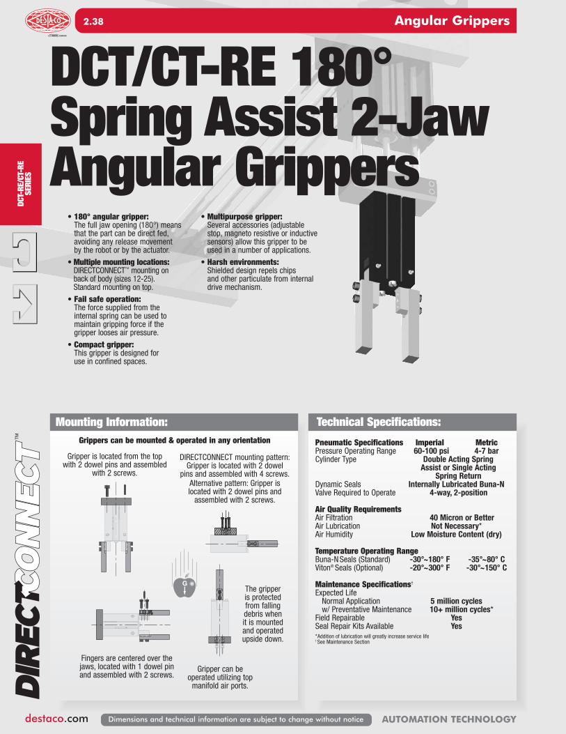
DCT-RE
/CT-RE
SERIES
Angular Grippers
destaco.com
2.38
AUTOMATION TECHNOLOGYDimensions and technical information are subject to change without notice
Pneumatic Specifications Imperial MetricPressure Operating Range 60-100 psi 4-7 barCylinder Type Double Acting Spring
Assist or Single ActingSpring Return
Dynamic Seals Internally Lubricated Buna-NValve Required to Operate 4-way, 2-position
Air Quality RequirementsAir Filtration 40 Micron or BetterAir Lubrication Not Necessary*Air Humidity Low Moisture Content (dry)
Temperature Operating RangeBuna-NSeals (Standard) -30°~180° F -35°~80° CViton® Seals (Optional) -20°~300° F -30°~150° C
Maintenance Specifications†
Expected Life Normal Application 5 million cyclesw/ Preventative Maintenance 10+ million cycles*
Field Repairable YesSeal Repair Kits Available Yes*Addition of lubrication will greatly increase service life† See Maintenance Section
Technical Specifications:Grippers can be mounted & operated in any orientation
Mounting Information:
DCT/CT-RE 180°Spring Assist 2-JawAngular Grippers
• 180° angular gripper:The full jaw opening (180°) meansthat the part can be direct fed,avoiding any release movement by the robot or by the actuator.
• Multiple mounting locations:DIRECTCONNECT™ mounting on back of body (sizes 12-25). Standard mounting on top.
• Fail safe operation:The force supplied from the internal spring can be used to maintain gripping force if the gripper looses air pressure.
• Compact gripper:This gripper is designed for use in confined spaces.
• Multipurpose gripper:Several accessories (adjustable stop, magneto resistive or inductivesensors) allow this gripper to beused in a number of applications.
• Harsh environments:Shielded design repels chips and other particulate from internaldrive mechanism.
G
Gripper is located from the topwith 2 dowel pins and assembled
with 2 screws.
Fingers are centered over thejaws, located with 1 dowel pinand assembled with 2 screws.
The gripper is protectedfrom fallingdebris whenit is mountedand operatedupside down.
Gripper can be operated utilizing topmanifold air ports.
DIRECTCONNECT mounting pattern:Gripper is located with 2 dowel
pins and assembled with 4 screws. Alternative pattern: Gripper is located with 2 dowel pins andassembled with 2 screws.
2.1-2.44�(Angular)_�2.1-2.32�(Angular).qx4��7/23/14��9:36�AM��Page�38

DCT-RE/CT-RE
SERIES
Angular Grippers
destaco.com
2. 39
AUTOMATION TECHNOLOGY Dimensions and technical information are subject to change without notice
Product Features
Operating Principle
SeePage 2.40
Style -DCT-RE Angular GripperSize -12M Style: DCT-12M-RE
Stroke: 90° each fingerGrip Force: 9 lbs 40 NWeight: 0.26 lbs 0.12 Kg
• A double acting piston, with a ring magnet for magneto resistive sensing, isconnected to a fork driver on which 2 drive pins are fixed.
• Jaw rotation is synchronized with the drive pin-jaw assembly.
• Sliding in these slots, drive pins convert vertical motion of the piston intorotating opposite synchronous motion of both jaws.
• Each jaw has a useful rotation stroke of 90°, between the 90° open positionand the 0° gripping position, plus a gripping over-stroke of approximately1.5° before reaching the fully gripped position. Jaws have to be designedfor a 0° gripping position (parallel jaws)
• The fail safe spring allow the gripper to retain the component should the airsupply fail or for the gripper to be used in single acting mode.
SeePage 2.41
Style -DCT-RE Angular GripperSize -16M Style: DCT-16M-RE
Stroke: 90° each fingerGrip Force: 19 lbs 87 NWeight: 0.44 lbs 0.20 Kg
SeePage 2.42
Style -DCT-RE Angular GripperSize -20M Style: DCT-20M-RE
Stroke: 90° each fingerGrip Force: 32 lbs 141 NWeight: 0.73 lbs 0.33 Kg
SeePage 2.43
Style -DCT-RE Angular GripperSize -25M Style: DCT-25M-RE
Stroke: 90° each fingerGrip Force: 45 lbs 199 NmWeight: 1.26 lbs 0.57 Kg
SeePage 2.44
Style -CT-RE Angular GripperSize -32M Style: CT-32M-RE
Stroke: 90° each fingerGrip Force: 79 lbs 353 NWeight: 1.83 lbs 0.83 Kg
SeePage 2.45
Style-CT-RE Angular GripperSize -40M Style: CT-40M-RE
Stroke: 90° each fingerGrip Force: 133 lbs 592 NWeight: 3.06 lbs 1.39 Kg
SeePage 2.46
Style-CT-RE Angular GripperSize -50M Style: CT-50M-RE
Stroke: 90° each fingerGrip Force: 201 in-lbs 893 NWeight: 4.87 lbs 2.21 Kg
Shielded Plate and Wiper
CoversGripper body is shieldedto repel chips and otherparticulate from internal
drive mechanism
Inductive SensorMounting Kit
Accessory (SD) in orderto control jaw position:comes with 2 holders for
tubular sensors and 2 adjustable flags(except size -12)
Adjustable StopAccessory (BR) in order toadjust the opening of jaws,
between 0° to 180°
Fail Safe SpringInternal spring allows the gripper to hold onto part with loss of air
pressure
Magneto ResistiveSensor Mounting Kit
The gripper comes with adjustableslots for the 2 magnetic sensors
(to control jaw position)
Body
Cap
Piston
Magnet
Drive Pin Slot
Driver
Jaw
Shielded Plate
Pivot Pin
Wiper Cover
Fail Safe Spring
Drive Pin
Pressure
Exhaust
Exhaust
Pressure
MultipleAir PortsSide or top airports (top portsrequire O-ring)
Gripper AttachmentGripper mounting from
side or bottom
Viton SealsViton seals for high temperatures (-20°F to +300°F / -30°~150° C)
are optional
QualityComponents
Made from aluminum alloy anodized with
Teflon™ impregnation.The gripper's main
components are made of heat treated steel.
Mounting PatternsDIRECTCONNECT™
mounting surface on back of body (sizes 12-25)
2.1-2.44�(Angular)_�2.1-2.32�(Angular).qx4��7/14/14��10:42�PM��Page�39

DCT-RE SERIES
Angular Grippers
destaco.com
2.40
AUTOMATION TECHNOLOGYDimensions and technical information are subject to change without notice
DCT-12M-RE Product Specifications
90°90°
1.43736.5
0.359
2 Slots tomountmagnetic sensors
2.02851.5
CL
CL
1.1830
[MOPEN
3 x 5.5 DP]
0.964624.50
CLOSE(supplied plugged)
x 5.5 DP]Top air port
(supplied plugged)
Top air port
90.35
200.79
8.60.339
x 7 DP]32 x [M
0.570914.50
[M3
2 x [ 2.5H9 x 4.5 DP]
CL
CL
x 6 DP]OPEN
Side air port
0.0002
1.6
2.8346
0.650
5[M9
2 x [M
-0.0005-0.2362
] THRU3
0.39
72.00
16.5
0.318
0.35
Side air port
CLOSEx 6 DP]5[M
10
0.063
2.5264
[6g6]
[ 2.5E7] THRU
CL
Shielded plate
Jaws ingrippingpositionat 0°
CL
14.500.57093 x 7 DP]
25
0.964624.50
0.23618
2 x [M
803.15
6.0
0.98
35.001.3780
0.71
0.492112.50
2 x [ 2.5H7 x 4.5 DP]
4 x [M3
2 x [
9.50.375
3H7 x 6 DP]
19.050.7500
x 7 DP]
0.030.8
0.123
0.25 O-Ring [ 1 x 3]
Gripper'stop air port
Our grippers are supplied with open side air ports and top air ports plugged. When operating top air ports, produce manifold
sealing as shown.
Third Angle Projection
Dimensions are symmetrical about
centerline
Imperial in. Metric [mm]0.00 = ±.01 [0.] = [±.25]
0.000 = ±.005 [0.0] = [±.13]0.0000 = ±.0005 [0.00] = [±.013]
All Dowel Holes are SF (Slip Fit). Locational Tolerance
±.0005" or [±.013mm]
UNLESS OTHERWISE NOTED ALL TOLERANCES ARE AS SHOWN BELOW
Metric ThreadsCourse Pitch
How to Order: (Order Accessories separately from Basic Model)Loading Information
5
4
3
2
1
0
20
16
12
8
4
0
lbs. N
EFFECTIVE FINGER LENGTH FROM ROTATION AXIS - L
FING
ER F
ORCE
- F
/2
GRIP FORCE PER FINGER @ 0°
1 25
1.5 35
3 in. 76mm
WARNING! DO NOT EXCEED
MAXIMUM EFFECTIVE FINGER LENGTHS
2.0 50
2.5 64
100 PSI [7 bar]80 PSI [5.5 bar] 60 PSI [4.1 bar] 40 PSI [2.7 bar] 20 PSI [1.3 bar]
0 PSI [0 bar]
Loading Capacity†Static Dynamic
Imperial Metric Imperial Metric
Maximum Tensile T 11 lbs. 47 N 2 lbs. 9.4 NMaximum Compressive C 11 lbs. 47 N 2 lbs. 9.4 NMaximum Moment Mx 10 in.-lbs. 1.1 Nm 3 in.-lbs. 1.1 NmMaximum Moment My 10 in.-lbs. 1.1 Nm 3 in.-lbs. 1.1 NmMaximum Moment Mz 10 in.-lbs. 1.1 Nm 3 in.-lbs. 1.1 Nm
†Capacities are per set of jaws and are not simultaneous
Specifications DCT-12M-RETotal Rated Grip Force, F @ 100 psi [7 bar] L = 1 in. [25mm] @ 0°........................... 9 lbs. 40 N
Stroke........................................................ 90° of stroke for each fingerWeight ....................................................... 0.26 lbs. 0.12 KgPressure Range......................................... 60-100 psi 4-7 BarCylinder Bore Ø ......................................... 0.472 in. 12 mmDisplacement ............................................ 0.117 in3. 1.92 cm3
Temperature RangeStandard Seals....................................... -30°~180° F -35°~80° CViton® Seals ............................................ -20°~300° F -30°~150° C
Actuation (open/close)............................... 0.08 / 0.05 sec.Accuracy.................................................... ±0.0028 in. ±0.07 mmRepeatability.............................................. ±0.002 in. ±0.05 mmValve required to actuate single acting ..... 3-way, 2-positionValve required to actuate double acting.... 4-way, 2-position
0.59 [15]MAX.
0.20 [5]
ADJUSTABLE STOP KIT (BR)
0.31 [8]
M4
DCT - 12M - RE - VSIZE SPRING
BASIC MODEL VITON® SEALS
NOTE: Jaws have to be designed for a 0° gripping position (parallel jaws).Jaws will close 1.5° past parallel. To limit shocks at the end of an opening or closing stroke, it is highly recommended to design jaws with minimal inertia (as light and short as possible).Flow Controls make it possible to reduce the rotation speed and are highly recommended.
SENSOR ACCESSORIES*
PNP Magneto Resistive Sensor Short Barrel w/Qk Disc* OHSP-017 1 or 2NPN Magneto Resistive Sensor Short Barrel w/Qk Disc* OHSN-017 1 or 2Quick Disconnect 2 Meter Cable Length* CABL-010 1 or 2Quick Disconnect 5 Meter Cable Length* CABL-013 1 or 2
PNEUMATIC ACCESSORIESAdj. Flow Control M5 Elbow - 6mm OD Push-in (Metric) VLVF-008 1 or 2Buna-NSeal Repair Kit SLKT-159 1Viton® Seal Repair Kit SLKT-159V 1
MOUNTING ACCESSORIESAdjustment Stop Kit (1 Shielded Plate + 1 Stop) KP-DCT12-BR 1*Sensor and cable sold separately.
NOTE: DIRECTCONNECT™ DIMENSIONS ARE SHOWN IN BLUE
NOTE: DCT-12-RE can be used asan exact replacement for CT-12-RE
L XF/2F/2
ZMz
My
Z
YC T
Mx
2.1-2.44�(Angular)_�2.1-2.32�(Angular).qx4��7/14/14��10:42�PM��Page�40

DCT-RE SERIES
Angular Grippers
destaco.com
2. 41
AUTOMATION TECHNOLOGY Dimensions and technical information are subject to change without notice
DCT-16M-RE Product Specifications
How to Order: (Order Accessories separately from Basic Model)Loading Information
Loading Capacity†Static Dynamic
Imperial Metric Imperial Metric
Maximum Tensile T 20 lbs. 90 N 4 lbs. 18 NMaximum Compressive C 20 lbs. 90 N 4 lbs. 18 NMaximum Moment Mx 26 in.-lbs. 2.9 Nm 6 in.-lbs. 0.7 NmMaximum Moment My 26 in.-lbs. 2.9 Nm 6 in.-lbs. 0.7 NmMaximum Moment Mz 26 in.-lbs. 2.9 Nm 6 in.-lbs. 0.7 Nm
†Capacities are per set of jaws and are not simultaneous
0.45311.5
17
1.594
0.67
90°
40.5
90°
0.359
CL
CL
x 5.5 DP]OPEN
CLOSE(supplied plugged)
x 5.5 DP]Top air port
[M3
[M3
1.4236
1.141729.00
90.35
x 9 DP]42 x [M
100.39
250.98
Top air port
(supplied plugged)
0.708718.00
2 x [ 3H9 x 5.5 DP]
CL CL
CL
x 6 DP][M
0.3150 -
Side air port5
0.31
20.5
0.0002
2
0.807
E7] THRU[ 2.5
10
79.00
10
] THRU32 x [M
-0.0006
0.39
0.39
3.1102
8
Side air port
CLOSEx 6 DP]5[M
OPEN
0.08
2.8071
[8g6]
2 Slots tomountmagnetic sensors
56.52.224
1.51638.5
4 x [M3 x 5.5 DP]
CL
Shielded plate
Jaws ingrippingpositionat 0°
CL
2 x [M4 x 9 DP]
18.000.7087
3.4387
8.00.315
200.79
29.001.1417
1.04326.5
35.001.3780
0.551214.00
2 x [ 3H9 x 5.5 DP]
4 x [M x 7 DP]
H7 x 6 DP]
0.750019.05
32 x [
0.3759.5
3
0.030.8
0.123
0.25 O-Ring [ 1 x 3]
Gripper'stop air port
Our grippers are supplied with open side air ports and top air ports plugged. When operating top air ports, produce manifold
sealing as shown.
Third Angle Projection
Dimensions are symmetrical about
centerline
Imperial in. Metric [mm]0.00 = ±.01 [0.] = [±.25]
0.000 = ±.005 [0.0] = [±.13]0.0000 = ±.0005 [0.00] = [±.013]
All Dowel Holes are SF (Slip Fit). Locational Tolerance
±.0005" or [±.013mm]
UNLESS OTHERWISE NOTED ALL TOLERANCES ARE AS SHOWN BELOW
Metric ThreadsCourse Pitch
11
9
7
4
2
0
50
40
30
20
10
0
lbs. N
EFFECTIVE FINGER LENGTH FROM ROTATION AXIS - L
FING
ER F
ORCE
- F
/2
GRIP FORCE PER FINGER @ 0°
1 25
1.5 35
3 in. 76mm
WARNING! DO NOT EXCEED
MAXIMUM EFFECTIVE FINGER LENGTHS
2.0 50
2.5 64
100 PSI [7 bar]80 PSI [5.5 bar] 60 PSI [4.1 bar] 40 PSI [2.7 bar] 20 PSI [1.3 bar]
0 PSI [0 bar]
Specifications DCT-16M-RETotal Rated Grip Force, F @ 100 psi [7 bar] L = 1 in. [25mm] @ 0°........................... 19 lbs. 87 N
Stroke........................................................ 90° of stroke for each fingerWeight ....................................................... 0.44 lbs. 0.20 KgPressure Range......................................... 60-100 psi 4-7 BarCylinder Bore Ø ......................................... 0.630 in. 16 mmDisplacement ............................................ 0.251 in3. 4.12 cm3
Temperature RangeStandard Seals....................................... -30°~180° F -35°~80° CViton® Seals ............................................ -20°~300° F -30°~150° C
Actuation (open/close)............................... 0.15 / 0.12 sec.Accuracy.................................................... ±0.0028 in. ±0.07 mmRepeatability.............................................. ±0.002 in. ±0.05 mm.Valve required to actuate single acting ..... 3-way, 2-positionValve required to actuate double acting.... 4-way, 2-position
0.79 [20]MAX.
0.24 [6]
0.31 [8]
0.46 [11.7]
0.59 [15]
0.22 [5.5]0.48 [12.3]
1.40 [35.5]
INDUCTIVE SENSORS ANDMOUNTING KIT (SD)
ADJUSTABLE STOP KIT (BR)
0.16 [4]
2.38 [60.5]
0.24 [6] Sensors Ø 0.16 [4]
0.39 [10]
M5
DCT - 16M - RE - VSIZE SPRING
BASIC MODEL VITON® SEALS
NOTE: Jaws have to be designed for a 0° gripping position (parallel jaws).Jaws will close 1.5° past parallel. To limit shocks at the end of an opening or closing stroke, it is highly recommended to design jaws with minimal inertia (as light and short as possible).Flow Controls make it possible to reduce the rotation speed and are highly recommended.
SENSOR ACCESSORIES*PNP Magneto Resistive Sensor Short Barrel w/Qk Disc* OHSP-017 1 or 2NPN Magneto Resistive Sensor Short Barrel w/Qk Disc* OHSN-017 1 or 2Inductive Sensor Mounting Kit (mounts 2 sensors) SDCT16-20 14mm PNP Inductive Sensor with Quick Disconnect* OISP-014 1 or 24mm NPN Inductive Sensor with Quick Disconnect* OISN-014 1 or 2Quick Disconnect 2 Meter Cable Length* CABL-010 1 or 2Quick Disconnect 5 Meter Cable Length* CABL-013 1 or 2PNEUMATIC ACCESSORIESAdj. Flow Control M5 Elbow - 6mm OD Push-in (Metric) VLVF-008 1 or 2Buna-NSeal Repair Kit SLKT-160 1Viton® Seal Repair Kit SLKT-160V 1MOUNTING ACCESSORIESAdjustment Stop Kit (1 Shielded Plate + 1 Stop) KP-DCT16-BR 1*Sensor and cable sold separately.
NOTE: DIRECTCONNECT™ DIMENSIONS ARE SHOWN IN BLUE
NOTE: DCT-16-RE can be used asan exact replacement for CT-16-RE
L XF/2F/2
ZMz
My
Z
YC T
Mx
2.1-2.44�(Angular)_�2.1-2.32�(Angular).qx4��7/14/14��10:42�PM��Page�41

DCT-RE SERIES
Angular Grippers
destaco.com
2.42
AUTOMATION TECHNOLOGYDimensions and technical information are subject to change without notice
DCT-20M-RE Product Specifications
0.53113.5
220.87
49.5
47
90°
1.85
1.949
90°
CL
CL
OPEN(supplied plugged)
CLOSE(supplied plugged)
x 5.5 DP]Top air port
[M3 x 5.5 DP]
[M3
421.65
1.318933.50
10
x 11 DP]52 x [M
110.43
301.18
Top air port
0.39
0.846521.50
2 x [ 4H9 x 8 DP]
CL
Shielded plate
Jaws ingrippingpositionat 0°
CL
39.00
2 x [ 4H9 x 8 DP]
21.500.8465
4.09104
10.00.394
220.87
33.501.3189
1.3033
2 x [M5 x 11 DP]
1.5354
0.7874020.00
CL CL
CL
x 6 DP][M
0.3937 -
[
Side air port5
3.7008
[M5 x 6 DP]CLOSE
Side air port
25
0.318
12
94.00
0.96
2.6
3
0.0002
] THRU42 x [M
-0.0006
E7] THRU
0.43
0.47
11
OPEN
0.102
3.2783
[10g6]
2 Slots tomountmagnetic sensors
66.52.618
0.359
4 x [M3 x 5.5 DP]19.050.7500
x 6 DP]
H7 x 6 DP]2 x [
0.3759.5
3
34 x [M
0.030.8
0.123
0.25 O-Ring [ 1 x 3]
Gripper'stop air port
Our grippers are supplied with open side air ports and top air ports plugged. When operating top air ports, produce manifold
sealing as shown.
Third Angle Projection
Dimensions are symmetrical about
centerline
Imperial in. Metric [mm]0.00 = ±.01 [0.] = [±.25]
0.000 = ±.005 [0.0] = [±.13]0.0000 = ±.0005 [0.00] = [±.013]
All Dowel Holes are SF (Slip Fit). Locational Tolerance
±.0005" or [±.013mm]
UNLESS OTHERWISE NOTED ALL TOLERANCES ARE AS SHOWN BELOW
Metric ThreadsCourse Pitch
How to Order: (Order Accessories separately from Basic Model)Loading Information
16
13
11
9
7
4
2
0
70
60
50
40
30
20
10
0
lbs. N
EFFECTIVE FINGER LENGTH FROM ROTATION AXIS - L
FING
ER F
ORCE
- F
/2
GRIP FORCE PER FINGER @ 0°
1.25 32
1.75 44
2.25 57
2.75 70
3.25 in. 83mm
WARNING! DO NOT EXCEED
MAXIMUM EFFECTIVE FINGER LENGTHS
100 PSI [7 bar]80 PSI [5.5 bar] 60 PSI [4.1 bar] 40 PSI [2.7 bar] 20 PSI [1.3 bar] 0 PSI [0 bar]
Loading Capacity†Static Dynamic
Imperial Metric Imperial Metric
Maximum Tensile T 34 lbs. 150 N 7 lbs. 30 NMaximum Compressive C 34 lbs. 150 N 7 lbs. 30 NMaximum Moment Mx 53 in.-lbs. 6 Nm 13 in.-lbs. 1.5 NmMaximum Moment My 53 in.-lbs. 6 Nm 13 in.-lbs. 1.5 NmMaximum Moment Mz 53 in.-lbs. 6 Nm 13 in.-lbs. 1.5 Nm
†Capacities are per set of jaws and are not simultaneous
Specifications DCT-20M-RETotal Rated Grip Force, F @ 100 psi [7 bar] L = 1.25 in. [32mm] @ 0°...................... 32 lbs. 141 N
Stroke........................................................ 90° of stroke for each fingerWeight ....................................................... 0.73 lbs. 0.33 KgPressure Range......................................... 60-100 psi 4-7 BarCylinder Bore Ø ......................................... 0.787 in. 20 mmDisplacement ............................................ 0.483 in3. 7.92 cm3
Temperature RangeStandard Seals....................................... -30°~180° F -35°~80° CViton® Seals ............................................ -20°~300° F -30°~150° C
Actuation (open/close)............................... 0.20 / 0.14 sec.Accuracy.................................................... ±0.003 in. ±0.08 mmRepeatability.............................................. ±0.002 in. ±0.05 mmValve required to actuate single acting ..... 3-way, 2-positionValve required to actuate double acting.... 4-way, 2-position
0.98 [25]MAX.
0.31 [8]
0.31 [8]
0.46 [11.7]
0.59 [15]
0.48 [8]0.48 [12.3]
1.73 [44]
INDUCTIVE SENSORS ANDMOUNTING KIT (SD)
ADJUSTABLE STOP KIT (BR)
0.14 [3.5]
2.79 [71]
0.24 [6] Sensors Ø 0.16 [4]
0.47 [12]
M6
NOTE: Jaws have to be designed for a 0° gripping position (parallel jaws).Jaws will close 1.5° past parallel. To limit shocks at the end of an opening or closing stroke, it is highly recommended to design jaws with minimal inertia (as light and short as possible).Flow Controls make it possible to reduce the rotation speed and are highly recommended.
SENSOR ACCESSORIES*PNP Magneto Resistive Sensor Short Barrel w/Qk Disc* OHSP-017 1 or 2NPN Magneto Resistive Sensor Short Barrel w/Qk Disc* OHSN-017 1 or 2Inductive Sensor Mounting Kit (mounts 2 sensors) SDCT16-20 14mm PNP Inductive Sensor with Quick Disconnect* OISP-014 1 or 24mm NPN Inductive Sensor with Quick Disconnect* OISN-014 1 or 2Quick Disconnect 2 Meter Cable Length* CABL-010 1 or 2Quick Disconnect 5 Meter Cable Length* CABL-013 1 or 2PNEUMATIC ACCESSORIESAdj. Flow Control M5 Elbow - 6mm OD Push-in (Metric) VLVF-008 1 or 2Buna-NSeal Repair Kit SLKT-161 1Viton® Seal Repair Kit SLKT-161V 1MOUNTING ACCESSORIESAdjustment Stop Kit (1 Shielded Plate + 1 Stop) KP-DCT20-BR 1*Sensor and cable sold separately.
NOTE: DIRECTCONNECT™ DIMENSIONS ARE SHOWN IN BLUE
NOTE: DCT-20-RE can be used asan exact replacement for CT-20-RE
DCT - 20M - RE - VSIZE SPRING
BASIC MODEL VITON® SEALS
L XF/2F/2
ZMz
My
Z
YC T
Mx
2.1-2.44�(Angular)_�2.1-2.32�(Angular).qx4��7/14/14��10:42�PM��Page�42

DCT-RE SERIES
Angular Grippers
destaco.com
2. 43
AUTOMATION TECHNOLOGY Dimensions and technical information are subject to change without notice
DCT-25M-RE Product Specifications
5.00127
0.4712
1.0226
2.007951.00
Shielded plate
Jaws ingrippingposition
at 0°
CL
0.4712
2 x [M6 x 13 DP]
0.4311
1.4236
0.6918
[M5 x 6 DP]OPEN
(supplied plugged)
[M5 x 6 DP]CLOSE
(supplied plugged)
1.574840.00
1.023626.00
2 x 0.1969 SFx 0.39 [10] DP
[ 5H9]
0.68917.5
CL
CL
4.5079114.50
0.5915
0.4724 -0.0007-0.0002
2 x [M5]
0.1575 SF
1.12228.5
0.3910
0.4311[M5 x 6 DP]
CLOSE[M5 x 6 DP]
OPEN
0.1303.3
4.02102
[ 4E7]
[12g6]
CLCL
CL
3.2382
0.2957.5
2.38260.5
1.04326.5
4 x [M3 x 7 DP]
0.9825.00
1.0226.00
1.5740.00
90°90°
2.3259
2 Slots to mount magnetic sensors
0.030.8
0.123
0.25 O-Ring [ 1 x 3]
Gripper'stop air port
Our grippers are supplied with open side air ports and top air ports plugged. When operating top air ports, produce manifold
sealing as shown.
1.5000(Dowels)
38.10
0.75019.1
4 x [M5 x 11 DP]
2 x [ 5H7 x 10 DP]
2x[ 5 H9 x10DP]
CL
Third Angle Projection
Dimensions are symmetrical about
centerline
Imperial in. Metric [mm]0.00 = ±.01 [0.] = [±.25]
0.000 = ±.005 [0.0] = [±.13]0.0000 = ±.0005 [0.00] = [±.013]
All Dowel Holes are SF (Slip Fit). Locational Tolerance
±.0005" or [±.013mm]
UNLESS OTHERWISE NOTED ALL TOLERANCES ARE AS SHOWN BELOW
Metric ThreadsCourse Pitch
Specifications DCT-25M-RETotal Rated Grip Force, F @ 100 psi [7 bar] L = 1.75 in. [44mm] @ 0°...................... 45 lbs. 199 N
Stroke........................................................ 90° of stroke for each fingerWeight ....................................................... 1.26 lbs. 0.57 KgPressure Range......................................... 60-100 psi 4-7 BarCylinder Bore Ø ......................................... 0.984 in. 25 mmDisplacement ............................................ 0.909 in3. 14.9 cm3
Temperature RangeStandard Seals....................................... -30°~180° F -35°~80° CViton® Seals ............................................ -20°~300° F -30°~150° C
Actuation (open/close)............................... 0.25 / 0.19 sec.Accuracy.................................................... ±0.003 in. ±0.08 mmRepeatability.............................................. ±0.002 in. ±0.05 mm.Valve required to actuate single acting ..... 3-way, 2-positionValve required to actuate double acting.... 4-way, 2-position
How to Order: (Order Accessories separately from Basic Model)Loading Information
22
18
13
9
4
0
100
80
60
40
20
0
lbs. N
EFFECTIVE FINGER LENGTH FROM ROTATION AXIS - L
FING
ER F
ORCE
- F
/2
GRIP FORCE PER FINGER @ 0°
1.75 44
2.25 57
2.75 70
3.25 81
3.75 95
4.25 108
4.75 in. 121mm
WARNING! DO NOT EXCEED
MAXIMUM EFFECTIVE FINGER LENGTHS
100 PSI [7 bar]80 PSI [5.5 bar] 60 PSI [4.1 bar]
20 PSI [1.3 bar]
40 PSI [2.7 bar]
0 PSI [0 bar]
Loading Capacity†Static Dynamic
Imperial Metric Imperial Metric
Maximum Tensile T 46 lbs. 205 N 9 lbs. 41 NMaximum Compressive C 46 lbs. 205 N 9 lbs. 41 NMaximum Moment Mx 89 in.-lbs. 10 Nm 22 in.-lbs. 2.5 NmMaximum Moment My 89 in.-lbs. 10 Nm 22 in.-lbs. 2.5 NmMaximum Moment Mz 89 in.-lbs. 10 Nm 22 in.-lbs. 2.5 Nm
†Capacities are per set of jaws and are not simultaneous
1.18 [30]MAX.
0.39 [10]
0.43 [11]
0.63 [16]
0.63 [16]
0.37 [9.5]0.79 [20]
2.21 [56.2]
INDUCTIVE SENSORS ANDMOUNTING KIT (SD)
ADJUSTABLE STOP KIT (BR)
0.18 [4.5]
3.44 [87.5]
0.39 [10] Sensors Ø 0.31 [8]
0.55 [14]
M6
NOTE: Jaws have to be designed for a 0° gripping position (parallel jaws).Jaws will close 1.5° past parallel. To limit shocks at the end of an opening or closing stroke, it is highly recommended to design jaws with minimal inertia (as light and short as possible).Flow Controls make it possible to reduce the rotation speed and are highly recommended.
SENSOR ACCESSORIES*PNP Magneto Resistive Sensor Short Barrel w/Qk Disc* OHSP-017 1 or 2NPN Magneto Resistive Sensor Short Barrel w/Qk Disc* OHSN-017 1 or 2Inductive Sensor Mounting Kit (mounts 2 sensors) SDCT25-32 1M8 PNP Inductive Sensor with Quick Disconnect* OISP-011 1 or 2M8 NPN Inductive Sensor with Quick Disconnect* OISN-011 1 or 2Quick Disconnect 2 Meter Cable Length* CABL-010 1 or 2Quick Disconnect 5 Meter Cable Length* CABL-013 1 or 2PNEUMATIC ACCESSORIESM5 Adjustable Flow Control VLVF-008 1 or 2Buna-NSeal Repair Kit SLKT-162 1Viton® Seal Repair Kit SLKT-162V 1MOUNTING ACCESSORIESAdjustment Stop Kit (1 Shielded Plate + 1 Stop) KP-DCT25-BR 1*Sensor and cable sold separately.
NOTE: DIRECTCONNECT™ DIMENSIONS ARE SHOWN IN BLUE
DCT - 25M - RE - VSIZE SPRING
BASIC MODEL VITON® SEALS
L XF/2F/2
ZMz
My
Z
YC T
Mx
2.1-2.44�(Angular)_�2.1-2.32�(Angular).qx4��7/14/14��10:42�PM��Page�43

CT-RE SERIES
Angular Grippers
destaco.com
2.44
AUTOMATION TECHNOLOGYDimensions and technical information are subject to change without notice
CT-32M-RE Product Specifications
1.1417 ±0.000629 ±0.016
5.71145
2 x 0.2362 0.0000+0.0012
x 0.47 [12] DP
6 0+0.03
0.55114
1.1028
2 x M8 x 0.67 [17] DP
1.1811 ±0.001030 ±0.026
1.6929 ±0.000743 ±0.019
1.7745
Shielded plate Jaws ingrippingposition
at 0°
CL
0.7519
2 x M8x 0.67 [17] DP
0.4712
1.6542
2.2056
M5 x 0.24 [6] DPOPEN
(supplied plugged)
Top air port
M5 x 0.24 [6] DPCLOSE
(supplied plugged)
Top air port
1.6929 ±0.000743 ±0.019
1.1417 ±0.000629 ±0.016
2 x 0.2362 0.0000+0.0012
x 0.47 [12] DP
6 0+0.03
0.8521.5
CL
CL
5.1575 ±0.0049131 ±0.125
= 0.67 =17
0.5512 -0.0007-0.0002
14 -0.017-0.006
2 x M6
0.1969 +0.0008+0.00135 +0.020
+0.032
1.3033
0.4712
0.4712
M5 x 0.24 [6] DPCLOSE
Side air portM5 x 0.24 [6] DPOPEN
Side air port
0.153.9
4.57116
CL
CL
3.7094
0.307.50
2.8572.50
1.2431.50
4 x [M3 x 7]
90°
2.6467
90°
2 Slots to mount magnetic sensors
0.051.2
0.144
0.318 O-Ring [Ø1.5 x Ø5 ]
Gripper'stop air port
Our grippers are supplied with open side air ports and top air ports plugged. When operating top air ports, produce manifold
sealing as shown.
Third Angle Projection
Dimensions are symmetrical about
centerline
Imperial in. Metric [mm]0.00 = ±.01 [0.] = [±.25]
0.000 = ±.005 [0.0] = [±.13]0.0000 = ±.0005 [0.00] = [±.013]
All Dowel Holes are SF (Slip Fit). Locational Tolerance
±.0005" or [±.013mm]
UNLESS OTHERWISE NOTED ALL TOLERANCES ARE AS SHOWN BELOW
Metric ThreadsCourse Pitch
How to Order: (Order Accessories separately from Basic Model)Loading Information
40
34
27
20
13
7
0
180
150
120
90
60
30
0
lbs. N
EFFECTIVE FINGER LENGTH FROM ROTATION AXIS - L
FING
ER F
ORCE
- F
/2
GRIP FORCE PER FINGER @ 0°
1.75 44
2.25 57
2.75 70
3.25 81
4.25 108
3.75 95
4.75 120
5.25 133
5.75 in. 146mm
WARNING! DO NOT EXCEED
MAXIMUM EFFECTIVE FINGER LENGTHS
100 PSI [7 bar]80 PSI [5.5 bar] 60 PSI [4.1 bar] 40 PSI [2.7 bar] 20 PSI [1.3 bar]
0 PSI [0 bar]
Loading Capacity†Static Dynamic
Imperial Metric Imperial Metric
Maximum Tensile T 65 lbs. 288 N 13 lbs. 57.6 NMaximum Compressive C 65 lbs. 288 N 13 lbs. 57.6 NMaximum Moment Mx 142 in.-lbs. 16 Nm 35 in.-lbs. 4 NmMaximum Moment My 142 in.-lbs. 16 Nm 35 in.-lbs. 4 NmMaximum Moment Mz 142 in.-lbs. 16 Nm 35 in.-lbs. 4 Nm
†Capacities are per set of jaws and are not simultaneous
Specifications CT-32M-RETotal Rated Grip Force, F @ 100 psi [7 bar]
L = 1.75 in. [44mm] @ 0° ................ 79 lbs. 353 NStroke........................................................ 90° of stroke for each fingerWeight ....................................................... 1.83 lbs. 0.83 KgPressure Range......................................... 60-100 psi 4-7 BarCylinder Bore Ø ......................................... 1.260 in. 32 mmDisplacement ............................................ 1.745 in3. 28.6 cm3
Temperature RangeStandard Seals....................................... -30°~180° F -35°~80° CViton® Seals ............................................ -20°~300° F -30°~150° C
Actuation (open/close)............................... 0.35 / 0.26 sec.Accuracy.................................................... ±0.003 in. ±0.08 mmRepeatability.............................................. ±0.002 in. ±0.05 mmValve required to actuate single acting ..... 3-way, 2-positionValve required to actuate double acting.... 4-way, 2-position
1.40 [35]MAX.
0.47 [12]
0.43 [11]
0.63 [16]
0.63 [16]
0.47 [12]0.79 [20]
2.68 [68.2]
INDUCTIVE SENSORS ANDMOUNTING KIT (SD)
ADJUSTABLE STOP KIT (BR)
0.16 [4]
3.94 [100]
0.39 [10] Sensors Ø 0.31 [8]
0.63 [16]
M8
CT - 32M - RE - VSIZE SPRING
BASIC MODEL VITON® SEALS
NOTE: Jaws have to be designed for a 0° gripping position (parallel jaws).Jaws will close 1.5° past parallel. To limit shocks at the end of an opening or closing stroke, it is highly recommended to design jaws with minimal inertia (as light and short as possible).Flow Controls make it possible to reduce the rotation speed and are highly recommended.
SENSOR ACCESSORIES*PNP Magneto Resistive Sensor Short Barrel w/Qk Disc* OHSP-017 1 or 2NPN Magneto Resistive Sensor Short Barrel w/Qk Disc* OHSN-017 1 or 2Inductive Sensor Mounting Kit (mounts 2 sensors) SDCT25-32 1M8 PNP Inductive Sensor with Quick Disconnect* OISP-011 1 or 2M8 NPN Inductive Sensor with Quick Disconnect* OISN-011 1 or 2Quick Disconnect 2 Meter Cable Length* CABL-010 1 or 2Quick Disconnect 5 Meter Cable Length* CABL-013 1 or 2PNEUMATIC ACCESSORIESAdj. Flow Control M5 Elbow - 6mm OD Push-in (Metric) VLVF-008 1 or 2Buna-NSeal Repair Kit SLKT-163 1Viton® Seal Repair Kit SLKT-163V 1MOUNTING ACCESSORIESAdjustment Stop Kit (1 Shielded Plate + 1 Stop) KP-CT32-BR 1*Sensor and cable sold separately.
L XF/2F/2
ZMz
My
Z
YC T
Mx
2.1-2.44�(Angular)_�2.1-2.32�(Angular).qx4��7/14/14��10:42�PM��Page�44

CT-RE SERIES
Angular Grippers
destaco.com
2. 45
AUTOMATION TECHNOLOGY Dimensions and technical information are subject to change without notice
CT-40M-RE Product Specifications
Third Angle Projection
Dimensions are symmetrical about
centerline
Imperial in. Metric [mm]0.00 = ±.01 [0.] = [±.25]
0.000 = ±.005 [0.0] = [±.13]0.0000 = ±.0005 [0.00] = [±.013]
All Dowel Holes are SF (Slip Fit). Locational Tolerance
±.0005" or [±.013mm]
UNLESS OTHERWISE NOTED ALL TOLERANCES ARE AS SHOWN BELOW
Metric ThreadsCourse Pitch
Specifications CT-40M-RETotal Rated Grip Force, F @ 100 psi [7 bar] L = 2 in. [51mm] @ 0°........................... 133 lbs. 592 N
Stroke........................................................ 90° of stroke for each fingerWeight ....................................................... 3.06 lbs. 1.39 KgPressure Range......................................... 60-100 psi 4-7 BarCylinder Bore Ø ......................................... 1.575 in. 40 mmDisplacement ............................................ 3.173 in3. 52 cm3
Temperature RangeStandard Seals....................................... -30°~180° F -35°~80° CViton® Seals ............................................ -20°~300° F -30°~150° C
Actuation (open/close)............................... 0.47 / 0.38 sec.Accuracy.................................................... ±0.0036 in. ±0.09 mmRepeatability.............................................. ±0.002 in. ±0.05 mm.Valve required to actuate single acting ..... 3-way, 2-positionValve required to actuate double acting.... 4-way, 2-position
90°
2.93374.5
90°
1.00425.5
512.01 x 8 DP]4
783.07
1094.29
0.7920
4 x [M
2 Slots to mount magnetic sensors
CLCL
CL
0.1543.9
5.31135
[ 5
0.00020.67
151.505.9646
-
2 x [M
E7]
-0.0007
]6
SF0.1969
39.51.555
120.47
180.71
[G 1/8 x 8 DP]
CLOSE[G 1/8 x 8 DP]
OPEN
170.6299
[16g6]
CL
32.00
1.5354
H9] 6
49
2 x
0.63
1.2598
Shielded plate
2 x [M
1.93
x 0.47 [12] DP SF
39.00
6.516
161.34
0.2362
x 17 DP]8
2.086653.00
34
165.5
[
Jaws ingrippingpositionat 0°
CL
CL
2.086653.00
1.535439.00
x 6 DP]
x 6 DP]
2 x
0.71
SF
x 17 DP]8
180.71
0.2362
OPEN
x 0.47 [12] DP
(supplied plugged)
518
522.05
662.60
5[M
(supplied plugged)CLOSE
2 x [M
[M
[ 6H9]
0.051.2
0.144
0.318 O-Ring [Ø1.5 x Ø5 ]
Gripper'stop air port
Our grippers are supplied with open side air ports and top air ports plugged. When operating top air ports, produce manifold
sealing as shown.
How to Order: (Order Accessories separately from Basic Model)Loading Information
67
56
45
34
22
11
0
300
250
200
150
100
50
0
lbs. N
EFFECTIVE FINGER LENGTH FROM ROTATION AXIS - L
FING
ER F
ORCE
- F
/2
GRIP FORCE PER FINGER @ 0°
2 51
3 76
4 102
5 127
6 152
7 in. 178mm
WARNING! DO NOT EXCEED
MAXIMUM EFFECTIVE FINGER LENGTHS
100 PSI [7 bar]80 PSI [5.5 bar] 60 PSI [4.1 bar] 20 PSI [1.3 bar]
40 PSI [2.7 bar]
0 PSI [0 bar]
1.57 [40]MAX.
0.47 [12]
0.69 [17.5]
0.83 [21]
1.18 [30]
0.57 [14.5]0.87 [22]
2.87 [73]
INDUCTIVE SENSORS ANDMOUNTING KIT (SD)
ADJUSTABLE STOP KIT (BR)
0.22 [5.5]
4.59 [116.5]
0.39 [10] Sensors Ø 0.47 [12]
0.63 [16]
M8
CT - 40M - RE - VSIZE SPRING
BASIC MODEL VITON® SEALS
NOTE: Jaws have to be designed for a 0° gripping position (parallel jaws).Jaws will close 1.5° past parallel. To limit shocks at the end of an opening or closing stroke, it is highly recommended to design jaws with minimal inertia (as light and short as possible).Flow Controls make it possible to reduce the rotation speed and are highly recommended.
SENSOR ACCESSORIES*PNP Magneto Resistive Sensor Short Barrel M8 w/Qk Disc* OHSP-017 1 or 2NPN Magneto Resistive Sensor Short Barrel M8 w/Qk Disc* OHSN-017 1 or 2Inductive Sensor Mounting Kit (mounts 2 sensors) SDCT40-63 1M12 PNP Inductive Sensor with M12 Quick Disconnect* OISP-017 1 or 2M12 NPN Inductive Sensor with M12 Quick Disconnect* OISN-017 1 or 2M8 Quick Disconnect 2 Meter Cable Length* CABL-010 1 or 2M8 Quick Disconnect 5 Meter Cable Length* CABL-013 1 or 2M12 Quick Disconnect 2 Meter Cable Length* CABL-014 1 or 2M12 Quick Disconnect 5 Meter Cable Length* CABL-018 1 or 2PNEUMATIC ACCESSORIESAdj. Flow Control G1/8 Elbow - 6mm OD Push-in (Metric) VLVF-005 1 or 2Buna-NSeal Repair Kit SLKT-164 1Viton® Seal Repair Kit SLKT-164V 1MOUNTING ACCESSORIESAdjustment Stop Kit (1 Shielded Plate + 1 Stop) KP-CT40-BR 1*Sensor and cable sold separately.
L XF/2F/2
ZMz
My
Z
YC T
Mx
Loading Capacity†Static Dynamic
Imperial Metric Imperial Metric
Maximum Tensile T 94 lbs. 420 N 19 lbs. 84 NMaximum Compressive C 94 lbs. 420 N 19 lbs. 84 NMaximum Moment Mx 195 in.-lbs. 22 Nm 49 in.-lbs. 5.5 NmMaximum Moment My 195 in.-lbs. 22 Nm 49 in.-lbs. 5.5 NmMaximum Moment Mz 195 in.-lbs. 22 Nm 49 in.-lbs. 5.5 Nm
†Capacities are per set of jaws and are not simultaneous
2.1-2.44�(Angular)_�2.1-2.32�(Angular).qx4��7/14/14��10:42�PM��Page�45

CT-RE SERIES
Angular Grippers
destaco.com
2.46
AUTOMATION TECHNOLOGYDimensions and technical information are subject to change without notice
CT-50-RE Product Specifications
1.1830
90°
3.5490
90°
CL
1.8110
0.71
8[2 x
2 x [M
1.574840.00
Shielded plate
H9]
2.3660
x 0.63 [16] DP SF
46.00
7.91
181.57
0.3150
x 22 DP]10
2.362260.00
40
201
Jaws ingrippingpositionat 0°
CL
CL
2.362260.00
30
2.44
x 6 DP]
62
2 x
1.18
SF
x 21 DP]10
250.98
0.3150
OPEN
x 0.63 [16] DP
(supplied plugged)
5 x 6 DP]
1.811046.00
762.99
5[M
(supplied plugged)CLOSE
2 x [M
[M
[ 8H9]
CLCL
CL
0.205
6.42163
[ 6
0.00020.83
183.007.2047
-
2 x [M
E7]
-0.0007
]8
SF0.2362
441.73
150.59
250.98
[G 1/8 x 8 DP]
CLOSE[G 1/8 x 8 DP]
OPEN
210.7087
[18g6]
4 x 8 DP]60
2.36
133
20
4.035
5.24102.50
0.79
4 x [M
2 Slots to mount magnetic sensors
0.051.2
0.144
0.318 O-Ring [Ø1.5 x Ø5 ]
Gripper'stop air port
Our grippers are supplied with open side air ports and top air ports plugged. When operating top air ports, produce manifold
sealing as shown.
Third Angle Projection
Dimensions are symmetrical about
centerline
Imperial in. Metric [mm]0.00 = ±.01 [0.] = [±.25]
0.000 = ±.005 [0.0] = [±.13]0.0000 = ±.0005 [0.00] = [±.013]
All Dowel Holes are SF (Slip Fit). Locational Tolerance
±.0005" or [±.013mm]
UNLESS OTHERWISE NOTED ALL TOLERANCES ARE AS SHOWN BELOW
Metric ThreadsCourse Pitch
How to Order: (Order Accessories separately from Basic Model)Loading Information
101
90
79
67
56
45
34
22
11
0
450
400
350
300
250
200
150
100
50
0
lbs. N
EFFECTIVE FINGER LENGTH FROM ROTATION AXIS - L
FING
ER F
ORCE
- F
/2
GRIP FORCE PER FINGER @ 0°
2.5 64
3.5 89
4.5 102
5.5 140
6.5 165
7.5 191
8.5 216
9.5 in. 241mm
WARNING! DO NOT EXCEED
MAXIMUM EFFECTIVE FINGER LENGTHS
100 PSI [7 bar]
80 PSI [5.5 bar]
60 PSI [4.1 bar] 40 PSI [2.7 bar] 20 PSI [1.3 bar] 0 PSI [0 bar]
Loading Capacity†Static Dynamic
Imperial Metric Imperial Metric
Maximum Tensile T 110 lbs. 490 N 22 lbs. 98 NMaximum Compressive C 110 lbs. 490 N 22 lbs. 98 NMaximum Moment Mx 266 in.-lbs. 30 Nm 66 in.-lbs. 7.5 NmMaximum Moment My 266 in.-lbs. 30 Nm 66 in.-lbs. 7.5 NmMaximum Moment Mz 266 in.-lbs. 30 Nm 66 in.-lbs. 7.5 Nm
†Capacities are per set of jaws and are not simultaneous
Specifications CT-50M-RETotal Rated Grip Force, F @ 100 psi [7 bar] L = 2.5 in. [64mm] @ 0°........................ 201 lbs. 893 N
Stroke........................................................ 90° of stroke for each fingerWeight ....................................................... 4.87 lbs. 2.21 KgPressure Range......................................... 60-100 psi 4-7 BarCylinder Bore Ø ......................................... 1.968 in. 50 mmDisplacement ............................................ 5.614 in3. 92 cm3
Temperature RangeStandard Seals....................................... -30°~180° F -35°~80° CViton® Seals ............................................ -20°~300° F -30°~150° C
Actuation (open/close)............................... 0.54 / 0.42 sec.Accuracy.................................................... ±0.0036 in. ±0.09 mmRepeatability.............................................. ±0.002 in. ±0.05 mm.Valve required to actuate single acting ..... 3-way, 2-positionValve required to actuate double acting.... 4-way, 2-position
1.77 [45]MAX.
0.63 [16]
0.69 [17.5]
0.83 [21]
1.18 [30]
0.75 [19]0.87 [22]
3.84 [97.5]
INDUCTIVE SENSORS ANDMOUNTING KIT (SD)
ADJUSTABLE STOP KIT (BR)
0.20 [5]
5.55 [141]
0.39 [10] Sensors Ø 0.47 [12]
0.79 [20]
M10
NOTE: Jaws have to be designed for a 0° gripping position (parallel jaws).Jaws will close 1.5° past parallel. To limit shocks at the end of an opening or closing stroke, it is highly recommended to design jaws with minimal inertia (as light and short as possible).Flow Controls make it possible to reduce the rotation speed and are highly recommended.
SENSOR ACCESSORIES*PNP Magneto Resistive Sensor Short Barrel M8 w/Qk Disc* OHSP-017 1 or 2NPN Magneto Resistive Sensor Short Barrel M8 w/Qk Disc* OHSN-017 1 or 2Inductive Sensor Mounting Kit (mounts 2 sensors) SDCT40-63 1M12 PNP Inductive Sensor with Quick Disconnect* OISP-017 1 or 2M12 NPN Inductive Sensor with Quick Disconnect* OISN-017 1 or 2M8 Quick Disconnect 2 Meter Cable Length* CABL-010 1 or 2M8 Quick Disconnect 5 Meter Cable Length* CABL-013 1 or 2M12 Quick Disconnect 2 Meter Cable Length* CABL-014 1 or 2M12 Quick Disconnect 5 Meter Cable Length* CABL-018 1 or 2PNEUMATIC ACCESSORIESAdj. Flow Control G1/8 Elbow - 6mm OD Push-in (Metric) VLVF-005 1 or 2Buna-NSeal Repair Kit SLKT-165 1Viton® Seal Repair Kit SLKT-165V 1MOUNTING ACCESSORIESAdjustment Stop Kit (1 Shielded Plate + 1 Stop) KP-CT50-BR 1*Sensor and cable sold separately.
CT - 50M - RE - VSIZE SPRING
BASIC MODEL VITON® SEALS
L XF/2F/2
ZMz
My
Z
YC T
Mx
2.1-2.44�(Angular)_�2.1-2.32�(Angular).qx4��7/14/14��10:42�PM��Page�46

CT-RE SERIES
Angular Grippers
destaco.com
2. 47
AUTOMATION TECHNOLOGY Dimensions and technical information are subject to change without notice
Notes
2.1-2.44�(Angular)_�2.1-2.32�(Angular).qx4��7/14/14��10:42�PM��Page�47

FUA
SERI
ESAngular Grippers
destaco.com
2.48
AUTOMATION TECHNOLOGYDimensions and technical information are subject to change without notice
FUA Stainless Food Gripper 4-JawAngular GrippersFEATURES & BENEFITS:• Designed for direct product contact in the food zone, according to the food industry standard (EN 1672-2)
• All parts are corrosion resistant, non-toxic, non-contaminating, non-porous, non-absorbent and non-reactive
• Stainless steel design resists chemical cleaning procedures
• Optional body made of High Performance Polymer, conform to FDA, for a significantly lighter weight
• Electro-polished exterior with no recessed or inaccessible zones prevents retention of contaminants and simplifies cleaning
• Sealed motion components (IP69K design) for high-pressure and high-temperature daily cleanings
• Any metal/metal contact protected by gasket to obtain a leakproof assembly against bacteria
• Angular gripper design for easier radial sealing of jaws
• Optional security springs for external gripping, in case ofair supply failure, in single acting or spring assist mode
• No external fasteners to avoid any foreign matter in food
• Contains special lubricants suitable for food industry
• Long maintenance-free service life
APPLICATIONS:• Food zone and splash zone handling of product
• Non-food zone applications
• Other applications requiring a sealed and corrosion resistant gripper
Shown with Optional Finger Attachment Kit
2.1-2.44�(Angular)_�2.1-2.32�(Angular).qx4��7/23/14��9:36�AM��Page�48

20°
Ø 70 [2.76]
90
°
35
[1
.38
] js
8
17.5°
17 [0.67] js8
17.5°
10°
46
.5 [
1.8
3]
35
[1
.38
]
Gasket
Air PortOPEN
Ø 6 [0.24[H9] x 10 [0.39] DP
4 x M5 x 11 [0.43] DP
CLOSEAir Port
B
B
CLOSED GRIPPER
0° Mid-Stroke
SCALE 1 : 1SECTION B-B
Gasket (supplied)
O-Ring (supplied)
2 x Air ports
5
1.2 [0.05]
Ø 8 [0.31]
M
6.7 [0.26]
SECTION A-A SCALE 2 : 3
Gasket (supplied)
4 x Jaws
5 [0.20] H8
2.5 [0.10]
9.5 [0.37]
M4
0° Mid-Stroke
Gasket (supplied)
OPEN GRIPPER
Ø 28 [1.10]
A
A
62
[2
.44
]Ø50 [Ø1.97] h7
3 [
0.1
2]
60 [2.36]
100 [3.94]
Ø 90 [3.54]
12 [0.47]
FUA SERIES
Angular Grippers
destaco.com
2. 49
AUTOMATION TECHNOLOGY Dimensions and technical information are subject to change without notice
FUA-63M Product Specifications
How to Order: (Order Accessories separately from Basic Model)
MATERIAL LI Body made of High Performance Polymer__ Leave Blank. Stainless Steel (Standard)
SPRING C Closed__ Leave Blank. No Spring Option (Standard)
SAMPLE ORDER: FUA-63M-LI-CEx: FUA-63M Food Gripper, Polymer Body, Spring Closed
BASIC MODEL MATERIAL
SPRING
ACCESSORIES ORDER # QTY/UNIT
Fingers Attachment Kit (includes 8 x SS Screws & Gaskets) KVMFUA63 1FUA-63M - LI - C
Specifications FUA-63M
Torque, Jaws @ O° (mid-stroke)6 bar with springs ...................................................................... 32 Nm0 bar with springs ...................................................................... 9 Nm
Total Stroke .................................................................................... 70° Weight.............................................................................................
Stainless Steel ............................................................................ 1.7 KgPloymer ...................................................................................... 0.8 Kg
Pressure Range (without springs).................................................. 2-7 barPressure Range (with springs)....................................................... 3.5-7 barCylinder Bore Ø.............................................................................. 63 mmDisplacement................................................................................. 54 cm3
Temperature Range ....................................................................... -15~80° C
For fingers 12 ±0,25
8 x Special SS Screws
8 x FDA Gaskets
Other Sizes PlannedPatent Pending
Third Angle Projection
Dimensions are symmetrical about
centerline
Imperial in. Metric [mm]0.00 = ±.01 [0.] = [±.25]
0.000 = ±.005 [0.0] = [±.13]0.0000 = ±.0005 [0.00] = [±.013]
All Dowel Holes are SF (Slip Fit). Locational Tolerance
±.0005" or [±.013mm]
UNLESS OTHERWISE NOTED ALL TOLERANCES ARE AS SHOWN BELOW
Metric ThreadsCourse Pitch
2.1-2.44�(Angular)_�2.1-2.32�(Angular).qx4��7/14/14��10:42�PM��Page�49

FUA SERIES
Angular Grippers
destaco.com
2.50
AUTOMATION TECHNOLOGYDimensions and technical information are subject to change without notice
Notes
2.1-2.44�(Angular)_�2.1-2.32�(Angular).qx4��7/14/14��10:42�PM��Page�50