22-06-xxxx-00-0000 etri's ofdma parameters based on
TRANSCRIPT

November 2006
Chang-Joo Kim, ETRISlide 1
doc.: IEEE 802.22-06-0248-00-0000
Submission
[ETRI’s OFDMA Parameters Based On Simulation Results]IEEE P802.22 Wireless RANs Date: 2006-11-15
Name Company Address Phone email Chang-Joo Kim ETRI Korea +82-42-860-1230 [email protected]
Myung-Sun Song ETRI Korea +82-42-860-5046 [email protected] Soon-Ik Jeon ETRI Korea +82-42-860-5947 [email protected]
Gwang-Zeen Ko ETRI Korea +82-42-860-4862 [email protected] Sung-Hyun Hwang ETRI Korea +82-42-860-1133 [email protected]
Jung-Sun Um ETRI Korea +82-42-860-4844 [email protected] Bub-Joo Kang ETRI Korea +82-42-860-5446 [email protected]
Hyung-Rae Park ETRI Korea +82-2-300-0143 [email protected] Kim ETRI Korea +82-31-201-3793 [email protected]
Authors:
Notice: This document has been prepared to assist IEEE 802.22. It is offered as a basis for discussion and is not binding on the contributing individual(s) or organization(s). The material in this document is subject to change in form and content after further study. The contributor(s) reserve(s) the right to add, amend or withdraw material contained herein.
Release: The contributor grants a free, irrevocable license to the IEEE to incorporate material contained in this contribution, and any modifications thereof, in the creation of an IEEE Standards publication; to copyright in the IEEE’s name any IEEE Standards publication even though it may include portions of this contribution; and at the IEEE’s sole discretion to permit others to reproduce in whole or in part the resulting IEEE Standards publication. The contributor also acknowledges and accepts that this contribution may be made public by IEEE 802.22.
Patent Policy and Procedures: The contributor is familiar with the IEEE 802 Patent Policy and Procedures http://standards.ieee.org/guides/bylaws/sb-bylaws.pdf including the statement "IEEE standards may include the known use of patent(s), including patent applications, provided the IEEE receives assurance from the patent holder or applicant with respect to patents essential for compliance with both mandatory and optional portions of the standard." Early disclosure to the Working Group of patent information that might be relevant to the standard is essential to reduce the possibility for delays in the development process and increase the likelihood that the draft publication will be approved for publication. Please notify the Chair Carl R. Stevenson as early as possible, in written or electronic form, if patented technology (or technology under patent application) might be incorporated into a draft standard being developed within the IEEE 802.22 Working Group. If you have questions, contact the IEEE Patent Committee Administrator at [email protected].

November 2006
Chang-Joo Kim, ETRISlide 2
doc.: IEEE 802.22-06-xxxx-00-0000
Submission
Abstract
In this presentation, we propose the OFDMA parameters based on the simulation results in various WRAN environments. The OFDMA parameters are separately proposed for the down stream and the up stream in consideration of their features. And the proposed OFDMA parameters are based on the simulation results focusing on the timing synchronization, carrier frequency offset estimation, residual frequency offset tracking, and channel estimation for proposed preamble and pilot pattern.

November 2006
Chang-Joo Kim, ETRISlide 3
doc.: IEEE 802.22-06-xxxx-00-0000
Submission
Contents
• Overall System Parameters• OFDMA Parameters for DS and US (for 6MHz)
– Including Frame Structure with Preamble and Pilot Pattern• Subchannelization• Algorithms & Operation Procedure
– Top block diagram of PHY simulator– System model for synchronization– Initial synchronization: Timing & CFO(IFO+FFO) estimation– Channel estimation– FFO tracking
• Simulation Conditions• Simulation Results• Conclusions
November 2006
Chang-Joo Kim, ETRISlide 4
doc.: IEEE 802.22-06-xxxx-00-0000
Submission
Overall System Parameters

November 2006
Chang-Joo Kim, ETRISlide 5
doc.: IEEE 802.22-06-xxxx-00-0000
Submission
System Parameters/Single Channel (6MHz)
186.66 us37.33 us149.33 us
93~94 %6.696 kHz*140*k
6.696 kHz(***)
48/7 MHz
140 * k
k MHz
1024
1K
614440962048FFT Size
224 us149.33 us74.66 usCyclic Prefix Time(**)
1.116 kHz*840*k1.674 kHz*560*k3.348 kHz*280*kOccupied Bandwidth1.116 kHz1.674 kHz3.348 kHzSubcarrier Spacing
Sampling Frequency
840 * k560 * k280 * kNo. of Used Subcarriers
(including pilot, but not DC)
1120 us
896 us
8/7
6K
746.66 us373.33 usOFDMA Symbol Time
597.33 us298.66 usFFT TimeBandwidth Efficiency(*)
Sampling Factor
Bandwidth(k = 1, 2, …, 6)
4K2KMode
(*) Bandwidth Efficiency = Subcarrier Spacing * (Number of Used Subcarriers + 1)/BW(**) It is assumed that cyclic prefix mode is 1/4.(***) Italics indicate an approximated value.
Dro
pped

November 2006
Chang-Joo Kim, ETRISlide 6
doc.: IEEE 802.22-06-xxxx-00-0000
Submission
OFDMA Parameters for DS & USIncluding Frame Structure with
Preamble & Pilot Pattern

November 2006
Chang-Joo Kim, ETRISlide 7
doc.: IEEE 802.22-06-xxxx-00-0000
Submission
TDD Frame Structure
TDD Frame
Prea
mbl
e (1
OFD
MA
sym
bol,
man
dato
ry)
Data with pilots
DL
Data with pilots
ULTTG RTG
FCH
, D
L/U
L M
AP w
ith
pilo
ts
Prea
mbl
e (1
OFD
MA
sym
bol,
opt
iona
l)
November 2006
Chang-Joo Kim, ETRISlide 8
doc.: IEEE 802.22-06-xxxx-00-0000
Submission
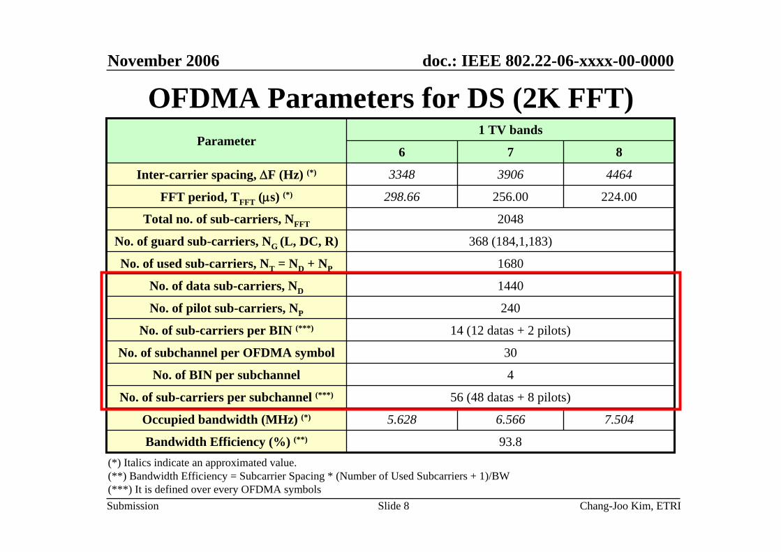
OFDMA Parameters for DS (2K FFT)
30No. of subchannel per OFDMA symbol
4No. of BIN per subchannel
14 (12 datas + 2 pilots)No. of sub-carriers per BIN (***)
56 (48 datas + 8 pilots)No. of sub-carriers per subchannel (***)
240No. of pilot sub-carriers, NP
7.5046.5665.628Occupied bandwidth (MHz) (*)
93.8Bandwidth Efficiency (%) (**)
1440No. of data sub-carriers, ND
1680No. of used sub-carriers, NT = ND + NP
368 (184,1,183)No. of guard sub-carriers, NG (L, DC, R)
2048Total no. of sub-carriers, NFFT
224.00256.00298.66FFT period, TFFT (μs) (*)
446439063348Inter-carrier spacing, ΔF (Hz) (*)
876
1 TV bandsParameter
(*) Italics indicate an approximated value.(**) Bandwidth Efficiency = Subcarrier Spacing * (Number of Used Subcarriers + 1)/BW(***) It is defined over every OFDMA symbols

November 2006
Chang-Joo Kim, ETRISlide 9
doc.: IEEE 802.22-06-xxxx-00-0000
Submission
Preamble Pattern
• Two repetitions within one OFDMA symbol• GI=1/4 (fixed)• Preamble shall be modulated using BPSK modulation• Used in channel estimation and initial synchronization
GI
NFFT/2 NFFT/2
NSYM

November 2006
Chang-Joo Kim, ETRISlide 10
doc.: IEEE 802.22-06-xxxx-00-0000
Submission
Preamble Pattern• Preamble sequence
• PN sequence generator
– Initial states of PN sequence generator: 10001010100– Note that PN sequence has the order of 11 so that the period of
preamble sequence is 2047.• 840 chips (half of 1680) are used for each preamble
⎩⎨⎧ <≤=−
=otherwise
NmmkDkP usedmT 0
,4/0,2)21(2)(
⎩⎨⎧ <≤+=−
=otherwise
NmNmkDkP usedusedmT 0
2/4/,12)21(2)(
1)( 211 ++= xxxg

November 2006
Chang-Joo Kim, ETRISlide 11
doc.: IEEE 802.22-06-xxxx-00-0000
Submission
Pilot Pattern for DS• Pilot Structure
for Extendable Channel Estimation
• Available Pilot Pattern for Channel Estimation
Pilot
Data
frequency
time
RepetitionUnit
BIN
OFDMA Symbol
CopyCopy
CopyCopyCopyCopyCopyCopy
CopyCopyCopyCopy

November 2006
Chang-Joo Kim, ETRISlide 12
doc.: IEEE 802.22-06-xxxx-00-0000
Submission
OFDMA Parameters for US (2K FFT)
70No. of subchannel per OFDMA symbol
8No. of BIN per subchannel
9 (6 datas + 3 pilots)No. of sub-carriers per BIN (***)
72 (48 datas + 24 pilots)No. of sub-carriers per subchannel (***)
560No. of pilot sub-carriers, NP
7.5046.5665.628Occupied bandwidth (MHz) (*)
93.8Bandwidth Efficiency (%) (**)
1120No. of data sub-carriers, ND
1680No. of used sub-carriers, NT = ND + NP
368 (184,1,183)No. of guard sub-carriers, NG (L, DC, R)
2048Total no. of sub-carriers, NFFT
224.00256.00298.66FFT period, TFFT (μs) (*)
446439063348Inter-carrier spacing, ΔF (Hz) (*)
876
1 TV bandsParameter
(*) Italics indicate an approximated value.(**) Bandwidth Efficiency = Subcarrier Spacing * (Number of Used Subcarriers + 1)/BW(***) It is defined over 3 OFDMA symbols

November 2006
Chang-Joo Kim, ETRISlide 13
doc.: IEEE 802.22-06-xxxx-00-0000
Submission
Pilot Pattern in US• BIN structure with pilot pattern
• The subchannel is composed of 8 BINs• The rule of Diversity subchannel is similar to PUSC
mode of 16e US
PilotData
time
OFDMA Symbol
frequency

November 2006
Chang-Joo Kim, ETRISlide 14
doc.: IEEE 802.22-06-xxxx-00-0000
Submission
Short Burst Traffic in US
• The US short burst is very possible because of an asymmetric traffic pattern
• If the US burst is too short for pilot to visit all subcarriers, the performance of channel estimation is getting worse.
• The pilots should be inserted more densely to deal with the short burst traffic in up stream.

November 2006
Chang-Joo Kim, ETRISlide 15
doc.: IEEE 802.22-06-xxxx-00-0000
Submission
Shared Subchannel Case between CPEs• In this case, the BS cannot use the US preamble for
channel estimation of CPE.
frame n-1 frame n frame n+1 ...Time
...
MAC Slot Number
Pre
ambl
e
FCH
DS
-MA
PU
S-M
AP
Sel
f-co
exis
tenc
e
Ranging
UCS Notification
Burst CPE #4
Burst CPE #2
Burst CPE #1
Burst CPE #5
Burst CPE #3
Burst CPE #7
Burst CPE #1
Burst CPE #2
Burst CPE #4
Burst CPE #5
Burst CPE #3
Burst CPE #6
Burst CPE #8
Burst CPE #9
Sel
f-co
exis
tenc
e
Burst CPE #6
Burst CPE #7
Burst CPE #8
TTG
k k+1 k+3 k+5 k+7 k+9 k+11 k+13 k+15 k+17 k+20 k+23 k+26 k+29
TV Channel N
TV Channel N+1
DS US
Logi
cal M
AC
Cha
nnel
Num
ber
s
s+1
s+2
s+L
BW Request
RTG

November 2006
Chang-Joo Kim, ETRISlide 16
doc.: IEEE 802.22-06-xxxx-00-0000
Submission
Channel Estimation in US
• To reduce the performance loss of channel estimation due to the short burst and shared subchannel, we propose that the allocation unit to CPE be composed of 3 OFDMA symbols (same as PUSC mode in 16e US)
• The pilot symbol visits every subcarriers over 3 OFDMA symbols
• Using 3 OFDMA symbols, we can obtain optimum performance of channel estimation without interpolation between pilots

November 2006
Chang-Joo Kim, ETRISlide 17
doc.: IEEE 802.22-06-xxxx-00-0000
Submission
Decision Procedure of Preamble and Pilot Pattern
Yes No
Is it possible to achieve the sufficient performancesin initial synchronization using proposed preamble only?
Yes
Is it possible to achieve the sufficient performancesin tracking without pilots?
No
Reinforce the preamble!
Reinforce the preamble& Remove all pilots
Maintain (or slightly modify)the proposed preamble and pilots
Is it possible to achieve the sufficient performancesin channel estimation using proposed preamble only?
No
Use one preamble symbol& Remove all pilots
Yes
Is it possible to achieve the sufficient performancesin channel estimation using proposed preamble and pilots?
Yes No
Reinforce the preambleand(or) the pilots
If we assume the phase noise model with PSD(0)=-100 dBc/Hz, the answer is ‘Yes’. However, if the phase noise effect becomes more severe, the answer may be ‘No’.
E.g. preamble of 2 OFDMA symbols without pilots
Even though the answer is ‘Yes’, we can leave vendors a choice to improve the performance in the point of phase noise tracking.

November 2006
Chang-Joo Kim, ETRISlide 18
doc.: IEEE 802.22-06-xxxx-00-0000
Submission
Subchannelization

November 2006
Chang-Joo Kim, ETRISlide 19
doc.: IEEE 802.22-06-xxxx-00-0000
Submission
Why We Need Two Types of Subchannel?
• In general, distributed subcarrier permutations perform very well in mobile applications or severe frequency selective environments,
• While adjacent subcarrier permutations can be properly used for fixed applications or flat fadingenvironments.
Subcarrier Allocation
Diversity SubchannelDiversity Subchannel AMC SubchannelAMC Subchannel

November 2006
Chang-Joo Kim, ETRISlide 20
doc.: IEEE 802.22-06-xxxx-00-0000
Submission
Diversity Subchannelization for DS• Symbol structure of Diversity subchannel in DS
– All the pilot subcarriers are allocated first– And then the remaining subcarriers are used exclusively for data transmission– To allocate data subchannels, the remaining subcarriers are grouped into the
number of data subcarriers per BIN, Nsubcarrier (=12)– The number of the subcarriers in a group is equal to the number of BINs, Nbin
(=120)– Thus, the number of data subcarriers is equal to Nsubcarrier*Nbin (=12*120)– The subcarrier index of subcarrier k in BIN b is according to following equation
subcarrier(k,b)=Nbin*k+Nsubchannel*(b%4)+int(b/4)• where,
b is the index of BIN, from 0 to Nbin-1k is the index of subcarrier in BIN, from 0 to Nsubcarrier-1Nsubchannel is the number of subchannel in one OFDMA symbol, equal to 30int(x) is the integer value of x
– The Diversity subchannel consists of 4 contiguous BINs– The BIN structure is a set of 12 distributed data subcarriers and 2 pilot subcarriers
within an OFDMA symbol

November 2006
Chang-Joo Kim, ETRISlide 21
doc.: IEEE 802.22-06-xxxx-00-0000
Submission
GROUP#0
GROUP#1
GROUP#2
GROUP#
11
Rem
aini
ng s
ubca
rrie
rs a
fter
pilo
t al
loca
tion
120
subc
arri
ers
BIN#0
BIN#1
BIN#2
BIN#3
BIN#4
BIN#
119
SUBCHANNEL#0
SUBCHANNEL#29
BIN#
116
BIN#
117
BIN#
118
1439
1350
13211320
359
270
241
240239
150
121120119
301
0 01
2
11
48 s
ubca
rrie
rs
Diversity Subchannelization for DS (Cont.)

November 2006
Chang-Joo Kim, ETRISlide 22
doc.: IEEE 802.22-06-xxxx-00-0000
Submission
Diversity Subchannelization for US• Symbol structure of Diversity subchannel in US
– The frequency band is divided into the number of BINs, Nbin (=560)– Divide the 560 BINs into eight groups, containing 70 adjacent BINs– The choice of 8 BINs to subchannel is according to following equation
BIN(s,n)=70*n+Pt[(s+n)mod 70]• where,
n is the index of BIN, from 0 to 7Pt is the tile permutations is the subchannel number
– After allocating the BINs for each subchannel, the data subcarriers per subchannel are enumerated by the following process:
– After allocating the pilot carriers within each BIN, data subcarriers is indexed from 0 to 47– The mapping of data into the subcarriers will follow equation
subcarrier(n,s)=(n+13*s) mod 48• where,
n is the running index, from 0 to 47, indicating the data constellation points is the subchannel number
– The Diversity subchannel consists of 8 distributed BINs– The BIN structure is a set of 6 data subcarriers and 3 pilot subcarriers within 3 OFDMA symbol
November 2006
Chang-Joo Kim, ETRISlide 23
doc.: IEEE 802.22-06-xxxx-00-0000
Submission
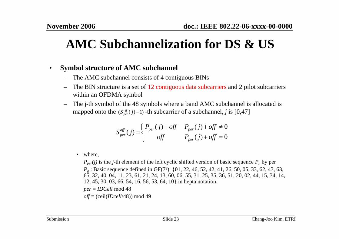
AMC Subchannelization for DS & US
• Symbol structure of AMC subchannel– The AMC subchannel consists of 4 contiguous BINs– The BIN structure is a set of 12 contiguous data subcarriers and 2 pilot subcarriers
within an OFDMA symbol– The j-th symbol of the 48 symbols where a band AMC subchannel is allocated is
mapped onto the -th subcarrier of a subchannel, j is [0,47]
• where,Pper(j) is the j-th element of the left cyclic shifted version of basic sequence P0 by perP0 : Basic sequence defined in GF(72): {01, 22, 46, 52, 42, 41, 26, 50, 05, 33, 62, 43, 63, 65, 32, 40, 04, 11, 23, 61, 21, 24, 13, 60, 06, 55, 31, 25, 35, 36, 51, 20, 02, 44, 15, 34, 14, 12, 45, 30, 03, 66, 54, 16, 56, 53, 64, 10} in hepta notation.per = IDCell mod 48off = (ceil(IDcell/48)) mod 49
)1)(( −jS offper
⎩⎨⎧
=+≠++
=0)(0)()(
)(offjPoffoffjPoffjP
jSper
perperoffper

November 2006
Chang-Joo Kim, ETRISlide 24
doc.: IEEE 802.22-06-xxxx-00-0000
Submission
Mixed Resource Composition
t
f
t
f
: AMC 1 [Bin 1]: AMC 0 [Bin 0] : Diversity 1: Diversity 0
t
f
t
fSubcarrier-unit mixturewith frequency hopping
BIN-unit mixturewith frequency hopping
Subcarrier-unit mixturewithout frequency hopping
BIN-unit mixturewithout frequency hopping
• 4 Types of Different Resource Composition in DL
Type II
Type I Type III
Type IV
November 2006
Chang-Joo Kim, ETRISlide 25
doc.: IEEE 802.22-06-xxxx-00-0000
Submission
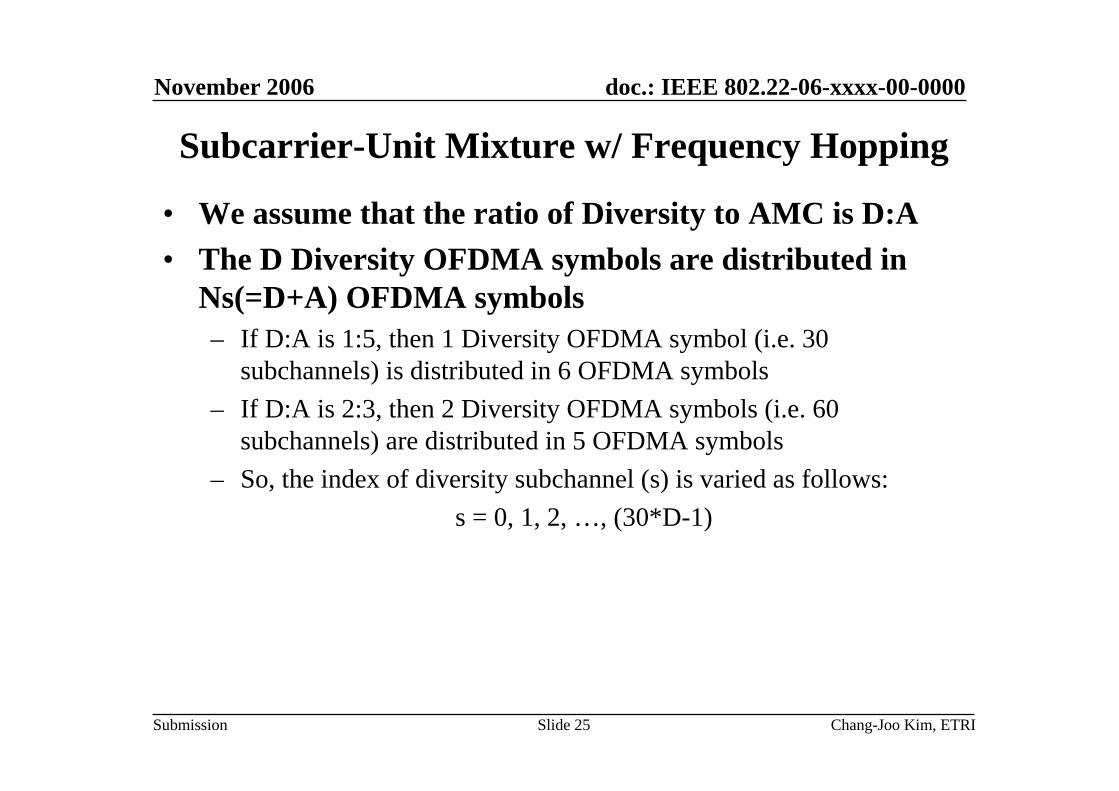
Subcarrier-Unit Mixture w/ Frequency Hopping
• We assume that the ratio of Diversity to AMC is D:A• The D Diversity OFDMA symbols are distributed in
Ns(=D+A) OFDMA symbols– If D:A is 1:5, then 1 Diversity OFDMA symbol (i.e. 30
subchannels) is distributed in 6 OFDMA symbols– If D:A is 2:3, then 2 Diversity OFDMA symbols (i.e. 60
subchannels) are distributed in 5 OFDMA symbols– So, the index of diversity subchannel (s) is varied as follows:
s = 0, 1, 2, …, (30*D-1)

November 2006
Chang-Joo Kim, ETRISlide 26
doc.: IEEE 802.22-06-xxxx-00-0000
Submission
Subcarrier-Unit Mixture w/ Frequency Hopping
• The subcarrier index of subcarrier j in subchannel s is according to following equation
– where,j is the index of subcarrier in subchannel, from 0 to 47s is the index of subchannel, from 0 to (30*D-1)fs(0) is the first index of subcarrier in subchannel
• fs(0) is defined as follows:
– where, BRO(x) is Bit Reversal Order of x, and a is the GCD(Ns,30)
• fs(j) is allocated to ts-th OFDMA symbol
47,...,2,1,0,30)0()( =+= jjfjf ss
⎣ ⎦)30/())30,(mod()0( assBROfs +=
),mod( ss Nst =

November 2006
Chang-Joo Kim, ETRISlide 27
doc.: IEEE 802.22-06-xxxx-00-0000
Submission
Example of Subcarrier-Unit Mixture (D:A=1:5)
...
D A
Logical Mapping
OFDM#0
Physical Mapping
OFDM #D+A-1OFDM#1 OFDM#2
Ns,sl=D+A
Sch#0
Sch#1
Sch#29
Sch#2
Sch#3
Sch#4
S=0
S=1
S=29
S=1
S=0
S=2

November 2006
Chang-Joo Kim, ETRISlide 28
doc.: IEEE 802.22-06-xxxx-00-0000
Submission
Algorithms &Operation Procedure

November 2006
Chang-Joo Kim, ETRISlide 29
doc.: IEEE 802.22-06-xxxx-00-0000
Submission
Top Block Diagram of WRAN PHY Simulator
RandomizerEncoderPuncturer
&Interleaver
MapperSubcarrierAllocator S/P
Preamble&
PilotInsertion
IFFT
GuardInsertionP/S
AWGN
Channel
De-randomizerDecoder
De-interleaver&Depuncturer
De-mapper
SubcarrierDeallocator P/SChannel
Estimation
FFT
GuardRemovalS/P
Synchronization
FromMAC
ToMAC
Superframe&
FrameEncoder
Superframe&
FrameDecoder
Frequency&TimingOffset
)(kX i)(nxi
)(tx
)(ty
)(kYi)(nyi

November 2006
Chang-Joo Kim, ETRISlide 30
doc.: IEEE 802.22-06-xxxx-00-0000
Submission
Signal Model for Synchronization• Transmitted signal
• Received signal with carrier frequency offset (CFO)
• The time-sampled version of the received signal
• Demodulated symbol at the k-th subcarrier in the i-thOFDM symbol
spacing subcarrier theis /1 where,))(()()(1
0
))((2 TfTiTtpekXtxN
kGSYM
TiTtfkji
i
Gsym =Δ+−= ∑∑−
=
+−Δ∞
−∞=
π
offsetfrequency carrier theis ,,)()()()( 0
1
0
2 fwheretwethtxtyM
m
tfjmm
o +−= ∑−
=
πτ
timesampling theiswhere,,)()(~)( 2S
nTfj Tnwenyny So += π
)()()()( )(2 0 kWkHkXeekY iiijTNiNfj
iSGSYM +⋅⋅= + θπ

November 2006
Chang-Joo Kim, ETRISlide 31
doc.: IEEE 802.22-06-xxxx-00-0000
Submission
Timing Synchronization• With the Schmidl’s method
– Autocorrelation method using the following
– The metric
– Timing
∑
∑−
=
−
=
+=
=+++=
1
0
2
1
0
*
|)(|)(
)2/( ,)()()( where
D
n
D
n
ndydM
NDDndyndydP
)(max dTMtdo =
So NTfjenyNny π)()2
( =+
)(|)(|)(
dMdPdTM =

November 2006
Chang-Joo Kim, ETRISlide 32
doc.: IEEE 802.22-06-xxxx-00-0000
Submission
Timing Synchronization• Enhanced timing metric
– to resolve the timing ambiguity in the plateau– to protect the timing outside the guard interval
∑−=
+=2/
2/)()(
W
WwwdTMdNM
)(max dNMtdo =

November 2006
Chang-Joo Kim, ETRISlide 33
doc.: IEEE 802.22-06-xxxx-00-0000
Submission
CFO(FFO+IFO) Estimation• When the timing is obtained, the received samples
corresponding to the preamble are given by
• FFO estimates using Preamble in time-domain
⎟⎟⎠
⎞⎜⎜⎝
⎛= −
))(Re())(Im(tan1ˆ
0
01
tPtP
f πε
Tf
T o1ˆ1
≤<−
πεπ jNTfj y(n)ey(n)e)Ny(n So ==+ 2/
∑∑−
=
−
=
=+=12/
0
212/
0
* |)(|)2/()((N
n
jN
no enyNnyny)tP πε
1ˆ1 ≤<− fε

November 2006
Chang-Joo Kim, ETRISlide 34
doc.: IEEE 802.22-06-xxxx-00-0000
Submission
CFO(FFO+IFO) Estimation
• Two components in the CFO
– Only the FFO can be estimated in the time domain
• Integral frequency offset (IFO) estimation– After compensating , the FFT output is given by
(IFO) offsetfrequency Integral : (FFO) offsetfrequency Fractional
μμμμε
ε
εεε
,1,...,1,0,...,1,
:11
2
−+−−=
≤<−
+==
i
f
fioTf
fε
Nnjj
i
o eenxy(n)πε
θ4
)(= oji ekXkY θε )2()( −=FFT

November 2006
Chang-Joo Kim, ETRISlide 35
doc.: IEEE 802.22-06-xxxx-00-0000
Submission
CFO(FFO+IFO) Estimation• IFO estimation
– We can obtain the IFO using the correlation of the PN sequence
• Total CFO estimation range:
μμ ≤≤−++++
=
∑
∑
∈
∈ gkY
gkPkYgkPkYgF
c
c
Sk
TSk
T
,|)(|
)2()()22()2()(
2
**
|)(|maxˆ gFgi μμ
ε≤≤−
=
12ˆ12 +≤<−− μεμ

November 2006
Chang-Joo Kim, ETRISlide 36
doc.: IEEE 802.22-06-0248-00-0000
Submission
CFO(FFO+IFO) Estimation Range• Requirements on the CFO estimation
– BS : 2 ppm– CPE : 8 ppm
• Worst case scenario– BS - CPE : 10 ppm at the frequency of 862 MHz – CFO estimation up to -8.62 kHz ~ 8.62 kHz
• Estimation with the proposed preamble– Estimation range in the time domain: -3.348 kHz ~ 3.348 kHz– We should estimate IFO in (-2 ,2) (1 PN offset)– Even though the proposed method can estimate the IFO up to 682,
we set the estimation range as (-8, 8) at the receiver.

November 2006
Chang-Joo Kim, ETRISlide 37
doc.: IEEE 802.22-06-xxxx-00-0000
Submission
FFO Tracking Algorithms Using GI• FFO estimation using GI in the time-domain
• FFO estimates using GI in the time-domain
⎟⎟⎠
⎞⎜⎜⎝
⎛= −
)Re()Im(tan
21ˆ 1
γγ
πε f
Tf
T o 21ˆ
21
≤<−
πεπ 22 jNTfj y(n)ey(n)eN)y(n So ==+
∑∑−
=
−
=
=+=1
0
221
0
* |)(|)()(GG N
n
jN
nenyNnyny πεγ
5.0ˆ5.0 ≤<− fε

November 2006
Chang-Joo Kim, ETRISlide 38
doc.: IEEE 802.22-06-xxxx-00-0000
Submission
FFO Tracking Algorithms Using Pilots• FFO estimation using Pilot in the frequency-domain
• FFO estimates using Pilot in the frequency-domain
where, RG is the ratio of GI size to FFT size
SSYM
SGSYM
TNfjii
iiijTNiNfj
i
ekYkkY
kWkHkXeekY0
0
21
)(2
)()(
)()()()(π
θπ
≈Δ+
+⋅⋅=
+
+
[ ]
symbolOFDMadjacenttheinpilotsbetweenspacingsubcarriertheisandpilot,ththeofindextheiswhere,
)()()(1
0
221
01
* 0
kn a
ekYkaYaY
n
N
n
TNfji
N
nnini
PSSYM
P
Δ
=Δ+= ∑∑−
=
−
=+
πγ
⎟⎟⎠
⎞⎜⎜⎝
⎛+
= −
)Re()Im(tan
)1(21ˆ 1
γγ
πε
Gf R
4848.0ˆ4848.0 max, ≤<− fε

November 2006
Chang-Joo Kim, ETRISlide 39
doc.: IEEE 802.22-06-xxxx-00-0000
Submission
Channel Estimation• Received Signal Vector
– Y: received signal vector in the frequency domain– X: diagonal matrix containing data symbols– W: AWGN
• At Pilot Positions
XP: diagonal matrix containing pilot symbolsHP: channel response at pilot positions
WXHY +=
PPPP WHXY +=

November 2006
Chang-Joo Kim, ETRISlide 40
doc.: IEEE 802.22-06-xxxx-00-0000
Submission
LMMSE Channel Estimation• Linear minimum mean-squared error (LMMSE)
estimation– Minimizes the mean-squared error between the channel response
and . – High computational complexity but good performance.
• To reduce the complexity in LMMSE estimation, low-rank approximations or partitioned LMMSE may be used.
H H

November 2006
Chang-Joo Kim, ETRISlide 41
doc.: IEEE 802.22-06-xxxx-00-0000
Submission
LMMSE Channel Estimation• Wiener - Hopf Equation
– Assume that the estimator is constrained to be a linear function of . – The problem is to find the matrix K that minimizes the mean-squared
error between and the linear estimator .– The necessary and sufficient condition for the mean-squared error to be
minimized is for the estimation error to be orthogonal to each input sample, which is expressed by the Wiener-Hopf equation.
where is the noisey pilot estimates, is the variance of the channel noise Wp , and RPP is the autocovariance matrix of the noiseless pilots.
H
H PY
PKYH =ˆ
[ ] PYYHYlmmseYYHYH
PP YRRHRRKYKYHEPPPPPP
11 ˆ0)( −− =→=→=−
[ ][ ] IXRXYYER
XRHYER
nHPPPP
HPPYY
HPPH
HPHY
PP
P
2
ˆ
σ+==
==
2nσp

November 2006
Chang-Joo Kim, ETRISlide 42
doc.: IEEE 802.22-06-xxxx-00-0000
Submission
LMMSE Channel Estimation• LMMSE(Linear Minimum Mean-Squared Error) Estimates
where,
– It also requires to know the covariance matrix of the channel and the average SNR.
[ ]( )[ ]
lsPPPH
lsHPPnPPPH
PnHPPPP
HPPH
PYYHYlmmse
HISNR
RR
HXXRR
YIXRXXR
YRRHPPP
ˆ
ˆ
ˆ
1
ˆ
112ˆ
12ˆ
1
−
−−
−
−
⎥⎦⎤
⎢⎣⎡ +=
+=
+=
=
β
σ
σ
T
N
NPPls
P
P
XY
XY
XYYXH
⎥⎥⎦
⎤
⎢⎢⎣
⎡==
−
−−
1
1
1
1
0
01 ...ˆ
[ ] [ ]22 /1 kk XEXE=β [ ] 22 / nkXESNR σ=

November 2006
Chang-Joo Kim, ETRISlide 43
doc.: IEEE 802.22-06-xxxx-00-0000
Submission
Synchronization & Ch. Estimation Procedure
IFO estimation
PreambleTiming Synchronization
FFO estimation
FFO tracking
Channel Estimation

November 2006
Chang-Joo Kim, ETRISlide 44
doc.: IEEE 802.22-06-xxxx-00-0000
Submission
Simulation Conditions

November 2006
Chang-Joo Kim, ETRISlide 45
doc.: IEEE 802.22-06-xxxx-00-0000
Submission
Simulation Conditions• Channel coding
– 802.16e convolutional coding– Code rate: 1/2, 2/3, 3/4, 5/6
• Modulation– Data: QPSK, 16QAM, 64QAM– Preamble, Pilot: BPSK– No boosting
• FFT size and GI ratio– FFT size: 2K– GI ratio: 1/4
• Subchannelization– No. of used subcarriers for 2K: 1680 (30 subchannels x 56 subcarriers)– Subchannel type: Diversity & AMC

November 2006
Chang-Joo Kim, ETRISlide 46
doc.: IEEE 802.22-06-xxxx-00-0000
Submission
Simulation Conditions• Channel Modeling
– AWGN– Multipath profiles & Doppler: A, B, C, D
• Approximation to nearest sampling point• Jakes Rayleigh modeling method
16.527(*)5.6921.9562.772RMS Delay Spread (us)
DCBAMultipath Profile
(*) For WRAN profile D, we assume that the 6-th path has the excess delay of 60 us and relative power of -10 dB

November 2006
Chang-Joo Kim, ETRISlide 47
doc.: IEEE 802.22-06-xxxx-00-0000
Submission
Simulation Conditions• Channel Modeling
– Multipath profiles & Doppler• Channel response of WRAN multipath profile
The span of 10 subcarriers

November 2006
Chang-Joo Kim, ETRISlide 48
doc.: IEEE 802.22-06-xxxx-00-0000
Submission
Simulation Conditions• Coherent bandwith vs. Nyquist rate
– Two ray model: one ray has 0 us delay, another ray has 33 us delay– The rms delay spread is 33/2=16.5 us, from the definition– 90% coherent BW is 1.21 kHz, from 1/(50*rms delay spread)– 50% coherent BW is 12.1 kHz, from 1/(5*rms delay spread)
-20
-15
-10
-5
0
5
-0.5 -0.4 -0.3 -0.2 -0.1 0 0.1 0.2 0.3 0.4 0.5
Subcarrier index (normalized to FFT size)
Channel re
sponse
(dB)
-20
-15
-10
-5
0
5
0.129 0.13 0.131 0.132 0.133 0.134 0.135 0.136
Subcarrier index (normalized to FFT size)
Channel re
sponse
(dB)
The span of 10 subcarriers
90% coherent bandwidth(=1.21 kHz)
50% coherent bandwidth(=12.1 kHz)

November 2006
Chang-Joo Kim, ETRISlide 49
doc.: IEEE 802.22-06-xxxx-00-0000
Submission
Simulation Conditions• Phase Noise : Commercial Specifications
R Company-90 dBc/Hz @ 10 kHz470 ~ 860 MHzDVB-T(OFDM)
P Company-80 dBc/Hz @ 1 kHz-87 dBc/Hz @ 10 kHz470 ~ 862 MHzDVB-T(OFDM)
R Company-85 dBc/Hz @ 10 kHz40 ~ 870 MHzDVB-T(OFDM)
R Company
-80 dBc/Hz @ 1 kHz-91 dBc/Hz @ 10 kHz
-102 dBc/Hz @ 100 kHz-128 dBc/Hz @ 1 MHz
470 ~ 860 MHzDVB-T(OFDM)
2.4 or 5 GHz
50.5 ~ 858 MHz
Frequency Range
IEEE 802.11 TGnwhere, PSD(0)=-100 dBc/Hz,fp=250 kHz, fz=7905.7 kHz
WLAN(OFDM)
S Company-80 dBc/Hz @ 1 kHz-80 dBc/Hz @ 10 kHz
-105 dBc/Hz @ 100 kHzDVB-T(OFDM)
CompanySpecificationsApplication
])/(1[])/(1[)0()( 2
2
p
z
ffffPSDfPSD
++
=
SimulationModel

November 2006
Chang-Joo Kim, ETRISlide 50
doc.: IEEE 802.22-06-xxxx-00-0000
Submission
Simulation Conditions• Phase Noise : PSD
-110
-105
-100
-95
-90
-85
-80
-75
0.0E+00 2.5E+04 5.0E+04 7.5E+04 1.0E+05 1.3E+05 1.5E+05
Frequency
PSD
(dB
c/H
z)
Commercial Specification
IEEE 802.11 TGn Model

November 2006
Chang-Joo Kim, ETRISlide 51
doc.: IEEE 802.22-06-xxxx-00-0000
Submission
Simulation Conditions• Phase Noise : Instantaneous Phase Error

November 2006
Chang-Joo Kim, ETRISlide 52
doc.: IEEE 802.22-06-xxxx-00-0000
Submission
Simulation Conditions• Phase Noise
– 64QAM constellations with phase noise
• Carrier frequency offset (CFO) : 8.62 kHz
(a) Ideal (b) IEEE 802.11 TGn model (c) Commercial specification
Constellation [64QAM]
-1.5
-1.0
-0.5
0.0
0.5
1.0
1.5
-1.5 -1.0 -0.5 0.0 0.5 1.0 1.5
Inphase
Qua
drat
ure
Constellation [64QAM]
-1.5
-1.0
-0.5
0.0
0.5
1.0
1.5
-1.5 -1.0 -0.5 0.0 0.5 1.0 1.5
Inphase
Qua
drat
ure
Constellation [64QAM]
-1.5
-1.0
-0.5
0.0
0.5
1.0
1.5
-1.5 -1.0 -0.5 0.0 0.5 1.0 1.5
Inphase
Qua
drat
ure

November 2006
Chang-Joo Kim, ETRISlide 53
doc.: IEEE 802.22-06-xxxx-00-0000
Submission
Simulation Results1. Missing probability of preamble starting point2. MSE of CFO estimate (in acquisition)3. MSE of FFO estimate (in tracking)4. Uncoded BER of LMMSE estimation5. Performance comparison for calculation method of covariance matrix6. Performance comparison for frequency offset effect7. Performance comparison for preamble and pilot pattern8. Performance comparison for phase noise9. Uncoded/Coded Bit/Block error rate performance under ideal channel estimation10. Performance of mixed resource composition
November 2006
Chang-Joo Kim, ETRISlide 54
doc.: IEEE 802.22-06-xxxx-00-0000
Submission
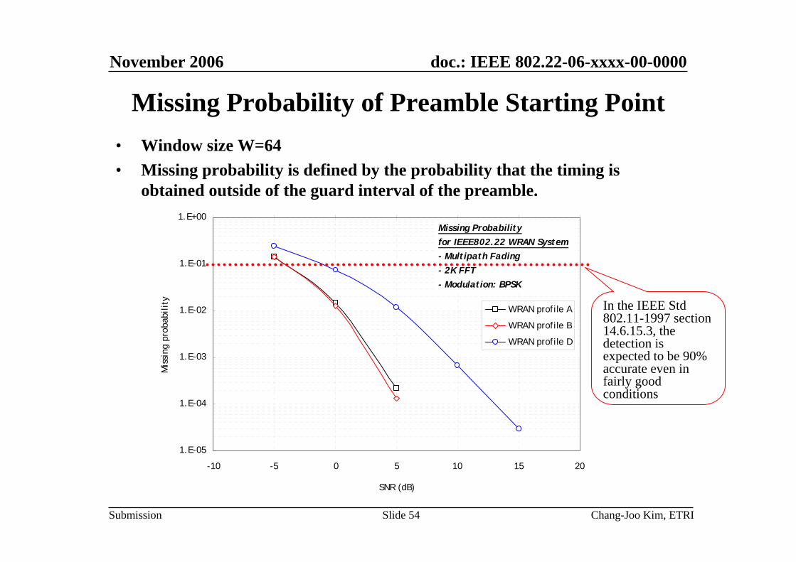
Missing Probability of Preamble Starting Point• Window size W=64• Missing probability is defined by the probability that the timing is
obtained outside of the guard interval of the preamble.
1.E-05
1.E-04
1.E-03
1.E-02
1.E-01
1.E+00
-10 -5 0 5 10 15 20
SNR (dB)
Mis
sing
pro
babi
lity
WRAN profile A
WRAN profile B
WRAN profile D
Missing Probabilityfor IEEE802.22 WRAN System- Multipath Fading- 2K FFT- Modulation: BPSK
In the IEEE Std 802.11-1997 section 14.6.15.3, the detection is expected to be 90% accurate even in fairly good conditions

November 2006
Chang-Joo Kim, ETRISlide 55
doc.: IEEE 802.22-06-xxxx-00-0000
Submission
MSE of FFO Estimate (Using DS Preamble)
• }|ˆ{| 2ffEMSE εε −=
1.E-07
1.E-06
1.E-05
1.E-04
1.E-03
1.E-02
1.E-01
1.E+00
1.E+01
-10 -5 0 5 10 15 20 25 30 35
SNR (dB)
MSE
WRAN profile A
WRAN profile B
WRAN profile D
MSE of FFO Estimatefor IEEE802.22 WRAN System- Multipath Fading- 2K FFT- Modulation: BPSK
November 2006
Chang-Joo Kim, ETRISlide 56
doc.: IEEE 802.22-06-xxxx-00-0000
Submission
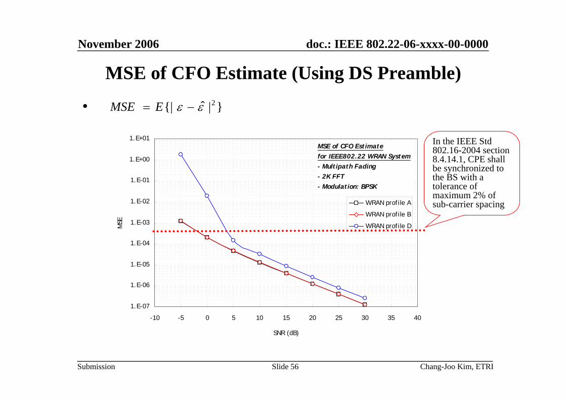
MSE of CFO Estimate (Using DS Preamble)
• }|ˆ{| 2εε −= EMSE
1.E-07
1.E-06
1.E-05
1.E-04
1.E-03
1.E-02
1.E-01
1.E+00
1.E+01
-10 -5 0 5 10 15 20 25 30 35 40
SNR (dB)
MSE
WRAN profile A
WRAN profile B
WRAN profile D
MSE of CFO Estimatefor IEEE802.22 WRAN System- Multipath Fading- 2K FFT- Modulation: BPSK
In the IEEE Std 802.16-2004 section 8.4.14.1, CPE shall be synchronized to the BS with a tolerance of maximum 2% of sub-carrier spacing

November 2006
Chang-Joo Kim, ETRISlide 57
doc.: IEEE 802.22-06-xxxx-00-0000
Submission
Assumptions for FFO Tracking Simulation• Residual frequency offset: 2% of subcarrier spacing• 2 algorithms for FFO tracking
– Using guard interval– Using pilot
• Consider the phase noise model in IEEE 802.11 TGncomparison criteria
• 2K FFT size & GI ratio of 1/4

November 2006
Chang-Joo Kim, ETRISlide 58
doc.: IEEE 802.22-06-xxxx-00-0000
Submission
MSE of FFO Estimate (Using GI or Pilot)
1.E-06
1.E-05
1.E-04
1.E-03
1.E-02
1.E-01
1.E+00
1.E+01
-10 -5 0 5 10 15 20 25 30 35
SNR (dB)
MSE
WRAN profile A(GI)WRAN profile B(GI)WRAN profile C(GI)WRAN profile D(GI)WRAN profile A(PILOT)WRAN profile B(PILOT)WRAN profile C(PILOT)WRAN profile D(PILOT)
MSE of FFO Estimatefor IEEE802.22 WRAN System- Multipath Fading- 2K FFT- CP Ratio: 1/4- Modulation: QPSK
Using guard interval
Using pilot 2% ofsub-carrier spacing

November 2006
Chang-Joo Kim, ETRISlide 59
doc.: IEEE 802.22-06-xxxx-00-0000
Submission
Assumptions for Channel Estimation Simulation• 3 Types of Partitioned LMMSE
– LMMSE, 1 : Channel estimation using the pilot of each OFDM symbol– LMMSE, 3 : Channel estimation using the pilot of 3 OFDM symbols– LMMSE, 7 : Channel estimation using the pilot of 7 OFDM symbols
• Apply the partitioned LMMSE to reduce the complexity in LMMSE estimation (Subcarrier size = 56).
• Calculation method of covariance matrix– Method 1: Pre-calculation assuming exponential model– Method 2: Real-time calculation using actual measured model
• No channel coding employed• Initial frequency offset: 2KHz
– Assume that the CFO estimation using preamble is successful (< 2% of subcarrier spacing)
– Fine frequency offset tracking loop is ON

November 2006
Chang-Joo Kim, ETRISlide 60
doc.: IEEE 802.22-06-xxxx-00-0000
Submission
Uncoded BER Performance (Profile A, QPSK)

November 2006
Chang-Joo Kim, ETRISlide 61
doc.: IEEE 802.22-06-xxxx-00-0000
Submission
Uncoded BER Performance (Profile A, 64QAM)

November 2006
Chang-Joo Kim, ETRISlide 62
doc.: IEEE 802.22-06-xxxx-00-0000
Submission
Uncoded BER Performance (Profile C, QPSK)

November 2006
Chang-Joo Kim, ETRISlide 63
doc.: IEEE 802.22-06-xxxx-00-0000
Submission
Uncoded BER Performance (Profile C, 64QAM)

November 2006
Chang-Joo Kim, ETRISlide 64
doc.: IEEE 802.22-06-xxxx-00-0000
Submission
Uncoded BER Performance (Profile D, QPSK)

November 2006
Chang-Joo Kim, ETRISlide 65
doc.: IEEE 802.22-06-xxxx-00-0000
Submission
Uncoded BER Performance (Profile D, 64QAM)

November 2006
Chang-Joo Kim, ETRISlide 66
doc.: IEEE 802.22-06-xxxx-00-0000
Submission
Performance Comparison for Calculation Method of Covariance Matrix (Profile C, QPSK)
November 2006
Chang-Joo Kim, ETRISlide 67
doc.: IEEE 802.22-06-xxxx-00-0000
Submission
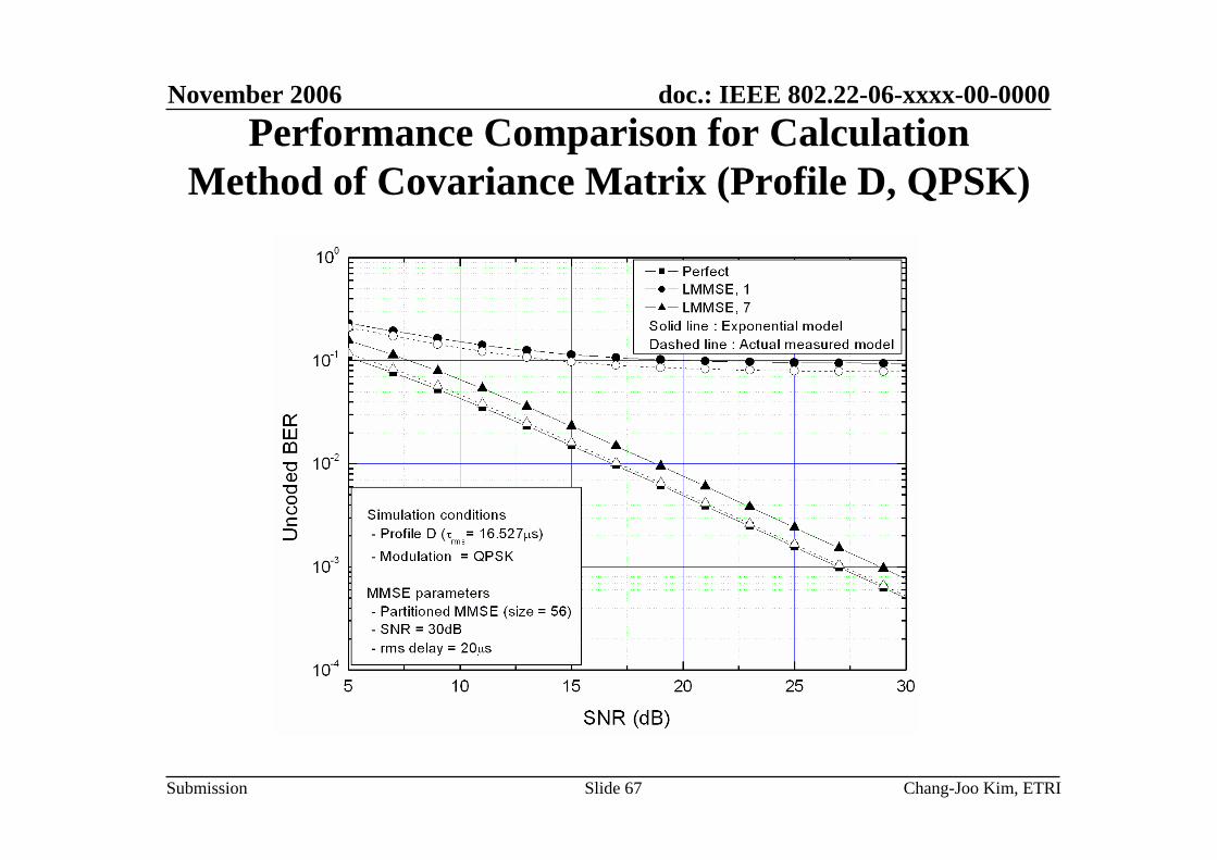
Performance Comparison for Calculation Method of Covariance Matrix (Profile D, QPSK)

November 2006
Chang-Joo Kim, ETRISlide 68
doc.: IEEE 802.22-06-xxxx-00-0000
Submission
Performance Comparisonfor Frequency Offset Effect (Profile A, QPSK)

November 2006
Chang-Joo Kim, ETRISlide 69
doc.: IEEE 802.22-06-xxxx-00-0000
Submission
Performance Comparisonfor Frequency Offset Effect (Profile A, 64QAM)

November 2006
Chang-Joo Kim, ETRISlide 70
doc.: IEEE 802.22-06-xxxx-00-0000
Submission
Performance Comparisonfor Preamble/Pilot Pattern (Profile A, QPSK)

November 2006
Chang-Joo Kim, ETRISlide 71
doc.: IEEE 802.22-06-xxxx-00-0000
Submission
Performance Comparisonfor Preamble/Pilot Pattern (Profile C, QPSK)

November 2006
Chang-Joo Kim, ETRISlide 72
doc.: IEEE 802.22-06-xxxx-00-0000
Submission
Performance Comparisonfor Preamble/Pilot Pattern (Profile D, QPSK)

November 2006
Chang-Joo Kim, ETRISlide 73
doc.: IEEE 802.22-06-xxxx-00-0000
Submission
Performance Comparison for Phase Noise (Profile A, 64QAM, Preamble w/ Pilot)

November 2006
Chang-Joo Kim, ETRISlide 74
doc.: IEEE 802.22-06-xxxx-00-0000
Submission
Performance Comparison for Phase Noise (Profile D, 64QAM, Preamble w/ Pilot)

November 2006
Chang-Joo Kim, ETRISlide 75
doc.: IEEE 802.22-06-xxxx-00-0000
Submission
Performance Comparison for Phase Noise (Profile A, 64QAM, 2 Symbol Preamble only)

November 2006
Chang-Joo Kim, ETRISlide 76
doc.: IEEE 802.22-06-xxxx-00-0000
Submission
Performance Comparison for Phase Noise (Profile D, 64QAM, 2 Symbol Preamble only)

November 2006
Chang-Joo Kim, ETRISlide 77
doc.: IEEE 802.22-06-xxxx-00-0000
Submission
Uncoded/Coded Bit Error Rate in AWGN
1.0E-07
1.0E-06
1.0E-05
1.0E-04
1.0E-03
1.0E-02
1.0E-01
1.0E+00
0 2 4 6 8 10 12 14 16
SNR(dB)
Bit
Erro
r R
ate(
Log
Scal
e)
Text
Simulation
QPSK
16QAM
64QAM
Coded Bit ER Performancesfor IEEE802.22 WRAN System- AWGN Environments
- 2K FFT- Convolutional Coding(16d)- Code Rate: 1/2- Encoded Block Size: 36 Bytes
Text: R. Van Nee et al., "OFDM for Wireless
Multimedia Communications," Artech House
Publishers, 2000.
1.0E-07
1.0E-06
1.0E-05
1.0E-04
1.0E-03
1.0E-02
1.0E-01
1.0E+00
0 5 10 15 20 25 30
SNR(dB)
Bit
Erro
r R
ate(
Log
Scal
e)
Theory
Simulation
QPSK
16QAM
64QAM
Uncoded Bit ER Performances
for IEEE802.22 WRAN System- AWGN Environments- 2K FFT
November 2006
Chang-Joo Kim, ETRISlide 78
doc.: IEEE 802.22-06-xxxx-00-0000
Submission
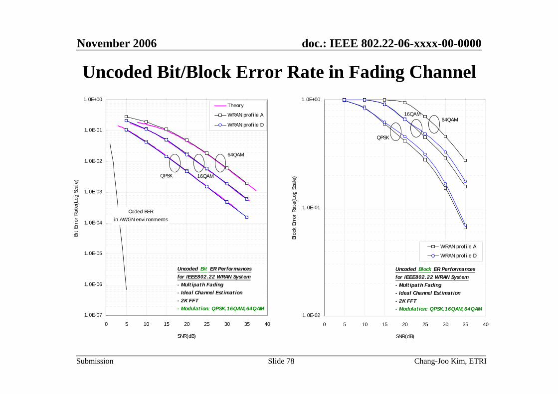
Uncoded Bit/Block Error Rate in Fading Channel
1.0E-07
1.0E-06
1.0E-05
1.0E-04
1.0E-03
1.0E-02
1.0E-01
1.0E+00
0 5 10 15 20 25 30 35 40
SNR(dB)
Bit
Erro
r R
ate(
Log
Scal
e)
Theory
WRAN profile A
WRAN profile D
Coded BER
in AWGN environments
Uncoded Bit ER Performancesfor IEEE802.22 WRAN System- Multipath Fading- Ideal Channel Estimation- 2K FFT- Modulation: QPSK,16QAM,64QAM
QPSK 16QAM
64QAM
1.0E-02
1.0E-01
1.0E+00
0 5 10 15 20 25 30 35 40
SNR(dB)
Bloc
k Er
ror
Rat
e(Lo
g Sc
ale)
WRAN profile A
WRAN profile D
Uncoded Block ER Performancesfor IEEE802.22 WRAN System- Multipath Fading- Ideal Channel Estimation- 2K FFT- Modulation: QPSK,16QAM,64QAM
QPSK
64QAM16QAM

November 2006
Chang-Joo Kim, ETRISlide 79
doc.: IEEE 802.22-06-xxxx-00-0000
Submission
Assumptions for Mixed Resource Composition• IEEE 802.22 WRAN multipath profile A• 2K FFT• Number of data subcarriers per BIN = 12• One subchannel consists of 48 data subcarriers• Perfect channel estimation • Convolutional code (CC) and convolutional turbo code
(CTC) are used for channel coding• No phase noise• No frequency offset

November 2006
Chang-Joo Kim, ETRISlide 80
doc.: IEEE 802.22-06-xxxx-00-0000
Submission
Performances of Mixed Resource Composition
0 1 2 3 4 510-4
10-3
10-2
10-1
100 Nep=288, CC, QPSK, CR=1/2, K=7
Es/No
PE
R
TYPE IVTYPE IIITYPE IITYPE IAWGN

November 2006
Chang-Joo Kim, ETRISlide 81
doc.: IEEE 802.22-06-xxxx-00-0000
Submission
0 1 2 3 4 510-6
10-5
10-4
10-3
10-2
10-1
100 Nep=288, CC, QPSK, CR=1/2, K=7
Es/No
BE
R
TYPE IVTYPE IIITYPE IITYPE IAWGN
Performances of Mixed Resource Composition

November 2006
Chang-Joo Kim, ETRISlide 82
doc.: IEEE 802.22-06-xxxx-00-0000
Submission
0 2 4 6 810-6
10-5
10-4
10-3
10-2
10-1
100 Nep=288, CTC, QPSK, CR=1/2
Es/No
PE
R
TYPE IVTYPE IIITYPE IITYPE IAWGN
Performances of Mixed Resource Composition

November 2006
Chang-Joo Kim, ETRISlide 83
doc.: IEEE 802.22-06-xxxx-00-0000
Submission
0 2 4 6 810-8
10-6
10-4
10-2
100 Nep=288, CTC, QPSK, CR=1/2
Es/No
BE
R
TYPE IVTYPE IIITYPE IITYPE IAWGN
Performances of Mixed Resource Composition

November 2006
Chang-Joo Kim, ETRISlide 84
doc.: IEEE 802.22-06-xxxx-00-0000
Submission
Conclusions• From the simulations of initial synchronization
– In the WRAN profile A, B, and C, we obtain 90% preamble detection probability at -4 dB SNR.
– Even in the WRAN profile D, we obtain 90% preamble detection probability at -2 dB SNR
– In the WRAN profile A, B, and C, we can synchronize the CPE to the BS within 2 % of sub-carrier spacing at -2 dB SNR
– Even in the WRAN profile D, we can synchronize the CPE to the BS within 2 % of sub-carrier spacing at 4 dB SNR

November 2006
Chang-Joo Kim, ETRISlide 85
doc.: IEEE 802.22-06-xxxx-00-0000
Submission
Conclusions• From the simulations of FFO tracking
– The performance using guard interval is better than that using pilot. Here, we assume the GI ratio of 1/4, i.e. 512 subcarriers for 2K FFT size.
– The performance difference is because the correlation size is different, the number of GI subcarriers is 512 and the number of pilot subcarriers is 240.
– Another reason is because the pilot in adjacent OFDM symbol has experienced the different channel distortion from the pilot in the previous OFDM symbol.

November 2006
Chang-Joo Kim, ETRISlide 86
doc.: IEEE 802.22-06-xxxx-00-0000
Submission
Conclusions• From the simulations of LMMSE channel estimation
– If 7 OFDM symbols are used in LMMSE estimation, there are the performance degradation of 0.2~0.5 dB and 2.0~2.5 dB compared to ideal channel estimation for profile A and D, respectively. If 1 or 3 OFDM symbols are used in LMMSE estimation, there are huge performance loss.
– Therefore, to prevent huge performance loss, it is necessary forpilot symbol to visit every subcarriers. It will be established using preamble and scattered pilot.
– Regarding the calculation method of covariance matrix, the real-time calculation using actual measured model has a much better performance than that of pre-calculation assuming exponential model. Even though the complexity is increasing, because the WRAN system is fixed, we can decrease the complexity by stopping the training of channel information after several frames.

November 2006
Chang-Joo Kim, ETRISlide 87
doc.: IEEE 802.22-06-xxxx-00-0000
Submission
Conclusions• From the simulations of LMMSE channel estimation
(Cont’d)– If we use the frequency offset tracking, the performance loss due to
residual frequency offset is ignorable.– The performance using two preamble alone (without pilots) is
similar to the performance using 7 OFDMA symbols (with pilots).– Below the SNR of about 25dB, the Gaussian noise is dominant.
However, above the SNR of about 25dB, the phase noise is dominant.
– We can reduce the effect of constant phase error (CPE) and inter-carrier interference (ICI) due to phase noise by using scatteredpilots.

November 2006
Chang-Joo Kim, ETRISlide 88
doc.: IEEE 802.22-06-xxxx-00-0000
Submission
Conclusions• From the simulations of mixed resource composition
– Among four types of mixed resource composition, the subcarrier-unit mixture with frequency hopping has the best performance.
– The subcarrier allocation method is similar as conventional Diversity subchannel, except the adjacent subchannel is allocated to adjacent OFDMA symbol
– When we use convolutional code, we can achieve the improvement above the SNR of 3dB
– We can achieve the more improvements by using the convolutionalturbo code than convolutional code