220/33kv switchyard for kishanganga (3x110mw) hep … file1. 33kv, 1-ph voltage transformer no. 15...
TRANSCRIPT

NHPC Limited Bharat Heavy Electricals Ltd. 220/33kV Switchyard for Kishanganga (3x110MW) HEP Doc. No. TB-329-510-006 Technical Specification for 33kV Voltage Transformer Rev. No. 01
1 of 3
SECTION 1
SCOPE, SPECIFIC TECHNICAL REQUIREMENTS & QUANTITIES
1.0 SCOPE
This specification covers requirements of design, engineering, manufacture, assembly, testing at works, inspection, packing and dispatch of 33kV Voltage Transformers along with its accessories as mentioned in this section and in various other sections of this specification for 220/33kV switchyard at Kishanganga (HEP) In case of any conflict among the various sections of this specification, then the order of precedence shall be Section-1, Section-2 & then Section -3
1.1 CUSTOMER / PROJECT DETAIL
Name of customer : NHPC Limited. Name of the project : 220/33kV Switchyard for Kishanganga (3x110MW) HEP Kishanganga Consortium : Hindustan Construction Company (HCC)
Refer Section - 3 for Project Details and General Specifications. 1.2 SPECIFIC TECHNICAL REQUIREMENTS:-
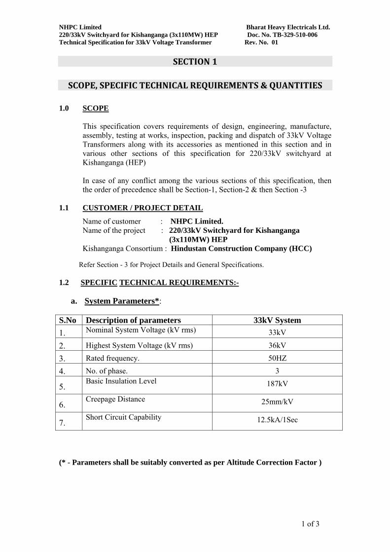
a. System Parameters*: S.No Description of parameters 33kV System 1. Nominal System Voltage (kV rms) 33kV
2. Highest System Voltage (kV rms) 36kV
3. Rated frequency. 50HZ
4. No. of phase. 3
5. Basic Insulation Level 187kV
6. Creepage Distance 25mm/kV
7. Short Circuit Capability 12.5kA/1Sec
(* - Parameters shall be suitably converted as per Altitude Correction Factor )
NHPC Limited Bharat Heavy Electricals Ltd. 220/33kV Switchyard for Kishanganga (3x110MW) HEP Doc. No. TB-329-510-006 Technical Specification for 33kV Voltage Transformer Rev. No. 01
2 of 3
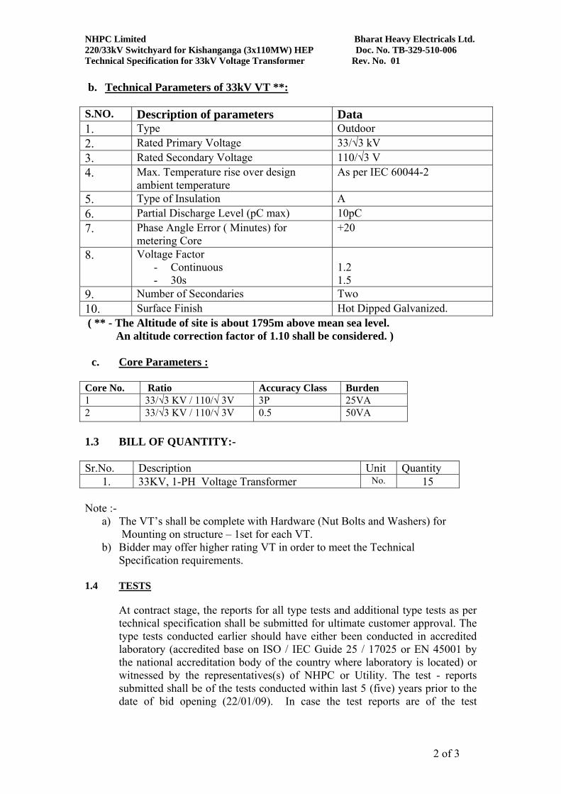
b. Technical Parameters of 33kV VT **:
S.NO. Description of parameters Data 1. Type Outdoor 2. Rated Primary Voltage 33/√3 kV 3. Rated Secondary Voltage 110/√3 V 4. Max. Temperature rise over design
ambient temperature As per IEC 60044-2
5. Type of Insulation A 6. Partial Discharge Level (pC max) 10pC 7. Phase Angle Error ( Minutes) for
metering Core +20
8. Voltage Factor - Continuous - 30s
1.2 1.5
9. Number of Secondaries Two 10. Surface Finish Hot Dipped Galvanized. ( ** - The Altitude of site is about 1795m above mean sea level. An altitude correction factor of 1.10 shall be considered. )
c. Core Parameters : Core No. Ratio Accuracy Class Burden 1 33/√3 KV / 110/√ 3V 3P 25VA 2 33/√3 KV / 110/√ 3V 0.5 50VA 1.3 BILL OF QUANTITY:-
Sr.No. Description Unit Quantity
1. 33KV, 1-PH Voltage Transformer No. 15 Note :-
a) The VT’s shall be complete with Hardware (Nut Bolts and Washers) for Mounting on structure – 1set for each VT.
b) Bidder may offer higher rating VT in order to meet the Technical Specification requirements.
1.4 TESTS
At contract stage, the reports for all type tests and additional type tests as per technical specification shall be submitted for ultimate customer approval. The type tests conducted earlier should have either been conducted in accredited laboratory (accredited base on ISO / IEC Guide 25 / 17025 or EN 45001 by the national accreditation body of the country where laboratory is located) or witnessed by the representatives(s) of NHPC or Utility. The test - reports submitted shall be of the tests conducted within last 5 (five) years prior to the date of bid opening (22/01/09). In case the test reports are of the test

NHPC Limited Bharat Heavy Electricals Ltd. 220/33kV Switchyard for Kishanganga (3x110MW) HEP Doc. No. TB-329-510-006 Technical Specification for 33kV Voltage Transformer Rev. No. 01
3 of 3
conducted earlier than 5 (five) years prior to the date of bid opening, the bidder shall repeat these test(s) at no extra cost to the BHEL. In the event of any discrepancy in the test reports i.e. any test report not acceptable to customer due to any design / manufacturing changes (including substitution of components) or due to non-compliance with the requirement stipulated in the Technical Specification on any/all additional type tests not carried out, same shall be carried out without any additional cost implication to the BHEL.
1.5 QUALIFYING REQUIREMENTS The Subcontractors should have manufactured, type tested & supplied similar size of equipments during last ten (10) years. The equipment so manufactured should have been successfully commissioned at least at three power stations /sub stations. 1.6 DEVIATIONS :
The bidder shall list all the deviation from the specification separately. Offers without specific deviation will be deemed to be totally in compliance with the specification and NO DEVIATION on any account will be entertained at a later date.
1.7 MANUFACTURING QUALITY PLAN:
Bidder has to follow NHPC approved Manufacturing Quality Plan at contract stage.

NHPC Limited Bharat Heavy Electricals Ltd. 220/33kV Switchyard for Kishanganga (3x110MW) HEP Doc. No. TB-329-510-006 Technical Specification for 33kV Voltage Transformer Rev. No. 01
1 of 4
SECTION 2
EQUIPMENT SPECIFICATION
2.0 SCOPE
This technical specification covers the requirements of design, manufacture, testing at works, packing and dispatch of Voltage Transformer (VT). In case of any discrepancies between requirements mentioned in this section and those mentioned in Section-3 of this specification, this Section shall prevail and shall be treated as binding requirement. No deviation from the requirements specified in various clauses of this specification will be allowed.
2.1 APPLICABLE STANDARDS
The equipment covered under the package shall conform to the requirements of the latest edition of the relevant IEC/IS Specifications or equivalent National Standards. The IEC/IS Specifications and international publication relevant to the equipment covered under this specification shall include but not be limited to the list given below:
Voltage transformers IEC 60044, IS: 3156 Insulating oil IS:335 2.2 GENERAL
The AC Instrument Transformers and accessories shall conform to the latest version of IEC60044/ IS: 3156. The instrument transformers provided for control, metering and protective relaying functions shall have accuracy ratings and burden capabilities adequate to provide their designated functions within the overall accuracy requirements of the systems. The instrument transformers shall be designed for use in geographical and meteorological condition as specified in Section III of this Specification . The specification given below relates to oil filled instrument transformers.
2.3 TECHNICAL AND CONSTRUCTIONAL REQUIREMENTS
The features and constructional details of Voltage transformers shall be in accordance with requirements stipulated hereunder:
2.3.1 Bushing/Insulators: a) Voltage Transformer shall be of 33kV class, oil filled, with shedded
porcelain bushings/ Insulators suitable for outdoor service and upright mounting on steel structures.

NHPC Limited Bharat Heavy Electricals Ltd. 220/33kV Switchyard for Kishanganga (3x110MW) HEP Doc. No. TB-329-510-006 Technical Specification for 33kV Voltage Transformer Rev. No. 01
2 of 4
b) Bushings/Insulators shall conform to requirements of Clause 2.4 below.
c) VT tank shall be provided with oil filling and drain plugs, oil sight
glass. d) Instruments transformers shall be hermetically sealed units.
Manufacturer shall furnish details of the arrangements made for the sealing of instrument transformers.
e) Polarity marks shall indelibly be marked on each instrument
transformer and at the lead terminals at the associated terminal block.
2.3.2 Terminal box/Marshalling box:
Each single phase instrument transformers shall be complete with its terminal box. The terminal box shall meet the requirements of IP55 as per IS-13947 Part-I.
2.3.3 Insulating Oil: Insulating oil to be used for instrument transformers shall be of EHV grade and shall conform to IS: 335 (required for first filling) and IEC60296.
2.3.4 Tank The tank along with top metallics shall be hot dip galvanized or painted As per Clause 3.10 of Section III.
2.3.5 Lifting arrangement Voltage transformers shall be provided with suitable lifting arrangement, to lift the entire unit. The lifting arrangement shall be clearly shown in the general arrangement drawing.
2.3.6 Name Plate: Nameplate shall conform to the requirements of IEC incorporating the year of manufacture. The rated Voltage and voltage factor shall be clearly indicated on the nameplate.
2.4 SPECIFIC TECHNICAL REQUIREMENT
a) The secondaries shall be protected by HRC cartridge type fuses for all
windings In addition fuses shall also be provided for protection and metering windings for connection to fuse monitoring scheme. The secondary terminals shall be terminated on stud type non-disconnecting terminal blocks via the fuse inside the individual phase secondary terminal box of degree of protection IP: 55 . The access to secondary terminals shall be without the danger of access to high voltage circuit.

NHPC Limited Bharat Heavy Electricals Ltd. 220/33kV Switchyard for Kishanganga (3x110MW) HEP Doc. No. TB-329-510-006 Technical Specification for 33kV Voltage Transformer Rev. No. 01
3 of 4
b) Accuracy of 0.5 on Secondary II shall be maintained throughout the entire burden range of 50VA on all windings, without any adjustments during operation. The VTs shall be thermally and dielectrically safe when the secondary terminals are loaded with guaranteed thermal burdens.
c) The protection cores shall not saturate at about 1.5 times the rated voltage for a min. duration of 30 secs.
d) The expansion chamber at the top of the porcelain insulators should be suitable for expansion of oil.
e) The voltage transformer shall be suitable for horizontal transportation. It shall
be ensured that the VT is able to withstand all the stresses imposed on it while transporting and there shall be no damage in transit.
f) Super enameled wire shall preferably be used for secondary windings. Copper
conductor shall be used for all windings. 2.5 TYPE & ROUTINE TESTS 2.5.1 The voltage transformer shall be type tested as per the requirements of
IEC:60044-2/ IS 3156.
2.5.2 The VTs shall be subjected to routine tests IEC-60044-2/ IS 3156.
2.6 BUSHINGS AND SUPPORT INSULATORS 2.6.1 GENERAL
Bushings shall be manufactured and tested in accordance with IEC-60137 and IS-2099 & IS-3347 while hollow column insulators shall be manufactured and tested in accordance with IEC-233 and IS-5284. The support insulators shall be manufactured and tested as per IEC-60168, IEC-60273 and IS-2544. The insulators shall also conform to IEC-60815 as applicable.
All bushings shall be one piece only and no joints shall be accepted. If joint is unavoidable on a bushing, the Contractor shall seek Employer's approval on a case to case basis.
2.6.2 CONSTRUCTIONAL FEATURES
a) Porcelain used shall be homogeneous and free from imperfections that might affect the mechanical or dielectric quality.
b) Glazing of the porcelain shall be of uniform brown colour, free from blisters, burns and other similar defects. The ground surface shall not be glazed.
c) Condenser type bushing shall be provided with :

NHPC Limited Bharat Heavy Electricals Ltd. 220/33kV Switchyard for Kishanganga (3x110MW) HEP Doc. No. TB-329-510-006 Technical Specification for 33kV Voltage Transformer Rev. No. 01
4 of 4
i) Oil level gauge. ii) Oil filling plug and drain valve if not hermetically sealed. iii) Tap for capacitance and tan delta test.
d) When bushings have an under-oil end of re-entrant form, the pull through lead shall be fitted with a gas bubble deflector.
e) Where Voltage transformers are specified, the bushings shall be removable without disturbing the Voltage transformers.
f) Bushings of identical rating shall be interchangeable.
g) No arching horns shall be provided on the bushings.
h) All ferrous parts shall be hot dip galvanized. All joints shall be air tight. Insulator/bushing design shall be such as to ensure a uniform compressive pressure on the joints.
i) Support insulators/bushings/hollow column insulators shall be designed to have ample insulation, mechanical strength and rigidity for the conditions under which they shall be used.
j) When operating at rated voltage there shall be no electric discharge between conductor and insulators which would cause damage to conductors or insulators by the formation of substances produced by chemical action. No radio interference shall be caused when operating at rated voltage.
k) The design of the insulator shall be such that stresses due to expansion and contraction in any part of the insulator shall not lead to deterioration.
l) The manufacturer shall define the type of insulator (type A or B) as per IEC-60168.
m) Bushing porcelain shall be robust and capable of withstanding the internal pressures likely to occur in service. The design and location of clamps and the shape and the strength of the porcelain flange securing the bushing to the tank shall be such that there is no risk of fracture. All portions of the assembled porcelain enclosures and supports other than gaskets, which may in any way be exposed to the atmosphere shall be composed of completely non hygroscopic material such as metal or glazed porcelain.
n) Special precaution shall be taken to exclude moisture from paper insulation during manufacture, assembly, transport and erection. The surface of all paper insulation shall be finished with non-hygroscopic varnish which cannot be damaged easily.
2.6.3 TESTS Each type of bushing and insulator shall be subjected to type and routine
tests in accordance with applicable standards.

220/33kV Switchyard for Kishanganga (3x110MW) HEP Client: NHPC Limited KISHANGANGA CONSORTIUM: Hindustan Construction Company (HCC) Ltd., HALCROW
___________________________________________________________________________ Page 1 of 19
SECTION - 3
PROJECT DETAILS AND GENERAL SPECIFICATIONS 3.0 INTRODUCTION
Kishanganga Hydroelectric project (3x110=330MW) is located in Baramulla district of Jammu and Kashmir state of India. As a part of the project, 220/33 kV Switchyard is being carried out.
3.1 PROJECT INFORMATION
SL.NO
DESCRIPTION
a) Customer NATIONAL HYDRO ELECTRIC POWER CORPORATION LIMITED (NHPC) KISHANGANGA CONSORTIUM: Hindustan Construction Company (HCC) Ltd. HALCROW Subcontractor: Bharat Heavy Electricals Ltd. (BHEL)
b) Project 220/33kV Switchyard for Kishanganga (3x110MW) HEP
c) Project locations Kishanganga Hydroelectric project(3x110=330MW) is located in Baramulla district of Jammu and Kashmir state of India. Refer Project Details from Contract Specification attached herewith.
d) Nearest Airport Srinagar is the nearest city, well connected by Air. e) Nearest Railway station /Gauge
Distance from Railway StationJammu is the nearest broad guage railway head
f) Road Approach
Refer Project Details from Contract Specification attached herewith.
Transport Limit Refer Project Details from Contract Specification attached herewith.
3.2 SITE CONDITIONS
SL.NO
DESCRIPTION
i. Altitude About 1795 m above mean sea level. ii. Seismic Zone Refer Project Details from Contract Specification
attached herewith. iii. Rainfall (Average annual
rainfall) Refer Project Details from Contract Specification attached herewith.
iv. AMBIENT AIR Refer Project Details from Contract Specification

220/33kV Switchyard for Kishanganga (3x110MW) HEP Client: NHPC Limited KISHANGANGA CONSORTIUM: Hindustan Construction Company (HCC) Ltd. , HALCROW
___________________________________________________________________________ Page 2 of 19
TEMPERATURE (a) Max. temp (b) Min. temp
attached herewith.
v. RELATIVE HUMIDITY (a) Maximum (b) Minimum
Refer Project Details from Contract Specification attached herewith.
vi. Temperature zone Refer Project Details from Contract Specification attached herewith.
Equipment to be supplied against this specification shall be suitable for satisfactory continuous operation under the above tropical conditions:
3.2.1 Auxiliary Supply Auxiliary electrical equipment pertaining to this project shall be suitable for operation at the following supply system.
Normal Voltage
Variation in Voltage
Frequency (Hz)
Phase/Wire Neutral Connection
415 Volts ± 10% 50 ± 5% 3/4 wire Grounded neutral 240 Volts ± 10% 50 ± 5% ½ effectively earthed 220 Volts ± 10% DC 2 wire Ungrounded, with earth
fault detection 48 Volts ± 10% DC 2 wire Ungrounded, with earth
fault detection Combined variation of voltage and frequency shall be limited to ± 10%.
3.3 INSPECTION, TESTING AND INSPECTION CERTIFICATE All equipment being supplied shall conform to type tests and shall be subject to routine tests in accordance with relevant standards.
All tests and inspection of the equipment specified shall be performed to the extent and in the manner as stipulated in the relevant standards and in this specification. All type test/routine tests/acceptance tests as specified shall be conducted in the presence of BHEL/NHPC. Wherever equipment similar to the one being offered has already been type tested in an independent government laboratory or in the presence of representative of State Electricity Board or other reputed public undertakings, Type test reports of the same shall be submitted for approval of BHEL /NHPC.
If these are not found technically acceptable, contractor will have to carry out the type test without any extra cost and/ or delivery implications in presence of BHEL/NHPC.
Where specified by the purchaser, type tests will have to be conducted by the sub-contractor on the equipment in the scope of supply. Such test shall be witnessed by the customer and BHEL, for which the test charges and delivery implications if any shall be indicated separately by the sub-contractor.
The contractor shall give the Owner/Inspector 3 week’s written notice of any material being ready for inspection/testing. Such tests shall be to the Contractor's account except for the
220/33kV Switchyard for Kishanganga (3x110MW) HEP Client: NHPC Limited KISHANGANGA CONSORTIUM: Hindustan Construction Company (HCC) Ltd. , HALCROW
___________________________________________________________________________ Page 3 of 19
expenses' of the Inspector.
The purchaser NHPC/BHEL or their authorized representative shall have at all reasonable times free access to the contractor’s works and shall have the power at all reasonable times to inspect the material and workmanship of the works during manufacturing or erection if part of the works is being manufactured or assembled at other premises. Inspection may be made at any stage of manufacture, dispatch or at site at the option of NHPC/BHEL and the equipment if found unsatisfactory due to bad workmanship or quality is liable to be rejected.
When the factory tests have been completed at the subcontractor's works the Owner/Inspector shall issue a certificate to this effect after completion of tests. But if the tests are not witnessed by the Owner/lnspector, the waival shall be issued by the Owner/Inspector within fifteen (15) days of the receipt of the Contractor's test certificate. Failure of the Owner/Inspector to issue such a waival shall not prevent the contractor from proceeding with the works. The completion of these tests or the issue of the waival shall not bind the Owner to accept the equipment should it, on further tests after erection be found not to comply with the Contract. However, in case of waivals, the contractor shall ensure to carry out the testing as per approved quality plans and specification requirements and send two copies of all the test results to the Owner for his review and approval.
In all cases where the Contract provides for tests at the premises or works of the contractor, the contractor, except were otherwise specified shall provide free of charge such items as labor materials, electricity, fuel; water, stores, apparatus and instruments as may be reasonably demanded by Owner/Inspector or his authorized representatives to carry out such tests.
The Inspection by Employer and issue of inspection Certificate thereon shall in no way limit the liabilities and responsibilities of the Contractor in respect of the agreed quality assurance programme forming a part of the contract.
The owner will have the right of having at his own expenses any other test(s) of reasonable nature carried out at contractor premises or at site or in any other place in addition of aforesaid type and routine tests, to satisfy that the material comply with the specification.
The Employer reserves the right for getting any field tests conducted on the completely assembled equipment at site.
3.4 QUALITY ASSURANCE PROGRAMME
The supplier should adopt suitable quality assurance programme to control all necessary activities to ensure that the equipment and / or services under the scope are in accordance with this specification. A quality plan detailing out the specific quality measure and procedures adopted for controlling the quality characteristics to be submitted for BHEL and NHPC approval.
The quality programme is defined by ISO 9001, 1994 Quality systems - Model for quality assurance in design, development, production, installation and servicing.
3.5 DOCUMENTATION

220/33kV Switchyard for Kishanganga (3x110MW) HEP Client: NHPC Limited KISHANGANGA CONSORTIUM: Hindustan Construction Company (HCC) Ltd. , HALCROW
___________________________________________________________________________ Page 4 of 19
The Contractor shall submit a detailed list of all drawings he proposes to submit for approval/information after the award of the contract. This list shall be revised and extended, as necessary, during the progress of work.
All drawings submitted by the Contractor shall be in sufficient detail to indicate the type, size, arrangement weight of' each component, breakdown for packing and shipment, the external connections, fixing arrangements required, the dimensions required for installation and interconnections with other equipment land materials. clearances and spaces required between various portions of equipment and any other information specifically requested.
After the award of the Contract, the Contractor shall submit, (as per the Distribution Schedule enclosed at the end of this section as a Table) copies of design basis reports/concept notes, design calculations, material specifications and detailed drawings as called for in the Contract for the Owner's / Owner's, Representative review. The Contractor must satisfy the Owner's / Owner's Representative as to the validity of his design with reference to the requirements of Statutory Codes / Authorities, local regulations and the contract specifications.
All dimensions on drawings shall be in Metric Units, unless otherwise specified. The details in the drawings shall be in English language only.
Drawings submitted by the Contractor will be checked/reviewed by the Owner/Engineer and comments, if any, on the same will be conveyed to the Contractor. It is the responsibility of the Contractor to incorporate correctly all the comments conveyed by the Owner/Engineer on the Contractor's drawings. The drawings which are approved with comments are to be resubmitted to the owner/Engineer for purpose of records. Such drawings will not be checked/reviewed by the Owner/Engineer to verify whether all the comments have been incorporated by the Contractor. If the Contractor is unable to incorporate certain comments in his drawings he shall clearly state in his forwarding letter such non-compliance along with valid reasons and justification.
The Contractor shall not be relieved of his obligations under the Contract if he has not included features in the specification, including but not limited to his Guarantee obligations stated herein, by incorporating the Owner's / Owner's Representative comments.
Any work performed or material ordered by the Contractor prior to receipt of drawings stamped 'Approved with comments as noted', by the Owner/Engineer Shall be at the risk of the Contractor. After print of any drawing has been returned 'Approved', the Contractor may release the parts covered by the drawing, for production.
Drawings prepared by the Contractor and approved by the Owner/Engineer shall be considered as a part of the Contract Specification. However, examination and approval of the drawings by the Qwner/Engineer shall not relieve the Contractor of his responsibility for engineering, design, workmanship, materials and construction under the Contract.
If, at any time before the completion of the work, changes are made necessitating revision of approved drawings, the Contractor shall make such revisions and proceed in the same routine as for the original approval.
3.5.1 OTHER REQUIREMENTS OF DOCUMENTATION Upon completion of the installation, the Contractor shall furnish a complete set of drawings on reproducible tracing film on which the VENDOR/Contractor shall make in a neat and

220/33kV Switchyard for Kishanganga (3x110MW) HEP Client: NHPC Limited KISHANGANGA CONSORTIUM: Hindustan Construction Company (HCC) Ltd. , HALCROW
___________________________________________________________________________ Page 5 of 19
accurate manner, a complete record of all changes and revisions to, the original design, as installed in the completed work. These drawings shall be submitted to the Owner/Engineer.
AS BUILT DRAWINGS The Contractor shall prepare and submit to the Owner/Engineer “As- Built drawings" of the Works, showing all Works as executed. The drawings shall be prepared as the Works proceed, and shall be submitted to owner/Engineer for his inspection. The Contractor shall obtain the consent of the Owner as to the drawing size, the referencing system and other pertinent details. The drawings/documents distribution schedule shall be as indicated below. The title block of drawings shall contain the following information incorporated in all contract drawings
CUSTOMER National Hydroelectric Power Corporation Limited (NHPC) PROJECT 220/33kV Switchyard for Kishanganga (3x110MW) HEP
KISHANGANGA CONSORTIUM: Hindustan Construction Company (HCC) Ltd. HALCROW Subcontractor: Bharat Heavy Electricals Ltd. (BHEL)
BHEL P.O. No. PROJ. DOC. No. REV. No. CONTRACTOR
BHARAT HEAVY ELECTRICALS LIMITED VENDOR’S STANDARD TITLE BLOCK
DOCUMENTS TO BE SUBMITTED ALONGWITH OFFER 1) Drawings 2) Guaranteed Technical Particulars 3) Type Test Reports 4) Manufacturing Quality Plan
DOCUMENTATION SCHEDULE AT CONTRACT STAGE A For Approval 7 (6+1) Copies of GA drawings with projects details, dimension, equipment weight,
fixing details, tolerances and terminal details etc. 7 (6+1) Copies of type test reports 7 (6+1) Copies of shipping list detailing the description & quantities of all items
being dispatched separately, with shipping weights, number of cases and dimensions.
7 (6+1) Copies of manufacturing and field quality plan. B After Approval and For Information/Distribution. 11 (10+1) Copies of All drawings plus 2 Set Reproducibles. 11 (10+1) Bound sets containing all ‘as built’ drawings/manuals, type and routine test
reports etc. along with sub-vendor’s test reports for all bought out assemblies/components/parts including Internal wiring diagrams and exploded diagrams of assemblies/ parts, shall be furnished plus 2 Set IR
11(10+1) Copies of Installation, Operation & Maintenance manual. 11(10+1) Sets of Spare parts catalogue. 5 Set of Computer CD-ROMs containing all ‘as-built’ drawings/documents.

220/33kV Switchyard for Kishanganga (3x110MW) HEP Client: NHPC Limited KISHANGANGA CONSORTIUM: Hindustan Construction Company (HCC) Ltd. , HALCROW
___________________________________________________________________________ Page 6 of 19
All the technical documents and drawings required to be furnished under this contract as per specification shall be prepared in internationally accepted software of latest version used for preparation of documents and drawings.
All the drawings and documents shall be submitted in presentable folders properly bound and catalogued for easy retrieval / reference. Drawings shall be submitted in A0 / A2 /A3 and all documentation in A4 size. All drawings shall be digitally printed/ plotted. Ammonia print/ blue print shall not be accepted.
Time schedule of drawings/documents required at contract stage shall be furnished by the supplier.
Material shall not be dispatched without the approval of test certificates by purchasers.
3.6 MATERIALS AND WORKMANSHIP 3.6.1. GENERAL REQUIREMENTS
Where the specification does not contain characteristics with reference to workmanship, equipment materials and component of the covered Equipment, it is understood that the same must be new, of highest .grade of the best quality of their kind, conforming to the best engineering practice and suitable for the purpose for which they are intended.
The equipment must be new, of highest grade, the best quality of their kind, to best engineering practice, latest state of ardent and in accordance with purpose for which they are intended and to ensure satisfactory performance throughout the service life.
Incase where the equipment material or components are indicated in the specification as “similar” to any special standard, the employer shall decide upon the question of similarity. When required by the specification or required by the employer the supplier shall submit, for approval, all the information concerning the material or components supplied, installed or used. Without such approval shall run the risk of subsequent rejection, it being understood that the cost as well as the time delay associated with the rejection shall be borne by the Supplier.
The design of the work shall be such that Installation, future expansions, replacement and general maintenance may be undertaken with a minimum of time and expenses. Each component shall be designed to be consistent with its duty and suitable factors of safety, subject to mutual agreements and shall be used throughout the design. All Joints and fastenings shall be devised, constructed and documented so that the component part shall be accurately positioned and retained to fulfill their required function. In general, screw threads shall be standard metric threads. The use of other thread forms will only be permitted when prior approval has been obtained from the Employer.
Whenever possible, all similar part of the works shall be made to gauge and shall also be made interchangeable with similar parts. All spare parts shall be interchangeable with, and shall be made of the same material and workmanship as the corresponding parts of the equipment supplied under specification. Where feasible, common component units shall be employed in different pieces of the equipment in order to minimize spare parts stocking

220/33kV Switchyard for Kishanganga (3x110MW) HEP Client: NHPC Limited KISHANGANGA CONSORTIUM: Hindustan Construction Company (HCC) Ltd. , HALCROW
___________________________________________________________________________ Page 7 of 19
requirements. All equipment of the same type and rating shall be physically and electrically interchangeable.
All material and equipment shall be installed in strict accordance with the manufacturer’s recommendation(s). Only first-class work in accordance with the best modern practice will be accepted. Installation shall be considered as being the erection of equipment at its permanent location. This, unless otherwise specified, shall Include unpacking, cleaning and lifting into position, grouping, leveling, aligning, coupling of or bolting down to previously installed equipment bases/ foundation, performing the alignment check and final adjusting prior to initial operation, testing and commissioning in accordance with the manufacturer’s tolerances and instruction and the specification. All factory assembled rotating machinery shall be checked for alignment and adjustments made as necessary to re-establish the manufacturer’s limits suitable guards shall be provided for the protection of personnel on all exposed rotating and/or moving machine parts and shall be designed for easy installation and removal for maintenance purpose. The spare equipment(s) shall be installed at designated location and tested for healthiness.
The Supplier shall apply oil and grease of the proper specification to suit the machinery, as is necessary for the installation of the equipment Lubricants used for installation purpose shall be drained out and the system flushed through where necessary for applying the lubricant required for operation. The Supplier shall apply all operational lubricants to the equipment installed by him.
All oil, grease and other consumables used in the Works/Equipment shall be purchased in India unless the Supplier has any special requirement for the specific application of a type of oil or grease not available in India. If such is the case he shall declare in the proposal, where such oil or grease is available. He shall help Employer in establishing equivalent India make and Indian supplier. The same shall be applicable to other consumables too.
A cast iron or welded steel base plate shall be provided for all rotating equipments which are to be installed on a concrete base unless otherwise agreed to by the Employer. Each base plate shall support the units and its drive assembly, shall be of design with pads for anchoring the units and shall have a raised up all around and shall have threaded in air connections, If so required.
All components exposed to rain shall be designed with sloped upper surface to avoid water pools.
3.7 CLAMPS AND CONNECTORS INCLUDING TERMINAL CONNECTORS All power clamps and connectors shall confirm to IS:5561 & NEMA CCI and shall be made of materials listed below:
a For connecting ACSR Aluminium alloy casting conforming to designation A6 of IS:617 and shall be tested for all test as per IS:617
b For connecting equipment terminals made of copper with ACSR conductors
Bimetallic connectors made from Aluminium alloy casting conforming to designation A6 of IS:617 with 2mm thick liner and shall be tested as per IS:617
c For connecting GI shield wire Galvanised mild steel

220/33kV Switchyard for Kishanganga (3x110MW) HEP Client: NHPC Limited KISHANGANGA CONSORTIUM: Hindustan Construction Company (HCC) Ltd. , HALCROW
___________________________________________________________________________ Page 8 of 19
d I) Bolts, nuts & plain washer galvanised
II) Spring washers for items ‘a’ to ‘c’
i) Electro galvanisation for sizes below Ml2, for others hot dip Galvanised ii) Electro Galvanised mild steel suitable for at least service condition-3 as per IS: 1573
Each equipment shall be supplied with the necessary terminals and connectors, as required by the ultimate design for the particular installation. The conductor termination of equipment shall be suitable for Twin/ single Zebra/ Moose ACSR Conductor with 250 mm Sub-Conductor spacing. The requirement regarding external RIV as specified for any equipment shall include its terminal fittings and the equipment shall be factory tested with the connectors in position
Where copper to aluminium connections are required, bi-metallic clamps shall be used, which shall be properly designed to ensure that any deterioration of the connection is kept to a minimum and restricted to parts which are not current carrying or subjected to stress. The design details of the joint shall be furnished to the employer by the supplier.
Low voltage connectors, grounding connectors and accessories for grounding all equipment as specified in each particular case, are also included in the scope of work.
No current carrying part of any clamp shall be less than 12 mm thick. All ferrous parts shall be hot dip galvanized. Copper alloy liner of minimum 2 mm thickness shall be cast integral with aluminium body for Bi-metallic clamps.
Lateral load deflection test shall be carried out as an acceptance test. The test procedure and accepted norms shall be mutually discussed and agreed to.
All casting shall be free from blow holes, surface blisters, cracks and cavities. All sharp edges and corners shall be blurred and rounded off.
Clamp shall be designed to carry the same current as the conductor and the temperature rise shall be equal or less than that of the conductor at the specified with respect to the specified reference ambient temperature shall also be indelibly marked on each component of the clamp/connector, except on the hardware.
All current carrying parts shall be designed and manufactured to have minimum contact resistance.
Clamps and connectors shall be designed to be corona controlled. RIV level for 220 kV/ 132 kV system shall not be more then 1000 micro volts respectively at the specified test voltage as per IS/NEMA
3.7.1. TESTS Clamps and connectors shall confirm to type tests and shall be subjected to routine tests as per IS:5561
3.7.2. HIGH VOLTAGE TERMINAL The high voltage terminals shall be preferably made of aluminium or aluminium alloy. If copper terminals are used, they shall be tin-plated. The conductor termination of equipment shall be either expansion, sliding or rigid type suitable for ACSR Conductor./Aluminium tube.

220/33kV Switchyard for Kishanganga (3x110MW) HEP Client: NHPC Limited KISHANGANGA CONSORTIUM: Hindustan Construction Company (HCC) Ltd. , HALCROW
___________________________________________________________________________ Page 9 of 19
3.7.3. GROUND TERMINAL EARTHING
Positive earthing of the cabinet shall be ensured by providing two separate earthing pads. The earth wire shall be terminated on to the earthing pad and secured by the use of star of self etching washer. Earthing of hinged door shall be done by using a separate earth wire.
3.8 NAME PLATES, RATING PLATES AND LABELS
a) Each main and auxiliary item of equipment is to have permanently attached to it in a conspicuous position a rating plate of non-corrosive material upon which is to be engraved manufacturer’s name, year of manufacture, equipment, type or serial number together with details of the loading conditions under which the item of substation in question has been designed to operate and such diagram plates as may be required by the Employer. The rating plate shall confirm to IEC requirement.
b) All such name plates, instruction plates, rating plates etc. shall be in bilingual with Hindi inscription first followed by English. Alternatively, two separate plates one with Hindi & the other with English inscription may be provided.
3.9 PROVISIONS FOR EXPOSURE TO HOT AND HUMID CLIMATE
Outdoor and indoor equipment supplied shall be suitable for service and storage under tropical conditions of high temperature, high humidity, heavy rainfall and environment favourable to the growth of fungi and mild dew.
3.9.1. SPACE HEATERS The heater shall be suitable for continuous operation at 240 V AC supply voltage and shall be provided with on – off switch and fuse.
One or more adequately rated, thermostatically connected heaters shall be supplied to prevent condensation in any compartment. The heater shall be installed in the lower portion of the compartment and electrical connections shall be made from below the heater to minimize deterioration of supply wire insulation. The heaters shall be suitable to maintain the compartment temperature to prevent condensation.
The heaters shall be suitably designed to prevent any contact between the heater wire and air and shall consist of coiled resistance wire centred in metal sheath and completely encased in a highly compacted powder of Magnesium Oxide or other material to prevent any contact between the wires. Alternatively, they shall consist of a resistance wire mounted into a tubular ceramic body built in to an envelop of stainless steel or the resistance wire is wound on a tubular ceramic body and embedded in vitreous glaze. The surface temperature of the heaters shall be restricted to a value, which will not shorten the life of the heater sheaths or that of insulated wire or other component in the compartments.
3.9.2. FUNGISTATIC VARNISH Besides the space heaters, special moisture and fungus resistant varnish shall be applied to parts which may be subjected or predisposed to the formation of fungi due to the presence or deposit of nutrient substances. The varnish shall not be applied to any surface of part where

220/33kV Switchyard for Kishanganga (3x110MW) HEP Client: NHPC Limited KISHANGANGA CONSORTIUM: Hindustan Construction Company (HCC) Ltd. , HALCROW
___________________________________________________________________________ Page 10 of 19
the treatment will interfere with the operation or performance of the equipment. Such surfaces or parts shaft be protected against the application of the varnish.
3.9.3. VENTILATION OPENING In order to ensure adequate ventilation, components shall have ventilation openings provided with fine wire mesh of brass or galvanized steel to prevent the entry of insects and to reduce to a minimum the entry of dirt and dust. Outdoor compartment openings shall be provided with shutter type blinds.
3.9.4. DEGREE OF PROTECTION The enclosures of the control cabinets, junction boxes and marshalling boxes to be installed shall provide degree of protection as detailed here under:
a) Installed outdoor: IP-65 b) Installed Indoor in air conditioned area: IP-40 or higher c) Installed in covered area:IP-52 d) Installed indoor in non-air conditioned area where possibility of entry of water is limited: IP-41 e) For LT Switchgear ( AC & DC Distribution Boards ): IP-52
The degree of protection shall be in accordance with IS: 13947(Part-I) or IEC-947 (Part-I). Type test report for degree of protection test, on each type of the box shall be submitted for approval.
3.9.5. TROPICALISATION All equipment shall be suitable for installation in a tropical monsoon area having hot, humid climate and dry and dusty seasons with ambient conditions as specified. All control wiring, equipment and accessories shall be protected against fungus growth, condensation, vermin and other harmful effects due to a tropical environment.
3.10 SURFACE TREATMENT, PAINTING AND FINISHING OF METAL SURFACES 3.10.1. GENERAL
All metal surfaces shall be subjected to treatment for anti-corrosion protection. All ferrous surfaces for external use shall be hot-dip galvanized after fabrication. High tensile steel nuts and bolts and spring washers shall be electro-galvanized to service condition. All steel conductors Including those used for earthing/grounding (above ground level shall also be galvanized according to IS:2629.
3.10.2. HOT DIP GALVANIZING
The minimum weight of the zinc coating shall be 610g/sq.m and minimum thickness of coating shall be 85 microns for all items thicker than 6mm. For Items lower than 6mm thickness requirement of coating thickness shall be as per relevant ASTM.
The galvanized surfaces shall consist of a continuous and uniform thick coaling of zinc, firmly adhering to the surface of steel. The finished surfaces shall be clean and smooth and shall be free from defects like discoloured patches, bare spots, unevenness of coating, plate which is loosely attached to the steel globules, spiky deposits, blistered surface, flaking or peeling off, etc. The presence of any of these defects noticed on visual or microscopic inspection shall render the material liable to rejection.

220/33kV Switchyard for Kishanganga (3x110MW) HEP Client: NHPC Limited KISHANGANGA CONSORTIUM: Hindustan Construction Company (HCC) Ltd. , HALCROW
___________________________________________________________________________ Page 11 of 19
After galvanizing, no drilling or welding shall be performed on the galvanized parts of the equipment excepting that nuts may be threaded after galvanizing. Sodium dichromate treatment shall be provided to avoid formation of white rust after hot dip galvanization.
The galvanized steel shall be subjected to six one minute dips in copper sulphate solution as per IS-2633.
Sharp edges with radii less than 2.5mm shall be able to withstand four immersions of the standard preece test. All other coating shall withstand six immersions. The following galvanizing tests should essentially be performed as per relevant Indian Standards.
- Coating - Uniformity of zinc - Adhesion test - Mass of zinc
Galvanized material must be transported properly to ensure that galvanized surfaces are not damaged during transit Application of zinc rich paint at site shall not be allowed.
3.10.3. PAINTING All sheet steel work shall be degreased, pickled, phosphated in accordance with the IS-6005 ‘code of practice for phosphating Iron and sheet’. All surfaces which will not be easily accessible after shop assembly, shall before hand to be treated and protected for the life of the equipment The surface which are to be finish painted after installation, shall be shop painted with atleast two coats of primer. Oil, grease, dirt and swart shall be thoroughly removed by emulsion cleaning. Rust and scale shall be removed by pickling with dilute acid followed by washing with running water, rinsing with slightly alkaline hot water and drying.
After phosphating, thorough rinsing shall be carried out with clean water followed by final rinsing with dilute dichromate solution and oven drying. The phosphate coating shall be sealed with application of two coats or ready mixed, stoving type zinc chromate primer, the first coat may be flash dried, while the second coat shall be stoved.
After application of the primer, two coats of finishing synthetic enamel paint shall be applied, each coat followed by stoving. The second finishing coat shall be applied after inspection of first coat of painting.
The exterior colour of the paint shall be as per shade No.:631 of IS-5 and inside shall be glossy white. Each coat of primer and finishing paint shall be of slightly different shade to enable inspection of the painting. A small quantity of finishing paint shall be supplied for minor touching up required at site after installation of the equipments. In case the bidder proposes to follow his own standard surface finish and protection procedures or any other established painting procedures, like electrostatic painting etc. the procedure shall be submitted along with the bids for employer’s review & approval.
3.11 CASTING All castings shall be true to pattern, free from defects and of uniform quality and condition. The surface of castings, which do not undergo machining, shall be free from foundry irregularities. The casting shall be tested for NDT, chemical, mechanical and metallographical tests. This shall be specified in quality plan for the specific equipment. Iron casting material

220/33kV Switchyard for Kishanganga (3x110MW) HEP Client: NHPC Limited KISHANGANGA CONSORTIUM: Hindustan Construction Company (HCC) Ltd. , HALCROW
___________________________________________________________________________ Page 12 of 19
shall be in accordance with ASTM A 126 class B. Steel casting shall be manufactured in accordance with ASTM A 27 and shall be subject to appropriate tests and inspection.
3.12 FORGINGS If requested by purchaser, forging shall be tested by magnetic particle, dye penetration, radiographic, ultrasonic or any combination of methods, which may suit material type and forging design. The testing is to be carried out according to appropriate ASTM standards. The forging shall be tested for mechanical and metallographical tests as per ASTM.
3.13 FABRICATED COMPONENTS All components machined or fabricated from plate, sheet or bar stock shall meet the material requirements of ASTM. Structural steel, rolled shapes, bars etc. shall comply with the latest ASTM for A36.
All or a representative number of such components shall be subjected to one or more of the tests: visual, dye penetration, magnetic particle (transverse and longitudinal), ultrasonic or radiograph. These tests shall be in accordance with the ASTM. The acceptance shall be as per ASTM Specifications.
3.14 CONTROL CABINETS, JUNCTION BOXES, TERMINALS BOXES AND MARSHALLING BOXES FOR OUTDOOR EQUIPMENTS
Unless otherwise specifically called for or described in these Contract documents all electrical appliances shall conform to the applicable IEC Publications.
The cubicles and enclosures shall be of protection class IP 40 or higher according to their location. For outside installation and area which are humid, corrosive, and prone to dripping and/ or spray of water, the protection class of cubicles shall be IP 65. Cubicles housing electronic cards/modules such as of unit control boards/local control boards, digital governors, static excitation equipment shall be of protection class of IP 5X.
Cables shall have at least 1000 V PVC insulation except for 220V DC and tele-metering or communication system equipment for which 650V and 300 V ratings respectively are acceptable.
For current and potential transformer secondary circuits the minimum cross section of the conductors shall not be less than 4.0 mm2.
Wiring shall terminate at terminal blocks at one side only. Where tap connections are required, they shall be made on terminal blocks. Wiring shall be neatly arranged and laid in wire ways accessible from the front door. The wire ways shall not be filled more than 70 %.
Each cubical shall be provided with an earthing bar (PE) of sufficient cross section carrying any possible fault current without undue heating. All metallic parts of the cubicle not forming part of the live circuits, all instrument transformer terminals to be earthed and other earthing terminals as well as all cable screens and PE-wires shall be connected to the earthing bar.
All internal equipment and wiring shall be neatly and clearly marked as indicated on the schematic and wiring diagrams. Internal wiring and cables shall be marked with sleeve type engraved marking. Marking system and marking material shall be subject to approval by Employer. Identification of the respective conductors shall be in accordance with the

220/33kV Switchyard for Kishanganga (3x110MW) HEP Client: NHPC Limited KISHANGANGA CONSORTIUM: Hindustan Construction Company (HCC) Ltd. , HALCROW
___________________________________________________________________________ Page 13 of 19
requirements of IEC publication 60204. In cable, having five conductors or more the individual conductors shall be numbered throughout the entire length. In cables having less than five conductors colour coding in accordance with IEC Recommendations 60204 shall be used.
Cubicles and control panel enclosures shall be of cold rolled sheet steel with minimum thickness for load bearing members as 2.5mm and non load bearing as 2 mm, of rigid, self-supporting construction and supplied with channel bases made to ensure no bulging takes place.
Cubicles shall be fitted with close fitting, gasketted, hinged, lift-off doors capable of being opened through 180 deg. The doors shall be provided with integral lock and master key.
Cubicles and panels shall be vermin proof. Removable gland plates shall be supplied and located to provide adequate working clearance for the termination of cables. Under no circumstances shall the floor/roof plate be used as a gland plate. The cables and wiring shall enter from bottom or top as approved or directed by the Engineer.
The cubicles and panels shall be adequately ventilated, if required, by vents or louvers, and shall be so placed as not to detract from the appearance. All ventilating openings shall be provided with corrosion-resistant metal screens or a suitable filter to prevent entrance of insects or vermin. Space heating elements with thermostatic control shall be included in each panel.
Where cubicles are split between panels for shipping, terminal blocks shall be provided on each side of the split with all necessary cable extensions across the splits. These cable extensions shall be confined within the panels with suitable internal cable ducts.
Unless stated otherwise, all cubicles and panels shall be provided with a ground bus with 40mm copper bar extending through out the length. Each end of this bus shall be drilled and provided with lugs for connecting ground cables ranging from 70 to 120mm2.
The standard phase arrangement when facing the front of the motor control centres and switchboard shall be RYB from left to right, from top to bottom and front to back. All instruments, devices, buses and other equipments involving 3 phase circuits shall be arranged and connected in accordance with the standard phase arrangement, where possible. Electrical clearances shall conform to applicable standards and shall not require cutting away of adjacent framework.
All instruments, control knobs and indicating lamps shall be flush mounted on the panels. Relays and other devices sensitive to vibration shall not be installed on doors or hinged panels, and no equipment shall be installed on rear access doors.
The instrument and control wiring, including all electrical interlocks and all interconnecting wiring between sections, shall be completely installed and connected to terminal blocks by the manufacturer.
The arrangement of control and protection devices on the panels and the exterior finish of the panels shall be subject to the approval of the Engineer. The interior of all cubicles and panels shall have a mat white finish unless specified otherwise.

220/33kV Switchyard for Kishanganga (3x110MW) HEP Client: NHPC Limited KISHANGANGA CONSORTIUM: Hindustan Construction Company (HCC) Ltd. , HALCROW
___________________________________________________________________________ Page 14 of 19
Switched interior light and socket outlets shall be provided for all cubicles and control panels.
All cubicles and control panels shall be provided with lamacoid nameplates, identifying the purpose of the panel and all of its components.
Control switches, indicating lamps and instruments Measuring converters
The converters shall be suitable for direct connection to the secondary circuits of the potential and current transformers used, or other sensors, each as they apply. The converters shall be static type, having all accessories to provide an output signal of 4-20 mA, filtered DC. For the measuring converters the following minimum requirements shall be fulfilled: Current transducers shall be single-phase, of accuracy class 0.5 or better. Voltage transducers shall be single-phase of accuracy class 0.5 or better. W and VAr transducers shall be two elements, three-phase. Accuracy class of the transducers shall be 0.5 or better.
Measuring transformers Potential transformer secondary windings shall be rated 110/√3 V Current transformer secondary windings shall have a rated current of 1A/2.5A /5A.
3.14.1. EARTHING: Positive earthing of the cabinet shall be ensured by providing two separate earthing pads. The earth wire shall be terminated on to the earthing pad and secured by the use of star of self etching washer. Earthing of hinged door shall be done by using a separate earth wire.
3.14.2. TESTS
a) The marshalling kiosks shall be subject to routine tests as per IS:5039
b) The following routine tests shall also be conducted: I) Check for wiring II) Visual and dimension check Marshalling kiosks shall be provided with danger plate and a diagram showing the numbering /connection / ferruling by pasting the same on the inside of the door.
3.15 TERMINALS, TERMINAL BLOCKS AND WIRING Control circuits and power circuits shall be completely separated by use of divided or separate terminal blocks Terminal blocks shall be 1100V grade and have continuous rating to carry the maximum expected current on the terminals. The terminal blocks shall be cage clamp type (Wago or equivalent) or non-disconnecting stud type (Elmex type CAT-M4 or equivalent). The insulating material of terminal block shall be nylon 6.6 which shall be free of halogens, fluorocarbons etc. Terminal blocks for current transformer and voltage transformer secondary leads shall be

220/33kV Switchyard for Kishanganga (3x110MW) HEP Client: NHPC Limited KISHANGANGA CONSORTIUM: Hindustan Construction Company (HCC) Ltd. , HALCROW
___________________________________________________________________________ Page 15 of 19
provided with test links and isolating facilities. The current transformer secondary leads shall also be provided with short circuiting and earthing facilities. The terminal blocks shall be of expandable design. The terminal blocks shall have locking arrangement to prevent its escape from the mounting rails. The terminal blocks shall be fully enclosed with removable covers of transparent, non-deteriorating type plastic material. Insulating barriers shall be provided between the terminal blocks. These barriers shall not hinder the operator from carrying out the wiring without removing the barriers. Unless otherwise specified terminal blocks shall be suitable for connecting the following conductors on each side.
All circuits except CT /PT circuits Minimum of two of 2.5 sq. mm copper flexible
All CT/ PT circuits Minimum of 2 nos. of 6 sq. mm copper flexible
The arrangements shall be made in such a manner so that it is possible to safely connect or disconnect terminals on live circuits and replace fuse links when the cabinet is live. At least 20% spare terminals shall be provided on each panel/ cubicle/ box and these spare terminals shall be uniformly distributed on all terminals rows. There shall be minimum clearance of 250 mm between the first/ bottom row of terminal block and the associated cable gland plate. Also, the clearance between two rows of terminal blocks shall be a minimum of 150 mm. All terminal blocks shall be mounted in an accessible position with the spacing between adjacent blocks not less than 100 mm and space between the bottom blocks and the cable gland plate being a minimum of 200 mm. Sufficient terminals shall be provided to allow for the connection of all incoming and outgoing cables, including spare conductors and drain wires. In addition, 20 percent spare terminals shall be provided. In enclosed cubicles, the terminal blocks shall be inclined toward the door for facilitating terminations. Terminals shall be of the channel mounting type and shall comprise a system of individual terminals so that terminal blocks can be formed for easy and convenient cabling consistent with the high reliability required of the circuits. Terminal blocks shall be provided with shorting links and paralleling links where applicable and mounting identification numbers and/or letters. Terminal blocks shall disconnecting link type for CT, PT and incoming supplies AC/DC & for balance fixed link type conforming to the applicable standards. The smallest size to be used shall be designated for 2.5-sq. mm wire and not more than two conductors shall be connected under one terminal clamp.

220/33kV Switchyard for Kishanganga (3x110MW) HEP Client: NHPC Limited KISHANGANGA CONSORTIUM: Hindustan Construction Company (HCC) Ltd. , HALCROW
___________________________________________________________________________ Page 16 of 19
Terminal identification shall be provided corresponding to wire number of connected leads. Circuit terminals for 415 V AC shall be segregated from other terminals and shall be equipped with no inflammable, transparent covers to prevent contact with live parts. Warning labels with red lettering shall be mounted thereon in a conspicuous position.
Equipment wiring
All wiring connections shall be readily accessible and removable for test or other purposes. Wiring between terminals of the various devices shall be point to point.
Splices or tee connections between terminal points are not acceptable. Wire runs shall be neatly trunked inside the panels or in wiring troughs. Whenever possible, unused areas of the panels shall be kept free of wiring to facilitate the installation of future equipments.
Multiconductor cables shall be connected to the terminal blocks in such a manner as to minimise crossovers. Approved claw washers of crimp type connector shall be used to terminate all small wiring. Each conductor shall be individually identified at both ends through a system providing ready and permanent identification, utilising slip-on ferrules approved by the Engineer.
Markers may be typed individually or made up from sets of numbers and letters firmly held in place. Open markers will not be accepted.
Markers must withstand a tropical environment and high humidity and only fungus proof materials will be accepted. Ferrules of adhesive type are not acceptable.
All trip circuits shall employ markers having a red background.
Sensitive control circuits shall be effectively shielded against extraneous signals and interfer-ence. A separate terminal shall be provided for termination of individual cable shields, which will be grounded at source end only.
3.16 BUSHINGS, HOLLOW COLUMN INSULATORS, SUPPORT INSULATORS:
Bushings shall be manufactured and tested in accordance with IS: 2099 & IEC: 137 while hollow column insulators shall be manufactured and tested in accordance with IEC 233/IS 5621. The support insulators shall be manufactured and tested as per IS 2544/IEC 168 and IEC 273. The insulators shall also conform to IEC 815 as applicable.
Support insulators, bushings and hollow column insulators shall be manufactured from high quality porcelain. Porcelain used shall be homogeneous, free from laminations, cavities and other flaws or imperfections that might affect the mechanical or dielectric quality and shall be thoroughly vitrified tough and impervious to moisture.
Glazing of the porcelain shall be uniform brown in colour, free from blisters, burrs and similar other defects.
Supports insulators/bushings/hollow column insulators shall be designed to have ample insulation, mechanical strength and rigidity for the conditions under which they will be used.

220/33kV Switchyard for Kishanganga (3x110MW) HEP Client: NHPC Limited KISHANGANGA CONSORTIUM: Hindustan Construction Company (HCC) Ltd. , HALCROW
___________________________________________________________________________ Page 17 of 19
When operating at normal rated voltage there shall be no electric discharge between the conductors and bushing which would cause corrosion or injury to conductors, insulators or supports by the formation of substances produced by chemical action. No radio interference shall be caused by the insulators/bushings when operating at the normal rated voltage.
Bushing porcelain shall be robust and capable of withstanding the internal pressures likely to occur in service. The design and location of clamps and the shape and the strength of the porcelain flange securing the bushing to the tank shall be such that there is no risk of fracture. All portions of the assembled porcelain enclosures and supports other than gaskets, which may in any way be exposed to the atmosphere shall be composed of completely non hygroscopic material such as metal or glazed porcelain.
All iron parts shall be hot dip galvanized and all joints shall be air tight. Surface of joints shall be trued up porcelain parts by grinding and metal parts by machining. Insulator/bushing design shall be such as to ensure a uniform compressive pressure on the joints.
3.17 MOTORS
Motors shall be “Squirrel Cage” three phase induction motors of sufficient size capable of satisfactory operation for the application and duty as required for the driven equipment and shall conform to type tests and shall be subjected to routine tests as per applicable standards. The motors shall be of approved make.
Motors to be installed outdoor without enclosure shall have hose proof enclosure equivalent to IP 55 as per IS:4691. For motors to be installed indoor i.e. inside a box, the motor enclosure, shall be dust proof equivalent to IP 44 as per IS: 4691.
Two independent earthing points shall be provided on opposite sides of the motor for bolted connection of earthing conductor.
Motors shall have drain plugs so located that they will drain water resulting from condensation or other causes from all pockets in the motor casing
Motors weighing more than 25Kg. shall be provided with eyebolts, lugs or other means to facilitate lifting.
Continuous motor rating (name plate rating) shall be at least ten (10) percent above the maximum load demand of the driven equipment at design duty point and the motor shall not be over loaded at any operating point of driven equipment that will rise in service.
Motors shall be capable at giving rated output without reduction in the expected life span when operated continuously in the system
All induction motors shall be suitable for full voltage direct-on-line starting and accelerating to the rated speed along with the driven equipment without exceeding the acceptable winding temperature even when the supply voltage drops down to 80% of the rated voltage.
Motors shall be capable of withstanding the electro-dynamic stresses and heating imposed if it is started at a voltage of 110% of the rated value.
The locked rotor current shall not exceed six (6) times the rated full load current for all

220/33kV Switchyard for Kishanganga (3x110MW) HEP Client: NHPC Limited KISHANGANGA CONSORTIUM: Hindustan Construction Company (HCC) Ltd. , HALCROW
___________________________________________________________________________ Page 18 of 19
motors, subject to tolerance as given in IS: 325.
Motors when started with the driven equipment imposing full starting torque under the supply voltage conditions shall be capable of withstanding atleast two successive starts from cold condition at room temperature and one start from hot condition without injurious heating of winding. The motors shall also be suitable for three equally spread starts per hour under the above referred supply condition.
The locked rotor withstand time under hot condition at 110% of rated voltage shall be more than starting time with the driven equipment of minimum permissible voltage by at least two seconds or 15% of the above requirement, the Bidder shall offer centrifugal type speed switch mounted on the motor shaft which shall remain closed for speed lower than 20% and open for speeds above 20% of the rated speed. The speed switch shall be capable of withstanding 120% of the rated speed in either direction of rotation.
The maximum permissible temperature rise over the ambient temperature of 50 degree C shall be within the limits specified in IS: 325 (for 3 phase induction motors) after adjustment due to increased ambient temperature specified.
The double amplitude of motor vibration shall be within the limits specified in IS: 4729. Vibration shall also be within the limits specified by the relevant standard for the driven equipment when measured at the motor bearings.
All the induction motors shall be capable of running at 80% of rated voltage for a period of 5 minutes with rated load commencing from hot condition.
3.18 SEISMIC WITHSTAND TEST PROCEDURE
The seismic withstand test on complete equipment shall be carried out along with the supporting structure. The Supplier shall arrange to transport the structure from the structure supplier’s works/ project site or alternatively arrange the structure as per approved drawings for the purpose of seismic withstand test only.
The seismic level specified shall be applied at the base of the structure. The accelerometers shall be provided at the terminal pads of the equipment and any other point as agreed by BHEL / customer. The seismic test shall be carried out in all possible combinations of the equipment. The seismic test procedure shall be furnished for approval of BHEL / customer.
3.19 FIRST FILL OF CONSUMABLES, OIL AND LUBRICANTS
All the first fill of consumables such as oils, lubricants, filling compounds, touch up paints, soldering / brazing material for all copper piping of circuit breakers and essential chemicals etc which will be required to put the equipment covered under the scope of the specifications, into successful operations, shall be furnished by the contractor unless specifically excluded under the exclusions in these specifications and documents.
3.20 PACKING AND SHIPPING

220/33kV Switchyard for Kishanganga (3x110MW) HEP Client: NHPC Limited KISHANGANGA CONSORTIUM: Hindustan Construction Company (HCC) Ltd. , HALCROW
___________________________________________________________________________ Page 19 of 19
All the equipment shall be suitably protected, coated, covered or boxed and crated to prevent damage or deterioration during transit, handling and storage at site till the time of erection. While packing all the materials, the limitation from the point of view of availability of Railway wagon sizes in India should be taken account.
The Contractor shall mark all containers with the implementing document number pertinent to the shipment. Each shipping container shall also be clearly marked on at least two sides as follows:
Consignee : to be furnished at a later date • Contract No. : • Country of Origin : • Port of entry : • Item number (if applicable) : • Package number, in sequence : • and quantity per package : • Description of Works : • Net and gross weight, volume :
The Contractor shall be responsible for any loss or damage during transportation, handling and storage due to Improper packing. Employer takes no responsibility of the wagons.
All components shall be so designed and constructed as would enable easy assembly of components at works and at the same time permit easy transportation. The weights and sizes of the components/packages shall be within the permissible transport limits for the project site.
- - x x - -


VOLTAGE TRANSFORMER SECTION-IV
VOLTAGE TRANSFORMER
1 GENERAL
a) Name and address of :manufacturer
b) Manufacturer's type :designation
c) Standard applicable :
d) Rated voltage Ur (KV) :
e) Number of secondaries :
f) Rated frequency (Hz) :
g) Type of installation :
2 Guaranteed ratings :a) Rated output of each :
secondary winding (VA)
b) Total Simultaneous burden (VA)
:
c) Accuracy class :
d) Rated voltage factor :
i) Continuous :ii) 30 Seconds :iii) 5 seconds :
e) Temperature rise over :ambient temperature at :50 deg. centigrade
f) One minute power frequency test voltage of secondary winding
:
ambient temperature at50 deg. centigrade
g) One minute power frequency :
test voltage of H.F. terminal
Bharat Heavy Electricals Ltd.Technical Specification : TB-329-510-006
GUARANTEED TECHNICAL PARTICULARS

VOLTAGE TRANSFORMER SECTION-IV
VOLTAGE TRANSFORMER
Bharat Heavy Electricals Ltd.Technical Specification : TB-329-510-006
GUARANTEED TECHNICAL PARTICULARS
h) One minute power frequency :
test voltage of capacitor(kV rms) (dry & wet)
i) 1.2 / 50 micro second impulse
:
withstand test voltage of capacitor (kVp)
j) 250 / 2500 micro switching :surge withstand voltage of capacitor (dry & wet) (kVp)
k) Corona extinction voltage :
l) Radio interference voltage :at 1.1 Ur / root 3 at 1.0 MHzin micro volts (Max)
:3 CONSTRUCTIONAL
DETAILS
a) Overall dimensions :
i) Overall height (mm) :
ii) Height upto top of terminal :pad from mounting plane :
iii) Diameter and length of :terminal pad :
iv) Material of terminal pad :
v) Mounting dimensions and :diameter of mounting holes
vi) Diameter of insulator :
B) Total weight (kg) :
C) Quantity of oil (litre) :
D) Whether VTs are hermetically sealed
:

VOLTAGE TRANSFORMER SECTION-IV
VOLTAGE TRANSFORMER
Bharat Heavy Electricals Ltd.Technical Specification : TB-329-510-006
GUARANTEED TECHNICAL PARTICULARS
E) Details of dielectric :
F) Standard to which oil :conforms generally
G) Characteristics of Oil :(Prior to filling)
A) Breakdown voltage (kV) :
B) Dielectric dissipation constant
:
C) Water content :
D) Gas content (ppm) :
E) Interfacial tension at 27 degree
:
C( 117 m)
F) Specific resistance :
I) At 90 degree C (ohm-cm) :
II) At 27 degree C (ohm-cm) :
H) Minimum clearence between phases recommended (mm)
:
VOLTAGE TRANSFORMER SECTION-IV
VOLTAGE TRANSFORMER
Bharat Heavy Electricals Ltd.Technical Specification : TB-329-510-006
GUARANTEED TECHNICAL PARTICULARS
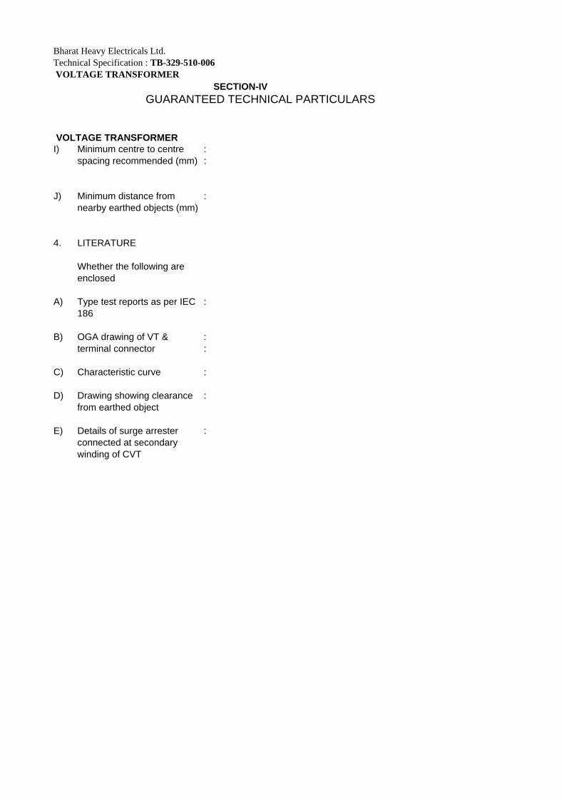
I) Minimum centre to centre :spacing recommended (mm) :
J) Minimum distance from nearby earthed objects (mm)
:
4. LITERATURE
Whether the following are enclosed
A) Type test reports as per IEC 186
:
B) OGA drawing of VT & :terminal connector :
C) Characteristic curve :
D) Drawing showing clearance :from earthed object
E) Details of surge arrester :connected at secondarywinding of CVT

SECTION 5 CHECK LIST FOR INFORMATION TO BE FURNISHED WITH OFFER
RETURN THIS CHECKLIST AS PART OF THE OFFER DULY SIGNED The offer may not be considered if the following information and this Checklist are not enclosed with the Offer. BHEL ENQUIRY. NO: BIDDER:OFFER REFERENCE: A) S.No
Parameters Data Yes / No Remarks
1. Applicable Standard IEC: 60044-2, IS-3156 2. Type Outdoor 3.1 Earthing Conditions Solidly Earthed 3.2 Rated Frequency 50 Hz 3.3 Nominal System
Voltage
33kV
3.4 Highest System Voltage 36kV 3.5 Rated Voltage 33kV/√3kV 3.6 Rated Secondary
Voltage 110/√3 kV
3.6 Rated short time withstand current for 1 sec
12.5 kA for 1 sec.
3.8 Basic Insulation Levels
Altitude correction factor considered
4 The VT Winding Parameters
As per Tables given in Clause 1.2 c of Section I
5 VT supplied Suitable for operation in the Climatic and High Altitude conditions.
Suitable for Climatic and Meteorological Data Specified in Section III
7 Oil filling & Drain Plug and Oil Sight glass
Provided
8 Max. Temperature rise over design ambient temperature
As per IEC 60044-2 & IS 3156
9 External Surface If Steel
Hot Dip Galvanized
10 Rated Voltage Factor 1.2 continuous , 1.5 – 30sec

B) TYPE TESTS i)Whether type test reports of the tests as per relevant IS-3156 and IEC 60044 conducted earlier on identical or similar material being offered are available(test reports are of the test conducted not earlier than 5 (five) years prior to the date of bid opening, 22/01/09). (YES ) ii) If type test reports are not acceptable to BHEL/Customer then above tests shall be conducted by the bidder free of cost. (YES ) Date: Signature of the authorized representative of Bidder
Company Seal