222 1959 proceedings of the western joint computer ... · 222 1959 proceedings of the western joint...
TRANSCRIPT

222 1959 PROCEEDINGS OF THE WESTERN JOINT COMPUTER CONFERENCE
IBM 7070 Data Processing System J. SVIGALSt
I N 1953, International Business Machines Corporation (IBM) introduced its first production model of a large-scale computer-the IBM 701 Data
Processing Machine. Since that time, the company has engineered and delivered a number of major data processing systems, each designed to meet certain business and scientific requirements.
These systems have included the 305 Ramac, 650 Basic, 650 Tape, 650 Ramac, 702, 704, 705, 705 III, and 709. In addition to these comp'uter systems, the completely transistorized 608 Calculatochas been in productive operation since 1957.
Each of these systems has extended and refined the growing body of practical knowledge of both the versatility and limitations of data processing equipment. The result has been an increase in the total productive time of the machine installations and more efficient use of these machine hours.
More important, the application of these systems to actual working problems has produced thousands of specially trained personnel in the business world as well as within IBM itself.
The new IBM 7070 Data Processing System is a product of the ideas and expressed needs of this experienced group. It is designed to serve as a partner of the man-machine-methods team of modern business.
The purpose of this paper is to describe the general organization of the IBM 7070. This description will include a discussion of the special features of the system and its physical and electrical characteristics.
GENERAL ORGANIZATION
The IBM 7070 Data Processing System combines advanced engineering design, based on high-speed, solidstate components, with an equally modern machine organization. The system is capable of efficient solution of both commercial and scientific applications. The IBM 7070 Data Processing System spans a wide range of capacities and features. These include punch card, magnetic tape, and magnetic tape/Ramac configurations.
The punch card IBM 7070 system consists of the central computer, one to three punch card readers, and one to three card punches or printers. The card readers operate at a speed of 500 cards a minute; the card punches operate at a speed of 250 cards a minute; and the on-line printers operate at a speed of 150 lines per minute. In the card system configuration, all card input and output devices can operate completely simultaneously with each other and with internal computation.
To achieve a tape system configuration of the IBM 7070 Data Processing System, two tape channels are
t Regional System Dept., IBM Corp., Los Angeles, Calif.
added to the computer configuration. Each tape channel is capable of operation simultaneously with the second tape channel and internal computer operation. Each tape channel may have from one to six magnetic tape units connected. These may be any combination of regular-speed (41,667 characters per second) or high-speed (62,500 characters per second) magnetic tape units. This allows for a total of 12 magnetic tape units, any two of which will operate simultaneously with computation.
A tape Ramac IBM 7070 configuration is obtained by the addition of one to four Ramac file units to the system. The Ramac units are interconnected so that they may be operated through either tape channel. This allows completely simultaneous operation of two Ramac read and/or write operation~ in a manner equivalent to that of the magnetic tape units. Each Ramac file provides three access arms. Experience with the IBM 650 Ramac systems indicates that access to these files can be achieved effectively in zero time. This is accomplished by seeking ahead for the next record while a previous record is processed.
Fig. 1-The IBM 7070 Data Processing System.
A typical IBM 7070 system is shown in Fig. 1. Included are the following units:
Console: This is a separate unit which includes the console typewriter and a small operator's panel. The console unit is designed to simplify and expedite the operator's task and to insure maximum productive machine time. The typewriter is the principal operator's tool. It replaces many of the indicator lights and control switches of previous data-processing machines. Operator error is minimized by the computer's ability to audit opera tor commands through a stored program and by a printed record of all data entered and emitted through the console typewriter.
Magnetic Tape Units: The magnetic tape units are seen to the right, rear of the picture. Two types of units are available. The 729 II reads or writes tapes at a !"ate of 41,667 characters per second. The Model IV reads ,or writes tapes at a rate of 62,500 characters per second.
Card Reader: Immediately in front of and to the left of the magnetic tape units is a card reader. This unit
From the collection of the Computer History Museum (www.computerhistory.org)
Svigals: IBM 7070 Data Processing System 223
operates at a rate of 500 cards per minute with format control by means of a control panel mounted on the reader. Data from a full 80-column punched card may be transferred into the computer simultaneously with internal computer operations. The card reader is equipped with a front attended tray feeding hopper and stacker. As many as three card readers can be utilized for card input. Selected cards may be offset in the stacker.
Card Punch: To the right of the card reader is the card punch. This unit operates at a punching speed of 250 cards per minute with format control by control panel wiring. Front attended hopper and stacker are used. Selected cards may be offset in the stacker. As many as three card punches can be utilized for card output.
Printer: The printer is located to the right front of the picture. This unit operates at a speed of 150 lines per minute with format control provided by the control panel. The printed line output consists of a span of 120 characters spaced ten to the inch.
Central Processing Unit: This unit is seen to the left rear. It contains most of the system electronics and consists of the following elements:
1) Arithmetic registers and core memory, 2) Indexing hardware, 3) Space for optional floating decimal arithmetic
(with automatic double precision operation), 4) Magnetic core memory of five or ten thousand
words, 5) Two data channels, code translators, data registers
and controls for magnetic tape and Ramac storage units,
6) Buffers and controls for card input, card output, and the printers.
Disk Storage Units: To the left of the picture are the disk storage units. These units consist of a stack of large disks which magnetically hold up to 12,000,000 digits each. Information is read from and written onto these disks by an access mechanism containing a magnetic recording head. This mechanism moves rapidly to any disk in the file. Three access mechanisms for each storage unit are provided to minimize access time by overlapping the "seek" operation. Up to four disk storage units can be utilized by the 7070 system, providing a total storage capacity of up to 48,000,000 digits of rapid, random access memory. These units are attached to the system by the same two channels that connect the magnetic tape units to the system. Each of these channels is linked to a disk storage unit by program control, and allows any combination of simultaneous read/write/ compute.
Manual Inquiry Station: The manual inquiry stations are shown immediately in front of the Ramac disk storage units. These units permit fast interrogation of data stored in the computer core storage, in the disk storage unit, or on magnetic tape. The station consists of a
5 I ~ 01 G N
• :::»
a > .0: CD
D
'i E u • D
Bit Code
o 1 236
1 • • 0 o 0 2 • o • o 0 3 • o 0 • 0 4 0 • 0 • 0 5 0 o • I 0 6 I o 0 o I 7 0 I 0 o • 8 0 o • o • 9 0 o 0 I I o 0 I • o 0
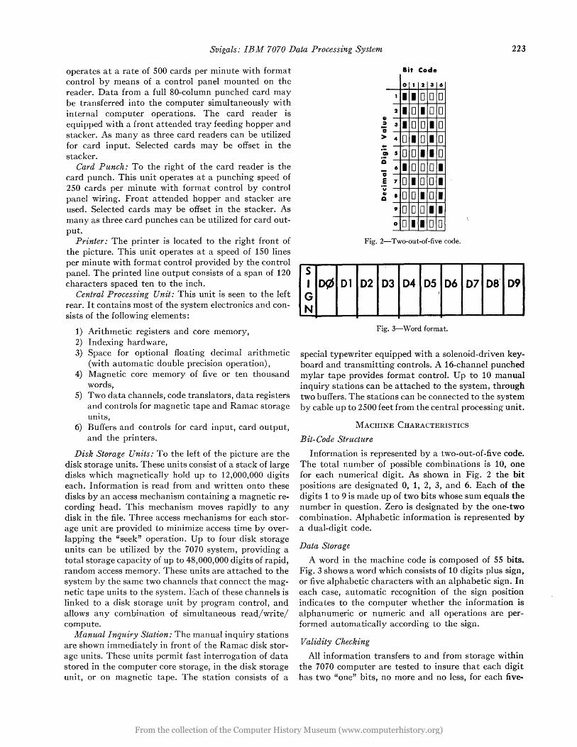
Fig. 2-Two-out-of-five code.
02 03 04 05 06 ,
Fig. 3-Word format.
07 OS' 09
special typewriter equipped with a solenoid-driven keyboard and transmitting controls. A 16-channel punched mylar tape provides format control. Up to 10 manual inquiry stations can be attached to the system, through two buffers. The stations can be connected to the system by cable up to 2500 feet from the central processing unit.
MACHINE CHARACTERISTICS
Bit-Code Structure
Information is represented by a two-out-of-five code. The total number of possible combinations is 10, one for each numerical digit. As shown in Fig. 2 the bit positions are designated 0, 1, 2, 3, and 6. Each of the digits 1 to 9 is made up of two bits whose sum equals the number in question. Zero is designated by the one-two combination. Alphabetic information is represented by a dual-digit code.
Data Storage
A word in the machine code is composed of 55 bits. Fig. 3 shows a word which consists of 10 digits plus sign, or five alphabetic characters with an alphabetic sign. In each case, automatic recognition of the sign position indicates to the computer whether the information is alphanumeric or numeric and all operations are performed automatically according to the sign.
Validity Checking
All information transfers to and from storage within the 7070 computer are tested to insure that each digit has two "one" bits, no more and no less, for each five-
From the collection of the Computer History Museum (www.computerhistory.org)

224 1959 PROCEEDINGS OF THE WESTERN JOINT COMPUTER CONFERENCE
bit position. Because the checking is for an exact number of "one" bits for every digit, this type of coding structure affords a complete and consistent self-checking of data flow.
Data Transmission
An important feature of the 7070 is parallel transmission of data to and from core storage. An entire word, including sign, is moved all at once. A channel for parallel bit transmission consists of SS lines, one for each bit in each of the 10 digits and the sign position. This enables a word in core storage to be moved in 6 fJ.sec to or from core storage. Data are transmitted between the core registers within the computer at a 4-fJ.sec rate. All information is transmitted in parallel with the exception of data transmitted to and from the magnetic tape units. Parallel transmission is represented by the parallel lines in Fig. 4. The accumulators all have serial paths connecting them to the core adder. There also is a serial data path to and from the input/output synchronizers.
A rithmetic Operations
The arithmetic unit of the IBM 7070 contains three' accumulators, each with a capacity of 10 digits and sign.
MAGNETIC CORE STORAGE 0000 TO 9989
In addition to the accumulators, the auxiliary register and the arithmetic register are each capable of contain- 1 ing ten digits and sign. The interconnection of these uni ts is shown in Fig. 4.
Addition
An amount to be added to an accumulator is brought to the arithmetic register. The number in the accumula tor is sent to the auxiliary register. The con ten t of these two registers is added, one digit at a time, and as the result is developed by the adder, it is brought to the arithmetic register. At the conclusion of the operation, the result is sent from the arithmetic register to the designated accumulator.
Arithmetic Timing
The duration of an arithmetic operation is determined by the size, in digits, of the factors. In an add instruction, for example, it is determined by the size of the field or by the significant digits in the accumulator, whichever is greater. Arithmetic operations take only the amount of time needed to perform the actual computation; there is no time wasted in accumulating a full tendigit number for each arithmetic operation. The addition times for fixed point operation are shown in Table 1. These figures include access time for the instruction and an operand.
TABLE I
Length of Operand
1, 2, or 3 digits 4, 5, or 6 digits 7, 8, 9, or 10 digits
Execution Time
48 p'sec 60 p.sec 72 p'sec
Fig. 4-IBM 7070 data-flow schematic.
I nstruction Format
Each instruction in the program consists of 10 digits and sign. The digit positions are numbered 0 through 9 (left to right) as shown in Fig. S. For most operations these digits are utilized as follows:
Sign and positions 0-1: Positions 2-3: Positions 4-5: Positions 6-9:
operation code indexing word control digits address
Operation Code: The sign and first two digit positions provide for a maximum of 200 different operation codes of which 120 are currently used. In addition, some of the operation codes have multiple functions. These are accomplished through different values which are placed in digit positions four and five to further define the operation. For example, in a card operation, position four specifies a particular input or output unit. Position five defines the specific card operation such as read, punch, or print.
From the collection of the Computer History Museum (www.computerhistory.org)

Svigals: IBM 7070 Data Processing System 225
INDEX FIELD WORD CONTROL
~~~( __ A __ \
OP o
s , D(Zj 01 G N
+ ¢¢-99 -
02 03
¢¢XX
04
S T A R T
05 06 07 08 09
S DATA ADDRESS T BRANCH ADORE 0 DATA VALUE p
Fig. 5-Instruction format.
SS
Index Word: Positions 2 and 3 of the instruction specify the indexing word to be used. There are 99 index words in the magnetic core storage, each of which contains a 10-digit number with sign. They are stored in memory locations 0001-0099. The indexing word portion of a program step determines which of these 99 index registers will be applied; 00 means no indexing.
Control: In all of the arithmetic instructions, any portion of a word can be processed as easily as the entire word. Positions 4 and 5 of an instruction determine the part of the word that will be used. The digit in position 4 denotes the left end of the field. The digit in position 5 specifies the right end of the field. This is called "field definition." The field definition feature means that several fields with like signs can be stored in a single word with no inconvenience to the programmer in processing an individual field. It should be noted that in all arithmetic operations using field definition, information extracted from a word is shifted automatically to the right when placed into the designated accumulator. In storage operations, a number of digits equal to that specified by the field definition digits is extracted automatically from the right-hand portion of the accumulator, shifted left to the designated location of the word, and then inserted in the word without disturbing the remaining digits. Field definition operations occur without any additional execution time.
Address: The address portion of an instruction, positions 6-9, may refer to the storage location of the data or the location of the next instruction.
Indexing: As stated previously, memory locations 0001-0099 also may be used as index registers. When a word is used as an index register, the digits have the following value:
Sign position: This specifies whether the actual value of the indexing portion shall be added to or subtracted from an address during an index operation.
Digits 0-1 : Not used. Digits 2, 3, 4, 5: This is the indexing portion of the
index word. Together with the sign of the index
Coding
Automatic validity check from tape on writing operation?
Character density
Passing speed
Character rate (maximum)
COMPARISON CHART 729 TAPE UNITS
Model II
Even number out of 7 (C, B, A, 8, 4, 2, 1)
Yes
200-555 characters per inch
75 inches per second
41,667 alphanumerical characters per second
Model IV
Even number out of 7 (C, B, A, 8, 4, 2, 1)
Yes
200-555 characters per inch
approx.112.5 inches per second'
approx. 62,500 alphanumerical characters per second
Fig. 6-Magnetic tape characteristics.
word, this portion is added to the data address of the instruction. All instructions are indexable.
Digits 6, 7, 8, 9: This is the fixed portion of the index word and may be used by the programmer to store constants, decrements, increments, or limits.
Magnetic Tape Characteristics: The IBM 7070 DataProcessing System provides two types of magnetic tape units. These are the IBM 727 Model II or the 729 Model IV. Data from magnetic tape to the system are read into magnetic-core storage, and a record is written on tape from the core unit. Any group of locations in core storage can be used for these purposes. The tape control unit provides two channels, each connecting as many as six tape units with the main system. The total of 12 magnetic tape units can be used in any combination. The comparative characteristics of the two tape unit models are shown in Fig. 6. The primary difference between them is the greater density of bit storage and passing speed of Model IV. Both units provide high-speed rewind at a maximum speed of 500 inches per second.
Successive records on tape are separated by a blank space called the interrecord gap. Every tape-read instruction causes an entire record to be read: the reading is stopped by the interrecord gap. The size of a tape record has no limitation except the capacity of core storage used in transferring the information to or from the tape. When reading from the tape, even this restriction is not rigid if data from only a portion of the tape record are needed. The program defines the number of words and locations that can be read in to core storage. Any information from the tape in excess of that amount is not accepted by the machine.
The coding structure used on magnetic tape is a scvenbit alphanumerical code. This code is identical to that used by other IBM data-processing tape systems. Every character must have an even number of bits, and all are tested for this in every tape read or write operation. In addition, there is a horizontal check of each record. As the record is written on tape, a horizontal check char-
From the collection of the Computer History Museum (www.computerhistory.org)

226 1959 PROCEEDINGS OF THE WESTERN JOINT COMPUTER CONFERENCE
acter is created to make the number of bits even in each of the seven channels. The check character itself must have an even number of "one" bits to make the over-all total of bits even.
The IBM 729 tape units have an additional checking feature on tape-writing operations. The reading head reads the tape just after it is written. This function is illustrated in Fig. 7. This check is performed automatically and provides immediate verification of the actual tape record.
NEW MACHINE CHARACTERISTICS
Record Definition Words
An important new concept introduced by the IBM 7070 Data-Processing System is that of record definition words. These words define the first and last addresses of a block of data stored in core storage. One of these words is placed in storage for each block. The words may be used singularly or in tables of record definition words, as shown in Fig. 8. In each case, the last word in the table is signified by a minus sign. Record definition words are used for all data movement of more than one word at a time. This includes disk storage read and write, core-to-core block transmissions, movement of input data from the input buffers and output data to the output buffers, inquiry and reply information, and others.
Scatter Read/Gather Write
A powerful programming tool in 7070 operations is scatter read/gather write. This is illustrated in Fig. 9. A single record read from tape can be divided into as many parts as desired by the programmer. These parts are distributed to the different blocks of core storage as the tape is read. The figure shows how an inventory record is separated by field and category during the tape reading procedure. This operation is controlled by the table of record definition words shown in Fig. 8. This feature applies to writing on tape as well as reading from it. It enables the program to gather data from various blocks and automatically assemble them into one tape record.
Record Afark Words
Words containing the record mark character give an additional flexibility to the scatter read/gather write feature. Detection of the record mark word automatically denotes the end of a block in a scatter read/gather write operation. In scatter read, a tape record will not con tin ue to fill the storage block if a record mark word is read into the storage area. Instead, it goes to the next block and begins to fill it with the characters immediately following the record mark word. In tape writing, a record mark word. in core storage will signal the system to stop moving data from that block and start sending
Fig. 7-Two-gap read-write head.
SOl 2345 6789 I : I I
LOCATION~: I I STARTING: ENDING en I ! I ADDRESS I ADDRESS
i I I I
I I I :
3211 +:0: 0: 237 1 12380 3212 +:0:0:0021'0021 3213 +:0:0; 41 75 '41 94 3214 +1010: 1 71 6 1 720 3215 +:0:013617 3621 3216 +:0:0: 0104 011 0
I I 3~17 +10.0: 440 1 4425
I I
3218 +:0:0: 2803 2803 3219 +:0;0: 3913 3919 3220 +:0:0: 0305 0307 3221 -!O:O: 4853.4877 Fig. 8-Record definition words.
from the next block. Tape read or write instruction determines whether the record mark word will be operative. If not, a record mark word is treated as a normal alphabetic word.
Zero Elimination
When a numeric word in, storage is written on tape, as many as five high-order zeros can be automatically eliminated. The sign of a word is combined with its unit position digit. When the tape is read, the presence of a sign combined with a digit indicates the unit position of a word. The core storage word will be filled automatically with zeros in the high-order positions to replace those eliminated during the write operation. The functions of record mark word and zero elimination are completely automatic and require no additional execution time other than the time normally required to read and write magnetic tape at full tape rate. These functions result in a variable word and variable record size on magnetic tape.
From the collection of the Computer History Museum (www.computerhistory.org)

Svigals: IBM 7070 Data Processing System
-+/ laG IJ....--------------- INVENTORY RECORD---------------....-I.I laG I*-
~ UNIT PRICES ::! SALES THIS PERIOD
ITEM UNIT UNIT :! ON MIN.
UNITS 1 DESCRIPTION UNIT
ZONE 1 1 ZONE 21 ZONE 31~ i HAND NO. WGT COST BAL. INV. COST
L~~~~ I???~ c· . . . . . . . . • • TAPE CHANNEL
II II I II I II - RE·ORD. MIN. t=
UNIT INV.
COST
UNIT
~ DISC. el.
1= ITEM
1= NO.
1= UNIT WGT.
MAGNETIC CORE ON STORAGE HAND
BAL.
1= 1= 1=
UNIT 1= PRICES SALES ~
THIS 1= PERIOD 1= DESe.
1= l=-I:: 1=
II III mm TTTTTn
Fig. 9-Scatter read/gather write example.
CHANNEL CONTROL
The magnetic tape system of the 7070 has two channels, each connecting as many as six tape units with magnetic core storage. The channels also connect to as many as four disk storage units. These disk units can be programmed to use either channel, whereas a tape unit can use only the one connecting it to the central processing area.
The primary purpose of the additional channel is to allow the IBM 7070 to perform two operations simultaneously-reading two tapes, writing two tapes, or reading one and writing one. Each control channel performs one of the two tape read/write operations; while these simultaneous operations are taking place the program can continue. The function of the tape channel is shown diagrammatically in Fig. 10.
MAGNETlC·CORE STORAGE
1 PRICE
I
moved from storage to Record Definition Regis,er
Information is moved between core storage and disk or tape storage by the transmission registers. The purpose of the transmission registers is to change the type of transmission from serial to parallel, or vice versa, and to synchronize the speed of the tape or disk with the speed of magnetic core storage. Data must move to and from tape and disk storage serially, but they are always Fig. 10-Tape/disk channel control schematic.
227
From the collection of the Computer History Museum (www.computerhistory.org)

228 1959 PROCEEDINGS OF THE WESTERN JOINT COMPUTER CONFERENCE
sent to and from core storage in parallel. In reading tape or disk storage record, the characters are read serially into transmission register A until the ten-digit positions and sign position are filled. At this point they are sent in parallel to transmission register B. Register A then starts to fill up serially again with the next characters on the tape or disk record. The contents of register Bare sent in parallel to the magnetic core storage location specified. In tape or disk storage write operations, data go in parallel to transmission register B, then in parallel to transmission register A, and serially to a tape or disk storage unit.
The storage locations are controlled by the record definition register, one of which is used for each tape channel. The starting (or working) and stop addresses in the registers are obtained from a table of record definition words stored in the memory. As a word is read from tape, the content of the working address is increased by one and compared with the stop address. After each word is read from tape, these addresses are compared. If they are unequal, the working address is increased by one and the next word is moved from tape to the new storage location specified.
This process continues until the working and stop addresses become equal, or until a record mark word is read. At that point, the last word is transferred, and the sign position in the record definition register is tested. If it is plus, the record definition word address register is increased by one, and a new record definition word is brought in from storage to designate a new block of words. When the sign of the record definition register is minus, this means the last record definition word in the operation has been reached and the operation is completed.
The operations described here are accomplished automatically within the record read or write time. The combination of zero elimination, record definition words, and record mark words provide a completely automatic method of obtaining variable word size, record size, and block size on magnetic tape.
Segment Forward or Backward Space per Count
These are new commands designed to allow automatic spacing over a series of tape records. The spacing operation can be performed with the tape moving in a forward or reverse direction. The tape is moved at full speed until one or several segment marks are sensed. The number of segments skipped is defined by a record definition word. The segment marks are recorded on the tape under program control and can be used for any type of demarcation required, such as a fixed number of tape records or a change in the file sequence con trol.
Table LO(Jk- Up Operations
There are three types provided in the IBM 7070. They are 1) equal or high, 2) equal, and 3) lowest. In equal or high, a sequential table is searched for the first entry that is equal to, or higher than, the search criteria.
Table look-up equal searches a random table for an entry equal to the search criteria. Table look-up lowest searches a random table for the entry with the lowest search criteria.
Floating Decimal Arithmetic
An optional computing feature of the IBM 7070 is the use of floating decimal operations. This includes automatic floating point double precision operations which provide eight high-order and eight low-o~der Mantissa digits, each with its correct, two-digit characteristic.
A utomatic Priority Processing
This new programming feature makes it possible to process more than one program during the same period. This procedure eliminates time lost in waiting for input/ output operation to be completed, since one program or another is constantly functioning. One of the programs, called the main routine, has a comparatively large number of program steps. The others, called the priority routines, have relatively few instructions, but involve almost continuous use of card reader, card punch, printer, tape unit, or disk file.
The main routine functions normally, while the tape, disk storage, or input/output unit in the priority routine is operating. These operations may include reading a card, punching. a card, reading tape, writing tape, seeking a disk file record, reading a record file, or writing a file record. When anyone of the preceding operations is completed, the main routine is signalled automatically. The priority routine carries out its program, stops its input/output or storage unit, and releases priority. The main routine then takes up exactly where it left off. It is possible to have more than one tape, disk storage, or input/output unit operating on a priority basis during the main routine. However, only the main routine can be signalled for priority; it is not possible to do this to a priority routine. If a second priority is ready while the first one is in progress, it will wait until the first one is completed. The main routine is resumed only when there are no priority routines waiting.
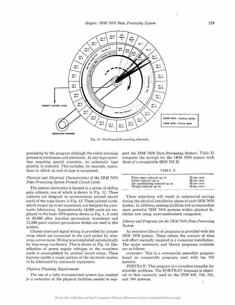
Priori ty is determined by the setting of the stacking latches, shown diagrammatically in Fig. 11. There are stacking latches for the card input/output units, one for each tape unit, and one for each of the three read/ wri te heads in each disk file. Each program step in the main routine tests any or all of these latches to see if the priority routine is ready. These tests are made without any delay in the program steps of the main routine.
There are four types of priority: card, tape, disk file, and inquiry. Card priority is caused by the completion of a card read, card punch, or print operation. A tape priority routine is initiated by the completion of a tape read or write operation, and disk file priority is started at the conclusion of a disk file read, write, or seek. A manual inquiry automatically initiates an inquiry priority routine. In all cases, the program may test, set, or reset any.latch. This allows complete control of priority
From the collection of the Computer History Museum (www.computerhistory.org)
Svigals: IBM 7070 Data Processing System 229
PRIORITY WAITING LATCH
OUTER RING - Stacking Latches
INNER RING - Priority Mask
SEQUENCING SCANNER
Fig. l1-Stacking-Iatch scanning schematic.
processing by the program although the entire scanning process is continuous and automatic. In any tape operation requiring special attention, an automatic tape priority is initiated. This includes, for example, operations in which an end-of-tape is recognized.
Physical and Electrical Characteristics of the IBM 7070 Data-Processing System Printed Circuit Cards
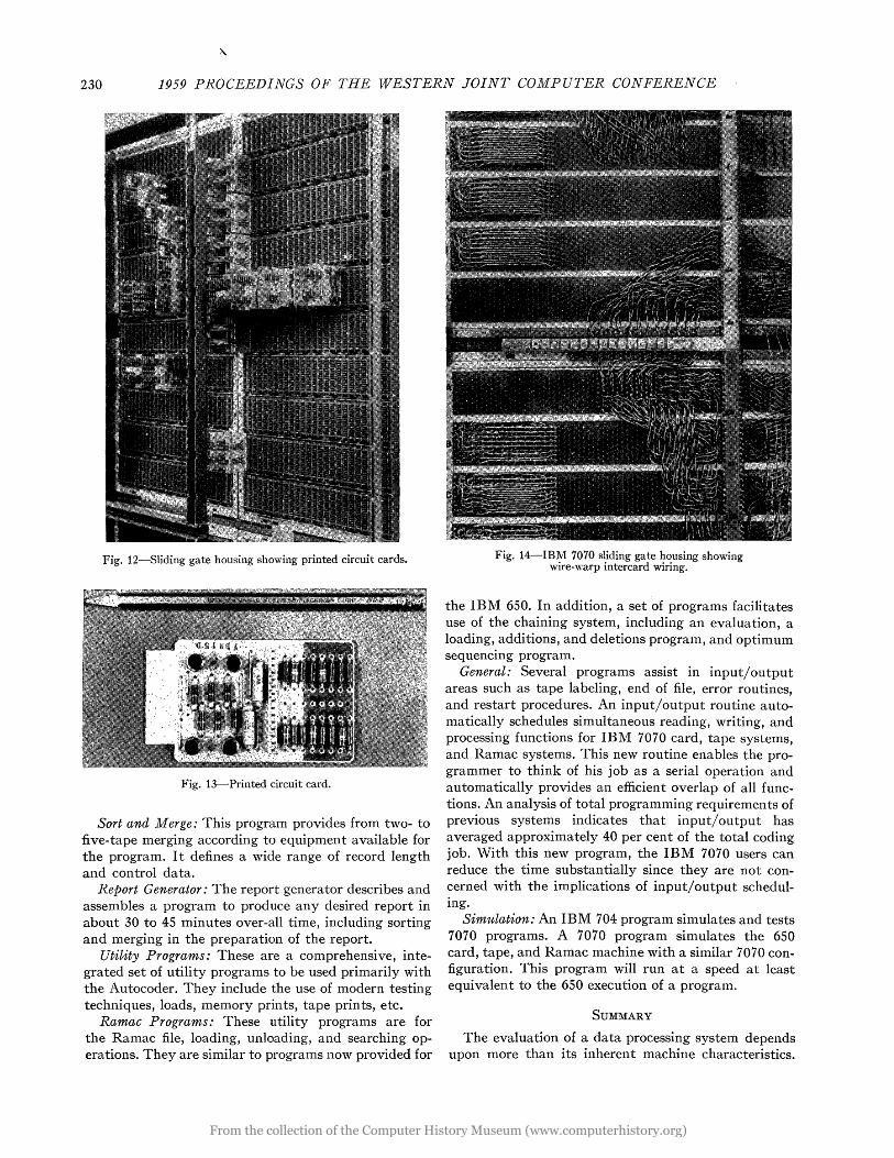
The system electronics is housed in a group of sliding gate cabinets, one of which is shown in Fig. 12. These cabinets are designed to accommodate printed circuit cards of the type shown in Fig. 13. These printed cards, which mount up to six transistors, are designed for automatic fabrication. Approximately 14,000 cards are employed in the basic 7070 system shown in Fig. 1. A total of 30,000 alloy junction germanium transistors and 22,000 point contact germanium diodes are used in this system.
Chassis in tercard signal wiring is provided by j urn per wires which are connected to the card socket by wirewrap connections. Wiring is accomplished automatically by wire-wrap machinery. This is shown in Fig. 14. Distribution of power supply voltages to the transistor cards is accomplished by printed circuit strips. These features enable a major portion of the electronic system to be fabricated by automatic equipment.
Physical Planning Requirements
The use of a fully transistorized system has resulted in a reduction of the physical facilities needed to sup-
port the IBM 7070 Data-Processing System. Table II compares the savings for the' IBM 7070 system wit~ those of a comparable IBM 70~ II.
TABLE II
Floor space reduced up to Power reduced up to Air conditioning reduced up to Weight reduced up to
50 per cent 58 per cent 58 per cent 50 per cent
These reductions will result in substantial savings during the physical installation phase of each IBM 7070 system. In addition, existing facilities will accommodate more powerful IBM 7070 systems within physical facilities now using nontransistorized computers.,
Library and Programs for the IBM 7070 Data-Processing System
An extensive library of programs is provided with the IBM 7070 system. These reduce the amount of time and effort normally required in a computer installation. The major automatic and library programs available are as follows: .
Autocoder: This is a commercial assembler program based on comparable programs used with the 705 systems.
FORTRAN: This program is a complete compiler for scientific problems. The FORTRAN language is identical to that currently used on the IBM 650, 704, 705, and 709 systems.
From the collection of the Computer History Museum (www.computerhistory.org)
230 1959 PROCEEDINGS OF THE WESTERN JOINT COMPUTER CONFERENCE
Fig. 12-S1iding gate housing showing printed circuit cards.
Fig. 13-Printed circuit card.
Sort and Merge: This program provides from two- to five-tape merging according to equipment available for the program. I t defines a wide range of record length and control data.
Report Generator: The report generator describes and assembles a program to produce any desired report in about 30 to 45 minutes over-all time, including sorting and merging in the preparation of the report.
Utility Programs: These are a comprehensive, integrated set of utility programs to be used primarily with the Autocoder. They include the use of modern testing techniques, loads, memory prints, tape prints, etc.
Ramac Programs: These utility programs are for the Ramac file, loading, unloading, and searching operations. They are similar to programs now provided for
Fig. 14-IBM 7070 sliding gate housing showing wire-warp intercard wiring.
the IBM 650. In addition, a set of programs facilitates use of the chaining system, including an evaluation, a loading, additions, and deletions program, and optimum sequencing program.
General: Several programs assist in input/output areas such as tape labeling, end of file, error routines, and restart procedures. An input/output routine automatically schedules simultaneous reading, writing, and processing functions for IBM 7070 card, tape systems, and Ramac systems. This new routine enables the programmer to think of his job as a serial operation and automatically provides an efficient overlap of all functions. An analysis of total programming requirements of previous systems indicates that input/ output has averaged approximately 40 per cent of the total coding job. With this new program, the IBM 7070 users can reduce the time substantially since they are not concerned with the implications of input/output scheduling.
Simulation: An IBM 704 program simulates and tests 7070 programs. A 7070 program simulates the 650 card, tape, and Ramac machine with a similar 7070 configuration. This program will run at a speed at least equivalent to the 650 execution of a program.
SUMMARY
The evaluation of a data processing system depends upon more than its inherent machine characteristics.
From the collection of the Computer History Museum (www.computerhistory.org)

Fleming: Organizational A pproach to Integrated Data Processing 231
It includes the procedures, methods, and programs provided with the system and the manufacturers' support needed during the pre-installation, installation, and post-installation phases. All of these necessary and important features are provided with the IBM 7070 Data Processing System.
Specifically, they are:
Balance System: The high speed of computing and internal flow of data are balanced by high-speed tape units, rapid access storage in the disk files, and highspeed card readers and punches.
Maximum Utilization: Automatic priority processing allows efficient time-sharing and multiprogramming abilities for input, output, tape, disk file, and inquiry opera tions.
Building Blocks: A variety of units in varying capacities permit custom-made systems with the ability to grow as the user's needs are increased.
Application Range: The 7070 can handle a wide range of applications, including batch processing, in-line processing, and computing. It covers the area of mediumto large-scale systems.
Transistors: Solid-state components offer such advantages as high reliability and reduced requirements for floor space, electric power, and air conditioning.
Access and Use of Storage: Each word in core storage can be used for a program step, input or output. Scatter read and gather write minimizes the need for additional
steps which arrange data or assemble them for tape opera tions.
Simultaneous Operations: Transferring data to and from the system can be overlapped with computing operations.
Fully Alphabetic: A complete 80-column card can be read in or punched for any combination of numeric and alphabetic data.
Programming Logic: Field definition, 99 index wordE., single address instruction, and many other factors contribute to direct and simple programming logic.
Variable-Length Records: Full flexibility in handling grouped records of variable length on tape is provided automatically by the scatter read and gather write feature and automatic zero elimination.
Reliability: Complete checking both of input, output, internal operations, and tape and disk storage insure the ultimate in performance.
Programming Systems: Assembly programs and a number of other library routines assist in the planning and programming.
Programming Testing: Programs can be tested prior to delivery permitting full operation immediately after installa tion.
IBM Services: IBM offers training, planning and programming assistance, customer engineering, and other services. These are the vital steps necessary to insure that the man-machine-methods team is complete and will function properly.
An Organizational Approach to the Development of an Integrated Data-Processing Plan
GEORGE J. FLEMINGt
T HE dictionary defines organization in four ways. One of these definitnios is: "The way a thing's parts are arranged to work together," and this is
the one that most nearly describes the subject. The term integrated data processing has various
meanings. Although originally used to describe commonlanguage machine procedure it has gradually been extended to include all phases of the processing of data and is often used to describe the wedding of two or more data systems. For the purposes of this paper, the broader definition will be used.
The reasons for which data are processed may be categorized as follows:
t Boeing Airplane Co., Seattle, Wash.
1) Top-level management reports. 2) Middle-management reports. 3) Functional reports. 4) First-level management and operating reports.
Although these categories are a bit arbitrary, they are a useful classification for establishing the requirements of an integrated system. Each of these categories competes with the other for data and each has the following characteristics:
1) Requirement for data and supporting records. 2) Cycles on which they are produced. 3) The degree of accuracy .that needs to be main
tained. 4) Manner or method of presentation.
From the collection of the Computer History Museum (www.computerhistory.org)