2.500 desalination and water purification · 2.500 desalination and water purification ... fs mt...
TRANSCRIPT

MIT OpenCourseWarehttp://ocw.mit.edu
2.500 Desalination and Water Purification Spring 2009
For information about citing these materials or our Terms of Use, visit: http://ocw.mit.edu/terms.
© 2009, Koch Membrane Systems, Inc. All rights reserved
Koch Membrane Systems, Inc.Innovative Products for Water and
Wastewater Treatment
© 2009, Koch Membrane Systems, Inc. All rights reserved.
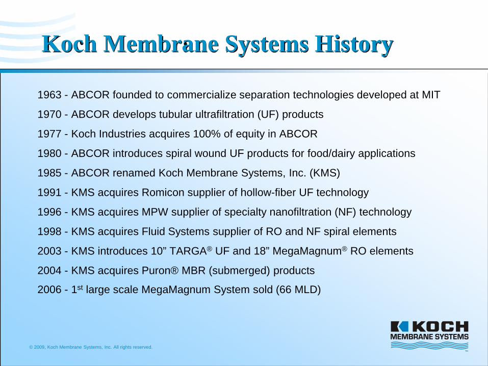
Koch Membrane Systems History
1963 - ABCOR founded to commercialize separation technologies developed at MIT
1970 - ABCOR develops tubular ultrafiltration (UF) products
1977 - Koch Industries acquires 100% of equity in ABCOR
1980 - ABCOR introduces spiral wound UF products for food/dairy applications
1985 - ABCOR renamed Koch Membrane Systems, Inc. (KMS)
1991 - KMS acquires Romicon supplier of hollow-fiber UF technology
1996 - KMS acquires MPW supplier of specialty nanofiltration (NF) technology
1998 - KMS acquires Fluid Systems supplier of RO and NF spiral elements
2003 - KMS introduces 10” TARGA® UF and 18” MegaMagnum® RO elements
2004 - KMS acquires Puron® MBR (submerged) products
2006 - 1st large scale MegaMagnum System sold (66 MLD)
© 2009, Koch Membrane Systems, Inc. All rights reserved.
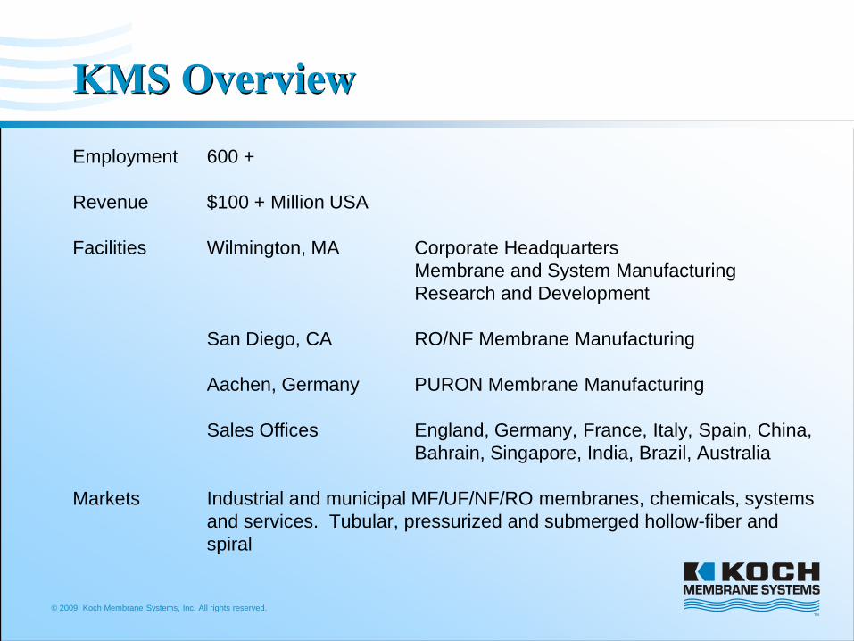
KMS OverviewEmployment 600 +
Revenue $100 + Million USA
Facilities Wilmington, MA Corporate HeadquartersMembrane and System ManufacturingResearch and Development
San Diego, CA RO/NF Membrane Manufacturing
Aachen, Germany PURON Membrane Manufacturing
Sales Offices England, Germany, France, Italy, Spain, China, Bahrain, Singapore, India, Brazil, Australia
Markets Industrial and municipal MF/UF/NF/RO membranes, chemicals, systems and services. Tubular, pressurized and submerged hollow-fiber and spiral
© 2009, Koch Membrane Systems, Inc. All rights reserved.
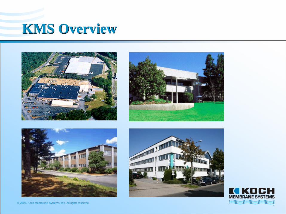
KMS Overview
© 2009, Koch Membrane Systems, Inc. All rights reserved.
KMS Business Focus
• Water and Wastewater (48%)
– Feed water and effluent treatment
– Process water recovery and reuse
• Food, Dairy and Beverage (33%)
– In-process applications for consumable products
– All products in this focus area are FDA approved
• Specialty Applications (19%)
– In-process applications for industrial processes
© 2009, Koch Membrane Systems, Inc. All rights reserved.
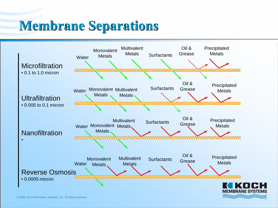
Membrane Separations
WaterMonovalent
Metals
MultivalentMetals
Oil &GreaseSurfactants
Microfiltration• 0.1 to 1.0 micron
Ultrafiltration• 0.005 to 0.1 micron
Nanofiltration•
Reverse Osmosis• 0.0005 micron
Water MonovalentMetals
MultivalentMetals
Oil &GreaseSurfactants
Water MonovalentMetals
MultivalentMetals
Oil &GreaseSurfactants
WaterMonovalent
MetalsMultivalent
Metals
Oil &GreaseSurfactants
PrecipitatedMetals
PrecipitatedMetals
PrecipitatedMetals
PrecipitatedMetals
© 2009, Koch Membrane Systems, Inc. All rights reserved.
Membrane Chemistries
• Membrane Chemistries:– Polysulfone (PSF)
– Polyethersulfone (PES)
– Polyacrylonitrile (PAN)
– Polyvinylidene fluoride (PVDF)
– Cellulose Acetate (CA)
– Polypropylene (PP)

© 2009, Koch Membrane Systems, Inc. All rights reserved.
Membrane Configurations
• Membrane Product Configurations:
– Tubular
– Spiral wound
– Hollow fiber
• Pressurized
• Submersible
© 2009, Koch Membrane Systems, Inc. All rights reserved.10
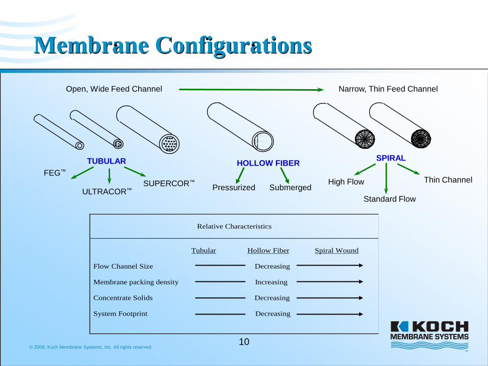
Membrane ConfigurationsOpen, Wide Feed Channel Narrow, Thin Feed Channel
FEG™
ULTRACOR™SUPERCOR™
TUBULAR
High Flow Thin Channel
SPIRAL
Standard Flow
HOLLOW FIBER
Relative Characteristics
Tubular Hollow Fiber Spiral Wound Flow Channel Size Decreasing Membrane packing density Increasing Concentrate Solids Decreasing System Footprint Decreasing
Pressurized Submerged
© 2009, Koch Membrane Systems, Inc. All rights reserved.
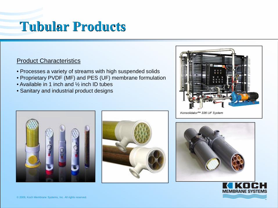
Product Characteristics
• Processes a variety of streams with high suspended solids• Proprietary PVDF (MF) and PES (UF) membrane formulation• Available in 1 inch and ½ inch ID tubes• Sanitary and industrial product designs
Tubular Products

© 2009, Koch Membrane Systems, Inc. All rights reserved.
Hollow Fibers (Pressurized)
HF-10 System
Product Characteristics
• Propriety modified PS membranes• Inside to Outside permeate flow direction• Available in 10,000 and 100,000 MWCO• Available in 35 mil (0.9 mm) and 43 mil (1.1 mm) fiber ID• Modular Designs for Future Expansions• Larger Size Cartridges reduce Capital and Operating Costs

© 2009, Koch Membrane Systems, Inc. All rights reserved.
Hollow Fiber (Vacuum)
Product Characteristics
• Proprietary PES reinforced hollow-fiber membrane• Single header design to minimize sludge buildup• Efficient air sparging for high energy efficiency
© 2009, Koch Membrane Systems, Inc. All rights reserved.
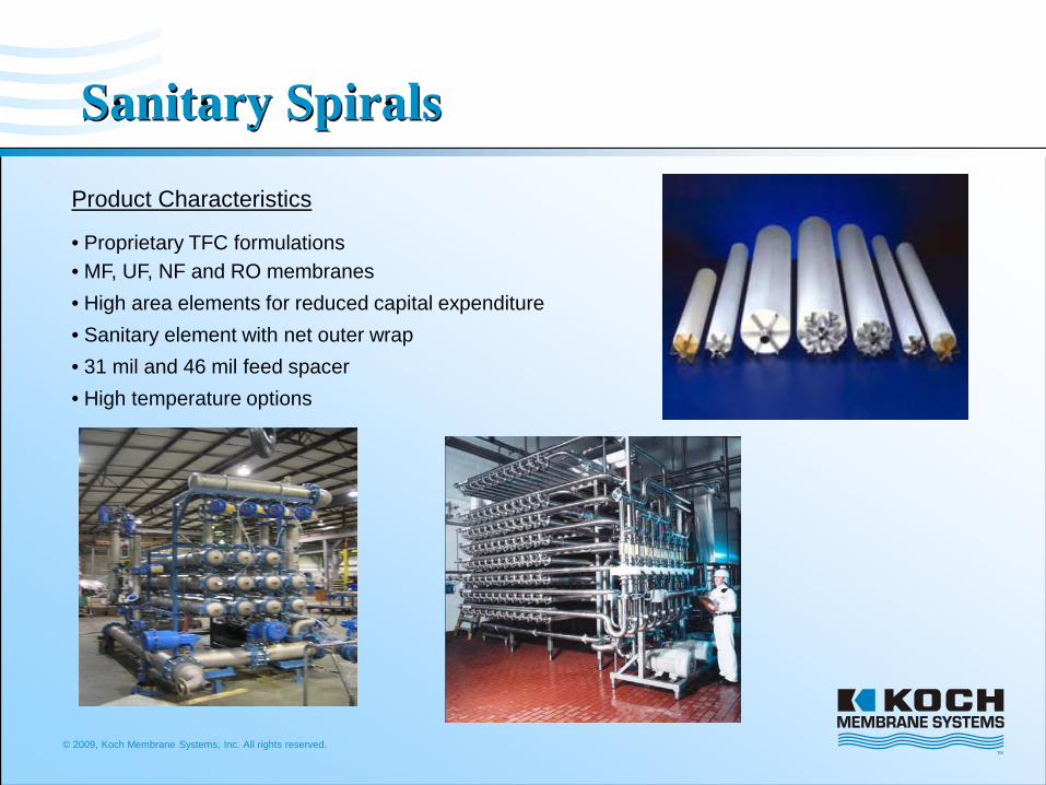
Sanitary Spirals
Product Characteristics
• Proprietary TFC formulations• MF, UF, NF and RO membranes• High area elements for reduced capital expenditure• Sanitary element with net outer wrap• 31 mil and 46 mil feed spacer• High temperature options
© 2009, Koch Membrane Systems, Inc. All rights reserved.
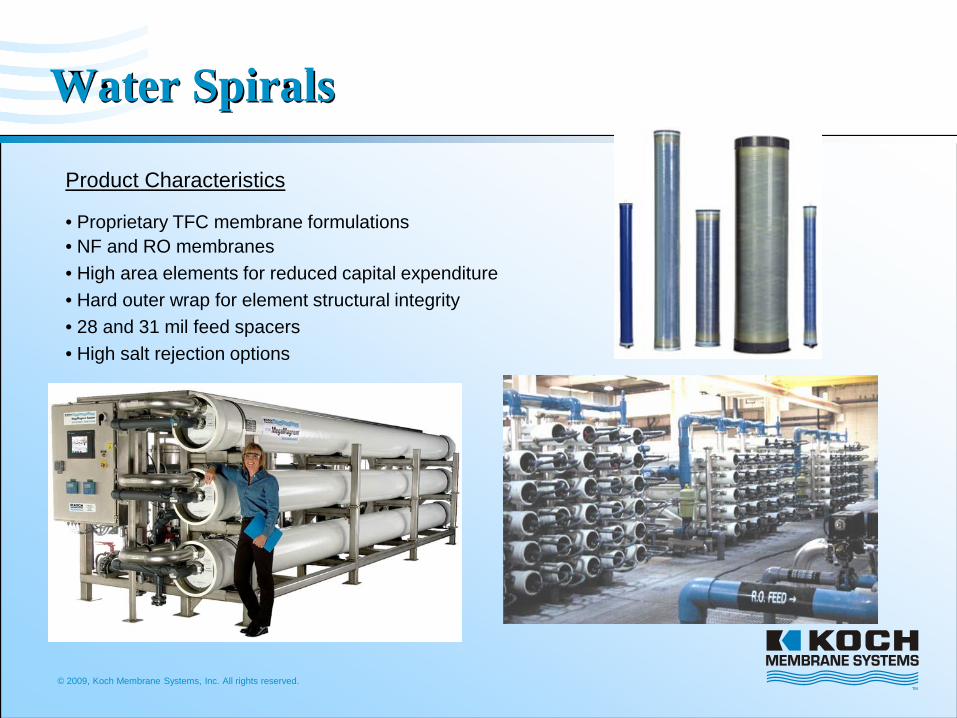
Water Spirals
Product Characteristics
• Proprietary TFC membrane formulations• NF and RO membranes• High area elements for reduced capital expenditure• Hard outer wrap for element structural integrity• 28 and 31 mil feed spacers• High salt rejection options
© 2009, Koch Membrane Systems, Inc. All rights reserved.
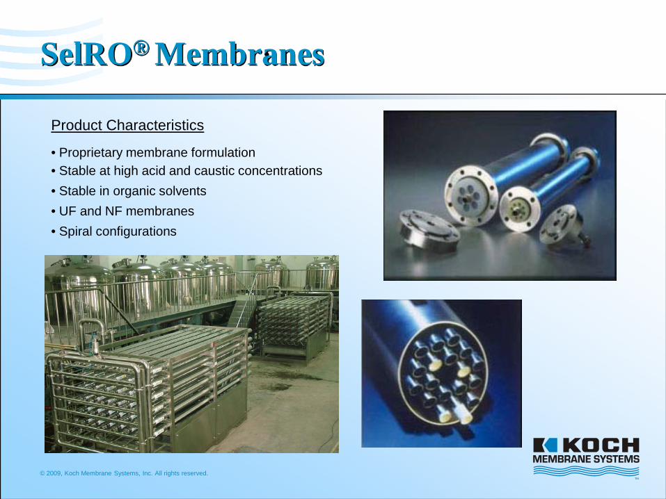
SelRO® Membranes
Product Characteristics
• Proprietary membrane formulation• Stable at high acid and caustic concentrations• Stable in organic solvents• UF and NF membranes• Spiral configurations
© 2009, Koch Membrane Systems, Inc. All rights reserved.
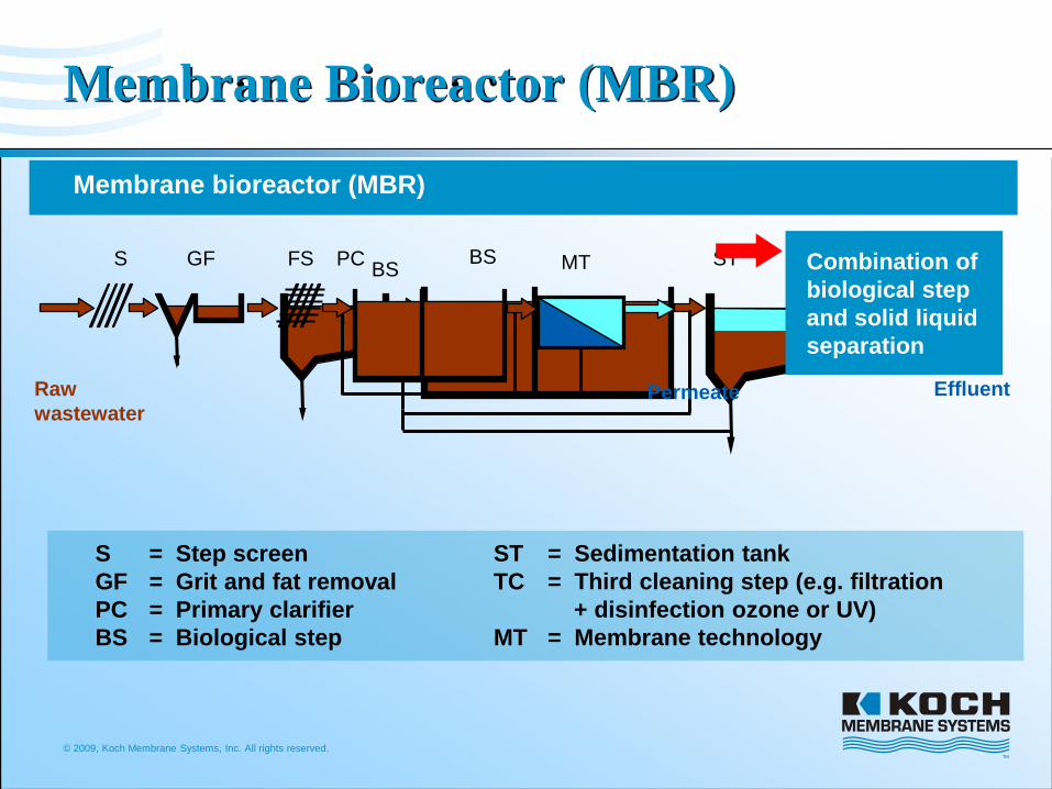
Effluent
TCPC BS STBSFS MT
Permeate
Combination of biological step and solid liquid separation
Raw wastewater
S GF
Membrane Bioreactor (MBR)
SGFPCBS
= Step screen= Grit and fat removal= Primary clarifier= Biological step
STTC
MT
= Sedimentation tank= Third cleaning step (e.g. filtration
+ disinfection ozone or UV)= Membrane technology
Membrane bioreactor (MBR)

© 2009, Koch Membrane Systems, Inc. All rights reserved.
Central air injection+
Fiber cage
Air injectionModule-element
PermeatePermeate
PURON – module row
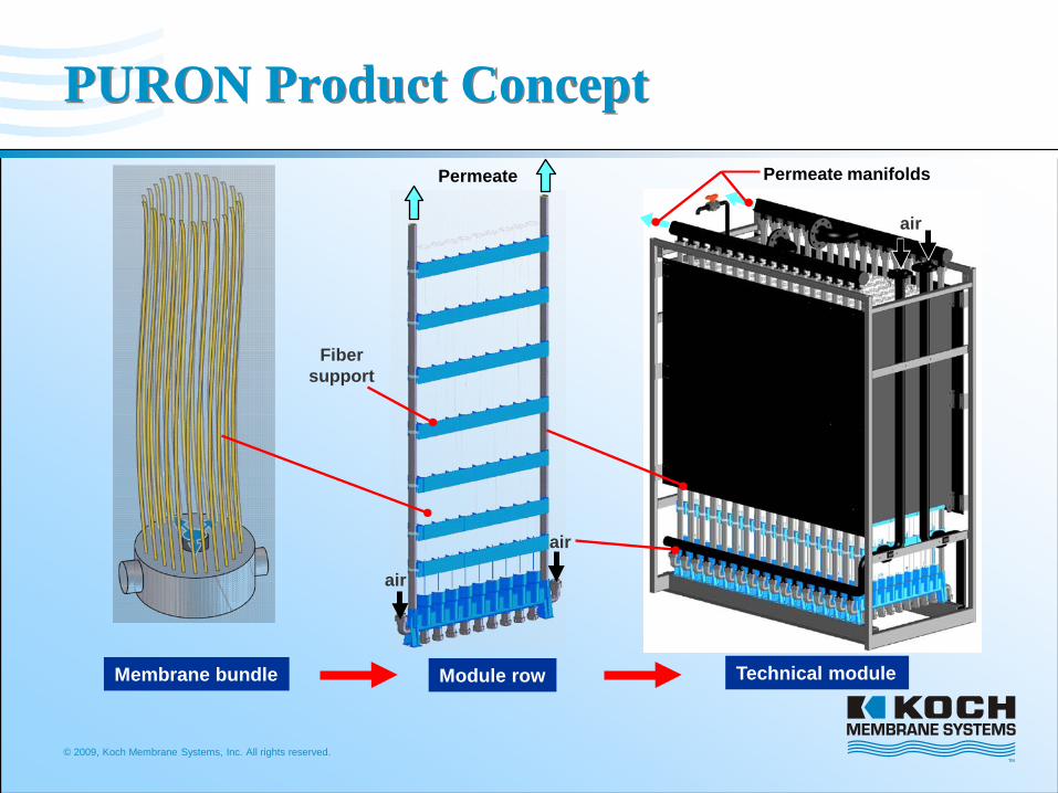
PURON Product Concept
Permeate
Individually sealed hollow
fibers
One side potting
Reduced clogging and sludging
Reduced energy consumption for aeration
main advantages
© 2009, Koch Membrane Systems, Inc. All rights reserved.
PURON Product Concept
Fibersupport
air
Permeate
Membrane bundle Module row Technical module
air
Permeate manifolds
air

© 2009, Koch Membrane Systems, Inc. All rights reserved.
PURON ModuleDescription
• Standard Sizes– 30 m2
– 250 m2
– 500 m2
– 1500 m2
• Integrated permeate and aeration headers
• Available hardware to permit easy installation with both DIN and US piping
© 2009, Koch Membrane Systems, Inc. All rights reserved
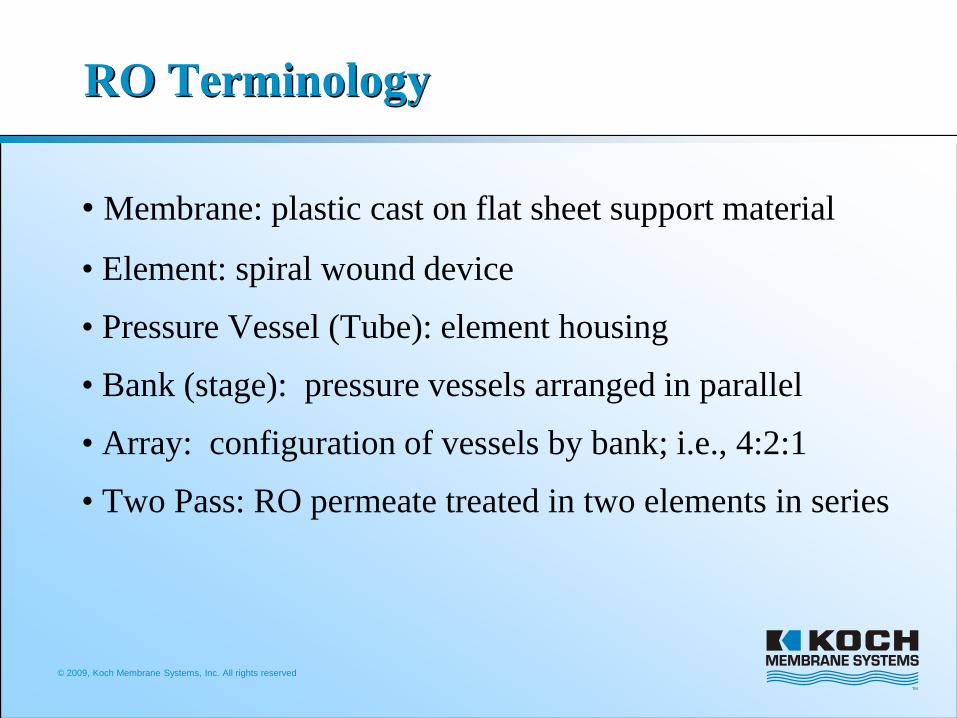
RO Terminology
• Membrane: plastic cast on flat sheet support material
• Element: spiral wound device
• Pressure Vessel (Tube): element housing
• Bank (stage): pressure vessels arranged in parallel
• Array: configuration of vessels by bank; i.e., 4:2:1
• Two Pass: RO permeate treated in two elements in series
© 2009, Koch Membrane Systems, Inc. All rights reserved
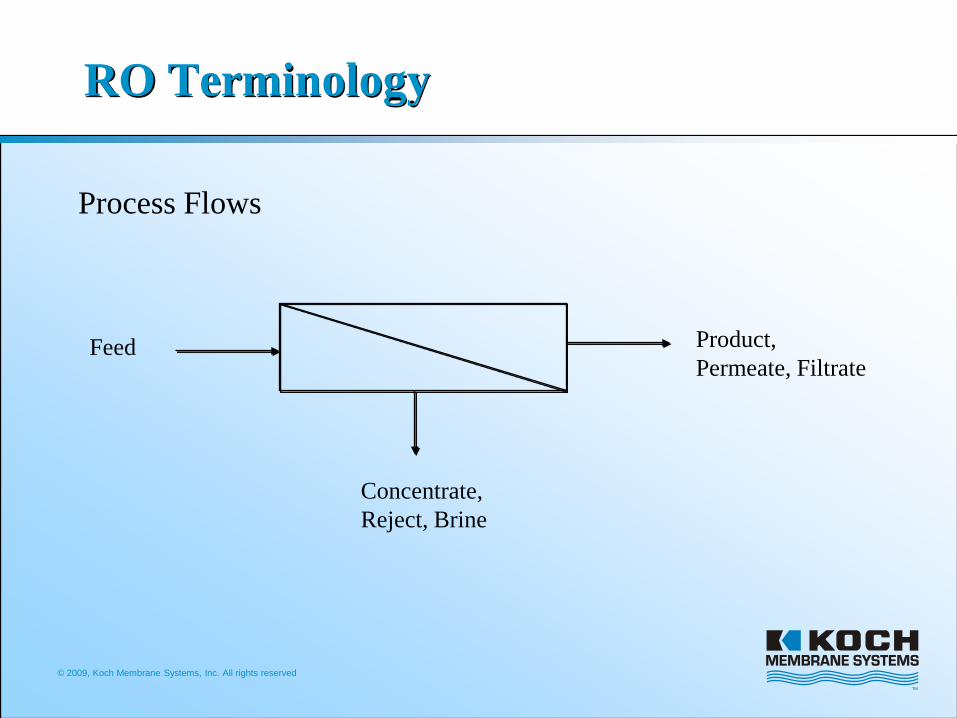
RO Terminology
Process Flows
Product, Permeate, Filtrate
Concentrate, Reject, Brine
Feed
© 2009, Koch Membrane Systems, Inc. All rights reserved
RO Terminology
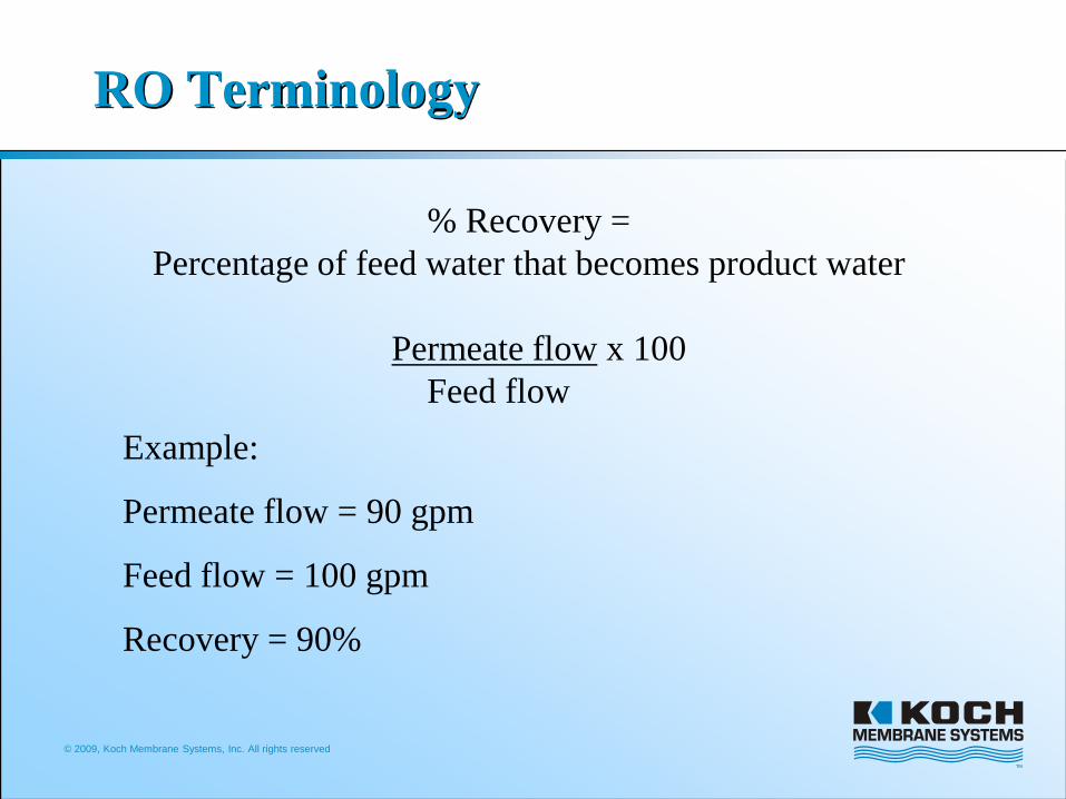
% Recovery =Percentage of feed water that becomes product water
Permeate flow x 100Feed flow
Example:
Permeate flow = 90 gpm
Feed flow = 100 gpm
Recovery = 90%
© 2009, Koch Membrane Systems, Inc. All rights reserved
RO Terminology
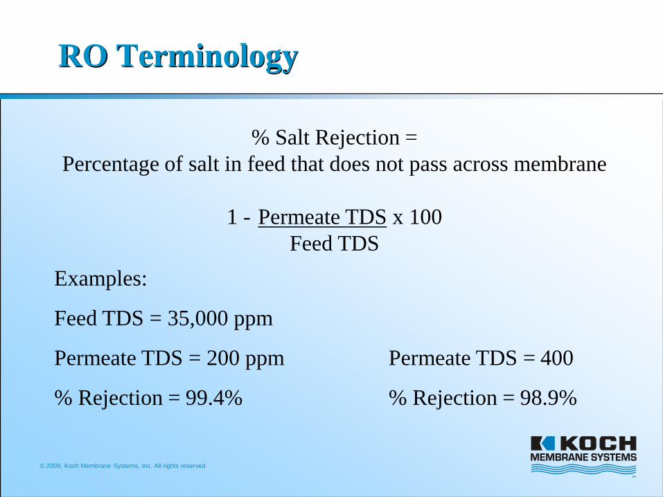
% Salt Rejection = Percentage of salt in feed that does not pass across membrane
1 - Permeate TDS x 100Feed TDS
Examples:
Feed TDS = 35,000 ppm
Permeate TDS = 200 ppm Permeate TDS = 400
% Rejection = 99.4% % Rejection = 98.9%
© 2009, Koch Membrane Systems, Inc. All rights reserved
RO Terminology
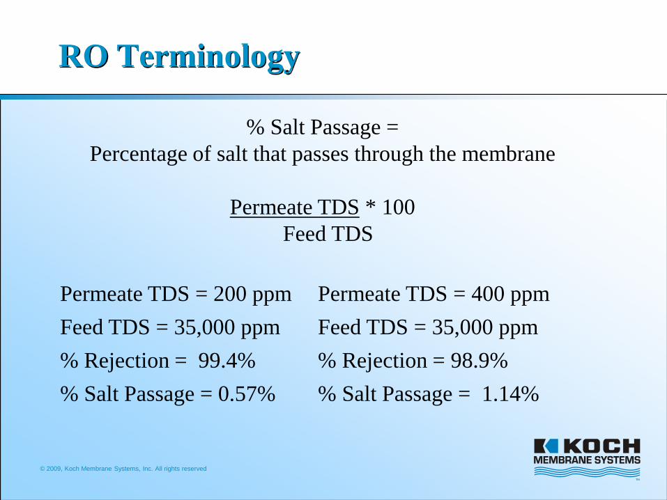
% Salt Passage =Percentage of salt that passes through the membrane
Permeate TDS * 100Feed TDS
Permeate TDS = 200 ppm Permeate TDS = 400 ppmFeed TDS = 35,000 ppm Feed TDS = 35,000 ppm% Rejection = 99.4% % Rejection = 98.9%% Salt Passage = 0.57% % Salt Passage = 1.14%

© 2009, Koch Membrane Systems, Inc. All rights reserved
RO Terminology
Concentrate
Permeate
High PressurePump
Feed
2nd Stage
1st Stage
100 gpm
50 gpm
25 gpm
75 gpm
50 gpm
25 gpm
Stage and Arrays (2/1 array)Each stage increases water recovery
© 2009, Koch Membrane Systems, Inc. All rights reserved
RO Terminology
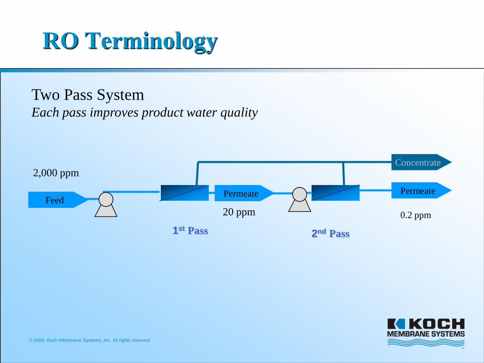
PermeateFeed
1st Pass
Permeate
2nd Pass
Concentrate2,000 ppm
20 ppm 0.2 ppm
Two Pass SystemEach pass improves product water quality
© 2009, Koch Membrane Systems, Inc. All rights reserved
RO Terminology
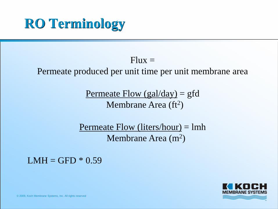
Flux = Permeate produced per unit time per unit membrane area
Permeate Flow (gal/day) = gfdMembrane Area (ft2)
Permeate Flow (liters/hour) = lmhMembrane Area (m2)
LMH = GFD * 0.59
© 2009, Koch Membrane Systems, Inc. All rights reserved
RO Terminology
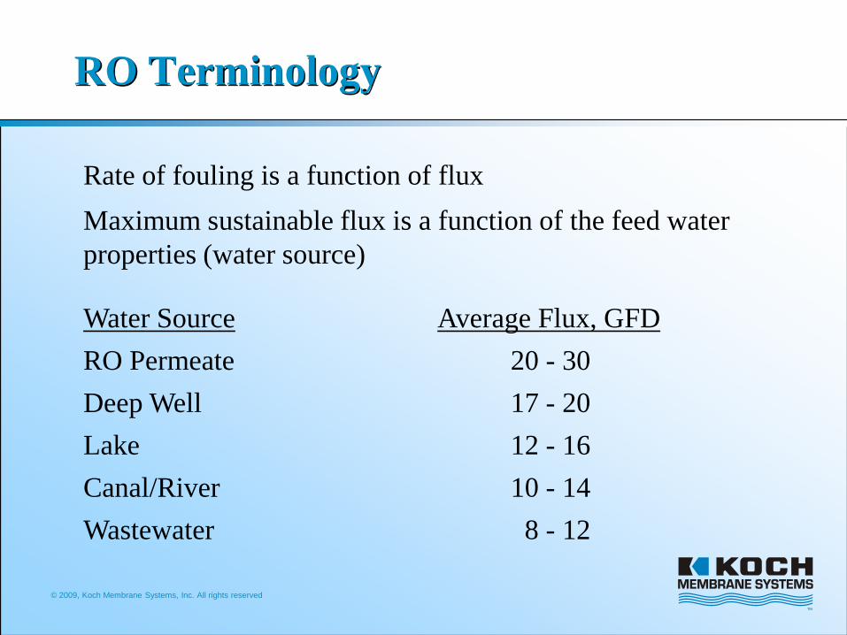
Rate of fouling is a function of fluxMaximum sustainable flux is a function of the feed water properties (water source)
Water Source Average Flux, GFDRO Permeate 20 - 30Deep Well 17 - 20Lake 12 - 16Canal/River 10 - 14Wastewater 8 - 12
© 2009, Koch Membrane Systems, Inc. All rights reserved
RO Terminology
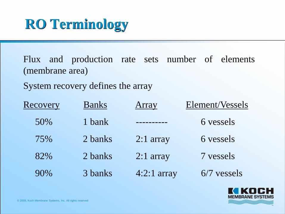
Flux and production rate sets number of elements(membrane area)System recovery defines the array
Recovery Banks Array Element/Vessels
50% 1 bank ---------- 6 vessels
75% 2 banks 2:1 array 6 vessels
82% 2 banks 2:1 array 7 vessels
90% 3 banks 4:2:1 array 6/7 vessels
© 2009, Koch Membrane Systems, Inc. All rights reserved.
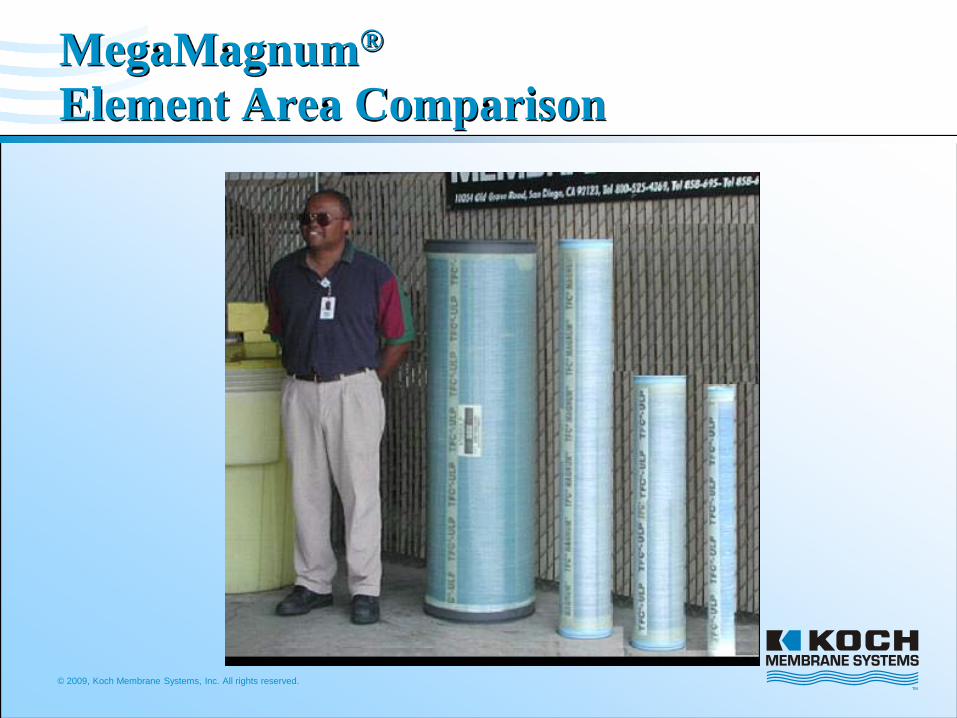
MegaMagnum®
Element Area Comparison

© 2009, Koch Membrane Systems, Inc. All rights reserved.
Nominal Diameter (inches)
Element OD (inches) Core OD (inches) Available Area
(inches2) Area Ratio
18.00 17.2 3.5 223 5.117.25 16.4 3.5 201 4.516.00 15.2 3.5 172 3.912.75 11.6 2.5 101 2.38.00 7.65 1.62 44 1
223 in244 in2
Large DiameterRO Element Comparison
18 inch comparison: Factor of five scaling compared to 8 inchNominal 30% more membrane area than 16 inch
© 2009, Koch Membrane Systems, Inc. All rights reserved.
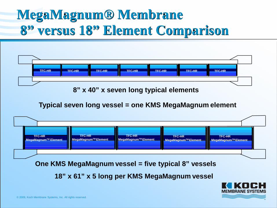
MegaMagnum® Membrane8” versus 18” Element Comparison
8” x 40” x seven long typical elements
TFC-HR TFC-HR TFC-HR TFC-HR TFC-HR TFC-HRTFC-HR
Typical seven long vessel = one KMS MegaMagnum element
TFC-HR MegaMagnumTM Element
18” x 61” x 5 long per KMS MegaMagnum vessel
TFC-HR MegaMagnumTM Element
TFC-HR MegaMagnumTM Element
TFC-HR MegaMagnumTM Element
TFC-HR MegaMagnumTM Element
One KMS MegaMagnum vessel = five typical 8” vessels
© 2009, Koch Membrane Systems, Inc. All rights reserved.
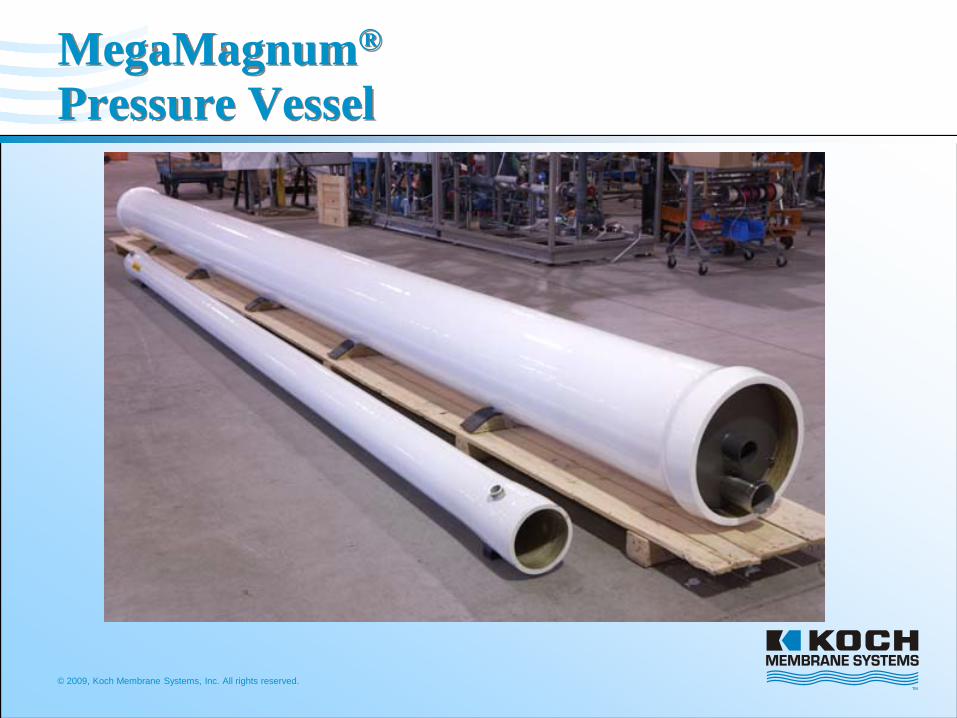
MegaMagnum®
Pressure Vessel
© 2009, Koch Membrane Systems, Inc. All rights reserved.
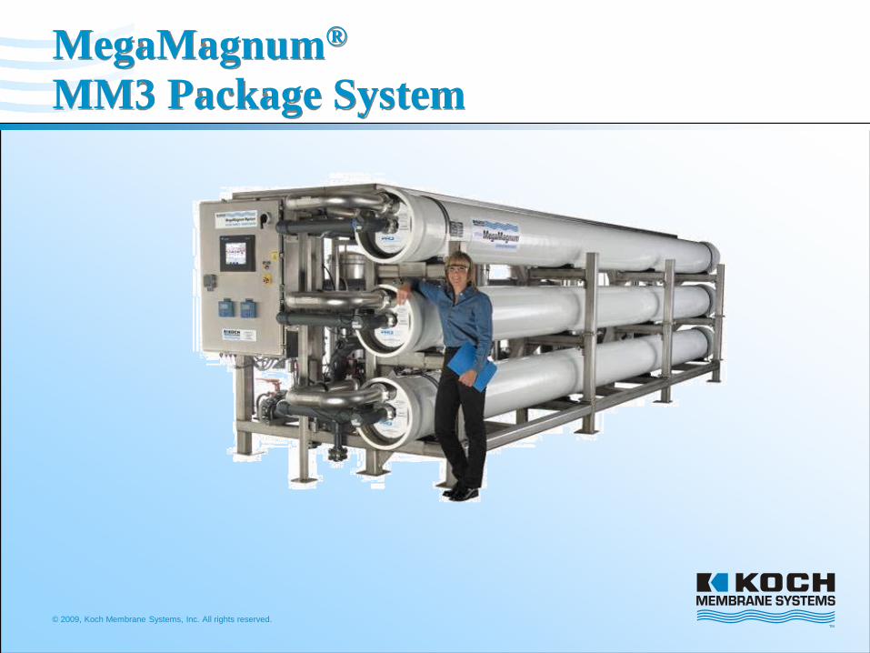
MegaMagnum®
MM3 Package System
© 2009, Koch Membrane Systems, Inc. All rights reserved
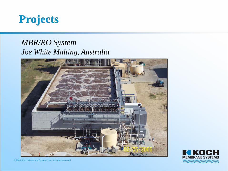
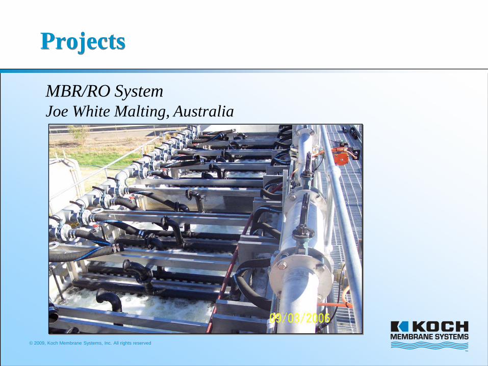
Projects
MBR/RO SystemJoe White Malting, Australia
© 2009, Koch Membrane Systems, Inc. All rights reserved
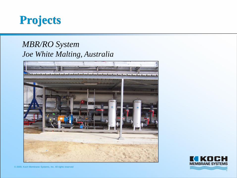
Projects
MBR/RO SystemJoe White Malting, Australia

© 2009, Koch Membrane Systems, Inc. All rights reserved
Projects
MBR/RO SystemJoe White Malting, Australia
© 2009, Koch Membrane Systems, Inc. All rights reserved
Projects
MBR/RO SystemJoe White Malting, Australia
© 2009, Koch Membrane Systems, Inc. All rights reserved
Projects
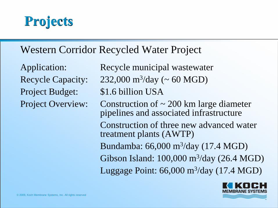
Western Corridor Recycled Water ProjectApplication: Recycle municipal wastewater Recycle Capacity: 232,000 m3/day (~ 60 MGD)Project Budget: $1.6 billion USAProject Overview: Construction of ~ 200 km large diameter
pipelines and associated infrastructureConstruction of three new advanced water treatment plants (AWTP)Bundamba: 66,000 m3/day (17.4 MGD)Gibson Island: 100,000 m3/day (26.4 MGD)Luggage Point: 66,000 m3/day (17.4 MGD)
© 2009, Koch Membrane Systems, Inc. All rights reserved
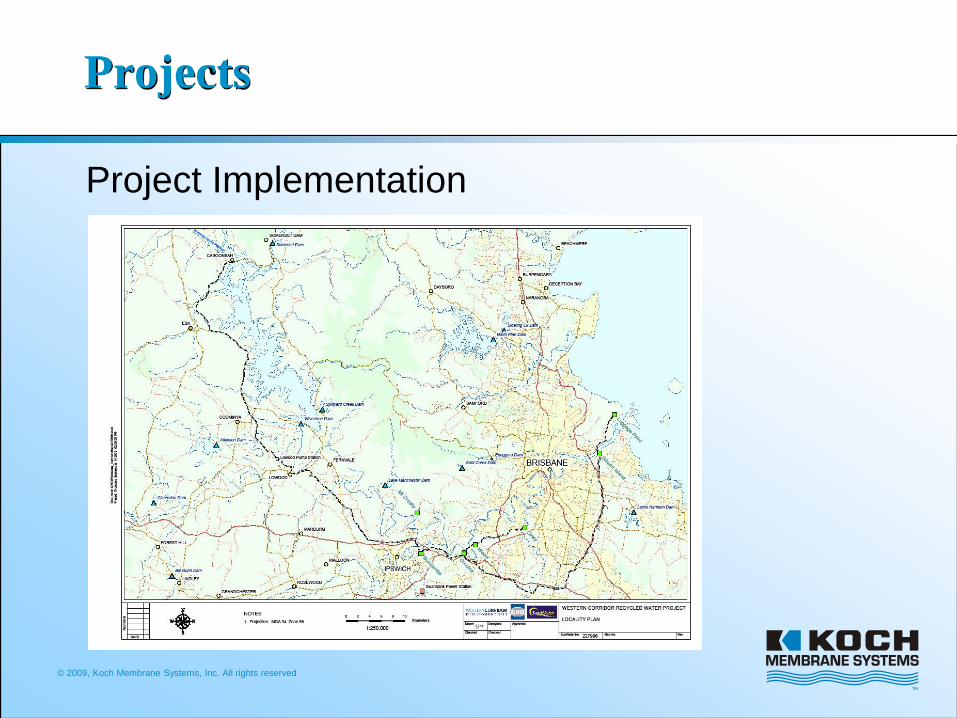
Projects
Project ImplementationRecycle water from the Bundamba AWTP is pumped to and used as cooling tower and boiler makeup water at the Swanbank and Tarong Power StationsRecycled water replaces water that is otherwise removed from municipal water reservoirs; thereby replenishing the local drinking water supply.
© 2009, Koch Membrane Systems, Inc. All rights reserved
Projects
Project Implementation
© 2009, Koch Membrane Systems, Inc. All rights reserved
Projects
Project DescriptionFeed Water: Secondary clarified sewage (flocculation)Multi-stage advanced treatment process
Microfiltration (MF)Reverse osmosis (RO)
Advanced oxidation (UV/Peroxide)
Disinfection and Stabilization
© 2009, Koch Membrane Systems, Inc. All rights reserved
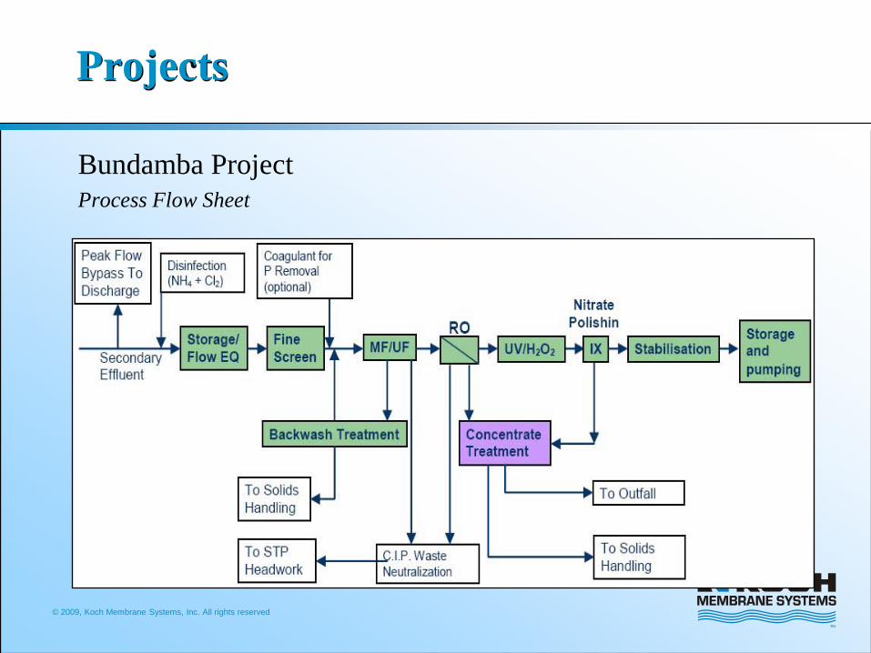
Projects
Bundamba ProjectProcess Flow Sheet
© 2009, Koch Membrane Systems, Inc. All rights reserved
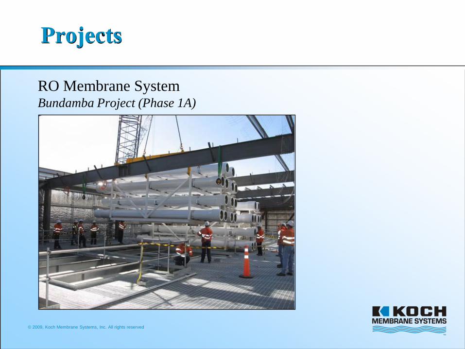
Projects
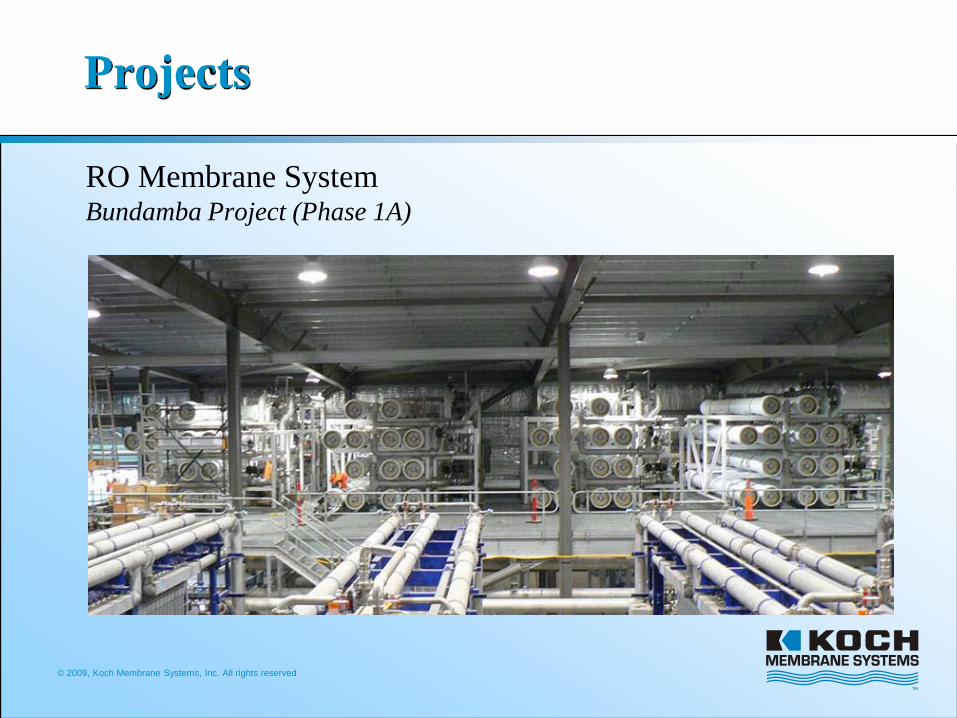
RO Membrane SystemBundamba Project (Phase 1A)
© 2009, Koch Membrane Systems, Inc. All rights reserved
Projects
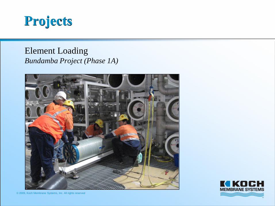
Element LoadingBundamba Project (Phase 1A)

© 2009, Koch Membrane Systems, Inc. All rights reserved
Projects
MF Membrane SystemBundamba Project (Phase 1A)
© 2009, Koch Membrane Systems, Inc. All rights reserved
Projects
RO Membrane SystemBundamba Project (Phase 1A)
© 2009, Koch Membrane Systems, Inc. All rights reserved
Projects
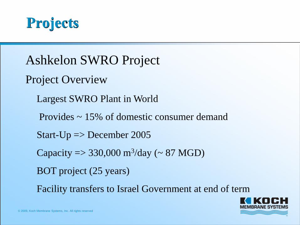
Ashkelon SWRO ProjectProject Overview
Largest SWRO Plant in World
Provides ~ 15% of domestic consumer demand
Start-Up => December 2005
Capacity => 330,000 m3/day (~ 87 MGD)
BOT project (25 years)
Facility transfers to Israel Government at end of term
© 2009, Koch Membrane Systems, Inc. All rights reserved
Projects
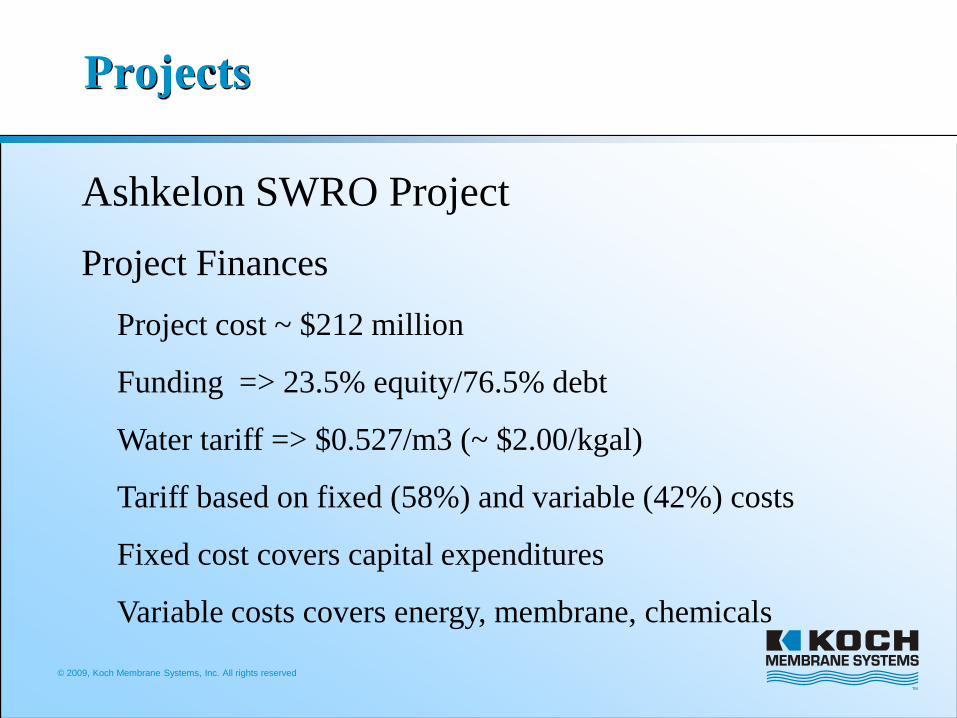
Ashkelon SWRO ProjectProject Finances
Project cost ~ $212 million
Funding => 23.5% equity/76.5% debt
Water tariff => $0.527/m3 (~ $2.00/kgal)
Tariff based on fixed (58%) and variable (42%) costs
Fixed cost covers capital expenditures
Variable costs covers energy, membrane, chemicals
© 2009, Koch Membrane Systems, Inc. All rights reserved
Projects
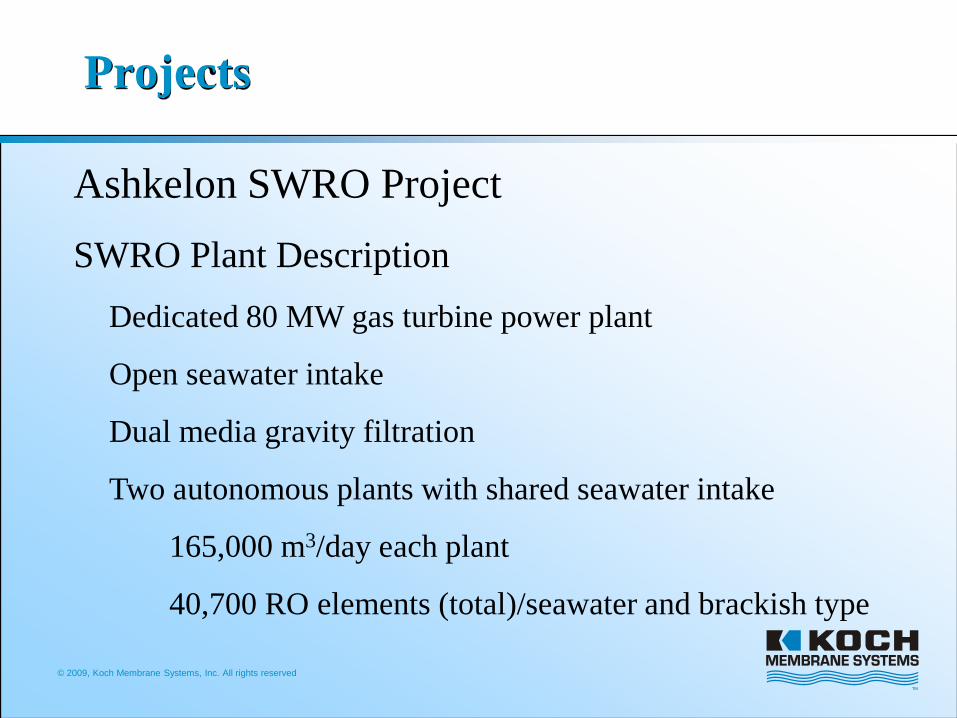
Ashkelon SWRO ProjectSWRO Plant Description
Dedicated 80 MW gas turbine power plant
Open seawater intake
Dual media gravity filtration
Two autonomous plants with shared seawater intake
165,000 m3/day each plant
40,700 RO elements (total)/seawater and brackish type
© 2009, Koch Membrane Systems, Inc. All rights reserved
Projects
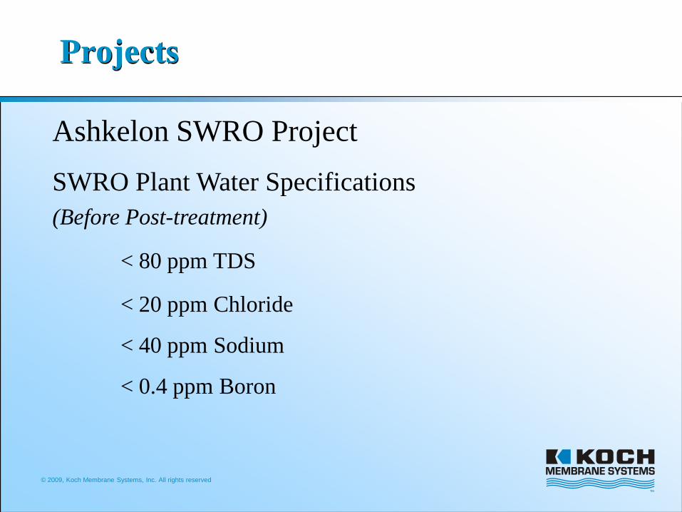
Ashkelon SWRO ProjectSWRO Plant Water Specifications (Before Post-treatment)
< 80 ppm TDS
< 20 ppm Chloride
< 40 ppm Sodium
< 0.4 ppm Boron

© 2009, Koch Membrane Systems, Inc. All rights reserved
Projects
Ashkelon SWRO ProjectOverview of RO Facilityhttp://www.water-technology.net/projects
© 2009, Koch Membrane Systems, Inc. All rights reserved
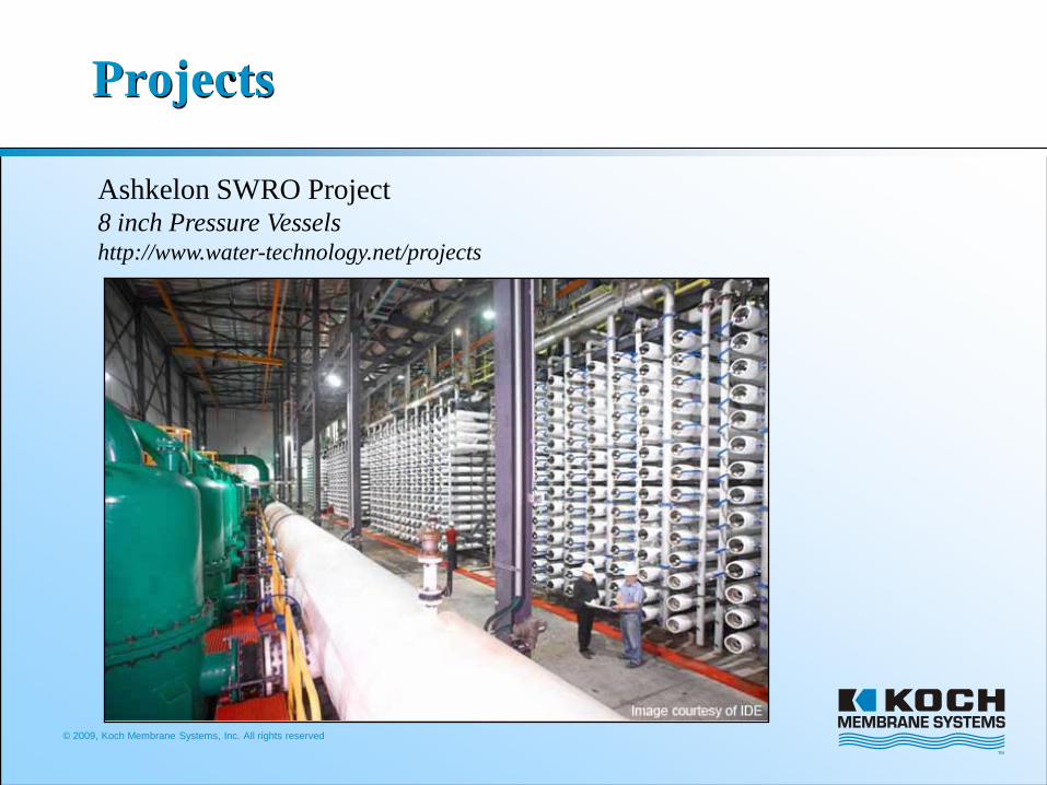
Projects
Ashkelon SWRO Project8 inch Pressure Vesselshttp://www.water-technology.net/projects

© 2009, Koch Membrane Systems, Inc. All rights reserved
Projects
Ashkelon SWRO ProjectDWEER Energy Recovery Devicehttp://www.water-technology.net/projects