2600t series pressure transmitter - abb group · 4 2600t series pressure transmitter ss/261gs/as_1...
TRANSCRIPT

Data SheetSS/261GS/AS_1
Base accuracy: ±0.15 %
Span limits– 0.3 to 60000kPa; 1.2inH2O – 0.3 to 3000kPa abs; 2.25mm
Reliable sensing system codigital technologies– provides large turn down rat
Stainless steel housing– optimized for rough environm– extreme robust
Flexible configuration facilit– Local zero and span button– Local configuration with key– Remote configuration with h
based software
Full compliance with PED C
2600T Series Pressure TransmitterModel 261GS Gauge
Model 261AS Absolutestandard overload
to 8700psiHg to 435psia
upled with very latest
io up to 20:1
ent
ies
s on LCD indicatorand terminal or PC
ategory III
ABB 2600T SeriesEngineered solutions
for all applications
2600T Series Pressure Transmitter SS/261GS/AS_1Model 261GS, 261AS
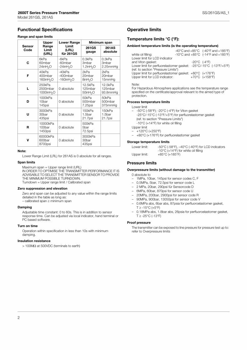
Functional SpecificationsRange and span limits
Note:
Lower Range Limit (LRL) for 261AS is 0 absolute for all ranges.
Span limits
Maximum span = Upper range limit (URL)IN ORDER TO OPTIMISE THE TRANSMITTER PERFORMANCE IT IS ADVISABLE TO SELECT THE TRANSMITTER SENSOR TO PROVIDE THE MINIMUM POSSIBLE TURNDOWN.Turndown = Upper range limit / Calibrated span
Zero suppression and elevation
Zero and span can be adjusted to any value within the range limits detailed in the table as long as:– calibrated span ≥ minimum span
Damping
Adjustable time constant: 0 to 60s. This is in addition to sensor response time. Can be adjusted via local indicator, hand terminal or PC based software.
Turn on time
Operation within specification in less than 10s with minimum damping.
Insulation resistance
> 100MΩ at 500VDC (terminals to earth)
Operative limits
Temperature limits °C (°F):
Ambient temperature limits (is the operating temperature)
-40°C and +85°C (-40°F and +185°F)white oil filling: -10°C and +85°C (-14°F and +185°F)Lower limit for LCD indicatorand Viton gasket: -20°C (-4°F)Lower limit for perfluorelastomer gasket: -25°C/-15°C (-13°F/+5°F) (ref. to section "Pressure Limits")Upper limit for perfluorelastomer gasket: +80°C (+176°F)Upper limit for LCD indicator: +70°C (+158°F)
Note:For Hazardous Atmosphere applications see the temperature range specified on the certificate/approval relevant to the aimed type of protection.
Process temperature limits
Lower limit– -50°C (-58°F); -20°C (-4°F) for Viton gasket
-25°C/-15°C (-13°F/+5°F) for perfluorelastomer gasket (ref. to section "Pressure Limits") -10°C (+14°F) for white oil filling
Upper limit– +120°C (+250°F)– +80°C (+176°F) for perfluorelastomer gasket
Storage temperature limits
Lower limit: -50°C (-58°F), –40°C (-40°F) for LCD indicators -10°C (+14°F) for white oil filling
Upper limit: +85°C (+185°F)
Pressure limits
Overpressure limits (without damage to the transmitter)
0 absolute to– 1MPa, 10bar, 145psi for sensor codes C, F– 0.5MPa, 5bar, 72.5psi for sensor code L– 2 MPa, 20bar, 290psi für Sensorcode D– 6MPa, 60bar, 870psi for sensor code U – 20MPa, 200bar, 2900psi for sensor code R – 90MPa, 900bar, 13050psi for sensor code V– 0.6MPa abs, 6bar abs, 87psia for perfluoroelastomer gasket,
T ≥ -15°C (+5°F)– 0.18MPa abs, 1.8bar abs, 26psia for perfluoroelastomer gasket,
T ≥ -25°C (-13°F)
Proof pressure
The transmitter can be exposed to line pressure for pressure test up to: refer to Overpressure limits
SensorCode
UpperRangeLimit(URL)
Lower RangeLimit(LRL)
für 261GS
Minimum span
261GSgauge
261ASabsolute
C6kPa60mbar24inH2O
-6kPa-60mbar-24inH2O
0.3kPa3mbar1.2inH2O
0.3kPa3mbar2.25mmHg
F40kPa400mbar160inH2O
-40kPa-400mbar-160inH2O
2kPa20mbar8inH2O
2kPa20mbar15mmHg
L250kPa2500mbar1000inH2O
0 absolute12.5kPa125mbar50inH2O
12.5kPa125mbar93.8mmHg
D1000kPa10bar145psi
0 absolute50kPa500mbar7.25psi
50kPa500mbar375mmHg
U3000kPa30bar435psi
0 absolute150kPa1.5bar21.7psi
150kPa1.5bar21.7psi
R10000kPa100bar1450psi
0 absolute500kPa5bar72.5psi
V60000kPa600bar8700psi
0 absolute3000kPa30bar435psi
2

2600T Series Pressure Transmitter SS/261GS/AS_1Model 261GS, 261AS
Environmental limitsElectromagnetic compatibility (EMC)
Complies with EMC directive 89 / 336 / EECas well as with EN 61000-6-3 for emission andEN 61000-6-2 for immunity requirements and testFulfills NAMUR recommendation
Low voltage directive
Complies with 73 / 23 / EEC
Pressure equipment directive (PED)
Complies with 97 / 23 / EEC Category III module H.
Humidity
Relative humidity: up to 100%Condensing, icing: admissible
Vibration resistance
Accelerations up to 2g at frequency up to 1000Hz(according to IEC 60068–2–6)
Shock resistance (according to IEC 60068–2–27)
Acceleration: 50gDuration: 11ms
Wet and dust-laden atmospheres
The transmitter is dust and sand tight and protected against immersion effects as defined by IEC EN60529 (1989) to IP 67(IP 68, IP 69K on request) or by NEMA to 4X or by JIS to C0920.
Hazardous atmospheres
Transmitters with hazardous area electrical certification "Intrinsically safe EEx ia/ib" comply with the directive 94 / 9 / EC (ATEX)
Transmitter with 4 to 20mA output signal and HART communication
Marking (DIN EN 50 014): II 1/2 G EEx ia IIC T4…T6II 2 G EEx ib IIC T4…T6
Permissible ambient temperature depending on temperature class:Ambient Temperature Temperature class-40 to +85°C (-40 to +185 °F) T1 ... T4-40 to +71°C (-40 to +159 °F) T5-40 to +56°C (-40 to +132 °F) T6
orMarking (DIN EN 50 014): II 1/2 D IP65 T95°
supplied intrinsically safe Ex iaII 2 D IP65 T95°supplied intrinsically safe Ex ib
Permissible ambient temperature:-40 to +85°C (-40 to +185 °F)
Supply and signal circuit type of protection Intrinsic SafetyEEx ia/ib IIB/IIC with maximum values:Ui = 30VIi = 130mAPi = 0.8W
effective internal capacitance:Ci = 10nFeffective internal inductance: Li = 10µH
Factory Mutual (FM) (pending)
Transmitter with 4 to 20mA output signal and HART communication
Intrinsically safe: Class I, II and III; Division 1; Groups A, B, C, D, E, F, GClass I; Zone 0; AEx ia Group IIC T6; T4
Non -incentive Class I, II, and III, Division 2, Groups A, B, C, D, F, G
Degree of protection : NEMA Type 4X (indoor or outdoor)
Canadian Standard (CSA) (pending)
Transmitter with 4 to 20mA output signal and HART communication
Intrinsically safe: Class I, II and III; Division 1; Groups A, B, C, D, E, F, GClass I; Zone 0; AEx ia Group IIC T6; T4
Non -incentive Class I, II, and III, Division 2, Groups A, B, C, D, F, G
Degree of protection : NEMA Type 4X (indoor or outdoor)
3

2600T Series Pressure Transmitter SS/261GS/AS_1Model 261GS, 261AS
Electrical Characteristics and Options
HART digital communication and 4 to 20mA output
Power Supply
The transmitter operates from 10 to 42VDC with no load and is protected against reverse polarity connection (additional load allows operations over 42VDC). Minimum power supply is 11VDC with LCD indicator.For EEx ia and other intrinsically safe approval power supply must not exceed 30VDC.
Ripple
Maximum permissible voltage ripple of power supply during the communication:According to HART FSK physical layer specification Rev. 8.1
Load limitations
4 to 20mA and HART total loop resistance:
A minimum of 250Ω is required for HART communication.
Integral display (optional)
Digital Graphic LCD display for user-specific indication of:Gauge pressure / absolute pressure orpercentage of the output current oroutput current in mA orHART output (free choice of initial-, final value and unit)Diagnostic messages, alarms, errors and measuring range infringements are also displayed.Furthermore the LCD indicator can be used for configuration and parametrization of the transmitter via four keys.
Output signal
Two-wire, 4 to 20mA outputHART® communication provides digital process variable (%, mA or engineering units) superimposed on 4 to 20mA signal, with protocol based on Bell 202 FSK standard.
Output current limits (to NAMUR standard)
Overload condition- Lower limit: 3.8mA (configurable down to 3.5mA)- Upper limit: 20.5mA (configurable up to 22.5mA)
Alarm current
Min. alarm current: configurable from 3.5mA to 4mA, standard setting: 3.6mA
Max. alarm current: configurable from 20mA to 22.5mA, standard setting: 21mA
Standard setting: max. alarm current
SIL – Functional Safety (optional)
according to IEC 61508 / 61511
Device with Declaration of SIL Conformity for use in safety related applications up to SIL 2
Performance specificationsStated at reference condition to IEC 60770 ambient temperature of 20°C (68°F), relative humidity of 65%, atmospheric pressure of 1013hPa (1013mbar), zero based range for transmitter with isolating diaphragms ceramic or Hastelloy and silicone oil fill.Mode: linear, 4-20mA
Unless otherwise specified, errors are quoted as % of span.
The performances based to the Upper Range Limit (URL) are effected by the actual turndown (TD) as ratio between Upper Range Limit (URL) and calibrated span.
IT IS RECOMMENDED TO SELECT THE TRANSMITTER SENSOR CODE PROVIDING THE TURNDOWN VALUE AS LOWEST AS POSSIBLE TO OPTIMIZE PERFORMANCE CHARACTERISTICS.
Dynamic performance (according to IEC 61298–1 definition)
Dead time: 100 msTime constant (63.2% of total step change):– 150 ms for all sensors
Accuracy rating% of calibrated span, including combined effects of terminal based linearity, hysteresis and repeatability.
– ±0.15% for TD from 1:1 to 10:1
–
Operating influences
Ambient temperature
per 10 K (18 °F) change between the limits of -10°C to +60°C (+14°F to +140°F):±(0.15% URL + 0.15% span)
Supply voltage
Within voltage/load specified limits the total effect is less than 0.001% of URL per volt.
Load
Within load/voltage specified limits the total effect is negligible.
Radio frequency interference
Total effect: less than 0.3% of span from 80 to 1000MHz and for field strengths up to 10V/m when tested with unshielded conduit, with or without meter.
Stability
±0.10% of URL over a 12 month period
Vibration effect
±0.10% of URL (according to IEC 61298–3)
R kΩ( ) Supply voltage - min. operating voltage (VDC)22.5mA
------------------------------------------------------------------------------------------------------------------------=
for TD greater than > 10:10.15% 0.005 URLSpan------------ 0.05%–×+
±
4

2600T Series Pressure Transmitter SS/261GS/AS_1Model 261GS, 261AS
Physical Specification
(Refer to ordering information sheets for variant availability related to specific model)
Materials
Process isolating diaphragms (*)
Ceramic (Al203) gold-plated; Hastelloy C276™; Hastelloy C276™ gold-plated; AISI 316 L ss.
Process connection (*)
AISI 316 L ss; Hastelloy C276™.
Gasket (only for sensor codes C, F)
Viton™, Perfluorelastomer, Perbunan (NBR).
Sensor fill fluid
Silicone oil; inert fill (Carbon fluoride); white oil (FDA).
Mounting bracket
AISI 316 L ss.
Sensor housing
AISI 316 L ss.
Electronic housing and covers
AISI 316 C ss.
Filter for atmosphere ventilation
plastic (standard), stainless steel
Cover O-ring
Neoprene™ (CR).
Tagging
Plastic data plate attached to the electronic housing.
CalibrationStandard: 0 to Upper Range Limit (URL)Optional: at specified range
Optional extras
Mounting brackets
For vertical and horizontal 60mm (2in) pipes or wall mounting.
Integral display
graphic display, plug-in rotatable LCD indicator
Supplemental customer tag
AISI 316 ss tag fastened to the transmitter with stainless steel wire for customer's tag data up to a maximum of 30 characters and spaces.
Cleaning procedure for oxygen service
Test Certificates (test, design, calibration, material traceability)
Manual language
™ Hastelloy is a Cabot Corporation trademark™ Viton is a Dupont de Nemour trademark
(*) Wetted parts of the transmitter
Process connections 1/2–14 NPT female or male; DIN EN837–1 G 1/2 B or G 1/2 B (HP) for convex seal; front bonded diaphragm; for ball valve.
Electrical connectionsone M16x1.5 threaded conduit entry, direct on housingor 1/2-14 NPT (without cable gland) or M20x1.5 (without cable gland)or Harting Han connectoror Miniature-connector (without plug socket)
Terminal block
HART version: two terminals for signal/supply voltage wiring up to 1.5mm² (16AWG).
Grounding (Option)
External 4mm² (12AWG) ground termination point.
Mounting positionTransmitter can be mounted in any position.
Mass (without options)0.7kg approx (1.54lb).Add 650g (1.43lb) for packing.
PackingCarton 24 x 14 x 19cm approx (10 x 6 x 8in).
Configuration
Transmitter with HART communication and 4 to 20 mA
Standard configuration
Transmitters are factory adjusted to customer's specific range. Adjusted range and tag number are marked on the type plate. If calibration range and tag data are not specified, the transmitter will be supplied configured as follows:
Any or all the above configurable parameters, including Lower range- value and Upper range-value, can be easily changed with the optional LCD indicator, using a HART hand–held communicator or by a PC, running the configuration software SMART VISION with DTM for 2600T.
4 mA Zero
20 mA Upper Range Limit (URL)
Output Linear
Damping 0,1s
Transmitter failure mode 21mA
LCD indicator (optional) 0…100%
5
2600T Series Pressure Transmitter SS/261GS/AS_1Model 261GS, 261AS
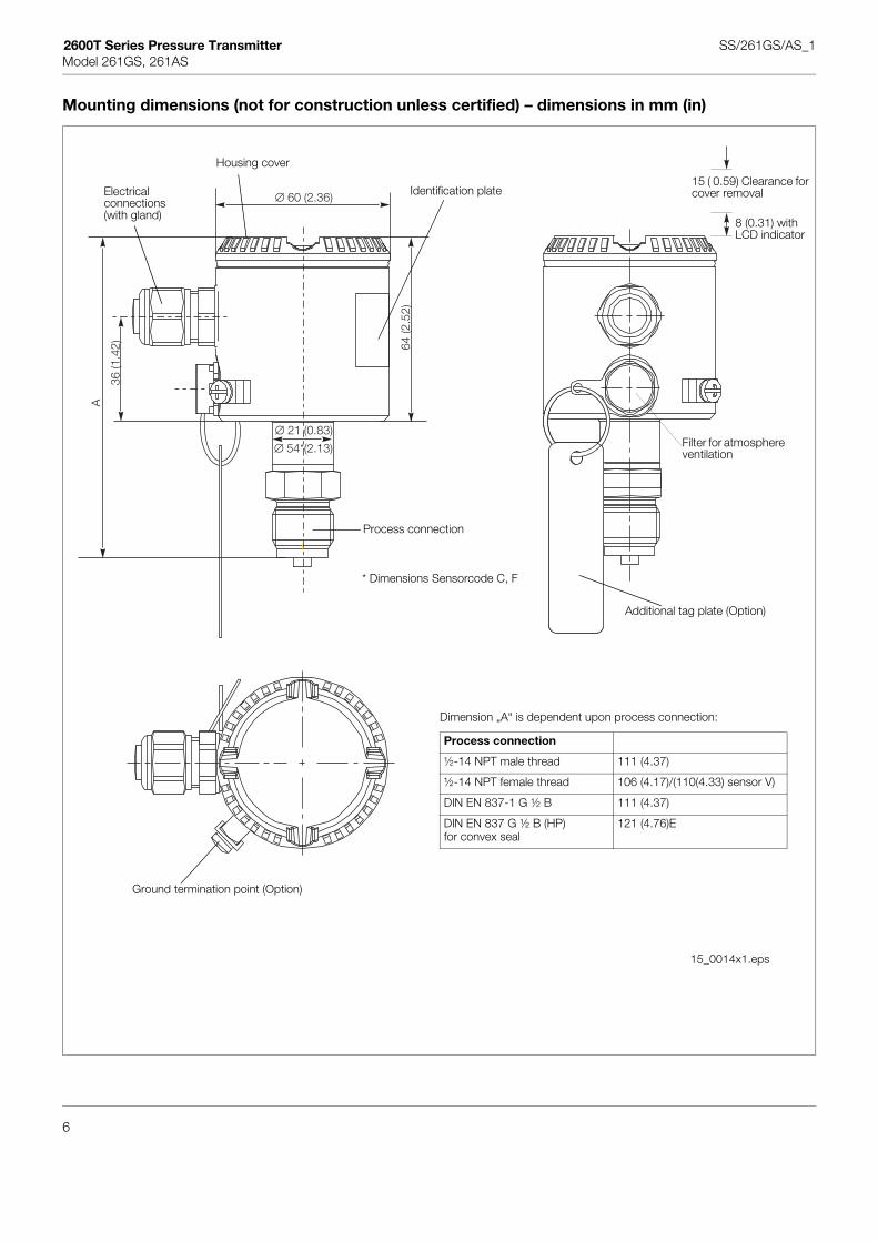
Mounting dimensions (not for construction unless certified) – dimensions in mm (in)
∅ 60 (2.36)
∅ 21 (0.83)
36 (1
.42) 64
(2.5
2)
A
∅ 54*(2.13)
Dimension „A“ is dependent upon process connection:
Process connection
½-14 NPT male thread 111 (4.37)
½-14 NPT female thread 106 (4.17)/(110(4.33) sensor V)
DIN EN 837-1 G ½ B 111 (4.37)
DIN EN 837 G ½ B (HP)for convex seal
121 (4.76)E
15_0014x1.eps
Housing cover
Identification plateElectricalconnections(with gland)
Additional tag plate (Option)
Process connection
Ground termination point (Option)
* Dimensions Sensorcode C, F
Filter for atmosphere ventilation
8 (0.31) with LCD indicator
15 ( 0.59) Clearance for cover removal
6

2600T Series Pressure Transmitter SS/261GS/AS_1Model 261GS, 261AS
Design with the options LCD indicator and Harting Han connector
∅ 60 (2.36)102 (4.02)
72 (2
.83)
36 (1
.42)
A +
8
∅ 21 (0.83)
∅ 54*(2.13)
Dimension „A“ is dependent upon process connection:
Process connection
½-14 NPT male thread 111 (4.37)
½-14 NPT female thread 106 (4.17)/(110(4.33) sensor V)
DIN EN 837-1 G ½ B 111 (4.37)
DIN EN 837 G ½ B (HP)for convex seal
121 (4.76)E
15_0015x1.eps
LCD indicatorhousing cover
* Dimensions Sensorcode C, F
7

2600T Series Pressure Transmitter SS/261GS/AS_1Model 261GS, 261AS
Transmitter with front bonded diaphragm
Transmitter with ball valve connection
A
0.1 A
∅ 50
∅ 21.3 -0.2
∅ 19.4 +0.1
∅ 18.2 +0.1
G ½
21
min
.10
.5
15-0
.2
∅ 60 (2.36)
36 (1
.42) 64
(2.5
2)
110
(4.3
3)
20 (0
.79)
10(0
.39)
∅ 18(0.71)
∅ 21 (0.83)
Weld-on adaptor and socketFront bonded diaphragm
Chamfer aftertapping
Burrless.
groove for O-Ring15x2
width acrossflats 27 mm
G 1/2 B
groove for sealing ringDIN 3869-2118.5x23.9x1.5
15_0018x1.eps M01401x2.eps
∅ 60 (2.36)
36 (1
.42)
64 (2
.52)
206
(8.1
1)
142
(5.5
9)
20(0
.79)
37 (1
.46)
29 (1
.14)
∅ 25(0.89)
∅ 25(0.89)
G 1in
∅ 29.6(1.17)
15_0019x1.eps
conical sealmetal/metalThe diaphragm is process-bonded.
washer
width acrossflats 36 mm
diaphragm∼∅: ∼20 (0.79)
8

2600T Series Pressure Transmitter SS/261GS/AS_1Model 261GS, 261AS
Possible mounting with bracket (optional)
Note: Bracket both for pipe and wall monting provides four holes of 10.5 mm (0.41 in) diameter on square with 72 mm (2.84 in) side
86.5
(3.4
)
∅60
(2.3
6) (m
ax. 6
3 (2
.48)
)
86.5
(3.4
)
72 (2.83)
20(0.79)
68 (2
.68)
(Sen
sor
Cod
e C
, F)
35 (1
.38)
(Sen
sor
Cod
e L,
D, U
, R, V
)
12.5(0.49)
15(0.59)
60 (2
.36)
72 (2.83)
15_0017x1.eps
2 in Pipe-/Wall-mounting
9

2600T Series Pressure Transmitter SS/261GS/AS_1Model 261GS, 261AS
Electrical connections
Standard Terminal block
Connector Versions
+
-
+
+
--691HT
A B C
1
D E F
2
G H I
3
J K L
4
M N O
5
P Q R
6
S T U
7V W X
8Y Z #
9
@ % & /
0+-
PV
REVIEW SERIALLINK
TRIM
F1 F2 F3 F4
CONF
15_0023x1.eps
Button to lower range value and upper range value
+SignalScrew terminal for 0.5…1.5mm²-wire
-SignalScrew terminal for 0.5…1.5mm²-wire
Cable entry
Ground termination point (Option)
Ground
Hand-held-communicator
Optional
Receiver
Powersource
Line load
250 ohm min
21
- +
1
2
3
4
10(0.39)
13 (0.51)
M12
x1
Harting Han 8U pin identification(view onto socket)
male M12x1 miniature connector
1 = -2 = +
Mating female plug NOT SUPPLIED
15_0025x1.eps
10

2600T Series Pressure Transmitter SS/261GS/AS_1Model 261GS, 261AS
Basic ordering information
Gauge pressure transmitter Catalog No. CodeBASE ACCURACY 0,15% 261GSSensor–Span limits Overpressure limit0.3 and 6 kPa 3 and 60 mbar 1.2 and 24 in H2O 1 MPa, 145 psi C2 and 40 kPa 20 and 400 mbar 8 and 160 in H2O 1 MPa, 145 psi F12.5 and 250 kPa 125 a. 2500 mbar 50 and 1000 in H2O 0.5 MPa, 72.5 psi L50 and 1000 kPa 0.5 and 10 bar 7.25 and 145 psi 2 MPa, 290 psi D150 and 3000 kPa 1.5 and 30 bar 21.7 and 435 psi 6 MPa, 870 psi U500 and 10000 kPa 5 and 100 bar 72.5 and 1450 psi 20 MPa, 2900 psi R3000 and 60000 kPa 30 and 600 bar 435 and 8700 psi 90 MPa, 13050 psi VAbsolute pressure transmitter Catalog No. CodeBASE ACCURACY 0,15% 261ASSensor–Span limits Overpressure limit0.3 and 6 kPa 3 and 60 mbar 2.25 and 45 mmHg 1 MPa, 145 psi C2 and 40 kPa 20 and 400 mbar 15 and 300 mmHg 1 MPa, 145 psi F12.5 and 250 kPa 125 a. 2500 mbar 93.8 and 1875 mmHg 0.5 MPa, 72.5 psi L50 and 1000 kPa 0.5 and 10 bar 375 and 7500 mmHg 2 MPa, 290 psi D150 and 3000 kPa 1.5 and 30 bar 21.7 and 435 psi 6 MPa, 870 psi UDiaphragm material (wetted parts) / Fill fluidAISI 316 L ss Siliconoil NACE 2) S
only for front bonded diaphragmHastelloy C276 TM Siliconoil NACE 2) KHastelloy C276 TM gold-plated Siliconoil NACE 2) GAISI 316 L ss Inert fluid NACE 2) A
only for front bonded diaphragmHastelloy C276 TM Inert fluid NACE 1, 2) FHastelloy C276 TM gold-plated Inert fluid NACE 1, 2) EAISI 316 L ss White oil (FDA) NACE 2) N
only for front bonded diaphragmHastelloy C276 TM White oil (FDA) NACE 2) ZCeramic No filling NACE 3) JProcess connection material / Process connection (wetted parts)AISI 316 L ss 1/2-14 NPT female NACE BAISI 316 L ss DIN EN837-1 G 1/2 B NACE PAISI 316 L ss G 1/2 front bonded diaphragm NACE 2) SAISI 316 L ss 1/2-14 NPT male NACE TAISI 316 L ss DIN EN837-1 G 1/2 B (HP) for convex seal NACE 2) UAISI 316 L ss For ball valve connection NACE 2) VGasketViton TM NACE 1, 3) 5Perfluorelastomer (Pmax = 0.6 MPa) NACE 3) 6Buna 3) 8keine NACE 2) NElectronic housingHousing material Electrical connectionAISI 316 L ss M16x1,5 (with cable gland made of plastic) 2AISI 316 L ss 1/2-14 NPT (without cable gland) SAISI 316 L ss M20x1.5 (without cable gland) TAISI 316 L ss Harting Han connector 4) 3AISI 316 L ss Miniature-connector 4) ZOutput / Additional optionsHART-digital communication and 4 to 20 mA No additional options 5) HHART-digital communication and 4 to 20 mA Options requested 1
(to be ordered by "Additional ordering code")
1) Suitable for oxygen service (O2)2) Not available with sensor range 60 and 400 mbar3) Only available with sensor range 60 and 400 mbar4) Select type in additional ordering code5) Not available for electrical connection with connector
11

2600T Series Pressure Transmitter SS/261GS/AS_1Model 261GS, 261AS
Additional ordering information
Standard delivery items (can be differently specified by additional ordering code)– General purpose (no electrical certification)– No meter/display, no mounting bracket– English manual and labels– Configuration with kPa and deg. C units– No test, inspection or material traceability certificates
THE SELECTION OF SUITABLE WETTED PARTS AND FILLING FLUID FOR COMPATIBILITY WITH THE PROCESS MEDIA IS A CUSTOMER'S RESPONSIBILITY, IF NOT OTHERWISE NOTIFIED BEFORE MANUFACTURING.
CodeElectrical certificationATEX Group II Category 1/2 G – Intrinsic Safety EEx ia EHATEX Group II Category 1/2 D – Intrinsic Safety EEx ia (without cable gland) ELFactory Mutual (FM) – Intrinsically Safe EACanadian Standard Association (CSA) – Intrinsically Safe EDIntegral LCDDigital LCD integral display L1Electrical housing accessoriesHousing with external earthing/potential equalizing terminal AAM16x1,5 cable gland and atmosphere ventilation made of metal ABMounting bracket (shape and material)For pipe mounting AISI 316 L ss B2For wall mounting AISI 316 L ss B4Preparation procedureOxygen service cleaning (O2) P1
(Only available with inert fill and for sensor code C, F - Viton gasket)Pmax = 21 MPa/210 bar/3045 psi, Tmax = 60°C/140°F
Operating manualGerman M1Additional tag plateStainless steel, laser printed I1Certificates/approvalsInspection certificate EN 10204-3.1.B of calibration C1Inspection certificate EN 10204-3.1.B of the cleanliness stage according to DIN 25410 C3Inspection certificate EN 10204-3.1.B of helium leakage test of the sensor module C4Inspection certificate EN 10204-3.1.B of the pressure test C5Certificate of compliance with the order EN 10204-2.1 of instrument design C6SIL 2 - classification CLMaterial traceabilityCertificate of compliance with the order EN 10204-2.1 of process wetted parts H1Inspection certificate EN 10204-3.1.B of the pressure-bearing and process wetted parts with analysis H3
certificates as material verification (minor parts with Factory Certificate acc. to "EN 10 204")Test report EN 10204-2.2 of the pressure bearing and process wetted parts H4ConnectorMiniature plug M12x1 (without plug socket) U2Harting Han 8U – straight entry 6) U3
6) Only available for electrical connection with Harting Han connector and output HART
12


SS
/261
GS
/AS
_1
ABB has Sales & Customer Supportexpertise in over 100 countries worldwide.
www.abb.com
The Company’s policy is one of continuous productimprovement and the right is reserved to modify the
information contained herein without notice.
Printed in the Fed. Rep. of Germany (04.05)
© ABB 2005
ABB Ltd.Howard Road, St. NeotsCambridgeshire, PE19 8EUUKTel: +44 (0)1480 475321Fax: +44 (0)1480 217948
ABB Inc.125 E. County Line RoadWarminster, PA 18974USATel: +1 215 674 6000Fax: +1 215 674 7183
ABB Automation Products GmbHSchillerstraße 7232425 MindenGermanyTel: +49 551 905-534Fax: +49 551 905-555