280-1 5)4-)5 cataloghi/idraulica/en/f280-d1.pdf · (-0)15-215 b5 b4 == b2 b3 indicator port (option...
TRANSCRIPT
HYDRAULICFILTRATION
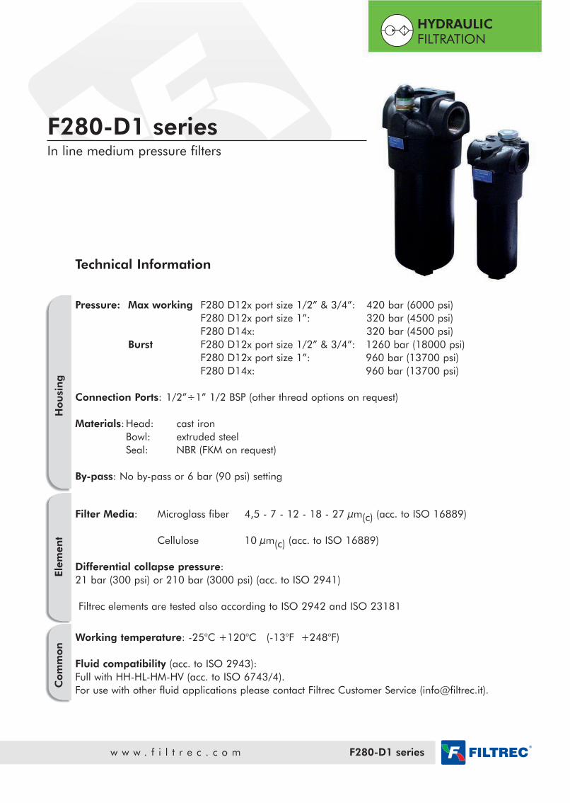
F280-D1 seriesIn line medium pressure filters
w w w . f i l t r e c . c o m F280-D1 series
Hou
sin
gEle
men
tC
om
mon
Technical Information
Pressure: Max working F280 D12x port size 1/2” & 3/4”: 420 bar (6000 psi)F280 D12x port size 1”: 320 bar (4500 psi) F280 D14x: 320 bar (4500 psi)
Burst F280 D12x port size 1/2” & 3/4”: 1260 bar (18000 psi)F280 D12x port size 1”: 960 bar (13700 psi) F280 D14x: 960 bar (13700 psi)
Connection Ports: 1/2”÷1” 1/2 BSP (other thread options on request)
Materials: Head: cast ironBowl: extruded steel Seal: NBR (FKM on request)
By-pass: No by-pass or 6 bar (90 psi) setting
Filter Media: Microglass fiber 4,5 - 7 - 12 - 18 - 27 µm(c) (acc. to ISO 16889)
Cellulose 10 µm(c) (acc. to ISO 16889)
Differential collapse pressure:21 bar (300 psi) or 210 bar (3000 psi) (acc. to ISO 2941)
Filtrec elements are tested also according to ISO 2942 and ISO 23181
Working temperature: -25°C +120°C (-13°F +248°F)
Fluid compatibility (acc. to ISO 2943):Full with HH-HL-HM-HV (acc. to ISO 6743/4).For use with other fluid applications please contact Filtrec Customer Service ([email protected]).
For different thread options please checkavailability with Filtrec Customer Service.
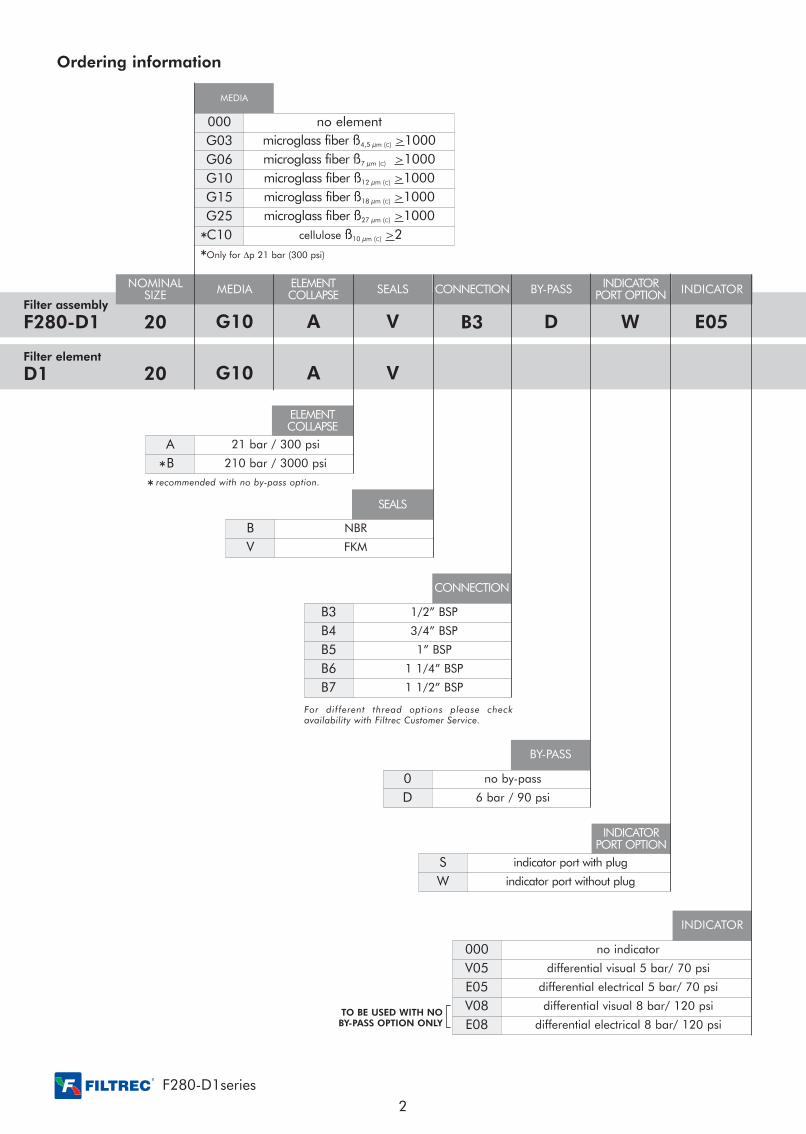
A 21 bar / 300 psi
B 210 bar / 3000 psi
F280-D1series
Ordering information
Filter assembly
F280-D1 20
NOMINALSIZE
G10
MEDIA
MEDIA
A
ELEMENTCOLLAPSE
Filter element
D1 20 G10 A V
V
SEALS
ELEMENTCOLLAPSE
B NBR
V FKM
SEALS
B3
CONNECTION
CONNECTION
D
BY-PASS
BY-PASS
W
INDICATORPORT OPTION
INDICATOR
000 no element
G03 microglass fiber ß4,5 µm (C) >1000
G06 microglass fiber ß7 µm (C) >1000
G10 microglass fiber ß12 µm (C) >1000
G15 microglass fiber ß18 µm (C) >1000
G25 microglass fiber ß27 µm (C) >1000
C10 cellulose ß10 µm (C) >2
B3 1/2” BSP
B4 3/4” BSP
B5 1” BSP
B6 1 1/4” BSP
B7 1 1/2” BSP
0 no by-pass
D 6 bar / 90 psi
S indicator port with plug
W indicator port without plug
E05
INDICATOR
000 no indicator
V05 differential visual 5 bar/ 70 psi
E05 differential electrical 5 bar/ 70 psi
V08 differential visual 8 bar/ 120 psi
E08 differential electrical 8 bar/ 120 psi
Only for Dp 21 bar (300 psi)
TO BE USED WITH NOBY-PASS OPTION ONLY
**
*recommended with no by-pass option.*
INDICATORPORT OPTION
2

Overall dimensions
B5B4
= =
B2B3
Indicator port(option T)
Ø F x depth Ø F x depth4+1 holes 3 holes
Indicator portoption S
Indicator portoption S
element removalR
element removalR
A A
L1
D1
B5==
B2
B6B6= =
B1
H1
30
H2 H2
B1
H1
Drain 30
FORF280-D143
ONLY
CODE A B1 B2 B3 B4 B5 B6 D1 F H1 H2 L1 R WEIGHT
F280-D120 1/2” BSP
3/4” BSP
1”BSP
22,5 47,5 43,5 27,5
25 60,6
70
M10x15
200
92 90 110
3,5 Kg
F280-D124 243 4,2 Kg
F280-D121 293 4,5 Kg
F280-D140
1 1/4” BSP
1 1/2” BSP40 55 -- -- 107
248
129 140 130
9,0 Kg
F280-D141 341 9,5 Kg
F280-D142 461 14,4 Kg
F280-D143 554 18,8 Kg
For different thread options please contact Filtrec Customer Service.
Nominal size
F280-D1 series
F280-D120/24/21
3

Flow rate (gpm)
Flow rate (l/min)
∆p (b
ar)
∆p (p
si)
Flow rate (gpm)
Flow rate (l/min)
∆p (b
ar)
∆p (p
si)
Flow rate (gpm)
Flow rate (l/min)
∆p (b
ar)
∆p (p
si)
Flow rate (gpm)
Flow rate (l/min)
∆p (b
ar)
∆p (p
si)
Flow rate (gpm)
Flow rate (l/min)
∆p (b
ar)
∆p (p
si)
Flow rate (gpm)
Flow rate (l/min)
∆p (b
ar)
∆p (p
si)
Flow rate (gpm)
Flow rate (l/min)
0 155 10 20 30
0 20 40 60 10080 120
0.4
0.0
0.8
1.2
2
1.6
55
00
1010
1515
2020
2525
C10
0.00
0.4
0.8
20 40 60 80 100 120
C10
00
55
1010
2
1.2
1.6
0 5 10
2020
1515
2525
15 20 30
0.4
0.00 20 40 60
0.8
1.2
0
1.6
2105
80 100 120
C10
00
55
1010
1515
2020
302015
2525
2
0.4
0.00
0.8
20 40 60
1.2
1.6
0.4
0
0.00
5 10
20 40 60
0.8
1.2
0
1.6
2105
0.00
0.4
0.8
20 40 60
12080 100
55
00
1010
1515
2020
2525
2015 30
80 100 12000
55
1010
1515
2020
302015
2525
80 100 12000
55
1010
2
1.2
1.6
0 5 10
2020
1515
2525
15 20 30
G25
G15
G10
G06
G03
G25
G15G10
G06
G03
G25G15
G10
G06
G03
G25
G15
G10
G06
G03
G15
G10
G06
G03
G15
G10
G06
G03
G25
G25
∆p (b
ar)
∆p (p
si)
0.00 20 40 60
1
0.2
0.4
0.8
0.6
0 5 10
80 100 1200
5
2.5
7.5
10
12.5
15 20 30 15
B3
B4
B5
Housing F280-D120/24/21PRESSURE DROP THROUGHTHE FILTER HOUSING
PRESSURE DROP THROUGHTHE CLEAN FILTER ELEMENT
Element D124-..-B Element D124-..-A
Element D120-..-BElement D120-..-A
Element D121-..-BElement D121-..-A
The Pressure Drop through the filter housing isgoverned by the port, not the bowl length and the oilviscosity.
The Pressure Drop through the filter element is relatedboth to the internal diameter of the filter element and tothe filter media; this value is affected by the oil viscosi-ty in a roughly proportional way: e.g. when the Dpvalue from the curve is 0,2 bar and a 46 cSt oil is used,the corresponding value is 0,31 (=0,2 x 46/30) bar.
Pressure drop diagrams
The total Pressure Drop (Dp) value is obtained by adding the Dp values of filter housing and filter element at the given flowrate. This ideally should not exceed 1,0 bar (14,5 psi) and should never exceed 1/3 of the set value of the by-pass valve.
F280-D1series
4
Flow rate (gpm)
Flow rate (l/min)
∆p (b
ar)
∆p (p
si)
Flow rate (gpm)
Flow rate (l/min)
∆p (b
ar)
∆p (p
si)
Flow rate (gpm)
Flow rate (l/min)
∆p (b
ar)
∆p (p
si)
Flow rate (gpm)
Flow rate (l/min)
∆p (b
ar)
∆p (p
si)
Flow rate (gpm)
Flow rate (l/min)
∆p (b
ar)
∆p (p
si)
Flow rate (gpm)
Flow rate (l/min)
∆p (b
ar)
∆p (p
si)
Flow rate (gpm)
Flow rate (l/min)0 15050 100 300250200
0.4
0.0
0.8
1.2
2
1.6
5
0
10
15
20
25
0 10 20 30 40 50 60 70
0 70 140 280210 350
0 3010 20 40 50 60 70 80 90
0.0
0.8
1.2
2
1.6
5
0
10
15
20
25
0 15050 100 300250200
0 10 20 30 40 50 60 70
0.4
0.0
0.8
1.2
2
1.6
5
0
10
15
20
25
15
1407000.0
0.40.4
0.8
350210 2800
5
10
1.6
1.2
20 10 20 30 40 706050 80 90
20
25
C10
G25
G15
G10
G06
G03
C10
G25G15
G10
G06
G03
G25
G15
G10G06G03
G25
G15
G10
G06
G03
0 80 160 320240 400
0 6020 40 80 100
0.0
0.4
1.2
0.8
1.6
0
5
10
15
20
0.00
0.4
80 160
0.8
1.2
1.60 20 40
20
400240 3200
5
10
15
8060 100
C10
G25
G15
G10
G06
G03
G25
G15
G10
G06
G03
0
0
∆p (b
ar)
0.0
0.2
0.4
0.6
0.8
10
400240 32016080
5 ∆p (p
si)
2.5
0
7.5
804020 60 100
B6
B7
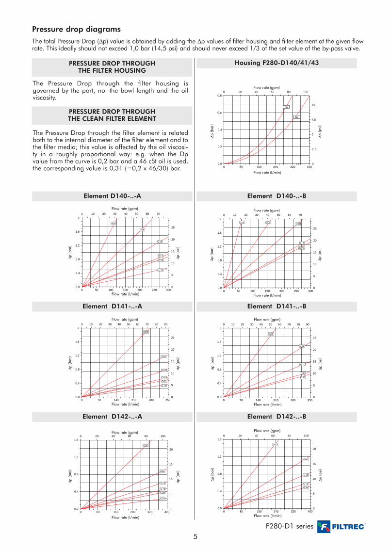
Housing F280-D140/41/43PRESSURE DROP THROUGHTHE FILTER HOUSING
PRESSURE DROP THROUGHTHE CLEAN FILTER ELEMENT
Element D141-..-B Element D141-..-A
Element D140-..-BElement D140-..-A
Element D142-..-BElement D142-..-A
The Pressure Drop through the filter housing isgoverned by the port, not the bowl length and the oilviscosity.
The Pressure Drop through the filter element is relatedboth to the internal diameter of the filter element and tothe filter media; this value is affected by the oil viscosi-ty in a roughly proportional way: e.g. when the Dpvalue from the curve is 0,2 bar and a 46 cSt oil is used,the corresponding value is 0,31 (=0,2 x 46/30) bar.
Pressure drop diagrams
The total Pressure Drop (Dp) value is obtained by adding the Dp values of filter housing and filter element at the given flowrate. This ideally should not exceed 1,0 bar (14,5 psi) and should never exceed 1/3 of the set value of the by-pass valve.
F280-D1 series
5
∆p (b
ar)
∆p (p
si)
Flow rate (gpm)
Flow rate (l/min)
∆p (b
ar)
∆p (p
si)
Flow rate (gpm)
Flow rate (l/min)
∆p (b
ar)
∆p (p
si)
Flow rate (gpm)
Flow rate (l/min)
∆p (b
ar)
∆p (p
si)
Flow rate (gpm)
Flow rate (l/min)
0.00 80 160
0.4
0.8
1.2
1.60 20 40
0400240 320
5
10
8060 100
20
15
16000.0
80
0.4
0.8
240 320
1.2
01.6
4020 60 80
5
4000
10
15
20
100
C10
G25G15
G10
G06
G03
G25
G15
G10
G06
G03
00 20 40 60 80 100
2
4
10
8
6
100 5 15 20
00120
50
100
30
B3
B4 - B5
0
2
4
6
8
10
12
0
50
100
150
0 15050 100 300250200
0 10 20 30 40 50 60 70
B6 - B7
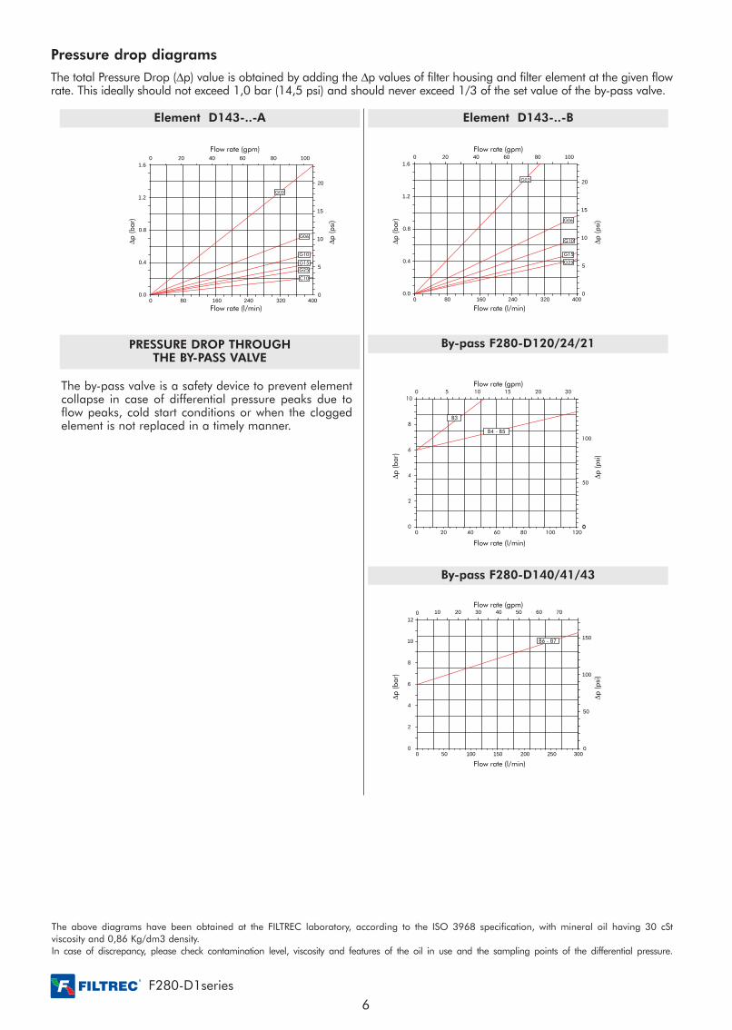
Element D143-..-BElement D143-..-A
PRESSURE DROP THROUGHTHE BY-PASS VALVE
By-pass F280-D120/24/21
By-pass F280-D140/41/43
The by-pass valve is a safety device to prevent elementcollapse in case of differential pressure peaks due toflow peaks, cold start conditions or when the cloggedelement is not replaced in a timely manner.
Pressure drop diagrams
The total Pressure Drop (Dp) value is obtained by adding the Dp values of filter housing and filter element at the given flowrate. This ideally should not exceed 1,0 bar (14,5 psi) and should never exceed 1/3 of the set value of the by-pass valve.
The above diagrams have been obtained at the FILTREC laboratory, according to the ISO 3968 specification, with mineral oil having 30 cStviscosity and 0,86 Kg/dm3 density.In case of discrepancy, please check contamination level, viscosity and features of the oil in use and the sampling points of the differential pressure.
F280-D1series
6
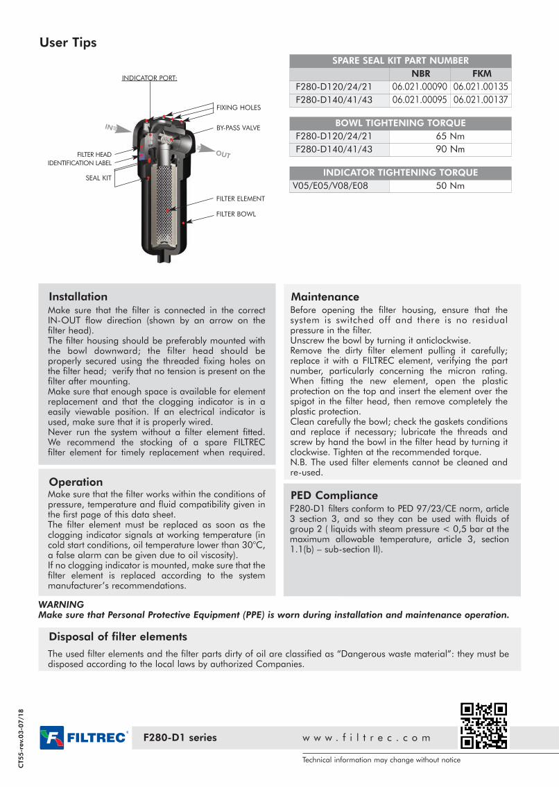
INDICATOR PORT:
FIXING HOLES
BY-PASS VALVE
OUT
IN
SEAL KIT
User Tips
SPARE SEAL KIT PART NUMBER
NBR FKM
F280-D120/24/21 06.021.00090 06.021.00135
F280-D140/41/43 06.021.00095 06.021.00137
BOWL TIGHTENING TORQUE
F280-D120/24/21 65 Nm
F280-D140/41/43 90 Nm
INDICATOR TIGHTENING TORQUE
V05/E05/V08/E08 50 Nm
InstallationMake sure that the filter is connected in the correctIN-OUT flow direction (shown by an arrow on thefilter head).The filter housing should be preferably mounted withthe bowl downward; the filter head should beproperly secured using the threaded fixing holes onthe filter head; verify that no tension is present on thefilter after mounting.Make sure that enough space is available for elementreplacement and that the clogging indicator is in aeasily viewable position. If an electrical indicator isused, make sure that it is properly wired.Never run the system without a filter element fitted. We recommend the stocking of a spare FILTRECfilter element for timely replacement when required.
MaintenanceBefore opening the filter housing, ensure that thesystem is switched off and there is no residualpressure in the filter.Unscrew the bowl by turning it anticlockwise.Remove the dirty filter element pulling it carefully;replace it with a FILTREC element, verifying the partnumber, particularly concerning the micron rating.When fitting the new element, open the plasticprotection on the top and insert the element over thespigot in the filter head, then remove completely theplastic protection.Clean carefully the bowl; check the gaskets conditionsand replace if necessary; lubricate the threads andscrew by hand the bowl in the filter head by turning itclockwise. Tighten at the recommended torque.N.B. The used filter elements cannot be cleaned andre-used.
OperationMake sure that the filter works within the conditions ofpressure, temperature and fluid compatibility given inthe first page of this data sheet.The filter element must be replaced as soon as theclogging indicator signals at working temperature (incold start conditions, oil temperature lower than 30°C,a false alarm can be given due to oil viscosity).If no clogging indicator is mounted, make sure that thefilter element is replaced according to the systemmanufacturer’s recommendations.
Disposal of filter elements
The used filter elements and the filter parts dirty of oil are classified as “Dangerous waste material”: they must bedisposed according to the local laws by authorized Companies.
WARNINGMake sure that Personal Protective Equipment (PPE) is worn during installation and maintenance operation.
PED ComplianceF280-D1 filters conform to PED 97/23/CE norm, article3 section 3, and so they can be used with fluids ofgroup 2 ( liquids with steam pressure < 0,5 bar at themaximum allowable temperature, article 3, section1.1(b) – sub-section II).
Technical information may change without notice
F280-D1 series w w w . f i l t r e c . c o m
CT55-r
ev.
03-0
7/1
8
FILTER ELEMENT
FILTER BOWL
IDENTIFICATION LABEL
FILTER HEAD