2d & 3d finite element method packages of cemtool for ... 2d & 3d finite element method...
TRANSCRIPT
1
2D & 3D Finite Element Method Packages ofCEMTool for Engineering PDE Problems
Choon Ki Ahn, Jung Hun Park, and Wook Hyun Kwon
Abstract— CEMTool is a command style design and analyzingpackage for scientific and technological algorithm and a matrix basedcomputation language. In this paper, we present new 2D & 3Dfinite element method (FEM) packages for CEMTool. We discussthe detailed structures and the important features of pre-processor,solver, and post-processor of CEMTool 2D & 3D FEM packages. Incontrast to the existing MATLAB PDE Toolbox, our proposed FEMpackages can deal with the combination of the reserved words. Also,we can control the mesh in a very effective way. With the introductionof new mesh generation algorithm and fast solving technique, ourFEM packages can guarantee the shorter computational time thanMATLAB PDE Toolbox. Consequently, with our new FEM packages,we can overcome some disadvantages or limitations of the existingMATLAB PDE Toolbox.
Keywords— CEMTool, Finite element method (FEM), Numericalanalysis, Partial differential equation (PDE)
I. INTRODUCTION
F INITE element method (FEM) provides a greater flexi-bility to model complex geometries than finite difference
and finite volume methods do. It has been widely used insolving structural, mechanical, heat transfer, and fluid dy-namics problems as well as problems of other disciplines.The advancement in computer technology enables us to solveeven larger system of equations, to formulate and assemblethe discrete approximation, and to display the results quicklyand convienently. This has also helped the finite elementmethod become a powerful tool. There are many kinds ofthe specialized FEM package for electromagnetics, structuralmechanics, heat transfer, and diffusion. Among the numericalgeneral-purpose packages for scientific computing, MATLABis one of the well-known package for science and engineeringthat performs mathematical and engineering computation. Asa tool to analyze the solution of partial differential equation(PDE) in MATLAB, the MATLAB PDE Toolbox [1] containsbasic tools for the study and solution of PDE in two spacedimensions (2D) and time, using the finite element method.Its command line functions and graphical user interface canbe used for mathematical modeling of PDE in special rangesof engineering and science applications. However, MATLABPDE Toolbox has some disadvantages or limitations as fol-lows: (1) It can deal with only constant coefficients. (2) Itrequires much computational time for mesh generation andsolving for the finite element analysis. (3) It has no meshcontrol and refinement algorithms. (4) It cannot be applied tothe practical analysis and design problems such as motor field
The authors are with the School of Electrical Engineering & ComputerScience, Seoul National University, Seoul, 151-742, Korea. (e-mail: [email protected])
analysis. (5) It can not be applied to three space dimensions(3D) problems.
As another powerful numerical general-purpose package,CEMTool integrates mathematical computing, visualization,and a powerful high-level language to provide a flexibleenvironment for technical computing [2], [3]. The powerfularchitecture makes it easy to use CEMTool and its companiontoolboxes to explore data, create algorithms, and create customtools that provide early insights and competitive advantages[4], [5], [6], [7], [8], [9]. In this paper, we present new FEMpackages which overcomes the some existing disadvantages orlimitations of MATLAB PDE Toolbox. Our 2D & 3D FEMpackages for CEMTool contains the lexical analyzer and theparser to deal with the general combination of reserved wordssuch as ”sin”, ”cos”, and ”convect”. That is why we can solvethe PDE represented by the combination of some reservedwords and mathematical operators [8], [9]. Also, it containsmesh refinement and control algorithms by the dense factor ingraphic user interface (GUI) FEM packages. Therefore, it ispossible to obtain the accurate results in a pre-defined region.In addition, it guarantees the high speed for finite elementanalysis with new mesh control algorithms and fast solvingtechniques. Finally, our FEM packages can applied to variouskinds of 3D engineering problems.
In Section 2, GUI based 2D CEMTool FEM package ispresented. In Section 3, we discuss command-mode FEMpackage for CEMTool. In Section 4, we introduce somestructures and features of 3D GUI CEMTool FEM package.The conclusion is given in Section 5.
II. GUI 2D FEM PACKAGE OF CEMTOOL
A. GUI 2D FEM Pre-processorCEMTool GUI 2D FEM pre-processor requires the informa-
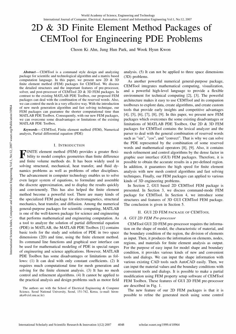
tion on the shape of model, the characteristic of material, andthe boundary condition of the region, the division of elementsas input. Then, it produces the information on elements, nodes,regions, and materials for finite element analysis as output.For the purpose of easy input for model shape and boundarycondition, it provides various kinds of new and convenienttools and dialogs. We can input the shape information withvarious existing CAD tools such AutoCAD easily. Then, wecan input the material values and the boundary conditions withconvenient tools and dialogs. It is possible to make a partialmodification using FEM property setup software of CEMToolFEM Toolbox. These features of GUI 2D FEM pre-processorare described in Fig. 1.
The new feature of our 2D FEM packages is that it ispossible to refine the generated mesh using some control
World Academy of Science, Engineering and TechnologyInternational Journal of Computer, Electrical, Automation, Control and Information Engineering Vol:1, No:12, 2007
4048International Scholarly and Scientific Research & Innovation 1(12) 2007 scholar.waset.org/1999.4/10964
Inte
rnat
iona
l Sci
ence
Ind
ex, C
ompu
ter
and
Info
rmat
ion
Eng
inee
ring
Vol
:1, N
o:12
, 200
7 w
aset
.org
/Pub
licat
ion/
1096
4
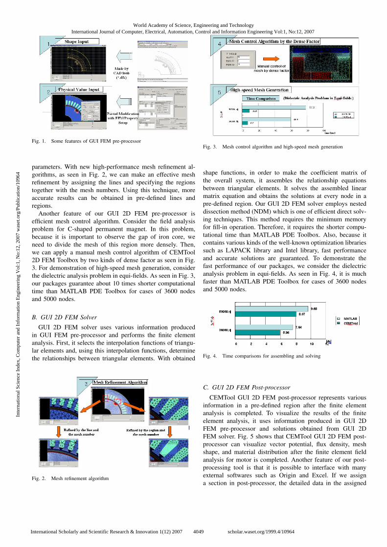
Fig. 1. Some features of GUI FEM pre-processor
parameters. With new high-performance mesh refinement al-gorithms, as seen in Fig. 2, we can make an effective meshrefinement by assigning the lines and specifying the regionstogether with the mesh numbers. Using this technique, moreaccurate results can be obtained in pre-defined lines andregions.
Another feature of our GUI 2D FEM pre-processor isefficient mesh control algorithm. Consider the field analysisproblem for C-shaped permanent magnet. In this problem,because it is important to observe the gap of iron core, weneed to divide the mesh of this region more densely. Then,we can apply a manual mesh control algorithm of CEMTool2D FEM Toolbox by two kinds of dense factor as seen in Fig.3. For demonstration of high-speed mesh generation, considerthe dielectric analysis problem in equi-fields. As seen in Fig. 3,our packages guarantee about 10 times shorter computationaltime than MATLAB PDE Toolbox for cases of 3600 nodesand 5000 nodes.
B. GUI 2D FEM Solver
GUI 2D FEM solver uses various information producedin GUI FEM pre-processor and performs the finite elementanalysis. First, it selects the interpolation functions of triangu-lar elements and, using this interpolation functions, determinethe relationships between triangular elements. With obtained
Fig. 2. Mesh refinement algorithm
Fig. 3. Mesh control algorithm and high-speed mesh generation
shape functions, in order to make the coefficient matrix ofthe overall system, it assembles the relationship equationsbetween triangular elements. It solves the assembled linearmatrix equation and obtains the solutions at every node in apre-defined region. Our GUI 2D FEM solver employs nesteddissection method (NDM) which is one of efficient direct solv-ing techniques. This method requires the minimum memoryfor fill-in operation. Therefore, it requires the shorter compu-tational time than MATLAB PDE Toolbox. Also, because itcontains various kinds of the well-known optimization librariessuch as LAPACK library and Intel library, fast performanceand accurate solutions are guaranteed. To demonstrate thefast performance of our packages, we consider the dielectricanalysis problem in equi-fields. As seen in Fig. 4, it is muchfaster than MATLAB PDE Toolbox for cases of 3600 nodesand 5000 nodes.
Fig. 4. Time comparisons for assembling and solving
C. GUI 2D FEM Post-processor
CEMTool GUI 2D FEM post-processor represents variousinformation in a pre-defined region after the finite elementanalysis is completed. To visualize the results of the finiteelement analysis, it uses information produced in GUI 2DFEM pre-processor and solutions obtained from GUI 2DFEM solver. Fig. 5 shows that CEMTool GUI 2D FEM post-processor can visualize vector potential, flux density, meshshape, and material distribution after the finite element fieldanalysis for motor is completed. Another feature of our post-processing tool is that it is possible to interface with manyexternal softwares such as Origin and Excel. If we assigna section in post-processor, the detailed data in the assigned
World Academy of Science, Engineering and TechnologyInternational Journal of Computer, Electrical, Automation, Control and Information Engineering Vol:1, No:12, 2007
4049International Scholarly and Scientific Research & Innovation 1(12) 2007 scholar.waset.org/1999.4/10964
Inte
rnat
iona
l Sci
ence
Ind
ex, C
ompu
ter
and
Info
rmat
ion
Eng
inee
ring
Vol
:1, N
o:12
, 200
7 w
aset
.org
/Pub
licat
ion/
1096
4

Mesh Plot Material Distribution
Vector Potential Flux Density
Fig. 5. Various plots for FEM post-processing
section can be saved in a text file. Therefore, we can use thisdata in the external softwares as seen in Fig. 6.
Interface Module(Excel, Origin, …)
Fig. 6. Interface with the external softwares
III. COMMMAND-MODE FEM PACKAGE FOR CEMTOOL
A. Basic Command-mode FEM Functions
When we need the solutions of PDE represented by equationform in a pre-defined region, it is not appropriate to usethe GUI based FEM package. The new FEM package whichcan solve the combination of the reserved words directly isa good choice for this situation. CEMTool command-modeFEM package has the lexical analyzer and the parser to dealwith the general combination of reserved words such as ”sin”,”cos”, and ”convect”. That is why we can solve PDE prob-lems represented by the combination of some reserved wordsand mathematical operators. Basically, the border function ofCEMTool FEM package requires some information on theboundary which is represented by the combination of thereserved words in x and y coordinates. After defining theboundary region, in order to generate the triangular meshbased on a Delaunay-Voronoi algorithm, we can employ themakemesh function of CEMTool FEM package by using theinformation on a maximum number of vertices as the onlyparameter of the makemesh function. For an assignment ofboundary conditions, the boundary condition function can beused with the information of the identification numbers andthe general boundary conditions represented by some reservedwords of CEMTool FEM package. In order to construct thesolutions of PDE we want to solve, we need the FEM solver
funtion of CEMTool FEM package with the information ofthe PDE which is represented by the combination of somebasic mathematical operators and some reserved words suchas ”laplace” and ”sin”. Because we employ the compilerbased technique in the command-mode FEM solve function,compared with MATLAB PDE Toolbox, we need not classifyPDEs we want to solve as elliptic equations, parabolic ones,and hyperbolic ones. Finally, the post-processing functionssuch as ”meshplot”, ”equi-potential plot”, and ”3D plot” canbe used to visualize the solutions of the PDE generated byCEMTool FEM package. The basic structure of CEMToolcommand-mode FEM package can be described in Fig. 7.In addition, it includes the dynamic FEM codes for real-timeanalysis of time-varying PDE problems.
Lexical Analyzer
Parser
Evaluation
FEM Routines
Token Generation
Parsing Tree GenerationFEM Command
� Solve general PDE� Apply general BC� Overcome the disadvantages
of MATLAB PDE Toolbox
Variables Generationand Inititialization
Post-processing
Fig. 7. CEMTool command-mode FEM package
B. 3D Post-processor of Commmand-mode FEM Package
In order to visualize the solutions of PDEs in a user-defined region, CEMTool command-mode FEM package hasthe powerful plot functions. The meshplot function showsthe triangular mesh generated by the makemesh functionwithout the information on height of the input shape. Also,the equiplot function of CEMTool FEM package can visualizethe equi-potential lines with the information on height ofthe input shape in 2D coordinates. The new feature of thepost-processing functions for CEMTool command-mode FEMpackage is 3D plot. This 3D plot uses OpenGL library for anenhanced 3D visualization. It shows the triangular meshes andthe equi-potential lines in 3D coordinates with the informationon height of the input shape. In Fig. 8, the 3D plot forPoisson equation in a user-defined rectangular region is given.In addition, it has the various functions such as rotation,transition, zoom-in, zoom-out, painting the faces, smooth view,and light function.
IV. GUI 3D FEM PACKAGE OF CEMTOOL
A. GUI 3D FEM Pre-processor
CEMTool 3D FEM pre-processor requires the 3D modelinginformation for a real shape that we want to analyze. Also, it
World Academy of Science, Engineering and TechnologyInternational Journal of Computer, Electrical, Automation, Control and Information Engineering Vol:1, No:12, 2007
4050International Scholarly and Scientific Research & Innovation 1(12) 2007 scholar.waset.org/1999.4/10964
Inte
rnat
iona
l Sci
ence
Ind
ex, C
ompu
ter
and
Info
rmat
ion
Eng
inee
ring
Vol
:1, N
o:12
, 200
7 w
aset
.org
/Pub
licat
ion/
1096
4
Major Functions
� Shift Function� Rotation Function� Zoom In� Zoom Out� Paint the Faces� Smooth View � Light Function
2D Post-processor2D Post-processor3D Post-processor3D Post-processor
Easy manipulation Easy manipulation Easy manipulation Easy manipulation
of mouseof mouseof mouseof mouse
OpenGL Library
Fig. 8. 3D Post-processor for command-mode FEM package
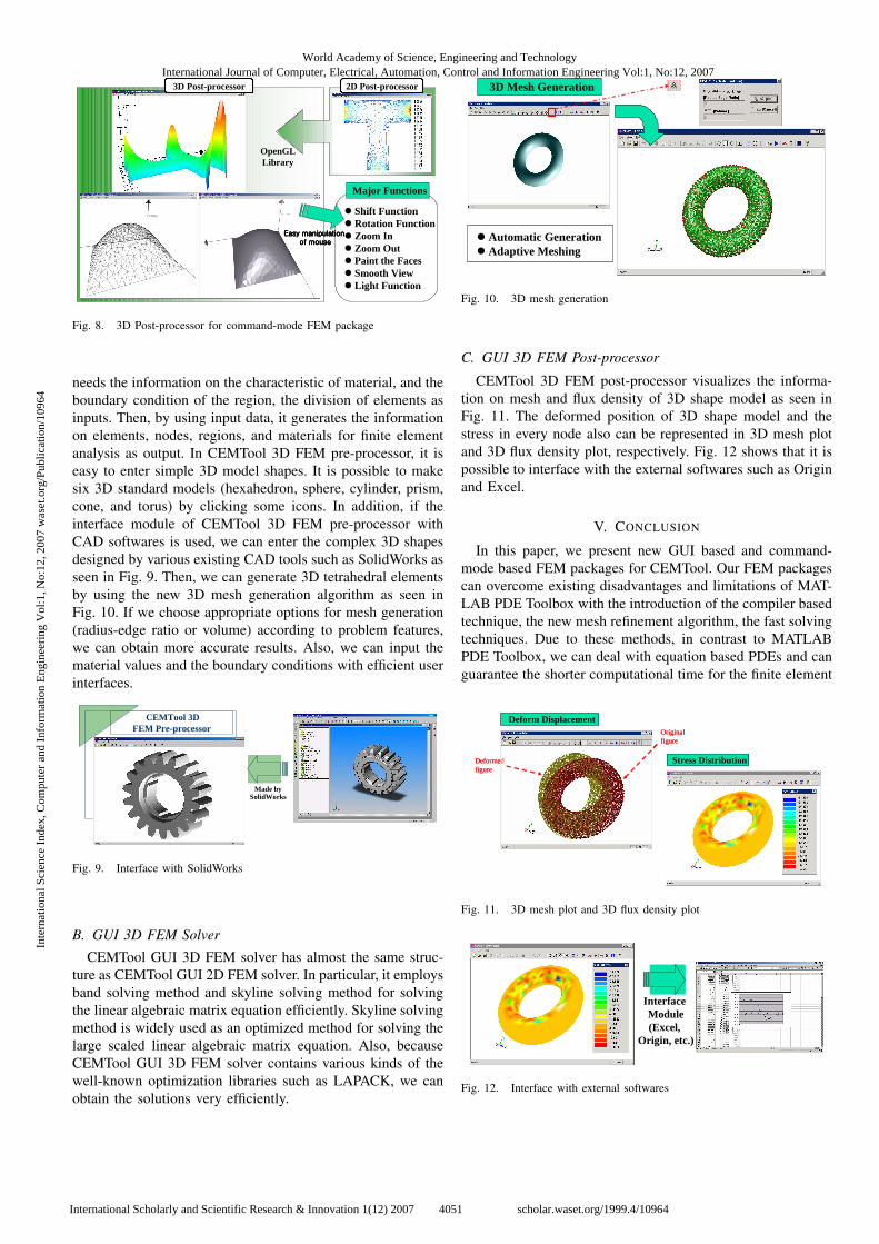
needs the information on the characteristic of material, and theboundary condition of the region, the division of elements asinputs. Then, by using input data, it generates the informationon elements, nodes, regions, and materials for finite elementanalysis as output. In CEMTool 3D FEM pre-processor, it iseasy to enter simple 3D model shapes. It is possible to makesix 3D standard models (hexahedron, sphere, cylinder, prism,cone, and torus) by clicking some icons. In addition, if theinterface module of CEMTool 3D FEM pre-processor withCAD softwares is used, we can enter the complex 3D shapesdesigned by various existing CAD tools such as SolidWorks asseen in Fig. 9. Then, we can generate 3D tetrahedral elementsby using the new 3D mesh generation algorithm as seen inFig. 10. If we choose appropriate options for mesh generation(radius-edge ratio or volume) according to problem features,we can obtain more accurate results. Also, we can input thematerial values and the boundary conditions with efficient userinterfaces.
CEMTool 3D FEM Pre-processor
Made bySolidWorks
Fig. 9. Interface with SolidWorks
B. GUI 3D FEM Solver
CEMTool GUI 3D FEM solver has almost the same struc-ture as CEMTool GUI 2D FEM solver. In particular, it employsband solving method and skyline solving method for solvingthe linear algebraic matrix equation efficiently. Skyline solvingmethod is widely used as an optimized method for solving thelarge scaled linear algebraic matrix equation. Also, becauseCEMTool GUI 3D FEM solver contains various kinds of thewell-known optimization libraries such as LAPACK, we canobtain the solutions very efficiently.
3D Mesh Generation
� Automatic Generation� Adaptive Meshing
Fig. 10. 3D mesh generation
C. GUI 3D FEM Post-processor
CEMTool 3D FEM post-processor visualizes the informa-tion on mesh and flux density of 3D shape model as seen inFig. 11. The deformed position of 3D shape model and thestress in every node also can be represented in 3D mesh plotand 3D flux density plot, respectively. Fig. 12 shows that it ispossible to interface with the external softwares such as Originand Excel.
V. CONCLUSION
In this paper, we present new GUI based and command-mode based FEM packages for CEMTool. Our FEM packagescan overcome existing disadvantages and limitations of MAT-LAB PDE Toolbox with the introduction of the compiler basedtechnique, the new mesh refinement algorithm, the fast solvingtechniques. Due to these methods, in contrast to MATLABPDE Toolbox, we can deal with equation based PDEs and canguarantee the shorter computational time for the finite element
Deform Displacement
Deformedfigure
Originalfigure
Stress Distribution
Deform Displacement
Deformedfigure
Originalfigure
Stress DistributionStress Distribution
Fig. 11. 3D mesh plot and 3D flux density plot
Interface Module(Excel,
Origin, etc.)
Fig. 12. Interface with external softwares
World Academy of Science, Engineering and TechnologyInternational Journal of Computer, Electrical, Automation, Control and Information Engineering Vol:1, No:12, 2007
4051International Scholarly and Scientific Research & Innovation 1(12) 2007 scholar.waset.org/1999.4/10964
Inte
rnat
iona
l Sci
ence
Ind
ex, C
ompu
ter
and
Info
rmat
ion
Eng
inee
ring
Vol
:1, N
o:12
, 200
7 w
aset
.org
/Pub
licat
ion/
1096
4
analysis. In addition, we can refine mesh very effectively andcan deal with 3D FEM problems. Because new CEMTool 2D& 3D FEM packages have the advanced electromagnetics &structural analysis libraries, they can be applied to practicalanalysis & design problems such as motor field analysis,scattering wave analysis, and microstrip patch antenna analysis[10], [11].
REFERENCES
[1] The Mathworks, Inc., Partial Differential Equation Toolbox : User’sGuide, 2002.
[2] S. H. Han, S. K. Choi, K. H. Lee, J. S. Lee, and W. H. Kwon, “Theimplementation and the application of CEMTool,” in proceedings of the14th KACC, 1999.
[3] W. H. Kwon, K. B. Kim, S. K. Choi, H. J. Kim, and S. H. Han, “Thetechnical trend and the practical application of the real-time controlsystem design in CEMTool,” ICASE Magazine, vol. 5, pp. 18–26, 1999.
[4] W. H. Kwon, K. B. Kim, and S. G. Choi, “Control system design andanalysis with CEMTool for control education,” Transaction on Control,Automation, and Systems Engineering, March 2001.
[5] W. H. Kwon, K. B. Kim, and S. G. Choi, “Control system design andanalysis with SIMTool and CEMTool for control education,” Transactionon Control, Automation, and Systems Engineering, March 2000.
[6] C. K. Ahn, S. H. Han, Y. S. Lee, and W. H. Kwon, “On the implemen-tation of GUI based finite element method library in CEMTool,” In theproceedings of KIME Annual Conference, 2002.
[7] C. K. Ahn, T. I. Lee, S. H. Han, Y. S. Lee, and W. H. Kwon,“On the implementation of PDE solver using finite element method inCEMTool,” In the proceedings of KIEE Annual Conference, 2003.
[8] C. K. Ahn and W. H. Kwon, “Generalized command-mode finite elementmethod toolbox in CEMTool,” In the proceedings of InternationalConference on Control, Automation and Systems, 2003.
[9] C. K. Ahn, S. H. Han, and W. H. Kwon, “An equation based approachto the implementation of generalized PDE solver in CEMTool,” In theproceedings of 16th International Conference on Computer Applicationsin Industry and Engineering, Las Vegas, USA, 2003.
[10] J. H. Park, C. K. Ahn, and W. H. Kwon, “On the implementationof waveguide analysis library using vector finite element method inCEMTool,” In the proceedings of IEEK Annual Conference, 2004.
[11] J. H. Park, C. K. Ahn, and W. H. Kwon, “On the implementationof microstrip patch antenna analysis package in CEMTool,” In theproceedings of KIEE Annual Conference, 2004.
World Academy of Science, Engineering and TechnologyInternational Journal of Computer, Electrical, Automation, Control and Information Engineering Vol:1, No:12, 2007
4052International Scholarly and Scientific Research & Innovation 1(12) 2007 scholar.waset.org/1999.4/10964
Inte
rnat
iona
l Sci
ence
Ind
ex, C
ompu
ter
and
Info
rmat
ion
Eng
inee
ring
Vol
:1, N
o:12
, 200
7 w
aset
.org
/Pub
licat
ion/
1096
4