3 2 1 0 authorized distributor - omron · in no event shall the responsibility of omron for any act...
TRANSCRIPT

Z234-E1-01
0
1
2
3
2
1
Authorized Distributor:
Man. No. Z234-E1-01 Note: Specifications subject to change without notice. Printed in Japan0805-0.3M(0805)(M)


Z234-01.book Page iii Tuesday, September 13, 2005 5:22 PM
ZEN Programmable Relay Operation ManualPrinted in August 2005
This operation manual is for ZEN-10C3@R-@-V2 (version-2) ZEN Programmable Relays only. For version-1 or pre-version-1 ZEN Programmable Relays, refer to operation manual with Cat. No. Z183.

Z234-01.book Page iv Tuesday, September 13, 2005 5:22 PM
PrefaceOMRON products are manufactured for use according to proper procedures by a qualified operator and only for the purposes described in this manual.
The ZEN is a compact and highly functional controller that can be used to easily automate small-scale applications. Its development has drawn on OMRON's advanced control technology and expertise in manufacturing various types of controllers.
New Economy-type CPU Units (ZEN-10C3@R-@-V2) with the following changes have been added to the series. Twin timer operation has been added. Pulse output operation, multiple-day operation for weekly timers, and 8-digit counters with high-speed counting have also been added. These models cannot be connected to Expansion I/O Units.
This manual describes how to use the ZEN-10C3@R-@-V2 (version 2). Before using the ZEN, read this manual carefully so that you can use the ZEN correctly. Keep the manual close at hand so that you can refer to it whenever necessary.
Intended Audience
This manual is intended for the following readers.
• Persons in charge of introducing FA devices• Persons who design FA systems• Persons who install or connect FA devices• Persons who manage working FA installations
Persons who use this product must have sufficient knowledge of electrical systems (i.e., an electrical engineer or the equivalent).
iv

Z234-01.book Page v Tuesday, September 13, 2005 5:22 PM
Warranty and Application Considerations
Warranty and Limitations of Liability
Read and Understand this Manual
Please read and understand this manual before using the product. Please consult your OMRON representative if you have any questions or comments.
Warranty and Limitations of Liability
WARRANTYOMRON's exclusive warranty is that the products are free from defects in materials and workmanship for a period of one year (or other period if specified) from date of sale by OMRON.OMRON MAKES NO WARRANTY OR REPRESENTATION, EXPRESS OR IMPLIED, REGARDING NON-INFRINGEMENT, MERCHANTABILITY, OR FITNESS FOR PARTICULAR PURPOSE OF THE PRODUCTS. ANY BUYER OR USER ACKNOWLEDGES THAT THE BUYER OR USER ALONE HAS DETERMINED THAT THE PRODUCTS WILL SUITABLY MEET THE REQUIREMENTS OF THEIR INTENDED USE. OMRON DISCLAIMS ALL OTHER WARRANTIES, EXPRESS OR IMPLIED.
LIMITATIONS OF LIABILITYOMRON SHALL NOT BE RESPONSIBLE FOR SPECIAL, INDIRECT, OR CONSEQUENTIAL DAMAGES, LOSS OF PROFITS OR COMMERCIAL LOSS IN ANY WAY CONNECTED WITH THE PRODUCTS, WHETHER SUCH CLAIM IS BASED ON CONTRACT, WARRANTY, NEGLIGENCE, OR STRICT LIABILITY.In no event shall the responsibility of OMRON for any act exceed the individual price of the product on which liability is asserted.IN NO EVENT SHALL OMRON BE RESPONSIBLE FOR WARRANTY, REPAIR, OR OTHER CLAIMS REGARDING THE PRODUCTS UNLESS OMRON'S ANALYSIS CONFIRMS THAT THE PRODUCTS WERE PROPERLY HANDLED, STORED, INSTALLED, AND MAINTAINED AND NOT SUBJECT TO CONTAMINATION, ABUSE, MISUSE, OR INAPPROPRIATE MODIFICATION OR REPAIR.
v

Z234-01.book Page vi Tuesday, September 13, 2005 5:22 PM
Application Consideration
Application Consideration
SUITABILITY FOR USETHE PRODUCTS CONTAINED IN THIS DOCUMENT ARE NOT SAFETY RATED. THEY ARE NOT DESIGNED OR RATED FOR ENSURING SAFETY OF PERSONS, AND SHOULD NOT BE RELIED UPON AS A SAFETY COMPONENT OR PROTECTIVE DEVICE FOR SUCH PURPOSES. Please refer to separate catalogs for OMRON's safety rated products.OMRON shall not be responsible for conformity with any standards, codes, or regulations that apply to the combination of products in the customer’s application or use of the product.At the customer’s request, OMRON will provide applicable third party certification documents identifying ratings and limitations of use that apply to the products. This information by itself is not sufficient for a complete determination of the suitability of the products in combination with the end product, machine, system, or other application or use.The following are some examples of applications for which particular attention must be given. This is not intended to be an exhaustive list of all possible uses of the products, nor is it intended to imply that the uses listed may be suitable for the products:• Outdoor use, uses involving potential chemical contamination or electrical
interference, or conditions or uses not described in this document.• Nuclear energy control systems, combustion systems, railroad systems, aviation
systems, medical equipment, amusement machines, vehicles, safety equipment, and installations subject to separate industry or government regulations.
• Systems, machines, and equipment that could present a risk to life or property.Please know and observe all prohibitions of use applicable to the products.NEVER USE THE PRODUCTS FOR AN APPLICATION INVOLVING SERIOUS RISK TO LIFE OR PROPERTY WITHOUT ENSURING THAT THE SYSTEM AS A WHOLE HAS BEEN DESIGNED TO ADDRESS THE RISKS, AND THAT THE OMRON PRODUCT IS PROPERLY RATED AND INSTALLED FOR THE INTENDED USE WITHIN THE OVERALL EQUIPMENT OR SYSTEM.
vi

Z234-01.book Page vii Tuesday, September 13, 2005 5:22 PM
Disclaimers
Copyright and Copy Permission
Disclaimers
CHANGE IN SPECIFICATIONSProduct specifications and accessories may be changed at any time based on improvements and other reasons.It is our practice to change model numbers when published ratings or features are changed, or when significant construction changes are made. However, some specifications of the products may be changed without any notice. When in doubt, special model numbers may be assigned to fix or establish key specifications for your application on your request. Please consult with your OMRON representative at any time to confirm actual specifications of purchased products.
DIMENSIONS AND WEIGHTSDimensions and weights are nominal and are not to be used for manufacturing purposes, even when tolerances are shown.
PERFORMANCE DATA Performance data given in this manual is provided as a guide for the user in determining suitability and does not constitute a warranty. It may represent the result of OMRON's test conditions, and the users must correlate it to actual application requirements. Actual performance is subject to the OMRON Warranty and Limitations of Liability.
ERRORS AND OMISSIONSThe information in this document has been carefully checked and is believed to be accurate; however, no responsibility is assumed for clerical, typographical, or proofreading errors, or omissions.
Copyright and Copy Permission
COPYRIGHT AND COPY PERMISSIONThis document shall not be copied for sales or promotions without permission.This document is protected by copyright and is intended solely for use in conjunction with the product. Please notify us before copying or reproducing this document in any manner, for any other purpose. If copying or transmitting this document to another, please copy or transmit it in its entirety.
vii

Z234-01.book Page viii Tuesday, September 13, 2005 5:22 PM
OMRON Product ReferencesAll OMRON products are capitalized in this manual. The word “Unit” is also capitalized when it refers to an OMRON product, regardless of whether or not it appears in the proper name of the product.
Visual AidsThe following headings appear in the left column of the manual to help you locate different types of information.
Note Indicates information of particular interest for efficient and convenient operation of the product.
1,2,3... 1. Indicates lists of one sort or anther, such as procedures, checklists, etc.
Precautions for Correct Use
Precautions for Safe UseIndicates precautionary information that should be heeded in using the ZEN.
viii

Z234-01.book Page ix Tuesday, September 13, 2005 5:22 PM
About this ManualThis operation manual is for ZEN-10C3@R-@-V2 models of version-2 (-V2) ZEN Programmable Relays only. For version-1 or pre-version-1 ZEN Programmable Relays, refer to operation manual with Cat. No. Z183.
Manual Contents
Section 1 gives an outline of the ZEN, including descriptions of ZEN features and functions.
Section 2 explains how to mount and wire the ZEN and how to connect sensors.
Section 3 explains basic settings required to operate the ZEN and setting methods for internal bits.
Section 4 describes the many convenient functions provided by the ZEN.
Section 5 describes how to use optional products, such as Battery Units and Memory Cassettes.
Section 6 lists the error messages and provides probable causes and countermeasures for troubleshooting.
The Appendices provide specifications, technical references, version update information, allocations and setting sheets, and other information related to ZEN operation.
Related Manual
Manual Contents Cat. No.
ZEN Support Software Operation Manual
Describes installation and operating procedures for the ZEN Support Software.
Z184-E1-02
ix

Z234-01.book Page x Tuesday, September 13, 2005 5:22 PM
Visual AidsThe following headings appear in the left column of the manual to help you locate different types of information.
Note Indicates information of particular interest for efficient and convenient operation of the product.
1,2,3... 1. Indicates lists of one sort or another, such as procedures, checklists, etc.
Precautions for Correct UseIndicates precautionary information that should be heeded to ensure correct use of the ZEN.
Precautions for Safe UseIndicates precautionary information that should be heeded to ensure safe use of the ZEN.
Indicate the buttons that needs to be pressed in operating procedures. Press each button once.
Indicate buttons that needs to be pressed in operating procedures. Press one of the buttons once or more.
Indicates that the display (the word “LANGUAGE” in this case) is flashing. In this manual, this state is described by saying that the “flashing cursor” is at the word “LANGUAGE”. In this state it is possible to change settings and the position of the cursor.
LANGUAGE Indicates that the display (the letter “H” in this case) is flashing in reverse video. In this manual, this state is described by saying that the “highlighted cursor” is at the word “H”. In this state it is not possible to change settings but the cursor can be changed to the flashing cursor by pressing the OK button.
RUNPARAMETERSET CLOCKLANGUAGE
ENGLISH
OMRON, 2005All rights reserved. No part of this publication may be reproduced, stored in a retrieval system, or transmitted, in any form, or by any means, mechanical, electronic, photocopying, recording, or otherwise, without the prior written permission of OMRON.No patent liability is assumed with respect to the use of the information contained herein. Moreover, because OMRON is constantly striving to improve its high-quality products, the information contained in this manual is subject to change without notice. Every precaution has been taken in the preparation of this manual. Nevertheless, OMRON assumes no responsibility for errors or omissions. Neither is any liability assumed for damages resulting from the use of the information contained in this publication.
x
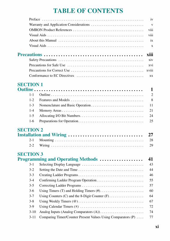
TABLE OF CONTENTS
Z234-01.book Page xi Tuesday, September 13, 2005 5:22 PM
Preface . . . . . . . . . . . . . . . . . . . . . . . . . . . . . . . . . . . . . . . . . . . . . . . . . . . . . . . . iv
Warranty and Application Considerations . . . . . . . . . . . . . . . . . . . . . . . . . . . . . v
OMRON Product References . . . . . . . . . . . . . . . . . . . . . . . . . . . . . . . . . . . . . . . viii
Visual Aids . . . . . . . . . . . . . . . . . . . . . . . . . . . . . . . . . . . . . . . . . . . . . . . . . . . . . viii
About this Manual . . . . . . . . . . . . . . . . . . . . . . . . . . . . . . . . . . . . . . . . . . . . . . . ix
Visual Aids . . . . . . . . . . . . . . . . . . . . . . . . . . . . . . . . . . . . . . . . . . . . . . . . . . . . . x
Precautions . . . . . . . . . . . . . . . . . . . . . . . . . . . . . . . . . . . . . . . . . xiiiSafety Precautions . . . . . . . . . . . . . . . . . . . . . . . . . . . . . . . . . . . . . . . . . . . . . . . xiv
Precautions for Safe Use . . . . . . . . . . . . . . . . . . . . . . . . . . . . . . . . . . . . . . . . . . xvi
Precautions for Correct Use . . . . . . . . . . . . . . . . . . . . . . . . . . . . . . . . . . . . . . . . xviii
Conformance to EC Directives . . . . . . . . . . . . . . . . . . . . . . . . . . . . . . . . . . . . . xx
SECTION 1Outline . . . . . . . . . . . . . . . . . . . . . . . . . . . . . . . . . . . . . . . . . . . . . 1
1-1 Outline . . . . . . . . . . . . . . . . . . . . . . . . . . . . . . . . . . . . . . . . . . . . . . . . . . . 2
1-2 Features and Models . . . . . . . . . . . . . . . . . . . . . . . . . . . . . . . . . . . . . . . . 8
1-3 Nomenclature and Basic Operation . . . . . . . . . . . . . . . . . . . . . . . . . . . . . 11
1-4 Memory Areas . . . . . . . . . . . . . . . . . . . . . . . . . . . . . . . . . . . . . . . . . . . . . 21
1-5 Allocating I/O Bit Numbers. . . . . . . . . . . . . . . . . . . . . . . . . . . . . . . . . . . 24
1-6 Preparations for Operation. . . . . . . . . . . . . . . . . . . . . . . . . . . . . . . . . . . . 25
SECTION 2Installation and Wiring . . . . . . . . . . . . . . . . . . . . . . . . . . . . . . . 27
2-1 Mounting . . . . . . . . . . . . . . . . . . . . . . . . . . . . . . . . . . . . . . . . . . . . . . . . . 28
2-2 Wiring . . . . . . . . . . . . . . . . . . . . . . . . . . . . . . . . . . . . . . . . . . . . . . . . . . . 29
SECTION 3Programming and Operating Methods . . . . . . . . . . . . . . . . . . 41
3-1 Selecting Display Language . . . . . . . . . . . . . . . . . . . . . . . . . . . . . . . . . . 43
3-2 Setting the Date and Time . . . . . . . . . . . . . . . . . . . . . . . . . . . . . . . . . . . . 44
3-3 Creating Ladder Programs . . . . . . . . . . . . . . . . . . . . . . . . . . . . . . . . . . . . 46
3-4 Confirming Ladder Program Operation. . . . . . . . . . . . . . . . . . . . . . . . . . 55
3-5 Correcting Ladder Programs . . . . . . . . . . . . . . . . . . . . . . . . . . . . . . . . . . 57
3-6 Using Timers (T) and Holding Timers (#) . . . . . . . . . . . . . . . . . . . . . . . . 60
3-7 Using Counters (C) and the 8-Digit Counter (F) . . . . . . . . . . . . . . . . . . . 64
3-8 Using Weekly Timers (@) . . . . . . . . . . . . . . . . . . . . . . . . . . . . . . . . . . . . 67
3-9 Using Calendar Timers (*) . . . . . . . . . . . . . . . . . . . . . . . . . . . . . . . . . . . 72
3-10 Analog Inputs (Analog Comparators (A)) . . . . . . . . . . . . . . . . . . . . . . . . 74
3-11 Comparing Timer/Counter Present Values Using Comparators (P) . . . . 77
xi

TABLE OF CONTENTS
Z234-01.book Page xii Tuesday, September 13, 2005 5:22 PM
3-12 Comparing the 8-Digit Counter (F) Present Value Using 8-Digit Comparators (G). . . . . . . . . . . . . . . . . . . . . . . . . . . . . . . . . . . . . . . . . . . . 80
3-13 Displaying Messages (Display Bits (D)) . . . . . . . . . . . . . . . . . . . . . . . . . 82
3-14 Using Button Input Bits (B) . . . . . . . . . . . . . . . . . . . . . . . . . . . . . . . . . . . 85
SECTION 4Special Functions. . . . . . . . . . . . . . . . . . . . . . . . . . . . . . . . . . . . . 87
4-1 Protecting Programs . . . . . . . . . . . . . . . . . . . . . . . . . . . . . . . . . . . . . . . . . 88
4-2 Stabilizing Input Operations. . . . . . . . . . . . . . . . . . . . . . . . . . . . . . . . . . . 90
4-3 Changing Backlight Automatic Cutout Time. . . . . . . . . . . . . . . . . . . . . . 92
4-4 Setting Daylight Saving Time (DST) . . . . . . . . . . . . . . . . . . . . . . . . . . . . 93
4-5 Reading System Information . . . . . . . . . . . . . . . . . . . . . . . . . . . . . . . . . . 94
SECTION 5Optional Products . . . . . . . . . . . . . . . . . . . . . . . . . . . . . . . . . . . . 95
5-1 Mounting Battery Units . . . . . . . . . . . . . . . . . . . . . . . . . . . . . . . . . . . . . . 96
5-2 Using Memory Cassettes . . . . . . . . . . . . . . . . . . . . . . . . . . . . . . . . . . . . . 97
5-3 Connecting the ZEN Support Software . . . . . . . . . . . . . . . . . . . . . . . . . . 99
SECTION 6Troubleshooting. . . . . . . . . . . . . . . . . . . . . . . . . . . . . . . . . . . . . . 101
6-1 Troubleshooting . . . . . . . . . . . . . . . . . . . . . . . . . . . . . . . . . . . . . . . . . . . . 102
6-2 Error Messages. . . . . . . . . . . . . . . . . . . . . . . . . . . . . . . . . . . . . . . . . . . . . 102
6-3 Deleting Error Messages . . . . . . . . . . . . . . . . . . . . . . . . . . . . . . . . . . . . . 104
AppendicesA Specifications . . . . . . . . . . . . . . . . . . . . . . . . . . . . . . . . . . . . . . . . . . . . . 105
B Ladder Program Execution . . . . . . . . . . . . . . . . . . . . . . . . . . . . . . . . . . . 113
C Operating Mode at Startup . . . . . . . . . . . . . . . . . . . . . . . . . . . . . . . . . . . 117
D Version Upgrades . . . . . . . . . . . . . . . . . . . . . . . . . . . . . . . . . . . . . . . . . . 119
E Application Examples . . . . . . . . . . . . . . . . . . . . . . . . . . . . . . . . . . . . . . . 125
F Allocations and Setting Table . . . . . . . . . . . . . . . . . . . . . . . . . . . . . . . . . 139
Index . . . . . . . . . . . . . . . . . . . . . . . . . . . . . . . . . . . . . . . . . . . . . . . 145
Revision History . . . . . . . . . . . . . . . . . . . . . . . . . . . . . . . . . . . . . 149
xii
Z234-01.book Page xiii Tuesday, September 13, 2005 5:22 PM
Precautions
This section provides precautions for using the ZEN Programmable Relays.
This information contained in this section is important for the safe and reliable application of the ZEN. You must read this section and understand the information before attempting to set up for a ZEN.
Safety Precautions. . . . . . . . . . . . . . . . . . . . . . . . . . . . . . . . . . . . . . . . . . . . . . . . . . xiv
Precautions for Safe Use . . . . . . . . . . . . . . . . . . . . . . . . . . . . . . . . . . . . . . . . . . . . . xvi
Precautions for Correct Use . . . . . . . . . . . . . . . . . . . . . . . . . . . . . . . . . . . . . . . . . xviii
Conformance to EC Directives . . . . . . . . . . . . . . . . . . . . . . . . . . . . . . . . . . . . . . . . . xx
xiii

Precautions
Z234-01.book Page xiv Tuesday, September 13, 2005 5:22 PM
Definition of Precautionary Information
The following notation is used in this manual to provide precautions required to ensure safe usage of the product.
The safety precautions that are provided are extremely important to safety. Always read and heed the information provided in all safety precautions.
The following notation is used.
Symbols
Safety Precautions
WARNING
Indicates a potentially hazardous situation which, if not avoided, will result in minor or moderate injury, or may result in serious injury or death. Additionally, there may be significant property damage.
CAUTIONIndicates a potentially hazardous situation which, if not avoided, may result in minor or moderate injury or in property damage.
Symbol Meaning
Caution
General Caution Indicates non-specific general cautions, warnings, and dangers.
Electrical Shock CautionIndicates possibility of electric shock under specific conditions.
Explosion CautionIndicates possibility of explosion under specific conditions.
Prohibition
Disassembly ProhibitionIndicates prohibitions when there is a possibility of injury, such as from electric shock, as the result of disassembly.
Mandatory Caution
General CautionIndicates non-specific general cautions, warnings, and dangers.
xiv

Precautions
Z234-01.book Page xv Tuesday, September 13, 2005 5:22 PM
Precautions
WARNING
Serious human hazard may occasionally occur due to ignition or rupture of the lithium battery used in the Battery Unit. Do not short the battery terminals or charge, disassemble, deform under pressure, or incinerate the battery.Never use any battery that has been dropped on the floor or otherwisesubjected to excessive shock.
CAUTION
Electric shock, fire, or malfunction may occur. Do not disassemble, modify, or repair the ZEN or touch any of the internal parts.
Electrical shock may occur. Never touch the I/O terminals, computer connector, or Battery Unit connector while power is being supplied.
Electrical shock may occur. Do not remove the Expansion Unit connector cover.
Fires may occasionally occur. Tighten the terminal block screws to the specified torque (0.5 to 0.6 N·m) so that they do not become loose.
xv
Precautions
Z234-01.book Page xvi Tuesday, September 13, 2005 5:22 PM
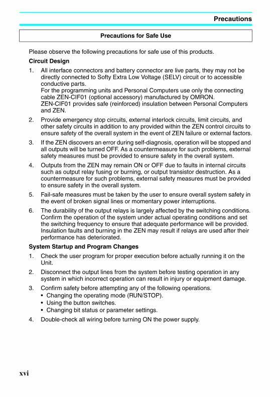
Please observe the following precautions for safe use of this products.
Circuit Design
1. All interface connectors and battery connector are live parts, they may not be directly connected to Softy Extra Low Voltage (SELV) circuit or to accessible conductive parts.For the programming units and Personal Computers use only the connecting cable ZEN-CIF01 (optional accessory) manufactured by OMRON.ZEN-CIF01 provides safe (reinforced) insulation between Personal Computers and ZEN.
2. Provide emergency stop circuits, external interlock circuits, limit circuits, and other safety circuits in addition to any provided within the ZEN control circuits to ensure safety of the overall system in the event of ZEN failure or external factors.
3. If the ZEN discovers an error during self-diagnosis, operation will be stopped and all outputs will be turned OFF. As a countermeasure for such problems, external safety measures must be provided to ensure safety in the overall system.
4. Outputs from the ZEN may remain ON or OFF due to faults in internal circuits such as output relay fusing or burning, or output transistor destruction. As a countermeasure for such problems, external safety measures must be provided to ensure safety in the overall system.
5. Fail-safe measures must be taken by the user to ensure overall system safety in the event of broken signal lines or momentary power interruptions.
6. The durability of the output relays is largely affected by the switching conditions. Confirm the operation of the system under actual operating conditions and set the switching frequency to ensure that adequate performance will be provided. Insulation faults and burning in the ZEN may result if relays are used after their performance has deteriorated.
System Startup and Program Changes
1. Check the user program for proper execution before actually running it on the Unit.
2. Disconnect the output lines from the system before testing operation in any system in which incorrect operation can result in injury or equipment damage.
3. Confirm safety before attempting any of the following operations.• Changing the operating mode (RUN/STOP).• Using the button switches.• Changing bit status or parameter settings.
4. Double-check all wiring before turning ON the power supply.
Precautions for Safe Use
xvi

Precautions
Z234-01.book Page xvii Tuesday, September 13, 2005 5:22 PM
Installation and Wiring
1. Do not allow the ZEN to fall during installation.
2. Be sure that the DIN Track mounting levers, Memory Cassettes, Battery Units, cable connectors, and other items with locking devices are properly locked into place. Improper locking may result in malfunction.
3. Tighten mounting screws to the following torques.CPU Units: 1.03 N⋅m max.
4. Use wires with cross-sectional areas of 0.2 to 2.5 mm2 (equivalent to AWG24 to AWG14) for wiring and strip them for 6.5 mm. If using stranded wires, always connect straight crimp terminals (0.25 to 2.5 mm2).
Handling
1. The environment of use of ZEN is "Pollution degree 2" and "Overvoltage category II" specified in IEC60664-1.
2. Always use the ZEN within the rated ambient operating temperature and humidity. The rated ambient operating temperature is 0 to 55°C. If the ZEN is used near sources of heat, such as a power supply, the internal temperature of the ZEN may increase, lowering the durability of the ZEN.
3. Discharge static electricity from your body, e.g., by touching a grounded metal plate, before touching any Unit.
4. The exterior of the Units will be damaged if it comes into contact with organic solvents (e.g., benzene or paint thinner), strong alkalies, or strong acids. Never allow such substances to come into contact with the Units.
5. Do not apply voltages exceeding the rated voltages. Internal elements may be destroyed.
6. Short failures or open failures may result from the destruction of output elements. Do not use loads that exceed the rated output current.
Maintenance
When replacing a CPU Unit, transfer to the new Unit and confirm all settings for clock data, internal holding bits, holding timers, and counters before starting operation again.
Transportation and Storage
1. Use special packaging boxes when transporting the ZEN and do not subject it to excessive shock or vibration or drop it during shipment.
2. Store the ZEN in within the rated ranges. If the ZEN has been stored at −10°C or lower, allow it to stand at room temperature for 3 hours or longer before turning ON the power supply.
xvii

Precautions
Z234-01.book Page xviii Tuesday, September 13, 2005 5:22 PM
Installation Environment
1. Do not install the ZEN in the following locations. • Locations subject to radical changes in temperature• Location with high humidity subject to condensation• Locations subject to excessive dust or dirt• Locations subject to corrosive gas• Locations subject to direct sunlight
2. Do not install the ZEN in locations subject to shock or vibration. Extended use in such location may cause damage from stress.
3. In environments subject to static electricity (e.g., close to pipes conveying forming materials, powders, or fluid materials), separate the ZEN as far as possible from the source of static electricity.
4. The ZEN is neither waterproof nor oil-proof. Do not use it in locations subject to water or oil.
5. Use the ZEN within the allowable power supply voltage range. Be particularly careful in locations with bad power supply conditions, e.g., large fluctuations in the power supply voltage.
6. Do not install the ZEN in locations subject to excessive noise, which may cause the ZEN to fail.
7. Take appropriate and sufficient countermeasures when installing systems in the following locations:• Locations subject to strong electromagnetic fields• Locations subject to possible exposure to radioactivity
Power Supply
1. Always turn OFF the power supply to the ZEN before attempting any of the following.
• Assembling the ZEN• Connecting or disconnecting any cables or wiring• Attaching or removing the Memory Cassette• Attaching or removing the Battery Unit
2. If the power supply is interrupted for 2 days or more (at 25°C), the internal capacitor will discharge and internal bit status and the contents of PV areas will be lost or corrupted and dates and times will be reset. When restarting operation after the power supply has been interrupted for an extended period of time, check the system in advance to confirm that no errors will occur.
Handling
1. Connect connectors only after confirming that the direction or polarity is correct.
2. Failures could result if dust or dirt enters the ZEN. Always connect the connector cover to the computer connector whenever it is not being used.
Precautions for Correct Use
xviii

Precautions
Z234-01.book Page xix Tuesday, September 13, 2005 5:22 PM
3. Do not remove the label from the left side of the CPU Unit if a Battery Unit is not mounted.
Other
1. The execution of the ladder program in the ZEN is different from that for other PLCs. Refer to Appendix B Ladder Program Execution when writing the ladder program.
2. Abide by all local ordinances and regulations when disposing of the ZEN.
xix

Precautions
Z234-01.book Page xx Tuesday, September 13, 2005 5:22 PM
Conformance to EC Directives
Applicable Directives• EMC Directives• Low Voltage Directive
ConceptsEMC DirectivesOMRON devices that comply with EC Directives also conform to the related EMC standards so that they can be more easily built into other devices or the overall machine. The actual products have been checked for conformity to EMC standards. The ZEN complies with IEC/EN61131-2 clause 8. Whether the products conform to the standards in the system used by the customer, however, must be checked by the customer.
EMC-related performance of the OMRON devices that comply with EC Directives will vary depending on the configuration, wiring, and other conditions of the equipment or control panel on which the OMRON devices are installed. The customer must, therefore, perform the final check to confirm that devices and the overall machine conform to EMC standards.
Low Voltage DirectiveAlways ensure that devices operating at voltages of 50 to 1,000 VAC and 75 to 1,500 VDC meet the required safety standards. The ZEN complies with IEC/EN61131-2 clause 11.
Conformance to EC DirectivesThe ZEN complies with EC Directives. To ensure that the machine or device in which the ZEN is used complies with EC Directives, the ZEN must be installed as follows:
1. The ZEN is an open-structure device and it must be installed within a control panel.2. You must use reinforced insulation or double insulation for the DC power supplies
used for the communications power supply and I/O power supplies.3. ZEN models complying with EC Directives also conform to the Common Emission
Standard (IEC/EN61131-2 clause 8). Radiated emission characteristics (10-m regulations) may vary depending on the configuration of the control panel used, other devices connected to the control panel, wiring, and other conditions. You must therefore confirm that the overall machine or equipment complies with EC Directives.
xx

Precautions
Z234-01.book Page xxi Tuesday, September 13, 2005 5:22 PM
Relay Output Noise Reduction MethodsThe ZEN conforms to EN 61131-2 of the EMC Directives. However, noise generated by relay output switching may not satisfy these Standards. In such a case, a noise filter must be connected to the load side or other appropriate countermeasures must be provided external to the ZEN.Countermeasures taken to satisfy the standards vary depending on the devices on the load side, wiring, configuration of machines, etc. Following are examples of countermeasures for reducing the generated noise.
Countermeasures(Refer to EN61131-2 for more details.)
• Countermeasures are not required if the frequency of load switching for the whole system with the ZEN included is less than 5 times per minute.
• Countermeasures are required if the frequency of load switching for the whole system with the ZEN included is 5 times per minute or higher.
Countermeasure ExamplesWhen switching an inductive load, connect an surge protector, diodes,etc., in parallel with the load or contact as shown below.
Circuit Current Characteristic Required element
AC DC
CR method Yes Yes If the load is a relay or solenoid, there is a time lag between the moment the circuit is opened and the moment the load is reset.
If the supply voltage is 12 to 48 V, insert the surge protector in parallel with the load. If the supply voltage is 100 to 200 V, insert the surge protector between the contacts.
The capacitance of the capacitor must be 1 to 0.5 µF per contact current of 1 A and resistance of the resistor must be 0.5 to 1 Ω per contact voltage of 1 V. These values, however, vary with the load and the characteristics of the relay. Decide these values from experiments, and take into consideration that the capacitance suppresses spark discharge when the contacts are separated and the resistance limits the current that flows into the load when the circuit is closed again.
The dielectric strength of the capacitor must be 200 to 300 V. If the circuit is an AC circuit, use a capacitor with no polarity.
Powersupply
Indu
ctiv
elo
ad
C
R
xxi

Precautions
Z234-01.book Page xxii Tuesday, September 13, 2005 5:22 PM
Diode method No Yes The diode connected in parallel with the load changes energy accumulated by the coil into a current, which then flows into the coil so that the current will be converted into Joule heat by the resistance of the inductive load.
This time lag, between the moment the circuit is opened and the moment the load is reset, caused by this method is longer than that caused by the CR method.
The reversed dielectric strength value of the diode must be at least 10 times as large as the circuit voltage value. The forward current of the diode must be the same as or larger than the load current.
The reversed dielectric strength value of the diode may be two to three times larger than the supply voltage if the surge protector is applied to electronic circuits with low circuit voltages.
Varistor method Yes Yes The varistor method prevents the imposition of high voltage between the contacts by using the constant voltage characteristic of the varistor. There is time lag between the moment the circuit is opened and the moment the load is reset.
If the supply voltage is 12 to 48 V, insert the varistor in parallel with the load. If the supply voltage is 100 to 200 V, insert the varistor between the contacts.
---
Circuit Current Characteristic Required element
AC DC
Powersupply
Indu
ctiv
elo
ad
Powersupply
Indu
ctiv
elo
ad
xxii

Z234-01.book Page 1 Tuesday, September 13, 2005 5:22 PM
SECTION 1Outline
This section gives an outline of the ZEN, including example applications, the system configurations and basic operations.
1-1 Outline . . . . . . . . . . . . . . . . . . . . . . . . . . . . . . . . . . . . . . . . . . . . . . . . . . . . . . 2
1-2 Features and Models . . . . . . . . . . . . . . . . . . . . . . . . . . . . . . . . . . . . . . . . . . . 8
1-2-1 Features and System Configuration . . . . . . . . . . . . . . . . . . . . . . . . 8
1-2-2 List of Models . . . . . . . . . . . . . . . . . . . . . . . . . . . . . . . . . . . . . . . . 9
1-3 Nomenclature and Basic Operation . . . . . . . . . . . . . . . . . . . . . . . . . . . . . . . . 11
1-3-1 Nomenclature. . . . . . . . . . . . . . . . . . . . . . . . . . . . . . . . . . . . . . . . . 11
1-3-2 Screen Transitions . . . . . . . . . . . . . . . . . . . . . . . . . . . . . . . . . . . . . 13
1-3-3 Basic Operation . . . . . . . . . . . . . . . . . . . . . . . . . . . . . . . . . . . . . . . 16
1-4 Memory Areas . . . . . . . . . . . . . . . . . . . . . . . . . . . . . . . . . . . . . . . . . . . . . . . . 21
1-5 Allocating I/O Bit Numbers. . . . . . . . . . . . . . . . . . . . . . . . . . . . . . . . . . . . . . 24
1-6 Preparations for Operation. . . . . . . . . . . . . . . . . . . . . . . . . . . . . . . . . . . . . . . 25
1

Outline Section 1-1
Z234-01.book Page 2 Tuesday, September 13, 2005 5:22 PM
1-1 Outline
Economical, Small-scale Automatic ControlOne CPU Unit provides 6 inputs and 4 outputs.
Easy Operation with an Inexpensive ControllerLadder programming is possible directly from the CPU Unit. With Memory Cassettes (optional), ladder programs can be easily copied.
Smaller Control PanelsThe ZEN is very small at 90 x 70 x 56 mm (H x W x D) and mounts essentially anywhere.
Less Assembly and Wiring Time Required for Control PanelsSimple one-touch DIN Track mounting. Built-in timers and counters so only power supply and I/O circuit wiring required.
Solid wires can be easily connected using only a screwdriver.
Refer to page 29.
3
Water-supply facilities in apartments, lighting control in offices.
3
3
70 mm
90 mm
3
2

Outline Section 1-1
Z234-01.book Page 3 Tuesday, September 13, 2005 5:22 PM
Power Failure CountermeasuresEEPROM backs up the program and system settings data when no power is supplied to the ZEN.
Use a Battery Unit (optional) to back up work bits, holding timers, counters, and date/time data.
Refer to page 96.
Easy Saving and Copying of ProgramsUse an optional Memory Cassette to easily save and copy programs.
Refer to page 97.
Programming and Monitoring from a Personal ComputerWindows-based ZEN Support Software is available and provides a complete simulation function.
Refer to page 99.
3
Battery Unit
3
Ladder program data/settings.
Memory Cassette
3
ZEN Support Software(CD-ROM)
3

Outline Section 1-1
Z234-01.book Page 4 Tuesday, September 13, 2005 5:22 PM
Greater Switching CapacityThe output contacts have 8-A switching capacity (250 VAC). All contacts are independent.
Refer to page 38.
AC InputsFor CPU Units with AC power supply inputs, 100 to 240 VAC can be directly connected.
Refer to page 32.
Easy Program DesignThere are 3 different operations that can be set for bit outputs. Self-holding bits also can be easily programmed.
Refer to page 50.
Complicated Timers without Additional ProgrammingAny of the 16 timers support 5 types of operation and 3 timing ranges.
There are also 8 built-in holding timers that hold data during power interruptions.
8 A max.
MC
250 V
L N NC I0 I1 I2 I3 I4 I5
Circuit protector
100 to 240 VACL N
Ry
Normal operationSet/reset operationAlternate operation
4

Outline Section 1-1
Z234-01.book Page 5 Tuesday, September 13, 2005 5:22 PM
Refer to page 60.
Incremental and Decremental CountersThere are 16 built-in counters that can be switched between incrementing and decrementing.
Use Comparators to enable programming multiple outputs from a counter.
Counters: Refer to page 64.
Comparators: Refer to page 77.
Season- or Day-dependent Operating TimesCPU Units with built-in calendar and clock functions have 16 weekly timers and 16 calendar timers. Seasonal control is possible using calendar timers and day/time control is possible with weekly timers.
Weekly timers: Refer to page 67.
Calendar timers: Refer to page 72.
Direct Analog InputsCPU Units with DC power supply inputs have 2 analog input points (0 to 10 V) and 4 analog comparators.
TIM
ON delayOFF delayOne-shot pulseFlashing pulseTwin timer
0.01 to 99.99 s
1 s to 99 min 59 s
1 min to 99 h 59 min
C
D
R
CNT
Control number of cars entering and leaving a car park.
MO FR−
SA SU−
For gardens, parks, and recreational ponds.
5

Outline Section 1-1
Z234-01.book Page 6 Tuesday, September 13, 2005 5:22 PM
Refer to page 74.
Easier MaintenanceUse the display function in CPU Units to display user-specified messages, the date, time, or other data. Button switches can also be used as input contacts. Applications include usage as a simple display operation panel.
Refer to page 82.
Longer Backlight for Dark SituationsThe automatic cutout time for the backlight for CPU Units can be set to 2, 10, or 30 minutes, or set to operate continuously. With the display function, the backlight can also be set to turn ON when a message is displayed.
Refer to page 92.
Temperature control for hot houses and tanks. Prevent freezing of swimming pools.
3
6

Outline Section 1-1
Z234-01.book Page 7 Tuesday, September 13, 2005 5:22 PM
Prevent Chattering and Noise-related MalfunctionsSet the input filters to extend the filter timer and prevent malfunctions.
Refer to page 90.
Exporting Systems OverseasDisplay for CPU Units is available in 6 languages. A Daylight Saving Time (DST) function also supported.
Changing display language: Refer to page 43.
Daylight Saving Time (DST) settings: Refer to page 93.
Programming SecurityPrograms can be protected by setting a password.
Refer to page 88.
Filter timerON
3
ENGLISHJAPANESEGERMANFRENCHITALIANSPANISH
3 9 5 4
PASSWORD
0000
RUN
7

Features and Models Section 1-2
Z234-01.book Page 8 Tuesday, September 13, 2005 5:22 PM
1-2 Features and Models
1-2-1 Features and System ConfigurationThe ZEN is small but has a wide range of functions and is easy to use. The ZEN facilitates small-scale automatic control.
• Simple button-operated programming.
• Highly visible, backlit LCD.
• Adjustable automatic cutout time for the backlight.
• Six-language display.
• Display function for user-specified messages (4 lines x 12 characters), time, or timer, counter, or analog-converted value displays.
• Button switches allowing operation buttons to be used as input contacts.
• Built-in weekly and calendar timers to allow simple seasonal, daily, or time-based operation.
• Both 100 to 240-VAC and 12 to 24-VDC power supply models available.
• Built-in analog comparator for temperature control and other analog applications (provided on CPU Units with DC power supply inputs, two analog inputs 0 to 10 V).
• Input filter settings to prevent noise-related malfunctions for CPU Units.
• Program and settings data backed up on built-in EEPROM.
• Programming using ladder diagrams.
• Password function to protect programs.
8

Features and Models Section 1-2
Z234-01.book Page 9 Tuesday, September 13, 2005 5:22 PM
1-2-2 List of Models
CPU Units with 10 I/O Points
Note Refer to Input Specifications on page 108 for input specifications.
Shape Power supply/ input
voltage
Inputs Outputs Analog inputs
Model number
With display and operation buttons
Economy type (Expansion I/O Units cannot be connected)
100 to 240 VAC, 50/60 Hz
6 inputs Relays 4 outputs No ZEN-10C3AR-A-V2
12 to 24 VDC Yes ZEN-10C3DR-D-V2
3
CPU Unit
ZEN-BAT01 Battery Unit
Programs can be saved and copied by using a Memory Cassette (optional).
Personal computer connecting cable
ZEN-SOFT01-V4ZEN Support Software
Programs can be created, edited, saved, and printed, and operation can be simulated using the ZEN Support Software (optional).
ZEN-ME01 Memory Cassette
Work bits, holding timer data, counter data, and date/time data will be backed up during long-term power supply interruptions if a Battery Unit (optional) is mounted.
3
9

Features and Models Section 1-2
Z234-01.book Page 10 Tuesday, September 13, 2005 5:22 PM
Power Supply Unit
Programming Device
Optional Products
Name and appearance Specifications Model number
Switching Power supply Unit
Input voltage: 100 to 240 VACOutput voltage: 24 VDCOutput capacity: 1.3 ACapacity: 30 W
ZEN-PA03024
Name and appearance Functions Model number
ZEN Support Software Runs on Windows 95, 98, ME, 2000, XP, or NT4.0 Service Pack 3 (CD-ROM)
Used for offline programming, all parameter settings, program transfers, and printing.
ZEN-SOFT01-V4
Personal Computer Connecting Cable
Connects the computer and ZEN when the ZEN Support Software is used.(Cable length: 2 m)
ZEN-CIF01
Name and appearance
Functions Model number
Memory Cassette EEP-ROM
Used to save and copy programs.
ZEN-ME01
Battery Unit Uses a battery to back up programs and data.
Mount a Battery Unit if the loss of calendar, clock, holding bit, holding timer, and counter present values will cause problems in systems with long power interruptions. (Battery life: 10 years minimum)
ZEN-BAT01
10

Nomenclature and Basic Operation Section 1-3
Z234-01.book Page 11 Tuesday, September 13, 2005 5:22 PM
1-3 Nomenclature and Basic Operation
1-3-1 Nomenclature
Note Economy-type CPU Units do not have an Expansion Unit connector. Do not remove the Expansion Unit connector cover on these CPU Units.
Display Screen and Operation Buttons
Icon Meanings
3
Left Side
Battery Unit connector (Remove the seal to connect the Battery Unit.)
FrontPower supply terminals Input terminals
LCD Operation buttons
Output terminalsZEN Support Software connector (also used for Memory Cassette.)
Right Side
Expansion Unit connector cover. (See note.)
ZEN Support Software connector (also used for Memory Cassette.)
3
LCD ALT ButtonDEL Button
Cursor Buttons
ESC Button OK Button
RUN ERR
Icon Meaning
RUN Displayed while in RUN mode.
ERR Indicates an error.
11

Nomenclature and Basic Operation Section 1-3
Z234-01.book Page 12 Tuesday, September 13, 2005 5:22 PM
Operation Button Names and Operations
Displayed when there is a higher-level menu or ladder program line than the one currently displayed.
Displayed when there is a lower-level menu or ladder program line than the one currently displayed.
Displayed when a password has been set.
Button Function
Menus Writing ladder program Setting parameters Button switch (See page 85.)
DEL
--- Deletes inputs, outputs, connection lines, and blank lines.
--- B6 ON
ALT
--- Switches between normally open and normally closed conditions.
Changes to connection line write mode.
Inserts a line.
--- B7 ON
Up
Moves the cursor up and down.
Moves the cursor up and down.
Selects bit types and functions.
Moves the cursor up and down.
Changes numerals and parameters.
B5 ON
Down
B2 ON
Left
--- Moves the cursor right and left.
Moves the cursor right and left.
B3 ON
Right
B4 ON
ESC
Returns to the previous screen.
Cancels the setting and returns to the previous operation.
Cancels the setting and returns to the previous operation.
B0 ON
OK
Selects the menu item at the cursor position.
Confirms the setting. Confirms the setting. B1 ON
Icon Meaning
12

Nomenclature and Basic Operation Section 1-3
Z234-01.book Page 13 Tuesday, September 13, 2005 5:22 PM
1-3-2 Screen Transitions
Display ScreensMain Screen
STOP ModeWhen power is turned ON
Display Function Screen
Note: The display will be blank if the display function is not being used.
(User-specified message)
RUN ModeWhen power is turned ON
Display Function Screen
Note: The display will be blank if the display function is not being used.
(User-specified message)
STOP Mode
PROGRAM
RUN
PARAMETER
SET CLOCK
PARAMETER
SET CLOCK
LANGUAGE
OTHER
RUN Mode
MONITOR
STOP
PARAMETER
SET CLOCK
RUN
PARAMETER
SET CLOCK
LANGUAGE
OTHER
RUN
RUN
RUN
I0 I1 I2 I3 I4 I5
( : OFF/: ON)
Q0 Q1 Q2 Q3@ @ @ @
DayTime (min:s)
Operating mode CPU input bit (I) status
CPU output bit (Q) status(@: OFF/: ON)
Day display
SU: SundayMO: MondayTU: TuesdayWE: WednesdayTH: ThursdayFR: FridaySA: Saturday
13

Nomenclature and Basic Operation Section 1-3
Z234-01.book Page 14 Tuesday, September 13, 2005 5:22 PM
Menu Screen Configuration
MONITORSTOPPARAMETERSET CLOCK
RUN Mode Ladder Monitor ScreenThe ON/OFF status of input bits can be checked by monitoring the ladder program.
Switches to STOP mode.The operation status of the timers, counters, and analog comparators can be monitored and the settings changed during operation. Refer to page 19.
STOP Mode Ladder Program Edit Screen (Refer to page 17.)
PROGRAMRUNPARAMETERSET CLOCK
EDIT PROGDELETE PROGCASSETTE
Creates and edits ladder program.
Deletes ladder program and parameters.Memory Cassette Operation (Refer to page 97.)
SAVE(CPU-MC)LOAD(MC-CPU)ERASE
Transfers programs between ZEN and the Memory Cassette and initializes the Memory Cassette.
Switches to RUN mode.Note: Displayed only when a Memory Cassette is mounted.
Changes the settings for timers, counters, and analog comparators. (Refer to page 22.)
Date and Time Settings (Refer to page 44.)PROGRAMRUNPARAMETERSET CLOCK
SET CLOCKSUMMER TIME
SET CLOCKyy/mm/dd00/01/01 00:03(SA)
Sets the date and time.
Set when shipping to countries that use summer time. (Refer to page 93.)
Display Language Settings (Refer to page 43.)SET CLOCKLANGUAGE
LANGUAGE
ENGLISH
The display language can be changed.English, Japanese, German, French, Italian, and Spanish
EDIT PROGRAM NO YES
Other SettingsPARAMETERSET CLOCKLANGUAGEOTHER
PASSWORDBACKLIGHTINPUT FILTERSYSTEM INF
Other settings can be made. Refer to the following page for details.
Select YES with
RUNRUN
14

Nomenclature and Basic Operation Section 1-3
Z234-01.book Page 15 Tuesday, September 13, 2005 5:22 PM
Other SubmenusPASSWORDBACKLIGHTINPUT FILTERSYSTEM INF
PASSWORD
0000
Setting Passwords (Refer to page 88.)
Set a password when you want to protect programs from being read. The password setting range is 0000 to 9999.
BACKLIGHTINPUT FILTERSYSTEM INFMODEM INI
BACKLIGHT
2min
Changing Cutout Time for Backlight (Refer to page 92.)
Set the automatic cutout time for the backlight in the LCD screen.2 min, 10 min, 30 min, Always ON
INNEREXP1EXP2EXP3
Setting Input Filters (Refer to page 90.)
Set the input filters to ON or OFF for the CPU Unit or Expansion I/O Units. Set to ON when noise or chattering may affect operation.
U03.00050701INT:I06O04EX1:I00O00
Reading System Information (Refer to page 94.)
Read system information, such as the CPU Unit software version or the date it was created, the number of I/O points on the CPU Unit, and whether or not LCD, RTC, or analog input functions are supported.
EX2:I00O00EX3:I00O00RMT:I00000LCD:YES
RMT:I00000LCD:YESRTC:YESADC:YES
For future expansion. Do not set.
15

Nomenclature and Basic Operation Section 1-3
Z234-01.book Page 16 Tuesday, September 13, 2005 5:22 PM
1-3-3 Basic Operation
Menu Selection ExampleUse the Up/Down Buttons to move the cursor.
Press the OK Button to select the flashing menu. The settings will flash on a reversed display.
Settings cannot be changed during reversed display.
Press the OK Button to change from a highlighted cursor to a flashing cursor. Settings can now be changed.
Use the Up/Down Buttons to change the setting.
Use the Up Button to select GERMAN.
RUNPARAMETERSET CLOCKLANGUAGE
Main menu display
Flashing cursor
LANGUAGE
Highlighted cursor
ENGLISH
LANGUAGE
ENGLISH
Flashing cursor
LANGUAGE
GERMAN
LANGUAGE SET? OK/ESC GERMAN
A confirmation message will be displayed asking if you want to change to German display.
RUNPARAMETERKALENDERSPRACHE
Press the OK Button to change from English to German.
RUNPARAMETERSET CLOCKLANGUAGE
Press the ESC Button to cancel the change and return to the previous screen.
16

Nomenclature and Basic Operation Section 1-3
Z234-01.book Page 17 Tuesday, September 13, 2005 5:22 PM
Example Operation in the Ladder Program Edit ScreenThe highlighted cursor will appear in the initial write position. During highlighted cursor display, the cursor can be moved to the input or output write positions.
Up/Down Buttons: Move the highlighted cursor up and down.
Left/Right Buttons: Move the highlighted cursor Left/Right.
Press the OK Button at the input write position to display the input default setting IO and the normally open condition symbol. “I” will flash.
• Flashing Cursor at the I PositionUp/Down Buttons: Change the bit type.Right Button: Moves the flashing cursor to the right.OK Button: Sets the bit type and moves the flashing cursor to the bit address position.
• Flashing Cursor at the 0 PositionUp/Down Buttons: Change the bit address.OK Button: Completes the writing of the bit.
• Switching between Normally Open and Normally Closed ConditionsYou can use the ALT Button to switch between the N.O. and N.C. conditions, regardless of the position of the flashing cursor.
When the first input has been written, the highlighted cursor moves to the next input position.
Use the above procedure to enter program input conditions in series.
When writing serial inputs, the connecting line between inputs is drawn automatically.
Select Program/Edit.
Line No. at cursor
Highlighted cursor
17

Nomenclature and Basic Operation Section 1-3
Z234-01.book Page 18 Tuesday, September 13, 2005 5:22 PM
Press the ALT Button with the highlighted cursor in the input writing position to change the cursor to a flashing left arrow to enable connecting lines to be drawn.
Up/Down Buttons: Draw vertical connecting lines.
Left/Right Buttons: Draw horizontal connecting lines.
Press the Right Button twice to draw a line to the output bit. The cursor will change to a highlighted cursor at the output bit write position.
Press the OK Button at the output bit write position to display the default output Q0. Q will flash.
• Flashing Cursor at the Q (Bit Type) PositionUp/Down Buttons: Change the type of outputRight/Left Buttons: Move the flashing cursor.OK Button: Sets the bit type and moves the flashing cursor to the bit address position.
• Flashing Cursor at the (Additional Output Function) PositionUp/Down Buttons: Selects the additional output functionOK Button: Sets the additional output function and moves the flashing cursor to the bit address position.
• Flashing Cursor at the 0 (Bit Address) PositionUp/Down Buttons: Select the bit addressOK Button: Completes the output write.
Press the OK Button to complete the bit write and to move the highlighted cursor to the first input position ON the next line.
Press the ESC Button to complete the writing of the ladder program and to return to the menu screen.
01
18

Nomenclature and Basic Operation Section 1-3
Z234-01.book Page 19 Tuesday, September 13, 2005 5:22 PM
Example Parameter Settings Screen OperationWhen PARAMETER is selected, the settings for bits that are being used by the ladder program are displayed.
(1) Selecting Parameters to DisplayPress the OK Button to change the highlighted cursor to a flashing cursor.
Use the Up/Down Buttons to select another timer.
When multiple parameters of the same type have been selected, use the Up/Down Buttons to scroll through the numbers.
Press the Left Button to switch to another type, move the flashing cursor to the bit type position and use the Up/Down Buttons to select the bit type.
Move the flashing cursor to the bit type position and use the Up/Down Buttons to select another bit type.
(2) Setting and Changing Parameters
Use the Left/Right Buttons to move the highlighted cursor to the parameter to be set.
Press the OK Button to confirm the set position. The cursor will change to a flashing cursor.
Use the Up/Down Buttons to set the parameter.
Press the OK Button to confirm the setting.
Select Parameters on menu screen.
/
/
/
19

Nomenclature and Basic Operation Section 1-3
Z234-01.book Page 20 Tuesday, September 13, 2005 5:22 PM
Use the Left/Right or Up/Down Buttons to move the highlighted cursor to the parameter to be set.
Press the OK Button to confirm the set position. The cursor will change to a flashing cursor.
Use the Left/Right Buttons to select the digit to be set.
Use the Up/Down Buttons to change the value of each digit.
Press the OK Button to confirm the setting.
Press the ESC Button to complete the settings.
Note If the ESC Button is pressed while ladder program or parameter settings are being input, the input to that point will be canceled and the settings will return to the original settings.
20

Memory Areas Section 1-4
Z234-01.book Page 21 Tuesday, September 13, 2005 5:22 PM
1-4 Memory Areas
I/O, Work, and Internal Holding Bits
Note The following additional functions can be selected for bit outputs.
Name Type Bit addresses
No. of
bits
Function Ladder programs
Page
CPU Unit input bits
I 0 to 5 6 CPU Units with 10 I/O pts
Reflect the ON/OFF status of the input devices connected to the CPU Unit input terminals.
N.O./N.C. inputs
24
0 to b 12 CPU Units with 20 I/O pts
Button input bits
B 0 to 7 8 Turn ON when the operation buttons are pressed in RUN mode. Cannot be used for LED-type CPU Units.
85
Analog comparator bits
A 0 to 3 4 Output the comparison result for analog inputs. Can only be used for models with a 24-VDC power supply.
74
Compara-tor bits
P 0 to f 16 Compare the present value of timers (T), holding timers (#), and counters (C), and outputs the comparison result.
77
8-Digit comparator bits
G 0 to 3 4 Compare the present value of 8-digit counters (F) with a constant and outputs the comparison result
80
CPU Unit output bits
Q 0 to 3 4 CPU Units with 10 I/O pts
Output the ON/OFF status of the output bits to the outputs devices connected to the CPU Unit.
N.O./N.C. inputs
Outputs (See note.)
24
0 to 7 8 CPU Units with 20 I/O pts
0 to 2 3 CPU Units with Commu-nications
Work bits M 0 to f 16 Can only be used within the program. Cannot output to an external device.
-
Holding bits
H 0 to f 16 Same as for work bits however the holding bits maintain ON/OFF status when power is turned OFF.
-
Execution conditionBit address
Bit typeAdditional function ([, S, R, A)
21

Memory Areas Section 1-4
Z234-01.book Page 22 Tuesday, September 13, 2005 5:22 PM
Timers and Counters
Timer Types
Normal output [ Turns ON or OFF according to the ON/OFF status of the execution condition.
Set/Reset S (set) Holds ON status after the execution condition turns ON once.
R (reset) Holds OFF status after the execution condition turns ON once.
Alternate A Alternates between ON and OFF whenever the execution condition turns ON (input latch operation).
Name Type Bit ad-dresses
No. of timers/
counters
Function Use in ladder
programs
Page
Timer T 0 to f 16 Can be switched between ON delay, OFF delay, one-shot, flashing pulse, and twin timer operation.(See note.)
N.O./N.C. condition
60
Holding timer
# 0 to 7 8 Hold the present value during counting even if the trigger input or power supply is turned OFF. Continues the timing when the trigger input or power supply is turned ON again.
60
Counter C 0 to f 16 Four-digit reversible counters that can be incremented and decremented.
64
8-Digit counter
F 0 1 An eight-digit reversible counter that can be incremented and decremented. CPU Units with DC power supplies support a high-speed counter up to 150 Hz.
64
Weekly timer
@ 0 to f 16 Can be switched between normal operation, operation between days, and pulse output operation.
67
Calendar timer
0 to f 16 Can turn ON or OFF during a specified date period.
72
X ON delay Times down while the trigger input is ON and turns ON the timer bit when the set time is reached.
OFF delay
Turns ON the timer bit while the trigger input is ON, starts timing down when the trigger input turns OFF, and turns OFF the timer bit when the set time is reached.
O One-shot Turns ON the timer bit for the set period when the trigger input changes from OFF to ON only.
F Flashing pulse
Timer bit repeatedly turns ON/OFF at set intervals while the trigger input is ON.
W Twin Timer bit repeatedly turns ON/OFF at set intervals while the trigger input is ON. The ON time and OFF time can be set separately.
22

Memory Areas Section 1-4
Z234-01.book Page 23 Tuesday, September 13, 2005 5:22 PM
Display Bits
Function switching
Name Type Bit addresses
No. of
bits
Function Use in ladder
programs
Page
Display D 0 to f 16 Display user-specified character strings, times, timer present values, counter present values, or analog-converted values.
Output 82
D Display
C Clear display
D Display No.
Function switching
23

Allocating I/O Bit Numbers Section 1-5
Z234-01.book Page 24 Tuesday, September 13, 2005 5:22 PM
1-5 Allocating I/O Bit NumbersThe input bit addresses I0 to I5 and output bit addresses Q0 to Q3 are always allocated to the CPU Unit.
CPU Units with 10 I/O Points
Input bit address
CPU Unit (10 I/O points)
Output bit address
I0 I1 I2 I3 I4 I5
IN 0
IN 1
IN 2
IN 3
IN 4
IN 5
OUT 0
OUT 1
OUT 2
OUT 3
Q0 Q1 Q2 Q3
24

Preparations for Operation Section 1-6
Z234-01.book Page 25 Tuesday, September 13, 2005 5:22 PM
1-6 Preparations for Operation
3
3
3
3
Mount ZEN to Control PanelsThe ZEN can be mounted to either a DIN Track or directly onto the surface of the control panel. Refer to page 28.
Connect Power Supply, Input, and Output DevicesWire the ZEN to the power supply, input, and output devices. Refer to page 29.
Make Initial SettingsMake the settings required before programming, such as date, time, and display language. Refer to pages 43 and 44.
Write ProgramInput the ladder program, including timers, counters, and other parameters.Use the ZEN Support Software when using the LED-type CPU Units (without LCD.) Refer to page 46.
Check Program ExecutionPerform trial operation before starting actual operation and check that the system is operating correctly. Refer to page 55.
Save ProgramDebugged programs and all parameters should be saved to a Memory Cassette or ZEN Support Software to prevent loss of the data. Refer to page 97.
Actual Operation
DIN Track
InputsPower supply
Output
Load
Load
Load
Load
Operation buttons
ON OFF
ZEN-ME01Memory Cassette
25

Preparations for Operation Section 1-6
Z234-01.book Page 26 Tuesday, September 13, 2005 5:22 PM
26

Z234-01.book Page 27 Tuesday, September 13, 2005 5:22 PM
SECTION 2Installation and Wiring
This section explains how to mount and wire the ZEN CPU Units.
2-1 Mounting . . . . . . . . . . . . . . . . . . . . . . . . . . . . . . . . . . . . . . . . . . . . . . . . . . . . 28
2-1-1 Installation Method . . . . . . . . . . . . . . . . . . . . . . . . . . . . . . . . . . . . 28
2-2 Wiring . . . . . . . . . . . . . . . . . . . . . . . . . . . . . . . . . . . . . . . . . . . . . . . . . . . . . . 29
2-2-1 External Wiring . . . . . . . . . . . . . . . . . . . . . . . . . . . . . . . . . . . . . . . 29
2-2-2 Connectable Wires . . . . . . . . . . . . . . . . . . . . . . . . . . . . . . . . . . . . . 30
2-2-3 Wiring Power Supply and Input Lines. . . . . . . . . . . . . . . . . . . . . . 31
2-2-4 Wiring CPU Units with AC Power Supplies . . . . . . . . . . . . . . . . . 32
2-2-5 Wiring CPU Units with DC Power Supplies . . . . . . . . . . . . . . . . . 34
2-2-6 Wiring Output Circuits. . . . . . . . . . . . . . . . . . . . . . . . . . . . . . . . . . 38
27

Mounting Section 2-1
Z234-01.book Page 28 Tuesday, September 13, 2005 5:22 PM
2-1 Mounting
2-1-1 Installation MethodAlways mount the ZEN inside a control panel. The ZEN can either be mounted to the surface of the control panel or onto a DIN Track.
Mounting Direction
Mounting to DIN Track
Use DIN Track with a width of 35 mm (OMRON models PFP-50N or PFP-100N).
CAUTION
Electrical shock may occur. Do not remove the Expansion Unit connector cover.
Standard (Vertical) installation Horizontal installation
3
33
1 Pull down the hook on the bottom of the ZEN.
2 Hang the slot at the back of the ZEN on to the top of the DIN Track.
3 Attach the ZEN to the DIN Track.
4 Push up the locking hook on the bottom of the ZEN to lock the ZEN in place.
28

Wiring Section 2-2
Z234-01.book Page 29 Tuesday, September 13, 2005 5:22 PM
Surface Mounting
2-2 Wiring
2-2-1 External WiringDo not run ZEN I/O lines in the same duct or conduit as power lines.
Hanging DuctsLeave at least 300 mm between the power cables and the I/O or control wiring, as shown in the following diagram.
60
80
Two, M4
Mounting Hole Dimensions
4.5
5.5
Unit Mounting Holes
Note: Use M4 screws for mounting.
I/O lines
Control cables and power lines
Power cables
300 mm min.
300 mm min.
29

Wiring Section 2-2
Z234-01.book Page 30 Tuesday, September 13, 2005 5:22 PM
Floor DuctsLeave at least 200 mm between the wiring and the top of the duct, as shown in the following diagram.
ConduitsSeparate the ZEN I/O lines, power and control lines, and power cables, as shown in the following diagram.
Do not run ZEN I/O lines in the same duct or conduit as power lines.
2-2-2 Connectable Wires• A terminal block designed for solid wires is used. Use solid wires
when wiring.
Note When using a 2-line connection, use wires of the same size for both lines.
• Strip the sheath back 6.5 mm.
200 mm min.
Metal plate (iron)I/O linesControl cables and power lines Power cables
I/O linesControl cables and power lines Power cables
Solid wires
One-line connection 0.2 to 2.5 mm2
Two-line connection 0.2 to 0.75 mm2
6.5 mm
30
Wiring Section 2-2
Z234-01.book Page 31 Tuesday, September 13, 2005 5:22 PM
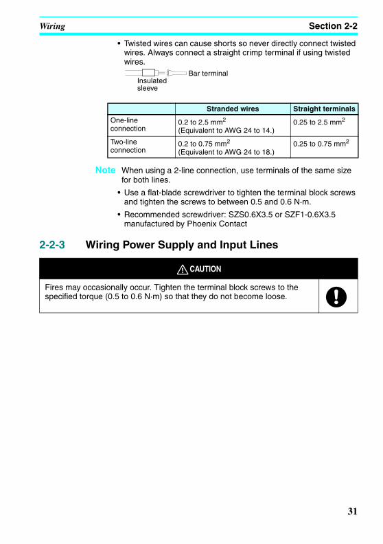
• Twisted wires can cause shorts so never directly connect twisted wires. Always connect a straight crimp terminal if using twisted wires.
Note When using a 2-line connection, use terminals of the same size for both lines.
• Use a flat-blade screwdriver to tighten the terminal block screws and tighten the screws to between 0.5 and 0.6 N·m.
• Recommended screwdriver: SZS0.6X3.5 or SZF1-0.6X3.5 manufactured by Phoenix Contact
2-2-3 Wiring Power Supply and Input Lines
Stranded wires Straight terminals
One-line connection
0.2 to 2.5 mm2 (Equivalent to AWG 24 to 14.)
0.25 to 2.5 mm2
Two-line connection
0.2 to 0.75 mm2 (Equivalent to AWG 24 to 18.)
0.25 to 0.75 mm2
Insulated sleeve
Bar terminal
CAUTION
Fires may occasionally occur. Tighten the terminal block screws to the specified torque (0.5 to 0.6 N·m) so that they do not become loose.
31

Wiring Section 2-2
Z234-01.book Page 32 Tuesday, September 13, 2005 5:22 PM
2-2-4 Wiring CPU Units with AC Power Supplies
Wiring the CPU Unit Power Supply• To prevent voltage drops due to starting currents and inrush
currents in other devices, wire the ZEN power supply circuit separately from other power circuits.
• When using more than one ZEN, to prevent voltage drops due to inrush current and circuit-breaker malfunctions, it is recommended that each one is wired separately.
• To prevent the influence of noise from power lines, twist the power lines. Wiring via a 1-to-1 isolation transformer is also effective.
• Use wires that are thick enough to allow for voltage drops and current variations within the allowable range.
• Include a circuit protector or breaker installed separately from other circuits in the power supply circuit for the ZEN.
Precautions for Correct Use
• Input circuit commons are internally connected to the N terminal of the power circuit for CPU Units with AC power supplies. Wire the L terminal to the power supply of the input device.
Connecting 2-Wire AC SensorsA two-wire sensor cannot be connected directly to the AC input. To connect a two-wire sensor, attach an external bleeder resistance in the way shown below.
Circuit protector
Input device
AC power supply 100 to 240 VAC, 50/60 Hz
Isolation transformer
CPU Unit (AC power supply type)
32

Wiring Section 2-2
Z234-01.book Page 33 Tuesday, September 13, 2005 5:22 PM
• Example: Connecting to a CPU Unit or Expansion I/O Unit
a) Use a resistance that satisfies both of the following conditions.
b) Because of heat generation, use a resistor with at least the following wattage.
Note Calculating the Bleeder Resistance when Connecting an OMRON E2E-X10Y 2-Wire AC SensorThis calculation is based on an input voltage of 85 to 110 V AC.The Sensor’s maximum leakage current is 0.0017 A.The minimum current when the Sensor’s OFF residual voltage is 25 V max. is 0.005 A.
R1 (Ω) ≤ 25 V AC/0.0017 A = 14,706 ΩR2 (Ω) ≤ 85 V AC /0.005 A = 17,000 ΩThe bleeder resistor must thus be 14 kΩ.
The Sensor output current in this case would be 100 VAC/14 kΩ, or 7 mA. This satisfies the Sensor’s control output range of 5 to 300 mA.
P (W) ≥ (110 V AC2)/14 kΩ × 3 = 2.59 W
Thus, a bleeder resistor with a capacity of 3 W must be used.
L
R
N
I0 to I5Two-wire sensor
Internal circuit
R1 (Ω) ≤Max. OFF-voltage for AC input (25 VAC)
Sensor’s max. leakage current (A)
R2 (Ω) ≤Voltage supplied to sensor (V)
Min. current for which the sensor’s OFF residual voltage is less than 25 V (A)
P (W) ≥
(Voltage supplied to sensor)2
Resistance value× 3 (allowance factor)
33

Wiring Section 2-2
Z234-01.book Page 34 Tuesday, September 13, 2005 5:22 PM
2-2-5 Wiring CPU Units with DC Power SuppliesPower Supply and Input Circuits
Connecting a Negative Common (PNP Connection)
Connecting Analog Input Devices to Input Terminals I4 and I5
Connecting Positive Common (NPN Connection)
Precautions for Correct Use
• Apply the power supply voltage through a relay or switch in such a way that the voltage reaches the rated value within 10 s. If the voltage is applied gradually, the power may not be reset or unstable output operations may result.
COM
CPU Unit with10 I/O points
Input device
12 to 24 VDC
COM
CPU Unit with10 I/O points
DC power supply12 to 24 VDC
Note: When connecting an analog input device, always connect the negative side to the COM terminal.
COM
CPU Unit with10 I/O points
Input device
12 to 24 VDCNote: If a positive common is used,
analog input devices cannot be connected to I4 and I5.
34

Wiring Section 2-2
Z234-01.book Page 35 Tuesday, September 13, 2005 5:22 PM
• Connect the COM terminals before turning ON the power supply. Not connecting the COM terminals or connecting them after turning ON the power supply may cause malfunctions.
Connecting Input Devices to the CPU UnitThe following table shows how to connect various input devices.
Note Do not use the following wiring with voltage-output devices:
Device Circuit diagram
Relay output
NPN open collector
NPN current output
PNP current output
Voltage output
IN
COMZEN
+
−
Output
+
0 V
Sensor power supply
IN
COMZEN
+
−
Use the same power supply for the input and sensor.
Constant current circuit
Output
+
0 V
IN
COMZEN
+
−
Sensor power supply
IN
COMZEN
+
−
Output
+
0 V
Sensor power supply
IN
COMZEN
+
−
Output
+
0 V
Sensor power supply
IN
COM (+)
ZEN
+
−
Output
+
0 V
35

Wiring Section 2-2
Z234-01.book Page 36 Tuesday, September 13, 2005 5:22 PM
Leakage Current from Input DevicesA leakage current can cause false inputs when using 2-wire DC sensors (proximity switches or photoelectric switches) or limit switches with LEDs. False inputs won’t occur if the leakage current is less than 0.8 mA. If the leakage current exceeds this value, insert a bleeder resistor in the circuit to reduce the input impedance, as shown in the following diagram.
Note The OFF voltage of the analog/digital input terminals on the CPU Unit is 30 V DC. A 2-wire DC sensor can not be connected.
Refer to page 108 Input Specifications for details on the values LC, IC, and EC. The input impedance, input current, and OFF voltage may vary depending on the input being used.
R ZEN
Input power supply
Bleeder resistor
2-wire sensor, etc.
I: Device's leakage current (mA)R: Bleeder resistance (kΩ)W: Bleeder resistor's power rating (W)
The equations above were derived from the following equations:
LC: ZEN's input impedance (kΩ)IC: ZEN's input current (mA)EC: ZEN's OFF voltage (V) = 5.0 V
R = Lc × 5.0
I × Lc − 5.0kΩ max. W =
2.3R
W min.
R × Input voltage (24)Input Current (Ic)
R + Input voltage (24)Input Current (Ic)
I × ≤ OFF voltage (Ec: 5.0)
W ≥ Input voltage (24)
R × Input voltage (24) × tolerance (4)
36

Wiring Section 2-2
Z234-01.book Page 37 Tuesday, September 13, 2005 5:22 PM
Inductive LoadsWhen connecting an inductive load to an input, connect a diode in parallel with the load. The diode should satisfy the following requirements:
1,2,3... 1. Peak reverse-breakdown voltage must be at least 3 times the load voltage.
2. Average rectified current must be 1 A.
IN
COM
ZENDiode
37

Wiring Section 2-2
Z234-01.book Page 38 Tuesday, September 13, 2005 5:22 PM
2-2-6 Wiring Output CircuitsAll 4 outputs in the relay output circuits have independent contacts. There are no restrictions on polarity.
Output Wiring Precautions
(1) Output Short Circuit Protection
We recommend adding a protective fuse to all output circuits to protect the output elements and PCBs from burning if the load connected to the output terminal short-circuits.
(2) Inductive Loads
When connecting an inductive load to an input, connect a surge protector or diode in parallel with the load.
The surge protector’s components should have the following ratings:
The diode should satisfy the following requirements:
Peak reverse-breakdown voltage must be at least 3 times the load voltage.Average rectified current must be 1 A.
Q0 Q1 Q2 Q3
Load
Load
Load
Load
OUT
COMZEN Surge protector
Relay Output
OUT
COMZEN
Diode
Relay Output
OUT
COM
ZEN
Relay OutputDiode
38
Wiring Section 2-2
Z234-01.book Page 39 Tuesday, September 13, 2005 5:22 PM
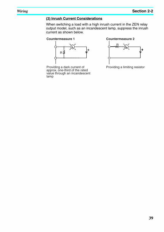
(3) Inrush Current Considerations
When switching a load with a high inrush current in the ZEN relay output model, such as an incandescent lamp, suppress the inrush current as shown below.
R
R
Countermeasure 1
Providing a dark current of approx. one-third of the rated value through an incandescent lamp
Countermeasure 2
Providing a limiting resistor
39

Wiring Section 2-2
Z234-01.book Page 40 Tuesday, September 13, 2005 5:22 PM
40

Z234-01.book Page 41 Tuesday, September 13, 2005 5:22 PM
SECTION 3Programming and Operating Methods
This section explains how to create and edit ladder programs and how to use the timers, counters, comparators, display function and buttons switches.
3-1 Selecting Display Language . . . . . . . . . . . . . . . . . . . . . . . . . . . . . . . . . . . . . 43
3-2 Setting the Date and Time . . . . . . . . . . . . . . . . . . . . . . . . . . . . . . . . . . . . . . . 44
3-3 Creating Ladder Programs . . . . . . . . . . . . . . . . . . . . . . . . . . . . . . . . . . . . . . . 463-3-1 I/O Wiring and Internal Operation . . . . . . . . . . . . . . . . . . . . . . . . . . . . 463-3-2 Clearing Programs . . . . . . . . . . . . . . . . . . . . . . . . . . . . . . . . . . . . . . . . 463-3-3 Writing Ladder Programs . . . . . . . . . . . . . . . . . . . . . . . . . . . . . . . . . . . 47
3-4 Confirming Ladder Program Operation. . . . . . . . . . . . . . . . . . . . . . . . . . . . . 55
3-5 Correcting Ladder Programs . . . . . . . . . . . . . . . . . . . . . . . . . . . . . . . . . . . . . 573-5-1 Changing Inputs . . . . . . . . . . . . . . . . . . . . . . . . . . . . . . . . . . . . . . . . . . 573-5-2 Changing Additional Bit Output Functions . . . . . . . . . . . . . . . . . . . . . 573-5-3 Deleting Inputs, Outputs, and Connection Lines . . . . . . . . . . . . . . . . . 583-5-4 Inserting Lines . . . . . . . . . . . . . . . . . . . . . . . . . . . . . . . . . . . . . . . . . . . 583-5-5 Deleting Blank Lines . . . . . . . . . . . . . . . . . . . . . . . . . . . . . . . . . . . . . . 59
3-6 Using Timers (T) and Holding Timers (#) . . . . . . . . . . . . . . . . . . . . . . . . . . . 603-6-1 Settings in the Ladder Program Edit Screen. . . . . . . . . . . . . . . . . . . . . 623-6-2 Settings in the Parameter Settings Screen . . . . . . . . . . . . . . . . . . . . . . 623-6-3 Parameter Monitor Screen Display. . . . . . . . . . . . . . . . . . . . . . . . . . . . 63
3-7 Using Counters (C) and the 8-Digit Counter (F) . . . . . . . . . . . . . . . . . . . . . . 643-7-1 Settings in the Ladder Program Edit Screen. . . . . . . . . . . . . . . . . . . . . 643-7-2 Settings in the Parameter Settings Screen . . . . . . . . . . . . . . . . . . . . . . 653-7-3 Parameter Monitor Screen Display. . . . . . . . . . . . . . . . . . . . . . . . . . . . 66
3-8 Using Weekly Timers (@) . . . . . . . . . . . . . . . . . . . . . . . . . . . . . . . . . . . . . . . 673-8-1 Settings in the Ladder Program Edit Screen. . . . . . . . . . . . . . . . . . . . . 683-8-2 Settings in the Parameter Settings Screen . . . . . . . . . . . . . . . . . . . . . . 693-8-3 Parameter Monitor Screen Display. . . . . . . . . . . . . . . . . . . . . . . . . . . . 71
3-9 Using Calendar Timers (*) . . . . . . . . . . . . . . . . . . . . . . . . . . . . . . . . . . . . . . 723-9-1 Settings in the Ladder Program Edit Screen. . . . . . . . . . . . . . . . . . . . . 723-9-2 Settings in the Parameter Settings Screen . . . . . . . . . . . . . . . . . . . . . . 723-9-3 Parameter Monitor Screen Display. . . . . . . . . . . . . . . . . . . . . . . . . . . . 73
3-10 Analog Inputs (Analog Comparators (A)) . . . . . . . . . . . . . . . . . . . . . . . . . . . 743-10-1 Settings in the Ladder Program Edit Screen. . . . . . . . . . . . . . . . . . . . . 753-10-2 Settings in the Parameter Settings Screen . . . . . . . . . . . . . . . . . . . . . . 763-10-3 Parameter Monitor Screen Display. . . . . . . . . . . . . . . . . . . . . . . . . . . . 76
3-11 Comparing Timer/Counter Present Values Using Comparators (P) . . . . . . . 773-11-1 Settings in the Ladder Program Edit Screen. . . . . . . . . . . . . . . . . . . . . 773-11-2 Settings in the Parameter Settings Screen . . . . . . . . . . . . . . . . . . . . . . 783-11-3 Parameter Monitor Screen Display. . . . . . . . . . . . . . . . . . . . . . . . . . . . 79
3-12 Comparing the 8-Digit Counter (F) Present Value Using 8-Digit Comparators (G) . . . . . . . . . . . . . . . . . . . . . . . . . . . . . . . . . . . . . . . . . . . . . . 803-12-1 Settings in the Ladder Program Edit Screen. . . . . . . . . . . . . . . . . . . . . 803-12-2 Settings in the Parameter Settings Screen . . . . . . . . . . . . . . . . . . . . . . 803-12-3 Parameter Monitor Screen Display. . . . . . . . . . . . . . . . . . . . . . . . . . . . 81
41

Z234-01.book Page 42 Tuesday, September 13, 2005 5:22 PM
3-13 Displaying Messages (Display Bits (D)) . . . . . . . . . . . . . . . . . . . . . . . . . . . . 823-13-1 Settings in the Ladder Program Edit Screen . . . . . . . . . . . . . . . . . . . . .823-13-2 Settings in the Parameter Settings Screen . . . . . . . . . . . . . . . . . . . . . . .83
3-14 Using Button Input Bits (B) . . . . . . . . . . . . . . . . . . . . . . . . . . . . . . . . . . . . . . 85
42

Selecting Display Language Section 3-1
Z234-01.book Page 43 Tuesday, September 13, 2005 5:22 PM
3-1 Selecting Display LanguageThere is a choice of 6 display languages. The default language is English.
Operation to Select German
Press the OK Button to change to the Menu Screen.
Press the Down Button 4 times to move the cursor to “LANGUAGE”.
Press the OK Button to display the current language (“ENGLISH”). The final “H” will be highlighted and flashing.
Press the OK Button to make the whole word “ENGLISH” flash. A different language can now be selected.
Press the Up Button to select GERMAN.
Press the OK Button to display a confirmation message.
Press the OK Button to complete the setting.
The display language will change to German.
Turn ON the power.
Use the Up/Down Buttons to select a language.
SPANISHITALIANFRENCHGERMANJAPANESEENGLISH
↓
↑
LANGUAGE
GERMAN
LANGUAGE SET? OK/ESC GERMAN
RUNPARAMETERKALENDERSPRACHE
43

Setting the Date and Time Section 3-2
Z234-01.book Page 44 Tuesday, September 13, 2005 5:22 PM
3-2 Setting the Date and TimeThe date and time are not set when the product is shipped. The date and time must be set before the ZEN can be used.
Press the OK Button to display the submenu for clock settings. Select SET CLOCK from the submenu.
Press the OK Button to display the current date and time settings. The right digit of the date will be highlighted and flashing.
Current time: hh:mm (day)
Current date: yy/mm/dd
Press the OK Button to change from a highlighted cursor to a flashing cursor and enable data to be changed.
Set the date and time.
Use the Up/Down Buttons to change the setting.
Use the Left/Right Buttons to move the cursor.
The day will automatically change when the date is set.
Press the OK Button to display a confirmation message.
Press the OK Button to confirm and complete the setting.
Precautions for Correct UseIf the power supply is turned OFF for two days or more at 25°C, the date and time will return to the default setting (00/1/1; 00:00 (SA)). This may cause programs using calendar timers or weekly timers to
PROGRAMRUNPARAMETERSET CLOCK
Select SET CLOCK.
SET CLOCKSUMMER TIME
SET CLOCKyy/mm/dd00/01/0 00:03(SA)
SET CLOCKyy/mm/dd00/01/01 00:03(SA)
Days of the week
SU: SundayMO: MondayTU: TuesdayWE: WednesdayTH: ThursdayFR: FridaySA: Saturday
SET CLOCKyy/mm/dd00/04/01 11:35(SU)
SET CLOCK SET? OK/ESC 11:35(SU)
44

Setting the Date and Time Section 3-2
Z234-01.book Page 45 Tuesday, September 13, 2005 5:22 PM
malfunction. Therefore, mount a Battery Unit for the system if the power supply is expected to be interrupted for an extended time. (Refer to page 96.)
Note 1. The year can be set between 2000 and 2099.
2. If the Daylight Saving Time (DST) is set, “S” will appear at the top right of the time setting screen during the Daylight Saving Time (DST) period. (Refer to page 93.)
SET CLOCK Syy/mm/dd01/05/01 00:00(TU)
“S” displayed during the Daylight Saving Time (DST) period
45
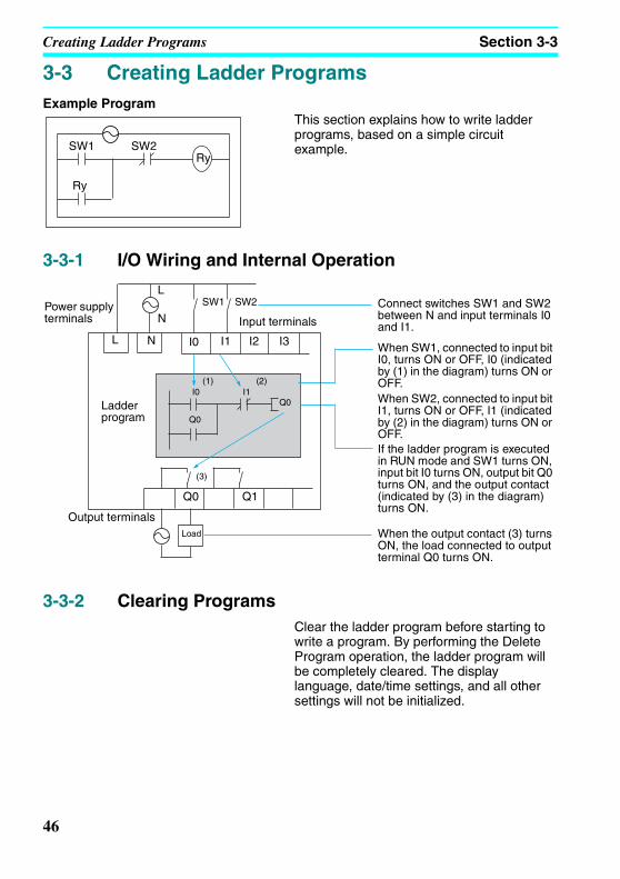
Creating Ladder Programs Section 3-3
Z234-01.book Page 46 Tuesday, September 13, 2005 5:22 PM
3-3 Creating Ladder ProgramsExample Program
This section explains how to write ladder programs, based on a simple circuit example.
3-3-1 I/O Wiring and Internal Operation
3-3-2 Clearing ProgramsClear the ladder program before starting to write a program. By performing the Delete Program operation, the ladder program will be completely cleared. The display language, date/time settings, and all other settings will not be initialized.
SW1 SW2Ry
Ry
Power supply terminals
L
N
SW1 SW2
L N I0 I2 I3I1
I0 I1
Q0
(1) (2)
Q0
(3)
Q0 Q1
Input terminals
Ladder program
Output terminalsLoad
Connect switches SW1 and SW2 between N and input terminals I0 and I1.
When SW1, connected to input bit I0, turns ON or OFF, I0 (indicated by (1) in the diagram) turns ON or OFF.When SW2, connected to input bit I1, turns ON or OFF, I1 (indicated by (2) in the diagram) turns ON or OFF.If the ladder program is executed in RUN mode and SW1 turns ON, input bit I0 turns ON, output bit Q0 turns ON, and the output contact (indicated by (3) in the diagram) turns ON.
When the output contact (3) turns ON, the load connected to output terminal Q0 turns ON.
46

Creating Ladder Programs Section 3-3
Z234-01.book Page 47 Tuesday, September 13, 2005 5:22 PM
Press the OK Button to switch to the Menu Screen and select PROGRAM.
Select DELETE PROG.
If a password has been set, a Password Input Screen will be displayed. Input the password.
Press the OK Button to display a confirmation message, and then select YES.
When the Delete Program operation has been completed, the display will return to the original screen.
3-3-3 Writing Ladder Programs
Press the OK Button to switch to the Menu Screen and select PROGRAM.
Select EDIT PROG.
Press the OK Button to display a confirmation message, and then select YES.
STOP mode display
PROGRAMRUNPARAMETERSET CLOCK
EDIT PROGDELETE PROG
DELETE PROG DELETE? NO YES
EDIT PROGDELETE PROG
STOP mode display
PROGRAMRUNPARAMETERSET CLOCK
EDIT PROGDELETE PROG
EDIT EDIT? NO YES
Press the OK Button to switch to the Ladder Program Edit Screen.
Indicates the line number in the ladder program at the cursor position (line 0 in this example.)
Cursor flashing in a reversed state.
47

Creating Ladder Programs Section 3-3
Z234-01.book Page 48 Tuesday, September 13, 2005 5:22 PM
Operations in the Ladder Program Edit ScreenTwo lines of circuits can be displayed at one time on the Ladder Program Edit Screen.
Up to 96 lines can be written.
Up to 3 inputs and 1 output can be written per line.
• Example ladder diagram
Connection line
Bit addressBit type
Ladder program line number at cursorAdditional output functions
Bit addressBit type
N.C. input
N.O. input
Displayed when there are more lines. Use the Down Button to display the lines.
Displayed when there are more lines. Use the Up Button to display the lines.
Input write positionsBit type/bit numberInput symbol (N.O./N.C) or connection line
Bit/timer/counter/output write positions
Connection line write positions
• Positions for Writing Inputs, Outputs, and Connection Lines
48

Creating Ladder Programs Section 3-3
Z234-01.book Page 49 Tuesday, September 13, 2005 5:22 PM
3-3-3-1 Writing an Input for I0Press the OK Button to display the initial write setting (N.O input I0) and move the flashing cursor to the bit type I position. Use the Up/Down Buttons to select the bit type. Use the Right Button to move the flashing cursor to the 0 position and then use the Up/Down Buttons to select the bit address.
Press the OK Button twice to complete the write operation for input I0. The highlighted cursor will move the next input position.
3-3-3-2 Writing Serial Input I1Press the OK Button to display the N.O. input and input I0 again.
Press the ALT Button to switch to a N.C. input.
(Press the ALT Button again to switch back to a N.O. input.)
Use the Right Button to move the flashing cursor to the bit address position and use the Up Button to change the bit address to 1.
Press the OK Button to move the highlighted cursor to the next input position. A connection will automatically be created between input I0 and the next input.
Writing InputsInput Symbol Configuration
Bit typeBit number
Input symbols ( N.O. input; N.C. input.)
49
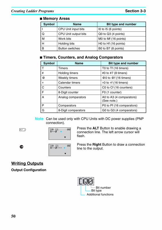
Creating Ladder Programs Section 3-3
Z234-01.book Page 50 Tuesday, September 13, 2005 5:22 PM
Memory Areas
Timers, Counters, and Analog Comparators
Note Can be used only with CPU Units with DC power supplies (PNP connection).
Press the ALT Button to enable drawing a connection line. The left arrow cursor will flash.
Press the Right Button to draw a connection line to the output.
Writing OutputsOutput Configuration
Symbol Name Bit type and number
I CPU Unit input bits I0 to I5 (6 points)
Q CPU Unit output bits Q0 to Q3 (4 points)
M Work bits M0 to Mf (16 points)
H Holding bits H0 to Hf (16 points)
B Button switches B0 to B7 (8 points)
Symbol Name Bit type and number
T Timers T0 to Tf (16 timers)
# Holding timers #0 to #7 (8 timers)
@ Weekly timers @0 to @f (16 timers)
* Calendar timers *0 to *f (16 timers)
C Counters C0 to Cf (16 counters)
F 8-Digit counter F0 (1 counter)
A Analog comparators A0 to A3 (4 comparators) (See note.)
P Comparators P0 to Pf (16 comparators)
G 8-Digit comparators G0 to G3 (4 comparators)
Bit numberBit type
Additional functions
50

Creating Ladder Programs Section 3-3
Z234-01.book Page 51 Tuesday, September 13, 2005 5:22 PM
Memory Areas
Additional Functions for Output Bits
Additional Functions for Bit Outputs
Timers, Holding Timers, Counters, and Display Output Configurations
Symbol Name Bit type and number
Q CPU Unit output bits Q0 to Q3 (4 outputs)
M Work bits M0 to Mf (16 bits)
H Holding bits H0 to Hf (16 bits)
Symbol Name
[ Normal operation
S Set operation
R Reset operation
A Alternate operation
[: Normal output S: Set R: Reset A: Alternate
Q0 turns ON and OFF when execution condition I0 turns ON and OFF.
Q1 turns ON and stays ON when execution condition I1 turns ON once.
Q2 is forced OFF when execution condition I2 turns ON.
Q3 alternates between On and OFF each time execution condition I3 turns ON.
I0
Q0
I1
Q1
I2
Q2
I3
Q3
Timer/counter/display numberTimer/counter/display type
Timer/counter output type
51

Creating Ladder Programs Section 3-3
Z234-01.book Page 52 Tuesday, September 13, 2005 5:22 PM
Timers, Counters, and Display Bits
3-3-3-3 Writing an Output to Q0Press the Right Button again to draw a line to the output and move the highlighted cursor to the output write position.
Press the OK Button to display the initial value for the output (normal output/Q0) and move the flashing cursor to the bit type Q position.
Use the Up/Down Buttons to select the bit type. Use the Right/Left Buttons to move the flashing cursor and use the Up/Down Buttons to select additional functions or select the bit address.
Press the OK Button twice to complete writing output Q0. The highlighted cursor will move to the input at the beginning of the next line.
3-3-3-4 Writing a Parallel Input for Q0Press the OK Button to display input I0 and move the flashing cursor to the bit type I position.
Press the Up Button to select Q (a CPU Unit output bit).
Press the OK Button twice to complete writing the parallel input for Q0. The highlighted cursor will move to the next input.
Symbol Name Type and number Output type
T Timer T0 to Tf (16 timers) T: Trigger
R: Reset# Holding timer #0 to #7 (8 timers)
C Counter C0 to Cf (16 counters) C: Count
D: Count direction
R: Reset
F 8-Digit counter
f0 (1 counter)
D Display bit D0 to Df (16 bits) D
52
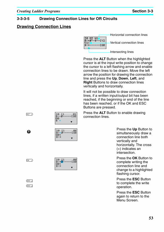
Creating Ladder Programs Section 3-3
Z234-01.book Page 53 Tuesday, September 13, 2005 5:22 PM
3-3-3-5 Drawing Connection Lines for OR Circuits
Drawing Connection Lines
Press the ALT Button when the highlighted cursor is at the input write position to change the cursor to a left flashing arrow and enable connection lines to be drawn. Move the left arrow the position for drawing the connection line and press the Up, Down, Left, and Right Buttons to draw connection lines vertically and horizontally.
It will not be possible to draw connection lines, if a written input/output bit has been reached, if the beginning or end of the line has been reached, or if the OK and ESC Buttons are pressed.
Press the ALT Button to enable drawing connection lines.
Press the Up Button to simultaneously draw a connection line both vertically and horizontally. The cross (+) indicates an intersection.
Press the OK Button to complete writing the connection line and change to a highlighted flashing cursor.
Press the ESC Button to complete the write operation.
Press the ESC Button again to return to the Menu Screen.
Horizontal connection lines
Vertical connection lines
Intersecting lines
53

Creating Ladder Programs Section 3-3
Z234-01.book Page 54 Tuesday, September 13, 2005 5:22 PM
Precautions for Correct UseAlways press the ESC Button and return to the Menu Screen after creating a program. If you do not press the ESC Button and return to the Menu Screen before turning OFF the power, the program and settings will be deleted.
• Do not input a program where the connection lines double back on themselves. The program will not operate properly if such lines are drawn.
• Do not use the same output bit address for more than one output from the program. The resulting operation may not be as expected.
[Q0
[Q0
I0
I1
Here, the final status of Q0 will be controlled by I1, not by I0.
54

Confirming Ladder Program Operation Section 3-4
Z234-01.book Page 55 Tuesday, September 13, 2005 5:22 PM
3-4 Confirming Ladder Program OperationAlways check the ladder program operation before using the ZEN.
Precautions for Safe Use
• Before turning ON the power, check that all wiring has been performed correctly.
• For systems with loads connected to the outputs that may cause serious injury or damage to equipment if operation is incorrect, remove the output wiring before performing trial operation.
• Always ensure safety in the vicinity before switching the operating mode (RUN/STOP).
Procedure for Checking OperationChecks Before Turning ON the Power
1. Check that the ZEN is mounted and wired correctly.
2. Check that the operation of the ZEN will not have a negative impact on the system. Check for any dangers.
3. Turn ON the power supply to the ZEN.Switch to RUN mode while the ZEN is stopped.
Operation Checks4. Turn each input ON and OFF and check that the program is
operating correctly.
5. Adjust any problems.
Method for Checking Operation• Check the operation by the flashing input and output displays on
the Main Screen.
• Check the operation by using the Ladder Program Monitor.
• Connect the ZEN Support Software and check operation using the monitor function. Refer to the operation manual for the ZEN Support Software.
55
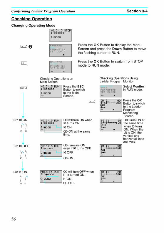
Confirming Ladder Program Operation Section 3-4
Z234-01.book Page 56 Tuesday, September 13, 2005 5:22 PM
Checking OperationChanging Operating Mode
Press the OK Button to display the Menu Screen and press the Down Button to move the flashing cursor to RUN.
Press the OK Button to switch from STOP mode to RUN mode.
PROGRAMRUNPARAMETERSET CLOCK
MONITORSTOPPARAMETERSET CLOCK
RUN
I0 I1
I0 I1
I0 I1
Checking Operations on Main Screen
Press the ESC Button to switch to the Main Screen.
Checking Operations Using Ladder Program Monitor
MONITORSTOPPARAMETERSET CLOCK
RUN
Select Monitor in RUN mode.
Press the OK Button to switch to the Ladder Program Monitoring Screen.
Turn I0 ON. Q0 will turn ON when I0 turns ON.I0 ON.Q0 ON at the same time.
Q0 turns ON at the same time when I0 turns ON. When the bit is ON, the vertical and horizontal lines are thick.
Turn I0 OFF. Q0 remains ON even if I0 turns OFF.I0 OFF.
Q0 ON.
Turn I1 ON. Q0 will turn OFF when I1 is turned ON.I1 ON.Q0 OFF.
RUN
RUN
RUN
RUN
RUNRUN
RUN
RUN
56

Correcting Ladder Programs Section 3-5
Z234-01.book Page 57 Tuesday, September 13, 2005 5:22 PM
3-5 Correcting Ladder Programs
3-5-1 Changing InputsChange contact Q0 to M1.
Press the OK Button to change the highlighted cursor to a flashing cursor and move the flashing cursor to the bit type position.
Use the Up/Down Buttons to select M.
Press the Right Button to move the flashing cursor to the bit address position. Use the Up/Down Buttons to change the bit address from 0 to 1.
Press the OK Button to complete the setting change.
3-5-2 Changing Additional Bit Output FunctionsChange the additional function for the input for Q0 to S (Set).
Press the OK Button to change the highlighted cursor to a flashing cursor.
Press the Left Button to move the flashing cursor to the additional function position.
Press the Up Button twice to change the additional function from [ to S.
Press the OK Button to complete the change.
Move the highlighted cursor to the input to be changed.
Move the highlighted cursor to the output to be changed.
57

Correcting Ladder Programs Section 3-5
Z234-01.book Page 58 Tuesday, September 13, 2005 5:22 PM
3-5-3 Deleting Inputs, Outputs, and Connection LinesMove the highlighted cursor to the position of the input, output, or connection line to be deleted and press the DEL Button.
Example: Deleting Serial Input M3
Press the DEL Button to delete the input and the related connecting lines at the same time.
Example: Deleting Vertical Connecting LinesMove the highlighted cursor to the input position to the right of the vertical line to be deleted. Press the ALT Button to enable drawing connection lines. The highlighted cursor will change to a left arrow cursor.
Press the DEL Button to delete the vertical connection line.
3-5-4 Inserting Lines• To insert a blank line, move the highlighted cursor to the beginning of the line where
the blank line is to be inserted and press the ALT Button.
Press the ALT Button to insert one blank line.
• To add OR programming, inputs can be added between parallel inputs. Move the highlighted cursor to the beginning of the line where the input is to be inserted.
Move the high-lighted cursor to the position of the input to be deleted.
Move the highlighted cursor to the beginning of the next line (the line that will be after the inserted line.)
A circuit will be added here.
Blank line
Move the highlighted cursor to the beginning of the next line (the line that will be after the inserted line.)
An input will be added here.
58

Correcting Ladder Programs Section 3-5
Z234-01.book Page 59 Tuesday, September 13, 2005 5:22 PM
Press the ALT Button to reserve a 1-line space between the parallel inputs.
The vertical connection lines will be automatically extended.
Note A blank line cannot be inserted if an input or connection line is written in the last line (the 96th line).
3-5-5 Deleting Blank LinesTo delete a blank line, move the highlighted cursor to the input position at the beginning of the line to be deleted and press the DEL Button.
Press the DEL Button to delete one blank line. All following lines will move up one.
Note A line must be blank to be deleted, i.e., lines containing inputs and outputs cannot be deleted.
Blank line
Move the high-lighted cursor to the beginning of the line to be deleted. This line will be deleted.
59

Using Timers (T) and Holding Timers (#) Section 3-6
Z234-01.book Page 60 Tuesday, September 13, 2005 5:22 PM
3-6 Using Timers (T) and Holding Timers (#)The ZEN has 16 built-in timers and 8 built-in holding timers.
Timer Usage and Operation
Timers The present value being timed will be reset when the timer switches from RUN mode to STOP mode or the power is turned OFF.
There are five uses of the timer available, depending on the additional function selection.
Holding timers The present value being timed is held even when the timer switches from RUN mode to STOP mode or the power is turned OFF. The time will continue when the trigger input turns ON again. The ON status of the timer bit is also held when the timer times out.
Only ON-delay holding timers are supported.
X: ON delay timer
Turns ON after a set interval after the trigger input has turned ON.
Basic Operation
Main Applications
Time lag operations
: OFF delay timer
Stays ON while the trigger input is ON and turns OFF after a set interval after the trigger input has turned OFF.
Basic Operation
Main Applications
Useful for timing lighting and ventilating fans.
Reset input
Trigger input
SettingPresent value
Timer bit0 Trigger input
Time
Output
Reset input
Trigger input
SettingPresent value
Timer bit0
Trigger inputTime
Output
60

Using Timers (T) and Holding Timers (#) Section 3-6
Z234-01.book Page 61 Tuesday, September 13, 2005 5:22 PM
Holding Timer Usage and Operation
O: One-shot pulse timer
Remains ON for a set interval when the trigger input turns ON.
Basic Operation
Main Applications
Useful for fixed-quantity operation when operation is always required for the same period.
F: Flashing pulse timer
Turns ON and OFF repeatedly at set intervals while the trigger input is ON.
Basic Operation
Main Applications
Useful as an alarm circuit for flashing emergency lighting or buzzers.
W: Twin timer
Turns ON and OFF repeatedly at set intervals while the trigger input is ON. The ON time and OFF time can be set independently.
Basic Operation
Main Applications
Convenient for intermittent operation, such as that used for fans.
X: ON delay timer only
Turns ON after a set interval after the trigger input has turned ON. The present value is held while the trigger input is OFF.
Main applications
When operation is to be continued even during momentary power interruptions and longer power interruptions. Also used for time-lag operation.
Reset input
Trigger input
SettingPresent value
Timer bit0 Trigger input
Time
Output
Reset input
Trigger input
SettingPresent value
Timer bit0 Trigger input
Time
Output
Time Time Time
Reset input
Trigger input
Present value
Timer bit0
ON timeOFF time
Trigger inputONtime
Output
OFFtime
ONtime
OFFtime
Reset input
Trigger input
SettingPresent value
Timer bit
0
61
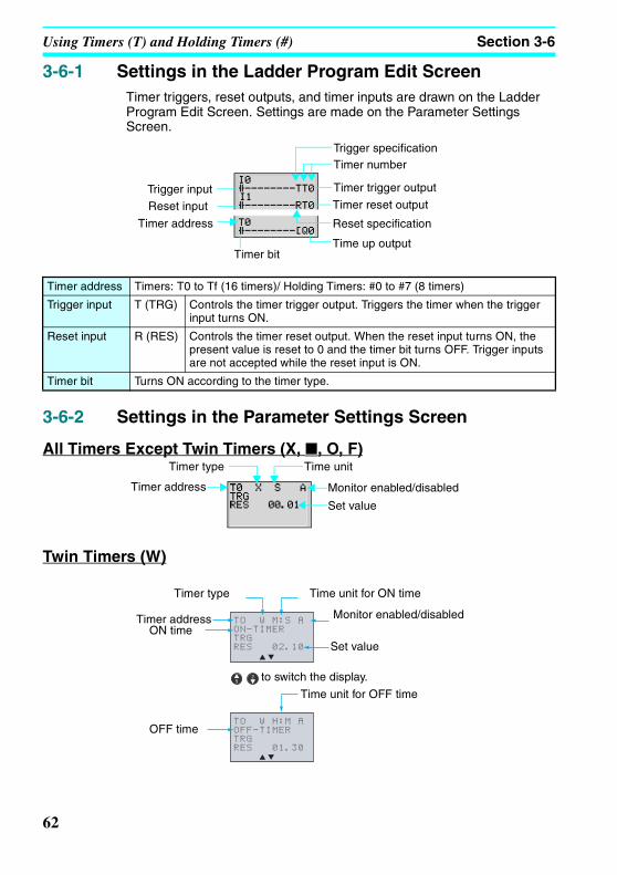
Using Timers (T) and Holding Timers (#) Section 3-6
Z234-01.book Page 62 Tuesday, September 13, 2005 5:22 PM
3-6-1 Settings in the Ladder Program Edit ScreenTimer triggers, reset outputs, and timer inputs are drawn on the Ladder Program Edit Screen. Settings are made on the Parameter Settings Screen.
3-6-2 Settings in the Parameter Settings Screen
All Timers Except Twin Timers (X, , O, F)
Twin Timers (W)
Timer address Timers: T0 to Tf (16 timers)/ Holding Timers: #0 to #7 (8 timers)
Trigger input T (TRG) Controls the timer trigger output. Triggers the timer when the trigger input turns ON.
Reset input R (RES) Controls the timer reset output. When the reset input turns ON, the present value is reset to 0 and the timer bit turns OFF. Trigger inputs are not accepted while the reset input is ON.
Timer bit Turns ON according to the timer type.
Timer numberTrigger specification
Timer trigger output
Timer reset output
Reset specification
Time up output
Trigger input
Reset input
Timer address
Timer bit
Timer type Time unit
Monitor enabled/disabled
Set value
Timer address
TO W M:S A
ON-TIMER
TRG
RES 02.10
TO W H:M A
OFF-TIMER
TRG
RES 01.30
Timer type Time unit for ON time
Monitor enabled/disabled
Set value
Timer addressON time
Time unit for OFF time
OFF time
to switch the display.
62

Using Timers (T) and Holding Timers (#) Section 3-6
Z234-01.book Page 63 Tuesday, September 13, 2005 5:22 PM
Timer Types
Time Units and Settings
Monitor Enabled or Disabled
3-6-3 Parameter Monitor Screen Display
All Timers Except Twin Timers
Twin Timers
X ON delay
OFF delay
O One-shot pulse
F Flashing pulse
W Twin
S 00.01 to 99.99 s (in 0.01-s units)
M:S 00 min 01 s to 99 min 59 s (in minutes and seconds)
H:M 00 h 01 m to 99 h 59 m (in hours and minutes)
A Operating parameters can be monitored and settings changed.
D Operating parameters cannot be monitored nor settings changed.
Trigger input status ( : OFF/ : ON)
Reset input status ( : OFF/ : ON)
Timer present value
Timer bit status ( : OFF/ : ON)
Timer setting
RUN
TO W M:S A
ON-TIMER
TRGo 00.00o
RESo 02.10
TO W H:M A
OFF-TIMER
TRGo 00.00o
RESo 01.13
to switch the display.
Trigger input status ( : OFF/ : ON)
Reset input status ( : OFF/ : ON)
ON timer present value
Timer bit status ( : OFF/ : ON)ON timer setting
OFF timer present value
Timer bit status ( : OFF/ : ON)OFF timer setting
63

Using Counters (C) and the 8-Digit Counter (F) Section 3-7
Z234-01.book Page 64 Tuesday, September 13, 2005 5:22 PM
3-7 Using Counters (C) and the 8-Digit Counter (F)Up to 16 counters and one 8-digit counter can be used in incremental or decremental mode. The present value for counters and the status of counter bits (ON/OFF) are held even when the operating mode is changed or there is a power interruption.
OperationCounter bits turn ON when the count value (present value) exceeds the setting (present value ≥ set value). The count returns to 0 and the bits turns OFF when the reset input turns ON. Count inputs are not accepted while the reset input is ON.
3-7-1 Settings in the Ladder Program Edit ScreenOutputs for the counter input, counter direction, and counter reset are written in the Ladder Program Edit Screen. Counter input conditions can also be written. Settings are made in the Parameter Settings Screen.
Counter address Counter C0 to Cf (16 points)
8-Digit Counter F0 (1 point)
Counter input C (CNT) Increments (or decrements) each time the count input turns ON.
Counter direction specification input
D (DIR) Switches between incremental and decremental counting.
OFF: Incremental
ON: Decremental
I1 (DIR)
I0 (CNT)
I3 (RES)
0
Set value
Counter bit
Present value
Counter address
Count input specification
Count input
Counter direction specification input
Reset inputReset specificationCounter address
Counter bit
Output to counter input
Counter direction specification outputCounter direction specificationCounter reset output
Counter bit output
64

Using Counters (C) and the 8-Digit Counter (F) Section 3-7
Z234-01.book Page 65 Tuesday, September 13, 2005 5:22 PM
3-7-2 Settings in the Parameter Settings Screen
Counters (C)
The speed of the counter depends on whether a filter is used. Refer to page 90.
8-Digit Counter (F)
Note Counting Speed
The maximum counting speed of the 8-digit counter is 150 Hz regardless of whether an input filter is used. The maximum ladder program capacity, however, may be less than 150 Hz. Calculate the cycle time (refer to page 114) and confirm the maximum
Reset input R (RES) When the reset input turns ON, the present value returns to 0 and the counter bit turns OFF. Count inputs are not accepted while the reset input is ON.
Count input Turns ON when the counter has counted out (PV ≥ SV)
Set value 0001 to 9999 (4 decimal digits) times
Monitor enabled/disabled
A Operating parameters can be monitored and settings changed.
D Operating parameters cannot be monitored or settings changed.
Monitor enabled/disabledSet value
Counter address
Set value 00000001 to 99999999 (4 decimal digits) times
Counter speed H High speed (150 Hz, see note.) (I0 for CPU Units with DC power supplies only)
L Low speed (Depends on whether a filter is used. Refer to page 90.)
Monitor enabled/disabled
A Operating parameters can be monitored and settings changed.
D Operating parameters cannot be monitored or settings changed.
Monitor enabled/disabled
Set value
Counter address
Counter speed
65
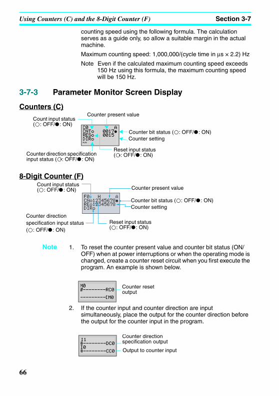
Using Counters (C) and the 8-Digit Counter (F) Section 3-7
Z234-01.book Page 66 Tuesday, September 13, 2005 5:22 PM
counting speed using the following formula. The calculation serves as a guide only, so allow a suitable margin in the actual machine.
Maximum counting speed: 1,000,000/(cycle time in µs × 2.2) Hz
Note Even if the calculated maximum counting speed exceeds 150 Hz using this formula, the maximum counting speed will be 150 Hz.
3-7-3 Parameter Monitor Screen Display
Counters (C)
8-Digit Counter (F)
Note 1. To reset the counter present value and counter bit status (ON/OFF) when at power interruptions or when the operating mode is changed, create a counter reset circuit when you first execute the program. An example is shown below.
2. If the counter input and counter direction are input simultaneously, place the output for the counter direction before the output for the counter input in the program.
Counter bit status ( : OFF/ : ON)
Count input status ( : OFF/ : ON)
Counter setting
Counter present value
Reset input status ( : OFF/ : ON)Counter direction specification
input status ( : OFF/ : ON)
RUN
Counter bit status ( : OFF/ : ON)
Count input status ( : OFF/ : ON)
Counter setting
Counter present value
Reset input status ( : OFF/ : ON)
Counter direction specification input status ( : OFF/ : ON)
Counter reset output
Counter directionspecification output
Output to counter input
66

Using Weekly Timers (@) Section 3-8
Z234-01.book Page 67 Tuesday, September 13, 2005 5:22 PM
3-8 Using Weekly Timers (@)Any of the following three operations, which vary in the day of week, time, and output time settings, can be selected for weekly timers.
Weekly Timer OperationWeekly timer
opera-tion
Operation
N
Nor
mal
ope
ratio
n
Typical Timer Operation
Timer Operation Extending Past Midnight
Mon24:00
17:30
8:150:00
Weekly timer bit
Stop time
Start time
Tues Wed
Date setting
Thurs Fri Sat Sun
Tim
e se
tting
In this example, the weekly timer turns ON every day from Tuesday to Friday between 8:15 and 17:30.
Mon24:0023:00
5:000:00
Start time
Stop time
Tues Wed
Date setting
Thurs Fri Sat Sun
Weekly timer bit
Tim
e se
tting
In this example, the weekly timer turns ON every day from Tuesday to Friday between 23:00 and 5:00.
67

Using Weekly Timers (@) Section 3-8
Z234-01.book Page 68 Tuesday, September 13, 2005 5:22 PM
3-8-1 Settings in the Ladder Program Edit ScreenWeekly timer inputs are written in the Ladder Program Edit Screen. Settings are made in the Parameter Settings Screen.
D
Mul
tiple
-day
ope
ratio
n
P
Pul
se o
utpu
t ope
ratio
nWeekly timer
opera-tion
Operation
Mon24:00
17:30
8:150:00
Stop time
Start time
Tues Wed
Date setting
Thurs Fri Sat Sun
Weekly timer bit
Tim
e se
tting
In this example, the weekly timer turns ON from 8:15 on Tuesday to 17:30 on Friday.
Mon24:00
8:150:00
Start time
Tues Wed
Date setting
Thurs Fri Sat Sun
Weekly timer bit
Tim
e se
tting
Operation time setting: 15 minutes, 30 seconds
In this example, the weekly timer turns ON for 15 minutes 30 seconds from 8:15 every day from Tuesday to Friday.
Weekly timer addresses @0 to @f (16 timers)
Time up output
Weekly timer address
68

Using Weekly Timers (@) Section 3-8
Z234-01.book Page 69 Tuesday, September 13, 2005 5:22 PM
3-8-2 Settings in the Parameter Settings Screen
Normal Operation (N)
Note When the flashing cursor is on the start day, press the Right Button and then the Up/Down Buttons to set the stop day. If the stop day is not set, the timer will operate according to the set time only.
Operation between Days (D)
Type of operation
N Normal
D Between days
P Pulse
Day Start day Sun/Mon/Tues/Wed/Thurs/Fri/Sat
Stop day Sun/Mon/Tues/Wed/Thurs/Fri/Sat/None
Time Start time 00:00 to 23:59
Stop time 00:00 to 23:59
Operating time 00:01 to 99:59 (mm:ss)
Monitor enabled/disabled
A Operating parameters can be monitored and settings changed.
D Operating parameters cannot be monitored or settings changed.
Monitor enabled/disabled
Weekly timer address
Stop dayStart day
Start time
Stop time
Type of operation
@0 D A
ON SU 01:10
OFFMO 03:31
Monitor enabled/disabled
Weekly timer address
Stop day
Start day
Start timeStop time
Type of operation
69

Using Weekly Timers (@) Section 3-8
Z234-01.book Page 70 Tuesday, September 13, 2005 5:22 PM
Pulse Operation (P)
Relationship between Start and Stop Days and Times
Note The multiple-day operation shown here is for when the start and stop days are the same (SU-SU).
1. Start time is before stop time (ON: 08:00/OFF: 17:00): Operates from 08:00 Sunday until 17:00 Sunday.
2. Start time is after stop time (ON: 21:00/OFF: 06:00): Operates from 21:00 Sunday until 06:00 the following Sunday.
3. Start and stop times are the same: Operates regardless of the time.
Setting and operation Setting example
Operation
Start and stop day
When start day is before stop day
MO - FR Operates Monday to Friday every week.
When start day is after stop day
FR - MO Operates every Friday through to the following Monday.
When start and stop days are the same
SU - SU Normal and pulse operation: Operates regardless of the day of the week.
Multiple-day operation: Operates every Sunday only (See note.)
When stop day not set
SU - Normal and pulse operation: Operates every Sunday only.
Multiple-day operation: Cannot be set.
Start and stop time (normal operation)
When start time is before stop time
ON: 08:00OFF: 17:00
Operates 8:00 to 17:00 every day.
When start time is after stop time
ON: 21:00OFF: 06:00
Operates 21:00 to 6:00 the next day.
When start and stop times are the same
ON: 13:00OFF: 13:00
Operates regardless of the time.
@0 P SU-MO A
ON 01:10
13M30S
Monitor enabled/disabled
Weekly timer address
Stop dayStart day
Start timeOperating time
Type of operation
70

Using Weekly Timers (@) Section 3-8
Z234-01.book Page 71 Tuesday, September 13, 2005 5:22 PM
3-8-3 Parameter Monitor Screen Display
Normal Operation (N)
Operation between Days (D)
Pulse Operation (P)
RUN
Weekly timer bit status ( : OFF/ : ON)
Stop day
Start day
Current dayCurrent time
Start timeStop time
Type of operation
RUN
@0 D A
MO 09:32ON SU 13:10
OFF TU 10:30
Weekly timer bit status ( : OFF/ : ON)
Stop day
Start day
Current day
Current time
Start timeStop time
Type of operation
RUN
@0 P SU-MO A
MO 09:32 ON 09:30
13M30S
Weekly timer bit status ( : OFF/ : ON)
Stop dayStart day
Current day
Current time
Start timeOperating time setting
Type of operation
71

Using Calendar Timers (*) Section 3-9
Z234-01.book Page 72 Tuesday, September 13, 2005 5:22 PM
3-9 Using Calendar Timers (*)Calendar timers turn ON between specified dates.
Calendar Timer Operation
3-9-1 Settings in the Ladder Program Edit ScreenCalendar timer inputs are written in the Ladder Program Edit Screen. Settings are made in the Parameter Settings Screen.
3-9-2 Settings in the Parameter Settings Screen
Note To stop operation on August 31, set the stop date to the following day (September 1).
Dec 31End date Sep 1
Apr 1
Jan 1
Start date
Calendar timer bit The calendar timer bit is ON between April
1 and August 31.
Calendar timer address *0 to *f (16 timers)
Calendar timer address
Time up output
*0 A
ON 01/01
OFF01/01
Calendar timer address
Monitor enabled/disabledStart dateStop date
Start date Jan 1 to Dec 31
Stop date (See note.) Jan 1 to Dec 31
Monitor enabled/disabled
A Operating parameters can be monitored and settings changed.
D Operating parameters cannot be monitored or settings changed.
72
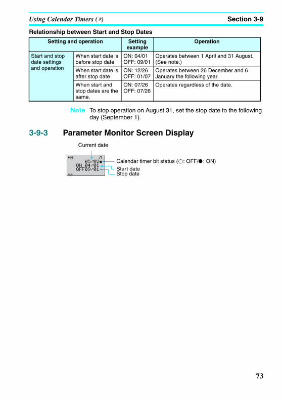
Using Calendar Timers (*) Section 3-9
Z234-01.book Page 73 Tuesday, September 13, 2005 5:22 PM
Relationship between Start and Stop Dates
Note To stop operation on August 31, set the stop date to the following day (September 1).
3-9-3 Parameter Monitor Screen Display
Setting and operation Setting example
Operation
Start and stop date settings and operation
When start date is before stop date
ON: 04/01OFF: 09/01
Operates between 1 April and 31 August. (See note.)
When start date is after stop date
ON: 12/26OFF: 01/07
Operates between 26 December and 6 January the following year.
When start and stop dates are the same.
ON: 07/26OFF: 07/26
Operates regardless of the date.
Start dateStop date
Current date
Calendar timer bit status ( : OFF/ : ON)
RUN
73

Analog Inputs (Analog Comparators (A)) Section 3-10
Z234-01.book Page 74 Tuesday, September 13, 2005 5:22 PM
3-10 Analog Inputs (Analog Comparators (A))Two analog voltage inputs between 0 and 10 V can be incorporated into the CPU Units with a DC power supply. I4 and I5 for CPU Units can be used as analog voltage inputs.
The analog input signal is converted to BCD (00.0 to 10.0). The results can be used with one of the comparators A0 to A3, and the 4 comparison outputs can be used as input conditions in the program.
Note Connect the negative side to COM for analog inputs. The analog input circuit may be destroyed if the positive side is connected to COM.
COM
10C3DR-D-V2
DC12-24V
12 to 24 VDC
+ −
Analog signal input: 0.0 to 10.0 VDevice with analog voltage output
(DC power supply type)Analog input 1: I4Analog input 2: I5
74

Analog Inputs (Analog Comparators (A)) Section 3-10
Z234-01.book Page 75 Tuesday, September 13, 2005 5:22 PM
Operation
Precautions for Correct UseDo not make negative signal inputs to analog inputs. If negative signals are made, the internal elements may be damaged.
3-10-1 Settings in the Ladder Program Edit ScreenThe analog comparator input is written in the Ladder Program Edit Screen. Settings are made in the Parameter Settings Screen.
10.0
00.0
10.510.0
5.2
00.00.0 10.0 V
10.5 V
• Example 1(When comparison shows analog input 1 ≥ 5.2 V)
Setting
Analog comparator bit
Input voltage
• Example 2(When comparison shows analog input 1 is ≤ analog input 2)
The analog comparator bit turns ON when the analog input voltage reaches is 5.2 V or higher.
Analog comparator bit
Converted value
Analog input 1
Analog input 2
The analog comparator bit turns ON when the analog input 2 voltage is higher than the analog input 1 voltage.
Analog comparator address A0 to A3 (4 comparators)
Analog comparator bit
Comparison result output
75

Analog Inputs (Analog Comparators (A)) Section 3-10
Z234-01.book Page 76 Tuesday, September 13, 2005 5:22 PM
3-10-2 Settings in the Parameter Settings Screen
Refer to page 17 for parameter setting methods.
Comparison data 1 determines the comparison pattern. When comparing to a constant, the constant is set for comparison data 2 next. The operator is specified last.
3-10-3 Parameter Monitor Screen Display
• Comparing Analog Inputs and Constants(When I4 ≥ constant)
Analog comparator address
Comparison data 1Operator
Monitor enabled/disabled
Comparison data 2
• Comparing Analog Inputs(When I4 ≤ I5)
Analog comparator address
Comparison data 1Operator
Monitor enabled/disabled
Comparison data 2
Analog comparator address
A0 to A3 (4 comparators)
Comparison data
1 I4: Analog input 1
I5: Analog input 2
Comparison Patterns
• Size comparison between I4 and I5.
• Size comparison between I4 and constant.
• Size comparison between I5 and constant.
2 I5: Analog input 2
Constant: 00.0 to 10.5
Operator >=: Analog comparator bit turns ON when comparison data 1 ≥ comparison data 2.
<=: Analog comparator bit turns ON when comparison data 1 ≤ comparison data 2.
Monitor enabled/disabled
A Operating parameters can be monitored and settings changed.
D Operating parameters cannot be monitored or settings changed.
• Comparing Analog Inputs and Constants(When I4 ≥ constant)
• Comparing Analog Inputs(When I4 ≤ I5)
Analog input 1 (I4) present value
Analog comparator bit status ( : OFF/ : ON)
Analog input 1 (I4) present value
Analog comparator bit status ( : OFF/ : ON)
Analog input 2 (I5) present valueRUN RUN
76

Comparing Timer/Counter Present Values Using Comparators (P) Section 3-11
Z234-01.book Page 77 Tuesday, September 13, 2005 5:22 PM
3-11 Comparing Timer/Counter Present Values Using Comparators (P)
Timer (T), holding timer (#), and counter (C) present values can be compared. The present values of the same type of timer or counter can be compared, or they can be compared to constants.
Operation
3-11-1 Settings in the Ladder Program Edit ScreenComparator inputs are written in the Ladder Program Edit Screen. Settings are made in the Parameter Settings Screen.
0
• Example 1(When comparison setting is holding timer #0 ≥ 12 min 34 s)
• Example 2(When comparison setting is counter 1 (C1) ≤ counter 2 (C2))
Setting
12 min 34 s
Comparator bit
#0 present value
Comparator bit
C1 present value
C2 present value
Comparator addresses P0 to Pf (16 points)
Comparator bit
Comparison result output
77

Comparing Timer/Counter Present Values Using Comparators (P) Section 3-11
Z234-01.book Page 78 Tuesday, September 13, 2005 5:22 PM
3-11-2 Settings in the Parameter Settings Screen
Note Press the ALT Button to switch between comparison data 2 timer/counter address and constants.
Comparison type T: Timer
#: Holding timer
C: Counter
Comparison data 1 T: T0 to Tf Timers 0 to f
#: #0 to #7 Holding timers 0 to 7
C: C0 to Cf Counters 0 to f
* Size comparison between T and T or T and constant.
* Size comparison between # and # or # and constant.
* Size comparison between C and C or C and constant.
2 T: T0 to Tf Timers 0 to f
#: #0 to #7 Holding timers 0 to 7
C: C0 to Cf Counters 0 to f
Constant: 00.00 to 99.99 when comparison type is T/#
0000 to 9999 when comparison type is C
Operator >=: Timer/counter comparator bit turns ON when comparison data 1 ≥ comparison data 2.
<=: Timer/counter comparator bit turns ON when comparison data 1 ≤ comparison data 2.
Monitor enabled/disabled
A Operating parameters can be monitored and settings changed.
D Operating parameters cannot be monitored or settings changed.
• Comparing Holding Timers and Constants(When Holding Timer #0 ≥ 12 min 34 s)
• Comparing Counters(When counter 1 (C1) ≤ counter 2 (C2))
Comparator address
Comparison data 1Comparison type
Monitor enabled/disabled
Operator
Comparison data 2
Comparator address
Comparison data 1Comparison type
Monitor enabled/disabled
Operator
Comparison data 2
78

Comparing Timer/Counter Present Values Using Comparators (P) Section 3-11
Z234-01.book Page 79 Tuesday, September 13, 2005 5:22 PM
3-11-3 Parameter Monitor Screen Display
Note The time unit is determined as follows when timers or holding timers have been specified under comparison type:
a) When a constant has been set to as comparison data 2, the time unit is automatically aligned with the unit for comparison data 1 timers or holding timers.
b) The time units are automatically aligned when the units are different for comparison data 1 and 2 timers.
• Comparing Holding Timers and Constants(When Holding Timer #0 ≥ 12 min 34 s)
• Comparing Counters(When counter 1 (C1) ≤ counter 2 (C2))
Holding timer 0 (#0) present value
Timer/counter comparator bit status( : OFF/ : ON)
Counter 1 (C1) present value
Timer/counter comparator bit status( : OFF/ : ON)
Counter 2 (C2) present value
RUN RUN
79

Section 3-12Comparing the 8-Digit Counter (F) Present Value Using 8-Digit Comparators (G)
Z234-01.book Page 80 Tuesday, September 13, 2005 5:22 PM
3-12 Comparing the 8-Digit Counter (F) Present Value Using 8-Digit Comparators (G)
The present value of the 8-digit counter (F) can be compared to a constant.
Operation
Example for 8-Digit Counter ≥ 12000000
3-12-1 Settings in the Ladder Program Edit ScreenComparator inputs are written in the Ladder Program Edit Screen. Settings are made in the Parameter Settings Screen.
3-12-2 Settings in the Parameter Settings Screen
F0 present value
8-Digit Comparator bit
12000000
8-Digit comparator addresses G0 to G3 (4 bits)
Comparator bit
Comparison result output
G0 A
F0
>=
12000000
• Example for 8-Digit Counter ≥ 12000000
8-Digit comparator address
Monitor enabled/disabledOperatorComparison data
Comparison item
80

Section 3-12Comparing the 8-Digit Counter (F) Present Value Using 8-Digit Comparators (G)
Z234-01.book Page 81 Tuesday, September 13, 2005 5:22 PM
Refer to page 17 for parameter setting methods.
3-12-3 Parameter Monitor Screen Display
Comparison item 8-Digit counter (F0)
Comparison data Constant: 00000000 to 99999999
Operator >=: Comparator bit turns ON when 8-digit counter present value ≥ Comparison data.
<=: Comparator bit turns ON when 8-digit counter present value ≤ Comparison data.
Monitor enabled/disabled
A Operating parameters can be monitored.
D Operating parameters cannot be monitored.
G0 A
F0 123456789
>=
12000000
• Example for 8-Digit Counter ≥ 12000000
8-Digit counter present value
8-Digit comparator bit status( : OFF/ : ON)
81

Displaying Messages (Display Bits (D)) Section 3-13
Z234-01.book Page 82 Tuesday, September 13, 2005 5:22 PM
3-13 Displaying Messages (Display Bits (D))A user-specified message, the time the message is displayed, a timer/counter present value, or an analog conversion value can be displayed on the LCD screen. If multiple display functions are used, multiple data can be displayed on the same screen.
Display Bits Operation
Note 1. The ZEN ladder program is executed in order of ascending line numbers. If more than one item is displayed on the same line, the display function that was executed last will be shown on the display and previous ones will be deleted.
2. The display clear function will erase all displays from the specified digit on (i.e., the display will be blank). If the display clear function is executed for the same line after another display function, the characters will still be erased from the specified digit on.
3-13-1 Settings in the Ladder Program Edit ScreenThe display functions are written in the Ladder Program Edit Screen. Settings are made in the Parameter Settings Screen.
• Operation Example 1 • Operation Example 2
Monitors the system operation status. Displays the date and time that the system error occurred.
Settings Details Settings Details
Display address D0 to Df (16 points)
Execution condition
Display
Clear display
82

Displaying Messages (Display Bits (D)) Section 3-13
Z234-01.book Page 83 Tuesday, September 13, 2005 5:22 PM
3-13-2 Settings in the Parameter Settings Screen
Note 1. When L0 or L1 are selected to disable the display function screen, the display function screen will not be displayed automatically. Use operation buttons to move to the display function screen.
2. When L2 or L 3 are selected (switching to display function screen), the ZEN switches to the display function screen if the display function is enabled and the specified data is displayed. The Main Screen will no longer be displayed. To display the Main Screen, change the CPU Unit to STOP mode.
Backlight/display function screen switching
L0 No backlight; No switching to display function screen (See note 1.)
L1 Backlight; No switching to display function screen (See note 1.)
L2 No backlight; Switching to display function screen (See note 2.)
L3 Backlight; Switching to display function screen (See note 2.)
Display start position
X (digit): 00 to 11
Y (line): 0 to 3
Display object CHR Characters (12 max.: Alphanumeric characters and symbols)
DAT Month/day (5 digits: @@/@@)
DAT1 Day/month (5 digits: @@/@@)
CLK Hour/minutes (5 digits: @@:@@)
I4, I5 Analog conversion (4digits: @@.@)
T0 to Tf Timer present value (5 digits: @@.@@)
#0 to #7 Holding timer present value (5 digits: @@.@@)
C0 to Cf Counter present value (4 digits: @@@@)
F0 8-Digit counter present value (8 digits: @@@@@@@@)
Monitor enabled/disabled
A Operating parameters can be monitored.
D Operating parameters cannot be monitored.
Backlight/display function screen switching
Monitor enabled/disabledDisplay start positionDisplay object Display character string (Set when character string selected as display object.)
Display character string candidatesCharacter string cursor position
Display address
X00 to to X11
Y0
Y3
to
83

Displaying Messages (Display Bits (D)) Section 3-13
Z234-01.book Page 84 Tuesday, September 13, 2005 5:22 PM
Settings when Character (CHR) Selected
Use the Right Button to move the character string position to the right. Use the Left Button to move the character string to the left.
Table of Display Characters
Move the highlighted cursor to the display character string column.
Display character string columns (12 characters max.)
Candidates for display character string
Character string cursor position
Position within character string Flash simultaneously while settings are being madeCharacter to be selected
Characters before and after character to be selected
D0 L0 ATRG X00Y0(00) CHR[ !][~ ]
D0 L0 ATRG X00Y0(00) CHR
[~!][• ]
( )Use the Up/Down Buttons to scroll through the candidate characters.
Alternates display of the candidate character and the position mark.
Candidate is highlighted and flashing.
( )
! " # $ % & ' ( ) * + , - . /
0 1 2 3 4 5 6 7 8 9 : ; < = > ?
@ A B C D E F G H I J K L M N O
P Q R S T U V W X Y Z [ \ ] ^ _
‘ a b c d e f g h i j k l m n o
p q r s t u v w x y z |
84

Using Button Input Bits (B) Section 3-14
Z234-01.book Page 85 Tuesday, September 13, 2005 5:22 PM
3-14 Using Button Input Bits (B)The operation buttons are assigned operations of input bits. They are useful when checking program operations or forcefully resetting timer/counter present values.
Button switch address Operation button
B0 ESC
B1 OK
B2 Down
B3 Left
B4 Right
B5 Up
B6 DEL
B7 ALT
B6 B7
B0 B1
B3
B5
B4
B2
3
85

Using Button Input Bits (B) Section 3-14
Z234-01.book Page 86 Tuesday, September 13, 2005 5:22 PM
Using Button Input Bits• The buttons can also be used as “hidden keys” for software resets of counters or
holding bit present values.
Press the DEL+ALT Buttons simultaneously during operation to reset the counter C2 present value to 0 and the holding bit H5 to OFF.
Note
• When a button is pressed, e.g., to make a menu selection, the operation defined for the button in the ladder program as a button switch (B) will also be executed. This may cause unexpected results, such as an output turning ON/OFF. Be sure to test the program completely.
• The ESC+OK Buttons are used to switch menu displays. We recommend not using these as button switches (B).
86

Z234-01.book Page 87 Tuesday, September 13, 2005 5:22 PM
SECTION 4Special Functions
This section describes how to protect ladder programs, stabilize inputs, make LCD screen adjustments, and make summer time settings.
4-1 Protecting Programs. . . . . . . . . . . . . . . . . . . . . . . . . . . . . . . . . . . . . . . . . . . . 884-1-1 Setting a Password . . . . . . . . . . . . . . . . . . . . . . . . . . . . . . . . . . . . . 894-1-2 Deleting Registered Passwords . . . . . . . . . . . . . . . . . . . . . . . . . . . 89
4-2 Stabilizing Input Operations . . . . . . . . . . . . . . . . . . . . . . . . . . . . . . . . . . . . . 904-3 Changing Backlight Automatic Cutout Time . . . . . . . . . . . . . . . . . . . . . . . . 924-4 Setting Daylight Saving Time (DST). . . . . . . . . . . . . . . . . . . . . . . . . . . . . . . 934-5 Reading System Information . . . . . . . . . . . . . . . . . . . . . . . . . . . . . . . . . . . . . 94
87

Protecting Programs Section 4-1
Z234-01.book Page 88 Tuesday, September 13, 2005 5:22 PM
4-1 Protecting ProgramsThe ZEN has a password function to prevent incorrect manipulation of ladder programs or settings data by other operators.
Precautions for Correct UseAlways record your password for future reference when using the password function. You will no longer be able to operate the ZEN if you forget your password.
• The password setting range is 0000 to 9999 (4 decimal digits).
• You will no longer be able to perform the following operations if the password is not input correctly.
Edit ladder programs
Clearing programs
Monitor ladder programs
Change or delete the password
Set the input filter
RS-485 communications settings
• When any of these functions is selected from the menu, the Password Input Screen will be displayed. If the password is input correctly, the display will move to the next screen for the selected function. However, if the password is input incorrectly, the next screen will not be displayed.
88

Protecting Programs Section 4-1
Z234-01.book Page 89 Tuesday, September 13, 2005 5:22 PM
4-1-1 Setting a Password
Press the OK Button to change to a flashing cursor and enable a password to be set.
Set the password.
Use the Left and Right Buttons to move to the digit to be changed.
Use the Up/Down Buttons to input a numeral between 0 and 9.
Press the OK Button. A confirmation message will be displayed.
Note The display will automatically change to the Waiting for Password Input Screen when making settings that require a password to be input. Use the same method as outlined above to input the registered password.
4-1-2 Deleting Registered PasswordsPress the OK Button to change to a flashing cursor and to enable password setting.
Input the registered password.
Use the Left and Right Buttons to move to the digit to be changed.
Use the Up/Down Buttons to input a numeral between 0 and 9.
PARAMETERSET CLOCKLANGUAGEOTHER
Select Other.
PASSWORDBACKLIGHTINPUT FILTERSYSTEM INF
Select Password.
PASSWORD
0000
PASSWORD
1234
PASSWORD SET? OK/ESC
1234
The icon will appear at the bottom right of the screen when a password has been registered.
PASSWORDBACKLIGHTINPUT FILTERSYSTEM INF
Select Other/Password.
PASSWORD
0000
PASSWORD
1234
89

Stabilizing Input Operations Section 4-2
Z234-01.book Page 90 Tuesday, September 13, 2005 5:22 PM
Press the OK Button to display a message asking whether or not to delete the set password.
If the input password does not match the registered password, the display will return to the original screen.
If the input password does not match the registered password, a CHECK ERR message will be displayed. Re-enter the password correctly.
4-2 Stabilizing Input OperationsIf external input contacts chatter, ZEN operation may become unstable. Set an input filter to stabilize operation. Input filters can be set separately for the CPU Unit and each Expansion I/O Unit.
Operation (Example: DC Input Circuits)
PASSWORD CANCEL? OK/ESC
1234
PASSWORD
BACKLIGHT
INPUT FILTER
SYSTEM INF
The icon will disappear when the password is deleted.
If the password was correct, press the OK Button to delete the password.
PASSWORD CANCEL? CHECK ERR
1233
15 ms 15 ms 15 ms 15 ms 15 ms 15 ms
50 ms 50 ms 50 ms 50 ms
Input detection voltage
Input
Input circuit detection(With input filter)
Input circuit detection(No input filter)
90
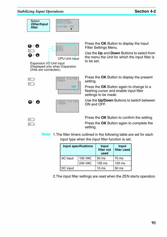
Stabilizing Input Operations Section 4-2
Z234-01.book Page 91 Tuesday, September 13, 2005 5:22 PM
Press the OK Button to display the Input Filter Settings Menu.
Use the Up and Down Buttons to select from the menu the Unit for which the input filter is to be set.
Press the OK Button to display the present setting.
Press the OK Button again to change to a flashing cursor and enable input filter settings to be made.
Use the Up/Down Buttons to switch between ON and OFF.
Press the OK Button to confirm the setting.
Press the OK Button again to complete the setting.
Note 1.The filter timers outlined in the following table are set for each input type when the input filter function is set.
2.The input filter settings are read when the ZEN starts operation.
PASSWORDBACKLIGHTINPUT FILTERSYSTEM INF
Select Other/Input filter.
INNEREXP1EXP2EXP3
/
/CPU Unit input
Expansion I/O Unit input (Displayed only when Expansion Units are connected.)
OFF
INPUT FILTERINNER
OFF
INPUT FILTERINNER
ON
/
Input specifications Input filter not
used
Input filter used
AC input 100 VAC 50 ms 70 ms
240 VAC 100 ms 120 ms
DC input 15 ms 50 ms
91

Changing Backlight Automatic Cutout Time Section 4-3
Z234-01.book Page 92 Tuesday, September 13, 2005 5:22 PM
4-3 Changing Backlight Automatic Cutout TimeThe LCD backlight automatically turns ON when button operations are performed. It then turns OFF automatically 2 minutes after button operations stop. The default backlight cutout setting of 2 minutes can be changed to 10 or 30 minutes or the backlight can be set to remain ON continuously.
Press the OK Button to display the current backlight cutout setting.
Press the OK Button again to change to a flashing cursor and enable backlight cutout time settings to be made.
Use the Up and Down Buttons to set the cutout time.
Press the OK Button to confirm the setting.
Press the OK Button again to complete the setting.
Note The backlight cutout time is used not only to determine if and when the backlight turns OFF after button operations have stopped. If backlight has been specified to turn ON with the display function, the same setting is used to determine if and when the backlight turns OFF once the execution of the display function has been completed.
Button operation
Operation starts
. . . . . Operation stops
Display function (when L1 or L3 is set)
. . . . . Cutout time
Backlight status
ON Remains ON. Remains ON. Turns OFF.
DD0
OFF → ON
DD0
ON → OFF
PASSWORDBACKLIGHTINPUT FILTERSYSTEM INF
Select Other/Backlight.
2min
BACKLIGHT
2min
BACKLIGHT
10min
/
ON (Continuously ON)30 min10 min2 min
92

Setting Daylight Saving Time (DST) Section 4-4
Z234-01.book Page 93 Tuesday, September 13, 2005 5:22 PM
4-4 Setting Daylight Saving Time (DST)Set the Daylight Saving Time (DST) function when using the ZEN in countries that use Daylight Saving Time (DST).
Press the OK Button to display the current settings.
Press the OK Button again to change to a flashing cursor and enable Daylight Saving Time (DST) settings to be made.
Use the Up and Down Buttons to make the setting.
Press the OK Button to confirm the setting.Press the OK Button again to complete thesetting.
Note When Daylight Saving Time (DST) has been set, an “S” will appear at the top right of the Time Settings Screen during the Daylight Saving Time (DST) period.
SET CLOCKSUMMER TIME
Select Time/Summertime.
CANCEL
SUMMER TIME
CANCEL
SUMMER TIME
EU TYPE
/
NZ Type (for Daylight Saving Time (DST) in New Zealand)
AU Type (for Daylight Saving Time (DST) in Australia)
US Type (for Daylight Saving Time (DST) in USA)
EU Type (for Daylight Saving Time (DST) in Europe)
Manual (for manual settings)
Cancel (for no Daylight Saving Time (DST))
Cancel Daylight Saving Time (DST) settings are not made. Any Daylight Saving Time (DST) settings that have been made will be deleted.
Manual Moves the clock forward 1 hour.
EU Type Daylight Saving Time (DST) period:
2:00 a.m last Sunday in March to 2:00 a.m. last Sunday in October
Once the start time (2:00 a.m.) has been reached, the clock is moved forward 1 hour to 3:00 a.m. When the stop time (2:00 a.m) has been reached, the clock is moved backwards 1 hour to 1:00 a.m.
US Type Daylight Saving Time (DST) period:
2:00 a.m first Sunday in April to 2:00 a.m. last Sunday in October
AU Type Daylight Saving Time (DST) period:
2:00 a.m last Sunday in October to 2:00 a.m. last Sunday in March
NZ Type Daylight Saving Time (DST) period:
2:00 a.m first Sunday in October to 3:00 a.m. last Sunday in March
Once the start time (2:00 a.m.) has been reached, the clock is moved forward 1 hour to 3:00 a.m. When the stop time (3:00 a.m) has been reached, the clock is moved backwards 1 hour to 2:00 a.m.
93

Reading System Information Section 4-5
Z234-01.book Page 94 Tuesday, September 13, 2005 5:22 PM
4-5 Reading System InformationThe software version of the CPU Unit, the number of CPU Unit I/O points, and other information can be read.
SET CLOCK Syy/mm/dd01/05/01 00:00(TU)
"S" displayed during the Daylight Saving Time (DST) period.
PASSWORDBACKLIGHTINPUT FILTERSYSTEM INF
Select Other/System information.
/
U03.00050701INT:I06O04EX1:I00O00EX2:I00O00EX3:I00O00RMT:I00000LCD:YESRTC:YESADC:NO
Software version (e.g., Ver 3.00)Date software created (e.g., 2005 July 1)No. of CPU Unit I/O points (e.g., 6 inputs, 4 outputs)No. of Expansion Unit 1 I/O pointsNo. of Expansion Unit 2 I/O pointsNo. of Expansion Unit 3 I/O points(For function expansion)Availability of LCD screen (e.g., Yes)Availability of calendar and time function (e.g., Yes)Availability of analog input (e.g., No)
94

Z234-01.book Page 95 Tuesday, September 13, 2005 5:22 PM
SECTION 5Optional Products
This section describes how to mount Battery Units, use Memory Cassettes, and how to connect the ZEN Support Software.
5-1 Mounting Battery Units . . . . . . . . . . . . . . . . . . . . . . . . . . . . . . . . . . . . . . . . . 965-2 Using Memory Cassettes . . . . . . . . . . . . . . . . . . . . . . . . . . . . . . . . . . . . . . . . 975-3 Connecting the ZEN Support Software . . . . . . . . . . . . . . . . . . . . . . . . . . . . . 99
95

Mounting Battery Units Section 5-1
Z234-01.book Page 96 Tuesday, September 13, 2005 5:22 PM
5-1 Mounting Battery UnitsLadder programs and all settings are saved to the CPU Unit EEP-ROM but calendar, clock, and holding timer bits and holding timer/counter present values are held by the capacitor. Therefore, if the power supply is interrupted for 2 days or more (at 25°C), this data will be reset. Mount a Battery Set (optional) for systems where the power supply may be interrupted for long periods.
Mounting Method
1,2,3... 1. Tilt the Battery Unit to the side and insert the claw at the bottom of the Battery Unit into the mounting hole on the left side of the CPU Unit.
2. Connect the Battery Unit cord to the CPU Unit connector.
3. Push the claw at the top of the Battery Unit into the CPU Unit.
3
ZEN-BAT01 Battery Unit
96

Using Memory Cassettes Section 5-2
Z234-01.book Page 97 Tuesday, September 13, 2005 5:22 PM
Precautions for Correct Use
• Turn OFF the power supply to the CPU Unit before mounting the Battery Unit.
• Do not remove the label from the left side of the CPU Unit if a Batter Unit is not mounted.
Note The Battery Unit has a life of 10 years min.
5-2 Using Memory CassettesOptional Memory Cassettes can be used to save the ladder program and settings and to copy programs and settings to other CPU Units.
Mounting Memory Cassettes
1,2,3... 1. Remove the connector cover on the front of the ZEN.
WARNING
A lithium battery is used in the Battery Unit. Do not short the battery terminals or charge, disassemble, deform under pressure, or incinerate the battery. Doing any of these may occasionally result in serious injury due to ignition or rupture of the battery. Never use any battery that has been dropped on the floor or otherwise subjected to excessive shock.
Connector cover
3
(Use a flat-blade screwdriver if the cover is difficult to remove.)
97

Using Memory Cassettes Section 5-2
Z234-01.book Page 98 Tuesday, September 13, 2005 5:22 PM
2. Mount the Memory Cassette.
Precautions for Correct UseAlways turn OFF the power supply to the CPU Unit before removing or mounting Memory Cassettes.
Transferring Programs
Select Cassette.
The Operation Menu for Memory Cassettes will be displayed.
Use the Up/Down Buttons to move the flashing cursor and press the OK Button to select an operation.
Note 1. The transferable program includes the ladder programs, parameters, and all settings data. The present values for the timers, holding timers, counters, and holding bits cannot be transferred.
2. Only error-free programs can be transferred. The program will not be transferred if there is any illegal data in the program.
3. The Memory Cassette can be written to up to 100,000 times.
ZEN-ME01 Memory Cassette
PROGRAMRUNPARAMETERSET CLOCK
Select Program in STOP mode.
EDIT PROGDELETE PROGCASSETE
SAVE(CPU~MC)LOAD(MC~CPU) ERASE/
Menu Operation
Save (CPU Unit to MC) Saves CPU Unit programs to the Memory Cassette. Existing programs on the Memory Cassette will be overwritten.
Load (MC to CPU Unit) Transfers programs from the Memory Cassette to the CPU Unit.
Erase Initializes the Memory Cassette (i.e. deletes programs).
98

Connecting the ZEN Support Software Section 5-3
Z234-01.book Page 99 Tuesday, September 13, 2005 5:22 PM
5-3 Connecting the ZEN Support SoftwareThe ZEN Support Software can be used for programming and monitoring. Refer to the ZEN-SOFT01-V4 ZEN Support Software Operation Manual (Z184-E1-02) for information on the functions and operation of the ZEN Support Software.
Computer Specifications
Note When connecting to a computer that does not have a serial port, connect an RS-232C−USB Conversion Cable to the ZEN-CIF01 Computer Connecting Cable. An OMRON CS1W-CIF31 Conversion Cable can be used (cable length: 50 cm).
Item Conditions
Operating system Windows 95, 98, ME, 2000, XP, NT4.0 Service Pack 3
CPU Pentium 133 MHz or faster(Pentium 200 MHz or faster recommended)
Memory 64 Mbytes min.
HD capacity 40 Mbytes free disk space min.
CD-ROM drive Required.
Communications 1 serial (COM) port
Keyboard and mouse Required
Monitor 800 x 600 dots (SVGA) min.; 256 colors min.
3
CPU Units
ZEN-CIF01 Personal Computer Connecting Cable
ZEN-SOFT01-V4ZEN Support Software
Windows computer
99

Connecting the ZEN Support Software Section 5-3
Z234-01.book Page 100 Tuesday, September 13, 2005 5:22 PM
100

Z234-01.book Page 101 Tuesday, September 13, 2005 5:22 PM
SECTION 6Troubleshooting
This section lists the error messages and provides probable causes and countermeasures for troubleshooting.
6-1 Troubleshooting . . . . . . . . . . . . . . . . . . . . . . . . . . . . . . . . . . . . . . . . . . . . . . . 102
6-2 Error Messages. . . . . . . . . . . . . . . . . . . . . . . . . . . . . . . . . . . . . . . . . . . . . . . . 102
6-3 Deleting Error Messages . . . . . . . . . . . . . . . . . . . . . . . . . . . . . . . . . . . . . . . . 104
101

Troubleshooting Section 6-1
Z234-01.book Page 102 Tuesday, September 13, 2005 5:22 PM
6-1 TroubleshootingSearch for the cause of the error and take immediate countermeasures if ERR or any other error message appears on the LCD screen.
6-2 Error MessagesThe following tables list the error messages that are displayed when an error occurs.
Power ON but No Operation
Note I/O Verification Error
Analog comparators (A): Used with AC power supply type.
Display function (D):
• For AC power supply types, analog-converted values (I4/I5) are specified as the displayed items.
ERR
3
CPU Unit
Error message Probable cause Possible solution
MEMORY ERR Program error. The ladder program and parameter settings have been cleared. Write a program to the ZEN again.
I/O VRFY ERR Bit type that cannot be used with system configuration included in ladder program. (See note.)
Remove the illegal bit type from the program.
102

Error Messages Section 6-2
Z234-01.book Page 103 Tuesday, September 13, 2005 5:22 PM
Error at Power ON or During Operation
Error During Program Transfer from Memory Cassette
Error message Probable cause Possible solution
MEMORY ERR Program error. Execute the All Clear operation and then re-write the program.
I2C ERR Communications error between Memory and RTC.
Press any operation button and clear the error. Replace the CPU Unit if the error occurs frequently.
Error message Probable cause Possible solution
M/C ERR Memory cassette program error.
Save the error-free program to the Memory Cassette again.
103

Deleting Error Messages Section 6-3
Z234-01.book Page 104 Tuesday, September 13, 2005 5:22 PM
6-3 Deleting Error MessagesA flashing error message is displayed when an error occurs. Turn OFF the power supply and remove the cause of the error.
Press any operation button to delete the error message. Once the error has been removed the display will return to normal.
Press either the ESC, OK, DEL, ALT, Left/Right, or Up/Down Buttons. Any button can be pressed to delete the error message.
Press any button to return to normal display.
Note The error display will remain for internal errors that cannot be fixed, such as I/O Bus errors and I/O Unit Over errors.
I/O VRFY ERR
Error Message Display Screen
ERR
ERR will remain on the display.
104

Z234-01.book Page 105 Tuesday, September 13, 2005 5:22 PM
Appendix ASpecifications
RatingsItem Specifications
ZEN-10C3AR-A-V2 ZEN-10C3DR-D-V2
Power supply voltage 100 to 240 VAC, 50/60 Hz 12 to 24 VDC (ripple: 5% max.)
Rated power supply voltage
85 to 264 VAC, 47/63 Hz 10.8 to 28.8 VDC
Power consumption 100 VAC: Approx. 4 VA240 VAC: Approx. 5.6 VA
12/24 VDC: Approx. 2.5 W
Inrush current 2 A max. 50 A max.
Ambient temperature 0 to 55°C
Ambient humidity 10% to 90% (with no condensation)
Storage temperature –20 to 75°C
Terminal block Solid-wire terminal block, tightening torque: 0.5 to 0.6 N⋅mDegree of protection IP20 (Mounted inside a control panel)
105
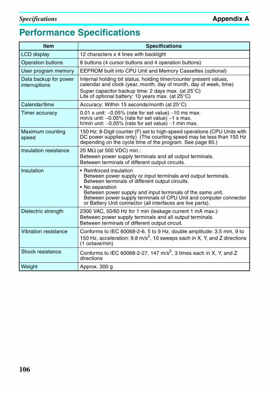
Specifications Appendix A
Z234-01.book Page 106 Tuesday, September 13, 2005 5:22 PM
Performance SpecificationsItem Specifications
LCD display 12 characters x 4 lines with backlight
Operation buttons 8 buttons (4 cursor buttons and 4 operation buttons)
User program memory EEPROM built into CPU Unit and Memory Cassettes (optional)
Data backup for power interruptions
Internal holding bit status, holding timer/counter present values, calendar and clock (year, month, day of month, day of week, time)Super capacitor backup time: 2 days max. (at 25°C)Life of optional battery: 10 years max. (at 25°C)
Calendar/time Accuracy: Within 15 seconds/month (at 25°C)
Timer accuracy 0.01 s unit: −0.05% (rate for set value) −10 ms max.min/s unit: −0.05% (rate for set value) −1 s max.h/min unit: −0.05% (rate for set value) −1 min max.
Maximum counting speed
150 Hz: 8-Digit counter (F) set to high-speed operations (CPU Units with DC power supplies only) (The counting speed may be less than 150 Hz depending on the cycle time of the program. See page 65.)
Insulation resistance 20 MΩ (at 500 VDC) min.:Between power supply terminals and all output terminals. Between terminals of different output circuits.
Insulation • Reinforced insulationBetween power supply or input terminals and output terminals. Between terminals of different output circuits.
• No separationBetween power supply and input terminals of the same unit.Between power supply terminals of CPU Unit and computer connector or Battery Unit connector (all interfaces are live parts).
Dielectric strength 2300 VAC, 50/60 Hz for 1 min (leakage current 1 mA max.): Between power supply terminals and all output terminals. Between terminals of different output circuit.
Vibration resistance Conforms to IEC 60068-2-6, 5 to 9 Hz, double amplitude: 3.5 mm, 9 to 150 Hz, acceleration: 9.8 m/s2, 10 sweeps each in X, Y, and Z directions (1 octave/min)
Shock resistance Conforms to IEC 60068-2-27, 147 m/s2, 3 times each in X, Y, and Z directions
Weight Approx. 300 g
106
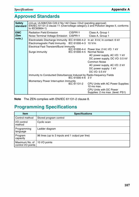
Specifications Appendix A
Z234-01.book Page 107 Tuesday, September 13, 2005 5:22 PM
Approved Standards
Note The ZEN complies with EN/IEC 61131-2 clause 8.
Programming Specifications
Safety standard
cULus: UL508/CSA C22.2 No.142 Class I Div2 (pending approval)EN/IEC 61131-2 clause 11 (Overvoltage category 2 and Pollution degree II, conforms to IEC60664-1)
EMC (See note.)
Radiation Field Emission CISPR11 Class A, Group 1Noise Terminal Voltage Emission CISPR11 Class A, Group 1
Electrostatic Discharge Immunity IEC 61000-4-2 In air: 8 kV, In contact: 6 kVElectromagnetic Field Immunity IEC 61000-4-3 10 V/mElectrical Fast Transient/Burst Immunity
IEC 61000-4-4 Power line: 2 kV, I/O: 1 kV Surge immunity IEC 61000-4-5 Normal Noise
AC power supply, AC I/O: 1 kV DC power supply, DC I/O: 0.5 kVCommon Noise AC power supply, AC I/O: 2 kV DC power supply: 1 kV DC I/O: 0.5 kV
Immunity to Conducted Disturbances Induced by Radio-frequency FieldsIEC 61000-4-6 3 V
Momentary Power Interruption ImmunityIEC 61131-2 CPU Units with AC Power Supplies:
10 ms max.CPU Units with DC Power Supplies: 2 ms max. (level: PS1)
Item Specifications
Control method Stored program control
I/O control method
Cyclic scan
Programming language
Ladder diagram
Program capacity
96 lines (up to 3 inputs and 1 output per line)
Maximum No. of control I/O points
10 I/O points
107

Specifications Appendix A
Z234-01.book Page 108 Tuesday, September 13, 2005 5:22 PM
Input Specifications
CPU Units
AC Inputs (Not Isolated)
Note Can be selected using the input filter settings.
Memory areas CPU Unit input bits (I) I0 to I5, 6 bits
CPU Unit output bits (Q) Q0 to Q3, 4 bits
Work bits (M) M0 to Mf, 16 bits
Holding bits (H) H0 to Hf, 16 bits
Button switches (B) B0 to B7, 8 bits
Timers (T) T0 to Tf, 16 timers
Holding timers (#) #0 to #7, 8 timers
Weekly timers (@) @0 to @f, 16 timers(not supported for LED-type CPU Units)
Calender timers (*) *0 to *f, 16 timers(not supported for LED-type CPU Units)
Counters (C) C0 to Cf, 16 counters
8-Digit Counter (F) F0, 1 counter
Display bits (D) D0 to Df, 16 bits
Analog comparator (A) A0 to A3, 4 comparators (CPU Units with DC power supply only)
Comparator (P) P0 to Pf, 16 comparators
8-Digit comparator (G) G0 to G3, 4 comparators
Item Specifications Circuit drawing
Input voltage 100 to 240 VAC +10%, –15%, 50/60 Hz
Input impedance 680 kΩInput current 0.15 mA/100 VAC, 0.35 mA/240 VAC
ON voltage 80 VAC min.
OFF voltage 25 VAC max.
ON response time
50 ms or 70 ms at 100 VAC (See note.)
100 ms or 120 ms at 240 VAC (See note.)OFF response
time
Item Specifications
IN
IN
100 to 240 VAC
N
L
330 kΩ
51 kΩ
300 kΩ
Internal circuit
108

Specifications Appendix A
Z234-01.book Page 109 Tuesday, September 13, 2005 5:22 PM
DC Inputs I0 to I3 (Not Isolated)
Note Can be selected using the input filter settings, except when I0 is being used for high-speed input.
DC Inputs I4 and I5 (Not Isolated)
Note Can be selected using the input filter settings.
Item Specifications Circuit drawing
Input voltage 12 to 24 VDC +20%, –10%
Input impedance 5.3 kΩInput current 4.5 mA Typical (24 VDC)
ON voltage 8 VDC min.
OFF voltage 5 VDC max.
ON response time
15 ms or 50 ms (See note.)
OFF response time
Item Specifications Circuit drawing
DC inputs
Input voltage 12 to 24 VDC +20%, –10%
* When using analog function.
Input impedance
PNP: 5.5 kΩ (14 VDC min.)100 kΩ (14 VDC max.)
NPN: 5.2 kΩInput current PNP: 4.3 mA, Typical (24 VDC)
NPN: 4.6 mA, Typical (24 VDC)
ON voltage 8 VDC min.
OFF voltage 3 VDC max.
ON response time
15 ms or 50 ms (See note.)
OFF response time
Analog inputs
Input range 0 to 10 V
External input impedance
100 kΩ min.
Resolution 0.1 V (1/100 FS)
Accuracy ±1.5% FS (at ambient operating temperature within rated range)
AD conversion data
0 to 10.5 V in 0.1 V increments
to IN
IN12 to 24 VDC
5.1 kΩ
COM
1.8 kΩ
Internal circuit
+to IN
COM
12 to 24 VDC
47 kΩ
27 kΩ
6.2 kΩ
150 kΩ
−
220 kΩ
47 kΩ5.6 kΩ
Inte
rnal
ci
rcui
t
Analog output device
109

Specifications Appendix A
Z234-01.book Page 110 Tuesday, September 13, 2005 5:22 PM
Output Specifications
Guidelines for the normal durability of the ZEN relay outputs are shown in the following diagram.
Item Specifications Circuit drawing
Max. switching capacity
250 VAC/8 A (cosφ = 1)24 VDC/5 A
The total for all outputs must be 20 A max. for each Unit.
Each circuit is made up of an independent common circuit.
Min. switching capacity
5 VDC, 10 mA
Relay durability
Electrical Resistive load: 50,000 timesInductive load: 50,000 times (cosφ = 0.4)
Mechanical 10 million times
ON response time 15 ms max.
OFF response time 5 ms max.
L
Q0 to Q3/ OUT0 to OUT3
Inte
rnal
ci
rcui
t
1,000
500
300
100
50
30
100 2 4 6 8 10
Usage: 360 times/hour
250 VAC resistive load24 VDC resistive load/250 VAC inductive load24 VDC inductive load (1.7 ms)
Contact current (A)
Dur
abili
ty (
x 10
3 )
Note The switching capacity, switching durability, and applicable load area when actually using the relay depend on the type of load, environmental conditions, and switching conditions. Therefore, be sure to confirm these conditions for the actual machine before use.
110

Specifications Appendix A
Z234-01.book Page 111 Tuesday, September 13, 2005 5:22 PM
External Dimensions
6070
90 80 45
4456
4.7(Sliding, 13 max.)
45
4487.5
7017.5
ZEN-BAT01
3
3
• ZEN-10C3@R-@-V2
• Dimensions with the Battery Unit Mounted
70
4.7(Sliding, 13 max.)
60
90 80
5644
45
• Switching Power Supply UnitZEN-PA03024
111

Specifications Appendix A
Z234-01.book Page 112 Tuesday, September 13, 2005 5:22 PM
112

Z234-01.book Page 113 Tuesday, September 13, 2005 5:22 PM
Appendix BLadder Program Execution
Executing Ladder ProgramsZEN executes up to 96 lines of a ladder program in one cycle from first to last line. Starting from the first line of the bus bar, the ZEN repeatedly executes each line from left to right.
Note 1. The time from when processing starts at the bus bar until the bus bar is returned to at the first line again to execute the entire ladder program is called cycle time.
2. The output ON/OFF results cannot be used for inputs within the same cycle. The result scan be used from the next cycle onwards.
[Q0
[Q1
TT0
[Q2
0
1
2
3
4
I0 I1 I2
Q0
I3
I4
T0
Bus bar Repeatedly executes in order from bus bar.
00
01
I0[M0
[Q0
I0
M0 M0
Q0
1 cycle 1 cycle
The Q0 ON/OFF result is reflected one cycle after MO turns ON or OFF.
113

Ladder Program Execution Appendix B
Z234-01.book Page 114 Tuesday, September 13, 2005 5:22 PM
Cycle Time Calculation Method
Refer to the following table for ZEN execution times. The execution times are provided as a guide. External factors, button operations, execution of ZEN Support Software operations, and timing of the processing affects the actual processing times.
Common Processing Time
Ladder Program Execution Time
Cycle time (µs) = Common processing time
+ Ladder program execution time
Unit type Common processing time
Economy-type CPU Units 850 µs
Per line 30 µs: Line containing program
7 µs: Empty lines
*1
Per output CPU Unit output bits (Q) 4 µs *2
Work bits (M)
Holding bits (H)
Timers (T)/Holding timers (#) 15 µs *3
Counters (C)/8-Digit Counters (F) 13 µs
Display bits (D) Hour and minute (CLK)/Year and month (DAT)/Month and day (DAT1): 21 µs
Timers (T)/Holding timers (#)/Counters (C)/Analog comparators: 28 µs
Characters (CHR)/8-Digit Counters (F): 38 µs
Weekly timers (@) 4 µs *4
Calendar timers (*) 1 µs
Analog comparators (A) 2 µs
Comparators (P) 7 µs *5
8-Digit Comparators (G) 4 µs
114
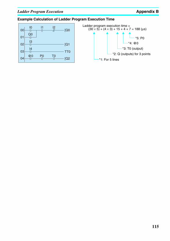
Ladder Program Execution Appendix B
Z234-01.book Page 115 Tuesday, September 13, 2005 5:22 PM
Example Calculation of Ladder Program Execution Time
[Q0
[Q1
TT0
[Q2
00
01
02
03
04
I0 I1 I2
Q0
I3
I4
@0 P0 T0
Ladder program execution time = (30 × 5) + (4 × 3) + 15 + 4 + 7 = 188 (µs)
*5: P0
*4: @0
*3: T0 (output)
*2: Q (outputs) for 3 points
*1: For 5 lines
115

Ladder Program Execution Appendix B
Z234-01.book Page 116 Tuesday, September 13, 2005 5:22 PM
116

Z234-01.book Page 117 Tuesday, September 13, 2005 5:22 PM
Appendix COperating Mode at Startup
The operating mode at startup depends on the presence of a user program as shown in the following table.
Yes: Indicates that the user ladder program and parameter settings are correctly written.
No: Indicates that the user ladder program and parameter settings are not written or that the data is not correct.
User program
In CPU No Yes No Yes
In Memory Cassette
No No Yes Yes
ZEN-10C3@R-@-V2 STOP mode
RUN modewith program in CPU
STOP modewith program in Memory Cassette
RUN modewith program in CPU
117

Operating Mode at Startup Appendix C
Z234-01.book Page 118 Tuesday, September 13, 2005 5:22 PM
118

Z234-01.book Page 119 Tuesday, September 13, 2005 5:22 PM
Appendix DVersion Upgrades
The following table shows the relationship between the versions and functionality of the ZEN CPU Unit and ZEN Support Software.
Note The number of the system software version in the CPU Unit is not related to the model number. The system software version of CPU Units with LCDs can be read by selecting SYSTEM INFO from the OTHER Menu. “V03.00” will be displayed as the system software version for V2 CPU Units.
Date of upgrade
CPU Unit Support SoftwareSystem software version
Main changes
January 2002
Ver. 1.10 The following functions were added to the displays.• A Clear Display function• A Day/Month display object (DAT1)
The following functions were added to version 2.00 (ZEN-SOFT01-V2).• Support for changes to display function
• Simulation function• Improvements to functions, operating procedures, and displays
May 2003
Ver. 2.00 • The number of timers, counters, weekly timers, calendar timers, and display areas was increased from 8 to 16 each and the number of holding timers was increased from 4 to 8.
• A new CPU Unit with 20 I/O points was added.
• The input circuits of CPU Units with DC power supply were made compatible with both PNP and NPN.
• A password input was added to the memory all clear function.
• The model numbers of CPU Units end in “-V1.”
The following functions were added to version 3.00 (ZEN-SOFT01-V3).• Support for V1 CPU Units with 20 I/O points
• Support for V1 CPU Units with 10 I/O points
Aug 2005 Ver. 3.00 • New Economy-type CPU Units (ZEN-10C3@R-@-V2) with the following changes were added to the series.Expansion I/O Units cannot be connected to Economy-type CPU Units.
• Multiple-day operation and pulse-output operation were added to weekly timers.
• Twin timer operation was added to the timers.• An 8-digit counter and 8-digit comparators were added.
• The power supply voltage for CPU Units with DC power supplies and the transistor output voltage range was increased to 10.8 to 28.9 VDC.
• The accuracy of weekly timers and calendar timers was increased to ±15 s or less per month (at 25°C).
• The accuracy of analog inputs was increased to ±1.5% FS.
• Daylight Saving Time (DST) settings were added for Australia and New Zealand.
• Use the ZEN-SOFT01-V4 Support SoftwareNote The model numbers of CPU Units end in
“-V2.”
Support for the following Units was added to version 4.00 (ZEN-SOFT01-V4).• Economy-type CPU Unit (ZEN-10C3@R-@-V2)
119

Version Upgrades Appendix D
Z234-01.book Page 120 Tuesday, September 13, 2005 5:22 PM
Differences between CPU UnitsSpecifications
Item V2 CPU Units V1 and Pre-V1 CPU Units
Structure Heat dissipation slits removed. ---
Mounting direction Standard (Vertical) Installation and Horizontal Installation
Standard (Vertical) Installation
Power supply voltage for DC-input Models
10.8 to 28.8 VDC 20.4 to 26.4 VDC
Time accuracy Within 15 seconds/month (at 25°C) Within 2 min/month
Internal bits
Timers Twin operation added. ON delay, OFF delay, One-shot pulse, and Flashing pulse operation
Weekly timers
Operation between days and pulse operation added.
Only normal operation possible.
Additions 8-Digit counter (150 Hz, 1 counter)8-Digit comparator
---
Daylight Saving Time (DST)
Australia and New Zealand added. Manual, Europe, and America
LCD contrast adjustment
Not required. Supported.
Menu displays Node number setting deleted. ---
120

Version Upgrades Appendix D
Z234-01.book Page 121 Tuesday, September 13, 2005 5:22 PM
Memory Areas
Note CPU Units with communications: 3 points
Area CPU Unit
V2 CPU Units V1 CPU Units Pre-V1 CPU Units
10-point 20-point 10-point 20-point 10-point
CPU Unit input bits (I)
6 12 6 12 6
CPU Unit output bits (Q)
4 (See note.) 8 4 8 4
Timers (T) 16 8
Holding timers (#)
8 4
Counters (C) 16 8
Weekly timers (@)
16 8
Calendar timers ( )
16 8
Displays (D) 16 8
Work bits (M) 16
Holding bits (H) 16
Expansion I/O Unit input bits (X)
12
Expansion I/O Unit output bits (Y)
12
Analog comparators (A)
4
Comparators (P) 16
8-Digit counter (F)
1 ---
8-Digit comparator (G)
4 ---
121

Version Upgrades Appendix D
Z234-01.book Page 122 Tuesday, September 13, 2005 5:22 PM
Connectable Expansion I/O UnitsExpansion I/O Units cannot be connected to Economy-type CPU Units.
Input Specifications
DC Inputs I0 to I3
DC Inputs I4 and I5
Output Specifications
CPU Units Supported Expansion I/O Units
Version CPU Unit type Power supply
Model
V2 Economy type AC ZEN-@C3AR-A-V2 Not supported.DC ZEN-@C3DR-D-V2
V1 and Pre-V1 Standard LCD type
LED type
AC ZEN-@C1AR-A-V1ZEN-@C1AR-AZEN-@C2AR-A-V1ZEN-@C2AR-A
ZEN-4EAZEN-4EDZEN-4ERZEN-8EARZEN-8EDRZEN-8EDT
DC ZEN-@C1D@-D-V1ZEN-@C1D@-DZEN-@C2D@-D-V1ZEN-@C2D@-D
Item V2 CPU Units V1 CPU Units Pre-V1 CPU Units
Input voltage range 10.8 to 28.8 VDC 20.4 to 26.4 VDC
Input impedance 5.3 kΩ 5 kΩ 4.8 kΩON voltage 8 V 16 V
Input commons Independent common terminals Internally connected to power supply terminal
Item V2 CPU Units V1 and Pre-V1 CPU Units
DC inputs Input voltage range 10.8 to 28.8 VDC 20.4 to 26.4 VDC
Input impedance 5.2 to 5.5 kΩ 5 kΩON voltage 8 V 16 V
OFF voltage 3 V 5 V
Analog inputs
Input impedance 100 kΩ min. 150 kΩ min.
Accuracy ±1.5% FS (at ambient operating temperature within rated range)
10% FS (at ambient operating temperature within rated range)
Item V2 CPU Units V1 and Pre-V1 CPU Units
Contact current for Models with Relay Outputs
8 A/contactThe total for all outputs for each Unit must be 20 A max.
8 A/contact
122
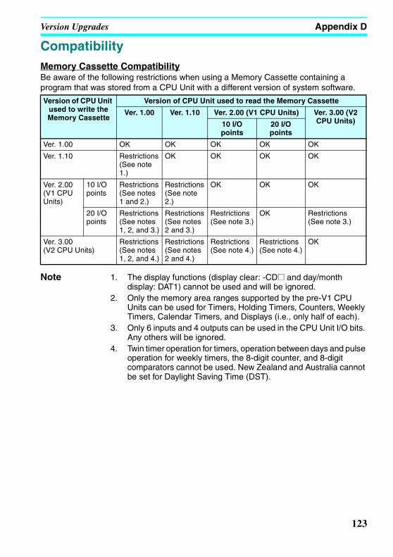
Version Upgrades Appendix D
Z234-01.book Page 123 Tuesday, September 13, 2005 5:22 PM
CompatibilityMemory Cassette CompatibilityBe aware of the following restrictions when using a Memory Cassette containing a program that was stored from a CPU Unit with a different version of system software.
Note 1. The display functions (display clear: -CD@ and day/month display: DAT1) cannot be used and will be ignored.
2. Only the memory area ranges supported by the pre-V1 CPU Units can be used for Timers, Holding Timers, Counters, Weekly Timers, Calendar Timers, and Displays (i.e., only half of each).
3. Only 6 inputs and 4 outputs can be used in the CPU Unit I/O bits. Any others will be ignored.
4. Twin timer operation for timers, operation between days and pulse operation for weekly timers, the 8-digit counter, and 8-digit comparators cannot be used. New Zealand and Australia cannot be set for Daylight Saving Time (DST).
Version of CPU Unit used to write the Memory Cassette
Version of CPU Unit used to read the Memory Cassette
Ver. 1.00 Ver. 1.10 Ver. 2.00 (V1 CPU Units) Ver. 3.00 (V2 CPU Units)10 I/O
points20 I/O points
Ver. 1.00 OK OK OK OK OK
Ver. 1.10 Restrictions (See note 1.)
OK OK OK OK
Ver. 2.00 (V1 CPU Units)
10 I/O points
Restrictions (See notes 1 and 2.)
Restrictions (See note 2.)
OK OK OK
20 I/O points
Restrictions (See notes 1, 2, and 3.)
Restrictions (See notes 2 and 3.)
Restrictions (See note 3.)
OK Restrictions (See note 3.)
Ver. 3.00 (V2 CPU Units)
Restrictions (See notes 1, 2, and 4.)
Restrictions (See notes 2 and 4.)
Restrictions (See note 4.)
Restrictions (See note 4.)
OK
123

Version Upgrades Appendix D
Z234-01.book Page 124 Tuesday, September 13, 2005 5:22 PM
Compatibility of Programs Depending on Support Software Version
Note 1. The display functions (display clear: -CD@ and day/month display: DAT1) cannot be used and will be ignored.
2. Only the memory area ranges supported by the pre-V1 CPU Units can be used for Timers, Holding Timers, Counters, Weekly Timers, Calendar Timers, and Displays (i.e., only half of each).
3. Twin timer operation for timers, operation between days and pulse operation for weekly timers, the 8-digit counter, and 8-digit comparators cannot be used. New Zealand and Australia cannot be set for Daylight Saving Time (DST).
CPU Unit system software Support Software
Ver. 1.00ZEN-SOFT01
Ver. 2.00ZEN-SOFT01-
V2
Ver. 3.00ZEN-SOFT01-
V3
Ver. 4.00ZEN-SOFT01-
V4
Ver. 1.00 OK OK Restrictions (See notes 1 and 2.)
Restrictions (See notes 1, 2, and 3.)
Ver. 1.10 Restrictions (See note 1.)
OK Restrictions (See note 2.)
Restrictions (See notes 2 and 3.)
Ver. 2.00 (V1 CPU Units)
10 I/O points Restrictions (See notes 1 and 2.)
Restrictions (See note 2.)
OK Restrictions (See note 3.)
20 I/O points Not applicable.
Not applicable.
OK Restrictions (See note 3.)
Ver. 3.00 (V2 CPU Units) Not applicable.
Not applicable.
Not applicable.
OK
124

Z234-01.book Page 125 Tuesday, September 13, 2005 5:22 PM
Appendix EApplication Examples
Lighting Pattern Control
ApplicationThe ZEN can help conserve energy if the lighting patterns required for offices and similar environments are set to the ZEN.
Use the switch operation to switch between lighting patterns.
System Configuration
Operation Switch Lighting group
1 2 3 4
(Q0) (Q1) (Q2) (Q3)
All lights ON SW 1 (I0) ON ON ON ON
Pattern 1 SW 2 (I1) ON OFF ON OFF
Pattern 2 SW 3 (I2) ON ON OFF OFF
All lights OFF SW 4 (I3) OFF OFF OFF OFF
SW1SW2SW3SW4
I0I1
I2I3
Q0 Q1 Q2 Q3
MC1 MC2 MC3 MC4
MC1 MC2
MC3 MC4
3
All lights ONPattern 1Pattern 2All lights OFF
Note: Switches use momentary normally open contacts.
Lighting group 1 (Q0) Lighting group 2 (Q1)Lighting group 1 (Q0)
Lighting group 4 (Q3)Lighting group 3 (Q2)
ZEN-10C3AR-A-V2
125

Application Examples Appendix E
Z234-01.book Page 126 Tuesday, September 13, 2005 5:22 PM
Program Example
Escalator with Automatic Operation Function (Weekly Timer, OFF Delay Timer)
ApplicationThe ZEN can be simply used to conserve energy for an escalator with an automatic operation function. The escalator can be set to operate continuously from 7:00 to 10:00 and 17:00 to 22:00 weekdays and then operate at other times and on weekends only when people approach the escalator.
System Configuration
00
01
02
03
04
05
06
07
SQ0
SQ1
SQ2
SQ3
SQ0
RQ1
SQ2
RQ3
08
09
10
11
12
13
14
15
SQ0
SQ1
RQ2
RQ3
RQ0
RQ1
RQ2
RQ3
I0 (All lights ON)Group 1 ON
Group 2 ON
Group 3 ON
Group 4 ON
Group 1 ON
Group 2 OFF
Group 3 ON
Group 4 OFF
Group 1 ON
Group 2 ON
Group 3 OFF
Group 4 OFF
Group 1 OFF
Group 2 OFF
Group 3 OFF
Group 4 OFF
I3 (All lights OFF)
I2 (Pattern 2)
I1 (Pattern 1)
COM
10C3DR-D-V2
DC12-24V
R S T200 VAC
I0
I1
I2
IMQ0
ON
OFF
DC power supply
Contactor or inverter
Escalator drive motor
Sensor to detect approaching person
Operation switchStop switch
Use two weekly timers for the 7:00 to 10:00 and 17:00 to 22:00 weekday operation.
For the rest of the time, use an OFF delay timer to operate the escalator for 3 minutes when pedestrians are detected.
ZEN-10C3DR-D-V2
126

Application Examples Appendix E
Z234-01.book Page 127 Tuesday, September 13, 2005 5:22 PM
Program Example
Parameter Settings
Water Supply Tank Control
ApplicationBasic water supply control is possible with the 61F Switch (without float) alone, however relay logic is required for inverter control of high-speed operation (when empty) and low-speed operation (when half-full).
00
01
02
03
04
05
06
@0
T0
SM0
RM0
[Q0
TT0
M0
@1
I1 Operates
I2 Stops
I0 Person detected
Escalator operates
Off delay timer startsOperates 3 minutes after person passes by the sensor.
@1 N MO-FR A
ON 17:00
OFF22:00
@1 N MO-FR A
ON 17:00
OFF22:00
Weekly timer @0(Mon to Fri: 7:00 to 10:00)
Weekly timer @1(Mon to Fri: 17:00 to 22:00)
OFF delay timer T0
127

Application Examples Appendix E
Z234-01.book Page 128 Tuesday, September 13, 2005 5:22 PM
128
System Configuration
Program Example
R S T
I0 I1I2
L1 L2N
10 11 10 11 10 11
S1S5S6
3G3FV
IM
COM
61F-GP-N (For lower limit)
61F-GP-N (For half-full)
61F-GP-N (For upper limit)
3
(200 VAC)
Inverter
Pump drive motor
Upper limit
ZEN-10C3AR-A
Half-full
Lower- limit
StopLow speed
High speed
Intermediate speed
Water storage tank
Pump
00
01
02
[Q0
[Q1
[Q2
I2 Stop (upper limit)
I0 (lower limit) I1 (intermediate)
I0 (lower limit) I1 (intermediate)
Inverter forward/stop
Inverter multistep speed command 1 (intermediate speed)
Inverter multistep speed command 2 (high speed)
Example: 3G3FV Inverter Speed
Motor speed Frequency reference 3 (high speed)Frequency
reference 2 (intermediate speed)
Frequency reference 1 (low speed)
Forward/stop (S1)
Multistep speed command 1 (S5)
Multistep speed command 2 (S6)

Application Examples Appendix E
Z234-01.book Page 129 Tuesday, September 13, 2005 5:22 PM
Greenhouse Air Circulation Control (1/3) (Bit Logic and Timer)
ApplicationThe ZEN can be used to control circulation intermittently at set times. This circulates the carbon dioxide and warm air around plants in a greenhouse.In this example, two circulation fans are operated at set intervals. The starting current is kept to a minimum and, as a result, the circulation fans are set to start operating at different times.
System Configuration
Program Example
SW1 (I0)SW2 (I1)
T1 T2
T0 T0 T0
R S T
L N
MC1 MC2
MC1 (Q0) MC2 (Q1)
IM IM
ON
OFF
3
(200 VAC)
SW1 (I0) (Operate)SW2 (I1)(Stop)
ZEN-10C3AR-A-V2
Circulation fan 1
Circulation fan 2
Circulation fan 2 (Q1)
Circulation fan 1 (Q0)
Circulation fan 1 starts operation when the operation switch is pressed. Circulation fan 2 starts operation 30 seconds later. The fans operate in a repeated cycle of 60 minutes ON, 90 minutes OFF.
M0 T1
T1
T2
T0
SM0
RM0
[Q0
TT0
[Q1
TT1
TT2
00
01
02
03
04
05
06
07
Fan 1 starts
I1 Stops
I0 Operates
Startup time offset timer
Operation timer
Fan 2 starts
Stop timer difference count
129

Application Examples Appendix E
Z234-01.book Page 130 Tuesday, September 13, 2005 5:22 PM
Parameter Settings
Greenhouse Air Circulation Control (2/3) (Calendar Timer and Weekly Timer)
ApplicationThe ZEN can be used to operate circulation fans during winter nights only.
In this example, the circulation fans operate only at night (19:00 to 6:00) during winter (November 15 to March 20).
During the operation period, the fans operate intermittently, 60 minutes ON, 30 minutes OFF. The low startup current results in a 30 second difference in the fan startup times.
The start and stop operation days during winter (November 15 and March 20) are set using the calendar timer (*0).
The start and stop operation times during the night (19:00 and 6:00) are set using the weekly timer (@0).
The startup time difference and operate/stop cycles are set using the timer (T0 to T2).
T0 X S A
TRG
RES 30.00
T1 X H:M A
TRG
RES 01.00
T2 X H:M A
TRG
RES 01.30
Offset start timer setting T0
Operation timer setting T1 Operation timer setting T2
Set to 30 seconds. Set to 1 hour. Set to 1 hour 30 seconds.
130

Application Examples Appendix E
Z234-01.book Page 131 Tuesday, September 13, 2005 5:22 PM
System Configuration
Program Example
R S T
L N
MC1 MC2
IM IM
MC1 (Q0) MC2 (Q1)
ON
OFF
3
(200 VAC)
SW1 (I0) (Operate)SW2 (I1) (Stop)
ZEN-10C3AR-A-V2
Circulation fan 1 Circulation fan 2
M0 *0 @0
M1 T1
T0
T2
T1
SM0
RM0
[M1
[Q0
TT0
[Q1
TT1
TT2
00
01
02
03
04
05
06
07
*0
Fan 1 starts
Fan 2 starts
Stop timer difference count
Startup time offset timer
Operation timer
I0 Operates
I1 Stops
131

Application Examples Appendix E
Z234-01.book Page 132 Tuesday, September 13, 2005 5:22 PM
Parameter Settings
Greenhouse Air Circulation Control (3/3) (Analog Comparator)
ApplicationThe ZEN can be used to start the circulation fans once the temperature has reached a set level. A low startup current would result from a difference in the fan startup times.
System Configuration
Set to 30 minutes.
*0 A
ON 11/15
OFF03/21
@0 N SU-SA A
ON 19:00
OFF06:00
T0 X S A
TRG
RES 30.00
T1 X H:M A
TRG
RES 01.00
T2 X M:S A
TRG
RES 30.00
Calendar Timer Setting *0
Start on Nov 15 and stop on Mar 20
Weekly timer setting @0
Start at 19:00 and stop at 6:00
Offset startup time setting T0 Operation time setting T1
Set to 30 seconds. Set to 1 hour.
Stop time setting T2
Set to 1 hour.
T0 T0
R S TI4
ON
OFF+ −
MC1 MC2
MC1 (Q0) MC2 (Q1)
IM IM
3
DC power supply Temperature
sensor (0 to 10 V)SW1 (I0) (Operate)SW2 (I1) (Stop)
ZEN-10C3DR-D-V2
Circulation fan 1
Circulation fan 2
Circulation fan 1Circulation fan 2
The temperature is detected by a 0- to 10-V temperature sensor. The circulation fans will start operation when the analog input voltage exceeds 5.2 V.
Temperature
Set temperature
Time
(200 VAC)
132

Application Examples Appendix E
Z234-01.book Page 133 Tuesday, September 13, 2005 5:22 PM
Program Example
Parameter Settings
Annunciator (Flashing Pulse Timer)
ApplicationThe ZEN can be used to make an alarm light flash when errors occur.In this example, a flashing pulse timer is used to make an alarm light flash when errors occur. Ladder programs can be created easily when a flashing pulse timer is used.
System Configuration
00
01
02
03
04
05
M0
T0
SM0
RM0
[Q0
TT0
[Q1
A0
I0 Operates
I1 Stops
Fan 1 operates
Fan 2 operates
Startup time offset timer
Analog comparator
Analog Comparator A0
Set temperature ≥ 5.2V
Offset startup timer setting T0
Set to 30 seconds.
NC
L N
L1L2/N
L1 L2 BZ
0.5 s
10C3AR-A-V2
I0: Alarm inputI1: Buzzer stop inputI2: Lamp test input
Q0: Alarm lampQ1: Normal lampQ2: Buzzer
ZEN-10C3AR-A-V2
Normal input I0
Buzzer stop I1
Lamp test I2
Alarm lamp Q0
Normal lamp Q1
Buzzer Q2
133
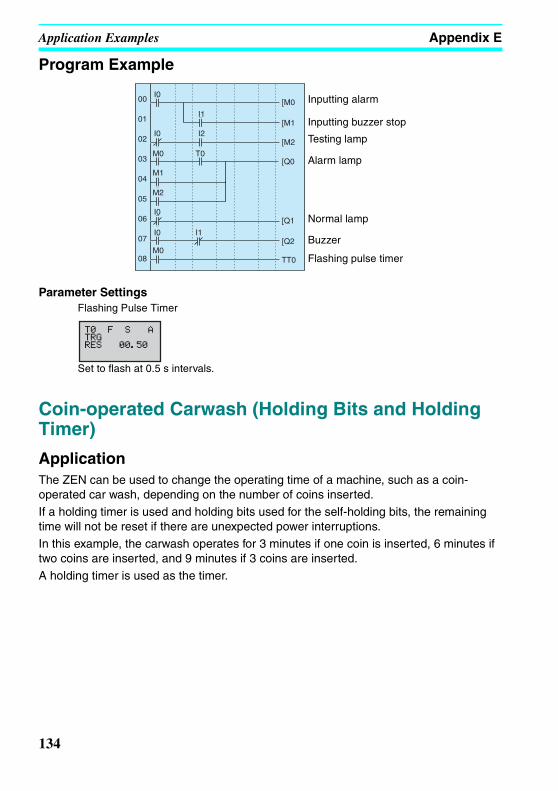
Application Examples Appendix E
Z234-01.book Page 134 Tuesday, September 13, 2005 5:22 PM
Program Example
Parameter Settings
Coin-operated Carwash (Holding Bits and Holding Timer)
ApplicationThe ZEN can be used to change the operating time of a machine, such as a coin-operated car wash, depending on the number of coins inserted.If a holding timer is used and holding bits used for the self-holding bits, the remaining time will not be reset if there are unexpected power interruptions.In this example, the carwash operates for 3 minutes if one coin is inserted, 6 minutes if two coins are inserted, and 9 minutes if 3 coins are inserted.A holding timer is used as the timer.
00
01
02
03
04
05
06
07
08
I0
I0
M0
M1
M2
I0
I0
M0
I1
[M0
[M1
[M2
[Q0
[Q1
[Q2
TT0
I1
I2
T0
Inputting alarm
Inputting buzzer stop
Testing lamp
Alarm lamp
Normal lamp
Flashing pulse timer
Buzzer
Flashing Pulse Timer
Set to flash at 0.5 s intervals.
134

Application Examples Appendix E
Z234-01.book Page 135 Tuesday, September 13, 2005 5:22 PM
System Configuration
Program Example
Parameter Settings
NC
100 I0
Q0
Q0
I0
10C3AR-A-V2
Coin selector
Carwash operation
ZEN-10C3AR-A-V2
3 min 9 min
00
01
02
03
04
05
06
07
08
09
10
11
I0 H0
M0
M0
H0
H0
M1
M1
H1
H1
M2
M2
H2
I0 M3
I0 H1
I0 M4
I0
I0
H2
M5
[M0
[H0
[M1
[H1
[M2
[H2
12
13
14
15
16
17
18
19
20
H0
H1
H2
#0
M3
M4
M5
H0 H1
H1 H2
H2
[Q0
T#0
[M3
[M4
[M5
R#0
Insertion of 1st coin detected
Insertion of 2nd coin detected
Insertion of 3rd coin detected
Carwash drive output
Holding timer startup
Self-holding for 1st coin cleared
Self-holding for 2nd coin clearedSelf-holding for 3rd coin clearedHolding timer reset
Holding Timer
Set to 3 minutes.
135

Application Examples Appendix E
Z234-01.book Page 136 Tuesday, September 13, 2005 5:22 PM
Warming Molding Machines (Weekly Timer and Bit Logic)
ApplicationThe ZEN can be used to improve molding efficiency by warming up the molding machine before the work shift starts. This allows molding work to begin immediately at the start of the work shift.When work shifts vary, pre-set weekly timers can be selected using a switch.
System Configuration
NC
10C3AR-A-V2
SW1 (I0) (Continuous operation)SW2 (I1) (Pattern 1)SW3 (I2) (Pattern 2)SW4 (I3) (Pattern 3)SW5 (I4) (Stop)
ZEN-10C3AR-A-V2
Molding machine heating circuit
Q0
136

Application Examples Appendix E
Z234-01.book Page 137 Tuesday, September 13, 2005 5:22 PM
Program Example
Parameter Settings
00
01
02
03
04
05
06
07
08
09
10
11
12
13
14
I1
I2
I3
RM0
SM1
RM2
RM3
RM4
RM0
RM1
SM2
RM3
RM4
RM0
RM1
RM2
SM3
RM4
15
16
17
18
19
20
21
22
23
24
25
I4
I0
M1
M2
M3
M0
@0
@1
@2
RM0
RM1
RM2
RM3
RM4
SM0
[Q0
Pattern 1 selected
Pattern 2 selected
Pattern 3 selected
Stops
Operates
Switches operation pattern
Weekly Timer Setting @0 to @2
137

Application Examples Appendix E
Z234-01.book Page 138 Tuesday, September 13, 2005 5:22 PM
138

Z234-01.book Page 139 Tuesday, September 13, 2005 5:22 PM
Appendix FAllocations and Setting Table
I/O Allocations for the ZEN-10C3@R-@-V2I/O Unit name Bit Input device name Input IN filter
Input bits
CPU Unit I0 AC DC V Yes NoI1I2I3I4 Normal input AC DC V Yes No
Analog voltage inputI5 Normal input
Analog voltage input
I/O Unit name Bit Output device name and specificationsOutput bits
CPU Unit Q0 AC DC V AQ1 AC DC V AQ2 AC DC V AQ3* AC DC V A
CPU Unit IN I0 to I5
CPU Unit OUT Q0 to Q3
3
139

Allocations and Setting Table Appendix F
Z234-01.book Page 140 Tuesday, September 13, 2005 5:22 PM
Work and Holding Bit Allocations
Timer and Holding Timer Settings
Note X: ON delay; : OFF delay; O: One-shot pulse; F: Flashing pulse; W: Twin timer
Bit type Address Application Bit type Address ApplicationWork bits M0 Holding
bitsH0
M1 H1M2 H2M3 H3M4 H4M5 H5M6 H6M7 H7M8 H8M9 H9Ma HaMb HbMc HcMd HdMe HeMf Hf
Timer Address Operation setting
(See note.)
Setting time unit 1
Setting time unit 2
(W only)
Set time Application
Timer T0 X O F W H:M M:S S H:M M:S ST1 X O F W H:M M:S S H:M M:S ST2 X O F W H:M M:S S H:M M:S ST3 X O F W H:M M:S S H:M M:S ST4 X O F W H:M M:S S H:M M:S ST5 X O F W H:M M:S S H:M M:S ST6 X O F W H:M M:S S H:M M:S ST7 X O F W H:M M:S S H:M M:S ST8 X O F W H:M M:S S H:M M:S ST9 X O F W H:M M:S S H:M M:S STa X O F W H:M M:S S H:M M:S STb X O F W H:M M:S S H:M M:S STc X O F W H:M M:S S H:M M:S STd X O F W H:M M:S S H:M M:S STe X O F W H:M M:S S H:M M:S STf X O F W H:M M:S S H:M M:S S
Holding timer #0 X H:M M:S S ---#1 X H:M M:S S#2 X H:M M:S S#3 X H:M M:S S#4 X H:M M:S S#5 X H:M M:S S#6 X H:M M:S S#7 X H:M M:S S ---
140

Allocations and Setting Table Appendix F
Z234-01.book Page 141 Tuesday, September 13, 2005 5:22 PM
Counter SettingsCounter address
Setting (No. of times)
Application
C0 Incrementing:Decrementing:Reset:
C1 Incrementing:Decrementing:Reset:
C2 Incrementing:Decrementing:Reset:
C3 Incrementing:Decrementing:Reset:
C4 Incrementing:Decrementing:Reset:
C5 Incrementing:Decrementing:Reset:
C6 Incrementing:Decrementing:Reset:
C7 Incrementing:Decrementing:Reset:
C8 Incrementing:Decrementing:Reset:
C9 Incrementing:Decrementing:Reset:
Ca Incrementing:Decrementing:Reset:
Cb Incrementing:Decrementing:Reset:
Cc Incrementing:Decrementing:Reset:
Cd Incrementing:Decrementing:Reset:
Ce Incrementing:Decrementing:Reset:
Cf Incrementing:Decrementing:Reset:
141
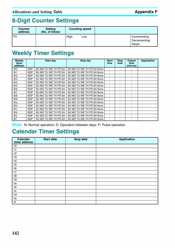
Allocations and Setting Table Appendix F
Z234-01.book Page 142 Tuesday, September 13, 2005 5:22 PM
8-Digit Counter Settings
Weekly Timer Settings
Note N: Normal operation; D: Operation between days; P: Pulse operation
Calendar Timer Settings
Counter address
Setting(No. of times)
Counting speed
F0 High Low Incrementing:Decrementing:Reset:
Weekly timer
address
Start day Stop day Start time
Stop time
Output time
(mm:ss)
Application
@0 NDP SU MO TU WE TH FR SA SU MO TU WE TH FR SA None : : :@1 NDP SU MO TU WE TH FR SA SU MO TU WE TH FR SA None : : :@2 NDP SU MO TU WE TH FR SA SU MO TU WE TH FR SA None : : :@3 NDP SU MO TU WE TH FR SA SU MO TU WE TH FR SA None : : :@4 NDP SU MO TU WE TH FR SA SU MO TU WE TH FR SA None : : :@5 NDP SU MO TU WE TH FR SA SU MO TU WE TH FR SA None : : :@6 NDP SU MO TU WE TH FR SA SU MO TU WE TH FR SA None : : :@7 NDP SU MO TU WE TH FR SA SU MO TU WE TH FR SA None : : :@8 NDP SU MO TU WE TH FR SA SU MO TU WE TH FR SA None : : :@9 NDP SU MO TU WE TH FR SA SU MO TU WE TH FR SA None : : :@a NDP SU MO TU WE TH FR SA SU MO TU WE TH FR SA None : : :@b NDP SU MO TU WE TH FR SA SU MO TU WE TH FR SA None : : :@c NDP SU MO TU WE TH FR SA SU MO TU WE TH FR SA None : : :@d NDP SU MO TU WE TH FR SA SU MO TU WE TH FR SA None : : :@e NDP SU MO TU WE TH FR SA SU MO TU WE TH FR SA None : : :@f NDP SU MO TU WE TH FR SA SU MO TU WE TH FR SA None : : :
Calendar timer address
Start date Stop date Application
*0*1*2*3*4*5*6*7*8*9*a*b*c*d*e*f
142
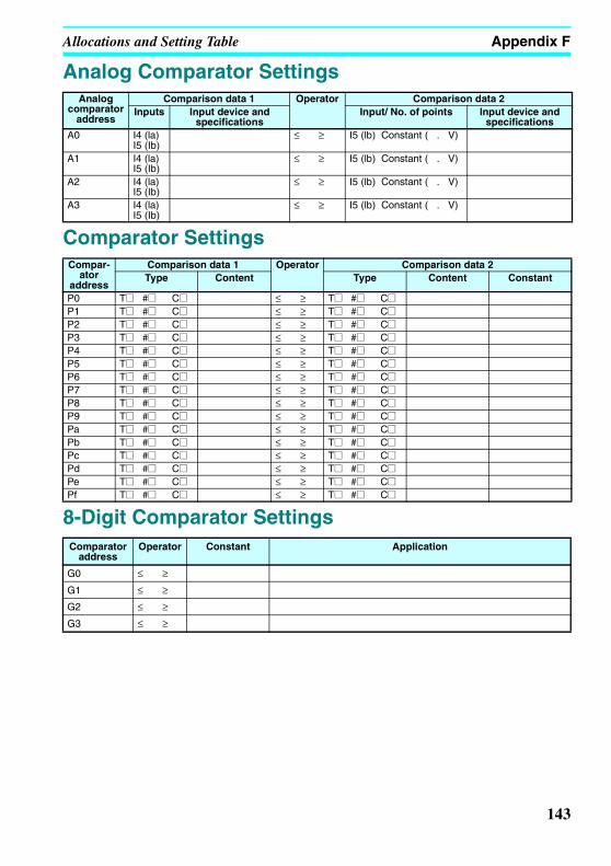
Allocations and Setting Table Appendix F
Z234-01.book Page 143 Tuesday, September 13, 2005 5:22 PM
Analog Comparator Settings
Comparator Settings
8-Digit Comparator Settings
Analog comparator
address
Comparison data 1 Operator Comparison data 2Inputs Input device and
specificationsInput/ No. of points Input device and
specificationsA0 I4 (la)
I5 (Ib)≤ ≥ I5 (lb) Constant ( . V)
A1 I4 (la) I5 (Ib)
≤ ≥ I5 (lb) Constant ( . V)
A2 I4 (la) I5 (Ib)
≤ ≥ I5 (lb) Constant ( . V)
A3 I4 (la) I5 (Ib)
≤ ≥ I5 (lb) Constant ( . V)
Compar-ator
address
Comparison data 1 Operator Comparison data 2Type Content Type Content Constant
P0 T@ #@ C@ ≤ ≥ T@ #@ C@P1 T@ #@ C@ ≤ ≥ T@ #@ C@P2 T@ #@ C@ ≤ ≥ T@ #@ C@P3 T@ #@ C@ ≤ ≥ T@ #@ C@P4 T@ #@ C@ ≤ ≥ T@ #@ C@P5 T@ #@ C@ ≤ ≥ T@ #@ C@P6 T@ #@ C@ ≤ ≥ T@ #@ C@P7 T@ #@ C@ ≤ ≥ T@ #@ C@P8 T@ #@ C@ ≤ ≥ T@ #@ C@P9 T@ #@ C@ ≤ ≥ T@ #@ C@Pa T@ #@ C@ ≤ ≥ T@ #@ C@Pb T@ #@ C@ ≤ ≥ T@ #@ C@Pc T@ #@ C@ ≤ ≥ T@ #@ C@Pd T@ #@ C@ ≤ ≥ T@ #@ C@Pe T@ #@ C@ ≤ ≥ T@ #@ C@Pf T@ #@ C@ ≤ ≥ T@ #@ C@
Comparator address
Operator Constant Application
G0 ≤ ≥
G1 ≤ ≥
G2 ≤ ≥
G3 ≤ ≥
143

Allocations and Setting Table Appendix F
Z234-01.book Page 144 Tuesday, September 13, 2005 5:22 PM
Display Function SettingsDisplay bit
addressBacklight/Display function display screen switching
Display start position
Display message Application
D0 L0 L1 L2 L3 X: Y:D1 L0 L1 L2 L3 X: Y:D2 L0 L1 L2 L3 X: Y:D3 L0 L1 L2 L3 X: Y:D4 L0 L1 L2 L3 X: Y:D5 L0 L1 L2 L3 X: Y:D6 L0 L1 L2 L3 X: Y:D7 L0 L1 L2 L3 X: Y:D8 L0 L1 L2 L3 X: Y:D9 L0 L1 L2 L3 X: Y:Da L0 L1 L2 L3 X: Y:Db L0 L1 L2 L3 X: Y:Dc L0 L1 L2 L3 X: Y:Dd L0 L1 L2 L3 X: Y:De L0 L1 L2 L3 X: Y:Df L0 L1 L2 L3 X: Y:
Backlight Display function display screen switching CHR Characters (12 digits max.)L0 No No DAT Month/day (5 digits: @@/@@)L1 Yes No DAT1 Day/month (5 digits: @@/@@)L2 No Yes CLK Hour:minutes (5 digits: @@:@@)L3 Yes Yes I4/I5 Analog conversion (4 digits: @@.@)
T0 to Tf Timer present value (5 digits: @@.@@)
#0 to #7 Holding timer present value (5 digits: @@.@@)
C0 to Cf Counter present value (4 digits: @@@@)
F0 8-Digit counter present value(8 digits: @@@@@@@@)
144

Z234-01.book Page 145 Tuesday, September 13, 2005 5:22 PM
Index
A-Badditional functions for bit outputs 21, 51allocations
allocation tables 139I/O allocations 24, 139
alternate operation 4, 22, 51analog inputs 74application
examples 125–137available models 9backlight
changing automatic cutout time 92Battery Unit
mounting 96blank lines
deleting 59button switches 12
using 85
Ccalendar timers 72characteristics 107CLOCK 44comparators
addresses 50analog 74comparing present values 77, 80
conduit installation 30connection lines 53
deleting 58counters
addresses 22, 50, 52comparing values 77, 80using 64
CPU Unitsavailable models 9specifications 108, 110
Ddate
setting 44Daylight Saving Time (DST)
setting 93dimensions 111DIN track 25
mounting 28display bits
addresses 23, 52displaying messages 82
display language 43display screen 11duct installation 29
E-Herror messages
deleting 104meaning 102
false inputs 36features 8flashing pulse timer 61holding timers 60
II/O bits
allocation 24inductive loads 37, 38input devices
connecting 35inputs
analog 74changing 57deleting 58input bits 21input filter 90stabilizing input operations 90wiring input lines 31
145

Index
Z234-01.book Page 146 Tuesday, September 13, 2005 5:22 PM
writing 49inrush current
suppressing 39installation 28internal holding bits 21
LLadder Program Edit Screen settings
analog inputs 75calendar timers 72comparing present values 77, 80counters 64display bits 82timers and holding timers 62weekly timers 68
ladder programsSee programs
languageselecting display language 43
leakage current 36limit switches
preventing false inputs 36lines
inserting 58
Mmemory
memory areas 21, 50, 51Memory Cassettes 9
mounting 97transferring programs 98
MONITOR 56mounting 28
Battery Units 96
OOFF delay timer 60ON delay timer 60one-shot pulse timer 61operating mode 56
RUN mode 13, 14STOP mode 13, 14
operationconfirming 55preparation 25
operation buttons 12optional products 10outputs
changing additional bit output functions 57deleting 58output bits 21wiring output circuits 38writing 50
PPARAMETER 14Parameter Monitor Screen Display
analog comparators 76calendar timers 73comparing present values 79, 81counters 66timers and holding timers 63weekly timers 71
Parameter Settings Screen settingsanalog comparators 76calendar timers 72comparing present values 78, 80counters 65display bits 83timers and holding timers 62weekly timers 69
passworddeleting 89setting 89
photoelectric switchespreventing false inputs 36
power cables 29power supply
wiring 31Programming Device
available models 10programs
clearing 46correcting 57creating 46examples 125
146

Index
Z234-01.book Page 147 Tuesday, September 13, 2005 5:22 PM
executing 113execution time 114protecting 88writing 47
proximity switchespreventing false inputs 36
R-Sreset input 62, 64reset operation 22, 51set operation 22, 51settings
setting sheets 139specifications
general 105, 106input 108output 110
Support Software 3connecting 99
switching capacity 110system configuration 8
system informationreading 94
T-Wtime
setting 44timers 60
addresses 22, 50, 52calendar timers 72comparing values 77, 80flashing pulse timer 61OFF delay timer 60ON delay timer 60one-shot pulse timer 61twin timer 61weekly timers 67
trigger input 60troubleshooting 102weekly timers 67wiring 29
I/O 46work bits 21
147

Index
Z234-01.book Page 148 Tuesday, September 13, 2005 5:22 PM
148

Z234-01.book Page 149 Tuesday, September 13, 2005 5:22 PM
Revision History
A manual revision code appears as a suffix to the catalog number on the front cover ofthe manual.
The following table outlines the changes made to the manual during each revision. Pagenumbers refer to the previous version.
Revision code
Date Revised content
01 August 2005 Original production (for ZEN-10C3@R-@-V2 models)
Cat. No. Z234-E1-01
Revision code
149

Z234-01.book Page 150 Tuesday, September 13, 2005 5:22 PM

Terms and Conditions of Sale1. Offer; Acceptance. These terms and conditions (these "Terms") are deemed
part of all quotes, agreements, purchase orders, acknowledgments, price lists,catalogs, manuals, brochures and other documents, whether electronic or inwriting, relating to the sale of products or services (collectively, the "Products")by Omron Electronics LLC and its subsidiary companies (“Omron”). Omronobjects to any terms or conditions proposed in Buyer’s purchase order or otherdocuments which are inconsistent with, or in addition to, these Terms.
2. Prices; Payment Terms. All prices stated are current, subject to change with-out notice by Omron. Omron reserves the right to increase or decrease priceson any unshipped portions of outstanding orders. Payments for Products aredue net 30 days unless otherwise stated in the invoice.
3. Discounts. Cash discounts, if any, will apply only on the net amount of invoicessent to Buyer after deducting transportation charges, taxes and duties, and willbe allowed only if (i) the invoice is paid according to Omron’s payment termsand (ii) Buyer has no past due amounts.
4. Interest. Omron, at its option, may charge Buyer 1-1/2% interest per month orthe maximum legal rate, whichever is less, on any balance not paid within thestated terms.
5. Orders. Omron will accept no order less than $200 net billing. 6. Governmental Approvals. Buyer shall be responsible for, and shall bear all
costs involved in, obtaining any government approvals required for the impor-tation or sale of the Products.
7. Taxes. All taxes, duties and other governmental charges (other than generalreal property and income taxes), including any interest or penalties thereon,imposed directly or indirectly on Omron or required to be collected directly orindirectly by Omron for the manufacture, production, sale, delivery, importa-tion, consumption or use of the Products sold hereunder (including customsduties and sales, excise, use, turnover and license taxes) shall be charged toand remitted by Buyer to Omron.
8. Financial. If the financial position of Buyer at any time becomes unsatisfactoryto Omron, Omron reserves the right to stop shipments or require satisfactorysecurity or payment in advance. If Buyer fails to make payment or otherwisecomply with these Terms or any related agreement, Omron may (without liabil-ity and in addition to other remedies) cancel any unshipped portion of Prod-ucts sold hereunder and stop any Products in transit until Buyer pays allamounts, including amounts payable hereunder, whether or not then due,which are owing to it by Buyer. Buyer shall in any event remain liable for allunpaid accounts.
9. Cancellation; Etc. Orders are not subject to rescheduling or cancellationunless Buyer indemnifies Omron against all related costs or expenses.
10. Force Majeure. Omron shall not be liable for any delay or failure in deliveryresulting from causes beyond its control, including earthquakes, fires, floods,strikes or other labor disputes, shortage of labor or materials, accidents tomachinery, acts of sabotage, riots, delay in or lack of transportation or therequirements of any government authority.
11. Shipping; Delivery. Unless otherwise expressly agreed in writing by Omron:a. Shipments shall be by a carrier selected by Omron; Omron will not drop ship
except in “break down” situations.b. Such carrier shall act as the agent of Buyer and delivery to such carrier shall
constitute delivery to Buyer;c. All sales and shipments of Products shall be FOB shipping point (unless oth-
erwise stated in writing by Omron), at which point title and risk of loss shallpass from Omron to Buyer; provided that Omron shall retain a security inter-est in the Products until the full purchase price is paid;
d. Delivery and shipping dates are estimates only; ande. Omron will package Products as it deems proper for protection against nor-
mal handling and extra charges apply to special conditions.12. Claims. Any claim by Buyer against Omron for shortage or damage to the
Products occurring before delivery to the carrier must be presented in writingto Omron within 30 days of receipt of shipment and include the original trans-portation bill signed by the carrier noting that the carrier received the Productsfrom Omron in the condition claimed.
13. Warranties. (a) Exclusive Warranty. Omron’s exclusive warranty is that theProducts will be free from defects in materials and workmanship for a period oftwelve months from the date of sale by Omron (or such other period expressedin writing by Omron). Omron disclaims all other warranties, express or implied.(b) Limitations. OMRON MAKES NO WARRANTY OR REPRESENTATION,EXPRESS OR IMPLIED, ABOUT NON-INFRINGEMENT, MERCHANTABIL-
ITY OR FITNESS FOR A PARTICULAR PURPOSE OF THE PRODUCTS.BUYER ACKNOWLEDGES THAT IT ALONE HAS DETERMINED THAT THEPRODUCTS WILL SUITABLY MEET THE REQUIREMENTS OF THEIRINTENDED USE. Omron further disclaims all warranties and responsibility ofany type for claims or expenses based on infringement by the Products or oth-erwise of any intellectual property right. (c) Buyer Remedy. Omron’s sole obli-gation hereunder shall be, at Omron’s election, to (i) replace (in the formoriginally shipped with Buyer responsible for labor charges for removal orreplacement thereof) the non-complying Product, (ii) repair the non-complyingProduct, or (iii) repay or credit Buyer an amount equal to the purchase price ofthe non-complying Product; provided that in no event shall Omron be responsi-ble for warranty, repair, indemnity or any other claims or expenses regardingthe Products unless Omron’s analysis confirms that the Products were prop-erly handled, stored, installed and maintained and not subject to contamina-tion, abuse, misuse or inappropriate modification. Return of any Products byBuyer must be approved in writing by Omron before shipment. Omron Compa-nies shall not be liable for the suitability or unsuitability or the results from theuse of Products in combination with any electrical or electronic components,circuits, system assemblies or any other materials or substances or environ-ments. Any advice, recommendations or information given orally or in writing,are not to be construed as an amendment or addition to the above warranty.See http://oeweb.omron.com or contact your Omron representative for pub-lished information.
14. Limitation on Liability; Etc. OMRON COMPANIES SHALL NOT BE LIABLEFOR SPECIAL, INDIRECT, INCIDENTAL, OR CONSEQUENTIAL DAMAGES,LOSS OF PROFITS OR PRODUCTION OR COMMERCIAL LOSS IN ANYWAY CONNECTED WITH THE PRODUCTS, WHETHER SUCH CLAIM ISBASED IN CONTRACT, WARRANTY, NEGLIGENCE OR STRICT LIABILITY.Further, in no event shall liability of Omron Companies exceed the individualprice of the Product on which liability is asserted.
15. Indemnities. Buyer shall indemnify and hold harmless Omron Companies andtheir employees from and against all liabilities, losses, claims, costs andexpenses (including attorney's fees and expenses) related to any claim, inves-tigation, litigation or proceeding (whether or not Omron is a party) which arisesor is alleged to arise from Buyer's acts or omissions under these Terms or inany way with respect to the Products. Without limiting the foregoing, Buyer (atits own expense) shall indemnify and hold harmless Omron and defend or set-tle any action brought against such Companies to the extent based on a claimthat any Product made to Buyer specifications infringed intellectual propertyrights of another party.
16. Property; Confidentiality. Any intellectual property in the Products is the exclu-sive property of Omron Companies and Buyer shall not attempt to duplicate itin any way without the written permission of Omron. Notwithstanding anycharges to Buyer for engineering or tooling, all engineering and tooling shallremain the exclusive property of Omron. All information and materials suppliedby Omron to Buyer relating to the Products are confidential and proprietary,and Buyer shall limit distribution thereof to its trusted employees and strictlyprevent disclosure to any third party.
17. Export Controls. Buyer shall comply with all applicable laws, regulations andlicenses regarding (i) export of products or information; (iii) sale of products to“forbidden” or other proscribed persons; and (ii) disclosure to non-citizens ofregulated technology or information.
18. Miscellaneous. (a) Waiver. No failure or delay by Omron in exercising any rightand no course of dealing between Buyer and Omron shall operate as a waiverof rights by Omron. (b) Assignment. Buyer may not assign its rights hereunderwithout Omron's written consent. (c) Law. These Terms are governed by thelaw of the jurisdiction of the home office of the Omron company from whichBuyer is purchasing the Products (without regard to conflict of law princi-ples). (d) Amendment. These Terms constitute the entire agreement betweenBuyer and Omron relating to the Products, and no provision may be changedor waived unless in writing signed by the parties. (e) Severability. If any provi-sion hereof is rendered ineffective or invalid, such provision shall not invalidateany other provision. (f) Setoff. Buyer shall have no right to set off any amountsagainst the amount owing in respect of this invoice. (g) Definitions. As usedherein, “including” means “including without limitation”; and “Omron Compa-nies” (or similar words) mean Omron Corporation and any direct or indirectsubsidiary or affiliate thereof.
Certain Precautions on Specifications and Use1. Suitability of Use. Omron Companies shall not be responsible for conformity
with any standards, codes or regulations which apply to the combination of theProduct in the Buyer’s application or use of the Product. At Buyer’s request,Omron will provide applicable third party certification documents identifyingratings and limitations of use which apply to the Product. This information byitself is not sufficient for a complete determination of the suitability of the Prod-uct in combination with the end product, machine, system, or other applicationor use. Buyer shall be solely responsible for determining appropriateness ofthe particular Product with respect to Buyer’s application, product or system.Buyer shall take application responsibility in all cases but the following is anon-exhaustive list of applications for which particular attention must be given:(i) Outdoor use, uses involving potential chemical contamination or electricalinterference, or conditions or uses not described in this document.(ii) Use in consumer products or any use in significant quantities. (iii) Energy control systems, combustion systems, railroad systems, aviationsystems, medical equipment, amusement machines, vehicles, safety equip-ment, and installations subject to separate industry or government regulations. (iv) Systems, machines and equipment that could present a risk to life or prop-erty. Please know and observe all prohibitions of use applicable to this Prod-uct. NEVER USE THE PRODUCT FOR AN APPLICATION INVOLVING SERIOUSRISK TO LIFE OR PROPERTY OR IN LARGE QUANTITIES WITHOUTENSURING THAT THE SYSTEM AS A WHOLE HAS BEEN DESIGNED TO
ADDRESS THE RISKS, AND THAT THE OMRON’S PRODUCT IS PROP-ERLY RATED AND INSTALLED FOR THE INTENDED USE WITHIN THEOVERALL EQUIPMENT OR SYSTEM.
2. Programmable Products. Omron Companies shall not be responsible for theuser’s programming of a programmable Product, or any consequence thereof.
3. Performance Data. Data presented in Omron Company websites, catalogsand other materials is provided as a guide for the user in determining suitabil-ity and does not constitute a warranty. It may represent the result of Omron’stest conditions, and the user must correlate it to actual application require-ments. Actual performance is subject to the Omron’s Warranty and Limitationsof Liability.
4. Change in Specifications. Product specifications and accessories may bechanged at any time based on improvements and other reasons. It is our prac-tice to change part numbers when published ratings or features are changed,or when significant construction changes are made. However, some specifica-tions of the Product may be changed without any notice. When in doubt, spe-cial part numbers may be assigned to fix or establish key specifications foryour application. Please consult with your Omron’s representative at any timeto confirm actual specifications of purchased Product.
5. Errors and Omissions. Information presented by Omron Companies has beenchecked and is believed to be accurate; however, no responsibility is assumedfor clerical, typographical or proofreading errors or omissions.

Z234-E1-01 10/06 ©2006 OMRON ELECTRONICS LLC Specifications subject to change without notice.Printed in the U.S.A.
OMRON ELECTRONICS LLC
1 Commerce DriveSchaumburg, IL 60173847.843.7900For US technical support or other inquiries: 800.556.6766
OMRON CANADA, INC.885 Milner AvenueToronto, Ontario M1B 5V8416.286.6465
OMRON ON-LINEGlobal - http://www.omron.comUSA -http://www.omron.com/oeiCanada -http://www.omron.ca