3, issue 10, february 2018 a study on design of vibratory ... · this paper presents an approach to...
TRANSCRIPT

International Journal of Advanced Engineering Research and Applications (IJA-ERA) ISSN: 2454-2377
Volume – 3, Issue – 10, February – 2018
www.ijaera.org 2018, IJA-ERA - All Rights Reserved 383
A Study on Design of Vibratory Apparatus
and Experimental Validation on Hard Boring
with Ultrasonic-Assisted Cutting
Quoc-Huy Ngo1, Ngoc-Hung Chu2, Van-Du Nguyen3*
1Faculty of Mechanical Engineering, Thai Nguyen University of Technology
Thai Nguyen, Viet Nam, E-mail: [email protected]
2Faculty of International Training, Thai Nguyen University of Technology
Thai Nguyen, Viet Nam, E-mail: [email protected]
3Faculty of Mechanical Engineering, Thai Nguyen University of Technology,
Thai Nguyen, Viet Nam, E-mail: [email protected]*
Abstract: Ultrasonic-Assisted Machining has been proved to be superior to conventional machining,
especially for difficult-to-cut materials. This paper presents a design approach for the vibratory
apparatus which can be applied to vibration assisted boring (UAB) process, a special case of hard-
machining used to make holes by internal turning. In cases of making conical holes with UAB on
conventional lathes, it would be more convenient to employ the available tool post and the
compound rest instead of using additional attachments. However, the ultrasonic actuator usually has
large dimensions, making it impossible to arrange the tool jig, including ultrasonic actuator, on the
compound rest of conventional lathes. The vibratory unit proposed in this paper can address this
issue. An experimental study was also implemented to validate the ability of the new tool holder in
practical work. A set of 20 sample holes made from Cr12Mo die-steel, hardened with HRC 62-64,
has been machined under both conventional boring (CB) and ultrasonic assisted boring (UAB).
Taguchi design of experiments and analysis technique have been employed to evaluate advantages of
Ultrasonic Assisted Boring compared to conventional boring. It has been shown that, with a
confident of 95%, the surface roughness values of the machined holes with UAB reduced as high as
50%, compared to CB. It has been found that the high precision boring can be realized by means of
this new design which is convenient for conventional lathes. The results would play an important
role in the development of design and manufacture of complete tools for vibration assistance
machining for difficult-to-cut materials.
Keywords: Vibration Assisted Machining, Boring, Hard-Turning, Hardened Die Steel
I. INTRODUCTION
Ultrasonic assisted machining (UAM) is a technique in which vibrations with small-amplitude, high-
frequency is superimposed to the relative motion between cutting tool and workpiece during the
machining operation to achieve better cutting performance [1]. Numerous advantages of UAM over
conventional machining have been observed as reducing cutting force [2 & 3], generating thinner
chips, which in turn leads to improved surface finishes and better form accuracy [4-6], and extended
tool life [8-10].

International Journal of Advanced Engineering Research and Applications
(IJA-ERA)
Volume – 3, Issue – 10
February – 2018
www.ijaera.org 2018, IJA-ERA - All Rights Reserved 384
Ultrasonic assistant technique has been applied to various non-conventional and conventional
manufacturing processes, such as Micro-EDM, laser machining, abrasive machining, grinding,
milling, drilling, and turning [1 & 10].
In machining, boring is the process of enlarging a hole that has already been drilled (or cast) by
means of a single-point cutting tool. Boring is usually used to achieve greater accuracy of holes and
can be used to cut conical holes. It has been found that, among several manufacturing processes,
turning is an attracted field of UAM applications. Ultrasonic assisted turning (UAT) has been found
to be very effective in machining of high strength alloys and other difficult-to-cut materials [1-5, 7-9,
10, 11]. For finishing operations, one of the most important effects of UAT is the improvement in
term of surface roughness compared to CT. A poor surface finish of the machined part results in high
cost post finishing operations. Surface quality is also an important parameter which is directly related
to the fatigue life of the produced component [12].
Despite abundant studies have been focused on ultrasonic assisted turning, applications of Ultrasonic
Assisted Boring (UAB) appeared to be limited in literatures. In previous applications of UAT and
UAB, the vibratory unit usually occupied the place of the conventional tool post.
Figure 1. A proposed arrangement of the vibratory unit on the tool post
This paper presents an approach to design a vibratory rig with boring tool and combined within a jig
which can be clamped on the tool post of conventional lathes, as depicted in Figure 1. If the vibratory
is clamped on the tool post, operation of boring a conical hole would be much convenient with the
support from the hand feeding (See Figure 1). Design each part of the whole setup will be presented
in next sections. The vibratory apparatus has been experimentally validated via practical boring of
hardened die-steel samples.
II. DESIGN AND ANALYSIS OF THE VIBRATORY RIG
A. Basic of the new design
In this study, a commercial ultrasonic transducer working with frequency of 20 kHz and a stepped
horn were selected. Figure 2 depicts the proposed system for the study. Ultrasonic vibration, induced
at the end A1 of the ultrasonic transducer (1), is transferred and enlarged via the horn (2). The
amplified vibration obtained at the end A2 of the horn is then transmitted to the cutting edge A3 of
the boring tool (5) by the clamping tube (3) and screw (4). Design and test the horn and other part of
the tool jig are the objectives of this paper.

International Journal of Advanced Engineering Research and Applications
(IJA-ERA)
Volume – 3, Issue – 10
February – 2018
www.ijaera.org 2018, IJA-ERA - All Rights Reserved 385
The design calculation for dimensions (diameters and lengths) of the ultrasonic horn can be carried
out by using theory of stepped cylindrical ultrasonic horn with half-wave length principle, which
have been well known in several literatures (See for example in [2-6,14,15]). The basic calculation is
briefly described as below.
Figure 2. Experimental tool holder schema
Assigning for the wavelength of the ultrasonic wave, f for the frequency of vibration, c for the sound
velocity, = 2πf for the angular frequency; E for Young's modulus of elasticity, for the density of
material of the horn; S1, Sx,S2 is cross-sectional area of the horn at x=0 (at plane A1), x and x=L (at
plane A2) – see Figure 3 for more details.
Figure 3. Parameters for calculation of the horn dimensions
The longitudinal transmission velocity, c and wavelength of the ultrasonic wave in 1D continuum,
can be calculated as:

International Journal of Advanced Engineering Research and Applications
(IJA-ERA)
Volume – 3, Issue – 10
February – 2018
www.ijaera.org 2018, IJA-ERA - All Rights Reserved 386
/c E (1)
/c f (2)
The basic horn equations for particle displacement, u can be expressed:
- In case x ≤ /4, the displacement, ux , is:
1.cos . os( )x
xu u c t
c
(3)
- In case /4 < x ≤ /2, the displacement, ux , is:
2
( ).cos . os( )x
L xu u c t
c
(4)
It is important to determine the location to clamp the ultrasonic system on machines, which is called
"nodal plane". The nodal plane location is the position where particle displacement is zero (unode = 0)
can be taken from the following equation:
.cos 0nodex
c
or
4node
ncx
f (5)
where n is an odd number. For a stepped horn expected to have one node, n = 1, so xnode = /4. The
amplification factor, G, for the half-wave stepped horn is determined by:
2
2 1 1
1 2 2
u S DG
u S D
(6)
where D1, D2 are diameters of the larger and the smaller ends of the horn, respectively.
B. Design of the horn
1) Ininital design
The basic Equations above can be used to initially determine dimensions of a single stepped horn. In
this study, aluminum alloy Al7075 is selected as the material of the horn. The material has the
following characteristics: elastic modulus E=71.7 GPa; density =2810 kg/m3, sound velocity c=5051
m/s, Poisson's ratio µ = 0.33.
Firstly, the resonant length of the stepped shaped horn can be obtained as [14,15]:
1 24 4
c cL k k
f f (7)
To simplify the calculation, the correction factors k1 and k2 are assumed to be unity. Hence, for the
working frequency of 20 kHz, the total length of the horn is initially chosen as L=/2126 mm by

International Journal of Advanced Engineering Research and Applications
(IJA-ERA)
Volume – 3, Issue – 10
February – 2018
www.ijaera.org 2018, IJA-ERA - All Rights Reserved 387
applying Equations (1) and (2). As a result, the nodal plane should be placed in the middle of the horn,
at /463 mm.
Secondly, the diameter of the large end of the horn was designed as D1=50 mm, corresponding to the
diameter of the transducer end. The diameter of the small end of the horn was chosen as D2=30 mm to
satisfy the requirement of making a hole for tool clamping. As a result, the amplification factor of the
horn is of G= (50/30)22.8, strong enough as normal ultrasonic applications in metal cutting.
2) Refine the design
The calculated values above are carried out for a horn with two cylindrical steps, without nodal flange
and any other structures required to hold the boring tool. It has been well known that, any changes in
size, shape, and structure of the horn can affect the resonant frequency of the ultrasonic vibrator [14].
To avoid wasting material and designing time, the vibratory system should be tested via simulation,
based on Finite Element Analysis (FEA) technique, until the desired results are achieved. A basic
assembly model of the horn and the tool holder is proposed as shown in Figure 4.
In Figure 4, the boring tool (2) is clamped inside the tool holder (3) by the screw 4. The tool holder
(3) is in the form of a tube and is tightened with the horn (1) by screw thread M16x1.
Figure 4. Assembly model of the horn and the tool holder
It has been well known that, adding a tool on an ultrasonic horn as well as other changes in the
structure of the horn would change the system resonant frequency [14]. Hence, it is required to tune
the horn structure to match the resonant frequency of the horn with that of the transducer. In this
study, simulation approach using FEA technique was used for tuning the horn structure. Figure 5
presents the final detail drawing of the horn (1). Detail of FEA technique used in this study is shown
below.

International Journal of Advanced Engineering Research and Applications
(IJA-ERA)
Volume – 3, Issue – 10
February – 2018
www.ijaera.org 2018, IJA-ERA - All Rights Reserved 388
Figure 5. Detail drawing of the horn
The first step is to establish a 3D model of the horn as well as the tool holder tube. In the next step,
the assembly model was imported into ANSYS Workbench software to perform modal analysis and
harmonic analysis. The length of the horn and the fitting length between the tool holder and the horn
are adjusted to meet the requirement of resonant frequency. Several iterate loops have been made.
With the final dimensions of the horn as shown in Figure 5, the result obtained in Harmonic analysis
of the whole assembly for tool holder is depicted in Figure 6.
Figure 6. Harmonic analysis of the tool assembled with the horn
3) Realize the design
To double confirm if the whole system, including the transducer, the horn and the tool holder can
work at the working frequency of common commercial transducers of 20 kHz, the total electrical
impedance of the whole assembly is measured by the V-I method [15]. A simple measurement circuit
is shown in Figure 7.

International Journal of Advanced Engineering Research and Applications
(IJA-ERA)
Volume – 3, Issue – 10
February – 2018
www.ijaera.org 2018, IJA-ERA - All Rights Reserved 389
Figure 7. A simple circuit to measure ultrasonic
impedance using V-I method
Figure 8. The measured impedance
of the assembly of transducer, horn and tool
holder
A sinusoidal signal with amplitude of 2 V and the swept frequency range from 18100 Hz to 23000 Hz
with incremental steps of 50 Hz each is applied to the transducer. Sweeping frequencies and output
signal VA1, VA2 were implemented by means of corresponding functions of a PicoScope device. The
impedance of the ultrasonic actuator can be approximated as:
2
1 1 2 2
2 22 cos
A ref
X
A A A A
V RZ
V V V V
(7)
The result obtained is depicted in Figure 8. As can be seen in the Figure, the resonant frequency of
the whole actuator is of around 20 kHz, coresponding to the working frequency of the transducer.
There are not any resonant frequencies closed to this working frequency, thus make it easy to power
up the transducer.
III. EXPERIMENTAL RESULTS
A. Setup the tool jig
For further deployment of ultrasonic assistance in boring, the criteria for setting up the jig are as
follows.
- The boring tool should be supported be mean of a rigid jig, having enough strength to perform
the cutting operation;
- The jig must be able to be fixed on the compound rest, or better, on the tool post of common
conventional lathes thus can produce conical holes using the available cross slides on the
machine tool;

International Journal of Advanced Engineering Research and Applications
(IJA-ERA)
Volume – 3, Issue – 10
February – 2018
www.ijaera.org 2018, IJA-ERA - All Rights Reserved 390
Figure 9. The boring tool used in experimental study
In this study, a commercial boring tool with diameter of 4 mm (See Figure 9), model NTK Stick Duo
Hyper Mini Boring Tool TM4SHFB050R005F has been chosen. The tool is clamped onto the
ultrasonic horn and transducer arranged on the designed tool jig as shown in Figure 10.
Figure 10. The tool jig with ultrasonic actuator and tool holder
In Figure 10, the tool jig (1) includes a rectangular bar having cross section of 100x100 mm, make it
easy to be clamped on the tool post of conventional lathes. The bar is welded with a doughnut part (4)
where the nodal flange of the ultrasonic horn is fixed on. The boring tool (6) is tightened inside the
tool holder (5), assembled with the horn by mean of thread screw.
The experimental jig has been then used to perform experimental work as shown in the next section.
B. Experimental ultrasonic assisted boring
1) Design of experiments
To validate the ability of cutting performance of the tool jig, a corresponding experimental study has
been made. The experimental equipment’s are described as follows.
- Engine lathe: model V-Turn 410: to perform boring experiments;
- Boring tool: NTK Stick Duo Hyper Mini Boring Tool TM4SHFB050R005F CNC CR4
5709860;

International Journal of Advanced Engineering Research and Applications
(IJA-ERA)
Volume – 3, Issue – 10
February – 2018
www.ijaera.org 2018, IJA-ERA - All Rights Reserved 391
- Cutting fluid: dry
- Workpieces: Cr12Mo steel, HRC 60-62.
Figure 11. Drawing of the workpiece
To make a comparison of the machined surface roughness obtained from conventional boring (CB)
and Ultrasonic Assisted Boring (UAB), the hole to be machined on each workpiece was separated into
two segments, as depicted in Figure 11. Both two segments of each hole are cut under same cutting
parameters, including speed, feeding and depth of cut, but with different situations of the vibration
superimposed. The hole on the right side is cut with UAB, and then after meeting the slot at the
middle of the feeding length, the rest hole on the left side will be completed without vibration
assistance, e.g. under conventional boring (CB).
The experiments were conducted with three parameters involved. The objective of the experiments is
to scrutinize the effect of vibration assistance on the surface roughness obtained from hard boring.
Comparison of the surface roughness of holes machined is made by mean of paired-t test technique.
After that, the cutting parameters will be then optimized to get better surface roughness. In this study,
Taguchi method [17] is employed to design and analysis the experimental data. Minitab® software is
employed to implement the task.
The design of experiments was built using three cutting parameters at three levels each, thus the
L9(33) orthogonal array is used. The cutting parameters chosen for experiments include: (A) spindle
speed, (B) feed rate and (C) depth of cut, while the response function (y) is the surface roughness of
the holes machined. The range and number of levels of the experimental parameters are given in
Table 1. Detailed description about how to utilize the Taguchi method can be found in Ref. [17] and it
is beyond the purpose of this paper.
Table 1. Cutting parameters and their levels in experiments
Parameters
Level
Speed (rpm)
A
Feed rate (mm/rev.)
B
Depth of cut (mm)
C
1 1500 0.050 0.05
2 1750 0.065 0.075
3 2000 0.085 0.1
International Journal of Advanced Engineering Research and Applications
(IJA-ERA)
Volume – 3, Issue – 10
February – 2018
www.ijaera.org 2018, IJA-ERA - All Rights Reserved 392
Taguchi technique uses signal-to-noise (S/N) ratio as the quality characteristics of the choice of
parameters. Since surface roughness is chosen as the objective response (y), for the-smaller-the-better
characteristic [17], the signal-to-ratio, S/N can be expressed as:
2
1
1/ 10log
n
i
S N yn
(8)
where n is the number of experiments.
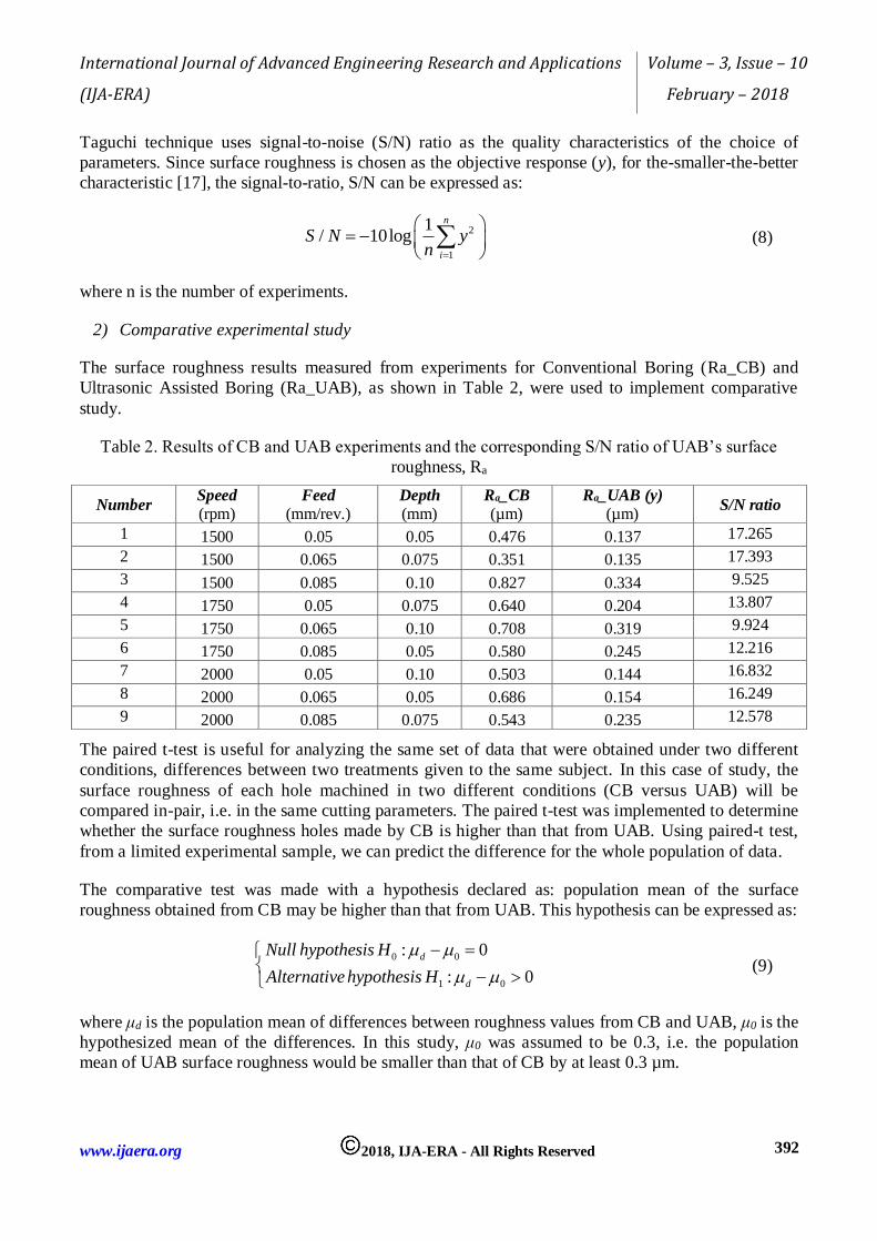
2) Comparative experimental study
The surface roughness results measured from experiments for Conventional Boring (Ra_CB) and
Ultrasonic Assisted Boring (Ra_UAB), as shown in Table 2, were used to implement comparative
study.
Table 2. Results of CB and UAB experiments and the corresponding S/N ratio of UAB’s surface
roughness, Ra
Number Speed
(rpm) Feed
(mm/rev.) Depth
(mm) Ra_CB
(µm) Ra_UAB (y)
(µm) S/N ratio
1 1500 0.05 0.05 0.476 0.137 17.265
2 1500 0.065 0.075 0.351 0.135 17.393
3 1500 0.085 0.10 0.827 0.334 9.525
4 1750 0.05 0.075 0.640 0.204 13.807
5 1750 0.065 0.10 0.708 0.319 9.924
6 1750 0.085 0.05 0.580 0.245 12.216
7 2000 0.05 0.10 0.503 0.144 16.832
8 2000 0.065 0.05 0.686 0.154 16.249
9 2000 0.085 0.075 0.543 0.235 12.578
The paired t-test is useful for analyzing the same set of data that were obtained under two different
conditions, differences between two treatments given to the same subject. In this case of study, the
surface roughness of each hole machined in two different conditions (CB versus UAB) will be
compared in-pair, i.e. in the same cutting parameters. The paired t-test was implemented to determine
whether the surface roughness holes made by CB is higher than that from UAB. Using paired-t test,
from a limited experimental sample, we can predict the difference for the whole population of data.
The comparative test was made with a hypothesis declared as: population mean of the surface
roughness obtained from CB may be higher than that from UAB. This hypothesis can be expressed as:
0 0
1 0
: 0
: 0
d
d
Null hypothesis H
Alternative hypothesis H
(9)
where μd is the population mean of differences between roughness values from CB and UAB, μ0 is the
hypothesized mean of the differences. In this study, μ0 was assumed to be 0.3, i.e. the population
mean of UAB surface roughness would be smaller than that of CB by at least 0.3 µm.

International Journal of Advanced Engineering Research and Applications
(IJA-ERA)
Volume – 3, Issue – 10
February – 2018
www.ijaera.org 2018, IJA-ERA - All Rights Reserved 393
Table 3. Results of Paired T-Test obtained from Minitab
Descriptive Statistics Estimation for Paired Difference
Sample N Mean StDev SE Mean Mean StDev SE Mean 95% Lower Bound
for μ_difference
Ra_CB 9 0.5904 0.1422 0.0474 0.3786 0.0970 0.0323 0.3184
Ra_UAB 9 0.2119 0.0771 0.0257 µ_difference: mean of (Ra_CB - Ra_UAB)
Table 3 presents results obtained from the paired-t test in Minitab software. As can be seen in the
Table, the population mean value of surface roughness, which is obtained from statistical inference,
is of 0.5904 µm for CB, whereas that kind of value is of only 0.2119 µm for UAB. The surface
roughness for CB varied with a standard deviation of 0.1422, whereas that of UAB is only 0.0771. It
can be concluded that, ultrasonic assisted boring provides not only smaller roughness, but also a
narrower band of the roughness range.
Table 4 depicts results of testing the hypothesis declared in Equation (9).
Table 4. The Hypothesis tests
Null hypothesis H₀: μ_difference = 0.3
Alternative hypothesis H₁: μ_difference > 0.3
T-Value 2.43
P-Value 0.021
As can be seen from Table 4, with the p-value of 0.021, i.e. less than 0.05, the alternative hypothesis
(9) can be accepted with a confident of inference of 95%. In conclusion, the mean value of surface
roughness from CB is as higher as at least 0.3 µm, compared to that from UAB. In other word, mean
value of surface roughness is less than around 50% (0.3 µm versus 0.59 µm mean roughness from
CB). The individual value plot shown in Figure 12 also confirms this summary.
Figure 12. Individual plot of surface roughness, Ra, for CB and UAB
3) Taguchi method for choosing cutting parameters
Running the statistical analysis, the results obtained are shown in Table 5 for S/N ratios and in Table 6
for mean values. The Tables show the average of each response characteristic for each level of each

International Journal of Advanced Engineering Research and Applications
(IJA-ERA)
Volume – 3, Issue – 10
February – 2018
www.ijaera.org 2018, IJA-ERA - All Rights Reserved 394
factor. The tables include ranks based on Delta statistics: rank 1 to the highest Delta value, rank 2 to
the second highest, and so on.
As can be seen in Table 5, the ranks indicate that feeding rate (B) has the most influence on the S/N
ratio, and then the speed and depth of cut are the next largest influence, respectively.
Table 5. Response Table for Signal to Noise Ratios
Level A B C
1 14.73 15.97 15.24
2 11.98 14.52 14.59
3 15.22 11.44 12.09
Delta 3.24 4.53 3.15
Rank 2 1 3
Table 6. Response Table for Means
Level A B C
1 0.2020 0.1617 0.1787
2 0.2560 0.2027 0.1913
3 0.1777 0.2713 0.2657
Delta 0.0783 0.1097 0.0870
Rank 3 1 2
Since the goal is to reduce the surface roughness, the factor levels that produce the smallest mean
should be chosen. As can be observed from Table 6, the optimal parameters in the investigated range
for UAB should be:
- Speed (A3): 2000 round per minute;
- Feeding rate (B1): 0.05 mm/revolution;
- Depth of cut (C1): 0.05 mm.
It is worth noting that, in several practical cases, the depth of cut is not determined to obtain a better
surface roughness. Usually the depth of cut is decided by convenient of the machining operator,
depending how the final diameter of the hole must be. In this case, the optimum cutting parameters
should be chosen as Speed (A3=2000) and Feeding rate (0.05).
IV. CONCLUSION
This paper presented an approach to design a vibratory apparatus combined with a jig which can be
clamped on the tool post of conventional lathes. The system includes a commercial ultrasonic
transducer, a horn, a tool holder, which are all fixed on the jig. Theoretical formulas have been
applied to initially determine major dimensions of the ultrasonic horn, which plays the role of
mechanical vibrational amplifier. Because several structures such as a thread hole used to fix the tool
holder, nodal flange for clamping the horn on the jig… can make changes in resonant frequency of
the system, iterate tuning steps have been implemented in the mean of FEA technique. The final
vibratory apparatus has been realized, and then validated by measuring the actual resonant
frequency. The whole rig was used to implement boring experiments. The experimental plan as well
as experimental results have been completed using Taguchi technique, implemented in Minitab

International Journal of Advanced Engineering Research and Applications
(IJA-ERA)
Volume – 3, Issue – 10
February – 2018
www.ijaera.org 2018, IJA-ERA - All Rights Reserved 395
software. It has been shown that, ultrasonic assisted boring can reduce the surface roughness as high
as 50% compared to conventional boring. The vibratory apparatus proposed in this study would
provide a very promising solution to apply ultrasonic assisted machining for making small holes,
especially conical holes, on conventional lathes.
ACKNOWLEDGEMENT
This study has been supported by the project from Ministry of Education and Training, Viet Nam,
under the Grant number B2013-TN02-02.
Conflict of interest: The authors declare that they have no conflict of interest.
Ethical statement: The authors declare that they have followed ethical responsibilities.
REFERENCES
[1] D.E. Brehl, T.A. Dow (2008). Review of vibration-assisted machining, Precision Engineering, vol. 32, pp. 153–172;
[2] Babitsky VI, Mitrofanov AV, Silberschmidt VV (2004). Ultrasonically-assisted turning of aviation materials: simulations and experimental Study. Ultrasonics, vol.42, pp. 81–6.
[3] R. Muhammad, A. Maurotto, A. Roy and V. V. Silberschmid (t2012). Ultrasonically assisted turning of Ti-6Al-2Sn-4Zr-6Mo. Journal of Physics: Conference Series. Vol.382.
[4] Vivekananda, K., G.N. Arka, and S.K. Sahoo (2014). Finite Element Analysis and Process Parameters Optimization of Ultrasonic Vibration Assisted Turning (UVT). Procedia Materials Science, Vol. 6, pp. 1906-1914.
[5] S.A.Sajjady, H.Nouri Hossein Abadi, S.Amini and R.Nosouhi (2016). Analytical and experimental study of topography of surface texture in ultrasonic vibration assisted turning. Materials & Design, Vol.93, pp. 311-323.
[6] He, Y., et al (2016). Ultrasonic elliptical vibration cutting of hard materials: simulation and
experimental study. The International Journal of Advanced Manufacturing Technology, vol. 91(1-4), pp. 363-374.
[7] Sajjady, S.A., et al. (2016), Analytical and experimental study of topography of surface texture in ultrasonic vibration assisted turning. Materials & Design, vol.93, pp. 311-323.
[8] Weber H, Herberger J, Pilz R (1984). Turning of machinable glass ceramics with an ultrasonically vibrated tool. CIRP Ann, vol.33, pp.85–97.
[9] Zhou M, Eow Y, Ngoi B, Lim E (2003). Vibration-assisted precision machining of steel with PCD
tools. Mater Manuf Process, vol.18, pp.825–834. [10] M. N. Kumar, Kanmani Subbu S., Vamsi Krishna P. and Venugopal A. ( 2014 ). Vibration Assisted
Conventional and Advanced Machining: A Review, Procedia Engineering, vol.97, pp. 1577 – 1586. [11] V. Sharma and P.M. Pandey (2016). Recent advances in ultrasonic assisted turning: A step towards
sustainability, Cogent Engineering, vol.3:1222776. [12] G.-L. Chern and Jia-Ming Liang (2007). Study on boring and drilling with vibration cutting,
International Journal of Machine Tools & Manufacture, vol. 47, pp. 133 – 140. [13] T. SOUTOME, S. KARUBE and K. SATO, High Precision Multiple Boring with Combining Ultrasonic
Vibration Cutting and Superposition Superfinishing Process, Transactions Of The Japan Society Of Mechanical Engineers Series C, Vol. 78 (2012) (786), pp. 687-696.
[14] ZVEI - German Electrical Manufacturers Association, Ultrasonic assembly of thermoplastic mouldings and semi-finished products: Recommendations on methods, construction and applications, accessed at www.powerultrasonics.com/content/sonotrodedesign-and-manufacturing-instructions-zveihandbook , in 11/2017.
[15] Allaparthi M., Khan M.R., Addepalli S.N., FE Modal and Harmonic Analysis of Micro Drill with
Ultrasonic Horn. In: Silva L. (eds) Materials Design and Applications. Advanced Structured Materials, vol 65. Springer, Cham, 2017.

International Journal of Advanced Engineering Research and Applications
(IJA-ERA)
Volume – 3, Issue – 10
February – 2018
www.ijaera.org 2018, IJA-ERA - All Rights Reserved 396
[16] Q. Pan, D. Xiao, M. Deng, H. Ren, Y. Xu and C. Xu, A voltage-current method of measuring ultrasonic transducer impedance, IEEE Far East Forum on Nondestructive Evaluation/Testing: New Technology and Application, Jinan, 2013, pp. 125-128; doi: 10.1109/FENDT.2013.6635541.
[17] G. Taguchi, S. Chowdhury and Y. Wu, Taguchi’s Quality Engineering Handbook, John Wiley & Sons, Inc., ISBN: 978-0-471-41334-9, 2004.