33-72 3-phase magnetic starters — enclosed … · ecn2444bah ecn2444cah ecn2444dah 6,655. 6,655....
TRANSCRIPT
33-72
For more information contact Cutler-Hammer at: www.ch.cutler-hammer.com/catalog CAT.201.01.T.E
January 2001
33
3-Phase Magnetic Starters — EnclosedFreedom Line
Vol. 2, Ref. No. [0088]
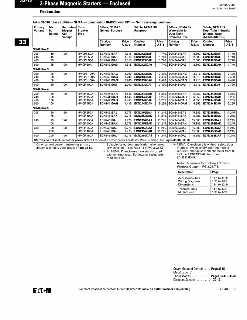
Table 33-116. Class ECN24 — NEMA — Combination HMCP/E with CPT — Non-reversing (Continued)
� Other control power transformer primary and/or secondary voltages, see Page 33-52.
� Suitable for outdoor application when prop-erly installed — see Page i-5 of P.G.3.02.T.E.
� All NEMA 12 enclosures are standardized with external reset. For internal reset, order mod code R5.
� NEMA 12 enclosure is without safety door interlock. When safety door interlock is required, change seventh character from 8 to 9, i.e. ECN2438EAG becomes ECN2439EAG.
Note: Reference to Enclosed Control Product Guide — PG.3.02.T.E.
PrimaryVoltage �
Max.hpRating
Secondary MagnetCoilVoltage
CircuitBreakerType
3-Pole, NEMA 1General Purpose
3-Pole, NEMA 3RRainproof
3-Pole, NEMA 4X Watertight &Dust-TightStainless Steel
3-Pole, NEMA 12Dust-Tight IndustrialExternal Reset(NEMA 3R) ���
CatalogNumber
PriceU.S. $
CatalogNumber
PriceU.S. $
CatalogNumber
PriceU.S. $
CatalogNumber
PriceU.S. $
NEMA Size 2208240480
101525
120 HMCPE 50AHMCPE 50AHMCPE 50A
ECN2421EAFECN2421BAFECN2421CAF
1,515.1,515.1,515.
ECN2422EAFECN2422BAFECN2422CAF
1,740.1,740.1,740.
ECN2424EAFECN2424BAFECN2424CAF
2,500.2,500.2,500.
ECN2428EAFECN2428BAFECN2428CAF
1,740.1,740.1,740.
600 25 120 HMCP 50A ECN2421DA9 1,515. ECN2422DA9 1,740. ECN2424DA9 2,500. ECN2428DA9 1,740.
NEMA Size 3208240480
253050
120 HMCPE 100AHMCPE 100AHMCPE 100A
ECN2431EAGECN2431BAGECN2431CAG
2,200.2,200.2,200.
ECN2432EAGECN2432BAGECN2432CAG
2,490.2,490.2,490.
ECN2434EAGECN2434BAGECN2434CAG
3,915.3,915.3,915.
ECN2438EAGECN2438BAGECN2438CAG
2,490.2,490.2,490.
600 50 120 HMCP 100A ECN2431DAI 2,200. ECN2432DAI 2,490. ECN2434DAI 3,915. ECN2438DAI 2,490.
NEMA Size 4208240480600
4050
100100
120 HMCP 150AHMCP 150AHMCP 150AHMCP 150A
ECN2441EAHECN2441BAHECN2441CAHECN2441DAH
4,445.4,445.4,445.4,445.
ECN2442EAHECN2442BAHECN2442CAHECN2442DAH
5,255.5,255.5,255.5,255.
ECN2444EAHECN2444BAHECN2444CAHECN2444DAH
6,655.6,655.6,655.6,655.
ECN2448EAHECN2448BAHECN2448CAHECN2448DAH
5,255.5,255.5,255.5,255.
NEMA Size 5208 60
75120 HMCP 250A
HMCP 400AECN2451EAJECN2451EAK
9,775.9,775.
ECN2452EAJECN2452EAK
11,245.11,245.
ECN2454EAJECN2454EAK
15,385.15,385.
ECN2458EAJECN2458EAK
11,245.11,245.
240 75100
120 HMCP 250AHMCP 400A
ECN2451BAJECN2451BAK
9,775.9,775.
ECN2452BAJECN2452BAK
11,245.11,245.
ECN2454BAJECN2454BAK
15,385.15,385.
ECN2458BAJECN2458BAK
11,245.11,245.
480 150200
120 HMCP 250AHMCP 400A
ECN2451CAJECN2451CAK
9,775.9,775.
ECN2452CAJECN2452CAK
11,245.11,245.
ECN2454CAJECN2454CAK
15,385.15,385.
ECN2458CAJECN2458CAK
11,245.11,245.
600 200 120 HMCP 250A ECN2451DAJ 9,775. ECN2452DAJ 11,245. ECN2454DAJ 15,385. ECN2458DAJ 11,245.
Starters do not include heater packs. Select 1 carton of 3 heater packs. For Heater Pack Selection, see Pages 33-36 – 33-37.
Description Page
Accessories, KitsWiring DiagramsDimensions
11-1 to 11-111-77 to 1-8512-1 to 12-24
Technical DataMulti-Speed
14-1 to 14-81-37 to 1-39
Cover Mounted Control . . . . . Page 33-50Modifications/Accessories . . . . . . . . . . . . . . Pages 33-41 – 33-49
Discount Symbol . . . . . . . . . . . 1CD-1C
33-40
For more information contact Cutler-Hammer at: www.ch.cutler-hammer.com/catalog CAT.201.01.T.E
January 2001
33
3-Phase Magnetic Starters — EnclosedFreedom Line
Vol. 2, Ref. No. [0056]
ContentsDescription Page
3-Phase Magnetic Starters — Enclosed
Product Description. . . . . . . 33-40
Features . . . . . . . . . . . . . . . . 33-40
Standards and Certifications . . . . . . . . . . . 33-40
Modification Codes . . . . . . . 33-41
Control Power Transformer Kits . . . . . . . . . . . . . . . . . . . 33-49
Cover Control. . . . . . . . . . . . 33-50
Catalog NumberSelection . . . . . . . . . . . . . . 33-52
Product Selection —Non-combinationStarters . . . . . . . . . . . . . . . 33-53
Product Selection —Combination Starterswith Disconnect Switch . . 33-58
Product Selection —Combination Starterswith HMCP. . . . . . . . . . . . . 33-67
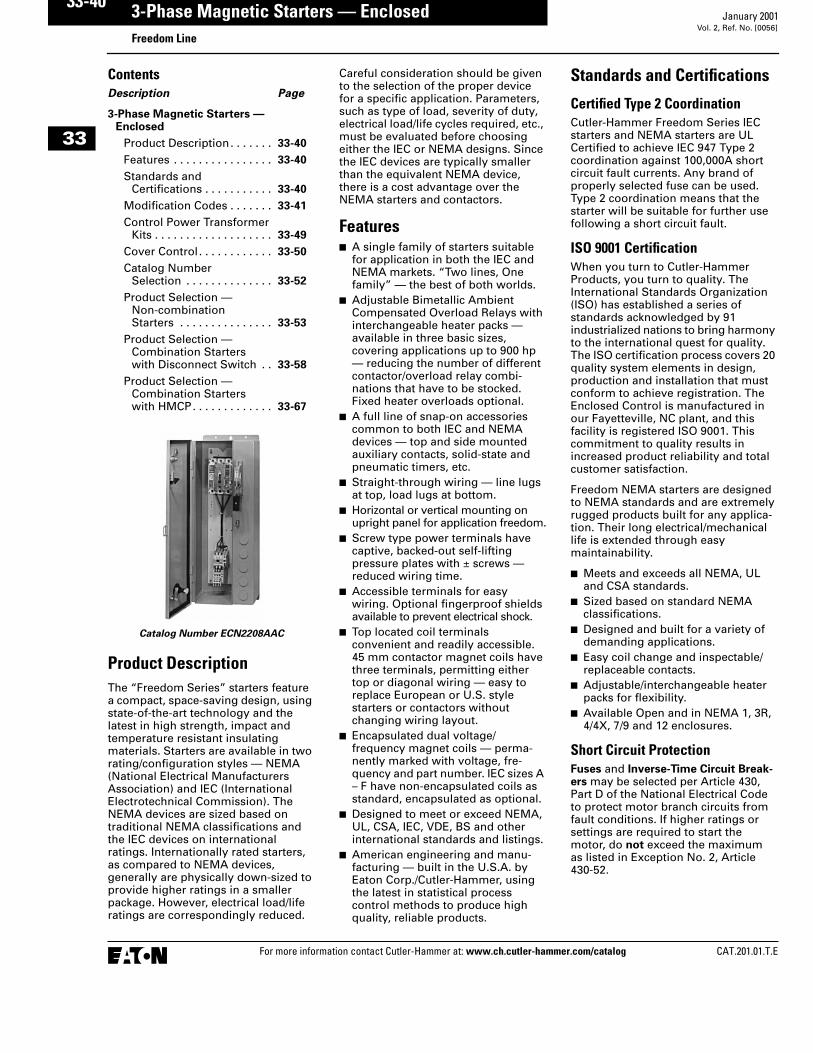
Catalog Number ECN2208AAC
Product Description The “Freedom Series” starters feature a compact, space-saving design, using state-of-the-art technology and the latest in high strength, impact and temperature resistant insulating materials. Starters are available in two rating/configuration styles — NEMA (National Electrical Manufacturers Association) and IEC (International Electrotechnical Commission). The NEMA devices are sized based on traditional NEMA classifications and the IEC devices on international ratings. Internationally rated starters, as compared to NEMA devices, generally are physically down-sized to provide higher ratings in a smaller package. However, electrical load/life ratings are correspondingly reduced.
Careful consideration should be given to the selection of the proper device for a specific application. Parameters, such as type of load, severity of duty, electrical load/life cycles required, etc., must be evaluated before choosing either the IEC or NEMA designs. Since the IEC devices are typically smaller than the equivalent NEMA device, there is a cost advantage over the NEMA starters and contactors.
Features� A single family of starters suitable
for application in both the IEC and NEMA markets. “Two lines, One family” — the best of both worlds.
� Adjustable Bimetallic Ambient Compensated Overload Relays with interchangeable heater packs — available in three basic sizes, covering applications up to 900 hp — reducing the number of different contactor/overload relay combi-nations that have to be stocked. Fixed heater overloads optional.
� A full line of snap-on accessories common to both IEC and NEMA devices — top and side mounted auxiliary contacts, solid-state and pneumatic timers, etc.
� Straight-through wiring — line lugs at top, load lugs at bottom.
� Horizontal or vertical mounting on upright panel for application freedom.
� Screw type power terminals have captive, backed-out self-lifting pressure plates with ± screws — reduced wiring time.
� Accessible terminals for easy wiring. Optional fingerproof shields available to prevent electrical shock.
� Top located coil terminals convenient and readily accessible. 45 mm contactor magnet coils have three terminals, permitting either top or diagonal wiring — easy to replace European or U.S. style starters or contactors without changing wiring layout.
� Encapsulated dual voltage/frequency magnet coils — perma-nently marked with voltage, fre-quency and part number. IEC sizes A – F have non-encapsulated coils as standard, encapsulated as optional.
� Designed to meet or exceed NEMA, UL, CSA, IEC, VDE, BS and other international standards and listings.
� American engineering and manu-facturing — built in the U.S.A. by Eaton Corp./Cutler-Hammer, using the latest in statistical process control methods to produce high quality, reliable products.
Standards and Certifications
Certified Type 2 CoordinationCutler-Hammer Freedom Series IEC starters and NEMA starters are UL Certified to achieve IEC 947 Type 2 coordination against 100,000A short circuit fault currents. Any brand of properly selected fuse can be used. Type 2 coordination means that the starter will be suitable for further use following a short circuit fault.
ISO 9001 CertificationWhen you turn to Cutler-Hammer Products, you turn to quality. The International Standards Organization (ISO) has established a series of standards acknowledged by 91 industrialized nations to bring harmony to the international quest for quality. The ISO certification process covers 20 quality system elements in design, production and installation that must conform to achieve registration. The Enclosed Control is manufactured in our Fayetteville, NC plant, and this facility is registered ISO 9001. This commitment to quality results in increased product reliability and total customer satisfaction.
Freedom NEMA starters are designed to NEMA standards and are extremely rugged products built for any applica-tion. Their long electrical/mechanical life is extended through easy maintainability.
� Meets and exceeds all NEMA, UL and CSA standards.
� Sized based on standard NEMA classifications.
� Designed and built for a variety of demanding applications.
� Easy coil change and inspectable/replaceable contacts.
� Adjustable/interchangeable heater packs for flexibility.
� Available Open and in NEMA 1, 3R, 4/4X, 7/9 and 12 enclosures.
Short Circuit ProtectionFuses and Inverse-Time Circuit Break-ers may be selected per Article 430, Part D of the National Electrical Code to protect motor branch circuits from fault conditions. If higher ratings or settings are required to start the motor, do not exceed the maximum as listed in Exception No. 2, Article 430-52.

33-50
For more information contact Cutler-Hammer at: www.ch.cutler-hammer.com/catalog CAT.201.01.T.E
January 2001
33
3-Phase Magnetic Starters — EnclosedFreedom/Advantage/IT Lines
Vol. 2, Ref. No. [0066]
Cover Control
Non-reversing
Flange Control KitsFor on-the-job conversion of NEMA 1, 3R, 4X and 12 enclosed starters. Knockouts are provided on the NEMA 1 flange. NEMA 3R, 4X and 12 have prepunched holes with removable hole plugs.
Factory Installed Pilot DevicesTo order factory installed pilot devices, change the 9th character of the Catalog Number to the alpha shown in the table below. Example: to order an ECN0514CAA with START/STOP pushbuttons and a red pilot light, change the A to a C, i.e. ECN0514CCA.
Table 33-100. Non-reversing Pilot Devices
� For IEC Combination Cover Control, see Page 34-71.� For ACM Cover Control Option, see Page 33-101.� Add Code Letter from the table below to Catalog Number for voltage — Kits only.
Example: C400T9B.
Note: 120V only for Advantage.� Additional Kits available. See Page 11-19 of P.G.3.02.T.E.
Figure 33-25. Wiring Diagrams
Figure 33-23. Figure 33-24.
Description Non-combinationSizes 00 – 4Sizes A – MNEMA/IEC Freedom SeriesNEMA 1 Enclosure onlyCover Mounted FieldInstallation Kits �
See Figure 33-23
Non-combinationNEMA 1, Sizes 5 – 9NEMA 1, Sizes N – VAll NEMA 3R, 4X, 12All IT Soft Starts
CombinationFreedom NEMA only �
Advantage �
ITCover Mounted FieldInstallation Kits �
See Figure 33-24
Factory Installed Flange Control
Position9 Alpha
NEMA 1 onlySizes 00 – 4Sizes A – M
Non-combo. only �
SeeFigure 33-23
NEMA 1Sizes 5 – 9Sizes N – V
NEMA 3R,4X, 12 �
All Combination
SeeFigure 33-24
CatalogNumber
PriceU.S. $
CatalogNumber
PriceU.S. $
AdderU.S. $
AdderU.S. $
No Cover Mounted Pilot DevicesSTART/STOP Pushbuttonswith Red RUN Pilot Lightwith Red RUN/Green OFF Lights
C400GK0C400GK1C400GK12 �
C400GK16 �
7.55.
155.252.
—C400T1——
—55.——
ABCD
—77.
204.333.
—159.315.472.
ON/OFF Pushbuttonswith Red RUN Pilot Lightwith Red RUN/Green OFF Lights
———
———
C400T2——
55.——
EFG
———
159.315.472.
HAND/OFF/AUTO Selector Switchwith Red RUN Pilot Lightwith Red RUN/Green OFF Lights
C400GK3C400GK32 �
C400GK36 �
55.155.252.
C400T12——
55.——
HJK
77.204.333.
159.315.472.
START PushbuttonON PushbuttonOFF PushbuttonRed RUN Pilot LightGreen OFFRed RUN/Green OFF Pilot Lights
———C400GK42 �
C400GK41 �
C400GK46 �
———
101.101.201.
C400T3C400T4C400T5C400T9 �
C400T10 �
C400T11 �
39.39.39.
101.101.201.
LMNPQR
———
129.129.257.
159.159.159.159.159.315.
START/STOP Selector Switchwith Red RUN Pilot Lightwith Red RUN/Green OFF Lights
———
———
C400T13——
55.——
STU
———
159.315.472.
ON/OFF Selector Switchwith Red RUN Pilot Lightwith Red RUN/Green OFF Lights
———
———
C400T14——
55.——
VWX
———
159.315.472.
Rating Code Letter Rating Code Letter Rating Code Letter
120V 60 Hz208V 60 Hz
AE
240V 60 Hz380V 50 Hz
BL
480V 60 Hz600V 60 Hz
CD
Discount Symbol . . . . . . . . . . . . . . . . . . . . . . 1CD-1C
HandOFF
Auto Black 3/14
Red 1
Hand
Auto
Red 1
Yellow - to CoilA1 Terminal
Black 3/14
Start
Stop
Black 3/14
Red 1
Yellow 2/13
Local Control Options (If Used)Refer to Diagram Inside Enclosure for Connections
Figure ASTART/STOP Pushbutton
S.P.S.T.Switch
Figure B2-Position Selector Switch
S.P.S.T.Switch
Figure C3-Position Selector Switch
S.P.S.T.Switch
Remove Lead fromCoil to Terminal Number 3
Black “A2”
Black “A1”
Figure DPilot Light (Motor RUN)
Black “A1”
Black “A2”
Figure FOverload Tripped
Wire “C”
1
OL
Connect toOL TerminalNo. 96
NC Interlock(If Used)or
Test
Yellow - to CoilA1 Terminal
Reset95
96
97
98
BlackBlack
1
RemoteSwitch
Stop1
L1, X1 or 1
Figure ESTART/STOP
with Pilot Light
Black 3/14
Yellow2/13
Red 1
Start
Stop
Figure GPilot Light (Motor STOP)
33-52
For more information contact Cutler-Hammer at: www.ch.cutler-hammer.com/catalog CAT.201.01.T.E
January 2001
33
3-Phase Magnetic Starters — EnclosedFreedom Line
Vol. 2, Ref. No. [0068]
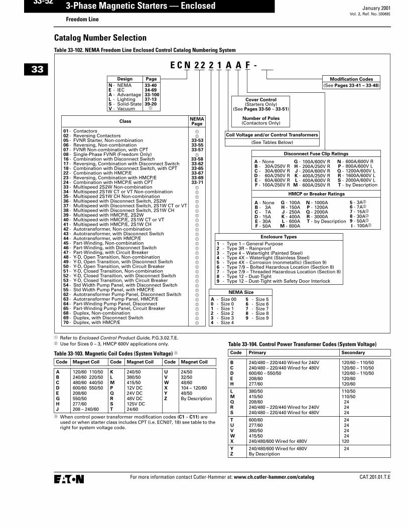
Catalog Number SelectionTable 33-102. NEMA Freedom Line Enclosed Control Catalog Numbering System
� Refer to Enclosed Control Product Guide, P.G.3.02.T.E.� Use for Sizes 0 – 3, HMCP 600V applications only.
Table 33-103. Magnetic Coil Codes (System Voltage) �
� When control power transformer modification codes (C1 – C11) are used or when starter class includes CPT (i.e. ECN07, 18) see table to the right for system voltage code.
Table 33-104. Control Power Transformer Codes (System Voltage)
Modification CodesDesign
ClassNEMAPage
Page
01 - Contactors � 02 - Reversing Contactors �05 - FVNR Starter, Non-combination 33-5306 - Reversing, Non-combination 33-5507 - FVNR Non-combination, with CPT 33-5708 - Single-Phase FVNR (Freedom Only) �16 - Combination with Disconnect Switch 33-5817 - Reversing, Combination with Disconnect Switch 33-6218 - Combination with Disconnect Switch, with CPT 33-6522 - Combination with HMCP/E 33-6723 - Reversing, Combination with HMCP/E 33-6924 - Combination with HMCP/E with CPT 33-7133 - Multispeed 2S2W Non-combination �34 - Multispeed 2S1W CT or VT Non-combination �35 - Multispeed 2S1W CH Non-combination �36 - Multispeed with Disconnect Switch, 2S2W �37 - Multispeed with Disconnect Switch, 2S1W CT or VT �38 - Multispeed with Disconnect Switch, 2S1W CH �39 - Multispeed with HMCP/E, 2S2W �40 - Multispeed with HMCP/E, 2S1W CT or VT �41 - Multispeed with HMCP/E, 2S1W CH �42 - Autotransformer, Non-combination �43 - Autotransformer, with Disconnect Switch �44 - Autotransformer, with HMCP/E �45 - Part-Winding, Non-combination �46 - Part-Winding, with Disconnect Switch �47 - Part-Winding, with Circuit Breaker �48 - Y-D, Open Transition, Non-combination �49 - Y-D, Open Transition, with Disconnect Switch �50 - Y-D, Open Transition, with Circuit Breaker �51 - Y-D, Closed Transition, Non-combination �52 - Y-D, Closed Transition, with Disconnect Switch �53 - Y-D, Closed Transition, with Circuit Breaker �54 - Std Width Pump Panel, with Disconnect Switch �55 - Std Width Pump Panel, with HMCP/E �62 - Autotransformer Pump Panel, Disconnect Switch �63 - Autotransformer Pump Panel, HMCP/E �64 - Part-Winding Pump Panel, Disconnect �65 - Part-Winding Pump Panel, Circuit Breaker �68 - Duplex, Non-combination �69 - Duplex, with Disconnect Switch �70 - Duplex, with HMCP/E �
Enclosure Types
1 - Type 1 – General Purpose2 - Type 3R – Rainproof3 - Type 4 – Watertight (Painted Steel)4 - Type 4X – Watertight (Stainless Steel)5 - Type 4X – Corrosion (nonmetallic) (Section 9)6 - Type 7/9 – Bolted Hazardous Location (Section 8)7 - Type 7/9 – Threaded Hazardous Location (Section 8)8 - Type 12 – Dust-Tight9 - Type 12 – Dust-Tight with Safety Door Interlock
Disconnect Fuse Clip Ratings
None 30A/250V R30A/600V R60A/250V R60A/600V R
100A/250V R
A -B -C -D -E -F -
G -H -J -K -L -
M -
100A/600V R200A/250V R200A/600V R400A/250V R400A/600V R600A/250V R
HMCP or Breaker Ratings
None 3A 7A15A30A50A
A -B -C -D -E -F -
G -H -J -K -L -
M -
100A150A 250A 400A600A800A
N - NEMAE - IECA - AdvantageL - LightingS - Solid-StateV - Vacuum
33-4034-6933-10037-1339-20 �
NEMA Size
A - Size 000 - Size 01 - Size 12 - Size 23 - Size 34 - Size 4
5 - Size 56 - Size 67 - Size 78 - Size 89 - Size 9
Cover Control(Starters Only)
(See Pages 33-50 – 33-51)
Number of Poles(Contactors Only)
(See Pages 33-41 – 33-48)
Coil Voltage and/or Control Transformers
(See Tables Below)
N -P -Q -R -S -T -
600A/600V R800A/600V L1200A/600V L1600A/600V L2000A/600V Lby Description
N -P -Q -R -T -
1000A1200A 2000A 3000Aby Description
5 -6 -7 -8 -9 -I -
3A�
7A� 15A� 30A�
50A�
100A�
E C N 2 2 2 1 A A F -
Code Magnet Coil Code Magnet Coil Code Magnet Coil
ABCDEGHJ
120/60 110/50240/60 220/50480/60 440/50600/60 550/50208/60550/50277/60208 – 240/60
KLMPQRST
240/50380/50415/5012V DC24V DC48V DC125V DC24/60
UVWXYZ
24/5032/5048/60104 – 120/6048/50By Description
Code Primary Secondary
BCDEH
240/480 – 220/440 Wired for 240V240/480 – 220/440 Wired for 480V600/60 – 550/50208/60277/60
120/60 – 110/50120/60 – 110/50120/60 – 110/50120/60120/60
LMQRS
380/50415/50208/60240/480 – 220/440 Wired for 240V240/480 – 220/440 Wired for 480V
110/50110/50242424
TUVWX
600/60277/60380/50415/50240/480/600 Wired for 480V
24242424
120
YZ
240/480/600 Wired for 480VBy Description
24

CAT.201.01.T.E For more information contact Cutler-Hammer at: www.ch.cutler-hammer.com/catalog
33-January 2001 3-Phase Magnetic Starters — Enclosed
Freedom LineVol. 2, Ref. No. [0083]
Product Selection — Combination Starters with HMCP/E� Full Voltage� Interchangeable Heater OLR� 600V Maximum
Table 33-114. Class ECN22 — NEMA — Combination HMCP — Non-reversing
� Starters with 120V coil (for separate control) are available. To order, substitute the letter A for the 8th character of the listed catalog number.
� Suitable for outdoor application when prop-erly installed — see Page i-5 of P.G.3.02.T.E.
� All NEMA 12 enclosures are standardized with external reset. For internal reset, order mod code R5.
� NEMA 12 enclosure is without safety door interlock. When safety door interlock is required, change seventh character from 8 to 9, i.e. ECN2238EAG becomes ECN2239EAG.
Note: Reference to Enclosed Control Product Guide — PG.3.02.T.E.
MotorVoltage
Max.hpRating
MagnetCoilVoltage�
CircuitBreakerType
3-Pole, NEMA 1General Purpose
3-Pole, NEMA 3RRainproof
3-Pole, NEMA 4X Watertight &Dust-TightStainless Steel
3-Pole, NEMA 12Dust-Tight IndustrialExternal Reset(NEMA 3R) ���
CatalogNumber
PriceU.S. $
CatalogNumber
PriceU.S. $
CatalogNumber
PriceU.S. $
CatalogNumber
PriceU.S. $
NEMA Size 0200 1
2208 HMCPE 7A
HMCPE 15AECN2201EACECN2201EAD
850.850.
ECN2202EACECN2202EAD
1,010.1,010.
ECN2204EACECN2204EAD
1,500.1,500.
ECN2208EACECN2208EAD
1,010.1,010.
230 13
240 HMCPE 7AHMCPE 15A
ECN2201BACECN2201BAD
850.850.
ECN2202BACECN2202BAD
1,010.1,010.
ECN2204BACECN2204BAD
1,500.1,500.
ECN2208BACECN2208BAD
1,010.1,010.
460 3/425
480 HMCPE 3AHMCPE 7AHMCPE 15A
ECN2201CABECN2201CACECN2201CAD
850.850.850.
ECN2202CABECN2202CACECN2202CAD
1,010.1,010.1,010.
ECN2204CABECN2204CACECN2204CAD
1,500.1,500.1,500.
ECN2208CABECN2208CACECN2208CAD
1,010.1,010.1,010.
575 135
600 HMCP 3AHMCP 7AHMCP 15A
ECN2201DA5ECN2201DA6ECN2201DA7
850.850.850.
ECN2202DA5ECN2202DA6ECN2202DA7
1,010.1,010.1,010.
ECN2204DA5ECN2204DA6ECN2204DA7
1,500.1,500.1,500.
ECN2208DA5ECN2208DA6ECN2208DA7
1,010.1,010.1,010.
NEMA Size 1200 1
27-1/2
208 HMCPE 7AHMCPE 15AHMCPE 30A
ECN2211EACECN2211EADECN2211EAE
885.885.885.
ECN2212EACECN2212EADECN2212EAE
1,050.1,050.1,050.
ECN2214EACECN2214EADECN2214EAE
1,530.1,530.1,530.
ECN2218EACECN2218EADECN2218EAE
1,050.1,050.1,050.
230 127-1/2
240 HMCPE 7AHMCPE 15AHMCPE 30A
ECN2211BACECN2211BADECN2211BAE
885.885.885.
ECN2212BACECN2212BADECN2212BAE
1,050.1,050.1,050.
ECN2214BACECN2214BADECN2214BAE
1,530.1,530.1,530.
ECN2218BACECN2218BADECN2218BAE
1,050.1,050.1,050.
460 3/425
10
480 HMCPE 3AHMCPE 7AHMCPE 15AHMCPE 30A
ECN2211CABECN2211CACECN2211CADECN2211CAE
885.885.885.885.
ECN2212CABECN2212CACECN2212CADECN2212CAE
1,050.1,050.1,050.1,050.
ECN2214CABECN2214CACECN2214CADECN2214CAE
1,530.1,530.1,530.1,530.
ECN2218CABECN2218CACECN2218CADECN2218CAE
1,050.1,050.1,050.1,050.
575 137-1/2
10
600 HMCP 3AHMCP 7AHMCP 15AHMCP 30A
ECN2211DA5ECN2211DA6ECN2211DA7ECN2211DA8
885.885.885.885.
ECN2212DA5ECN2212DA6ECN2212DA7ECN2212DA8
1,050.1,050.1,050.1,050.
ECN2214DA5ECN2214DA6ECN2214DA7ECN2214DA8
1,530.1,530.1,530.1,530.
ECN2218DA5ECN2218DA6ECN2218DA7ECN2218DA8
1,050.1,050.1,050.1,050.
Starters do not include heater packs. Select 1 carton of 3 heater packs. For Heater Pack Selection, see Pages 33-36 – 33-37.
Description Page
Accessories, KitsWiring DiagramsDimensions
11-1 to 11-111-77 to 1-8512-1 to 12-24
Technical DataMulti-Speed
14-1 to 14-81-37 to 1-39
Cover Mounted Control . . . . . Page 33-50Modifications/Accessories . . . . . . . . . . . . . . Pages 33-41 – 33-49
Discount Symbol . . . . . . . . . . . 1CD-1C

PG.3.02.T.E
14-1February 1999
Coil Data NotesP.U. = Pick-up time is the average
time taken from closing of the coil circuit to main con-tact touch.
D.O. = Drop-out time is the average time taken from opening of the coil circuit to main con-tact separation.
Cold = Coil data with a cold coil.
Hot = Coil data with a hot coil.
All data is based on a standard con-tactor with no auxiliary devices and a 120V AC or 24V DC magnet coil. Coil data has a ±5% range depend-ing on the application, therefore specific data may vary.
Standards and Certifications (Contactors and Starters)� Standard: Designed to meet or
exceed UL, NEMA, IEC, CSA, VDE and BS.
� UL listed: UL File #E1491, Guide #NLDX — Open and NEMA 1, 4, 12 Enclosed
� CSA Certified: CSA File #LR353, Class #321104 Open and NEMA 1 Enclosed
� IEC: IEC 947-4-1, Sizes 6 – 8; IEC 158; IEC 947 Pending
Electrical Life — AC-3 and AC-4 Utilization CategoriesLife Load Curves
Cutler-Hammer’s Freedom Series NEMA contactors have been designed and manufactured for superior life performance in any worldwide application. All testing has been based on requirements as found in NEMA and UL standards and conducted by Cutler-Hammer. Actual application life may vary depending on environmental condi-tions and application duty cycle.
Utilization Categories
AC-1 — Non-inductive or slightly inductive loads, such as resistance furnaces and heating.
AC-2 — Starting of slip-ring motors.
AC-3 — Squirrel cage motors; starting, switching off motors during running.
AC-4 — Squirrel cage motors; start-ing, plugging, inching or jogging.
NOTE: AC-3 tests are conducted at rated device currents and AC-4 tests are conducted at six times rated device currents. All tests have been run at 460V, 60 Hz.
Contactor Choice
� Decide what utilization category your application is and choose the appropriate curve.
� Locate the intersection of the life-load curve of the appropriate contactor with the applications operational current (Ie), as found on the horizontal axis.
� Read the estimated contact life along the vertical axis in number of operational cycles.
Technical DataFreedom NEMA
Table of ContentsDescription Page
Freedom NEMA. . . . . . . . . . . . . 14-1
Freedom Heater
Pack Selection. . . . . . . . . . . . . . 14-4
Advantage . . . . . . . . . . . . . . . . . 14-7
Advantage
Overload Settings. . . . . . . . . . . 14-9
Freedom IEC . . . . . . . . . . . . . . . 14-12
Control Power
Transformer Selection . . . . . . . 14-17
AF91 . . . . . . . . . . . . . . . . . . . . . . 14-19
Vacuum Break . . . . . . . . . . . . . . 14-21
Ampere Rating
of AC Motors . . . . . . . . . . . . . . . 14-22
100,000,000
10,000,000
1,000,000
100,000
Op
erat
ion
s
810 162054 108 162 270 54010,0001000100
Break Amperes
101
100,000,000
10,000,000
1,000,000
100,000
Op
erat
ion
s
189 27 45 90 135 2701000100
Break Amperes
NEMA AC-4 Load Life — Sizes 00 – 5, 480V 60 Hz
NEMA AC-3 Load Life — Sizes 00 – 5, 480V 60 Hz
101
Size00 Size
0
Size1 Size
2 Size3
Size5
Size4
Size00
Size0
Size2
Size3
Size5
Size4
Size1

14-2
PG.3.02.T.E
February 1999
Technical DataFreedom NEMA
Description Contactor Catalog Number/Size
NEMA Size 00 NEMA Size 0 NEMA Size 1 NEMA Size 2 NEMA Size 3
ConfigurationNumber of PolesAuxiliary Contacts, StandardAdd-On Auxiliary Contacts
2, 3, 44th Pole NO (1)Top (4) or Side (4)
2, 3Side NO (1)Top (4) or Side (3)
2, 3, 4, 5Side NO (1)Top (4) or Side (3)
2, 3, 4, 5Side NO (1)Top (4) or Side (3)
2, 3Side NO (1)Left Side (4) or Right Side (3)
Frame Size 45 mm 45 mm 65 mm 65 mm 90 mm
Continuous Ampere Ratings (I) 9A 18A 27A 45A 90A
Maximum Horsepower (hp)1-Phase 115V
230V1/31
12
23
37-1/2
7-1/215
3-Phase 200V230V460V575V
1-1/21-1/222
3355
7-1/27-1/21010
10152525
25305050
AC Magnet Coil DataPick-Up Volts — ColdPick-Up Volts — HotPick-Up VoltamperesPick-Up WattsSealed VoltamperesSealed Watts
74%78%80497.52.4
74%78%10065103.1
74%78%23095287.8
74%78%23095287.8
72%76%39011249.813
Drop-Out Volts — ColdDrop-Out Volts — HotMaximum Operation Rate — Ops/HourPick-Up Time (mS)Drop-Out Time (mS)
45%46%12,0001212
45%46%12,0001212
49%50%12,0002014
49%50%12,0002014
50%52%7,2001411
Coil Operating Range % of Rated Voltage
-15% to +10% -15% to +10% -15% to +10% -15% to +10% -15% to +10%
DC Magnet Coil Data For DC Magnet Coils (and coil data), see Accessories, Page 11-7.
Operating TemperatureMaximum Operating Altitude (ft.)Mechanical Life
-20° to 65°C6,00020,000,000
-20° to 65°C6,00020,000,000
-20° to 65°C6,00010,000,000
-20° to 65°C6,00010,000,000
-20° to 65°C6,0006,000,000
Electrical Life (480V/60 Hz)AC-3AC-4
4,000,00090,000
3,000,00085,000
3,000,00088,000
3,500,00062,000
550,00030,000
Wire RangePower Terminals
Control Terminals
12 – 16 stranded,12 – 14 solid Cu
12 – 16 stranded,12 – 14 solid Cu
8 – 16 stranded,10 – 14 solid Cu
12 – 16 stranded,12 – 14 solid Cu
8 – 14 stranded or solid Cu
12 – 16 stranded,12 – 14 solid Cu
3 – 14 (upper) and/or6 – 14 (lower)stranded or solid Cu12 – 16 stranded,12 – 14 solid Cu
1/0 – 14 Cu
12 – 16 stranded12 – 14 solid Cu
Contact Kit Part Number None None 6-65-2 6-65-8 6-43-2
Auxiliary Contact Rating A600, P300

14-18
PG.3.02.T.E
February 1999
Technical DataControl Power Transformer Selection
Component VA Table
� Intermittent duty coil.
Inrush Sealed
VAR Watts VA VAR Watts VA
Relays
Type AA (1 – 2 Pole)Type D15Type M (2 – 12 Pole)Type M Latch Coil
1864
12236.5
8.5499518.5
2080
15541
87.1
2013
6.62.49
11
117.5
2217
Type MRDType MRD Latch Coil �Type RType RM — Set
— Release
—————
16821.66
——
——
6——
—————
13.221.663.53.1
13.2—
63.53.1
Type TFType TH
34
34
45
34
34
45
Timers
Type D80Type D80 with Inst. Contacts
6089
6795
90130
1820
67
1921
Freedom Series Starters and Contactors
IECSizes A – CSizes D – FSizes G – KSizes L – NSizes P – SSizes T – USize VSizes W – XSize Z
6478
210374
1132————
496595
112216798
1345——
80100230390
1040950
160010002400
7.19.2
274896————
2.43.17.8
13171022——
7.5102849.8
11611252370
NEMASize 00Size 0Sizes 1 – 2Size 3Sizes 4 – 5Sizes 6 – 7Size 8
6478
210374
1132868—
496595
112240
13452060
80100230390
115816002450
7.19.2
27489611—
2.43.17.8
1327.22260
7.5102849.8
1002575
Advantage Contactors and Starters
NEMASize IL, 1 and 2Sizes 3 and 4Sizes 5 and 6
———
———
250500
2600
———
51010
255050

PG.3.02.T.E
1-9February 1999
NEMA Rated Starters — Features■ Designed specifically for use in
applications requiring NEMA rat-ings. Starters meet or exceed NEMA standards ICS 2-1993.
■ Bimetallic Ambient Compensated Overload Relays — available in three basic sizes covering applica-tions up to 900 hp — reducing number of different contactor/overload relay combinations that have to be stocked.
These overload relays feature:
– Selectable Manual or Automatic Reset operation.
– Interchangeable heater packs adjustable ±24% to match motor FLA and calibrated for 1.0 and 1.15 service factors. Heater packs for smaller overload relay will mount in larger overload relay — useful in derating appli-cations such as jogging.
– Load lugs built into relay base.
– Single-phase protection, Class 20 or Class 10 trip time.
– Overload trip indication.
– Electrically isolated NO-NC con-tacts (pull RESET button to test).
■ Long life twin break, silver cad-mium oxide contacts — provide excellent conductivity and supe-rior resistance to welding and arc erosion. Generously sized for low resistance and cool operation.
■ Designed to 3,000,000 electrical operations at maximum hp rat-ings up through 25 hp at 600V.
■ Holding circuit contact(s) sup-plied as standard:
– Sizes 00 – 5 have a NO auxiliary contact block mounted on right-hand side (on Size 00, contact occupies 4th power pole posi-tion — no increase in width).
– Sizes 6 – 7 have a 2NO/NC contact block on top left.
– Size 8 has a NO/NC contact block on top left back and a NO on top right back.
■ Steel mounting plate standard on all open type starters.
■ Wired for separate or common control. (All coil voltages 120V or less are wired for separate control as standard.)
NEMA Freedom Starters
3-Phase Magnetic / Interchangeable Heater OLR / 600V Maximum
NEMA Size 0 Cat. No. AN16BN0AC
NEMA 1 Enclosed StarterCat. No. ECN0511CBA-P25P24NEMA Size 1 Cat. No. AN16DN0AB
Typical Wiring Diagrams — Three-Phase and Single-Phase Applications
Not for Use withAuto Reset OL Relays
Separate Control
Remove Wire “c”when it is supplied.Connect separatecontrol lines to theNo. 1 Terminal onthe remote pilotdevice and Terminal96 on the overloadrelay.
“c”
“A”
When more thanone pushbuttonstation is used,omit Connector
“A” and connectper sketch.
Field Conversionto 1-Phase, Add
Dotted Connections
Remote Pilot Devices
NEMA Size 00
2 WireControl
L1 L2 L3
T1 T2 T3T1 T2 T3
1 A1 A2
A2
2
398979695
1 3
3
32
1
2
L1
T1 T2
T1 T2
L2
1
Start
Start Start
Stop
Stop Stop
3 WireControl
Motor
Motor
Not for Use withAuto Reset OL Relays
Separate Control
Remove Wire “c”when it is supplied.Connect separatecontrol lines to theNo. 1 Terminal onthe remote pilotdevice and Terminal96 on the overloadrelay.
“A”
When more thanone pushbuttonstation is used,omit Connector
“A” and connectper sketch.
Field Conversionto 1-Phase, Add
Dotted Connections
Remote Pilot Devices
NEMA Sizes 0, 1 and 2
2 WireControl
T1 T2 T3
“c”L1 L2 L3
T1 T2 T3
1 A1 A22
3
98979695
1 3
3
32
1
2
L1
T1 T2
T1 T2
L2
1
Start
Start Start
Stop
Stop Stop
3 WireControl
Motor
Motor

i-4
PG.3.02.T.E
February 1999
Enclosure TypesEnclosures provide mechanical and electrical protection for operator and equipment. Brief descriptions of the various types of enclosures offered by Cutler-Hammer are given below. See NEMA Standards Publication No. 250 for more comprehensive descriptions, definitions and/or test criteria.
NEMA Type 1 (Conforms to IP40) —
for Indoor Use
Suitable for most applications where unusual service conditions do not exist and where a measure of pro-tection from accidental contact with enclosed equipment is required. Designed to meet tests for rod entry and rust resistance. Enclosure is sheet steel, treated to resist corro-sion. Depending on the size, knock-outs are provided on the top, bottom and sometimes on the side.
NEMA Type 3R (Conforms to IP52) —
for Outdoor Use
Primarily intended for applications where falling rain, sleet or external ice formations are present. Gasketed cover. Designed to meet tests for rain, rod entry, external icing and rust resistance. Enclosure is sheet steel, treated to resist corrosion. Depending on the size, a blank cover plate is attached to the top (for a conduit hub) and knockouts are pro-vided on the bottom.
Cover-mounted pilot device holes are provided and covered with hole plugs.
NEMA Type 4 (Conforms to IP65) —
for Indoor or Outdoor Use
Provide measure of protection from splashing water, hose-directed water and wind blown dust or rain. Con-structed of sheet steel with gasketed cover.
Designed to meet tests for hose-down, external icing and corrosion protection. Enclosure has two water-tight hubs (power) installed top and bottom of one control hub installed in bottom — depending on size.
Cover-mounted pilot device holes are provided and covered with hole plugs.
NEMA Type 4X (Conforms to IP65) —
for Indoor or Outdoor Use
Provide measure of protection from splashing water, hose-directed water, wind blown dust, rain and corrosion. Constructed of stainless steel with gasketed cover. Designed to meet same tests as Type 4 except enclosure must pass a 200-hour salt spray corrosion resistance test.
NEMA Type 7 — for Hazardous
Gas Locations
For use in Class I, Group C or D indoor locations as defined in the National Electrical Code. NEMA Type 7 enclosures must withstand the pressure generated by explosion of internally trapped gases and be able to contain the explosion so that gases in the surrounding atmo-sphere are not ignited. Under normal operation, the surface tem-perature of the enclosure must be below the point where it could ignite explosive gases present in the sur-rounding atmosphere. Designed to meet explosion, temperature and hydrostatic design tests.
Enclosed ControlGeneral Information
NEMA 1
NEMA 3R
NEMA 4X
NEMA 7 & 9 Bolted