372_20_gb_1007_01
DESCRIPTION
http://www.rmg.com/uploads/myth_download/372_20_gb_1007_01.pdfTRANSCRIPT

Gas pressure regulator RMG 372 372.20
Serving the Gas IndustryWorldwide
OPERATING AND MAINTENANCE INSTRUCTIONS /SPARE PARTS Version 07/2010

Contents Page
1. General information 3
2. Specific maintenance instructions 4
2.1 Pressure-compensating diaphragm 4
2.2 Valve rod 4
2.3 Tightening torques 5
2.4 Lubricants 5
2.5 Screw locking devices
3. Spare parts
3.1.1.1 Spare parts drawings RMG 372 DN 25 and DN 50 - K1a/K2a 6
3.1.1.2 Spare parts drawings RMG 372 DN 25 and DN 50 - K16/K17 7
3.1.2 Spare parts drawings RMG 372 DN 25 and DN 50 8, 9
3.2.1 Spare parts drawings RMG 372 DN 80 through DN 150 10
3.2.2 Spare parts drawings RMG 372 DN 80 through DN 150 11, 12
3.3.1 Spare parts drawing regulating assembly 1 13
3.3.2 Spare parts list regulating assembly 1 14, 15
3.4.1 Spare parts drawing regulating assembly 2 16
3.4.2 Spare parts list regulating assembly 2 17, 18
3.5.1 Spare parts drawing regulating assembly 3 19
3.5.2 Spare parts list regulating assembly 3 20, 21
3.6.1.1 Spare parts drawing actuator K1a 22
3.6.1.2 Spare parts drawing detail Z 23
3.6.1.3 Spare parts drawing SSV flap 23
3.6.1.4 Spare parts drawing actuator K2a 24
3.6.2 Spare parts drawing actuator K1a and K2a 25, 26
3.7.1 Spare parts drawing pressure/force transducer 27
3.7.2 Spare parts list pressure/force transducer 28
4. Parts for maintenance purposes 29, 30, 31
372.20 p.02

372.20 p.03
Note
Caution!Danger of damage to property and/or the environment
Important additional information
Eye catcher Used for:
Danger! Danger to life and limb
1. General information
All persons involved with the assembly, operation and/or maintenance of the RMG 372 gas pressure regulator must read and understand all of the following documents:
- Technical product information 372.00 — this RMG document contains the technical data and dimensions of the equipment as well as instructions concerning construction and mode of operation.
- General operating manual for gas pressure regulators and safety devices�– this RMG document contains information on assembly and operation as well as general information on troubleshooting.
- Operating and maintenance instructions/spare parts 372.20 – this RMG document contains more detailed information on assembly and operation of the gas pressure regulator.
There are national laws and regulations for all sorts of jobs on gas pressure governors, from planning to maintenance. Be sure to comply. (In Germany, for instance, DVGW work sheets G 600, G 459/II, G 491 and G 495.)
Inspection and maintenance intervals depend mostly on operating conditions and the nature and properties of the gas. There are no general rules or recommendations for intervals. For Germany, we recommend to consider maintenance intervals as stated in DVGW work sheet G 495 in a first instance. However, in the mid-term, intervals must be adapted to the requirements of each specific equipment.
During maintenance, components must be cleaned and then checked thoroughly. This is necessary even if there have not been any unusual observations during operation and/or functional testing. Checks must focus, in particular, on diaphragms and seals and all movable parts and their respective bearings. Any and all defective parts must be replaced with new ones. The same applies to O rings removed during disassembly.
Do not use any spare/wear parts and/or oils & lubricants not specifically recommended in the RMG operating and maintenance instructions for spare parts.
In the event spare/wear parts and/or lubricants & oils other than those specifically recommended are used, RMG shall not be liable for any defects and/or consecutive damages attributable to such use of illegal parts, lubricants, oils etc.
Item numbers mentioned in the specific operating and maintenance instructions correspond with the numbers in the spare parts lists and drawings.
Some parts in the lists and drawings are marked with a letter "W". We recommend to always have a reserve of those parts in stock for maintenance purposes. Those spare parts are put together in another separate list at the end of the spare parts list.
1.1 Safety information
In this manual, safety information is highlighted by means of the following titles and eye catchers:
Pressure-compensating diaphragm
DN 25 and DN 50
DN 150 valve seat – Ø 150
Valve rod
Lever
O ring Pressure-compensating diaphragm
O ringO ring Pressure-compensating diaphragm
DN 80 and DN 100
O ringPressure-compensating diaphragm
O ring
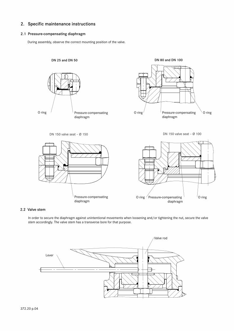
2. Specific maintenance instructions
2.1 Pressure-compensating diaphragm
During assembly, observe the correct mounting position of the valve.
2.2 Valve stem
In order to secure the diaphragm against unintentional movements when loosening and/or tightening the nut, secure the valve stem accordingly. The valve stem has a transverse bore for that purpose.
372.20 p.04
DN 150 valve seat – Ø 100
Tightening torques MA in Nm
Screws & bolts – item no.
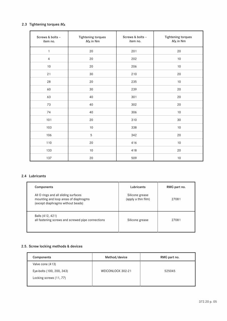
2.3 Tightening torques MA
2.4 Lubricants
Components Lubricants RMG part no.
All O rings and all sliding surfaces Silicone grease mounting and loop areas of diaphragms (apply a thin film) 27081 (except diaphragms without beads)
Balls (412, 421) all fastening screws and screwed pipe connections Silicone grease 27081
Tightening torques MA in Nm
Screws & bolts – item no.
1 20 201 20
4 20 202 10
10 20 206 10
21 30 210 20
28 20 235 10
60 30 239 20
63 40 301 20
73 40 302 20
74 40 306 10
101 20 310 30
103 10 338 10
106 5 342 20
110 20 416 10
133 10 418 20
137 20 509 10
2.5. Screw locking methods & devices
Components Method/device RMG part no.
Valve cone (413)
Eye-bolts (100, 200, 343) WEICONLOCK 302-21 525045
Locking screws (11, 77)
372.20 p. 05
63 4, 5
1
W 2
W 8
9
10
11
12
W 7
13 W
14 W151617
18 W19
20
21
22
1-0,5
23
24
25
29
30 W
31
28
32 W33
26
27 W
X
MA
Z
Y
MA
MA
W
MA
MA
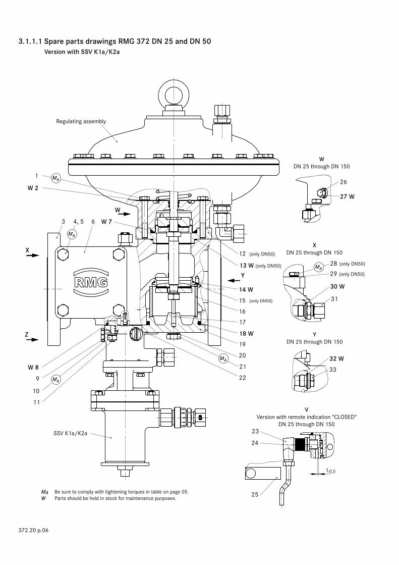
3.1.1.1 Spare parts drawings RMG 372 DN 25 and DN 50 Version with SSV K1a/K2a
MA Be sure to comply with tightening torques in table on page 05.W Parts should be held in stock for maintenance purposes.
372.20 p.06
Regulating assembly
(only DN50)
(only DN50)
(only DN50)
(only DN50)
(only DN50)
WDN 25 through DN 150
XDN 25 through DN 150
VVersion with remote indication "CLOSED"
DN 25 through DN 150
YDN 25 through DN 150
SSV K1a/K2a

22
8 W
9
10
11
MA
3.1.1.2 Spare parts drawings RMG 372 DN 25 and DN 50 Version with SSV K16/K17
MA Be sure to comply with tightening torques in table on page 05.W Parts should be held in stock for maintenance purposes.
372.20 p. 07
(only DN 25 and DN 50)
see 670.20

Item Part no.no. Denomination Number W Materials DN 25 DN 50
372.20 p.08
3.1.2 Spare parts drawings RMG 372 DN 25 and DN 50
W Parts should be held in stock for maintenance purposes
German abbreviations stand for the following materials:St ... steel LM ... light metal/alloy GMs ... cast brassNSt ... stainless steel Ms ... brass GZn ... cast zincFSt ... spring steel GS ... cast steel AlBz ... aluminium bronzeNFSt ... stainless spring steel GGG ... spheroidal graphite cast iron K ... synthetic materialsBz ... bronze GBz ... cast bronze KG ... gummous synthetic materialsCu ... copper GLM ... cast light metal SSt ... foamed materials
1 Hex screw 4 St 10398 10398
2 Sealing ring 4 W LM 18710 18710
3 Body, optional:
3 Body with SSV; PN16 1 GGG 15055018 15056030
3 Body with SSV; PN16 1 GS 15055003 15056014
3 Body with SSV; PN16 1 GS 15055007 15056025
3 Body with SSV; class 150 1 GGG 15055001 15056013
3 Body with SSV; class 150 1 GS 15055004 15056010
3 Body with SSV; class 150 1 GS 15055008 15056027
3 Body without SSV; PN16 1 GGG 15055019 15056019
3 Body without SSV; PN16 1 GS 15055005 15056023
3 Body without SSV; PN16 1 GS 15055009 15056028
3 Body without SSV; class 150 1 GGG 15055002 15056024
3 Body without SSV; class 150 1 GS 15055006 15056051
3 Body without SSV; class 150 1 GS 15055010 15056029
4 Hex screw 8 St 10630 10630
5 Lock washer 8 St 14121 14121
6 SSV cover, optional:
6 SSV cover 2 GGG 15056031 15056031
6 SSV cover 2 GS 15056032 15056032
6 SSV cover 2 GS 15056033 15056033
7 O ring 1 W KG 21261 21261
8 O ring 1 W KG 20832 20832
9 Lock washer 3 St 14122 14122
10 Hex nut 3 St 5559 5559
11 Locking screw 3 St 12473 12473
12 Clamping plate 1 St 15056008
13 O ring 1 W KG 20513
14 O ring 1 W KG 520110 21258
15 Flat head screw 3 St 11145
16 Metal foam ring 1 NSt 15025006 15026027
17 Pin 1 St 15026013 15026013
18 O ring 1 W KG 21271 520001
Item Part no.no. Denomination Number W Materials DN 25 DN 50
372.20 p.09
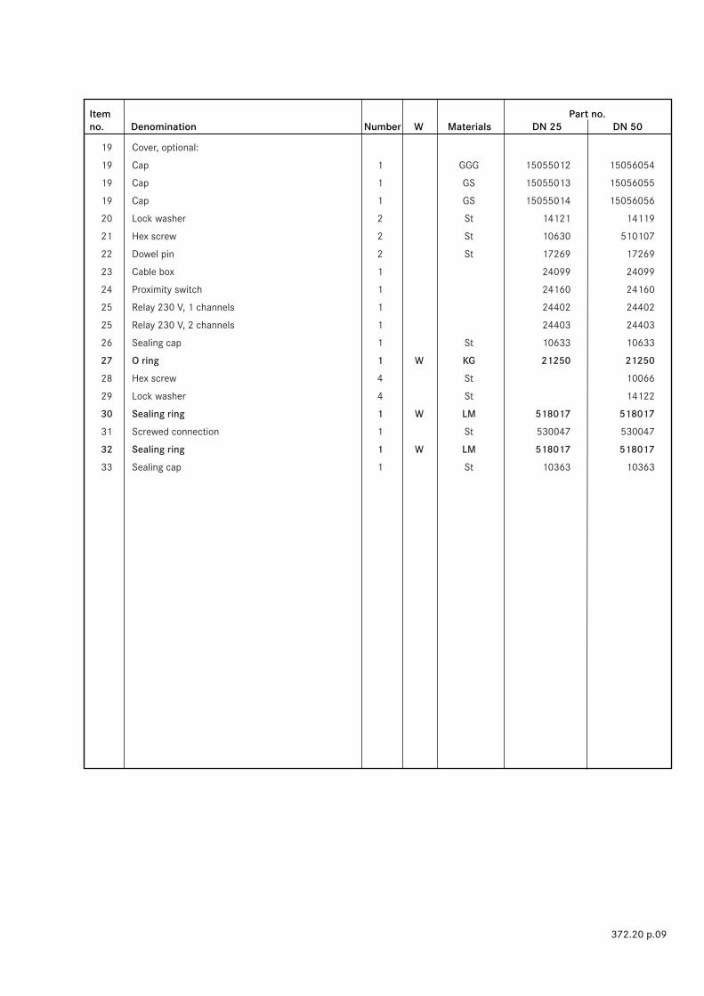
19 Cover, optional:
19 Cap 1 GGG 15055012 15056054
19 Cap 1 GS 15055013 15056055
19 Cap 1 GS 15055014 15056056
20 Lock washer 2 St 14121 14119
21 Hex screw 2 St 10630 510107
22 Dowel pin 2 St 17269 17269
23 Cable box 1 24099 24099
24 Proximity switch 1 24160 24160
25 Relay 230 V, 1 channels 1 24402 24402
25 Relay 230 V, 2 channels 1 24403 24403
26 Sealing cap 1 St 10633 10633
27 O ring 1 W KG 21250 21250
28 Hex screw 4 St 10066
29 Lock washer 4 St 14122
30 Sealing ring 1 W LM 518017 518017
31 Screwed connection 1 St 530047 530047
32 Sealing ring 1 W LM 518017 518017
33 Sealing cap 1 St 10363 10363

60
65
64
63
W 62
61
22
9
10
11
66 W67
68
69
70 W71
72
73
74
75
W 76
77
MA
MA
MA
MA
MA
3.2.1 Spare parts drawings RMG 372 DN 80 thru DN 150
MA Be sure to comply with tightening torques in table on page 05.
W Parts should be held in stock for maintenance purposes.
372.20 p.10
Regulating assembly
Version DN150 with regulating assembly 3
SSV K1a/K2a

Item Part no.no. Denomination Number W Materials DN 80 DN 100 DN 150
370.20 p.11
9 Lock washer 3 St 14122 14122 14122
10 Hex nut 3 St 5559 5559 5559
11 Locking screw 3 St 12473 12473 12473
22 Dowel pin 2 St 17269 17269 17269
23 Cable box 1 24099 24099 24099
24 Proximity switch 1 24160 24160 24160
25 Relay 230 V, 1 channels 1 24402 24402 24402
25 Relay 230 V, 2 channels 1 24403 24403 24403
26 Sealing cap 1 St 10633 10633 10634
27 O ring 1 W KG 21250 21250 21252
30 Sealing ring 1 W LM 518017 518017 518017
31 Screwed connection 1 St 530047 530047 530047
32 Sealing ring 1 W LM 518017 518017 518017
33 Sealing cap 1 St 10363 10363 10363
60 Hex screw 4 St 10630 10630
61 Lock washer 4 St 14121 14121
62 O ring 1 W KG 20428 20428
63 Hex screw 8 St 10630 510001 510113
64 Lock washer 8 St 14121 14119 14116
65 SSV cover, optional:
65 SSV cover 2 GGG 15057016 15058013 15059014
65 SSV cover GS 15057017 15058014 15059015
65 SSV cover GS 15057018 15058015 15059016
66 O ring 1 W KG 21263 21266 520082
67 Body, optional:
67 Body with SSV; PN16 1 GGG 15057101 15058101 15059001
67 Body with SSV; PN16 1 GS 15057103 15058103 15059005
67 Body with SSV; PN16 1 GS 15057105 15058105 15059009
67 Body with SSV; class 150 1 GGG 15057102 15058102 15059002
67 Body with SSV; class 150 1 GS 15057104 15058104 15059006
67 Body with SSV; class 150 1 GS 15057106 15058106 15059010
67 Body without SSV; PN16 1 GGG 15057151 15058151 15059003
67 Body without SSV; PN16 1 GS 15057153 15058153 15059007
67 Body without SSV; PN16 1 GS 15057155 15058155 15059011
67 Body without SSV; class 150 1 GGG 15057152 15058152 15059004
67 Body without SSV; class 150 1 GS 15057154 15058154 15059008
67 Body without SSV; class 150 1 GS 15057156 15058156 15059012
3.2.2 Spare parts drawings RMG 372 DN 80 through DN 150

Item Part no.no. Denomination Number W Materials DN 80 DN 100 DN 150
372.20 p.12
68 Metal foam ring 1 NSt 15027023 15028008 15059035
69 Pin 1 NSt 15057025 15057025 15059044
70 O ring 1 W KG 21272 21267 520107
71 Cover, optional:
71 Cap 1 GGG 15057020 15058017 15059018
71 Cap 1 GS 15057021 15058018 15059019
71 Cap 1 GS 15057022 15058019 15059020
72 Lock washer 3 St 14119 14119 14116
73 Hex screw 3 St 510001 510001 510113
74 Hex nut 4 St 13183
75 Lock washer 4 St 14116
76 O ring 1 W KG 520106
77 Locking screw 4 St 510114
100
W 103 101102104
105
106
107
W 114
109110 108
111
112
113
115
W 117
W 118 119
120
122
W 121
128
129 W
130 W
132
131
133
W 124
W 123
W 125
W 126 137
138
134
135 W
W 116
136 W
127
MA MA
MA
MA
MA
MA
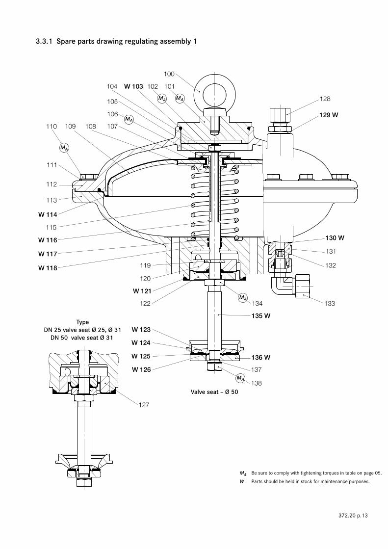
3.3.1 Spare parts drawing regulating assembly 1
MA Be sure to comply with tightening torques in table on page 05.W Parts should be held in stock for maintenance purposes.
372.20 p.13
TypeDN 25 valve seat Ø 25, Ø 31
DN 50 valve seat Ø 31
Valve seat – Ø 50

Item Part no.no. Denomination Number W Materials DN 25 DN 50
372.20 p.14
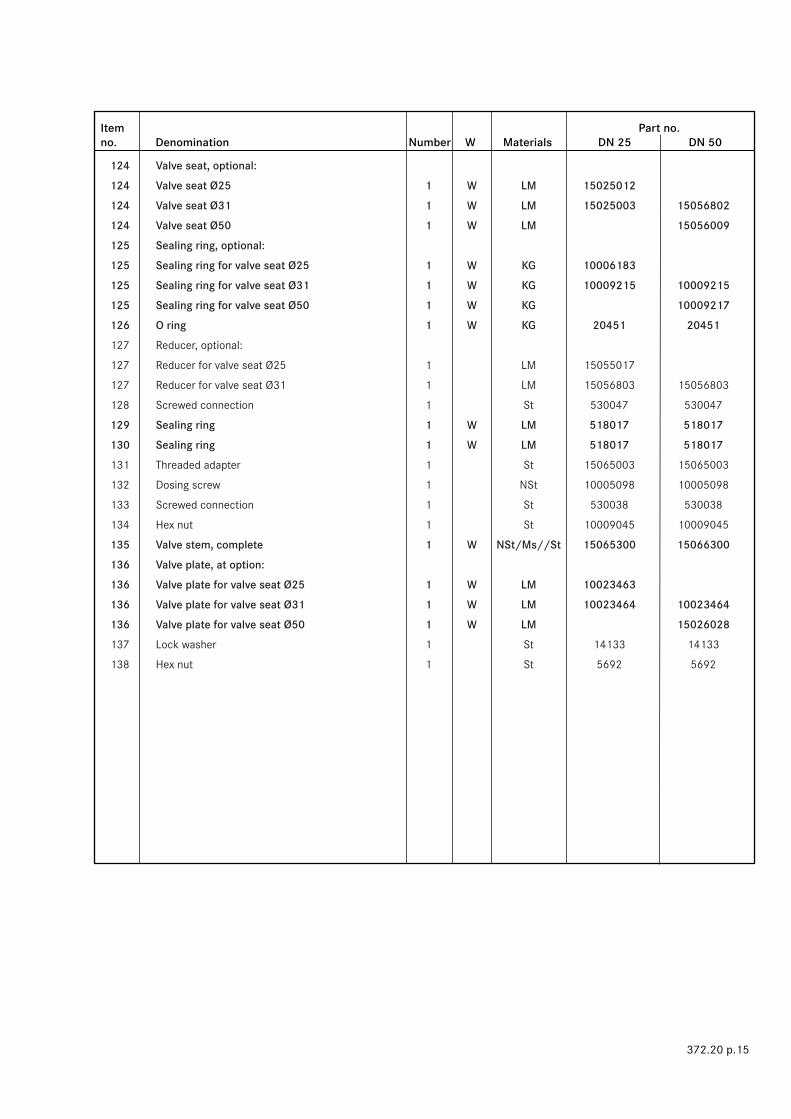
3.3.2 Spare parts list regulating assembly 1
100 Eye bolt 1 St 10487 10487
101 Cover, diaphragm housing 1 LM 15066064 15066064
102 Hex nut 1 St 5559 5559
103 O ring 1 W KG 520104 520104
104 Lock washer 1 St 14122 14122
105 Valve cone 1 LM 10004992 10004992
106 Clamping bolt 1 NSt 15065001 15065001
107 Axial bearing 1 KG 15026024 15026024
108 Spring plate 1 LM 15065002 15065002
109 Diaphragm disc 1 LM 15056006 15056006
110 Hex screw 20 St 510120 510120
111 Washer 20 St 8281 8281
112 Diaphragm housing, UP 1 GLM 15066004 15066004
113 Diaphragm housing, LP 1 GLM 15066003 15066003
114 Diaphragm 1 W KG 15056001 15056001
115 Pressure spring 1 FSt 15056093 15056093
116 Sealing ring 1 W LM 18710 18710
117 O ring 1 W KG 21252 21252
118 Guide belt 1 W KG 15056251 15056251
119 Ring segment, optional:
119 Ring segment for valve seat Ø25 2 Ms 15025018
119 Ring segment for valve seats Ø31, Ø50 2 St 10008612 10008612
120 Diaphragm plate, optional:
120 Diaphragm plate for valve seat Ø25 1 LM 15025015
120 Diaphragm plate for valve seat Ø31 1 LM 15026805 15026805
120 Diaphragm plate for valve seat Ø50 1 LM 15026012
121 Diaphragm, optional:
121 Diaphragm for valve seat Ø25 1 W KG 15025011
121 Diaphragm for valve seat Ø31 1 W KG 15026801 15026801
121 Diaphragm for valve seat Ø50 1 W KG 15026002
122 Pressure disc, optional:
122 Pressure disc for valve seat Ø25 1 LM 15025014
122 Pressure disc for valve seat Ø31 1 LM 15026804 15026804
122 Pressure disc for valve seat Ø50 1 LM 15026011
123 Valve cone, optional:
123 Valve cone for valve seat Ø25 1 W LM 10006184
123 Valve cone for valve seat Ø31 1 W LM 10009199 10009199
123 Valve cone for valve seat Ø50 1 W LM 15056035
Item Part no.no. Denomination Number W Materials DN 25 DN 50
372.20 p.15
124 Valve seat, optional:
124 Valve seat Ø25 1 W LM 15025012
124 Valve seat Ø31 1 W LM 15025003 15056802
124 Valve seat Ø50 1 W LM 15056009
125 Sealing ring, optional:
125 Sealing ring for valve seat Ø25 1 W KG 10006183
125 Sealing ring for valve seat Ø31 1 W KG 10009215 10009215
125 Sealing ring for valve seat Ø50 1 W KG 10009217
126 O ring 1 W KG 20451 20451
127 Reducer, optional:
127 Reducer for valve seat Ø25 1 LM 15055017
127 Reducer for valve seat Ø31 1 LM 15056803 15056803
128 Screwed connection 1 St 530047 530047
129 Sealing ring 1 W LM 518017 518017
130 Sealing ring 1 W LM 518017 518017
131 Threaded adapter 1 St 15065003 15065003
132 Dosing screw 1 NSt 10005098 10005098
133 Screwed connection 1 St 530038 530038
134 Hex nut 1 St 10009045 10009045
135 Valve stem, complete 1 W NSt/Ms//St 15065300 15066300
136 Valve plate, at option:
136 Valve plate for valve seat Ø25 1 W LM 10023463
136 Valve plate for valve seat Ø31 1 W LM 10023464 10023464
136 Valve plate for valve seat Ø50 1 W LM 15026028
137 Lock washer 1 St 14133 14133
138 Hex nut 1 St 5692 5692

W 228
200
W 204 201203
205
206
207
W 214
209210 208
211
212
213
215
W 218
W 219
220
223
W 224
W 221
229
231 W
233
232
234
W 226
W 225
W 227 239
240
236
238 W
230 W
235 W
202
222
237 W
W 216
217
MA
MA MA
MA
MA
MA
3.4.1 Spare parts drawing regulating assembly 2
MA Be sure to comply with tightening torques in table on page 05.W Parts should be held in stock for maintenance purposes.
372.20 p.16
Version with valve seats -Ø 60 and -Ø 80
Valve seat -Ø 100
Item Part no. no. Denomination Number W Materials DN 25 DN 50
372.20 p.17
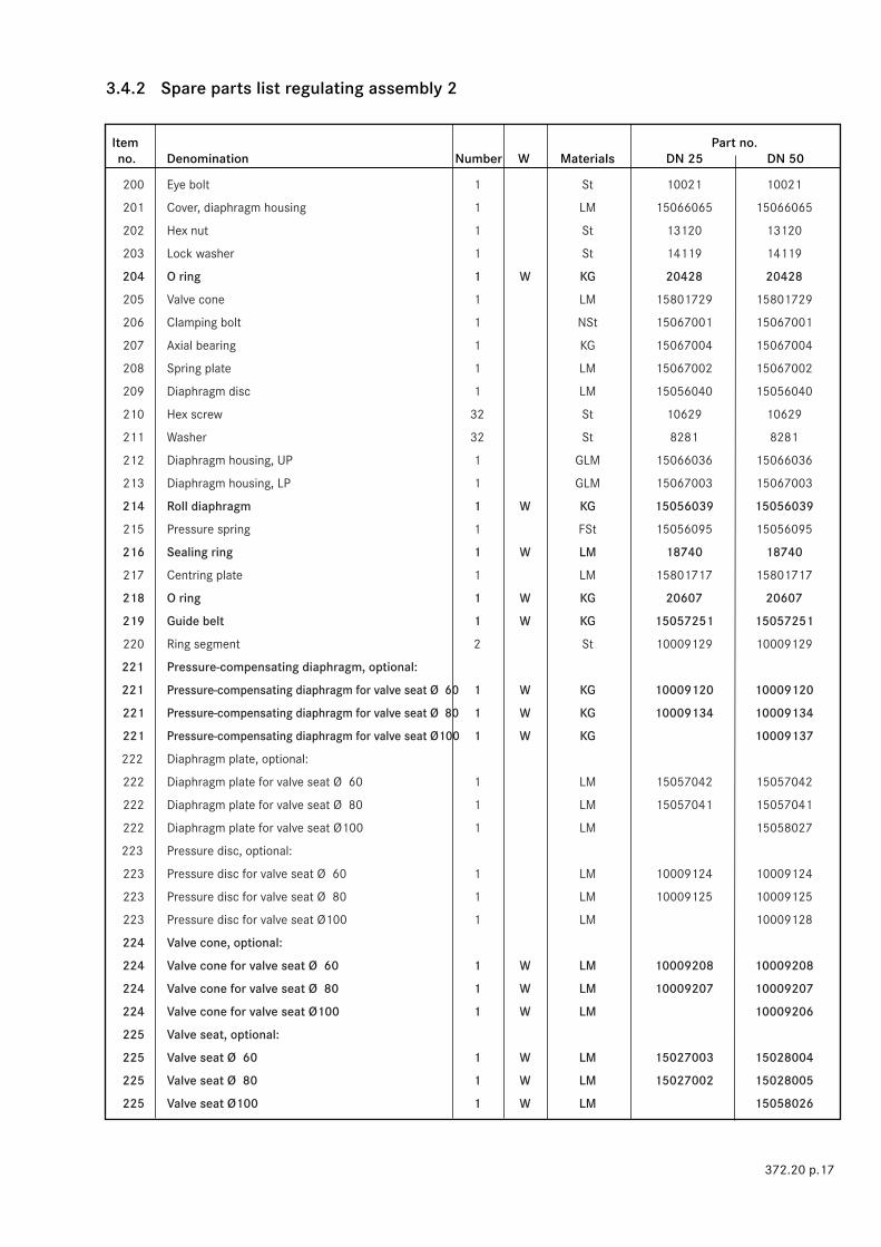
200 Eye bolt 1 St 10021 10021
201 Cover, diaphragm housing 1 LM 15066065 15066065
202 Hex nut 1 St 13120 13120
203 Lock washer 1 St 14119 14119
204 O ring 1 W KG 20428 20428
205 Valve cone 1 LM 15801729 15801729
206 Clamping bolt 1 NSt 15067001 15067001
207 Axial bearing 1 KG 15067004 15067004
208 Spring plate 1 LM 15067002 15067002
209 Diaphragm disc 1 LM 15056040 15056040
210 Hex screw 32 St 10629 10629
211 Washer 32 St 8281 8281
212 Diaphragm housing, UP 1 GLM 15066036 15066036
213 Diaphragm housing, LP 1 GLM 15067003 15067003
214 Roll diaphragm 1 W KG 15056039 15056039
215 Pressure spring 1 FSt 15056095 15056095
216 Sealing ring 1 W LM 18740 18740
217 Centring plate 1 LM 15801717 15801717
218 O ring 1 W KG 20607 20607
219 Guide belt 1 W KG 15057251 15057251
220 Ring segment 2 St 10009129 10009129
221 Pressure-compensating diaphragm, optional:
221 Pressure-compensating diaphragm for valve seat Ø 60 1 W KG 10009120 10009120
221 Pressure-compensating diaphragm for valve seat Ø 80 1 W KG 10009134 10009134
221 Pressure-compensating diaphragm for valve seat Ø100 1 W KG 10009137
222 Diaphragm plate, optional:
222 Diaphragm plate for valve seat Ø 60 1 LM 15057042 15057042
222 Diaphragm plate for valve seat Ø 80 1 LM 15057041 15057041
222 Diaphragm plate for valve seat Ø100 1 LM 15058027
223 Pressure disc, optional:
223 Pressure disc for valve seat Ø 60 1 LM 10009124 10009124
223 Pressure disc for valve seat Ø 80 1 LM 10009125 10009125
223 Pressure disc for valve seat Ø100 1 LM 10009128
224 Valve cone, optional:
224 Valve cone for valve seat Ø 60 1 W LM 10009208 10009208
224 Valve cone for valve seat Ø 80 1 W LM 10009207 10009207
224 Valve cone for valve seat Ø100 1 W LM 10009206
225 Valve seat, optional:
225 Valve seat Ø 60 1 W LM 15027003 15028004
225 Valve seat Ø 80 1 W LM 15027002 15028005
225 Valve seat Ø100 1 W LM 15058026
3.4.2 Spare parts list regulating assembly 2

Item Part no.no. Denomination Number W Materials DN 25 DN 50
372.20 p.18
226 Sealing ring, optional:
226 Sealing ring for valve seat Ø 60 1 W KG 10009218 10009218
226 Sealing ring for valve seat Ø 80 1 W KG 10009219 10009219
226 Sealing ring for valve seat Ø100 1 W KG 10009220
227 O ring 1 W KG 20442 20442
228 Reducer, optional:
228 Reducer for valve seat Ø60 1 LM 15057803 15057803
228 Reducer for valve seat Ø80 1 LM 15057802 15057802
229 Screwed connection 1 St 530047 530047
230 Sealing ring 1 W LM 518017 518017
231 Sealing ring 1 W LM 518017 518017
232 Threaded adapter 1 St 15065003 15065003
233 Dosing screw 1 NSt 10005098 10005098
234 Screwed connection 1 St 530038 530038
235 O ring 1 W KG 20442 20442
236 Hex nut 1 St 10009109 10009109
237 Valve stem, complete 1 W NSt/Ms/St 15067300 15067300
238 Valve plate, at option:
238 Valve plate for valve seat Ø 60 1 W LM 15027020 15027020
238 Valve plate for valve seat Ø 80 1 W LM 15027009 15027009
238 Valve plate for valve seat Ø100 1 W LM 15028009
239 Lock washer 1 St 14116 14116
240 Hex nut 1 St 13203 13203

343 Z
328
327 W
329 W
305
300301302W 303
W 304
306
307
308
330
311
331 332W
333
310
W 314
312
313
309
315
W 316
W 317
W 316
318
319 W 320
321
W 323
W 324
W 325
W 326
334 W
335
336 W
337 W
322
338
339 W
340 W
341
342
Z
MA
MA
MA MA
MA
MA
3.5.1 Spare parts drawing regulating assembly 3
MA Be sure to comply with tightening torques in table on page 05.W Parts should be held in stock for maintenance purposes.
372.20 p.19
Version with valve seat Ø100
Valve seat Ø140

Item Part no.no. Denomination Number W Materials DN 80
372.20 p.20
300 Drain plug 1 KG 26162
301 Cover, diaphragm housing 1 LM 15066065
302 Hex screw 1 St 510115
303 O ring 1 W KG 20428
304 Sealing ring 1 W LM 18710
305 Valve cone 1 LM 10004992
306 Threaded bolt 1 St 15801768
307 Washer 1 NSt 514007
308 Spring plate 1 LM 15801766
309 Diaphragm disc 1 LM 15058022
310 Hex screw 24 St 8182
311 Washer 24 St 8271
312 Diaphragm housing, UP 1 GLM 15068024
313 Diaphragm housing, LP 1 GLM 15069023
314 Roll diaphragm 1 W KG 15058021
315 Spring plate 1 LM 15801766
316 Guide belt 2 W KG 15059251
317 O ring 1 W KG 20619
318 Diaphragm plate, optional:
318 Diaphragm plate for valve seat Ø100 1 LM 15059051
318 Diaphragm plate for valve seat Ø140 1 LM 15059036
319 Ring segment 2 St 15059046
320 Pressure-compensating diaphragm, optional:
320 Pressure-compensating diaphragm for valve seat Ø100 1 W KG 15059057
320 Pressure-compensating diaphragm for valve seat Ø140 1 W KG 15059024
321 Pressure disc, optional:
321 Pressure disc for valve seat Ø100 1 LM 15059052
321 Pressure disc for valve seat Ø140 1 LM 15059037
322 Flat head screw 2 St 510116
323 Valve cone, optional:
323 Valve cone for valve seat Ø100 1 W LM 15059050
323 Valve cone for valve seat Ø140 1 W LM 15801757
324 Valve seat, optional:
324 Valve seat Ø100 1 W LM 15059048
324 Valve seat Ø140 1 W LM 15801759
325 Sealing ring, optional:
325 Sealing ring for valve seat Ø100 1 W KG 15059054
325 Sealing ring for valve seat Ø140 1 W KG 15801762
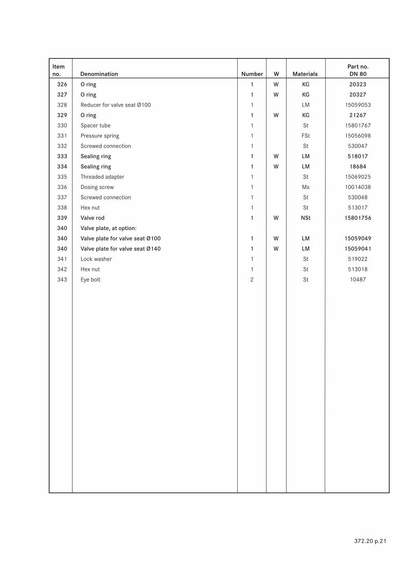
3.5.2 Spare parts list regulating assembly 3
Item Part no.no. Denomination Number W Materials DN 80
372.20 p.21
326 O ring 1 W KG 20323
327 O ring 1 W KG 20327
328 Reducer for valve seat Ø100 1 LM 15059053
329 O ring 1 W KG 21267
330 Spacer tube 1 St 15801767
331 Pressure spring 1 FSt 15056098
332 Screwed connection 1 St 530047
333 Sealing ring 1 W LM 518017
334 Sealing ring 1 W LM 18684
335 Threaded adapter 1 St 15069025
336 Dosing screw 1 Ms 10014038
337 Screwed connection 1 St 530048
338 Hex nut 1 St 513017
339 Valve rod 1 W NSt 15801756
340 Valve plate, at option:
340 Valve plate for valve seat Ø100 1 W LM 15059049
340 Valve plate for valve seat Ø140 1 W LM 15059041
341 Lock washer 1 St 519022
342 Hex nut 1 St 513018
343 Eye bolt 2 St 10487

428453
451452 W
Z
401W 402
W 403
404
405
406
400
W 408
407
W 409
430
429
410
W 411
412
431
434
433
414
415
413
439
437 W
435 W
436
643
416W 417
440
432
419
442 W441
420
418
421
423422 444
445
426
427
446 W
447425
438
424
X
449
450 W
448MA
MA
Y
3.6.1.1 Spare parts drawing actuator K1a (drawings show DN 25 and DN 50)
MA Be sure to comply with tightening torques in table on page 05.W Parts should be held in stock for maintenance purposes.
372.20 p.22
see p. 23
see p. 23
Release at overpressure onlyRelease at
underpressure only
XVersion with RMG 915
Release at overpressure and underpressure

W 454
W 454
455
456
460
461
462
464W
465
466W
467 468463 471W
469470
461
460
462
463
W 464
465
668W 466 667
3.6.1.2 Detail Z Version for DN 80 through DN 150
W Parts should be held in stock for maintenance purposes.
372.20 p.23
Version DN 25
3.6.1.3 View Y SSV flap
Versions DN 50 through DN 150

480
W 482
481
W 483
484
485
486
3.6.1.4 Spare parts drawing actuator K2a
W Parts should be held in stock for maintenance purposes
for items missing, see K1a.
372.20 p.24

Item Part no.no. Denomination Number W Material DN 25 DN 50 DN 80 DN 100 DN 150
372.20 p.25
400 Sealing ring 1 NFSt 19199 19199 19199 19199 519024
401 Retaining bolt 1 NSt 15026019 15026019 15026019 15026019 15059043
402 O ring 1 W KG 21253 21253 21253 21253 20323 403 O ring 1 W KG 21250 21250 21250 21250 20914 404 Bushing 1 Ms 15025016 15027016 15027016 15027016 15059028
405 Torsion spring 1 NSt 15026022 15026022 15027022 15027022 15059032
406 Sleeve 1 NSt 15026023 15026023 15027014 15027014 15059031
407 Axial bearing 1 K 15026024 15026024 15027021 15027021 15059045
408 O ring 1 W KG 21254 21254 520041 520041 20448 409 O ring 1 W KG 21250 21250 21250 21250 20914 410 Spindle bush 1 Ms 15026018 15026018 15027017 15027017 15027017
411 Screwed plug, optional:
411 for version without approach switch 2 KG 26550 26550 26550 26550 26550
411 for version with 1 approach switch 1 KG 26550 26550 26550 26550 26550
412 Sphere 2 NSt 5184 5184 5184 5184 5184
413 Valve cone 1 LM 15026511 15026511 15026511 15026511 15026511
414 Thread insert 4 St 27132 27132 27132 27132 27132
415 Lock washer 4 St 14123 14123 14123 14123 14123
416 Hex screw 4 St 8172 8172 8172 8172 8172
417 O ring 1 W KG 20371 20371 20371 20371 20371 418 Hex nut 4 St 3399 3399 3399 3399 3399
419 Sealing ring 1 FSt 19131 19131 19131 19131 19131
420 Cheese head screw 4 St 10150 10150 10150 10150 10150
421 Sphere 6 NSt 5108 5108 5108 5108 5108
422 Spring retainer 1 K 10008563 10008563 10008563 10008563 10008563
423 Lock bushing, complete 1 LM/St... 10010619 10010619 10010619 10010619 10010619
424 Spring housing 1 GLM 15055020 15055020 15055020 15055020 15055020
425 Valve stem, complete 1 NSt/St 10010614 10010614 10010614 10010614 10010614
426 Spring plate 1 K 10000856 10000856 10000856 10000856 10000856
427 Spring plate 1 Ms 10001844 10001844 10001844 10001844 10001844
428 Pipe 1 LM 10024060 10024060 10024060 10024060 10024060
429 SSV axle 1 NSt/St 15026400 15026400 15027008 15027008 15059029
430 Bushing 1 Ms 15026017 15026017 15027013 15027013 15059027
431 Pressure spring 1 NFSt 15026005 15026005 15027015 15027015 15027015
432 Switch housing, optional:
432 Switch housing for 1 approach switch 1 GLM 15055039 15055039 15057039 15057039 15057039
432 Switch housing for 2 approach switches 1 GLM 15055040 15055040 15057040 15057040 15057040
433 Sealing ring 1 NFSt 19195 19195 19196 19196 19196
434 Lock bushing 1 NSt 15026020 15026020 15027018 15027018 15027018
435 Sealing ring 1 W LM 518017 518017 518017 518017 518017 436 Screwed connection 1 St 530043 530043 530043 530043 530043
437 O ring 1 W KG 21251 21251 21251 21251 21251 438 SSV bottom, complete 1 GLM... 10010605 10010605 10010605 10010605 10010605
439 Pressure spring 1 FSt 10011077 10011077 10011077 10011077 10011077
440 Pressure disc 1 LM 10004882 10004882 10004882 10004882 10004882
3.9.2 Spare parts list actuators K1a and K2a

Item Part no.no. Denomination Number W Material DN 25 DN 50 DN 80 DN 100 DN 150
372.20 p.26
400 Sealing ring 1 NFSt 19199 19199 19199 19199 519024
401 Retaining bolt 1 NSt 15026019 15026019 15026019 15026019 15059043
402 O ring 1 W KG 21253 21253 21253 21253 20323 403 O ring 1 W KG 21250 21250 21250 21250 20914 404 Bushing 1 Ms 15025016 15027016 15027016 15027016 15059028
405 Torsion spring 1 NSt 15026022 15026022 15027022 15027022 15059032
406 Sleeve 1 NSt 15026023 15026023 15027014 15027014 15059031
407 Axial bearing 1 K 15026024 15026024 15027021 15027021 15059045
408 O ring 1 W KG 21254 21254 520041 520041 20448 409 O ring 1 W KG 21250 21250 21250 21250 20914 410 Spindle bush 1 Ms 15026018 15026018 15027017 15027017 15027017
411 Screwed plug, optional:
411 for version without approach switch 2 KG 26550 26550 26550 26550 26550
411 for version with 1 approach switch 1 KG 26550 26550 26550 26550 26550
412 Sphere 2 NSt 5184 5184 5184 5184 5184
413 Valve cone 1 LM 15026511 15026511 15026511 15026511 15026511
414 Thread insert 4 St 27132 27132 27132 27132 27132
415 Lock washer 4 St 14123 14123 14123 14123 14123
416 Hex screw 4 St 8172 8172 8172 8172 8172
417 O ring 1 W KG 20371 20371 20371 20371 20371 418 Hex nut 4 St 3399 3399 3399 3399 3399
419 Sealing ring 1 FSt 19131 19131 19131 19131 19131
420 Cheese head screw 4 St 10150 10150 10150 10150 10150
421 Sphere 6 NSt 5108 5108 5108 5108 5108
422 Spring retainer 1 K 10008563 10008563 10008563 10008563 10008563
423 Lock bushing, complete 1 LM/St... 10010619 10010619 10010619 10010619 10010619
424 Spring housing 1 GLM 15055020 15055020 15055020 15055020 15055020
425 Valve stem, complete 1 NSt/St 10010614 10010614 10010614 10010614 10010614
426 Spring plate 1 K 10000856 10000856 10000856 10000856 10000856
427 Spring plate 1 Ms 10001844 10001844 10001844 10001844 10001844
428 Pipe 1 LM 10024060 10024060 10024060 10024060 10024060
429 SSV axle 1 NSt/St 15026400 15026400 15027008 15027008 15059029
430 Bushing 1 Ms 15026017 15026017 15027013 15027013 15059027
431 Pressure spring 1 NFSt 15026005 15026005 15027015 15027015 15027015
432 Switch housing, optional:
432 Switch housing for 1 approach switch 1 GLM 15055039 15055039 15057039 15057039 15057039
432 Switch housing for 2 approach switches 1 GLM 15055040 15055040 15057040 15057040 15057040
433 Sealing ring 1 NFSt 19195 19195 19196 19196 19196
434 Lock bushing 1 NSt 15026020 15026020 15027018 15027018 15027018
435 Sealing ring 1 W LM 518017 518017 518017 518017 518017 436 Screwed connection 1 St 530043 530043 530043 530043 530043
437 O ring 1 W KG 21251 21251 21251 21251 21251 438 SSV bottom, complete 1 GLM... 10010605 10010605 10010605 10010605 10010605
439 Pressure spring 1 FSt 10011077 10011077 10011077 10011077 10011077
440 Pressure disc 1 LM 10004882 10004882 10004882 10004882 10004882
3.9.2 Spare parts list actuators K1a and K2a

500
501
502
503
504
505
W 506
W 507
508
509
510
511
510
RMG 670
MA
3.7.1 Spare parts drawing – pressure/force transducer
MA Be sure to comply with tightening torques in table on page 05.
W Parts should be held in stock for maintenance purposes.
372.20 p.27
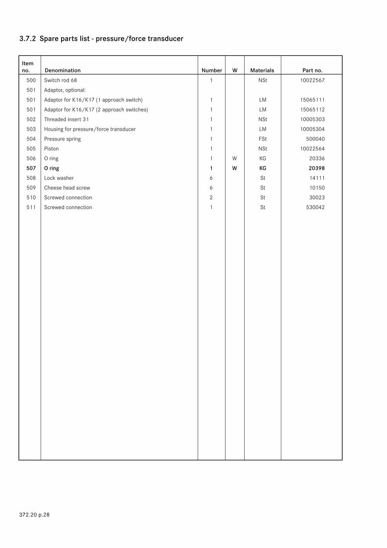
Item no. Denomination Number W Materials Part no.
372.20 p.28
500 Switch rod 68 1 NSt 10022567
501 Adaptor, optional:
501 Adaptor for K16/K17 (1 approach switch) 1 LM 15065111
501 Adaptor for K16/K17 (2 approach switches) 1 LM 15065112
502 Threaded insert 31 1 NSt 10005303
503 Housing for pressure/force transducer 1 LM 10005304
504 Pressure spring 1 FSt 500040
505 Piston 1 NSt 10022564
506 O ring 1 W KG 20336
507 O ring 1 W KG 20398
508 Lock washer 6 St 14111
509 Cheese head screw 6 St 10150
510 Screwed connection 2 St 30023
511 Screwed connection 1 St 530042
3.7.2 Spare parts list - pressure/force transducer
Item Part no.no. Denomination Number DN 25 DN 50 DN 80 DN 100 DN 150
370.20 p.29
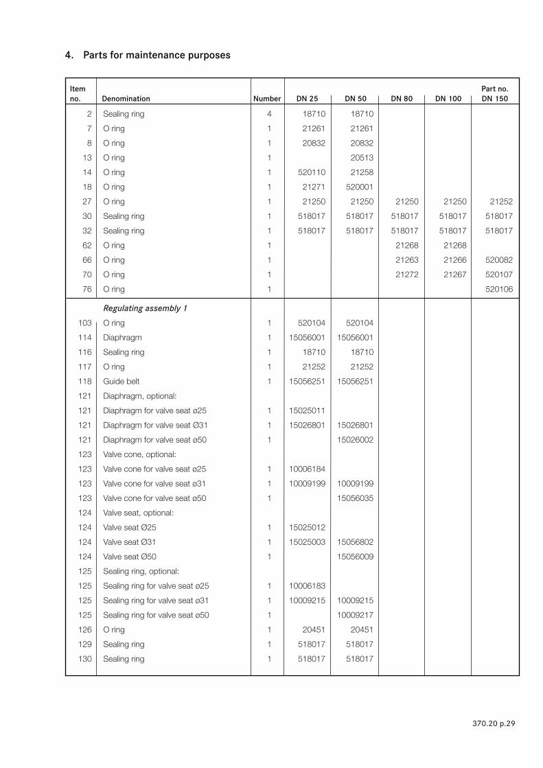
4. Parts for maintenance purposes
2 Sealing ring 4 18710 18710
7 O ring 1 21261 21261
8 O ring 1 20832 20832
13 O ring 1 20513
14 O ring 1 520110 21258
18 O ring 1 21271 520001
27 O ring 1 21250 21250 21250 21250 21252
30 Sealing ring 1 518017 518017 518017 518017 518017
32 Sealing ring 1 518017 518017 518017 518017 518017
62 O ring 1 21268 21268
66 O ring 1 21263 21266 520082
70 O ring 1 21272 21267 520107
76 O ring 1 520106
Regulating assembly 1 103 O ring 1 520104 520104
114 Diaphragm 1 15056001 15056001
116 Sealing ring 1 18710 18710
117 O ring 1 21252 21252
118 Guide belt 1 15056251 15056251
121 Diaphragm, optional:
121 Diaphragm for valve seat ø25 1 15025011
121 Diaphragm for valve seat Ø31 1 15026801 15026801
121 Diaphragm for valve seat ø50 1 15026002
123 Valve cone, optional:
123 Valve cone for valve seat ø25 1 10006184
123 Valve cone for valve seat ø31 1 10009199 10009199
123 Valve cone for valve seat ø50 1 15056035
124 Valve seat, optional:
124 Valve seat Ø25 1 15025012
124 Valve seat Ø31 1 15025003 15056802
124 Valve seat Ø50 1 15056009
125 Sealing ring, optional:
125 Sealing ring for valve seat ø25 1 10006183
125 Sealing ring for valve seat ø31 1 10009215 10009215
125 Sealing ring for valve seat ø50 1 10009217
126 O ring 1 20451 20451
129 Sealing ring 1 518017 518017
130 Sealing ring 1 518017 518017

Item Part no. no. Denomination Number DN 25 DN 50 DN 80 DN 100 DN 150
370.20 p.30
135 Valve stem, complete 1 15065300 15066300
136 Valve plate, at option:
136 Valve plate for valve seat ø25 1 10023463
136 Valve plate for valve seat ø31 1 10023464 10023464
136 Valve plate for valve seat ø50 1 15026028
142 Valve plate, at option:
142 Valve plate for valve seat ø25 1 10023463
142 Valve plate for valve seat ø31 1 10023464 10023464
142 Valve plate for valve seat ø50 1 15026028
Regulating assembly 2 204 O ring 1 20428 20428
214 Roll diaphragm 1 15056039 15056039
216 Sealing ring 1 18740 18740
218 O ring 1 20607 20607
219 Guide belt 1 15057251 15057251
221 Pressure-compensating diaphragm, optional:
221 Pressure-compensating diaphragm for valve seat Ø 60 1 10009120 10009120
221 Pressure-compensating diaphragm for valve seat Ø 80 1 10009134 10009134
221 Pressure-compensating diaphragm for valve seat Ø100 1 10009137
224 Valve cone, optional:
224 Valve cone for valve seat Ø 60 1 10009208 10009208
224 Valve cone for valve seat Ø 80 1 10009207 10009207
224 Valve cone for valve seat Ø100 1 10009206
225 Valve seat, optional:
225 Valve seat ø 60 1 15027003 15028004
225 Valve seat ø 80 1 15027002 15028005
225 Valve seat Ø100 1 15058026
226 Sealing ring, optional:
226 Sealing ring for valve seat Ø 60 1 10009218 10009218
226 Sealing ring for valve seat Ø 80 1 10009219 10009219
226 Sealing ring for valve seat Ø100 1 10009220
227 O ring 1 20442 20442
230 Sealing ring 1 518017 518017
231 Sealing ring 1 518017 518017
235 O ring 1 20442 20442
237 Valve stem, complete 1 15067300 15067300
238 Valve plate, at option:
238 Valve plate for valve seat Ø 60 1 15027020 15027020
238 Valve plate for valve seat Ø 80 1 15027009 15027009

Item Part no.no. Denomination Number DN 25 DN 50 DN 80 DN 100 DN 150
370.20 p.31
Regulating assembly 3 303 O ring 1 20428
304 Sealing ring 1 18710
314 Roll diaphragm 1 15058021
316 Guide belt 1 15059259
317 O ring 1 20619
320 Pressure-compensating diaphragm, optional:
320 Pressure-compensating diaphragm for valve seat Ø100 1 15059057
320 Pressure-compensating diaphragm for valve seat Ø140 1 15059024
323 Valve cone, optional:
323 Valve cone for valve seat Ø100 1 15059050
323 Valve cone for valve seat Ø140 1 15801757
324 Valve seat, optional:
324 Valve seat for valve seat Ø100 1 15059048
324 Valve seat for valve seat Ø140 1 15801459
325 Sealing ring, optional:
325 Sealing ring for valve seat Ø100 1 15059054
325 Sealing ring for valve seat Ø140 1 15801762
326 O ring 1 20323
327 O ring 1 20327
329 O ring 1 21267
333 Sealing ring 1 518017
334 Sealing ring 1 18684
339 Valve rod 1 18801756
340 Valve plate, at option:
340 Valve plate for valve seat Ø100 1 15059049
340 Valve plate for valve seat ø140 1 15059041
For actuators K1a and K2a 402 O ring 1 21253 21253 21253 21253 20323
403 O ring 1 21250 21250 21250 21250 20914
408 O ring 1 21254 21254 520041 520041 20448
409 O ring 1 21250 21250 21250 21250 20914
417 O ring 1 20371 20371 20371 20371 20371
435 Sealing ring 1 518017 518017 518017 518017 518017
437 O ring 1 21251 21251 21251 21251 21251
450 Sealing ring 1 518017 518017 518017 518017 518017
452 Sealing ring 1 518017 518017 518017 518017 518017
454 Sealing ring 2 19199 19199 19199
464 O ring 1 21255 21259 21262 21264 520103
466 Piston, vulcanised 1 15026110 15026110 15026110 15026110 15059033
471 O ring 1 21260 21260 21260 21260
482 O ring 1 21005 21005 21005 21005
485 O ring 1 20361 20361 20361 20361
Pressure/force transducer 506 O ring 1 20336
507 O ring 1 20398
More informationYou want to know more about the solutions RMG can offer to the gas industry? Talk to your local contact. Or visit our websitewww.rmg.com
GERMANYHoneywell Process SolutionsRMG Regel + Messtechnik GmbHOsterholzstrasse 4534123 Kassel, GermanyPhone: +49 (0)561 5007-0Fax: +49 (0)561 5007-107
Honeywell Process SolutionsRMG Messtechnik GmbHOtto-Hahn-Strasse 535510 Butzbach, GermanyPhone: +49 (0)6033 897-0Fax: +49 (0)6033 897-130
Honeywell Process SolutionsRMG Gaselan Regel + Messtechnik GmbHJulius-Pintsch-Ring 315517 Fürstenwalde, GermanyPhone: +49 (0)3361 356-60Fax: +49 (0)3361 356-836
Honeywell Process SolutionsWÄGA Wärme-Gastechnik GmbHOsterholzstrasse 4534123 Kassel, GermanyPhone: +49 (0)561 5007-0Fax: +49 (0)561 5007-207
POLANDHoneywell Process SolutionsGazomet Sp. z o.o.ul. Sarnowska 263-900 Rawicz, PolandPhone: +48 (0)65 5462401Fax: +48 (0)65 5462408
ENGLANDHoneywell Process SolutionsBryan Donkin RMG Gas Controls Ltd.Enterprise Drive, HolmewoodChesterfield S42 5UZ, EnglandPhone: +44 (0)1246 501-501Fax: +44 (0)1246 501-500
CANADAHoneywell Process SolutionsBryan Donkin RMG Canada Ltd.50 Clarke Street South, WoodstockOntario N4S 0A8, CanadaPhone: +1 (0)519 5398531Fax: +1 (0)519 5373339
USAHoneywell Process SolutionsMercury Instruments LLC3940 Virginia AvenueCincinnati, Ohio 45227, USAPhone: +1 (0)513 272-1111Fax: +1 (0)513 272-0211
TURKEYHoneywell Process SolutionsRMG GAZ KONT. SIS. ITH. IHR. LTD. STI.Birlik Sanayi Sitesi, 6. Cd. 62. Sokak No: 7-8-9-10TR - Sasmaz / Ankara, TurkeyPhone: +90 (0)312 27810-80 Fax: +90 (0)312 27828-23
RMG 372.202010-07© 2010 Honeywell International Inc.