3a4409c, e-flo® dc motor, three phase, instructions ... · instructions-installation...
TRANSCRIPT

Instructions-Installation
EEE---Flo®Flo®Flo® DCDCDC Motor,Motor,Motor, ThreeThreeThree PhasePhasePhase 3A4409CEN
ElectricElectricElectric drivedrivedrive forforfor lowlowlow tototo mediummediummedium volumevolumevolume paintpaintpaint circulationcirculationcirculation pumps.pumps.pumps.ForForFor professionalprofessionalprofessional useuseuse only.only.only.
ImportantImportantImportant SafetySafetySafety InstructionsInstructionsInstructionsRead all warnings and instructions in this manual before using theequipment. Save these instructions.
See page 3 for model part numbers andapprovals information.
PROVEN QUALITY. LEADING TECHNOLOGY.

ContentsContentsContentsRelated Manuals.......................................... 2
Models............................................................... 3Basic Models ............................................... 3Basic Models with Region-Specific
Approvals....................................... 4Advanced Models ........................................ 5Advanced Models with Region-Specific
Approvals....................................... 6Warnings ........................................................... 7Installation.......................................................... 11
Check the Oil Level Before Using theEquipment...................................... 11
Power Requirements.................................... 11Connect the Supply Wiring ........................... 12Grounding ................................................... 13Intrinsically Safe Installation Requirements
for Advanced Motors....................... 13Operation........................................................... 14
Startup ........................................................ 14
Shutdown .................................................... 14Pressure Relief Procedure............................ 14Advanced Motor Operation ........................... 14Basic Motor Operation.................................. 15
Maintenance ...................................................... 17Preventive Maintenance Schedule ................ 17Change the Oil............................................. 17Check the Oil Level ...................................... 17
Error Code Troubleshooting ................................ 18Accessories........................................................ 19Appendix A - System Control Drawing
24Z541................................................. 20Mounting Hole Pattern ........................................ 23Technical Specifications...................................... 24Notes ................................................................ 25
RelatedRelatedRelated ManualsManualsManualsManualManualManual No.No.No. DescriptionDescriptionDescription
3A4801 E-Flo DC Repair–Parts
3A2527 E-Flo DC Control Module Kit, Instructions-Parts
2 3A4409C

Models
ModelsModelsModels
BasicBasicBasic ModelsModelsModels
MotorMotorMotor PartPartPart No.No.No. SeriesSeriesSeries HorsepowerHorsepowerHorsepower MaximumMaximumMaximum Force,Force,Force, lbflbflbf (N)(N)(N)
EM1011 A 1 1400 (6227)
EM1021 A 2 3500 (15570)
035903590359 II 2 GEx db IIA T4 Gb 0°C≤Ta≤40°CFM12ATEX0067XIECEx FMG 12.0028X
For Class I, Div. 1, Group D T4.Class 1, Zone 1, AEx db IIA T4Gb 0°C≤Ta≤40°CEx db IIA T4 Gb 0°C≤Ta≤40°CFM17US0033XFM17CA0018X
Figure 1 Basic Motor Identification Label
ListListList ofofof StandardsStandardsStandards
• FM 3600:2018• FM 3615:2018• FM 3810:2018• ANSI/ISA 60079-0:2013• ANSI/UL 60079-1:2015• CSA-C22.2 No. 0.4:2017• CSA-C22.2 No. 0.5:2016• CSA-C22.2 No. 30:R2016
• CAN/CSA-C22.2 No. 60079-0:2015• CAN/CSA-C22.2 No. 60079-1:2016• CAN/CSA-C22.2 No. 61010-1:R2017• EN 60079-0:2012+A11:2013• EN 60079-1:2014• IEC 60079-0 (Ed. 6.0)• IEC 60079-1 (Ed. 7.0)
SpecificSpecificSpecific ConditionsConditionsConditions ofofof Use:Use:Use:
1. Consult the manufacturer if dimensionalinformation on the flameproof joint is necessary.
2. Consult the manufacturer for genuinereplacement fasteners. M8 x 30 socket-headcap screws of Class 12.9 steel or better with aminimum yield strength of 1100 MPa (160,000psi) are acceptable alternatives.
3A4409C 3

Models
BasicBasicBasic ModelsModelsModels withwithwith RegionRegionRegion---SpecificSpecificSpecific ApprovalsApprovalsApprovals
MotorMotorMotor PartPartPart No.No.No. SeriesSeriesSeries HorsepowerHorsepowerHorsepower MaximumMaximumMaximum Force,Force,Force, lbflbflbf (N)(N)(N)
EM1013 A 1 1400 (6227)
EM1023 A 2 3500 (15570)
035903590359 II 2 GEx db IIA T4 Gb 0°C≤Ta≤40°CFM12ATEX0067XIECEx FMG 12.0028X
Figure 2 Basic Motor with Region-Specific ApprovalsIdentification Label
ListListList ofofof StandardsStandardsStandards
• EN 60079-0:2012+A11:2013• EN 60079-1:2014
• IEC 60079-0 (Ed. 6.0)• IEC 60079-1 (Ed. 7.0)
SpecificSpecificSpecific ConditionsConditionsConditions ofofof Use:Use:Use:
1. Consult the manufacturer if dimensionalinformation on the flameproof joint is necessary.
2. Consult the manufacturer for genuinereplacement fasteners. M8 x 30 socket-headcap screws of Class 12.9 steel or better with aminimum yield strength of 1100 MPa (160,000psi) are acceptable alternatives.
4 3A4409C

Models
AdvancedAdvancedAdvanced ModelsModelsModels
MotorMotorMotor PartPartPart No.No.No. SeriesSeriesSeries HorsepowerHorsepowerHorsepower MaximumMaximumMaximum Force,Force,Force, lbflbflbf (N)(N)(N)
EM1012 A 1 1400 (6227)
EM1015 A 1 1400 (6227)
EM1022 A 2 3500 (15570)
EM1025 A 2 3500 (15570)
035903590359 II 2 (1) GEx db [ia op is IIA T4 Ga] IIA T4 Gb0°C≤Ta≤40°CFM12ATEX0067XIECEx FMG 12.0028X
For Class I, Div. 1, Group D T4.Class 1, Zone 1, AEx db [ia op is IIAGa] IIA T4Gb0°C≤Ta≤40°CEx db [ia op is IIA T4 Ga] IIA T4 Gb0°C≤Ta≤40°CFM17US0033XFM17CA0018X
Figure 3 Advanced Motor Identification Label
ListListList ofofof StandardsStandardsStandards
• FM 3600:2018• FM 3610:2018• FM 3615:2018• FM 3810:2018• ANSI/ISA 60079-0:2013• ANSI/ISA 60079-11:2014• ANSI/UL 60079-1:2015• ANSI/UL 60079-28:2017• CSA-C22.2 No. 0.4:2017• CSA-C22.2 No. 0.5:2016• CSA-C22.2 No. 30:R2016• CSA-C22.2 No. 60079-28:2016
• CAN/CSA-C22.2 No. 60079-0:2015• CAN/CSA-C22.2 No. 60079-1:2016• CAN/CSA-C22.2 No. 60079-11:2014• CAN/CSA-C22.2 No. 61010-1:R2017• EN 60079-0:2012+A11:2013• EN 60079-1:2014• EN 60079-11:2012• EN 60079-28:2015• IEC 60079-0 (Ed. 6.0)• IEC 60079-1 (Ed. 7.0)• IEC 60079-11 (Ed. 6.0)• IEC 60079-28 (Ed. 2.0): 2015
SpecificSpecificSpecific ConditionsConditionsConditions ofofof Use:Use:Use:
1. Consult the manufacturer if dimensionalinformation on the flameproof joint is necessary.
2. Consult the manufacturer for genuinereplacement fasteners. M8 x 30 socket-headcap screws of Class 12.9 steel or better with aminimum yield strength of 1100 MPa (160,000psi) are acceptable alternatives.
3A4409C 5

Models
AdvancedAdvancedAdvanced ModelsModelsModels withwithwith RegionRegionRegion---SpecificSpecificSpecific ApprovalsApprovalsApprovals
MotorMotorMotor PartPartPart No.No.No. SeriesSeriesSeries HorsepowerHorsepowerHorsepower MaximumMaximumMaximum Force,Force,Force, lbflbflbf (N)(N)(N)
EM1014 A 1 1400 (6227)
EM1016 A 1 1400 (6227)
EM1024 A 2 3500 (15570)
EM1026 A 2 3500 (15570)
035903590359 II 2 (1) GEx db [ia op is IIA T4 Ga] IIA T4 Gb0°C≤Ta≤40°CFM12ATEX0067XIECEx FMG 12.0028X
Figure 4 Advanced Motor with Region-SpecificApprovals Identification Label
ListListList ofofof StandardsStandardsStandards
• EN 60079-0:2012+A11:2013• EN 60079-1:2014• EN 60079-11:2012• EN 60079-28:2015
• IEC 60079-0 (Ed. 6.0)• IEC 60079-1 (Ed. 7.0)• IEC 60079-11 (Ed. 6.0)• IEC 60079-28 (Ed. 2.0): 2015
SpecificSpecificSpecific ConditionsConditionsConditions ofofof Use:Use:Use:
1. Consult the manufacturer if dimensionalinformation on the flameproof joint is necessary.
2. Consult the manufacturer for genuinereplacement fasteners. M8 x 30 socket-headcap screws of Class 12.9 steel or better with aminimum yield strength of 1100 MPa (160,000psi) are acceptable alternatives.
6 3A4409C

Warnings
WarningsWarningsWarningsThe following warnings are for the setup, use, grounding, maintenance, and repair of this equipment. The exclamationpoint symbol alerts you to a general warning and the hazard symbols refer to procedure-specific risks. When thesesymbols appear in the body of this manual or on warning labels, refer back to these warnings. Product-specific hazardsymbols and warnings not covered in this section may appear throughout the body of this manual where applicable.
DANGERDANGERDANGERSEVERESEVERESEVERE ELECTRICELECTRICELECTRIC SHOCKSHOCKSHOCK HAZARDHAZARDHAZARD
This equipment is powered by more than 240V. Contact with this voltage will cause death or seriousinjury.
• Turn off and disconnect the power at the main switch before disconnecting any cables and beforeservicing equipment.
• This equipment must be grounded. Connect only to a grounded power source.• All electrical wiring must be done by a qualified electrician and comply with all local codes andregulations.
WARNINGWARNINGWARNINGFIREFIREFIRE ANDANDAND EXPLOSIONEXPLOSIONEXPLOSION HAZARDHAZARDHAZARD
Flammable fumes, such as solvent and paint fumes, in work area can ignite or explode. Paint orsolvent flowing through the equipment can cause static sparking. To help prevent fire and explosion:
• Use equipment only in well-ventilated area.• Eliminate all ignition sources; such as pilot lights, cigarettes, portable electric lamps, and plasticdrop cloths (potential static sparking).
• Ground all equipment in the work area. See GroundingGroundingGrounding instructions.• Keep work area free of debris, including solvent, rags, and gasoline.• Do not plug or unplug power cords, or turn power or light switches on or off when flammablefumes are present.
• Use only grounded hoses.• Hold gun firmly to side of grounded pail when triggering into pail. Do not use pail liners unless theyare antistatic or conductive.
• StopStopStop operationoperationoperation immediatelyimmediatelyimmediately if static sparking occurs or you feel a shock. Do not use equipment untilyou identify and correct the problem.
• Keep a working fire extinguisher in the work area.
SPECIALSPECIALSPECIAL CONDITIONSCONDITIONSCONDITIONS FORFORFOR SAFESAFESAFE USEUSEUSE
• To prevent the risk of electrostatic sparking, the equipment’s non-metallic parts should be cleanedonly with a damp cloth.
• The aluminum housing may spark upon impact or contact with moving parts, which may cause fireor explosion. Take precautions to avoid such impact or contact.
• All flameproof joints are critical to the integrity of the motor as approved for hazardous locationsand are not repairable if damaged. Damaged parts must be replaced only with genuine Gracoparts with no substitutions.
3A4409C 7

Warnings
WARNINGWARNINGWARNINGINTRINSICINTRINSICINTRINSIC SAFETYSAFETYSAFETY
Intrinsically safe equipment that is installed improperly or connected to non-intrinsically safeequipment will create a hazardous condition and can cause fire, explosion, or electric shock. Followlocal regulations and the following safety requirements.
• Be sure your installation complies with national, state, and local codes for the installation ofelectrical apparatus in a Class I, Group D, Division 1 Hazardous Location, including all of the localsafety fire codes, NFPA 33, NEC 500 and 516, and OSHA 1910.107.
• Equipment that comes in contact with the equipment’s intrinsically safe terminals mustmeet the entity parameter requirements specified in Control Drawing 24Z541. SeeIntrinsically Safe Installation Requirements for Advanced Motors, page 13. This includes safetybarriers, DC voltage meters, ohmmeters, cables, and connections. Remove the unit from thehazardous area when troubleshooting.
• Do not install any equipment approved only for a non-hazardous location in a hazardous area, asdefined in Article 500 of the National Electrical Code (USA) or your local electrical code. See the IDlabel for the intrinsic safety rating for your equipment.
• Ground the motor. Use a 12 gauge minimum ground wire, connected to a true earth ground.See Grounding, page 13.
• Do not operate the motor with any cover removed.• Do not substitute system components, as this may impair intrinsic safety.
BURNBURNBURN HAZARDHAZARDHAZARD
Equipment surfaces and fluid that is heated can become very hot during operation. To avoid severeburns:
• Do not touch hot fluid or equipment.
MOVINGMOVINGMOVING PARTSPARTSPARTS HAZARDHAZARDHAZARD
Moving parts can pinch, cut, or amputate fingers and other body parts.
• Keep clear of moving parts.• Do not operate equipment with protective guards or covers removed.• Pressurized equipment can start without warning. Before checking, moving, or servicing equipment,follow the PressurePressurePressure ReliefReliefRelief ProcedureProcedureProcedure and disconnect all power sources.
8 3A4409C

Warnings
WARNINGWARNINGWARNINGSKINSKINSKIN INJECTIONINJECTIONINJECTION HAZARDHAZARDHAZARD
High-pressure fluid from dispensing device, hose leaks, or ruptured components will pierce skin.This may look like just a cut, but it is a serious injury that can result in amputation. GetGetGet immediateimmediateimmediatesurgicalsurgicalsurgical treatment.treatment.treatment.
• Engage trigger lock when not dispensing.• Do not point dispensing device at anyone or at any part of the body.• Do not put your hand over the fluid outlet.• Do not stop or deflect leaks with your hand, body, glove, or rag.• Follow the PressurePressurePressure ReliefReliefRelief ProcedureProcedureProcedure when you stop dispensing and before cleaning, checking, orservicing equipment.
• Tighten all fluid connections before operating the equipment.• Check hoses and couplings daily. Replace worn or damaged parts immediately.
EQUIPMENTEQUIPMENTEQUIPMENT MISUSEMISUSEMISUSE HAZARDHAZARDHAZARD
Misuse can cause death or serious injury.
• Do not operate the unit when fatigued or under the influence of drugs or alcohol.• Do not exceed the maximum working pressure or temperature rating of the lowest rated systemcomponent. See TechnicalTechnicalTechnical SpecificationsSpecificationsSpecifications in all equipment manuals.
• Use fluids and solvents that are compatible with equipment wetted parts. See TechnicalTechnicalTechnicalSpecificationsSpecificationsSpecifications in all equipment manuals. Read fluid and solvent manufacturer’s warnings. Forcomplete information about your material, request Safety Data Sheets (SDSs) from distributoror retailer.
• Do not leave the work area while equipment is energized or under pressure.• Turn off all equipment and follow the PressurePressurePressure ReliefReliefRelief ProcedureProcedureProcedure when equipment is not in use.• Check equipment daily. Repair or replace worn or damaged parts immediately with genuinemanufacturer’s replacement parts only.
• Do not alter or modify equipment. Alterations or modifications may void agency approvals andcreate safety hazards.
• Make sure all equipment is rated and approved for the environment in which you are using it.• Use equipment only for its intended purpose. Call your distributor for information.• Route hoses and cables away from traffic areas, sharp edges, moving parts, and hot surfaces.• Do not kink or over bend hoses or use hoses to pull equipment.• Keep children and animals away from work area.• Comply with all applicable safety regulations.
3A4409C 9

Warnings
WARNINGWARNINGWARNINGTOXICTOXICTOXIC FLUIDFLUIDFLUID OROROR FUMESFUMESFUMES HAZARDHAZARDHAZARD
Toxic fluids or fumes can cause serious injury or death if splashed in the eyes or on skin, inhaled, orswallowed.
• Read Safety Data Sheets (SDSs) to know the specific hazards of the fluids you are using.• Store hazardous fluid in approved containers, and dispose of it according to applicable guidelines.
PERSONALPERSONALPERSONAL PROTECTIVEPROTECTIVEPROTECTIVE EQUIPMENTEQUIPMENTEQUIPMENT
Wear appropriate protective equipment when in the work area to help prevent serious injury, includingeye injury, hearing loss, inhalation of toxic fumes, and burns. Protective equipment includes butis not limited to:
• Protective eyewear, and hearing protection.• Respirators, protective clothing, and gloves as recommended by the fluid and solvent manufacturer.
10 3A4409C

Installation
InstallationInstallationInstallation
Improper wiring may cause electric shock or otherserious injury if work is not performed properly.
• This equipment must be grounded. Connectonly to a grounded power source.
• All electrical wiring must be done by a qualifiedelectrician and comply with all local codes andregulations.
NOTE:NOTE:NOTE: To install an advanced motor, also seeIntrinsically Safe Installation Requirements forAdvanced Motors, page 13.
CheckCheckCheck thethethe OilOilOil LevelLevelLevel BeforeBeforeBefore UsingUsingUsing thethetheEquipmentEquipmentEquipment
The motor is pre-filled with oil. Before using theequipment, replace the shipping plug with the ventedfill cap (P) that is included with the motor.
Figure 5 Sightglass and Oil Fill Cap
PowerPowerPower RequirementsRequirementsRequirements
See Table 1 for power requirements. The systemrequires a dedicated circuit protected with a circuitbreaker.
TableTableTable 111 ... PowerPowerPower SpecificationsSpecificationsSpecifications
Model*Model*Model* VoltageVoltageVoltage PhasePhasePhase HzHzHz kVAkVAkVA
EM101x 380–480Vac
3 50/60 1.5
EM102x 380–480Vac
3 50/60 3.0
* The last digit of the Model No. varies. See theModelsModelsModels tables on pages 3–6.
HazardousHazardousHazardous LocationLocationLocation CablingCablingCabling andandand ConduitConduitConduitRequirementsRequirementsRequirements
ExplosionExplosionExplosion ProofProofProof
All electrical wiring in the hazardous location mustbe encased in Class I, Division I, Group D approvedexplosion-proof conduit. Follow all National, State,and Local electric codes.
A conduit seal (D) is required within 18 in. (457 mm)of the motor for the US and Canada.
All cables must be rated at 70°C.
FlameFlameFlame ProofProofProof (ATEX)(ATEX)(ATEX)
Use appropriate conduit, connectors, and cableglands rated for ATEX II 2 G. Follow all local electriccodes.
All cable glands and cables must be rated at 70°C.
3A4409C 11

Installation
ConnectConnectConnect thethethe SupplySupplySupply WiringWiringWiring
1. Ensure that the disconnect (B) is shut off andlocked out.
Figure 6 Example of a Locked Out Disconnect2. Install a start/stop control (C) in the electrical
supply line (A), within easy reach of theequipment. The start/stop control must beapproved for use in hazardous locations.
3. Open the electrical compartment (S) on themotor.
4. Bring the supply wires into the electricalcompartment through the 3/4–14 npt(f) inlet port.Connect the wires to the terminals, as shown.Torque the terminal nuts to 15 in-lb (2 N•m)maximum. DoDoDo notnotnot over-torque.over-torque.over-torque.
5. Close the electrical compartment. Torque thecover screws (J) to 15 ft-lb (20 N•m).
Figure 7 Connect the Supply Wires
NotesNotesNotes forforfor Fig.Fig.Fig. 777
1Tighten all terminal nuts to 15 in-lb (2 N•m)maximum. DoDoDo notnotnot overoverover---torque.torque.torque.
2Tighten cover screws to 15 ft-lb (20 N•m).
3A conduit seal (D) is required within 18in. (457 mm) of the motor for the US andCanada.
12 3A4409C

Installation
GroundingGroundingGrounding
This equipment must be grounded to reduce therisk of static sparking and electric shock. Electricor static sparking can cause fumes to ignite orexplode. Improper grounding can cause electricshock. Grounding provides an escape wire for theelectric current.
1. Connect the supply ground wire in the electricalcompartment as shown in Fig. 7.
2. Connect a ground wire as shown in Fig. 8.Loosen the ground screw and attach a groundwire (Y, Graco part 222011, not supplied).Tighten the ground screw securely. Connectthe other end of the ground wire to a true earthground.
Figure 8 Ground Wire
IntrinsicallyIntrinsicallyIntrinsically SafeSafeSafe InstallationInstallationInstallationRequirementsRequirementsRequirements forforfor AdvancedAdvancedAdvanced MotorsMotorsMotors
Do not substitute or modify system componentsas this may impair intrinsic safety. For componentinstallation, maintenance, or operation instructions,read the component system manuals. Only installequipment in a hazardous location if the equipmentis approved for a hazardous location. See theidentification label for the intrinsic safety rating foryour model.
See Appendix A - System Control Drawing 24Z541,page 20, for installation requirements and entityparameters. Follow all installation instructions in yoursystem component manuals.
3A4409C 13

Operation
OperationOperationOperation
StartupStartupStartup
1. Unlock the fused safety switch (B) and turn it on.See Connect the Supply Wiring, page 12.
2. Press the start pushbutton (C).3. Check that the power indicator (L) is lit (steady
on).4. See Advanced Motor Operation, page 14 or
Basic Motor Operation, page 15 for furtherinstructions.
Figure 9 Power Indicator
ShutdownShutdownShutdown
Follow the Pressure Relief Procedure, page 14.
PressurePressurePressure ReliefReliefRelief ProcedureProcedureProcedure
Follow the Pressure Relief Procedurewhenever you see this symbol.
This equipment stays pressurized until pressureis manually relieved. To help prevent seriousinjury from pressurized fluid, such as skin injection,splashing fluid and moving parts, follow thePressure Relief Procedure when you stop sprayingand before cleaning, checking, or servicing theequipment.
1. Disengage the start/stop control (C). SeeConnect the Supply Wiring, page 12.
2. Shut off and lock out the fused safety switch (B).3. Relieve all fluid pressure as explained in your
separate pump manual.
AdvancedAdvancedAdvanced MotorMotorMotor OperationOperationOperation
The Advanced E-Flo DC motors require installation ofthe 17V232 or 17V233 Control Module Accessory Kitto provide the interface for users to enter selectionsand view information related to setup and operation.See the Control Module Accessory Kit manual3A2527 for installation and operation information.
NOTICENOTICENOTICETo prevent damage to the softkey buttons, do notpress the buttons with sharp objects such as pens,plastic cards, or fingernails.
Figure 10 Control Module Accessory
14 3A4409C

Operation
BasicBasicBasic MotorMotorMotor OperationOperationOperation
The basic motor has three operating modes:
• Pressure Mode• Pressure Mode with Integrated Runaway
Protection
• Flow Mode
NOTE:NOTE:NOTE: Before changing from one mode to another,turn the Control Knob (N) fully counterclockwise to 0.
PressurePressurePressure ModeModeMode
When in pressure mode, the motor will adjust thespeed to maintain a constant fluid pressure.
1. Turn the Control Knob (N) fully counterclockwiseto 0.
2. Pull the Mode Select switch (M) out to set. Turn
the switch to Pressure . Push the switch into lock.
3. Pull the Control Knob (N) out to set. Turn theknob clockwise to increase the pressure, orcounterclockwise to decrease the pressure.Push the knob in to lock.
Figure 11 Pressure Mode
PressurePressurePressure ModeModeMode withwithwith IntegratedIntegratedIntegrated RunawayRunawayRunawayProtectionProtectionProtection
In pressure mode with integrated runaway protection,the motor will adjust the speed to maintain a constantfluid pressure, but will shut down if it exceeds auser-set speed.
1. Turn the Control Knob (N) fully counterclockwiseto 0.
2. Pull the Mode Select switch (M) out to set. In
the Runaway range, turn the switch to thedesired shutdown speed in cycles per minute (5,10, 15, 20, or 25). Push the switch in to lock.
3. Pull the Control Knob (N) out to set. Turn theknob clockwise to increase the pressure, orcounterclockwise to decrease the pressure.Push the knob in to lock.
NOTE:NOTE:NOTE: The motor will shut down if the selectedspeed is exceeded for 5 cycles. To reset, turn theControl Knob (N) fully counterclockwise to 0, thenturn to the desired pressure.
Figure 12 Pressure Mode with Integrated RunawayProtection
3A4409C 15

Operation
FlowFlowFlow ModeModeMode
When in flow mode, the motor will maintain aconstant speed regardless of the fluid pressure, upto the pump’s maximum working pressure. SeeTechnical Specifications, page 24.
1. Turn the Control Knob (N) fully counterclockwiseto 0.
2. Pull the Mode Select switch (M) out to set. Turn
the switch to Flow . Push the switch in tolock.
3. The amount of flow is determined by the cyclerate set with the Control Knob (N). The knob’sscale (0–10) corresponds to a cycle adjustmentrange of 0-30 cycles per minute. Turn the ControlKnob (N) clockwise to increase the cycle rate(flow), or counterclockwise to decrease the cyclerate (flow).
Figure 13 Flow Mode
16 3A4409C

Maintenance
MaintenanceMaintenanceMaintenance
PreventivePreventivePreventive MaintenanceMaintenanceMaintenance ScheduleScheduleSchedule
The operating conditions of your particular systemdetermine how often maintenance is required.Establish a preventive maintenance schedule byrecording when and what kind of maintenance isneeded, and then determine a regular schedule forchecking your system.
ChangeChangeChange thethethe OilOilOil
NOTE:NOTE:NOTE: Change the oil after a break-in period of200,000–300,000 cycles. After the break-in period,change the oil once a year. Order two Part No.16W645 ISO 220 silicone-free synthetic gear oil.
1. Place a minimum two-quart (1.9 liter) containerunder the oil drain port. Remove the oil drainplug (25). Allow all oil to drain from the motor.
2. Reinstall the oil drain plug (25). Torque to 25–30ft-lb (34–40 N•m).
3. Open the fill cap (P) and add Graco Part No.16W645 ISO 220 silicone-free synthetic gearoil. Check the oil level in the sight glass (K). Filluntil the oil level is near the halfway point of thesight glass. The oil capacity is approximately 1.5quarts (1.4 liters). DoDoDo notnotnot overfill.overfill.overfill.
4. Reinstall the fill cap.
Figure 14 Oil Drain Plug
CheckCheckCheck thethethe OilOilOil LevelLevelLevel
Check the oil level in the sight glass (K). The oillevel should be near the halfway point of the sightglass when the unit is not running. If low, open thefill cap (P) and add Graco Part No. 16W645 ISO220 silicone-free synthetic gear oil as required. DoDoDonotnotnot overfill.overfill.overfill.
Figure 15 Sightglass and Oil Fill Cap
3A4409C 17
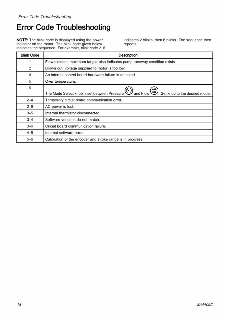
Error Code Troubleshooting
ErrorErrorError CodeCodeCode TroubleshootingTroubleshootingTroubleshootingNOTE:NOTE:NOTE: The blink code is displayed using the powerindicator on the motor. The blink code given belowindicates the sequence. For example, blink code 2–6
indicates 2 blinks, then 6 blinks. The sequence thenrepeats.
BlinkBlinkBlink CodeCodeCode DescriptionDescriptionDescription
1 Flow exceeds maximum target; also indicates pump runaway condition exists.
2 Brown out; voltage supplied to motor is too low.
4 An internal control board hardware failure is detected.
5 Over temperature.
6The Mode Select knob is set between Pressure and Flow . Set knob to the desired mode.
2–4 Temporary circuit board communication error.
2–6 AC power is lost.
3–5 Internal thermistor disconnected.
3–4 Software versions do not match.
3–6 Circuit board communication failure.
4–5 Internal software error.
5–6 Calibration of the encoder and stroke range is in progress.
18 3A4409C

Accessories
AccessoriesAccessoriesAccessoriesMotorMotorMotor PartPartPart No.No.No. DescriptionDescriptionDescription KitsKitsKits KitKitKit DescriptionDescriptionDescription
Models EM10X2and EM10X5
E-Flo DC Advanced Motors 17V232 Control Module, for Advanced Motors; seemanual 3A2527.
Models EM10X4and EM10X6
E-Flo DC Advanced Motors 17V233 Control Module, for Advanced Motors; seemanual 3A2527.
16P911 CAN Cable, 3 ft (1 m)Models EM10X2,EM10X4,EM10X5, andEM10X6
E-Flo DC Advanced Motors
16P912 CAN Cable, 25 ft (8 m)
288203 For 3000 and 4000 cc 4–Ball Lowers
288204 For Dura-Flo 1800 and 2400 Lowers
288205 For Dura-Flo 600, 750, 900, and 1200 Lowers
288206 For Dura-Flo 1000 Lowers
288207 For Xtreme 145, 180, 220, 250, and 290 Lowers
288209 For 750, 1000, 1500, and 2000 cc 4–Ball Lowerswith Enclosed or Open Wet Cup
288860 For Xtreme 85 and 115 Lowers
All motors in thismanual
Connection kits, to mount anE-Flo DC Motor to an existingpump lower. Kits include tierods, tie rod nuts, adapter, andcoupler.
17K525 For 750, 1000, 1500, and 2000 cc Sealed 4–BallLowers
255143 Wall Mounting KitAll motors in thismanual
Mounting kits
253692 Floor Stand
3A4409C 19
Appendix A - System Control Drawing 24Z541
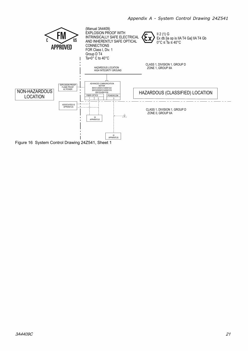
AppendixAppendixAppendix AAA --- SystemSystemSystem ControlControlControl DrawingDrawingDrawing 24Z54124Z54124Z541NOTESNOTESNOTES FORFORFOR FIG.FIG.FIG. 161616 ANDANDAND 17:17:17:
1. The non-intrinsically safe terminals (power rail)must not be connected to any device which usesor generates more than Um = 500 Vrms or DCunless it has been determined that the voltagehas been adequately isolated.
2. Do not remove any cover until power has beenremoved.
3. Installation in the U.S.A. must be in accordancewith ANSI/ISA RP12.06.01, installation ofintrinsically safe systems for hazardous(classified) locations, and the National ElectricalCode (ANSI/NFPA 70).
4. Installation in Canada must be in accordancewith the Canadian Electrical Code, CSA C22.1,Part 1, Appendix F.
5. For ATEX, install according to EN 60079–14 andapplicable local and national codes.
6. For IECEx, install according to IEC 60079–14and applicable local and national codes.
7. For installation, maintenance, or operationinstructions, see the instruction manual.
WARNING:WARNING:WARNING: Substitution of components mayimpair intrinsic safety.
ADVERTISSEMENT:ADVERTISSEMENT:ADVERTISSEMENT: La substitution decomposants peut compromettre la securiteintrinseque.
8. 8 Graco CAN cable part numbers 16P911,16P912.
9. The output entity parameters given for pins 1and 4 in port 3 are the total current and poweravailable to both pins added together. Thecurrent on pin 1 and pin 4 added together will notexceed the listed Io, and the power output frompin 1 and pin 4 added together will not exceedthe listed Po.
10. The intrinsically safe electrical outputs providedby the associated apparatus are not isolatedfrom earth.
11. The control drawing of the intrinsically safeapparatus must specify that the intrinsically safeapparatus provides internal isolation betweenCAN power and CAN Hi/CAN Lo circuits andconnections.
12. The specified Co and Lo values already includeconsideration of the effects of capacitance andinductance in combination.
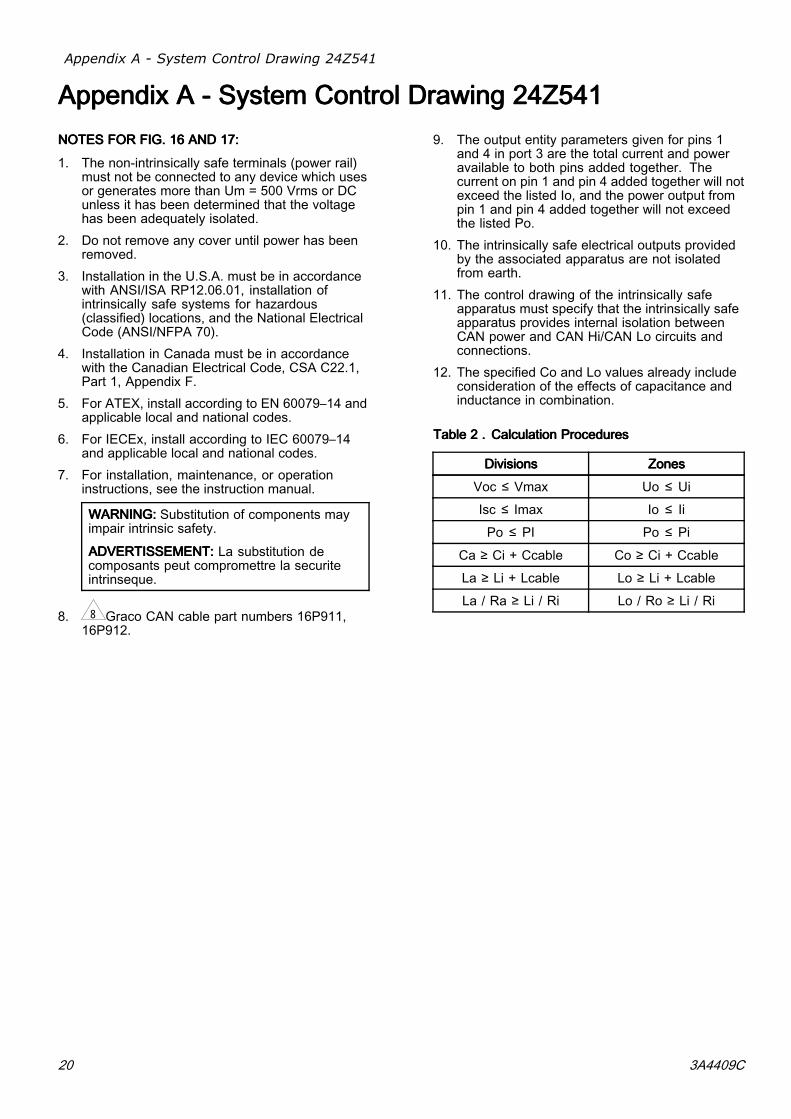
TableTableTable 222 ... CalculationCalculationCalculation ProceduresProceduresProcedures
DivisionsDivisionsDivisions ZonesZonesZones
Voc ≤ Vmax Uo ≤ Ui
Isc ≤ Imax Io ≤ Ii
Po ≤ PI Po ≤ Pi
Ca ≥ Ci + Ccable Co ≥ Ci + Ccable
La ≥ Li + Lcable Lo ≥ Li + Lcable
La / Ra ≥ Li / Ri Lo / Ro ≥ Li / Ri
20 3A4409C
Appendix A - System Control Drawing 24Z541
FIBER OPTICS POWER/COM1 32
ADVANCED COMMUNICATIONMOTOR
EM1012/EM1015/EM1022EM1025/EM1014/EM1016
EM1024/EM1026
HAZARDOUS LOCATIONHIGH INTEGRITY GROUND
EXPLOSION PROOFFLAME PROOF
AC POWER
NON-HAZARDOUSLOCATION
ISAPPARATUS
ASSOCIATED ISAPPARATUS
HAZARDOUS (CLASSIFIED) LOCATION
(Manual 3A4409)EXPLOSION PROOF WITH INTRINSICALLY SAFE ELECTRICALAND INHERENTLY SAFE OPTICAL CONNECTIONSFOR Class I, Div. 1Group D T4Ta=0° C to 40°C
ISAPPARATUS
II 2 (1) GEx db [ia op is IIA T4 Ga] IIA T4 Gb 0°C ≤ Ta ≤ 40°C
CLASS 1, DIVISION 1, GROUP D ZONE 0, GROUP IIA
CLASS 1, DIVISION 1, GROUP D ZONE 1, GROUP IIA
8
Figure 16 System Control Drawing 24Z541, Sheet 1
3A4409C 21

Appendix A - System Control Drawing 24Z541
Figure 17 System Control Drawing 24Z541, Sheet 2
TableTableTable 333 ... PortPortPort 3:3:3: PowerPowerPower BarrierBarrierBarrier OutputOutputOutput ParametersParametersParameters
CANCANCAN DataDataData High/LowHigh/LowHigh/Low ——— OutputOutputOutput BarriersBarriersBarriers
UoUoUo IoIoIo PoPoPo LoLoLo CoCoCo Lo/RoLo/RoLo/Ro
VocVocVoc IscIscIsc PtPtPt LaLaLa CaCaCa La/RaLa/RaLa/RaPinPinPin
UnitsUnitsUnits VVV mAmAmA mWmWmW μHμHμH μFμFμF μH/OhmμH/OhmμH/Ohm
1 CAN Data Low 4.94 63.3 79 709 999 36.39
2 Power 17.85 460 2893 116 2.5 98
3 IS GroundReturn
— — — — — —
4 CAN DataHigh
4.94 63.3 79 709 999 36.39
PortPortPort 3:3:3: MaleMaleMale M12M12M12555 PinPinPin “A”“A”“A” KeyKeyKey
5 Shield — — — — — —
22 3A4409C
Mounting Hole Pattern
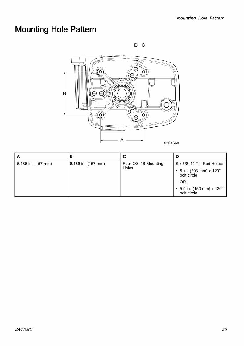
MountingMountingMounting HoleHoleHole PatternPatternPattern
AAA BBB CCC DDD
6.186 in. (157 mm) 6.186 in. (157 mm) Four 3/8–16 MountingHoles
Six 5/8–11 Tie Rod Holes:
• 8 in. (203 mm) x 120°bolt circleOR
• 5.9 in. (150 mm) x 120°bolt circle
3A4409C 23

Technical Specifications
TechnicalTechnicalTechnical SpecificationsSpecificationsSpecificationsEEE---FloFloFlo DCDCDC MotorsMotorsMotors U.S.U.S.U.S. MetricMetricMetricInputInputInput voltage/Power:voltage/Power:voltage/Power:
Models EM101x 380–480 VAC three phase, 50/60 Hz, 1.5 kVAModels EM102x 380–480 VAC three phase, 50/60 Hz, 3.0 kVA
MaximumMaximumMaximum potentialpotentialpotential fluidfluidfluidpressure:pressure:pressure:
Models EM101x 218000/v (volume of lower in cc) = psi 1500/v (volume of lower in cc) = barModels EM102x 500000/v (volume of lower in cc) = psi 3440/v (volume of lower in cc) = bar
Maximum continuous cyclerate
20 cpm
MaximumMaximumMaximum force:force:force:Models EM101x 1400 lbf 6227 NModels EM102x 3500 lbf 15570 N
Power inlet port size 3/4–14 npt(f)Ambient temperaturerange
32–104°F 0–40°C
Sound data Less than 70 dB(A)Oil capacity 1.5 quarts 1.4 litersOil specification Graco Part No. 16W645
ISO 220 silicone-free high-pressure synthetic gear oilWeight 99 lb 45 kg
24 3A4409C

Notes
NotesNotesNotes
3A4409C 25
GracoGracoGraco StandardStandardStandard WarrantyWarrantyWarranty
Graco warrants all equipment referenced in this document which is manufactured by Graco andbearing its name to be free from defects in material and workmanship on the date of sale to the originalpurchaser for use. With the exception of any special, extended, or limited warranty published byGraco, Graco will, for a period of twelve months from the date of sale, repair or replace any part of theequipment determined by Graco to be defective. This warranty applies only when the equipment isinstalled, operated and maintained in accordance with Graco’s written recommendations.This warranty does not cover, and Graco shall not be liable for general wear and tear, or anymalfunction, damage or wear caused by faulty installation, misapplication, abrasion, corrosion,inadequate or improper maintenance, negligence, accident, tampering, or substitution of non-Gracocomponent parts. Nor shall Graco be liable for malfunction, damage or wear caused by theincompatibility of Graco equipment with structures, accessories, equipment or materials not suppliedby Graco, or the improper design, manufacture, installation, operation or maintenance of structures,accessories, equipment or materials not supplied by Graco.This warranty is conditioned upon the prepaid return of the equipment claimed to be defective to anauthorized Graco distributor for verification of the claimed defect. If the claimed defect is verified,Graco will repair or replace free of charge any defective parts. The equipment will be returned tothe original purchaser transportation prepaid. If inspection of the equipment does not disclose anydefect in material or workmanship, repairs will be made at a reasonable charge, which charges mayinclude the costs of parts, labor, and transportation.THIS WARRANTY IS EXCLUSIVE, AND IS IN LIEU OF ANY OTHER WARRANTIES, EXPRESSOR IMPLIED, INCLUDING BUT NOT LIMITED TO WARRANTY OF MERCHANTABILITY ORWARRANTY OF FITNESS FOR A PARTICULAR PURPOSE.Graco’s sole obligation and buyer’s sole remedy for any breach of warranty shall be as set forth above.The buyer agrees that no other remedy (including, but not limited to, incidental or consequentialdamages for lost profits, lost sales, injury to person or property, or any other incidental or consequentialloss) shall be available. Any action for breach of warranty must be brought within two (2) years ofthe date of sale.GRACOGRACOGRACO MAKESMAKESMAKES NONONO WARRANTY,WARRANTY,WARRANTY, ANDANDAND DISCLAIMSDISCLAIMSDISCLAIMS ALLALLALL IMPLIEDIMPLIEDIMPLIED WARRANTIESWARRANTIESWARRANTIES OFOFOFMERCHANTABILITYMERCHANTABILITYMERCHANTABILITY ANDANDAND FITNESSFITNESSFITNESS FORFORFOR AAA PARTICULARPARTICULARPARTICULAR PURPOSE,PURPOSE,PURPOSE, INININ CONNECTIONCONNECTIONCONNECTION WITHWITHWITHACCESSORIES,ACCESSORIES,ACCESSORIES, EQUIPMENT,EQUIPMENT,EQUIPMENT, MATERIALSMATERIALSMATERIALS OROROR COMPONENTSCOMPONENTSCOMPONENTS SOLDSOLDSOLD BUTBUTBUT NOTNOTNOTMANUFACTUREDMANUFACTUREDMANUFACTUREDBYBYBY GRACO.GRACO.GRACO. These items sold, but not manufactured by Graco (such as electric motors, switches,hose, etc.), are subject to the warranty, if any, of their manufacturer. Graco will provide purchaser withreasonable assistance in making any claim for breach of these warranties.In no event will Graco be liable for indirect, incidental, special or consequential damages resultingfrom Graco supplying equipment hereunder, or the furnishing, performance, or use of any products orother goods sold hereto, whether due to a breach of contract, breach of warranty, the negligence ofGraco, or otherwise.FOR GRACO CANADA CUSTOMERSThe Parties acknowledge that they have required that the present document, as well as all documents,notices and legal proceedings entered into, given or instituted pursuant hereto or relating directly orindirectly hereto, be drawn up in English. Les parties reconnaissent avoir convenu que la rédactiondu présente document sera en Anglais, ainsi que tous documents, avis et procédures judiciairesexécutés, donnés ou intentés, à la suite de ou en rapport, directement ou indirectement, avec lesprocédures concernées.
GracoGracoGraco InformationInformationInformationFor the latest information about Graco products, visit www.graco.com. For patent information, seewww.graco.com/patents.ToToTo placeplaceplace ananan order,order,order, contact your Graco Distributor or call to identify the nearest distributor.Phone:Phone:Phone: 612-623-6921 ororor TollTollToll Free:Free:Free: 1-800-328-0211 Fax:Fax:Fax: 612-378-3505
All written and visual data contained in this document reflects the latest product information available at the time of publication.Graco reserves the right to make changes at any time without notice.Original Instructions. This manual contains English, MM 3A4409
GracoGracoGraco Headquarters:Headquarters:Headquarters: Minneapolis
InternationalInternationalInternational Offices:Offices:Offices: Belgium, China, Japan, Korea
GRACOGRACOGRACO INC.INC.INC. ANDANDAND SUBSIDIARIESSUBSIDIARIESSUBSIDIARIES ••• P.O.P.O.P.O. BOXBOXBOX 144114411441 ••• MINNEAPOLIS,MINNEAPOLIS,MINNEAPOLIS, MNMNMN 55440-144155440-144155440-1441 ••• USAUSAUSACopyrightCopyrightCopyright 2018,2018,2018, GracoGracoGraco Inc.Inc.Inc. AllAllAll GracoGracoGraco manufacturingmanufacturingmanufacturing locationslocationslocations areareare registeredregisteredregistered tototo ISOISOISO 9001.9001.9001.
www.graco.comRevision C, March 2018