3d dragonfly model process book
DESCRIPTION
This is the process book on how I made a wind-up dragonfly in Autodesk Maya. And I got a blog on my research: http://lawht-3d2010.blogspot.hk/TRANSCRIPT
1) Making of the dragonfly model (overall process)
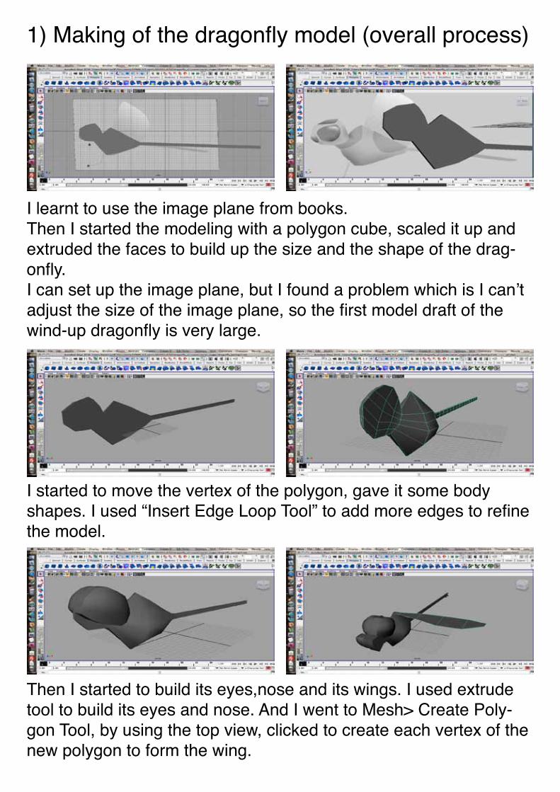
I learnt to use the image plane from books. Then I started the modeling with a polygon cube, scaled it up and extruded the faces to build up the size and the shape of the drag-onfly.I can set up the image plane, but I found a problem which is I can’t adjust the size of the image plane, so the first model draft of the wind-up dragonfly is very large.
I started to move the vertex of the polygon, gave it some body shapes. I used “Insert Edge Loop Tool” to add more edges to refine the model.
Then I started to build its eyes,nose and its wings. I used extrude tool to build its eyes and nose. And I went to Mesh> Create Poly-gon Tool, by using the top view, clicked to create each vertex of the new polygon to form the wing.
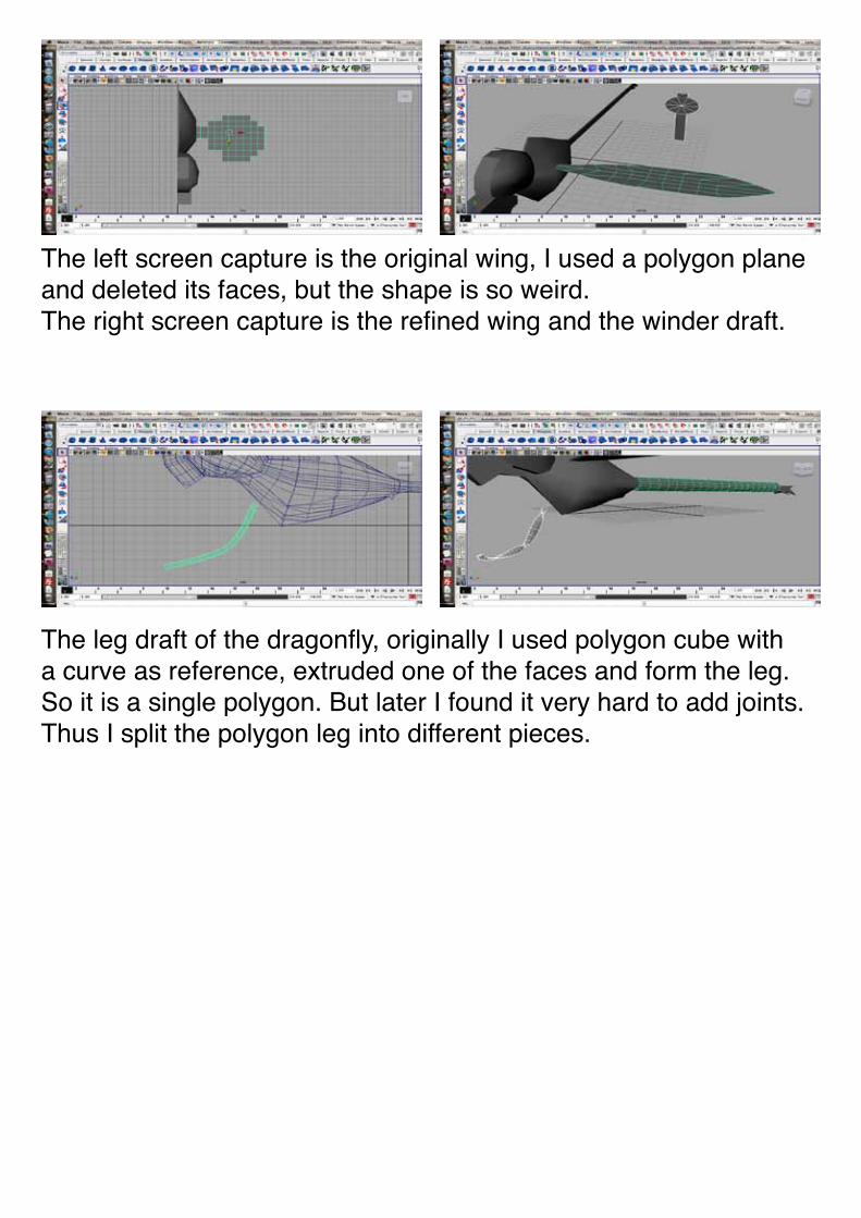
The left screen capture is the original wing, I used a polygon plane and deleted its faces, but the shape is so weird.The right screen capture is the refined wing and the winder draft.
The leg draft of the dragonfly, originally I used polygon cube with a curve as reference, extruded one of the faces and form the leg. So it is a single polygon. But later I found it very hard to add joints. Thus I split the polygon leg into different pieces.
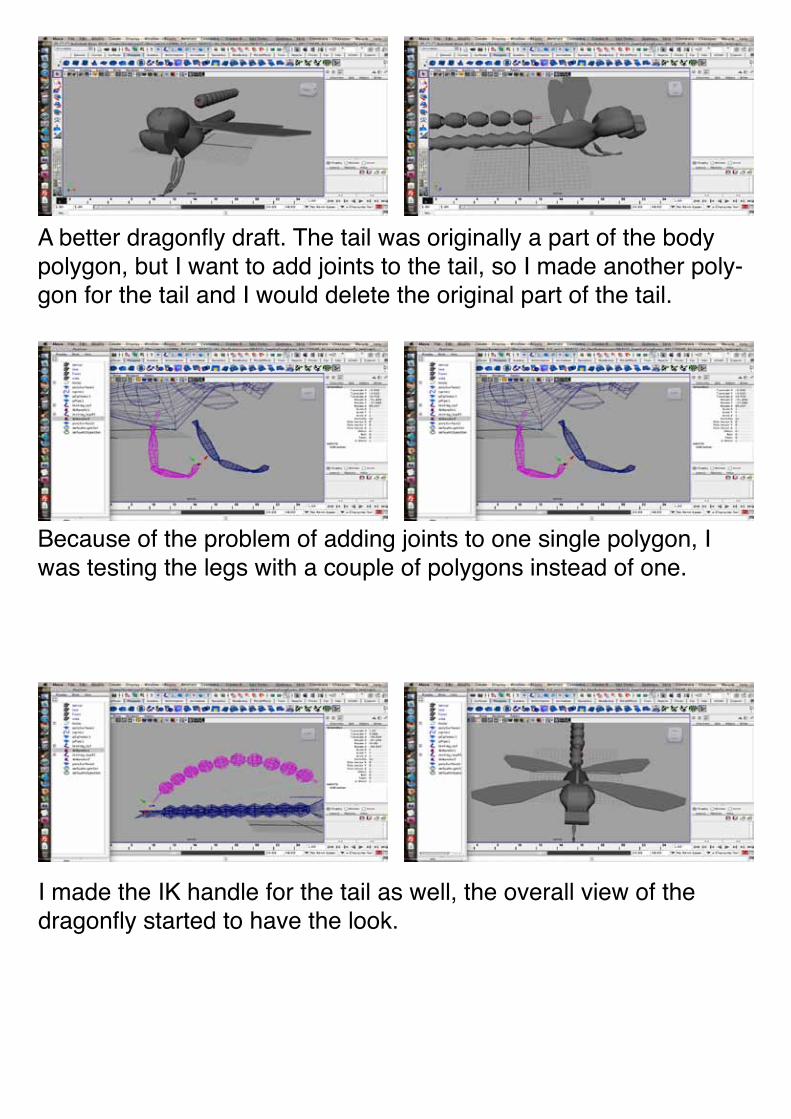
A better dragonfly draft. The tail was originally a part of the body polygon, but I want to add joints to the tail, so I made another poly-gon for the tail and I would delete the original part of the tail.
Because of the problem of adding joints to one single polygon, I was testing the legs with a couple of polygons instead of one.
I made the IK handle for the tail as well, the overall view of the dragonfly started to have the look.
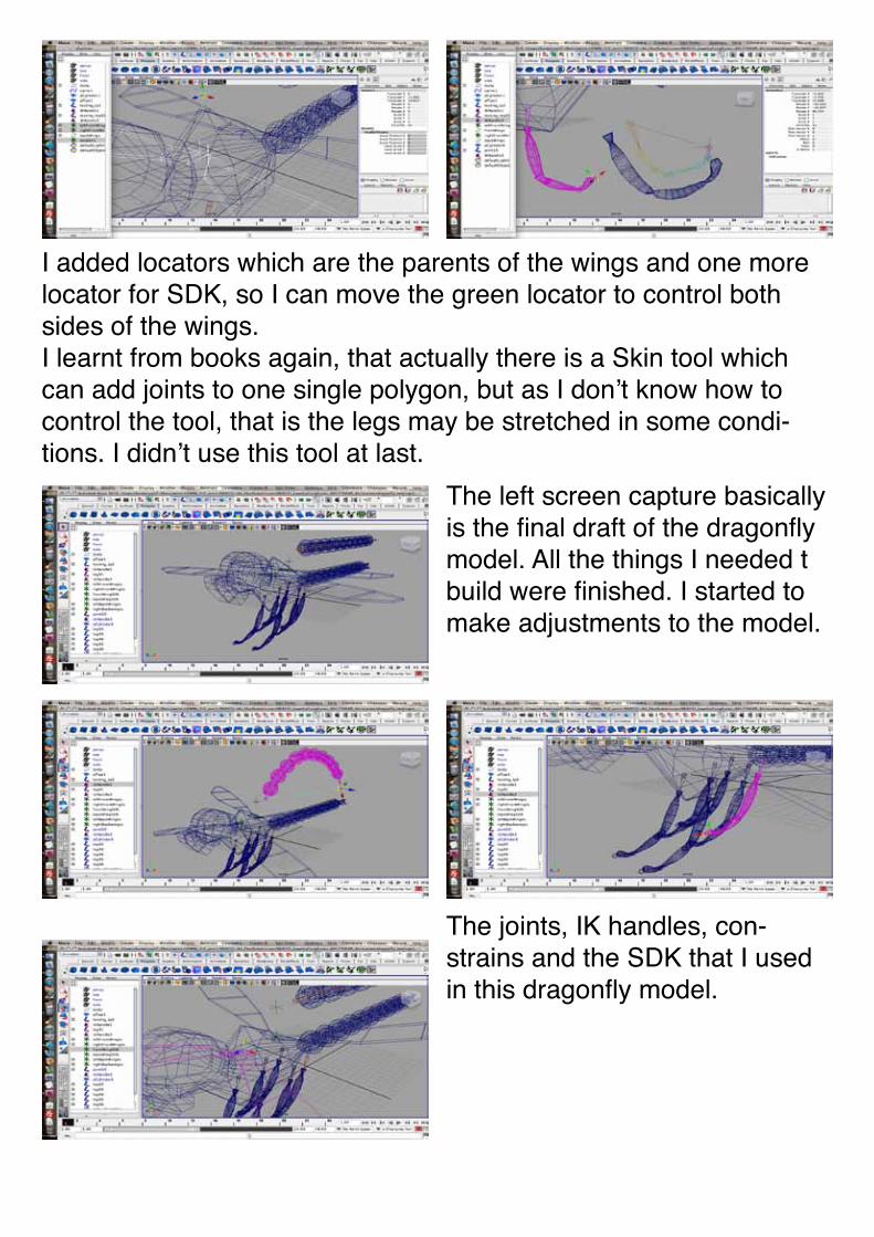
I added locators which are the parents of the wings and one more locator for SDK, so I can move the green locator to control both sides of the wings.I learnt from books again, that actually there is a Skin tool which can add joints to one single polygon, but as I don’t know how to control the tool, that is the legs may be stretched in some condi-tions. I didn’t use this tool at last.
The left screen capture basically is the final draft of the dragonfly model. All the things I needed t build were finished. I started to make adjustments to the model.
The joints, IK handles, con-strains and the SDK that I used in this dragonfly model.
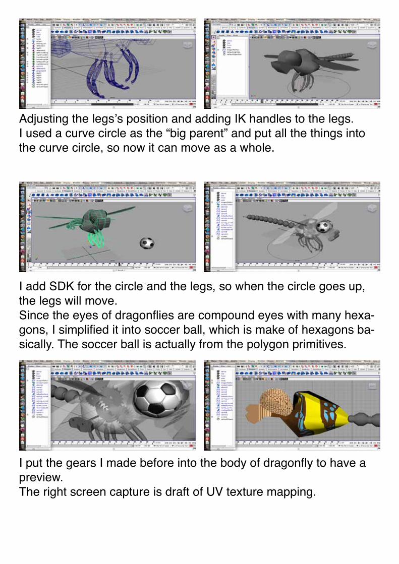
Adjusting the legs’s position and adding IK handles to the legs.I used a curve circle as the “big parent” and put all the things into the curve circle, so now it can move as a whole.
I add SDK for the circle and the legs, so when the circle goes up, the legs will move.Since the eyes of dragonflies are compound eyes with many hexa-gons, I simplified it into soccer ball, which is make of hexagons ba-sically. The soccer ball is actually from the polygon primitives.
I put the gears I made before into the body of dragonfly to have a preview.The right screen capture is draft of UV texture mapping.
It comes to the part of animation. This is the motion path that I did tests on to see if it works well with the dragonfly.
I changed the textures used, this one is close to the final one.
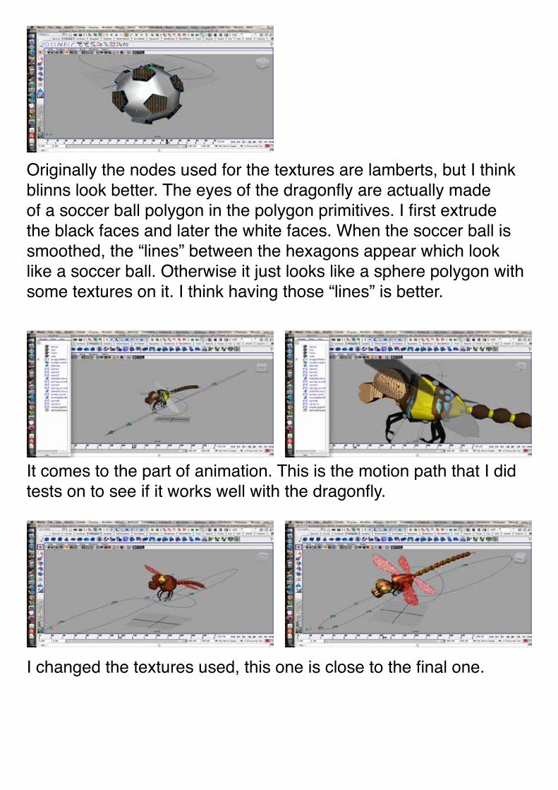
Originally the nodes used for the textures are lamberts, but I think blinns look better. The eyes of the dragonfly are actually made of a soccer ball polygon in the polygon primitives. I first extrude the black faces and later the white faces. When the soccer ball is smoothed, the “lines” between the hexagons appear which look like a soccer ball. Otherwise it just looks like a sphere polygon with some textures on it. I think having those “lines” is better.
The building of the scene, this is the whole up, the process of mak-ing of this scene will be explained later.
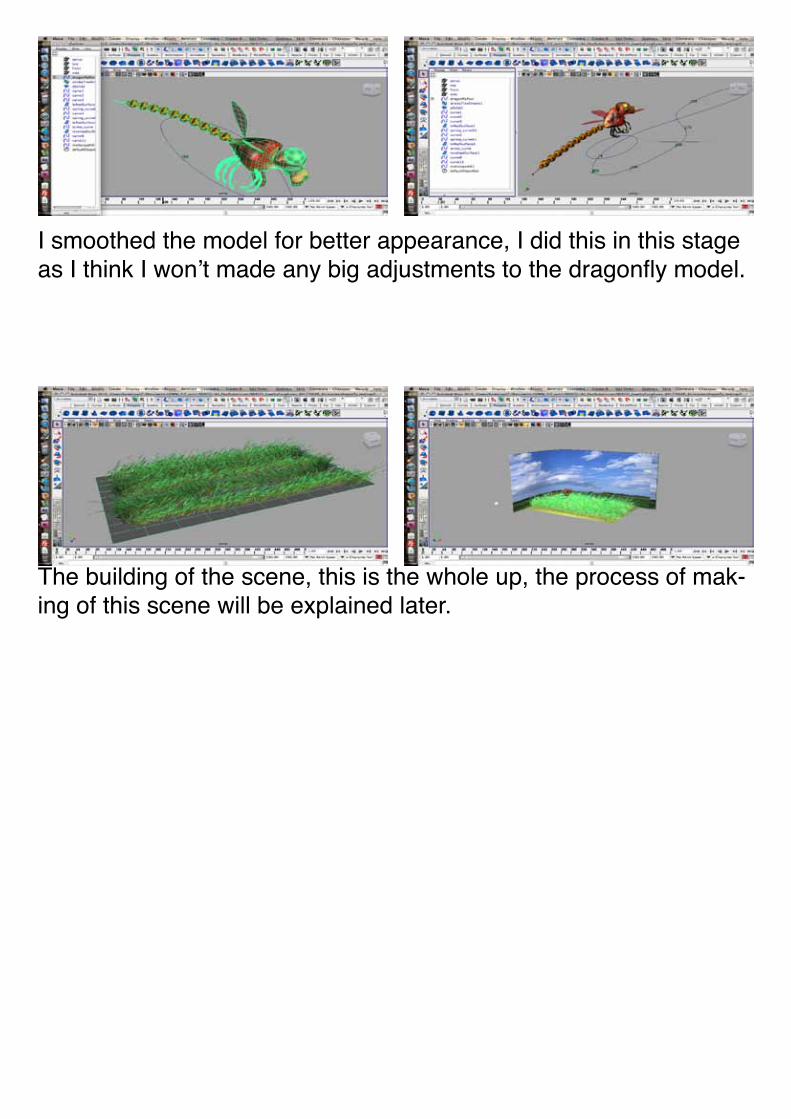
I smoothed the model for better appearance, I did this in this stage as I think I won’t made any big adjustments to the dragonfly model.
In the process of making the model, there are still some difficul-ties that I cannot solve. I have some solutions for some difficulties, though I believe there must be better ways to solve them.
2) Making of gears
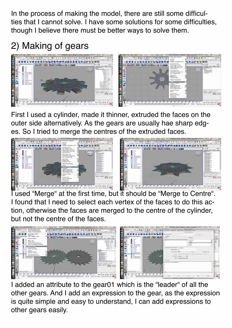
First I used a cylinder, made it thinner, extruded the faces on the outer side alternatively. As the gears are usually hae sharp edg-es. So I tried to merge the centres of the extruded faces.
I used “Merge“ at the first time, but it should be “Merge to Centre“. I found that I need to select each vertex of the faces to do this ac-tion, otherwise the faces are merged to the centre of the cylinder, but not the centre of the faces.
I added an attribute to the gear01 which is the “leader“ of all the other gears. And I add an expression to the gear, as the expression is quite simple and easy to understand, I can add expressions to other gears easily.
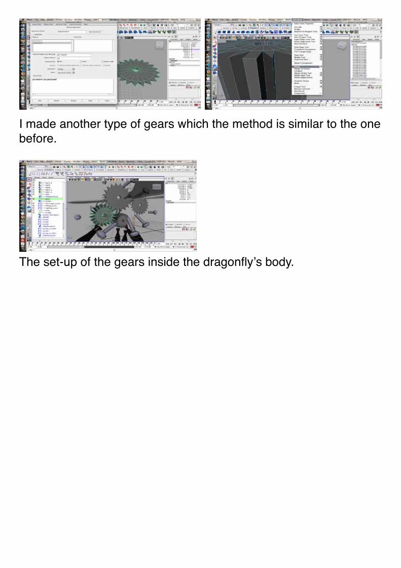
I made another type of gears which the method is similar to the one before.
The set-up of the gears inside the dragonfly’s body.
3) Making of screws
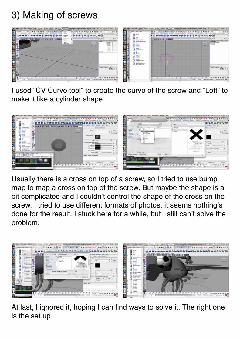
I used “CV Curve tool“ to create the curve of the screw and “Loft“ to make it like a cylinder shape.
Usually there is a cross on top of a screw, so I tried to use bump map to map a cross on top of the screw. But maybe the shape is a bit complicated and I couldn’t control the shape of the cross on the screw. I tried to use different formats of photos, it seems nothing’s done for the result. I stuck here for a while, but I still can’t solve the problem.
At last, I ignored it, hoping I can find ways to solve it. The right one is the set up.
4) Making of axis of the gears
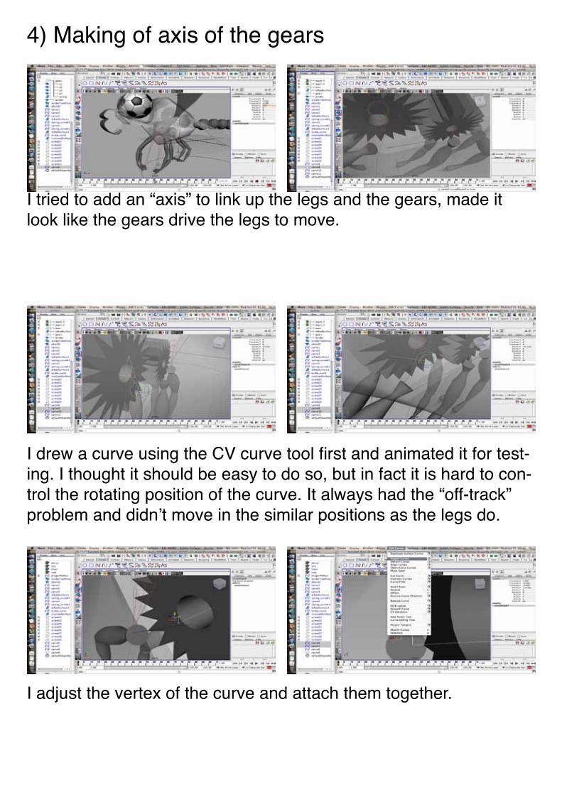
I tried to add an “axis” to link up the legs and the gears, made it look like the gears drive the legs to move.
I drew a curve using the CV curve tool first and animated it for test-ing. I thought it should be easy to do so, but in fact it is hard to con-trol the rotating position of the curve. It always had the “off-track” problem and didn’t move in the similar positions as the legs do.
I adjust the vertex of the curve and attach them together.
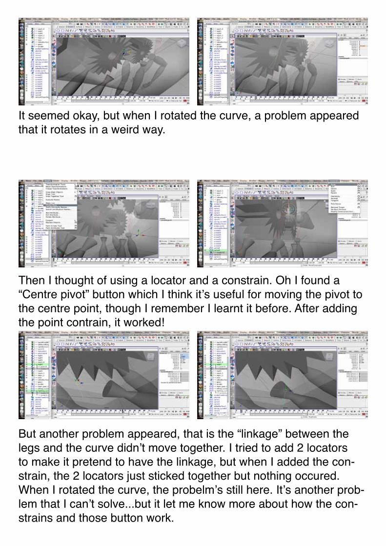
It seemed okay, but when I rotated the curve, a problem appeared that it rotates in a weird way.
Then I thought of using a locator and a constrain. Oh I found a “Centre pivot” button which I think it’s useful for moving the pivot to the centre point, though I remember I learnt it before. After adding the point contrain, it worked!
But another problem appeared, that is the “linkage” between the legs and the curve didn’t move together. I tried to add 2 locators to make it pretend to have the linkage, but when I added the con-strain, the 2 locators just sticked together but nothing occured. When I rotated the curve, the probelm’s still here. It’s another prob-lem that I can’t solve...but it let me know more about how the con-strains and those button work.
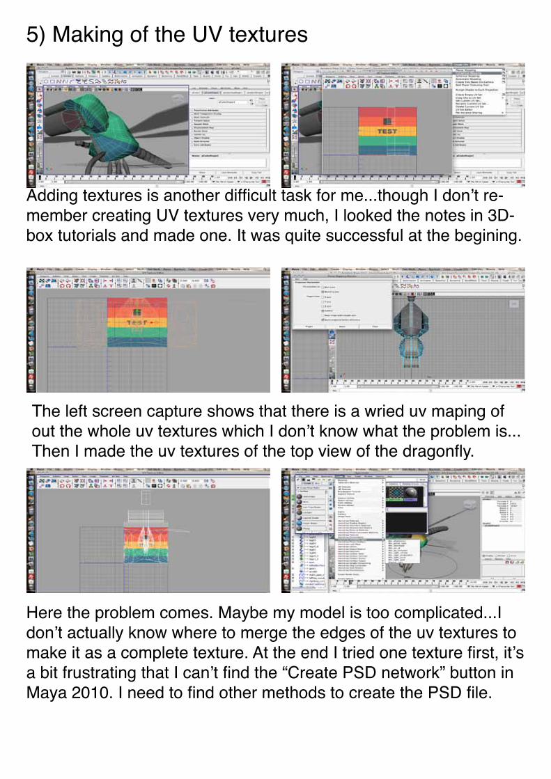
5) Making of the UV textures
Adding textures is another difficult task for me...though I don’t re-member creating UV textures very much, I looked the notes in 3D-box tutorials and made one. It was quite successful at the begining.
The left screen capture shows that there is a wried uv maping of out the whole uv textures which I don’t know what the problem is...Then I made the uv textures of the top view of the dragonfly.
Here the problem comes. Maybe my model is too complicated...I don’t actually know where to merge the edges of the uv textures to make it as a complete texture. At the end I tried one texture first, it’s a bit frustrating that I can’t find the “Create PSD network” button in Maya 2010. I need to find other methods to create the PSD file.
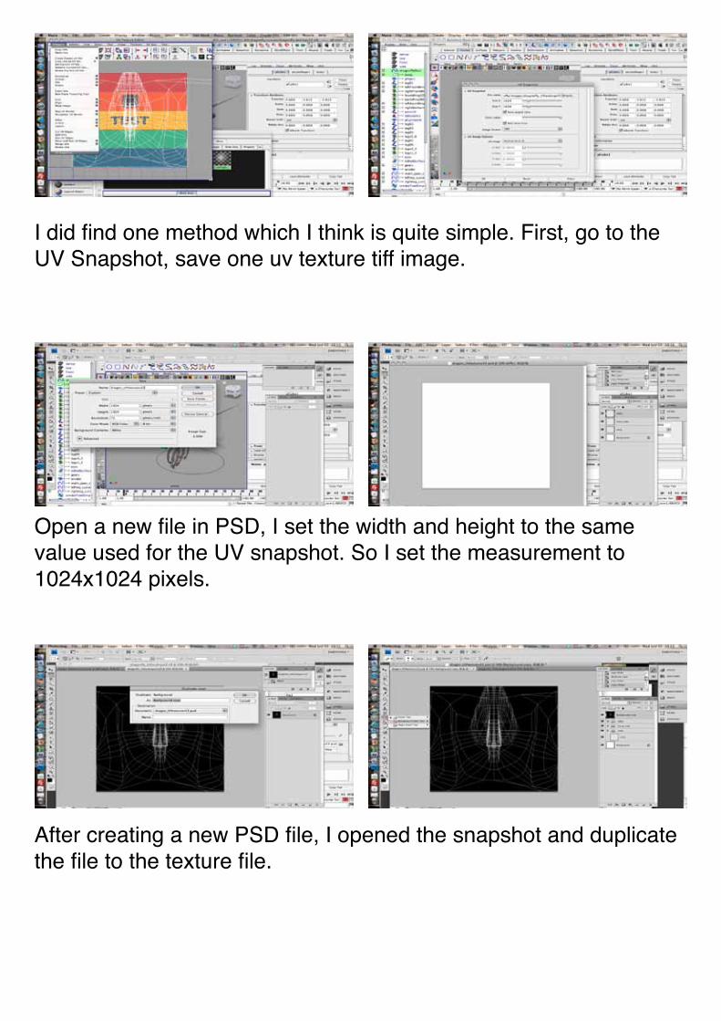
I did find one method which I think is quite simple. First, go to the UV Snapshot, save one uv texture tiff image.
Open a new file in PSD, I set the width and height to the same value used for the UV snapshot. So I set the measurement to 1024x1024 pixels.
After creating a new PSD file, I opened the snapshot and duplicate the file to the texture file.
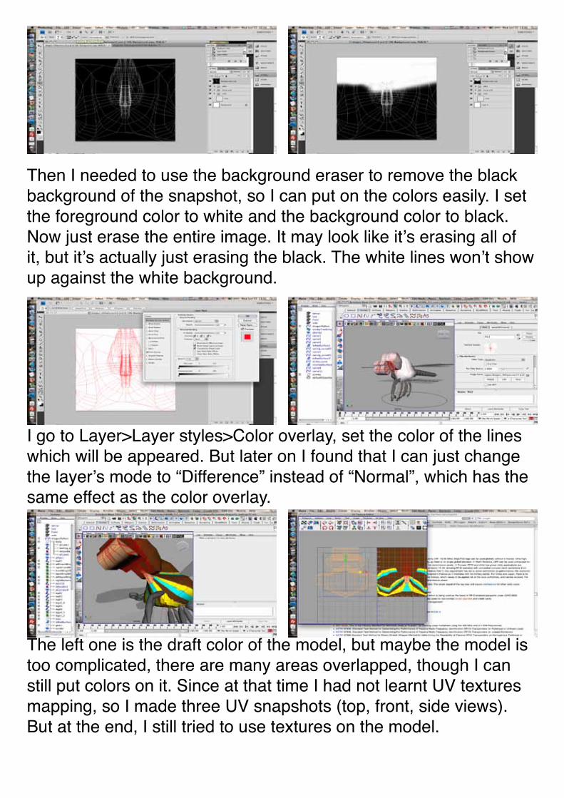
Then I needed to use the background eraser to remove the black background of the snapshot, so I can put on the colors easily. I set the foreground color to white and the background color to black. Now just erase the entire image. It may look like it’s erasing all of it, but it’s actually just erasing the black. The white lines won’t show up against the white background.
I go to Layer>Layer styles>Color overlay, set the color of the lines which will be appeared. But later on I found that I can just change the layer’s mode to “Difference” instead of “Normal”, which has the same effect as the color overlay.
The left one is the draft color of the model, but maybe the model is too complicated, there are many areas overlapped, though I can still put colors on it. Since at that time I had not learnt UV textures mapping, so I made three UV snapshots (top, front, side views). But at the end, I still tried to use textures on the model.
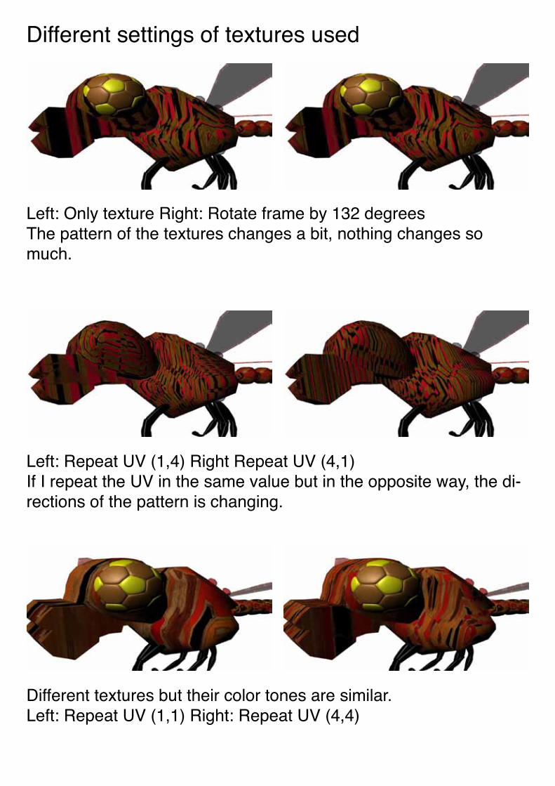
Different settings of textures used
Left: Only texture Right: Rotate frame by 132 degreesThe pattern of the textures changes a bit, nothing changes so much.
Left: Repeat UV (1,4) Right Repeat UV (4,1)If I repeat the UV in the same value but in the opposite way, the di-rections of the pattern is changing.
Different textures but their color tones are similar.Left: Repeat UV (1,1) Right: Repeat UV (4,4)
6) Making of spring
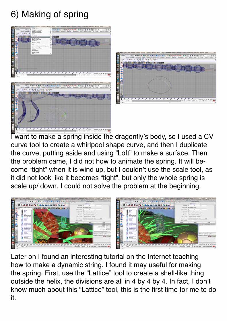
I want to make a spring inside the dragonfly’s body, so I used a CV curve tool to create a whirlpool shape curve, and then I duplicate the curve, putting aside and using “Loft” to make a surface. Then the problem came, I did not how to animate the spring. It will be-come “tight” when it is wind up, but I couldn’t use the scale tool, as it did not look like it becomes “tight”, but only the whole spring is scale up/ down. I could not solve the problem at the beginning.
Later on I found an interesting tutorial on the Internet teaching how to make a dynamic string. I found it may useful for making the spring. First, use the “Lattice” tool to create a shell-like thing outside the helix, the divisions are all in 4 by 4 by 4. In fact, I don’t know much about this “Lattice” tool, this is the first time for me to do it.
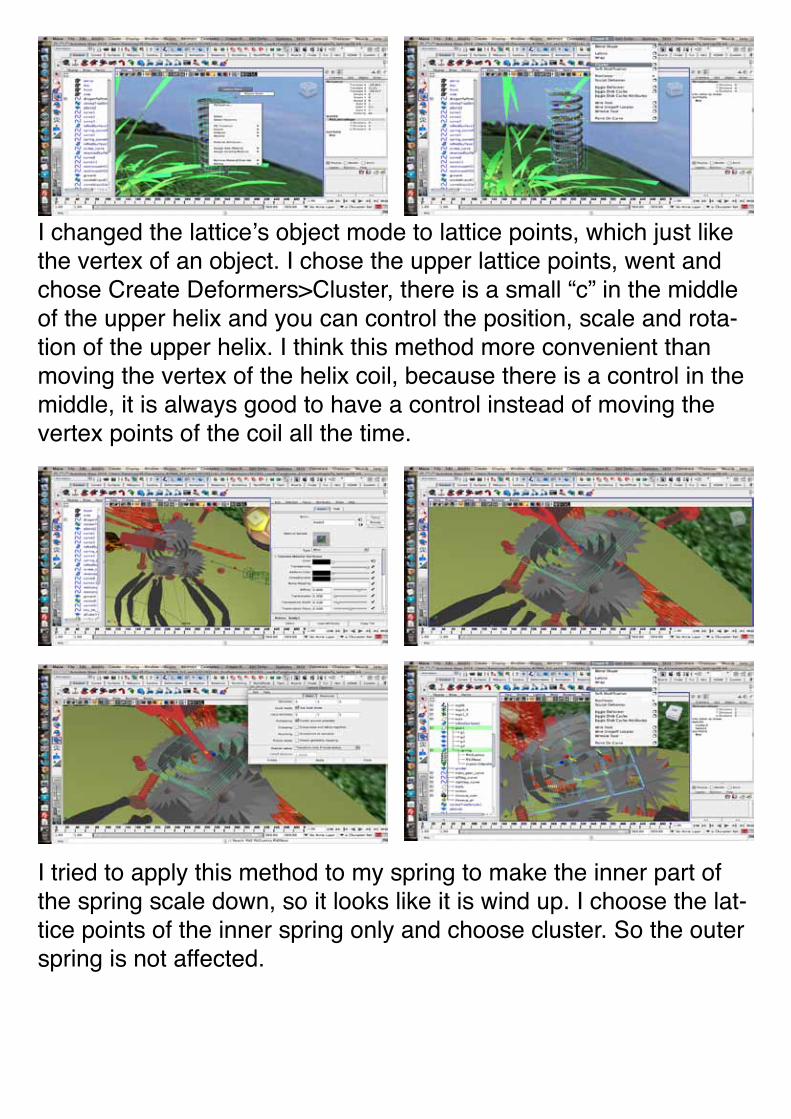
I changed the lattice’s object mode to lattice points, which just like the vertex of an object. I chose the upper lattice points, went and chose Create Deformers>Cluster, there is a small “c” in the middle of the upper helix and you can control the position, scale and rota-tion of the upper helix. I think this method more convenient than moving the vertex of the helix coil, because there is a control in the middle, it is always good to have a control instead of moving the vertex points of the coil all the time.
I tried to apply this method to my spring to make the inner part of the spring scale down, so it looks like it is wind up. I choose the lat-tice points of the inner spring only and choose cluster. So the outer spring is not affected.
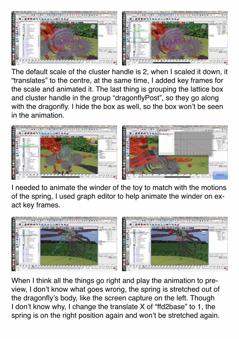
The default scale of the cluster handle is 2, when I scaled it down, it “translates” to the centre, at the same time, I added key frames for the scale and animated it. The last thing is grouping the lattice box and cluster handle in the group “dragonflyPost”, so they go along with the dragonfly. I hide the box as well, so the box won’t be seen in the animation.
When I think all the things go right and play the animation to pre-view, I don’t know what goes wrong, the spring is stretched out of the dragonfly’s body, like the screen capture on the left. Though I don’t know why, I change the translate X of “ffd2base” to 1, the spring is on the right position again and won’t be stretched again.
I needed to animate the winder of the toy to match with the motions of the spring, I used graph editor to help animate the winder on ex-act key frames.
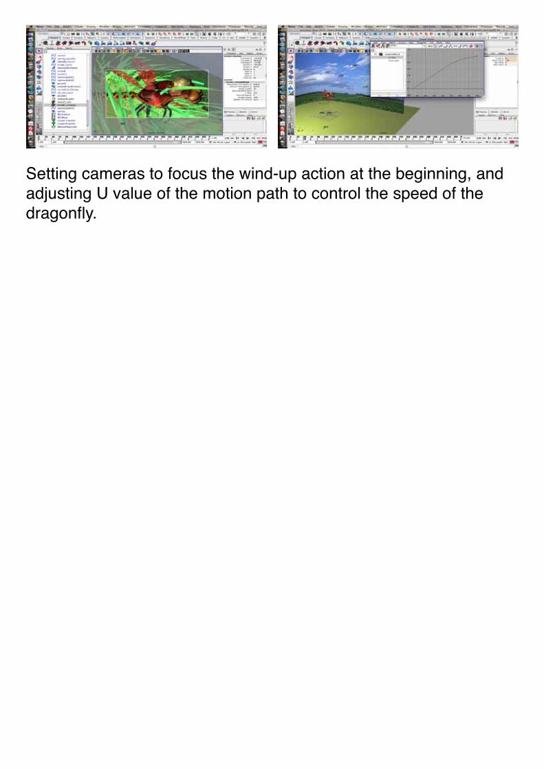
Setting cameras to focus the wind-up action at the beginning, and adjusting U value of the motion path to control the speed of the dragonfly.
7) Making of wings (key frames)
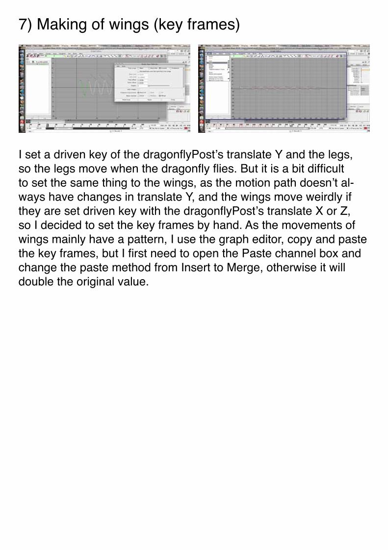
I set a driven key of the dragonflyPost’s translate Y and the legs, so the legs move when the dragonfly flies. But it is a bit difficult to set the same thing to the wings, as the motion path doesn’t al-ways have changes in translate Y, and the wings move weirdly if they are set driven key with the dragonflyPost’s translate X or Z, so I decided to set the key frames by hand. As the movements of wings mainly have a pattern, I use the graph editor, copy and paste the key frames, but I first need to open the Paste channel box and change the paste method from Insert to Merge, otherwise it will double the original value.
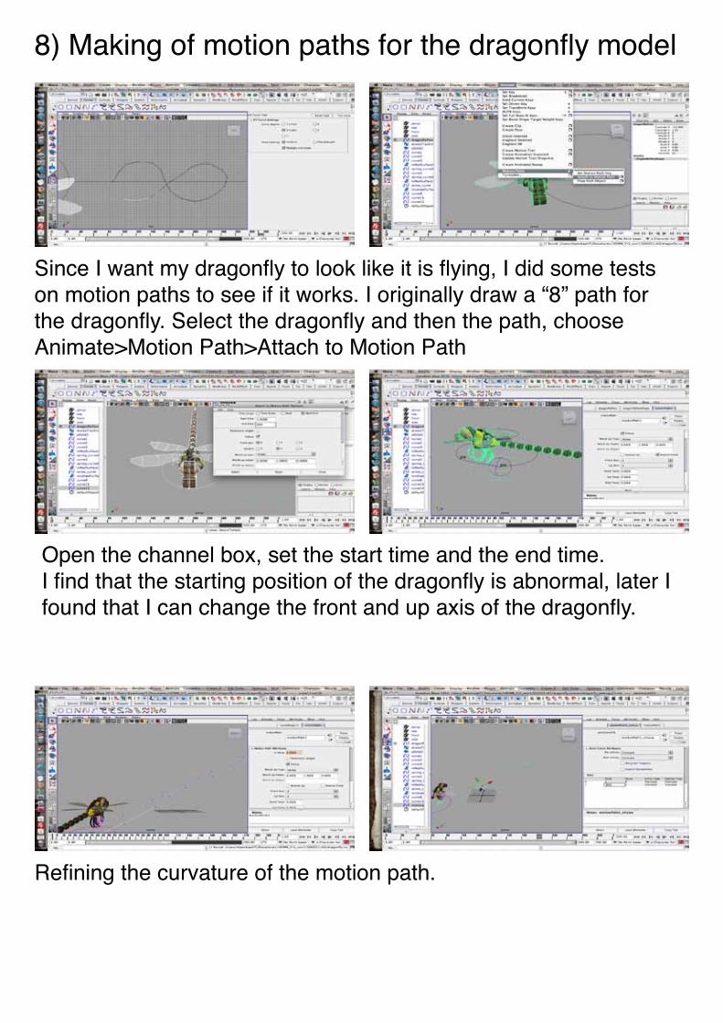
8) Making of motion paths for the dragonfly model
Since I want my dragonfly to look like it is flying, I did some tests on motion paths to see if it works. I originally draw a “8” path for the dragonfly. Select the dragonfly and then the path, choose Animate>Motion Path>Attach to Motion Path
Open the channel box, set the start time and the end time.I find that the starting position of the dragonfly is abnormal, later I found that I can change the front and up axis of the dragonfly.
Refining the curvature of the motion path.
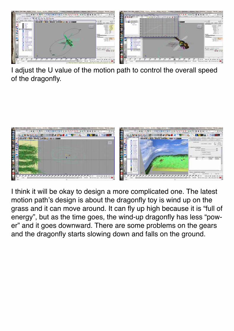
I adjust the U value of the motion path to control the overall speed of the dragonfly.
I think it will be okay to design a more complicated one. The latest motion path’s design is about the dragonfly toy is wind up on the grass and it can move around. It can fly up high because it is “full of energy”, but as the time goes, the wind-up dragonfly has less “pow-er” and it goes downward. There are some problems on the gears and the dragonfly starts slowing down and falls on the ground.
9) Building up the scene (making of the grass)
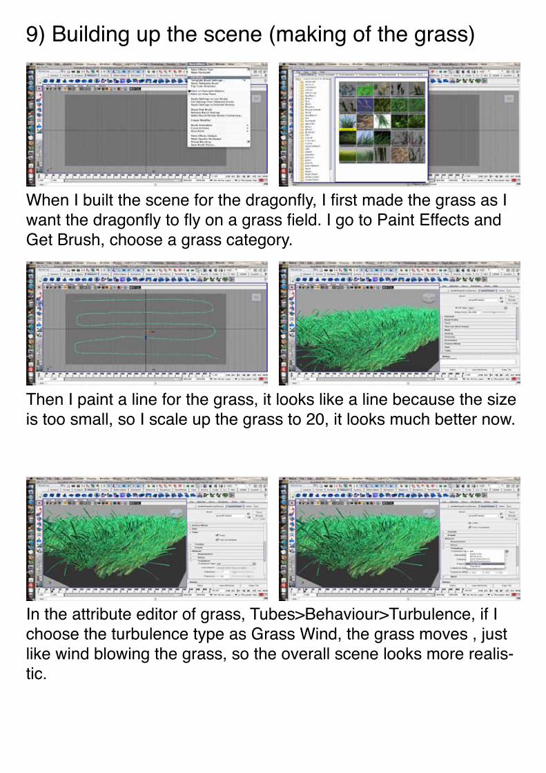
When I built the scene for the dragonfly, I first made the grass as I want the dragonfly to fly on a grass field. I go to Paint Effects and Get Brush, choose a grass category.
Then I paint a line for the grass, it looks like a line because the size is too small, so I scale up the grass to 20, it looks much better now.
In the attribute editor of grass, Tubes>Behaviour>Turbulence, if I choose the turbulence type as Grass Wind, the grass moves , just like wind blowing the grass, so the overall scene looks more realis-tic.
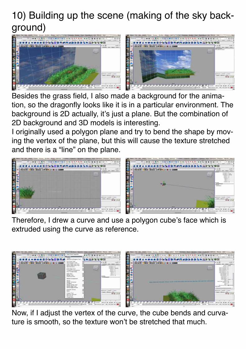
10) Building up the scene (making of the sky back-ground)
Besides the grass field, I also made a background for the anima-tion, so the dragonfly looks like it is in a particular environment. The background is 2D actually, it’s just a plane. But the combination of 2D background and 3D models is interesting.I originally used a polygon plane and try to bend the shape by mov-ing the vertex of the plane, but this will cause the texture stretched and there is a “line” on the plane.
Now, if I adjust the vertex of the curve, the cube bends and curva-ture is smooth, so the texture won’t be stretched that much.
Therefore, I drew a curve and use a polygon cube’s face which is extruded using the curve as reference.
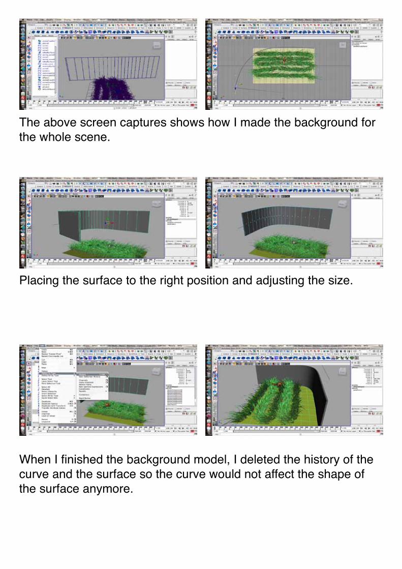
Placing the surface to the right position and adjusting the size.
The above screen captures shows how I made the background for the whole scene.
When I finished the background model, I deleted the history of the curve and the surface so the curve would not affect the shape of the surface anymore.
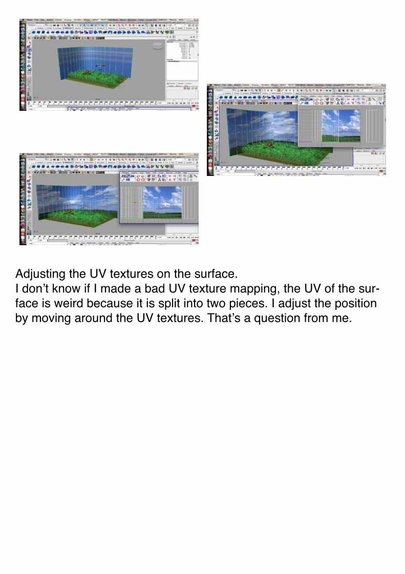
Adjusting the UV textures on the surface.I don’t know if I made a bad UV texture mapping, the UV of the sur-face is weird because it is split into two pieces. I adjust the position by moving around the UV textures. That’s a question from me.
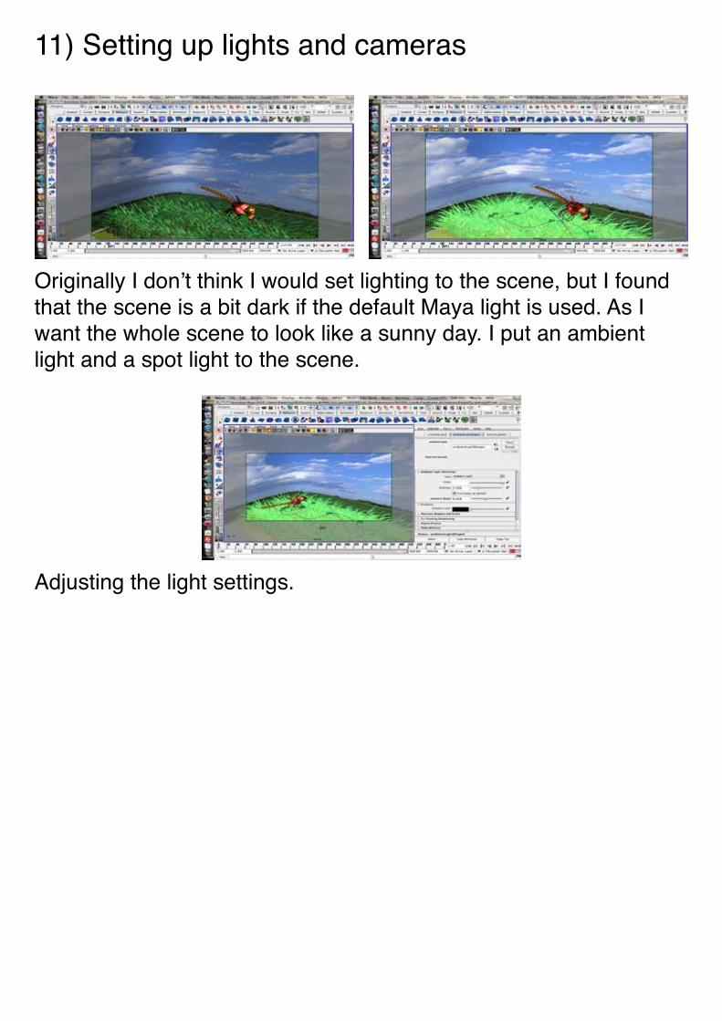
Originally I don’t think I would set lighting to the scene, but I found that the scene is a bit dark if the default Maya light is used. As I want the whole scene to look like a sunny day. I put an ambient light and a spot light to the scene.
Adjusting the light settings.
11) Setting up lights and cameras
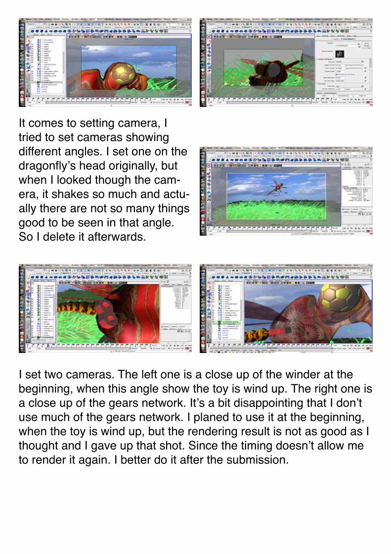
I set two cameras. The left one is a close up of the winder at the beginning, when this angle show the toy is wind up. The right one is a close up of the gears network. It’s a bit disappointing that I don’t use much of the gears network. I planed to use it at the beginning, when the toy is wind up, but the rendering result is not as good as I thought and I gave up that shot. Since the timing doesn’t allow me to render it again. I better do it after the submission.
It comes to setting camera, I tried to set cameras showing different angles. I set one on the dragonfly’s head originally, but when I looked though the cam-era, it shakes so much and actu-ally there are not so many things good to be seen in that angle. So I delete it afterwards.
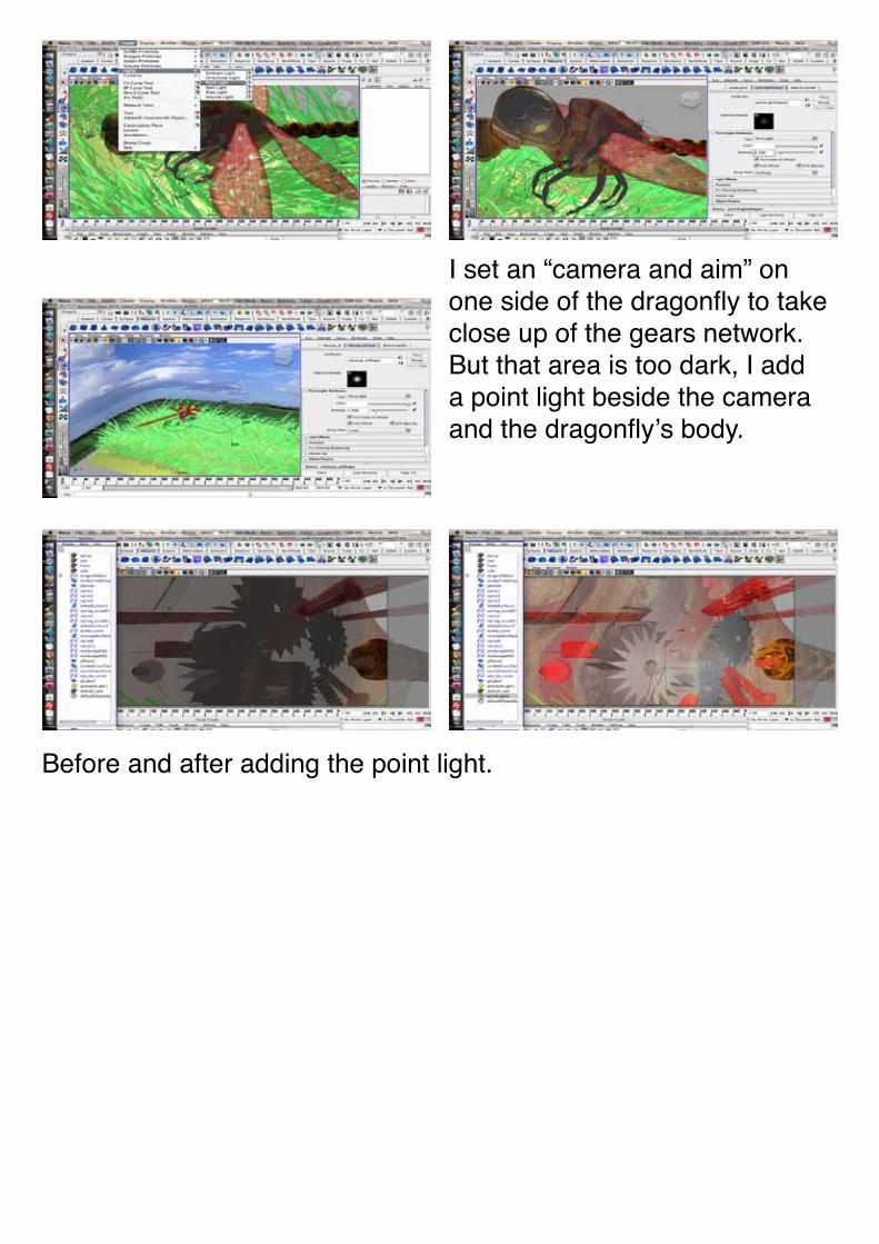
Before and after adding the point light.
I set an “camera and aim” on one side of the dragonfly to take close up of the gears network. But that area is too dark, I add a point light beside the camera and the dragonfly’s body.
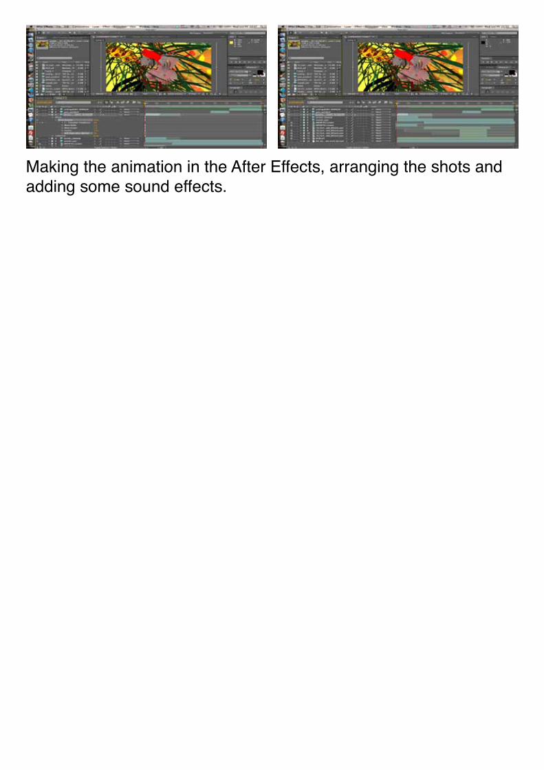
Making the animation in the After Effects, arranging the shots and adding some sound effects.