3d printed bionic nanodevices - university of utah
TRANSCRIPT

N
R
3
YM
a
Mb
c
d
RA
h1
ano Today (2016) 11, 330—350
Available online at www.sciencedirect.com
ScienceDirect
journa l homepage: www.e lsev ier .com/ locate /nanotoday
EVIEW
D printed bionic nanodevices
ong Lin Konga,∗, Maneesh K. Guptab, Blake N. Johnsonc,ichael C. McAlpined,∗∗
Koch Institute for Integrative Cancer Research, Massachusetts Institute of Technology, Cambridge,A 02139, USAAir Force Research Laboratories, Wright-Patterson Air Force Base, OH 45433, USADepartment of Industrial and Systems Engineering, Virginia Tech, Blacksburg, VA 24061, USADepartment of Mechanical Engineering, University of Minnesota, Minneapolis, MN 55455, USA
eceived 28 January 2016; accepted 6 April 2016vailable online 29 April 2016
KEYWORDS3D printing;Bionic devices;Nanomaterials;Nanodevices;Bioelectronics;Bio-nano hybrids
Summary The ability to three-dimensionally interweave biological and functional materi-als could enable the creation of bionic devices possessing unique and compelling geometries,properties, and functionalities. Indeed, interfacing high performance active devices with biol-ogy could impact a variety of fields, including regenerative bioelectronic medicines, smartprosthetics, medical robotics, and human—machine interfaces. Biology, from the molecularscale of DNA and proteins, to the macroscopic scale of tissues and organs, is three-dimensional,often soft and stretchable, and temperature sensitive. This renders most biological platformsincompatible with the fabrication and materials processing methods that have been developedand optimized for functional electronics, which are typically planar, rigid and brittle. A num-ber of strategies have been developed to overcome these dichotomies. One particularly novelapproach is the use of extrusion- based multi-material 3D printing, which is an additive man-ufacturing technology that offers a freeform fabrication strategy. This approach addresses thedichotomies presented above by (1) using 3D printing and imaging for customized, hierarchical,
and interwoven device architectures; (2) employing nanotechnology as an enabling route forintroducing high performance materials, with the potential for exhibiting properties not found inthe bulk; and (3) 3D printing a range of soft and nanoscale materials to enable the integrationof a diverse palette of high quality functional nanomaterials with biology. Further, 3D prin-ting is a multi-scale platform, allowing for the incorporation of functional nanoscale inks, theprinting of microscale features, and ultimately the creation of macroscale devices. This blending∗ Corresponding author. Tel.: +1 609 356 3699.∗∗ Corresponding author. Tel.: +1 609 542 0275.
E-mail addresses: [email protected] (Y.L. Kong), [email protected] (M.C. McAlpine).
ttp://dx.doi.org/10.1016/j.nantod.2016.04.007748-0132/© 2016 Elsevier Ltd. All rights reserved.

3D printed bionic nanodevices
of 3D printing, novel nanomateriabionic systems. In this review, weof nanomaterials with the versatinanomaterials and fabricate nove© 2016 Elsevier Ltd. All rights res
patemtf
wcibnmcdFmttYSa[nwa
podtauaspstfm
ad[om
Introduction
The synergistic integration of biological systems with elec-tronic materials and devices could enable the creation ofnovel bionic devices. Due to the increasing miniaturizationand proliferation of portable electronic devices, the fieldof bionics has transitioned from science fiction to an areaof increasing scientific interest, with particular relevanceto the fields of regenerative medicine, smart prosthet-ics, medical robotics and human—machine interfaces [1—4].Most research in the field of bionics to date has focusedon developing robots which behave increasingly more likehumans. Similarly, an equally compelling challenge is inte-grating electronic and robotic components in a seamlessmanner with the human body. For example, bioelectronicmedicines and devices could potentially be utilized torestore or even augment the complex functionalities of nat-urally evolved biological systems. At the fundamental level,there are inherent material compatibility challenges asso-ciated with integrating functional electronic materials withbiology.
The term ‘‘bionics’’ is defined by Dictionary.com as,‘‘utilizing electronic devices and mechanical parts toassist humans in performing difficult, dangerous, or intri-cate tasks, by supplementing or duplicating parts of thebody [5].’’ Broadly speaking, ‘‘bionics’’ encompasses thefunctionalities of classes of systems that are formed bymerging biological systems, which could be single cellular ormulti-cellular systems [2,6—8], with engineered mechanicaland/or electronic systems [2]. Our ability to develop tools,which overcome the limitations of human biology, has playeda key role in survival and evolution [9]. Utilizing devices forregenerative medicine and as prosthetics can be traced backmillennia [1]. Indeed, a very primitive bionic device from thefirst century AD involved the use of wrought iron for dentalreplacements [10]. Subsequently, bionic devices such as ironprosthetic hands (1504), contact lenses (1888), and artificialhip replacements (1905) have been used to restore or aug-ment human function [1]. Over the past several decades, thedevelopment of active microelectronic devices has enabledthe incorporation of sensing modalities [11,12], optoelec-tronics [13,14], actuators [15] and computational devices[16] into previously passive mechanical constructs. This hasenabled an extension of the role of bionic devices towardmimicking or even augmenting the complex functionalitiesof biological organs. These powerful developments havebeen leveraged to fabricate active bionic devices such as
the cochlear implant [17,18] to restore hearing (Fig. 1A),pacemakers and heart replacements [1] to sustain bloodflow (Fig. 1B), locally powered prosthetic devices [19] toprovide mobility to amputees (Fig. 1C), retinal implants toatEt
331
l properties, and ‘living’ platforms may enable next-generationhighlight this synergistic integration of the unique properties
lity of extrusion-based 3D printing technologies to interweavel bionic devices.erved.
rovide partial restoration of vision loss due to diseases suchs retinitis pigmentosa [20,21] (Fig. 1D), dura mater forhe spinal cord [22] (Fig. 1E), and digital skin sensors andlectronic skins [12,23—25] (Fig. 1F). Indeed, the ability toerge a diverse palette of materials classes could enable
he generation of functional devices that mimic the complexunctionalities of grown biological organs [15].
An optimized bionic device should be seamlessly mergedith the human body in order to restore or augment humanapabilities without causing side effects such as discomfort,nfection [26] or rejection due to foreign body responsesy the host [27—29]. While the continual discovery ofew materials and novel properties will eventually lead toore optimized devices, ideality has been punctuated by
hallenges in integrating high performance materials andevices with biology. Three key challenges can be identified.irst, the mechanical properties of high quality electronicaterials are typically disparate from biology. For example,
he typical Young’s modulus of inorganic electronics is onhe order of 1—100 GPa (Si ∼ 170 GPa) [30]. By contrast, theoung’s modulus of skin is on the order of 0.1—1 MPa [31].imilarly, inorganic electronic materials typically fracturet strains (ca. 1%) [32] of up to 30× lower than human skin33]. These significant differences in mechanical propertiesot only lead to obstacles in the integration of bionic devicesith the body, but can cause discomfort, agitation, rejectionnd injuries.
Second, the processing conditions inherent to higherformance electronics are often incompatible with biol-gy. Microelectronics are typically fabricated via ‘‘topown’’ approaches which can involve harsh chemical andemperature processing conditions. In contrast, organsnd tissues have been grown from the ‘‘bottom up’’nder finely tuned physiological conditions [35]. Thirdnd finally, electronic wafers are two-dimensional planartructures, whereas biology possesses intricately com-lex three-dimensional geometries from the molecularcale to the macroscale. These incompatibilities collec-ively present significant barriers in grafting independentlyabricated bionic devices onto biology in a seamlessanner.A variety of novel strategies have been developed to
ddress these issues, such as integration via intelligentevice design [11,32,36,37], transfer printing processes13,38—41] and/or assembly of prefabricated devices [42]nto three-dimensional constructs to accommodate the geo-etrical and material incompatibility. This review highlightsrelatively new concept in achieving a synergistic integra-
ion of bionic devices with biology: by using 3D printing.xtrusion-based 3D printing technologies may overcome thehree specific challenges mentioned above. First, the use of

332 Y.L. Kong et al.
Figure 1 Bionic technologies for restorative medicine. (A) Cochlear implant [18]. (B) AbioCor self-contained replacement heart[1]. (C) Powered ankle-foot prosthetic controlled by a neuromuscular model [19]. (D) Epiretinal, subretinal, and suprachoroidalimplants [21]. (E) Electronic dura mater, ‘‘e-dura,’’ tailored for the spinal cord [22]. (F) A skin-inspired digital mechanoreceptor,where the image shows a model hand with DiTact sensors on the fingertips connected with stretchable interconnects [12].Reprinted with permission from Refs. [18,1,19,21,22,12], respectively. Copyright 2009 Nature Publishing Group, 2002 AmericanAssociation for the Advancement of Science, 2010 IEEE, 2013 American Association for the Advancement of Science, 2015 AmericanA
ncacpttvtowii
fomsatts
3
3taDcbu3fttc[
bt
ssociation for the Advancement of Science.
anoscale materials as inks in the 3D printing process and theo-printing of soft materials and functional nanoscale inksllows for a route which minimizes mechanical discrepan-ies. Second, while the materials may be synthesized and/orrocessed under harsh, high temperature conditions in ordero create high quality functional nanomaterials, the prin-ing process is typically performed under ambient conditionsia a bottom-up assembly process. Finally, the 3D prin-ing process naturally allows for the hierarchical assemblyf functional materials in three dimensions, commensurateith biology. An additional benefit of 3D printing is the abil-
ty to achieve a multi-scale manufacturing approach builtnto the process.
This review article will first describe this multi-scaleabrication approach and highlight the unique propertiesf nanoscale conductive, semiconducting and plasmonicaterials. Next, we will describe the challenges and
trategies associated with the microscale printing and
ssembly of these nanoscale functional materials. We willhen review progress to date in the use of 3D printingo create unique bionic architectures at various lengthcales.[ppE
D printing for multiscale manufacturing
D printing is an additive manufacturing process usedo build three-dimensional structures from computer-ided design (CAD) models in a layer-by-layer fashion.eveloped since the 1980s [43], 3D printing has theapability to create unique architectures that cannote made with conventional molding or subtractive man-facturing techniques. Further, the co-development ofD imaging technologies, such as 3D scanning, allowsor the acquisition of three-dimensional topological datahat precisely reproduces a three-dimensional object andhe incorporation of three-dimensional templates for theonformal printing of devices on non-planar substrates44—46].
3D printing is commonly associated with either light-ased or ink-based printing techniques [47]. Light-basedechniques are founded on processes such as UV curing
43,48,49] and two-photon polymerization [50]. Ink-basedrinting can be achieved via extrusion printing, inkjetrinting [51], and electro-hydrodynamic printing [52].xtrusion-based 3D printing is a particularly interesting
333
Figure 2 Multiscale, multi-material 3D printing. (A) Func-tional nanomaterials can be dispersed in solvents to formsolution-processable inks. (B) The inks are then 3D printed atmicroscale via extrusion from a suitable nozzle. (C) The three-dimensional co-printing of various classes of materials enablest
pecs
ntpo
3D printed bionic nanodevices
subset of additive manufacturing in which the materials areextruded through a nozzle [47,53—57]. Such a platform ishighly versatile, affordable [58] and can be readily expandedto incorporate multiple materials [59—61]. Moreover, in con-trast to other printing methods, such as inkjet printing(where the typical viscosity is limited to ca. 2—102 mPa s[51]), extrusion-based 3D printing is capable of incorporat-ing a wide range of materials with viscosities up to 106 mPa sand with disparate properties [47,61]. This versatility hasenabled the accommodation of different classes of materialsand products encompassing a wide range of length-scales:including nanomaterials [61,62], fibers [63], cells [64,65],tissues [66], organs [55,67], ceramics [68,69], metals [70]and polymers such as elastomers [59,60,71], gels [34,72,73],and biomaterials [55,74,201].
Nanomaterials represent novel building blocks in thetoolset of 3D printed functionalities. These are materialswhich are confined such that at least one of their lengthscales is in the range of ca. 1—100 nm. As conceived byRichard Feynman in 1959 [75], assembling materials fromthe bottom-up has become an important assembly strat-egy for nanoscale materials [76], enabled by the abilityto make such materials using scalable synthetic methods[77—81]. Functional nanomaterials can be dispersed intosolvents to form solution-processable inks, as shown inFig. 2A, which can be extruded from nozzles to createmicroscale features (Fig. 2B) commensurate with typicalbiological length scales. Finally, the co-printing of nano-materials with soft, structural, and/or biological constructsenables the freeform fabrication of three-dimensional,macroscale, multi-material functional devices as illustratedin Fig. 2C. Extrusion-based 3D printing thus provides apromising platform for the interweaving of different mate-rials and functionalities.
Functional nanoscale inks
Nanoscale inks are attractive for a number of reasons.Nanomaterials approach length scales such that externalforces are negligible in comparison with van der Waalsinteractions [82]. Hence, nanomaterials can be assembled[83] or coated on arbitrarily-shaped three dimensional sub-strates with high adhesion. For example, a monolayer ofgraphene has been shown to exhibit an adhesion energyof 0.45 J m−2 on a silicon oxide substrate [84]. Approa-ching the nanoscale, the surface-to-volume ratio increasesas the particle size decreases [85,86]. This geometric effecthas important consequences. For example, the decreasein particle size reduces the material melting temperature[87,88]. An example of this relationship between size andthe melting point [89] is low melting point silver nanoparti-cles [90] that can be sintered to form a conductive path atlower temperatures than the bulk material. Nanomaterialproperties are also highly tunable. In 1847, Michael Fara-day discovered that the optical properties of gold colloidsdeviated from their bulk counterparts [91], introducing theprospect of tuning functional properties by tailoring the
size of materials. The band gap of semiconducting nano-materials is size-dependent below the Bohr exciton radius[85,86,92]. For example, the fluorescence of CdSe—CdScore—shell nanoparticles shifts from red to blue when thei[tb
he creation of macroscale functional devices.
article size decreases from 6 nm to 1.7 nm [93]. Theseffects offer a means of controlling the electronic and opti-al properties of nanomaterials by tuning their size duringynthesis.
The ability to synthesize monodisperse nanowires andanoparticles permits the development of printable inkshat capture the unique properties of nanomaterials in arintable format, by suspending the nanoparticles in aque-us or organic solvents [77—81]. Stabilization in the solvents typically achieved via the addition of polymeric materials
94] and surfactants, or via electrostatic interactions [95]o prevent aggregation and precipitation. The extrusion-ased 3D printing method supports a wide range of fluid
3
ptcamctpfmaansecscccphc
oe[dcpiiawssaslf[
eirTsttt[snutsisvtt
M
Tcpo[awfsIouwfiptdta‘ope
mdf[cfiieoetrfiiigmgtMdtipbt
ahslp
34
roperties, and the printability can be tailored by modifyinghe surface tension and viscosity of the inks. Three commonlasses of printable inks include conducting, semiconductingnd plasmonic nanomaterials. Printable conducting nano-aterials [96] can be synthesized with metallic [97] and
arbon-based nanoparticles. Further, the ability to printhin conductive layers also enables the printing of trans-arent conductors [98,99] that can function as electrodesor optoelectronic devices [100,101]. Highly conductiveetals such as silver [90,102] and gold [103,104] are suit-
ble printable inks which, unlike other metals such asluminum [105], are less susceptible to oxidation. Alter-atively, carbon nanomaterial-based conducting inks [98]uch as graphene and carbon nanotubes have been activelyxplored. Graphene [106—108], an atomically thick layer ofarbon atoms, is attractive due its exceptionally high intrin-ic mobility [109,110]. A mobility as high as 5000 cm2 V−1 s−1
an be achieved in printed graphene films [111]. Hybridomposites can also be formed by mixing both metal- andarbon-based inks. For instance, a highly conductive com-osite (5.7 × 10⁵ �−1 m−1) that can be strained up to 140%as been demonstrated with a silver flake/carbon nanotubeomposite [112].
Printable semiconducting nanoscale inks provide a meansf introducing active electronic functionality and tuninglectrical and optical properties. Quantum dots (QDs)92] are zero-dimensional nanoscale crystals of semicon-ucting materials, in which quantum confinement oftenauses a deviation of properties from the bulk. For exam-le, the emission wavelength of cadmium selenide QDss tunable by changing the particle size [113]. QDs typ-cally consist of an inorganic semiconductor core and
coating of ligands to confer solubility in solvents. Aider-bandgap inorganic material can also be coated as a
hell to passivate the surface, thereby improving intrin-ic properties such as photoluminescence quantum yieldnd photo-stability [78]. Further, the ability to synthe-ize highly monodisperse QDs with narrow size distributionseads to narrow emission spectra [114] that is usefulor display devices with high color purity and saturation115].
Plasmonic nanomaterials are metal nanoparticles thatxhibit a localized surface plasmon resonance (LSPR), whichs a collective oscillation of conduction band electrons inesponse to the electric field component of incident light.he unique optical properties such as large absorption andcattering cross-section, high sensitivity to the local dielec-ric environment, and enhanced electromagnetic field athe surface render plasmonic nanomaterials a highly attrac-ive class of materials for a broad range of applications116]. The LSPR wavelength is dependent on the compo-ition, size, shape, coupling, and ambient dielectric of theanoparticles. In biomedicine, plasmonic nanoparticles aresed in applications for diagnostics and therapeutics. Whileremendous progress has been made in the synthesis ofize- and shape-controlled plasmonic nanostructures, theirntegration with other materials and application in solid-tate devices is primarily either via direct fabrication (using
arious lithographic techniques) or immobilization on solidwo-dimensional (2D) substrates such as silicon, glass, plas-ic, or paper.mta
Y.L. Kong et al.
icroscale 3D printing of inks
he ability to pattern solution-processed nanomaterial inksan lead to the creation of devices [117—119], where theroperties of the film such as its thickness and morphol-gy dictate the quality of the resulting device performance120]. In microfabrication-based methods, this is typicallyccomplished via processes such as spin-coating [121], inhich the liquid ink is spread uniformly via centrifugal
orces. However, such processes require a rigid and flat sub-trate, as well as the use of photolithography for patterning.n addition, the spin coating of quantum dots expels 94—97%f the starting solution, which increases the material cost byp to 20-fold [122]. Yet, a colloidal ink printed onto a surfaceithout spin-coating typically does not lead to a uniformlm. When a droplet is left to evaporate on a substrate, theinning of the contact line results in a non-uniform evapora-ion rate at the surface of the printed droplet. The enhancedrying rate at the edge of the droplet due to the curva-ure difference drives the assembly of suspended particlest the edge of the evaporating solvent, resulting in so-called‘coffee rings’’ [123,124], as shown in Fig. 3A. The formationf multiple rings can also be observed, due to the repeatedinning and unpinning of the contact lines as the printed inkvaporates [125].
To overcome this non-homogeneous deposition, theicroscale printing of nanomaterials can be achieved viairected or self-assembly based methods [83]. Externalorces, such as electrical forces [126], or magnetic forces127] can be applied to drive the assembly of the parti-les. The assembly can also be achieved without an externaleld. For instance, a Marangoni effect [128—130] can be
ntroduced to drive the particle accumulation away from thedge of the droplet. This can be achieved via the additionf a co-solvent, which introduces a surface tension gradi-nt that generates the Marangoni flow. As shown in Fig. 3B,he introduction of 20% of dichlorobenzene to a QD inkeduces the root-mean square roughness of the resulting QDlm 9-fold in comparison to a single-solvent ink [61]. Sim-
larly, a surface tension gradient can be generated via thentroduction of a vapor environment. For instance, the filmenerated from an aqueous suspension has a higher unifor-ity in ethanol vapor due to the strong recirculating flow
enerated by the surface tension gradient [131]. Alterna-ively, the addition of a small ionic surfactant introduces aarangoni eddy of particles, which improves uniformity ofeposition [132]. The addition of hydrosoluble polymer addi-ives can also mitigate pinning of the contact line via anncrease in viscosity and the Marangoni effect, which sup-resses the coffee ring effect [133]. Coffee rings can alsoe reduced by introducing temperature control [134], sinceemperature affects the edge evaporation rate.
Interestingly, modification of the particle shape can alsoffect the subsequent deposition. For instance, Yunker et al.ave shown that anisotropic shaped particles, such as ellip-oids, introduce strong inter-particle interactions to formoosely packed structures that prevent the accumulation ofarticles at the edges of the droplet [135]. Impressively,
onolayer assembly of nanoparticles has been achieved byailoring the evaporation kinetics and particle interactionst the liquid-air interface [136], as described in Fig. 3C.

3D printed bionic nanodevices 335
Figure 3 Microscale patterning of nanoscale inks on a surface. (A) Challenges inherent to assembling particles via convectiveself-assembly methods. Top left figure shows formation of so-called ‘‘coffee-rings,’’ typically observed when a colloidal suspensiondroplet dries on a surface. The photograph is of a deposit left by 100 nm microspheres with a volume fraction of 1%. Top rightfigure shows non-uniformity in the region of the ring, where the gray scale indicates the density of particles with the white colorindicating the highest density. Scale bar is 500 �m [124]. Bottom figure show the superimposed exposures that illustrate the motionof the particles toward the edge of the droplet during the drying process [123]. (B) Non-uniformity can be reduced by introducing aco-solvent. Top figure shows the deposition of quantum dots from pure toluene, while bottom figure shows an improvement in themorphology via the introduction of 20% dichlorobenzene [61]. Scale bar is 1 mm. (C) Evaporation kinetics and particle interactionswith the liquid-air interface can be tailored to achieve monolayer assembly of nanoparticles. Micrograph shows the monolayerproduced by a solution of dodecanethiol-ligated 6 nm gold nanocrystals. Inset shows the fast Fourier transform (FFT) of the image[136]. (D) Arrays of quantum dots are generated via stick-slip motion of the contact line. The features are controlled by the velocityprofile of the translation stage. Bottom right figure shows the fluorescent microscopy image of grid patterns of the quantum dots.Scale bar is 200 �m [142].
specPub
hwTac
up
Reprinted with permission from Refs. [124,123,61,136,142], rePublishing Group, 2014 American Chemical Society, 2006 Nature
For example, assembly of a large nanoparticle monolayerfilm (3 mm × 4 mm) has been generated on a Si3N4 substratewithout the application of external fields. The ligands ofthe nanoparticles also play a critical role in this assemblyapproach, and excess ligand has been found to play a keyrole in generating the thin film using this method [136]. Thecoffee-ring effect can be leveraged to create high resolu-tion patterns and features which are otherwise challenging
to create via direct-writing with a 3D printer. For instance,a transparent conductive film can be formed from silvernanoparticle rings generated with the coffee ring effect. Anetwork of silver nanoparticle rings (10 �m width, 300 nmsohm
tively. Copyright 2000 American Physical Society, 1997 Naturelishing Group, 2010 John Wiley & Sons.
eight, 150 �m diameter) can generate a conductive filmith a resistivity of 4 × 10⁻⁷ � m and a transparency of 95%.his method is not limited to silver nanoparticles, and haslso been demonstrated with carbon-based particles such asarbon nanotubes [137].
Similarly, ‘‘stick-slip’’ motion can be used to create aniform array of nanoparticles. Unlike the irregular ringattern resulting from a droplet left evaporating on a
urface, ‘‘bands’’ can be assembled by confining the evap-ration rate of the inks. The exploitation of such effectsave been demonstrated to yield highly regular arrays oficrometer size band structures in both planar [138,139]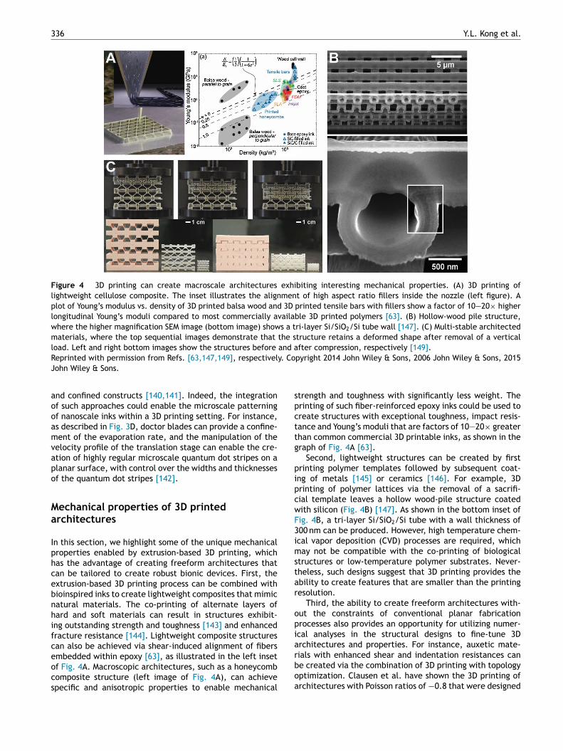
336 Y.L. Kong et al.
Figure 4 3D printing can create macroscale architectures exhibiting interesting mechanical properties. (A) 3D printing oflightweight cellulose composite. The inset illustrates the alignment of high aspect ratio fillers inside the nozzle (left figure). Aplot of Young’s modulus vs. density of 3D printed balsa wood and 3D printed tensile bars with fillers show a factor of 10—20× higherlongitudinal Young’s moduli compared to most commercially available 3D printed polymers [63]. (B) Hollow-wood pile structure,where the higher magnification SEM image (bottom image) shows a tri-layer Si/SiO2/Si tube wall [147]. (C) Multi-stable architectedmaterials, where the top sequential images demonstrate that the structure retains a deformed shape after removal of a verticalload. Left and right bottom images show the structures before and after compression, respectively [149].R y. CoJ
aooamvapo
Ma
Iphcebnhifceocs
spcttg
pipcwF3imstar
opia
eprinted with permission from Refs. [63,147,149], respectivelohn Wiley & Sons.
nd confined constructs [140,141]. Indeed, the integrationf such approaches could enable the microscale patterningf nanoscale inks within a 3D printing setting. For instance,s described in Fig. 3D, doctor blades can provide a confine-ent of the evaporation rate, and the manipulation of the
elocity profile of the translation stage can enable the cre-tion of highly regular microscale quantum dot stripes on alanar surface, with control over the widths and thicknessesf the quantum dot stripes [142].
echanical properties of 3D printedrchitectures
n this section, we highlight some of the unique mechanicalroperties enabled by extrusion-based 3D printing, whichas the advantage of creating freeform architectures thatan be tailored to create robust bionic devices. First, thextrusion-based 3D printing process can be combined withioinspired inks to create lightweight composites that mimicatural materials. The co-printing of alternate layers ofard and soft materials can result in structures exhibit-ng outstanding strength and toughness [143] and enhancedracture resistance [144]. Lightweight composite structuresan also be achieved via shear-induced alignment of fibers
mbedded within epoxy [63], as illustrated in the left insetf Fig. 4A. Macroscopic architectures, such as a honeycombomposite structure (left image of Fig. 4A), can achievepecific and anisotropic properties to enable mechanicalrboa
pyright 2014 John Wiley & Sons, 2006 John Wiley & Sons, 2015
trength and toughness with significantly less weight. Therinting of such fiber-reinforced epoxy inks could be used toreate structures with exceptional toughness, impact resis-ance and Young’s moduli that are factors of 10—20× greaterhan common commercial 3D printable inks, as shown in theraph of Fig. 4A [63].
Second, lightweight structures can be created by firstrinting polymer templates followed by subsequent coat-ng of metals [145] or ceramics [146]. For example, 3Drinting of polymer lattices via the removal of a sacrifi-ial template leaves a hollow wood-pile structure coatedith silicon (Fig. 4B) [147]. As shown in the bottom inset ofig. 4B, a tri-layer Si/SiO2/Si tube with a wall thickness of00 nm can be produced. However, high temperature chem-cal vapor deposition (CVD) processes are required, whichay not be compatible with the co-printing of biological
tructures or low-temperature polymer substrates. Never-heless, such designs suggest that 3D printing provides thebility to create features that are smaller than the printingesolution.
Third, the ability to create freeform architectures with-ut the constraints of conventional planar fabricationrocesses also provides an opportunity for utilizing numer-cal analyses in the structural designs to fine-tune 3Drchitectures and properties. For instance, auxetic mate-
ials with enhanced shear and indentation resistances cane created via the combination of 3D printing with topologyptimization. Clausen et al. have shown the 3D printing ofrchitectures with Poisson ratios of −0.8 that were designed
3D printed bionic nanodevices 337
Figure 5 Schematic of 3D static and 4D dynamic printingmethods to create chemical and biomolecular gradients. (A)Static methods allow for a preprogrammed gradient to be devel-oped, typically based on passive diffusion from payload depots.
Figure 6 (A) Schematic showing a 3D printing strategy tocreating stimuli-responsive capsules that can be selectivelyruptured to release payloads in response to optical stimuli.Incorporation of gold nanorods in the shells allows the capsulesto be ruptured by exposure to laser wavelengths determined bythe lengths of the incorporated nanorods. (B) Optical imagesof complex capsule arrays including a printed ‘tiger’ and a pHgradient array with different colors from an indicator dye. (C)Programmed rupture and release of HRP from capsules by selec-tive laser exposure [62].Ri
clmtmoabocp
(B) Dynamic methods allow for ‘‘on the fly’’ active reprogramm-ing of gradients, by including the fourth dimension of time.
via numerical optimization [148]. In another example, Shanet al. demonstrated 3D printed multi-stable structures withenhanced absorption of compression energies, as shownin Fig. 5C [149]. The printed beam elements are able torespond to external loading by reconfiguring, in a reversiblefashion, into other stable structures without mechanicalfailure. Such novel geometries could potentially enable thecreation of robust bionic devices with enhanced impactresistance and energy-absorbing capabilities to withstandwear and impact.
Finally, beyond serial printing using individual nozzles,a more seamless and parallel merging of multiple materi-als can be achieved by incorporating nozzle designs thatenable the co-printing of different materials to achieveunique multi-material architectures. In addition to increas-ing throughput [150], multi-nozzle microfluidic printheadsallow for the rapid co-printing of two different viscoelasticinks to create architectures with sharp transitions of differ-ent materials [60]. This multi-material integration has alsobeen demonstrated via an active mixing of viscoelastic inksto achieve programmable control over local compositions[59].
3D printing of spatiotemporal biomoleculargradients
The ability to mimic the dynamic microenvironment sur-rounding cells in natural tissues is critical to engineering thebiotic/abiotic interfaces found in bionic systems [151—153].
Indeed, cell fate is influenced by numerous molecular fac-tors and interactions that require meticulous control forthe regeneration of functional tissue [154,155]. In order toachieve such control, engineered matrices should ideally begrt[
eprinted with permission from Ref. [62]. Copyright 2015 Amer-can Chemical Society.
apable of generating multiplexed spatiotemporal molecu-ar gradients. Extensive research efforts to engineer suchatrices have resulted in a number of promising methods
o generate and control molecular gradients (Fig. 5). Theseethods can generally be categorized as static 3D meth-
ds (Fig. 6A) where the gradient is fixed once programmed,nd dynamic 4D methods (Fig. 6B) where the gradients cane reprogrammed by the user. The focus of this review isn strategies to generate biomolecular gradients that areompatible with 3D printed systems, and as such a com-lete description of tissue culture compatible methods toenerate biomolecular gradients is beyond the scope of this
eview. The reader is referred to several literature sourceshat provide excellent in-depth discussions of such methods151,155,156].
3
3
TsiatowoobstoimiaAtb
ibp[taeodcgomwdatrof
higmroltocobelt
lg
rteiscrodpepfttmpei
haNpptwtbivitctst
bsatbmgtsmnott
4
Ticontrol over its temporal evolution. The concept of stimuli-
38
D static printing of gradients
he simplest method for creating a hydrogel scaffold with atatic biomolecular gradient is through direct spatial local-zation of biological factors within the hydrogel. In thispproach, once the spatial gradient has been generated,he temporal persistence of the gradient is based solelyn the diffusivity of the biomolecule within the hydrogel,hich is generally a function of the size and chemistryf the biomolecule, crosslinking density, water fractionf the hydrogel, and molecular interactions between theiomolecule and the hydrogel polymer. Scaffolds withuch gradients can be made via solid freeform fabricationhrough sequential deposition of hydrogels containing vari-us concentrations of differing biomolecules. This strategys compatible with both extrusion and light-based printingethods [157]. These approaches are suitable for creat-
ng relatively simple gradients using a few biomolecules,nd gradients of soluble factors typically persist for days.pplications where a gradient is desired for longer dura-ions (weeks to months) require strategies to immobilize theiomolecule on the hydrogel polymer.
An alternative strategy to creating hydrogel gradientss to apply the gradient after the hydrogel scaffold haseen formed. A common approach to doing this is inkjetrinting of biomolecule solutions onto a hydrogel substrate158—162]. As the solution droplet impacts the surface ofhe hydrogel, it is quickly absorbed and the biomoleculesre localized to the 2D footprint of the droplet. Gradi-nt arrays can be created by dispensing varying numbersf droplets over the same area. The precise control overroplet volumes in inkjet printing allows researchers toreate gradients with precise concentrations and varyingradient profiles. Nuzzo et al. have developed a variantf this method [163]. By using soft contact printing of aicrofluidic network with a permeable membrane, theyere able to demonstrate transfer printing of complex gra-ients into the hydrogel substrate. Although these methodsre most commonly utilized with flat hydrogel substrates,hey can easily be integrated with methods for freeform fab-ication of hydrogel scaffolds by inkjet or transfer printingf gradients at select hydrogel layers during the freeformabrication process.
The simplicity of directly incorporating gradients in theydrogel has made this approach widely used, particularlyn fundamental studies where the effect of a particularradient on cell behavior is being studied. However, aajor consideration is the lack of control over the tempo-
al evolution of the gradient and the cumbersome naturef incorporating multiplexed gradients. Micro/nanoparticlesoaded with biomolecules represent a versatile approacho delivering multiplexed gradients with additional controlver the release kinetics [164,165]. While such particlesan be made via numerous methods and from a wide rangef materials, they are most commonly formulated fromiodegradable polymers using double emulsification or coac-rvation methods [166]. The particles can be efficientlyoaded with a variety of biomolecular payloads, while main-aining their activities [167].
Synthesizing particles loaded with different factors andocalizing them within a hydrogel matrix can lead to theeneration of multiplexed spatial gradients. The payload
rfc
Y.L. Kong et al.
elease kinetics can be adjusted by controlling the par-icle properties (e.g., diameter, shell thickness, porosity,tc.). However, spatiotemporal control over the gradientss typically coarse, as most scalable methods to synthe-ize particles result in highly polydisperse populations. Fineontrol over release dose is often required, and recentesearch efforts have focused on achieving robust controlver release kinetics. To this point, numerous groups haveeveloped microfluidic methods to synthesize monodispersearticles with a high degree of control over particle prop-rties [168,169]. While it is possible for such monodispersearticles to first be synthesized and collected, and then to beormulated into an ink for 3D printing, a more natural solu-ion is for direct incorporation of the microfluidic devices inhe printing nozzle. Currently, research efforts to developicrofluidic print nozzles have demonstrated single nozzlerinting of multiple materials with varying mechanical prop-rties, with the added ability to create discrete or gradednterfaces between the materials [60].
We have developed an alternative strategy to 3D printighly monodisperse capsule arrays (Fig. 7A) [62]. First,queous cores are printed onto a hydrophobic substrate.ext, the core is encapsulated by dispensing a biocompatibleolymeric solution which rapidly evaporates, leaving a solidolymer shell. The versatility of this approach is the abilityo accurately dispense multiplexed arrays over large areasith precise control over the core composition and the shell
hickness. Fig. 6B shows a ‘tiger’ consisting of 4000 red andlue cores, with a spacing of 400 �m. Adjacent is an opticalmage of a pH gradient array generated by printing varyingolumes of an acidic and basic ink. The color of each drops a result of the pH indicator m-cresol purple. The shellhickness of the capsules was varied by adjusting the con-entration of the polymer in the dispensed shell solution. Inhis manner, we were able to realize control over the pas-ive release kinetics of horseradish peroxidase (HRP) fromhe capsule core.
The passive 3D methods described here to generateiomolecular gradients could represent powerful tools fortudying the impact of a surrounding microenvironment onwide range of cellular responses. The major advantage of
hese methods is their broad applicability to a wide range ofiomolecules and hydrogel systems. For example, chemicalodification of the biomolecules and hydrogel polymers is
enerally unnecessary. The limitation, however, is that theemporal evolution of the gradient is ultimately controlledimply by diffusion of the biomolecules through the hydrogelatrix or capsule shell. As such, there are limited opportu-
ities to tailor the temporal response, especially in the casef multiplexed gradients. A more compelling alternative iso introduce vehicles for achieving precision control overime as well as space.
D dynamic printing of gradients
he incorporation of a selective, stimuli-responsive elementn a biomolecular gradient can provide an additional level of
esponsive controlled release has been extensively exploredor applications in drug delivery. Capsules, nanoparti-les, and hydrogels have been developed that release a

3D printed bionic nanodevices
Figure 7 3D printing strategies to create gradients inmacroscale structures. (A) An emulsion printing strategy to cre-ate stimuli-responsive multiplexed arrays of capsules within 3Dhydrogel matrices (cylinder outer diameter is 8 mm; cube edgelength is 10 mm) [62]. (B) Direct printing of vascular networksin granular media. Jamming of the media allows the printednetwork to be stabilized as it is printed [177]. (C) A carbohy-drate glass is printed as a sacrificial scaffold for the vascularnetwork. Once the gel matrix is cast, the scaffold is dissolvedleaving behind open channels (scale bars are 1 mm, left; 2 mm,right) [179]. (D) In this example, the authors use a fugitive inkto create microfluidic channels in a hydrogel. After the channelsare formed, the ink is removed by decreasing the temperatureto fluidize the fugitive ink [178].Reprinted with permission from Refs. [62,177,179,178], respec-tively. Copyright 2015 American Chemical Society, 2015
bcrm
trlmtboaaatppeaml
sotnlrcscmmar
itgwbgawipcddarirec
3D hybrid systems with dynamic gradients
American Association for the Advancement of Science, 2012Nature Publishing Group, 2014 John Wiley & Sons.
chemical payload in response to a wide range of user-applied external stimuli such as light, heat and magneticfield, or internal biological stimuli such as pH, temperatureand biomolecular signaling [170—173]. The main advantage
of stimuli-responsiveness in drug delivery is the ability tospecifically deliver drugs to affected cells and tissues whileminimizing side effects due to interactions with healthy tis-sues and cells. In tissue engineering and the creation ofAi
339
ionic devices, the primary advantage of stimuli-responsiveontrolled release is the ability to reprogram gradients inesponse to changes in cell growth, differentiation, and/origration.Novel labile chemical linkers have been used to pat-
ern and release biomolecules from polymer backbones inesponse to external stimuli. Most commonly, a photolabileinker is used to tether the biomolecule to the hydrogel poly-er [174]. When exposed to a particular wavelength of light,
he linker is degraded and the biomolecule becomes solu-le. The gradient can be established by either the solubler insoluble fraction of the biomolecule depending on thectivity of the particular system. Spatial patterning can bechieved by shining light through a photomask, or by usingtwo-photon response where the linker is only degraded in
he highly focused region of a laser beam. While this methodrovides excellent spatiotemporal control, selective multi-lexed release requires engineering orthogonal linkers forach molecular factor to be released, which can becomemajor technical challenge. Additionally, the activities ofany biomolecules can be decreased due to the covalent
inking, and strategies to mitigate this can be challenging.We have demonstrated a novel, selectively photorespon-
ive system using our 3D printed capsule platform [62]. Inrder to make the capsules photoresponsive, we loadedhe shells with gold nanorods. The LSPR wavelength of theanorod is strongly dependent on its length. In response toight exposure at the LSPR wavelength, the nanorods areapidly heated, melting the polymeric shell, such that theapsule ruptures — quickly releasing the payload. Fig. 7Chows the release of horseradish peroxidase from 2D printedapsules that have been ruptured. In this system, selectiveultiplexed release can be easily achieved, as no covalentodification is required to encapsulate the biomolecules,
nd gold nanorods with varying LSPR wavelengths can beoutinely prepared in large quantities.
Microfluidic channels have been directly incorporatedn hydrogels, providing a means to flow biomolecule solu-ions through gels as another strategy for creating dynamicradients [175,176]. Gradients can be established in twoays. First, a gradient can be generated by the diffusion ofiomolecules out of the microfluidic channel into the hydro-el matrix. Second, the flow of multiple solutions throughdesigned gradient generator can create precise gradientsithin the channel. This allows for the flexibility of generat-
ng steady-state gradients that can be maintained over longeriods of time. Additionally, the concentrations of solutionsan be rapidly varied for precise control of the temporalelivery of biological factors. However, multiple indepen-ent networks are required for multiplexed gradients, andn extensive pumping and fluid-handling infrastructure isequired. This approach is thus more suitable for generat-ng vasculature by consistently supplying nutrients to andemoving waste from the tissue, rather than a means of gen-rating transient gradients of biomolecules that can controlell fate at a local level.
longstanding challenge in tissue engineering has been thencorporation of dynamic gradients within macroscale 3D

3
siSsnpotTosissciawcoawp
fhipamidh(addyt
toTwnaritgioesnFgwasua
4fad
3
3ataiocabifaiaIaausn(
slhwh[drdenhcvnddnaaFwp
3
Mn
40
caffolds. A significant hurdle to accomplishing this goals the inherent challenges of multi-material 3D printing.timuli-responsive capsules and microfluidic networks aretrategies for generating dynamic gradients that requireovel materials and processes in order for them to be com-atible with 3D printing. In order to 3D print complex arraysf stimuli responsive capsules, we have developed a newype of ink based on a water-in-oil emulsion [62,177—179].he emulsion inks were prepared via high-speed dispersionf aqueous biomolecule solutions into a non-polar polymerolution. The emulsion-based ink was then directly printednto a thin layer of an aqueous hydrogel. Once printed, theolvent rapidly evaporates, leaving behind a solidified cap-ule sealed within the hydrogel. Thus, the hydrogel andapsules could be readily printed in a layer-by-layer fash-on to create complex 3D hierarchical programmable capsulerrays. Since the 3D printing process is based on digital soft-are control, rationally designed advanced architecturesould be constructed. For instance, Fig. 7A (left) shows anptical photograph of a hollow hydrogel cylinder containinglternating layers of red and blue capsules in the cylinderall, and (right) two inverted pyramidal arrays of capsulesrinted within a solid hydrogel cube.
Several recent examples have demonstrated thereeform fabrication of microfluidic networks in macroscaleydrogel scaffolds [177—179] via the use of a sacrificialnk to define the channel lumen. The primary challenge inrinting 3D microfluidic networks is that the sacrificial inknd hydrogel scaffold cannot be printed in a layer-by-layeranner, as doing so would not allow for continuous channels
n the Z-direction of the scaffold. Bhattacharjee et al. haveemonstrated the use of a granular gel medium into whichighly complex continuous 3D channels could be printedFig. 7B) [177]. Particle jamming in the media allowed forsystem where the yield stress was high enough to preventisruptions in the printed network due to differences inensities of the gel media and vascular network. Yet, theield stress was sufficiently low to allow the print nozzle toravel through the media without leaving a void in its wake.
In contrast to the previous example, another approacho creating microfluidic networks first involves the printingf a sacrificial ink in the shape of the desired network.hen, the scaffold is deposited around the solidified net-ork. Finally, once the scaffold is solidified the sacrificialetwork is removed. Miller et al. demonstrated such anpproach utilizing a carbohydrate-based glass as the sac-ificial ink (Fig. 7C) [179]. The carbohydrate glass is printedn the molten state and allowed to cool and solidify. Oncehe gel scaffold is cast and solidified, the carbohydratelass is dissolved away in water. A key advantage of thiss the compatibility of the sacrificial ink with a wide rangef hydrogel polymers. In another similar example, Koleskyt al. utilized inverse temperature responsive gelation of aacrificial ink and hydrogel scaffold to create 3D microfluidicetworks (Fig. 7D) [178]. Both the sacrificial ink (Pluronic®
-127) and hydrogel scaffold (gelatin methacrylate) are fullyelled between 4 and 22 ◦C. The F-127 liquefies below 4 ◦C,hereas, the gelatin is liquid above 22 ◦C. Thus, to create
microfluidic network the F-127 is first printed into thehape of the channels above 4 ◦C. Next, above 22 ◦C the liq-id gelatin is poured around the F-127 network and cooled tollow it to solidify. Finally, the temperature is lowered below
bili
Y.L. Kong et al.
◦C to liquefy the F-127, leaving channels in the gelatin scaf-old. These examples show the wide diversity in materialsnd processes that can be utilized to generate systems withynamic and complex biomolecular gradients.
D printed anatomical design
D printed multi-scale biological systems have includedrtificial tissues, organs, biomedical implants, and bionicissues. To date, 3D printed biological systems have beenpproached from three primary design paradigms, whichnclude: (1) anatomical design, (2) mechanical (i.e. physicalr topological) design, and (3) biochemical design. Anatomi-al design involves the development of 3D printed materialsnd devices which match the inherent anatomical structuresy mimicking their 3D geometry. Some of the earliest effortsn anatomical 3D printed biological systems came in theorm of engineering studies for craniofacial bone regener-tion. In one such study, helical computed tomography (CT)mages acquired from a dry mandible were used to gener-te the resultant 3D models for the printed scaffolds [180].t was shown that the dimensional error of the 3D printednatomical part, here the mandibular anatomy, varied frompproximately 1—3% depending on the printing techniquesed. Recently, anatomical design of 3D printed biologicalystems has expanded to include: (1) heart tissues [181], (2)erve scaffolds [64], (3) vascularized bone grafts [182], and4) artificial skin [183].
Anatomical structures include external and internal tis-ues and organs which range from micrometer to centimeterength scales. For example, as shown in Fig. 8A, 3D printingas fabricated biomimetic tri-leaflet heart valve conduits,hich use human aortic valvular interstitial cell-ladenydrogels of methacrylated hyaluronic acid and gelatin181]. Another highlight of anatomical design was recentlyemonstrated in the form of 3D printed anatomical nerveegeneration pathways. As shown in Fig. 8B, 3D modelseveloped from structured light scanning of nerve tissuenabled the regeneration of complex bifurcating peripheralerves in rats [64]. In addition to 3D printed scaffolds foreart and nerve tissue, advances in 3D printed bone and vas-ulature engineering have shown the ability to incorporateasculature within anatomical bone grafts for potential con-ection of the tissue to the blood supply (Fig. 8C) [182]. Asiscussed above, not only are anatomical design principlesriving the manufacturing of multi-scale anatomical inter-al tissues and organs [55,64,67,178,181,184], but they arelso guiding the exploration of external tissues which inter-ct with the surrounding environment [183]. For example,ig. 8D shows that 3D printed artificial skins can be realizedhich contain micro-structured biomimetic surface topogra-hies that achieve innovative hydrodynamic flows [183].
D printed biomechanical design
echanical (or topological) design involves the mimicry ofative mechanical properties and cues, such as stress-strain
ehavior, topographical structures, and microstructures,n 3D printed scaffold architectures. Some of the ear-iest efforts to examine the influence of physical cuesn 3D printed biological systems included the design of
3D printed bionic nanodevices 341
Figure 8 3D printed anatomical design strategies. (A) 3D printed tri-leaflet heart valve [181]. (B) 3D printed anatomical nerveregeneration pathway [64]. (C) 3D printed vascularized bone architectures [182]. (D) 3D printed biomimetic artificial skin (greenscale bar is 200 �m) [183].
ively
3
BcuStpgasiodoacotbtbtrtgntsensory nerve pathways (Fig. 10A) [64]. As shown in Fig. 10B,
Reprinted with permission from Refs. [181,64,182,183] respectWiley & Sons.
porous scaffolds for bone engineering applications [185].For example, 3D printing was used to assemble hydroxy-apatite scaffolds for bone regeneration over a range ofmechanical properties, such as porosity and strength. It wasshown that the mechanical properties and biological conse-quences of 3D printed scaffolds for bone regeneration maybe tuned by controlling the wall and channel thicknesses of3D printed grid-based scaffolds. Recently, mechanical designof 3D printed biological systems has expanded to include: (1)2D topographical cues in biomimetic in vitro models [65],(2) 3D topographical cues in 3D tissue scaffolds [64], and (3)bio-inspired mechanical systems [186].
The geometry of physical cues has included channels,grooves, and filaments. As shown in Fig. 9A, we recentlydemonstrated that a biomimetic nervous system on a chiptechnology can be realized via the controlled guidanceof axons within 3D printed polycaprolactone microchan-nels [65]. Similarly, Fig. 9B shows that 3D printed physicalcues in the form of microgrooves in anatomical elastomericscaffolds for peripheral nerve regeneration resulted in thealigned growth of axonal networks and cytoskeletons ofSchwann cells [64]. The parallel and orthogonal assembly ofmaterial filaments has provided flexible mechanical designopportunities in terms of controlling scaffold strength andfate of interacting cellular components. Further, the abilityto control filament assembly in non-uniform geometric pat-terns other than layer-by-layer approaches also enables oneto mimic various biomechanical systems. For example, asshown in Fig. 9C, it was recently shown that radial and spi-
ral filament strengths control the loading response in naturalwebbed systems, here a spider’s web [186].se
. Copyright 2014 Elsevier, 2015 John Wiley & Sons, 2014 John
D printed biochemical design
iochemical design involves the mimicry of a native bio-hemical structure or profile, which may include eitherniform or non-uniform distributions of biochemical factors.ome of the earliest efforts included the patterning of pro-ein gradients on 2D substrates [158]. In this study, inkjetrinting was used to print ciliary neurotrophic factor (CNTF)radients and examine their effect on the multi-potencynd differentiation of neural stem cells (NSCs) [158]. It washown that NSCs cultured on a printed gradient of increas-ng levels of CNTF showed a linear increase in the numbersf cells expressing glial fibrillary associated protein (GFAP),emonstrating a functional 3D printed gradient of CNTFn a 2D substrate. As discussed, 3D printing also has thebility to apply anatomical [64,67,178,181] and mechani-al [64,65,186] design principles toward the manufacturingf novel biological systems. Thus, the multiscale nature ofhe approach which combines anatomical, mechanical, andiochemical design paradigms also allows for the integra-ion of biochemical gradient technologies within macroscaleiological architectures in order to realize novel platformechnologies and biomedical devices. In our study of nerveegeneration in bifurcating mixed nerve pathways, 3D prin-ing was used to incorporate multi-component biochemicalradients of nerve growth factor (NGF) and glial cell-derivedeurotrophic factor (GDNF) within a global scaffold archi-ecture, to support the regeneration of both motor and
caffolds containing path-specific multi-component gradi-nts led to regenerated tissue which possessed enhanced

342
Figure 9 Mechanical design methodologies in 3D printedbiological systems. (A) 3D printed microchannels control thegrowth of axonal networks in a 3D printed nervous system on achip [65]. (B) 3D printed microgrooves in elastomeric anatom-ical nerve guides control the alignment of the regeneratingaxonal network longitudinally toward the injury site. Scale baris 1 mm [64]. (C) 3D printed spider web displaying interactingradial and spiral elastomeric filaments [186].Reprinted with permission from Refs. [65,64,186], respectively.Copyright 2015 Centre National de la Recherche Scientifique(CNRS) and Royal Society of Chemistry, 2015 John Wiley & Sons,2015 Nature Publishing Group.
ftfa
3
MmttttmaowdA(apftonfcdastbuttc(ts
maasiah[tttfpuct[shT
Y.L. Kong et al.
unctional return relative to scaffolds which did not con-ain supplemented gradients, thus validating the potentialor functional 3D printed multi-component gradients withinscaffold architecture to improve regenerative outcomes.
D printed conducting ink electronics
odern prosthetics typically incorporate electronics toimic, restore, and/or augment the complex functionali-
ies of biological constructs [1,12,18,19,21,22]. The abilityo create advanced electronics with 3D printing could leado methods for directly printing both the mechanical pros-hetics and the incorporated electronics from the sameachine, replete with customization of both geometries
nd functionalities. This section focuses on the printingf conducting nanoscale inks such as metal nanoparticles,hich can act as interconnects, or can be made into passiveevices such as strain sensors and antennas. For instance,hn et al. described the synthesis of a highly concentrated>70 wt%) viscoelastic ink with silver nitrate, poly(acryliccid) and diethanolamine [90]. Compared to previouslyublished inkjet printed metal nanoparticle inks, this inkormulation has a key advantage in its ability to createhree-dimensional interconnect arches as shown in the insetf Fig. 11A. These features overcome the conventional pla-ar constraints of traditional printing methods, allowingor interconnects that can span and stretch across cir-uit elements in three dimensions [90]. Further, Ahn et al.emonstrated an impressive minimum feature size of 2 �ms shown in Fig. 11A. This enabled the creation of featuresuch as a transparent conductive grid [187]. Significantly,he resistivity (5.2 × 10⁻⁷ � m) approaches the resistivity ofulk silver (10−8 � m), and this value can be achieved bysing a relatively mild annealing process (250 ◦C) for a shortime (30 min). The formulation of the inks and the printing ofhe electrodes into wavy architectures enabled the printedonductors to withstand repeated stretching and bendingmaximum strain of 25%). Such attributes are important inhe creation of stretchable bionic devices such as skin sen-ors [12].
The ability of extrusion-based 3D printing to accom-odate diverse materials with a wide range of viscosities
llows for the incorporation of classes of electronic materi-ls that are incompatible with other patterning processes,uch as inkjet printing or dip-pen lithography [188]. Fornstance, eutectic gallium-indium alloy (EGaIn) [189] is
highly conductive (3.4 × 10⁴ S cm−1) liquid metal thatas recently been explored as a 3D printable conductor70,190]. Intriguingly, despite its liquid nature at roomemperature (melting point = 15.5 ◦C), mechanically stablehree-dimensional structures can be achieved. This is dueo a high surface tension (0.6 N m−1) thin oxide film that isormed on the surface of the liquid (Fig. 11B). Further, arinting resolution of 100 �m has been demonstrated, andnlike most sintered solid metal, the liquid allows for thereation of highly stretchable (up to 100% elongation) elec-rodes when encapsulated within an elastomeric polymer
190], enabling the creation of stretchable devices such astrain gauges. Given the work function of −4.2 eV, EGaInas also been shown to be a suitable printable cathode.his is particularly useful for low melting point polymeric
3D printed bionic nanodevices 343
Figure 10 Biochemical design strategies in 3D printed biological systems. (A) Path-specific 3D printed multi-component gradient inanatomical nerve regeneration pathways [64]. (B) Effect of the functional 3D printed path-specific regeneration on the regeneration
of cSoci
obttTcftc
tfp
of motor and sensory nerve pathways, and the functional returnReprinted with permission from Ref. [64]. Copyright 2015 Royal
3D printed constructs, as thermal sintering processes can beavoided [61].
The ability to pattern in three dimensions allows forthe creation of electronics with unique or unusual perform-ances in comparison with planar patterning techniques. Forinstance, the printing of silver nanoparticles on a three-dimensional construct allowed for the fabrication of anantenna with an order of magnitude improvement overmonopole antenna designs (Fig. 12C) [191]. Further, theco-printing of conductive traces with an elastomeric sub-strate [59,60] can result in the freeform fabrication ofthree dimensional structures containing electronic com-ponents. For instance, capacitive soft strain sensors can
be realized via the printing of core-shell fibers with sili-cone and conductive fluids [71]. As shown in Fig. 11D, theembedded 3D printing of conductive carbon grease withinan elastomeric polymer enabled the seamless fabricationntub
omplex regenerated peripheral nerve injuries [64].ety of Chemistry.
f complex arrays of strain sensors within a glove, that cane used to monitor the motion of a user’s hand. Indeed,hese demonstrations highlight the many distinct advan-ages of 3D printing in the fabrication of electronic devices.hese include the realization of devices customized toonform to the user’s morphology, and customization ofunctionality by incorporating different classes of materialso create functional components within soft and stretchableonstructs.
The bottom-up nature of 3D printed electronics — andhe exclusion of the harsh chemicals and temperaturesound in microfabrication processes — allows for the co-rinting of electronics with biological materials to yield
ovel constructs even including bionic organs [55,67]. Thishree-dimensional interweaving of electronics and biologysing a multi-material 3D printing process was demonstratedy our group. Specifically, the co-printing of a cell-laden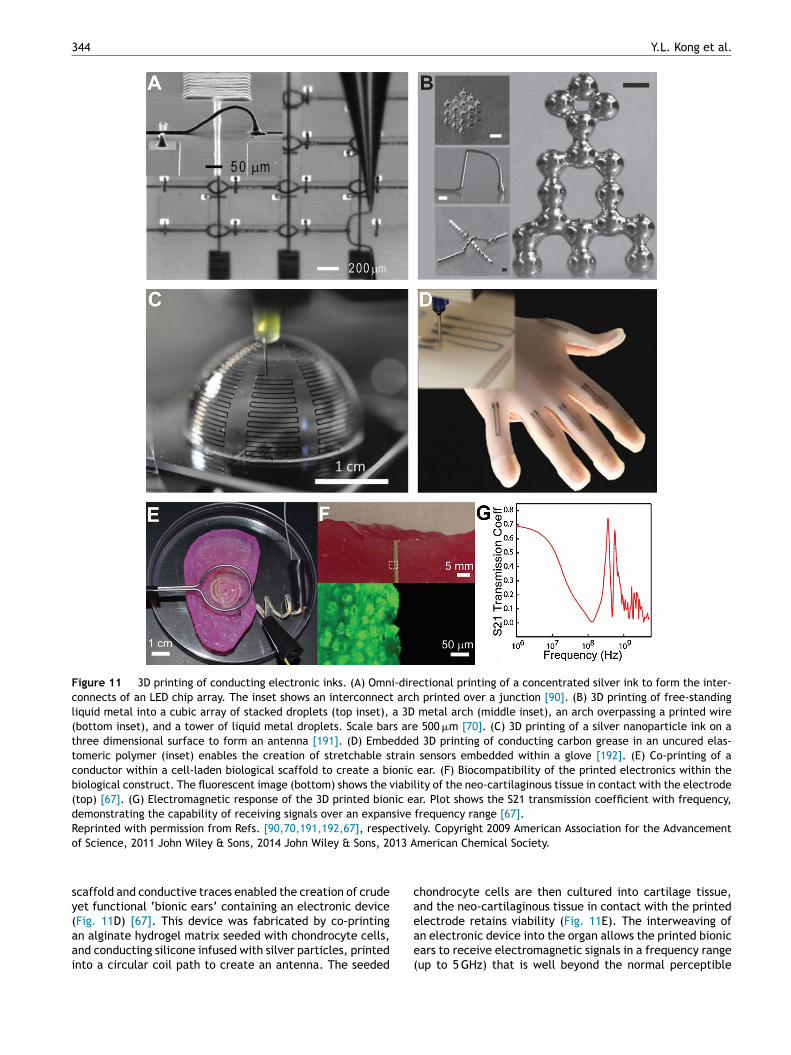
344 Y.L. Kong et al.
Figure 11 3D printing of conducting electronic inks. (A) Omni-directional printing of a concentrated silver ink to form the inter-connects of an LED chip array. The inset shows an interconnect arch printed over a junction [90]. (B) 3D printing of free-standingliquid metal into a cubic array of stacked droplets (top inset), a 3D metal arch (middle inset), an arch overpassing a printed wire(bottom inset), and a tower of liquid metal droplets. Scale bars are 500 �m [70]. (C) 3D printing of a silver nanoparticle ink on athree dimensional surface to form an antenna [191]. (D) Embedded 3D printing of conducting carbon grease in an uncured elas-tomeric polymer (inset) enables the creation of stretchable strain sensors embedded within a glove [192]. (E) Co-printing of aconductor within a cell-laden biological scaffold to create a bionic ear. (F) Biocompatibility of the printed electronics within thebiological construct. The fluorescent image (bottom) shows the viability of the neo-cartilaginous tissue in contact with the electrode(top) [67]. (G) Electromagnetic response of the 3D printed bionic ear. Plot shows the S21 transmission coefficient with frequency,demonstrating the capability of receiving signals over an expansive frequency range [67].Reprinted with permission from Refs. [90,70,191,192,67], respectively. Copyright 2009 American Association for the Advancemento 13 A
sy(aai
ca
f Science, 2011 John Wiley & Sons, 2014 John Wiley & Sons, 20
caffold and conductive traces enabled the creation of crudeet functional ‘bionic ears’ containing an electronic device
Fig. 11D) [67]. This device was fabricated by co-printingn alginate hydrogel matrix seeded with chondrocyte cells,nd conducting silicone infused with silver particles, printednto a circular coil path to create an antenna. The seededeae(
merican Chemical Society.
hondrocyte cells are then cultured into cartilage tissue,nd the neo-cartilaginous tissue in contact with the printed
lectrode retains viability (Fig. 11E). The interweaving ofn electronic device into the organ allows the printed bionicars to receive electromagnetic signals in a frequency rangeup to 5 GHz) that is well beyond the normal perceptible
3D printed bionic nanodevices 345
Figure 12 3D printing of active electronics with semiconducting inks. (A) 3D printing of Li3Ti4O12 (LTO) and LiFePO4 (LFP) inks tocreate a 3D interdigitated micro-battery architecture [196]. (B) SEM images of the printed 3D interdigitated micro-battery. (C) Thecycle life of the 3D printed interdigitated battery. A good cycle life is achieved due to the low-strain topotactic reactions of LFP andLTO. (D) A 3D printed quantum dot light-emitting diode (QD-LED), where the inset shows the electroluminescence output from theQD-LED and the graph shows the current density vs. voltage and forward luminance output [61]. (E) Normalized electroluminescencespectra from both green and orange-red QD-LEDS, demonstrating color tunability and high color purity of the 3D printed QD-LEDS.(F) 3D printed QD-LED on a scanned curvilinear substrate, where the figure shows the CAD model and its components. The insetshows the electroluminescence output from the printed QD-LED on a 3D scanned contact lens (lens diameter is 10 mm) [61]. (G) 3D
EDs,
pyrig
ictt
printing of a 2 × 2 × 2 multidimensional array of embedded QD-Lin the 3D matrix (cube edge length is 15 mm) [61].Reprinted with permission from Refs. [196,61], respectively. Co
range of human acoustic hearing (20 Hz to 20 kHz) as shownin Fig. 11F.
3D printed active semiconducting electronics
Overcoming the planarity constraint of traditional micro-fabricated active electronic devices could enable the
lp
d
where the inset shows the electroluminescence from a QD-LED
ht 2013 John Wiley & Sons, 2014 American Chemical Society.
ntroduction of optoelectronic, sensing, and computationalapabilities into non-flat, soft, flexible, and stretchablehree dimensional constructs. For example, the incorpora-ion of light emitting-diodes (LEDs) or sensors on contactenses could provide components for on-eye wearable dis-
lays [193] or glucose sensors [194,195].Indeed, developing the ability to 3D print active semicon-ucting materials is a critical and rapidly developing area

3
wtsortFtocato6tit
ald[gtomatm3ttbdpp
tdshelc3fmpapiti
tsmtsCpc
cedeLTtadbg
C
Wsmtduotbtndptptvtaobtitsdiainn
A
MscPolt
46
hich is expected to be a significant driver of 3D printingechnologies going forward. For instance, Sun et al. demon-trated the 3D printing of a micro-battery via the co-printingf Li3Ti4O12 (LTO) and LiFePO4 (LFP) as cathode and anode,espectively (Fig. 12A) [196]. The ability to stack the elec-rodes in a high aspect ratio form factor (up to 16 layers,ig. 12B) allows the 3D printed battery to achieve an excep-ionally high energy density (9.7 J cm−2 at a power densityf 2.7 mW cm−2). Further, the device exhibits a reasonableycle life, as shown in Fig. 12C, where only a small decay ofreal capacity is observed after 30 charging cycles. Never-heless, the fabrication process does include the depositionf gold on glass via electron beam evaporation. Further, a00 ◦C heat treatment is required to remove organic addi-ives and initiate the sintering process. Hence, further works needed to 3D print such devices on three-dimensional,emperature restrictive substrates.
The primary challenge in developing fully 3D printablective electronic devices such as diodes and transistors [197]ies in the complications associated with the integration ofiverse classes of materials exhibiting disparate properties47]. For instance, the 3D printing of LEDs requires the inte-ration of a printable substrate, an emission layer, chargeransport layers, a cathode, an anode and interconnects, allf which could consist of metal, semiconductor and poly-eric materials, with varying surface energies, viscosities,
nd tribological and mechanical properties [61]. In general,he selection of inks needs to fulfill three major require-ents. First, the materials have to be formulated into a
D printable ink. Second, the ink materials have to retainheir performance and function following extrusion fromhe 3D printer. For instance, in optoelectronic devices theands must align properly [115]. Finally, the processing con-itions and ink solvents have to be compatible with the otherrinted layers to minimize damage or degradation to alreadyrinted materials.
Recently, we have achieved this goal of fully 3D prin-ing active semiconducting devices in the form of quantumot LEDs [61]. First, a transparent electrode consisting of ailver nanoparticle ring was printed, where the porous andydrophilic nature of the ink allows for the formation of goodlectrical contact with a subsequently printed PEDOT:PSSayer. A charge transport layer (Poly-TPD) and a nanoparti-le semiconductor emissive layer (CdSe/ZnS QDs) are thenD printed. The inks are formulated to form thin and uni-orm layers, as described previously. Finally, EGaIn liquidetal is printed to form a conformal top electrode. Therinted device achieved a maximum brightness of 250 cd/m2
t 5 V as shown in Fig. 12C, and the device also exhibitedure color emission from the QD emissive layer as shownn Fig. 12D [115,121]. We anticipate that further optimiza-ion of the layer thicknesses and uniformities could furthermprove the device performances.
3D printing allows for a liberation of the device fromhe constraints of conventional microfabrication processes,uch that the LEDs can be printed on non-planar and poly-eric substrates. For instance, 3D scanning can be used
o determine the precise topography of a non-planar sub-
trate. Then this information can be incorporated into aAD program, such that the electronics can be conformallyrinted on the underlying 3D substrate. We validated thisoncept via the direct printing of a QD-LED on a 3D scannedn1tv
Y.L. Kong et al.
ontact lens (Fig. 12E). This approach also allows us to buildlectronics up into the third dimension. Embedding theseevices in three dimensions within an elastomeric structurenabled the creation of a 2 × 2 × 2 array of multicoloredEDs embedded within a silicone cube, as shown in Fig. 12F.his device fabrication approach of course is generalizableo other classes of devices, such as solar cells [198,199]nd transistors [197]. Further, the freeform fabrication ofevices could also enable the creation of new classes ofionic devices with novel functionalities, such as soft opto-enetic LED probes [14,200].
onclusion
e have introduced a conceptually novel and comprehen-ive approach for the use of 3D printing as a versatile,ulti-scale, multi-material tool that can address many of
he fundamental challenges in the fabrication of bionicevices. 3D printing allows for the interweaving of thenique functionalities of nanomaterials with a variety ofther materials, including soft and biological materials,o enable a seamless fabrication of three dimensionalionic devices. This is a multimaterial processing solu-ion, which also achieves multiscale manufacturing — fromanoscale inks, to microscale features, to macroscale bionicevices. In this review, we have first described the uniqueroperties of nanomaterials and their dispersion into func-ional inks. Second, we have reviewed the microscalerinting of nanomaterials with 3D printing via convec-ive self-assembly methods. We have also highlighted theersatility of 3D printing in creating hierarchical architec-ures, which can even include spatiotemporal gradientsnd stimuli-responsive capsules. Finally, we highlightedur ability to fabricate anatomically accurate macroscaleionic devices. The recent ability to extend these prin-ing capabilities to active materials, such as semiconductingnks, is a critical development to impart complex func-ionalities into 3D printed devices that were previouslyimply passive constructs. Indeed, the ability to locally andirectly print customized electronic devices into personal-zed 3D printed biomedical devices represents an excitingnd extremely promising direction for future bioelectron-cs research. Overall, this blending of 3D printing, novelanomaterial properties, and ‘living’ platforms may enableext-generation 3D printed bionic nanodevices.
cknowledgements
.C.M. thanks the following agencies for their generousupport of the studies from the authors’ laboratory thatontributed to this review: The Defense Advanced Researchrojects Agency (No. D12AP00245), the Air Force Officef Scientific Research (No. FA9550-12-1-0368), the Intel-igence Community (Award No. 2013-13070300004), andhe National Institute of Biomedical Imaging and Bioengi-
eering of the National Institutes of Health (Award No.DP2EB020537). The content is solely the responsibility ofhe authors and does not necessarily represent the officialiews of the National Institutes of Health.
3D printed bionic nanodevices
References
[1] M. Lavine, L. Roberts, O. Smith, Science 295 (2002) 995.[2] W. Craelius, Science 295 (2002) 1018—1021.[3] J. Clausen, Nature 457 (2009) 1080—1081.[4] G. Vogel, Science 295 (2002) 1020.[5] Dictionary.com Unabridged, Random House, Inc.[6] R.F. Service, Science 340 (2013) 1162—1165.[7] J.P. Giraldo, M.P. Landry, S.M. Faltermeier, T.P. McNicholas,
N.M. Iverson, A.A. Boghossian, N.F. Reuel, A.J. Hilmer, F. Sen,J.A. Brew, M.S. Strano, Nat. Mater. 13 (2014) 400—408.
[8] E. Stavrinidou, R. Gabrielsson, E. Gomez, X. Crispin, O. Nils-son, D.T. Simon, M. Berggren, Sci. Adv. 1 (2015) e1501136.
[9] M. Haslam, A. Hernandez-Aguilar, V. Ling, S. Carvalho, I. de laTorre, A. DeStefano, A. Du, B. Hardy, J. Harris, L. Marchant, T.Matsuzawa, W. McGrew, J. Mercader, R. Mora, M. Petraglia, H.Roche, E. Visalberghi, R. Warren, Nature 460 (2009) 339—344.
[10] E. Crubzy, P. Murail, L. Girard, J.-P. Bernadou, Nature 391(1998) 29.
[11] D.H. Kim, N. Lu, R. Ma, Y.S. Kim, R.H. Kim, S. Wang, J. Wu,S.M. Won, H. Tao, A. Islam, K.J. Yu, T.I. Kim, R. Chowdhury,M. Ying, L. Xu, M. Li, H.J. Chung, H. Keum, M. McCormick, P.Liu, Y.W. Zhang, F.G. Omenetto, Y. Huang, T. Coleman, J.A.Rogers, Science 333 (2011) 838—843.
[12] B.C. Tee, A. Chortos, A. Berndt, A.K. Nguyen, A. Tom, A.McGuire, Z.C. Lin, K. Tien, W.G. Bae, H. Wang, P. Mei, H.H.Chou, B. Cui, K. Deisseroth, T.N. Ng, Z. Bao, Science 350(2015) 313—316.
[13] Y.M. Song, Y. Xie, V. Malyarchuk, J. Xiao, I. Jung, K.J. Choi,Z. Liu, H. Park, C. Lu, R.H. Kim, R. Li, K.B. Crozier, Y. Huang,J.A. Rogers, Nature 497 (2013) 95—99.
[14] S.I. Park, D.S. Brenner, G. Shin, C.D. Morgan, B.A. Copits,H.U. Chung, M.Y. Pullen, K.N. Noh, S. Davidson, S.J. Oh, J.Yoon, K.I. Jang, V.K. Samineni, M. Norman, J.G. Grajales-Reyes, S.K. Vogt, S.S. Sundaram, K.M. Wilson, J.S. Ha, R. Xu,T. Pan, T.I. Kim, Y. Huang, M.C. Montana, J.P. Golden, M.R.Bruchas, R.W. Gereau, J.A. Rogers, Nat. Biotechnol. 33 (2015)1280—1286.
[15] M.A. McEvoy, N. Correll, Science 347 (2015) 1261689.[16] D.-H. Kim, J.-H. Ahn, W.M. Choi, H.-S. Kim, T.-H. Kim, J. Song,
Y.Y. Huang, Z. Liu, C. Lu, J.A. Rogers, Science 320 (2008)507—511.
[17] B.S. Wilson, C.C. Finley, D.T. Lawson, R.D. Wolford, D.K.Eddington, W.M. Rabinowitz, Nature 352 (1991) 236—238.
[18] D.R. Moore, R.V. Shannon, Nat. Neuro 12 (2009) 686—691.[19] M.F. Eilenberg, H. Geyer, H. Herr, IEEE Trans. Neural Syst.
Rehabil. Eng. 18 (2010) 164—173.[20] L. da Cruz, B.F. Coley, J. Dorn, F. Merlini, E. Filley, P. Christo-
pher, F.K. Chen, V. Wuyyuru, J. Sahel, P. Stanga, M. Humayun,R.J. Greenberg, G. Dagnelie, Br. J. Ophthalmol. 97 (2013)632—636.
[21] E. Zrenner, Sci. Transl. Med. 5 (2013) 210ps216.[22] I.R. Minev, P. Musienko, A. Hirsch, Q. Barraud, N. Wenger, E.M.
Moraud, J. Gandar, M. Capogrosso, T. Milekovic, L. Asboth,R.F. Torres, N. Vachicouras, Q. Liu, N. Pavlova, S. Duis, A. Lar-magnac, J. Voros, S. Micera, Z. Suo, G. Courtine, S.P. Lacour,Science 347 (2015) 159—163.
[23] M.L. Hammock, A. Chortos, B.C.K. Tee, J.B.H. Tok, Z. Bao,Adv. Mater. 25 (2013) 5997—6038.
[24] T. Someya, T. Sekitani, S. Iba, Y. Kato, H. Kawaguchi, T. Saku-rai, Proc. Natl. Acad. Sci. U.S.A. 101 (2004) 9966—9970.
[25] D.J. Lipomi, M. Vosgueritchian, B.C.K. Tee, S.L. Hellstrom,J.A. Lee, C.H. Fox, Z. Bao, Nat. Nanotechnol. 6 (2011)
788—792.[26] D. Farina, O. Aszmann, Sci. Transl. Med. 6 (2014) 257ps212.[27] J.M. Anderson, A.K. McNally, Semin. Immunopathol. 33 (2011)
221—233.
347
[28] L. Zhang, Z. Cao, T. Bai, L. Carr, J.-R. Ella-Menye, C. Irvin,B.D. Ratner, S. Jiang, Nat. Biotechnol. 31 (2013) 553—556.
[29] O. Veiseh, J.C. Doloff, M. Ma, A.J. Vegas, H.H. Tam, A.R.Bader, J. Li, E. Langan, J. Wyckoff, W.S. Loo, S. Jhun-jhunwala, A. Chiu, S. Siebert, K. Tang, J. Hollister-Lock, S.Aresta-Dasilva, M. Bochenek, J. Mendoza-Elias, Y. Wang, M.Qi, D.M. Lavin, M. Chen, N. Dholakia, R. Thakrar, I. Lacik, G.C.Weir, J. Oberholzer, D.L. Greiner, R. Langer, D.G. Anderson,Nat. Mater. 14 (2015) 643—651.
[30] M.F. Ashby, Materials Selection in Mechanical Design, 1st ed.,Pergamon Press, Oxford/New York, 1992.
[31] P.G. Agache, C. Monneur, J.L. Leveque, J. De Rigal, Arch.Dermatol. Res. 269 (1980) 221—232.
[32] J.A. Rogers, T. Someya, Y. Huang, Science 327 (2010)1603—1607.
[33] M.A. Nicolelis, D. Dimitrov, J.M. Carmena, R. Crist, G. Lehew,J.D. Kralik, S.P. Wise, Proc. Natl. Acad. Sci. U.S.A. 100 (2003)11041—11046.
[34] A.S. Gladman, E.A. Matsumoto, R.G. Nuzzo, L. Mahadevan,J.A. Lewis, Nat. Mater. 15 (2016) 413—418.
[35] P. Fratzl, R. Weinkamer, Prog. Mater. Sci. 52 (2007)1263—1334.
[36] R.H. Kim, D.H. Kim, J. Xiao, B.H. Kim, S.I. Park, B. Panilaitis,R. Ghaffari, J. Yao, M. Li, Z. Liu, V. Malyarchuk, D.G. Kim,A.P. Le, R.G. Nuzzo, D.L. Kaplan, F.G. Omenetto, Y. Huang,Z. Kang, J.A. Rogers, Nat. Mater. 9 (2010) 929—937.
[37] J.A. Rogers, M.G. Lagally, R.G. Nuzzo, Nature 477 (2011)45—53.
[38] M.C. McAlpine, H. Ahmad, D. Wang, J.R. Heath, Nat. Mater.6 (2007) 379—384.
[39] C. Dagdeviren, B.D. Yang, Y. Su, P.L. Tran, P. Joe, E. Anderson,J. Xia, V. Doraiswamy, B. Dehdashti, X. Feng, B. Lu, R. Poston,Z. Khalpey, R. Ghaffari, Y. Huang, M.J. Slepian, J.A. Rogers,Proc. Natl. Acad. Sci. U.S.A. 111 (2014) 1927—1932.
[40] D.-H. Kim, J. Viventi, J.J. Amsden, J. Xiao, L. Vigeland, Y.-S.Kim, J.A. Blanco, B. Panilaitis, E.S. Frechette, D. Contreras,D.L. Kaplan, F.G. Omenetto, Y. Huang, K.-C. Hwang, M.R.Zakin, B. Litt, J.A. Rogers, Nat. Mater. 9 (2010) 511—517.
[41] D.-H. Kim, N. Lu, R. Ghaffari, J.A. Rogers, NPG Asia Mater. 4(2012) e15.
[42] S.A. Morin, Y. Shevchenko, J. Lessing, S.W. Kwok, R.F. Shep-herd, A.A. Stokes, G.M. Whitesides, Adv. Mater. 26 (2014)5991—5999.
[43] C.W. Hull, UVP, Inc., US, March 11, 1986.[44] R.A. Jarvis, IEEE Trans. Pattern Anal. Mach. Intell. PAMI-5
(1983) 122—139.[45] C. Rocchini, P. Cignoni, C. Montani, P. Pingi, R. Scopigno,
Comput. Graph. Forum 20 (2001) 299—308.[46] J. Salvi, J. Pagès, J. Batlle, Pattern Recognit. 37 (2004)
827—849.[47] J.R. Raney, J.A. Lewis, MRS Bull. 40 (2015) 943—950.[48] X. Zhang, X. Jiang, C. Sun, Sens. Actuators A: Phys. 77 (1999)
149—156.[49] C. Sun, N. Fang, D. Wu, X. Zhang, Sens. Actuators A: Phys.
121 (2005) 113—120.[50] B.H. Cumpston, S.P. Ananthavel, S. Barlow, D.L. Dyer, J.E.
Ehrlich, L.L. Erskine, A.A. Heikal, S.M. Kuebler, I.-Y.S. Lee, D.McCord-Maughon, Nature 398 (1999) 51—54.
[51] P. Calvert, Chem. Mater. 13 (2001) 3299—3305.[52] M.S. Onses, E. Sutanto, P.M. Ferreira, A.G. Alleyne, J.A.
Rogers, Small 11 (2015) 4237—4266.[53] H. Lipson, M. Kurman, Fabricated: The New World of 3D Prin-
ting, John Wiley and Sons, Inc., Indianapolis, IN, 2013.[54] E. Malone, H. Lipson, Rapid Prototyping J. 13 (2007) 245—255.[55] S.V. Murphy, A. Atala, Nat. Biotechnol. 32 (2014) 773—785.
[56] J.A. Lewis, J.E. Smay, J. Stuecker, J. Cesarano, J. Am. Ceram.Soc. 89 (2006) 3599—3609.[57] J.A. Lewis, Adv. Funct. Mater. 16 (2006) 2193—2204.

3
48[58] J.M. Pearce, Science 337 (2012) 1303—1304.[59] T.J. Ober, D. Foresti, J.A. Lewis, Proc. Natl. Acad. Sci. U.S.A.
112 (2015) 12293—12298.[60] J.O. Hardin, T.J. Ober, A.D. Valentine, J.A. Lewis, Adv. Mater.
27 (2015) 3279—3284.[61] Y.L. Kong, I.A. Tamargo, H. Kim, B.N. Johnson, M.K. Gupta,
T.W. Koh, H.A. Chin, D.A. Steingart, B.P. Rand, M.C. McAlpine,Nano Lett. 14 (2014) 7017—7023.
[62] M.K. Gupta, F. Meng, B.N. Johnson, Y.L. Kong, L. Tian, Y.-W.Yeh, N. Masters, S. Singamaneni, M.C. McAlpine, Nano Lett.15 (2015) 5321—5329.
[63] B.G. Compton, J.A. Lewis, Adv. Mater. 26 (2014) 5930—5935.[64] B.N. Johnson, K.Z. Lancaster, G. Zhen, J. He, M.K. Gupta, Y.L.
Kong, E.A. Engel, K.D. Krick, A. Ju, F. Meng, L.W. Enquist, X.Jia, M.C. McAlpine, Adv. Funct. Mater. 25 (2015) 6205—6217.
[65] B.N. Johnson, K.Z. Lancaster, I.B. Hogue, F. Meng, Y.L. Kong,L.W. Enquist, M.C. McAlpine, Lab Chip (2015).
[66] J.A. Lewis, Tissue Eng. A 21 (2015) S22.[67] M.S. Mannoor, Z. Jiang, T. James, Y.L. Kong, K.A. Malatesta,
W.O. Soboyejo, N. Verma, D.H. Gracias, M.C. McAlpine, NanoLett. 13 (2013) 2634—2639.
[68] J.A. Lewis, Curr. Opin. Solid State Mater. Sci. 6 (2002)245—250.
[69] S.L. Morissette, J.A. Lewis, P.G. Clem, J. Cesarano, D.B.Dimos, J. Am. Ceram. Soc. 84 (2001) 2462—2468.
[70] C. Ladd, J.H. So, J. Muth, M.D. Dickey, Adv. Mater. 25 (2013)5081—5085.
[71] A. Frutiger, J.T. Muth, D.M. Vogt, Y. Menguc, A. Campo,A.D. Valentine, C.J. Walsh, J.A. Lewis, Adv. Mater. 27 (2015)2440—2446.
[72] J.N. Hanson Shepherd, S.T. Parker, R.F. Shepherd, M.U.Gillette, J.A. Lewis, R.G. Nuzzo, Adv. Funct. Mater. 21 (2011)47—54.
[73] R.A. Barry, R.F. Shepherd, J.N. Hanson, R.G. Nuzzo, P. Wiltz-ius, J.A. Lewis, Adv. Mater. 21 (2009) 2407—2410.
[74] M.J. Webber, E.A. Appel, E.W. Meijer, R. Langer, Nat. Mater.15 (2015) 13—26.
[75] R.P. Feynman, Eng. Sci. 23 (1960) 22—36.[76] Y. Huang, X. Duan, Q. Wei, C.M. Lieber, Science 291 (2001)
630—633.[77] X. Chen, S.S. Mao, Chem. Rev. 107 (2007) 2891—2959.[78] B. Dabbousi, J. Rodriguez-Viejo, F.V. Mikulec, J. Heine, H.
Mattoussi, R. Ober, K. Jensen, M. Bawendi, J. Phys. Chem. B101 (1997) 9463—9475.
[79] A.S. Edelstein, R. Cammaratra, Nanomaterials: Synthesis,Properties and Applications, CRC Press, 1998.
[80] C.B. Murray, S. Sun, W. Gaschler, H. Doyle, T.A. Betley, C.R.Kagan, IBM J. Res. Dev. 45 (2001) 47—56.
[81] C.N.R. Rao, A. Müller, A.K. Cheetham, The Chemistry of Nano-materials: Synthesis, Properties and Applications, John Wiley& Sons, 2006.
[82] J.N. Israelachvili, Intermolecular and Surface Forces, 3rd ed.,Academic Press, Burlington, MA, 2011.
[83] Y. Min, M. Akbulut, K. Kristiansen, Y. Golan, J. Israelachvili,Nat. Mater. 7 (2008) 527—538.
[84] S.P. Koenig, N.G. Boddeti, M.L. Dunn, J.S. Bunch, Nat. Nan-otechnol. 6 (2011) 543—546.
[85] E. Roduner, Chem. Soc. Rev. 35 (2006) 583—592.[86] H. Goesmann, C. Feldmann, Angew. Chem. Int. Ed. 49 (2010)
1362—1395.[87] P. Couchman, W. Jesser, Nature 269 (1977) 481—483.[88] S.L. Lai, J.Y. Guo, V.V. Petrova, G. Ramanath, L.H. Allen, Phys.
Rev. Lett. 77 (1996) 99—102.[89] W. Thomson, Proc. R. Soc. Edinburgh 7 (1872) 63—68.[90] B.Y. Ahn, E.B. Duoss, M.J. Motala, X. Guo, S.I. Park, Y. Xiong,
J. Yoon, R.G. Nuzzo, J.A. Rogers, J.A. Lewis, Science 323(2009) 1590—1593.
[91] M. Faraday, Philos. Trans. R. Soc. Lond. 147 (1857) 145—181.
Y.L. Kong et al.
[92] A.P. Alivisatos, Science 271 (1996) 933—937.[93] A. Eychmüller, J. Phys. Chem. B 104 (2000) 6514—6528.[94] T. Witten, P. Pincus, Macromolecules 19 (1986) 2509—2513.[95] D. Li, M.B. Muller, S. Gilje, R.B. Kaner, G.G. Wallace, Nat.
Nanotechnol. 3 (2008) 101—105.[96] A. Kamyshny, S. Magdassi, Small 10 (2014) 3515—3535.[97] Y. Sun, Y. Xia, Science 298 (2002) 2176—2179.[98] D.S. Hecht, L. Hu, G. Irvin, Adv. Mater. 23 (2011) 1482—1513.[99] K. Chopra, S. Major, D. Pandya, Thin Solid Films 102 (1983)
1—46.[100] F. Bonaccorso, Z. Sun, T. Hasan, A. Ferrari, Nat. Photonics 4
(2010) 611—622.[101] G. Eda, G. Fanchini, M. Chhowalla, Nat. Nanotechnol. 3 (2008)
270—274.[102] Y. Li, Y. Wu, B.S. Ong, J. Am. Chem. Soc. 127 (2005)
3266—3267.[103] M. Brust, M. Walker, D. Bethell, D.J. Schiffrin, R. Whyman, J.
Chem. Soc. Chem. Commun. (1994) 801—802.[104] M. Brust, J. Fink, D. Bethell, D. Schiffrin, C. Kiely, J. Chem.
Soc. Chem. Commun. (1995) 1655—1656.[105] T. Campbell, R.K. Kalia, A. Nakano, P. Vashishta, S. Ogata, S.
Rodgers, Phys. Rev. Lett. 82 (1999) 4866.[106] K.S. Novoselov, D. Jiang, F. Schedin, T.J. Booth, V.V. Khotke-
vich, S.V. Morozov, A.K. Geim, Proc. Natl. Acad. Sci. U.S.A.102 (2005) 10451—10453.
[107] A.K. Geim, K.S. Novoselov, Nat. Mater. 6 (2007) 183—191.[108] A.K. Geim, Science 324 (2009) 1530—1534.[109] K.I. Bolotin, K. Sikes, Z. Jiang, M. Klima, G. Fudenberg, J.
Hone, P. Kim, H. Stormer, Solid State Commun. 146 (2008)351—355.
[110] A.H. Castro Neto, F. Guinea, N.M.R. Peres, K.S. Novoselov,A.K. Geim, Rev. Mod. Phys. 81 (2009) 109—162.
[111] S. Wang, P.K. Ang, Z. Wang, A.L. Tang, J.T. Thong, K.P. Loh,Nano Lett. 10 (2010) 92—98.
[112] K.-Y. Chun, Y. Oh, J. Rho, J.-H. Ahn, Y.-J. Kim, H.R. Choi, S.Baik, Nat. Nanotechnol. 5 (2010) 853—857.
[113] P.O. Anikeeva, J.E. Halpert, M.G. Bawendi, V. Bulovic, NanoLett. 7 (2007) 2196—2200.
[114] O. Chen, J. Zhao, V.P. Chauhan, J. Cui, C. Wong, D.K. Harris,H. Wei, H.S. Han, D. Fukumura, R.K. Jain, M.G. Bawendi, Nat.Mater. 12 (2013) 445—451.
[115] Y. Shirasaki, G.J. Supran, M.G. Bawendi, V. Bulovic, Nat. Pho-tonics 7 (2013) 13—23.
[116] L.A. Austin, B. Kang, M.A. El-Sayed, Nano Today 10 (2015)542—558.
[117] I. Gur, N.A. Fromer, M.L. Geier, A.P. Alivisatos, Science 310(2005) 462—465.
[118] S.A. McDonald, G. Konstantatos, S. Zhang, P.W. Cyr, E.J. Klem,L. Levina, E.H. Sargent, Nat. Mater. 4 (2005) 138—142.
[119] M. Graetzel, R.A. Janssen, D.B. Mitzi, E.H. Sargent, Nature488 (2012) 304—312.
[120] J. Yang, M.K. Choi, D.H. Kim, T. Hyeon, Adv. Mater. (2015).[121] L. Qian, Y. Zheng, J. Xue, P.H. Holloway, Nat. Photonics 5
(2011) 543—548.[122] G.J. Supran, Y. Shirasaki, K.W. Song, J.-M. Caruge, P.T. Kazlas,
S. Coe-Sullivan, T.L. Andrew, M.G. Bawendi, V. Bulovic, MRSBull. 38 (2013) 703—711.
[123] R.D. Deegan, O. Bakajin, T.F. Dupont, G. Huber, S.R. Nagel,T.A. Witten, Nature 389 (1997) 827—829.
[124] R.D. Deegan, Phys. Rev. E 61 (2000) 475—485.[125] L. Shmuylovich, A.Q. Shen, H.A. Stone, Langmuir 18 (2002)
3441—3445.[126] K.M. Ryan, A. Mastroianni, K.A. Stancil, H. Liu, A.P. Alivisatos,
Nano Lett. 6 (2006) 1479—1482.[127] S.S.H. Tsai, J.S. Wexler, J. Wan, H.A. Stone, Appl. Phys. Lett.
99 (2011) 153509.[128] J. Park, J. Moon, Langmuir 22 (2006) 3506—3513.[129] D.J. Harris, J.A. Lewis, Langmuir 24 (2008) 3681—3685.

[
[
[
[
[
[
[
[
[
[
[
[[
[
[
[
[
[
[
[
[
[
[
[
[
[
[
[
[
3D printed bionic nanodevices
[130] H. Hu, R.G. Larson, J. Phys. Chem. B 110 (2006) 7090—7094.[131] M. Majumder, C.S. Rendall, J.A. Eukel, J.Y.L. Wang, N.
Behabtu, C.L. Pint, T.-Y. Liu, A.W. Orbaek, F. Mirri, J. Nam,A.R. Barron, R.H. Hauge, H.K. Schmidt, M. Pasquali, J. Phys.Chem. B 116 (2012) 6536—6542.
[132] T. Still, P.J. Yunker, A.G. Yodh, Langmuir 28 (2012) 4984—4988.[133] L. Cui, J. Zhang, X. Zhang, L. Huang, Z. Wang, Y. Li, H. Gao,
S. Zhu, T. Wang, B. Yang, ACS Appl. Mater. Interfaces 4 (2012)2775—2780.
[134] D. Soltman, V. Subramanian, Langmuir 24 (2008) 2224—2231.[135] P.J. Yunker, T. Still, M.A. Lohr, A.G. Yodh, Nature 476 (2011)
308—311.[136] T.P. Bigioni, X.-M. Lin, T.T. Nguyen, E.I. Corwin, T.A. Witten,
H.M. Jaeger, Nat. Mater. 5 (2006) 265—270.[137] A. Shimoni, S. Azoubel, S. Magdassi, Nanoscale 6 (2014)
11084—11089.[138] J. Xu, J. Xia, Z. Lin, Angew. Chem. Int. Ed. 46 (2007)
1860—1863.[139] S. Watanabe, K. Inukai, S. Mizuta, M.T. Miyahara, Langmuir
25 (2009) 7287—7295.[140] M. Abkarian, J. Nunes, H.A. Stone, J. Am. Chem. Soc. 126
(2004) 5978—5979.[141] Y.L. Kong, F. Boulogne, H. Kim, J. Nunes, J. Feng, H.A. Stone,
Langmuir 31 (2015) 12560—12566.[142] H.S. Kim, C.H. Lee, P.K. Sudeep, T. Emrick, A.J. Crosby, Adv.
Mater. 22 (2010) 4600—4604.[143] L. Wang, J. Lau, E.L. Thomas, M.C. Boyce, Adv. Mater. 23
(2011) 1524—1529.[144] L.S. Dimas, G.H. Bratzel, I. Eylon, M.J. Buehler, Adv. Funct.
Mater. 23 (2013) 4629—4638.[145] T.A. Schaedler, A.J. Jacobsen, A. Torrents, A.E. Sorensen, J.
Lian, J.R. Greer, L. Valdevit, W.B. Carter, Science 334 (2011)962—965.
[146] L.R. Meza, S. Das, J.R. Greer, Science 345 (2014)1322—1326.
[147] G.M. Gratson, F. García-Santamaría, V. Lousse, M. Xu, S. Fan,J.A. Lewis, P.V. Braun, Adv. Mater. 18 (2006) 461—465.
[148] A. Clausen, F.W. Wang, J.S. Jensen, O. Sigmund, J.A. Lewis,Adv. Mater. 27 (2015) 5523—5527.
[149] S. Shan, S.H. Kang, J.R. Raney, P. Wang, L. Fang, F. Candido,J.A. Lewis, K. Bertoldi, Adv. Mater. 27 (2015) 4296—4301.
[150] C.J. Hansen, R. Saksena, D.B. Kolesky, J.J. Vericella, S.J.Kranz, G.P. Muldowney, K.T. Christensen, J.A. Lewis, Adv.Mater. 25 (2013) 96—102.
[151] M. Biondi, F. Ungaro, F. Quaglia, P.A. Netti, Adv. Drug Deliv.Rev. 60 (2008) 229—242.
[152] L.G. Griffith, M.A. Swartz, Nat. Rev. Mol. Cell Biol. 7 (2006)211—224.
[153] M.P. Lutolf, P.M. Gilbert, H.M. Blau, Nature 462 (2009)433—441.
[154] F.M. Chen, M. Zhang, Z.F. Wu, Biomaterials 31 (2010)6279—6308.
[155] T.M. Keenan, A. Folch, Lab Chip 8 (2008) 34—57.[156] M.P. Lutolf, H.M. Blau, Adv. Mater. 21 (2009) 3255—3268.[157] U.A. Gurkan, Y. Fan, F. Xu, B. Erkmen, E.S. Urkac, G. Par-
lakgul, J. Bernstein, W. Xing, E.S. Boyden, U. Demirci, Adv.Mater. 25 (2013) 1192—1198.
[158] S. Ilkhanizadeh, A.I. Teixeira, O. Hermanson, Biomaterials 28(2007) 3936—3943.
[159] E.D. Ker, B. Chu, J.A. Phillippi, B. Gharaibeh, J. Huard, L.E.Weiss, P.G. Campbell, Biomaterials 32 (2011) 3413—3422.
[160] E.D. Ker, A.S. Nain, L.E. Weiss, J. Wang, J. Suhan, C.H. Amon,P.G. Campbell, Biomaterials 32 (2011) 8097—8107.
[161] E.D. Miller, K. Li, T. Kanade, L.E. Weiss, L.M. Walker, P.G.Campbell, Biomaterials 32 (2011) 2775—2785.
[162] E.D. Miller, J.A. Phillippi, G.W. Fisher, P.G. Campbell, L.M.Walker, L.E. Weiss, Comb. Chem. High Throughput Screen. 12(2009) 604—618.
[
349
163] H. Zhang, J.N.H. Shepherd, R.G. Nuzzo, Soft Matter 6 (2010)2238—2245.
164] M.P. Chien, A.M. Rush, M.P. Thompson, N.C. Gianneschi,Angew. Chem. Int. Ed. 49 (2010) 5076—5080.
165] M.H. Lee, K.C. Hribar, T. Brugarolas, N.P. Kamat, J.A. Burdick,D. Lee, Adv. Funct. Mater. 22 (2012) 131—138.
166] F. Mohamed, C.F. van der Walle, J. Pharm. Sci. 97 (2008)71—87.
167] R.K. Shah, H.C. Shum, A.C. Rowat, D. Lee, J.J. Agresti, A.S.Utada, L.-Y. Chu, J.-W. Kim, A. Fernandez-Nieves, C.J. Mar-tinez, Mater. Today 11 (2008) 18—27.
168] A.S. Utada, E. Lorenceau, D.R. Link, P.D. Kaplan, H.A. Stone,D.A. Weitz, Science 308 (2005) 537—541.
169] S. Xu, Z. Nie, M. Seo, P. Lewis, E. Kumacheva, H.A. Stone,P. Garstecki, D.B. Weibel, I. Gitlin, G.M. Whitesides, Angew.Chem. Int. Ed. 117 (2005) 734—738.
170] R.K. Shah, J.W. Kim, D.A. Weitz, Langmuir 26 (2010)1561—1565.
171] L. Tian, N. Gandra, S. Singamaneni, ACS Nano 7 (2013)4252—4260.
172] B.P. Timko, M. Arruebo, S.A. Shankarappa, J.B. McAlvin, O.S.Okonkwo, B. Mizrahi, C.F. Stefanescu, L. Gomez, J. Zhu, A.Zhu, J. Santamaria, R. Langer, D.S. Kohane, Proc. Natl. Acad.Sci. U.S.A. 111 (2014) 1349—1354.
173] Y. Wang, J.D. Byrne, M.E. Napier, J.M. DeSimone, Adv. DrugDeliv. Rev. 64 (2012) 1021—1030.
174] Y. Luo, M.S. Shoichet, Nat. Mater. 3 (2004) 249—253.175] N.W. Choi, M. Cabodi, B. Held, J.P. Gleghorn, L.J. Bonassar,
A.D. Stroock, Nat. Mater. 6 (2007) 908—915.176] S. Kobel, M.P. Lutolf, Curr. Opin. Biotechnol. 22 (2011)
690—697.177] T. Bhattacharjee, S.M. Zehnder, K.G. Rowe, S. Jain, R.M.
Nixon, W.G. Sawyer, T.E. Angelini, Sci. Adv. 1 (2015) e1500655.178] D.B. Kolesky, R.L. Truby, A.S. Gladman, T.A. Busbee, K.A.
Homan, J.A. Lewis, Adv. Mater. 26 (2014) 3124—3130.179] J.S. Miller, K.R. Stevens, M.T. Yang, B.M. Baker, D.H. Nguyen,
D.M. Cohen, E. Toro, A.A. Chen, P.A. Galie, X. Yu, R.Chaturvedi, S.N. Bhatia, C.S. Chen, Nat. Mater. 11 (2012)768—774.
180] D. Ibrahim, T.L. Broilo, C. Heitz, M.G. de Oliveira, H.W. deOliveira, S.M.W. Nobre, J.H.G. dos Santos Filho, D.N. Silva,J. Craniomaxillofac. Surg. 37 (2009) 167—173.
181] B. Duan, E. Kapetanovic, L.A. Hockaday, J.T. Butcher, ActaBiomater. 10 (2014) 1836—1846.
182] J.P. Temple, D.L. Hutton, B.P. Hung, P.Y. Huri, C.A. Cook, R.Kondragunta, X. Jia, W.L. Grayson, J. Biomed. Mater. Res. A102 (2014) 4317—4325.
183] L. Wen, J.C. Weaver, G.V. Lauder, J. Exp. Biol. 217 (2014)1656—1666.
184] V. Mironov, T. Boland, T. Trusk, G. Forgacs, R.R. Markwald,Trends Biotechnol. 21 (2003) 157—161.
185] H. Seitz, W. Rieder, S. Irsen, B. Leukers, C. Tille, J. Biomed.Mater. Res. B: Appl. Biomater. 74 (2005) 782—788.
186] Z. Qin, B.G. Compton, J.A. Lewis, M.J. Buehler, Nat. Commun.6 (2015) 7038.
187] B.Y. Ahn, D.J. Lorang, J.A. Lewis, Nanoscale 3 (2011)2700—2702.
188] R.D. Piner, J. Zhu, F. Xu, S. Hong, C.A. Mirkin, Science 283(1999) 661—663.
189] R.C. Chiechi, E.A. Weiss, M.D. Dickey, G.M. Whitesides,Angew. Chem. Int. Ed. 47 (2008) 142—144.
190] J.W. Boley, E.L. White, G.T.C. Chiu, R.K. Kramer, Adv. Funct.Mater. 24 (2014) 3501—3507.
191] J.J. Adams, E.B. Duoss, T.F. Malkowski, M.J. Motala, B.Y. Ahn,R.G. Nuzzo, J.T. Bernhard, J.A. Lewis, Adv. Mater. 23 (2011)
1335—1340.192] J.T. Muth, D.M. Vogt, R.L. Truby, Y. Menguc, D.B. Kolesky, R.J.Wood, J.A. Lewis, Adv. Mater. 26 (2014) 6307—6312.

3
[
[
[
[
[[[
[
[
oMSt
Marnf
mcDfbC
abAgaan American Asthma Foundation Early Excellence Award, a Gradu-ate Student Mentoring Award, the Extreme Mechanics Letters YoungLecturer, and an invitation to the National Academy of EngineeringFrontiers in Engineering.
50
193] M.S. Lee, K. Lee, S.Y. Kim, H. Lee, J. Park, K.H. Choi, H.K.Kim, D.G. Kim, D.Y. Lee, S. Nam, J.U. Park, Nano Lett. 13(2013) 2814—2821.
194] H. Yao, A.J. Shum, M. Cowan, I. Lahdesmaki, B.A. Parviz,Biosens. Bioelectron. 26 (2011) 3290—3296.
195] A.J. Bandodkar, J. Wang, Trends Biotechnol. 32 (2014)363—371.
196] K. Sun, T.S. Wei, B.Y. Ahn, J.Y. Seo, S.J. Dillon, J.A. Lewis,Adv. Mater. 25 (2013) 4539—4543.
197] A.D. Franklin, Science 349 (2015) aab2750.198] E.H. Sargent, Adv. Mater. 20 (2008) 3958—3964.199] A.G. Pattantyus-Abraham, I.J. Kramer, A.R. Barkhouse, X.
Wang, G. Konstantatos, R. Debnath, L. Levina, I. Raabe, M.K.Nazeeruddin, M. Gratzel, E.H. Sargent, ACS Nano 4 (2010)3374—3380.
200] C. Goßler, C. Bierbrauer, R. Moser, M. Kunzer, K. Holc, W.Pletschen, K. Köhler, J. Wagner, M. Schwaerzle, P. Ruther, O.Paul, J. Neef, D. Keppeler, G. Hoch, T. Moser, U.T. Schwarz,J. Phys. D: Appl. Phys. 47 (2014) 205401.
201] M.W. Tibbitt, C.B. Rodell, J.A. Burdick, K.S. Anseth, Proc.Natl. Acad. Sci. 112 (2015) 14444—14451, U.S.A.
Yong Lin Kong is a postdoctoral associate atthe Massachusetts Institute of Technology. Hereceived a B.Eng. in Mechanical Engineeringwith First Class Honors from The Hong KongUniversity of Science and Technology (2010),a M.A. in Mechanical and Aerospace Engineer-ing from Princeton University (2012) and aPh.D. in Mechanical Engineering and Materi-als Science from Princeton University (2016).His current research is focused on the fabri-cation of biomedical devices and the printing
f nanomaterial-based functional devices. He is a recipient of theaterials Research Society Graduate Student Award, Guggenheimecond Year Fellowship, Sayre Award for Academic Excellence, andhe HKUST Academic Achievement Medal.
Maneesh K. Gupta graduated with a B.S.degree in Chemical Engineering from the Uni-versity of Illinois at Urbana-Champaign in2004, a M.S. degree from Wright State Uni-versity in 2007, and a Ph.D. in MaterialsScience and Engineering from the GeorgiaInstitute of Technology in 2012. Subsequently,he was a post-doctoral researcher at Prince-ton University, where he developed additivemanufacturing techniques for programmablecontrol of biochemical gradients. Currently,
aneesh is working at the Materials and Manufacturing Directorate
t the Air Force Research Laboratories in Dayton, Ohio, where hisesearch interests include self-assembly and directed assembly ofanomaterials and biomaterials and design of biotic/abiotic inter-aces.Y.L. Kong et al.
Blake N. Johnson received his B.S. in Chemi-cal Engineering and certificate in Chemistryfrom the University of Wisconsin-Madison(2008) and Ph.D. in Chemical Engineeringfrom Drexel University (2013). His Ph.D.research on electromechanical biosensorsreceived the award of Outstanding Disserta-tion from Drexel University. His postdoctoralresearch in the Department of Mechanical andAerospace Engineering at Princeton Univer-sity focused on the development of advanced
anufacturing technologies for neural and bio-engineering appli-ations. Currently, his research as an Assistant Professor in theepartment of Industrial and Systems Engineering at Virginia Tech isocused on additive biomanufacturing and biosensing. He is a mem-er of the American Institute of Chemical Engineers, the Americanhemical Society, and the Institute of Industrial Engineers.
Michael C. McAlpine is the Benjamin MayhughAssociate Professor of Mechanical Engineer-ing at the University of Minnesota. Previously,he was an Assistant Professor of Mechanicaland Aerospace Engineering at Princeton Uni-versity (2008-2015). He received a B.S. inChemistry with honors from Brown University(2000) and a Ph.D. in Chemistry from HarvardUniversity (2006). His research is focused on3D printed bionic nanomaterials, which is thethree-dimensional interweaving of biological
nd electronic materials using 3D printing. He has received a num-er of awards, most prominently the NIH Director’s New Innovatorward, a TR35 Young Innovator Award, an Air Force Young Investi-ator Award, an Intelligence Community Young Investigator Award,DuPont Young Investigator Award, a DARPA Young Faculty Award,