41508- 41514 surma energy wÄrtsilÄ 18v34sg 22606,...
TRANSCRIPT
Vaasa FactoryTarhaajantie 2, FIN-65101 Vaasa, FinlandTel. +358 10 709 0000, Tlx 74251 wva sfFax (Service) +358 6 356 7355Fax (Spare parts) +358 10 709 1380
SURMA ENERGY
41508- 41514
WÄRTSILÄ 18V34SG
22606, 22607, 22608, 22609
174415
Copyright by Wärtsilä Finland Oy
All rights reserved. No part of this booklet may be reproduced or copied inany form or by any means (electronic, mechanical, graphic, photocopying,recording, taping or other information retrieval systems) without the priorwritten permission of the copyright owner.
THIS PUBLICATION IS DESIGNED TO PROVIDE AN ACCURATE AND AUTHORITATIVE IN-FORMATION WITH REGARD TO THE SUBJECT-MATTER COVERED AS WAS AVAILABLE ATTHE TIME OF PRINTING. HOWEVER, THE PUBLICATION DEALS WITH COMPLICATEDTECHNICAL MATTERS SUITED ONLY FOR SPECIALISTS IN THE AREA, AND THE DESIGNOF THE SUBJECT-PRODUCTS IS SUBJECT TO REGULAR IMPROVEMENTS, MODIFICA-TIONS AND CHANGES. CONSEQUENTLY, THE PUBLISHER AND COPYRIGHT OWNER OFTHIS PUBLICATION CAN NOT ACCEPT ANY RESPONSIBILITY OR LIABILITY FOR ANYEVENTUAL ERRORS OR OMISSIONS IN THIS BOOKLET OR FOR DISCREPANCIES ARIS-ING FROM THE FEATURES OF ANY ACTUAL ITEM IN THE RESPECTIVE PRODUCT BE-ING DIFFERENT FROM THOSE SHOWN IN THIS PUBLICATION. THE PUBLISHER ANDCOPYRIGHT HOLDER SHALL UNDER NO CIRCUMSTANCES BE HELD LIABLE FOR ANYFINANCIAL CONSEQUENTIAL DAMAGES OR OTHER LOSS, OR ANY OTHER DAMAGE ORINJURY, SUFFERED BY ANY PARTY MAKING USE OF THIS PUBLICATION OR THE IN-FORMATION CONTAINED HEREIN.

���
�������������� ��������������� ����������������������� �������������������
�������������� ���������������������� ��������������������
���������������������� ����� �!�"�����#$��%���������� �!�����������&����$"%��������'($��
���������������������� ����� �!�"�����#$��%���������� �!�����������&����$"%��������'($��
������������� ���������
"���������#��$����#�$��$�"����'�(��$�#)��$�*����$�+�"$�$�,��$$������#��$�#��%�������%��"$�
%��������&��$������������������������ ��- ����!�����.��.��!
������������������%���� &��$������'���'� ��� /$�+�"$
/$�+�"$�/��$� /$�+�"$�/��$��/�##��%�������� �!��� (�������� �!�����
�������� �!�( � �����'���'� ��'�������� �!���) �����'���'� � '�����'���'� ��!
��0'$��"���� ��%)�1$�%�������2��%�2���#$��/��%)�2��%�3�2�0�������������$")��"���/$�+�"$�������,��$���/$�+�"$
������� �!��� !������� �!��)��
������� �!��)��������� �!��( !������� �!���!�������� �!�����
��/��%)�2���#$�0*��"��4����$��2��%�/��%)0�����$���/$�+�"$�$")��"���/$�+�"$�������,/$�+�"$����5$"%�
�������� �!�( 6�"�'$�%�%�������/�*%7��$�/&�%$'�
������� �!��)�� 6�"�'$�%�%�������/�*%7��$�/&�%$'�
�����'���'� �)) 8�,��%�"� ������� �!��)�� 8�,��%�"�

���
�������������*+�������������,����������������������������- .��/�'.��0
�����������Kimmo KohtamäkiGeneral Manager
+358 10 709 2860Mobile:
+358 40 558 [email protected]
Beatrice NybergAssistant in Vaasa
+358 10 709 [email protected]
Johanna KilpinenAssistant in Turku
+358 10 709 [email protected]
��������������������Pasi HautakoskiRegional Manager
+358 10 709 2826Mobile:
+358 40 565 [email protected]
Sten-Eric BjörkmanService Manager
+358 10 709 2822Mobile:
+358 40 589 [email protected]
Kai LaineService Manager
+358 10 709 2838Mobile:
+358 40 520 [email protected]
John StolkerService Manager
+358 10 709 2829Mobile:
+358 40 529 [email protected]
������������� ��������� Tom BacklundRegional Manager
+358 10 709 3317Mobile:
+358 40 729 [email protected]
Harri LeinonenService Manager
+358 10 709 3314Mobile:
+358 40 500 [email protected]
Klaus WesterinenService Manager
+358 10 709 3281Mobile:
+358 40 502 [email protected]
��������� ���������������Kari Koski-TuuriRegional Manager
+358 10 709 2875Mobile:
+358 40 513 [email protected]
Jari LembergService Manager
+358 10 709 1307Mobile:
+358 40 748 6609jari.lemberg @wartsila.com
Ton MakkeeService Manager
+358 10 709 1860Mobile:
+358 40 762 [email protected]
Kim ÖstmanService Manager
+358 10 709 1824Mobile:
+358 40 836 [email protected]
�������������� ���Keijo NieminenRegional Manager
+358 10 709 3235Mobile:
+358 40 820 [email protected]
Hannu KoskiService Manager
+358 10 709 3144Mobile:
+358 400 859 [email protected]
Olli LaaksoService Manager
+358 10 709 3062Mobile:
+358 400 863 [email protected]
�������Juha KuusistoRegional Manager
+358 10 709 2842Mobile:
+358 40 516 [email protected]
Chris MorganService Manager
+358 10 709 2709Mobile:
+358 10 751 [email protected]
Jari MäkiService Manager
+358 10 709 1571Mobile:
+358 40 524 [email protected]

���
!� � �Vesa HonkelaSales Manager
+358 10 709 2837Mobile:
+358 40 550 [email protected]
Eero HakalaAccount Manager
+358 10 709 1632Mobile:
+358 40 552 [email protected]
Guy BlomquistAccount Manager
+358 10 709 3475Mobile:
+358 40 592 [email protected]
Christian WickströmAccount Manager
+358 10 709 2746Mobile:
+358 40 556 [email protected]
Ville PackalénAccount Manager
+358 10 709 3642Mobile:
+358 40 502 [email protected]
�����������"����
Leif EnlundManager, ServiceProjects
+358 10 709 2906Mobile:
+ 358 40 501 [email protected]
Harri KanervaManager, El. &Automation Technology
Mika MannelinManager, Mechanical &Combined Technologies
+358 10 709 2830Mobile:
+358 40 762 [email protected]
+358 10 709 1276Mobile:
+358 40 510 [email protected]
Jari KorpelaSales Support Manager
Jukka SuvantoSales Support Manager
+358 10 709 2877Mobile:
+358 400 361 [email protected]
+358 10 709 3616Mobile:
+358 40 727 3034
���� �����������Krister SlotteGeneral Manager
+358 10 709 3406Mobile:
+358 400 526 [email protected]
Ari ReunanenManagerWärtsilä 46, 50DF
+358 10 709 3063Mobile:
+358 40 835 [email protected]
Pia JerkkuAssistant in Turku
+358 10 709 [email protected]
Stefan RösgrenManagerWärtsilä 20, Vasa 22, 24
+358 10 709 2803Mobile:
+358 40 732 [email protected]
Nancy DahlAssistant in Vaasa
+358 10 709 [email protected]
Jonas SundblomManagerVasa 32, Wärtsilä 32 &Wärtsilä 32, 34 GasEngines
+358 10 709 1835Mobile:
+ 358 40 735 [email protected]
Johan PellasManagerCondition BasedMaintenance
+358 10 709 2806Mobile:
+358 40 732 [email protected]
Olli TarvonenTechnical ManagerWärtsilä 32, 34 GasEngines
+358 10 709 2783Mobile:
+358 40 590 [email protected]
Karl-Erik LindholmManagerAutomation &Measurements
+358 10 709 2790Mobile:
+358 40 732 [email protected]
Karl-Johan NixholmTechnical ManagerWärtsilä 32
+358 10 709 2807Mobile:
+358 40 765 [email protected]
Mats LagströmTechnical ManagerVasa 32
+358 10 709 [email protected]
���
������������
Leif ÖsterroosGeneral Manager
+358 10 709 2708Mobile:
+358 40 505 [email protected]
Tapani SyrjänenManagerField Service
+358 10 709 3359Mobile:
+358 40 502 [email protected]
Maarit MerijärviAssistant in Vaasa
+358 10 709 [email protected]
Tiina MäkinenAssistant in Turku
+358 10 709 [email protected]
Anders KnipManagerWarranty
+358 10 709 2820Mobile:
+358 400 56 [email protected]
Ralf GuldbrandManagerMarine & Offshore
+358 10 709 1859Mobile:
+358 40 767 [email protected]
Kaj-Erik HolmService ManagerMarine & Offshore
+358 10 709 2836Mobile:
+358 40 837 [email protected]
Reijo SeikkulaService ManagerMarine & Offshore
+358 10 709 3230Mobile:
+358 40 769 [email protected]
Kristian ÖlanderService ManagerMarine & Offshore
+358 10 709 3041Mobile:
+358 40 731 [email protected]
Olav HägglundService ManagerPower Plant < 380
+358 10 709 2862Mobile:
+358 40 556 [email protected]
Harri HoviService ManagerPower Plant ≥ 380
+358 10 709 [email protected]
Tapani HeininenService ManagerElectrical & AutomationSystems
+358 10 709 1844Mobile:
+358 40 518 [email protected]
Tarmo PitkänenWorkshop Manager
+358 10 709 2890Mobile:
+358 40 556 [email protected]

00. Contents, Instructions, Terminology
00.1 Contents of the Manual
1. This Manual contains data and instructions for operation andmaintenance of the engine as well as instruction for handling, personalprotection and first aid when fuel-, lubricating oils and cooling wateradditives are handled during normal operation and maintenance work.Basic general knowledge has not been entered. Consequently, it isassumed that the engine operation and maintenance staff is wellinformed of the care of gas engines.2. Wärtsilä reserves for itself the right to minor alterations andimprovements owing to engine development without being obliged toenter the corresponding changes in this Manual.3. The gas engines will be equipped as agreed upon in the salesdocuments. No claim can be made on the basis of this Manual as hereare described also components not included in every delivery.The system diagram plans (fuel, oil, cooling etc.) are just indicative andthus do not cover all installations. See installation specific systemdrawings for more details.4. Exact engine build-up in all details is defined by the specificationnumber on the name plate located on the engine. In all correspon-dence or when ordering spare parts, be careful to state enginetype, specification number and engine number.5. This Manual is supplemented by the Spare Parts Catalogue includ-ing sectional drawings or exterior views of all components (partialassemblies).
00.2 General rules
1 Read the corresponding item carefully in this Manual beforeany steps are taken.
2 Keep an engine log book for every engine.
3 Observe the utmost cleanliness and order at all maintenancework.
4 Before dismantling, check that all systems concerned aredrained or the pressure released. After dismantling, immediately coverholes for lubricating oil, gas and air with tape, plugs, clean cloth or thelike.
5 When exchanging a worn-out or damaged part providedwith an identification mark stating cylinder or bearing number, markthe new part with the same number on the same spot. Every exchangeshould be entered in the engine log and the reason should be clearlystated.
34SG-200328-02 Contents, Instructions, Terminology
00 - 1

6 After reassembling, check that all screws and nuts are tightenedand locked, if necessary.
7 Check that all shields and covers are fully functional and inplace.
Note! Predictive maintenance is important when it comes to fire protec-tion. Regular inspection of gas lines, lubricating oil lines and con-nections must be done.
00.3 Terminology
The most important terms used in this manual are defined as follows:Operating side. The longitudinal side of the engine where the instru-ment panel (Local Display Unit) is located.Rear side. The longitudinal side of the engine opposite the operating side.Driving end. The end of the engine where the flywheel is located.Free end. The end opposite the driving end.Designation of cylinders. According to ISO 1204 and DIN 6265 thedesignation of cylinders begins at the driving end. In a V-engine thecylinders in the left bank, seen from the driving end, are termed A1,A2 etc. and in the right bank B1, B2 etc., see below:
Terminology
Designation of bearings.� Main bearings. The flywheel bearing is No. 0, the first standard
main bearing is No. 1, the second No. 2 etc.
Driving end
Free end
A6 A5 A4 A3 A2 A1
B6 B5 B4 B3 B2 B1Operating side
Fig 00-1 3200549501
Contents, Instructions, Terminology 34SG-200328-02
00 - 2

� The thrust bearing rails are located at the flywheel bearing. Theouter rails close to the flywheel are marked with 00 and the innerrails with 0.
� The camshaft bearings are designated as the main bearings, thethrust bearing bushes being designated 00 (outer) and 0.
� Camshaft gear bearings. The bearings located on the flywheel sideare designated 00 and the inner bearings 0.
� Upper and lower bearings shells. In bearings where both theshells are identical, the upper one is marked with “UP”.
Designation of bearings
Operating side and rear side. Details located at the operating sidemay be marked with “M” (Manoeuvring) and correspondingly “B” forthe back of the engine (B-bank on a V-engine).Clockwise rotating engine. When looking at the engine from thedriving end the shaft rotates clockwise.Counter-clockwise rotating engine. When looking at the enginefrom the driving end the shaft rotates counter-clockwise.Bottom dead centre, abbreviated BDC, is the bottom turning pointof the piston in the cylinder.Top dead centre, abbreviated TDC, is the top turning point of thepiston in the cylinder. TDC for every cylinder is marked on thegraduation of the flywheel. During a complete working cycle, compris-ing in a four-stroke engine two crankshaft rotations, the piston reachesTDC twice:a) For the first time when the exhaust stroke of the previous workingcycle ends and the suction stroke of the following one begins. Exhaust
5 4 3 2 1
5 4 3 2 1
0
0 00
0 00
0 00
Fig 00-2 3200528935
34SG-200328-02 Contents, Instructions, Terminology
00 - 3

valves as well as inlet valves are then somewhat open and scavengingtakes place. If the crankshaft is turned to and fro near this TDC, bothexhaust and inlet valves will move, a fact that indicates that thecrankshaft is near the position which can be named TDC at scaveng-ing.b) The second time is after the compression stroke and before theworking stroke. Slightly before this TDC the fuel injection takes place(on an engine in operation) and this TDC can therefore be defined TDCat firing. Characteristic is that all valves are closed and do not moveif the crankshaft is turned. When watching the camshaft and theinjection pump it is possible to note that the pump tappet roller is onthe lifting side of the fuel cam.Marking of the flywheel. The flywheel is divided in 360°, starting fromTDC at firing for cylinder 1. TDC at firing for every cylinder is markedon the flywheel. There is a common marking for the cylinders in engineswith even cylinder numbers, one cylinder is at TDC at firing and the otheris at TDC at scavenging. There are separate scales for A- and B-bank in aV-engine. See also the firing order in chapter 01. Firing interval, in crankangles, can be determined by dividing 720° with the number of cylinder.
Example of reading the flywheel
Example: On a VASA 12V32 engine, the fuel timing is read to 17° forcylinder A2 when the flywheel is in the position shown in the above figure.
50100
55
44
33
22
11
0
60110
Clo
ckw
ise ro
tatin
g e
ng
ine
130
80
120
CY
L A
2, 5
TD
C
70
17˚
Cyl A2 TDC
Fig 00-3 3200538935
Contents, Instructions, Terminology 34SG-200328-02
00 - 4
00A. Risk Reduction
00A.1 General
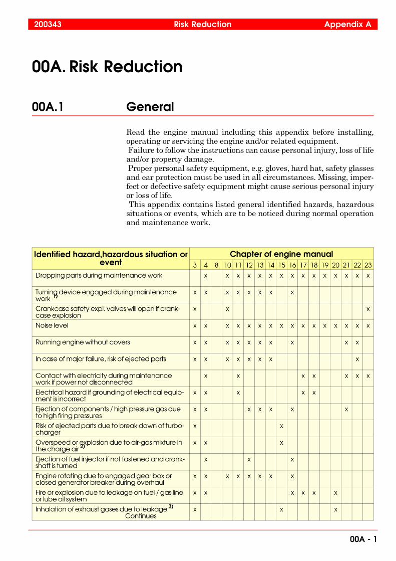
Read the engine manual including this appendix before installing,operating or servicing the engine and/or related equipment. Failure to follow the instructions can cause personal injury, loss of lifeand/or property damage. Proper personal safety equipment, e.g. gloves, hard hat, safety glassesand ear protection must be used in all circumstances. Missing, imper-fect or defective safety equipment might cause serious personal injuryor loss of life. This appendix contains listed general identified hazards, hazardoussituations or events, which are to be noticed during normal operationand maintenance work.
Identified hazard,hazardous situation orevent
Chapter of engine manual3 4 8 10 11 12 13 14 15 16 17 18 19 20 21 22 23
Dropping parts during maintenance work x x x x x x x x x x x x x x x
Turning device engaged during maintenancework 1)
x x x x x x x x
Crankcase safety expl. valves will open if crank-case explosion
x x x
Noise level x x x x x x x x x x x x x x x x
Running engine without covers x x x x x x x x x x
In case of major failure, risk of ejected parts x x x x x x x x
Contact with electricity during maintenancework if power not disconnected
x x x x x x x
Electrical hazard if grounding of electrical equip-ment is incorrect
x x x x x
Ejection of components / high pressure gas dueto high firing pressures
x x x x x x x
Risk of ejected parts due to break down of turbo-charger
x x
Overspeed or explosion due to air-gas mixture inthe charge air 2)
x x x
Ejection of fuel injector if not fastened and crank-shaft is turned
x x x
Engine rotating due to engaged gear box orclosed generator breaker during overhaul
x x x x x x x x
Fire or explosion due to leakage on fuel / gas lineor lube oil system
x x x x x x
Inhalation of exhaust gases due to leakage 3)
Continuesx x x
200343 Risk Reduction Appendix A
00A - 1

Identified hazard,hazardous situation orevent
Chapter of engine manual3 4 8 10 11 12 13 14 15 16 17 18 19 20 21 22 23
Inhalation of exhaust gas dust x x x x x x x
Explosion or fire if flammable gas/vapour isleaking into the insulation box. 4)
x x
Touching of moving parts x x x x x x x x x x x x x x x
High pressure hoses, risk of oil spray. x x x x x x x x x x x x x x
1) Warning light when turning device engaged. 2) Suction air to be taken from gas free space. 3) Require proper ventilation of engine room/plant. 4) Require proper ventilation and/or gas detector in the engine.
00A.1.1 General identified hazards, hazardous situ-ations or events
00A.1.1.1 Hazards that may be due to moving parts
� Running engine without covers, coming in contact with movingparts,
� Touching pump parts during unintentional start of el. drivenpump motor,
� Charger starts to rotate due to draft if not locked during mainte-nance,
� Somebody sticks his hand into the compressor housing when thesilencer is removed and engine running,
� Unexpected movement of valve or fuel rack(s) due to broken wireor soft / hardware failure in the control system,
� Unexpected movement of components,� Turning device engaged during maintenance work,� Turning device not engaged e.g. Turning device removed for
overhaul, during maintenance work could cause rotating crank-shaft,
� Mechanical breakage (of e.g. speed sensor) due to erratic actuatorassembly to engine or electrical connections.
00A.1.1.2 Hazards that may be due to incorrect operating con-ditions
� Overspeed or explosion due to air-gas mixture in the charge air,� Overspeeding due to air-oil mist mixture in the charge air,� Malfunction of crankcase ventilation,� Oil mist detector will trip if water is present in lubricating oil,� Crankcase explosion if oil mist is mixed with “fresh” air during
inspection after an oil mist shut down,
Appendix A Risk Reduction 200343
00A - 2

� Crankcase safety explosion valves will open if there is a crankcaseexplosion.
00A.1.1.3 Hazards that may be due to different leakages, break-down or improper assembly of component
� Fuel or gas pipe will burst and spray fuel / gas,
� Leakage of:— fuel in joints on low and/or high pressure side,— lube oil,— high pressure water on DWI engines,— HT water,— charge air,— exhaust gas,— pressurised air from air container, main manifold or pipes,— high pressure gas and sealing oil on GD engines,
� Fire or explosion due to leakage on fuel line,
� Fire due to oil or fuel / gas leakage,
� Explosion or fire if flammable gas/vapour is leaking into theinsulation box,
� Inhalation of exhaust gases or fuel gases due to leakage,
� Failure of pneumatic stop,
� Ejected components due to:— breakdown of hydraulic tool,— breakdown of hydraulic bolt,— breakdown of turbocharger,— high firing pressures,— major failure,
� Ejection of:— pressurised liquids and gases from the block and pipings,— high pressure fluid due to breakdown of hydraulic tool,— gas due to high firing pressures,— pressurised gases from high pressure gas system,— high pressure fluid due to breakdown of HP sealing oil pipe,— high pressure air during maintenance of oil mist detector main air
supply piping,— cooling water or fuel/lube oil if sensor is loosened while the circuit
is pressurised,— springs during maintenance work,
� Oil spray if running without covers,
� Ejection of fuel injector if not fastened and — turning device engaged and turned.— engine turning due to closed generator breaker/coupling
200343 Risk Reduction Appendix A
00A - 3

00A.1.1.4 Hazards that may be due to electricity or incorrectconnections of electricity
� Fire or sparks due to damage or short circuit in electrical equip-ment,
� Contact with electricity during maintenance work if power notdisconnected,
� Electrical hazard if grounding of electrical equipment is incorrect,
� Electrical shock if electrical equipment has a lead isolation breakor connector damage or is dismantled with power connected,
� Overheating of control system component due to erratic electricalconnections,
� Incorrectly wired or disconnected emergency stop switch,
� Overload of control system components due to damaged controlcircuitry or incorrect voltage,
� Engine not controllable if failure in the shutdown circuitry,
� Unexpected start up or overrun,
� Crankcase explosion if:— engine not safeguarded at high oil mist levels, due to energy supply
failure,— engine not (fully) safeguarded at high oil mist levels, due to failure
in oil mist detector circuitry,— engine not (fully) safeguarded at high oil mist levels, due to erratic
electrical connector or leakage in pipe connection.
00A.1.1.5 Other hazards and hazardous situations where it’s es-pecially important to use personal safety equipment
� Slip, trip and fall,
� Water additives and treatment products (see appendix 02A, sec-tion 02A.4),
� Touching the insulation box, turbo-charger, pipes exhaust mani-fold or (other) unprotected parts without protection during engineoperation,
� Dropping parts during maintenance work,
� Starting maintenance work too early i.e. causing risk when han-dling hot components,
� Neglecting use of cranes and/or lifting tools,
� Not using proper tools during e.g. maintenance work,
� Contact with fuel oil or oily parts during maintenance work (seeappendix 02A),
� Noise level,
� Touching or removing Turbocharger insulation,
� Preloaded fixation springs during check / replacement of sensor.
Appendix A Risk Reduction 200343
00A - 4

00B. Welding Precautions
00B.1 Precautions General
Main principles:• Prevent uncontrolled current loops• Prevent radiation• Prevent sparkles flying around• If convenient, disconnect all global signals like power supply, data
communication etc.
00B.1.1 Preventing uncontrolled current loops
Welding current path must always be checked, there should be astraight route from the welding point back to the return connection ofthe welding apparatus.The biggest current is always going where it meets the lowest resis-tance, in certain cases the return current can therefore go via groundingwires and electronics in the control system.To avoid this, the distance between the welding point and the returnconnection clamp of the welding apparatus should always be shortestpossible and without electronic components in the returning loop path.Attention must be paid to the connectivity of the return connectionclamp, a bad contact might also cause sparkles and radiation.
00B.1.2 Preventing Radiation
The welding current and the arc is emitting a wide spectrum ofelectromagnetic radiation. This might cause damages on sensitiveelectronic equipment.To avoid these damages all cabinets and terminal boxes must be keptclosed during the welding. Sensitive equipment can also be protectedby means of shielding with a conductive metal plate.Also avoid having the cables of the welding apparatus going in parallelwith wires and cables in the control system. The high welding currentis easily inducting secondary currents in other conductive materials.
00B.1.3 Preventing damage due to sparkles
Sparkles are commonly flying around from the welding arc. Fewmaterials withstand the heat from these sparkles. Therefore all cabi-nets and terminal boxes should be kept closed during the welding.Sensors, actuators, cables and other equipment out on the engine mustbe protected by means of proper protection.
200147 Welding Precautions Appendix B
00 - 1

Sparkles can also be a problem after they have cooled down, i.e. causingshort circuits, sealing problems etc.
00B.2 Precaution checklists
00B.2.1 Checklists General
The checklists (preferable glued to a plastic plate) in this chaptershould be put into the engines cabinet for respective system type. Thechecklist must be easily visible and accessible when opening thecabinet.
00B.2.2 Basic ECU (Despemes/Spemos) checklist
The following precautions must be paid attention to before welding inthe vicinity of a basic ECU system:• Close the cover of the cabinet• Deactive the system by disconnecting all external connectors
(X1...X4).• If convenient, protect cables, sensors and other equipment from
sparkles with a proper metal sheet.
00B.2.3 WECS 2000 checklist
The following precautions must be paid attention to before welding inthe vicinity of a WECS 2000 control system:• Close the covers of the cabinet and all the distributed units.• Deactivate the system by disconnecting all external connectors
(X1...X6).• If convenient, protect cables, sensors and other equipment from
sparkles with a proper metal sheet.
00B.2.4 WECS 3000 checklist
The following precautions must be paid attention to before welding inthe vicinity of a WECS 3000 control system:• Deactive the system by disconnecting all external connectors
(X1...X5).• Do not connect the welding apparatus return line to the alu-
minium profile containing CCU’s, KDU’s and ignition modules.The profile is used as a common ground for these modules.
• Open all terminal fuses (F1...F20) in the cabinet.• Close the covers of the cabinet and all the distributed units.• If convenient, protect cables, sensors and other equipment from
sparkles with proper metal sheet.
Appendix B Welding Precautions 200147
00 - 2

00B.2.5 WECS 7000/8000 checklist
The following precautions must be paid attention to before welding inthe vicinity of a WECS 7000 or 8000 control system:• Deactive the system by disconnecting all external connectors
(X1...X6).• If the welding point is close to (approximately within a radius of
2 m) an electronic module (SSM-701, SSM-558, CCD/PDM, Censeetc.) disconnect all connectors of the unit
• Close the covers of the cabinet• Disconnect the interconnections between the harnesses and the
cabinet.• If convenient, protect harnesses, cables, sensors and other equip-
ment from sparkles with a proper metal sheet.
200147 Welding Precautions Appendix B
00 - 3

Appendix B Welding Precautions 200147
00 - 4

01. Main Data, Operating Data and General Design
01.1 Main data for Wärtsilä 34 SG
Cylinder bore . . . . . . . . . . . . . . . . . . . . . . . . . . . . . . . . . . . . . 340 mmStroke . . . . . . . . . . . . . . . . . . . . . . . . . . . . . . . . . . . . . . . . . . . 350 mmPiston displacement per cylinder . . . . . . . . . . . . . . . . . . . . . . 31.78 l
Firing orderEngine type Clockwise rotation Counter-clockwise rotation
12V34 A1-B1-A5-B5-A3-B3-A6-B6-A2-B2-A4-B4
A1-B4-A4-B2-A2-B6-A6-B3-A3-B5-A5-B1
16V34 A1-B1-A3-B3-A7-B7-A4-B4-A8-B8-A6-B6-A2-B2-A5-B5
A1-B5-A5-B2-A2-B6-A6-B8-A8-B4-A4-B7-A7-B3-A3-B1
18V34 A1-B1-A7-B7-A4-B4-A2-B2-A8-B8-A6-B6-A3-B3-A9-B9-A5-B5
A1-B5-A5-B9-A9-B3-A3-B6-A6-B8-A8-B2-A2-B4-A4-B7-A7-B1
Normally the engine rotates clockwise.
Lubricating oil volume in the engineEngine type 12V34 16V34 18V34
App. oil volume in litresNormal sumpDeep sump
18752825
24053620
26704020
Oil volume betweenmax. and min. marks c. litres/mm
4.6 6.1 6.9
App. cooling water volume in the engine in litresEngine only 740 950 1060
Engine and coolingsystem
950 1220 1360
34SG-9701 Main Data, Operating Data and General Design
01 - 1

01.2 Recommended operating data
Apply to normal operation at nominal speed.
Normal values Alarm (stop) limits
Load 100 % 30 - 100 %
Temperatures, (°C)Lube oil before engine 62 - 70 80
Lube oil after engine 10 - 13 higher
HT water after engine 91 - 100 100 (105)
HT water before engine 5 - 8 lower
HT water rise over turbocharger
8 - 12 (15)
LT water before engine 28 - 38
Charge air in air receiver 40 - 60 70 (80)
Exhaust gas after cylinder See test records 550 (580)
Preheating of HT and LT water
70
Gauge pressures (bar)Lube oil before engineat a speed of 600 RPM(10.0 r/s)
3.5 3.5 (2.5)
720 RPM (12.0 r/s) - 750(12.5 r/s)
4.5 - 5.5 3.5 (2.5)
HT/LT water beforeHT/LT pump (=static)
0.7 - 1.5
HT water before engine 2.2 - 4.8 (x) 2.0
LT water beforecharge air cooler
2.2 - 4.4 (x) 2.0
Fuel before engine 3
Starting air max. 10.3
Charge air See test records
Other pressures (bar)Opening pressure ofsafety valve on lube oilpump
6 - 8
Visual indicator andelectronic transducerfor high pressure dropover lube oil filter andfuel filter
1.2 - 1.8
(x) Depending on speed and installation.
Main Data, Operating Data and General Design 34SG-9701
01 - 2
01.3 Reference conditions
Reference conditions according to:Air pressure . . . . . . . . . . . . . . . . . . . . . . . . . . . . . . 100 kPa (1.0 bar) Ambient temperature . . . . . . . . . . . . . . . . . . . . . . . . . . 303 K (30°C)Relative air humidity. . . . . . . . . . . . . . . . . . . . . . . . . . . . . . . . . . 30 %Cooling water temperature of charge air cooler . . . . . 308 K (35°C)
In case the engine power can be utilized under more difficult conditionsthan those mentioned above, it will be stated in the sales documents.Otherwise, the engine manufacturer can give advice about the correctoutput reduction. As a guideline additional reduction may be calculatedas follows:
Reduction factor = (a + b + c) %
a = 0.5 % for every °C the ambient temperature exceeds the statedvalue in the sales documents.b = 1 % for every 100 m level difference above stated value in the salesdocuments.c = 1 % for every °C the cooling water of the charge air cooler exceedsthe stated value in the sales documents.
01.4 General engine design
The engine is a turbocharged intercooled 4-stroke lean-burn gas en-gine.The engine block is cast in one piece. The main bearings are hanging.The main bearing cap is supported by two hydraulically tensioned mainbearing screws and two horizontal side screws. The charge air receiver is cast into the engine block as well as thecooling water header. The crankcase covers, made of light metal, sealagainst the engine block by means of rubber sealings. The lubricating oil sump is welded.The cylinder liners are designed with high collars and drilled coolingholes. The cooling effect is optimised to give the correct temperature ofthe inner surface. The liner is provided with an anti-polishing ring in the upper part ofthe bore to eliminate the risk of bore polishing.The main bearings are fully interchangeable trimetal or bimetalbearings which can be removed by lowering the main bearing cap. Ahydraulic jack is provided for every main bearing to lower and lift themain bearing cap.The crankshaft is forged in one piece and is balanced by counter-weights as required.
34SG-9701 Main Data, Operating Data and General Design
01 - 3

The connecting rods are drop forged. The big end is split and thesmall end bearing is stepped to achieve large bearing surfaces. The bigend bearings are fully interchangeable trimetal or bimetal bearings.The pistons are of composite type fitted with a Wärtsilä Dieselpatented skirt lubricating system. The top ring grooves are hardened.Cooling oil enters the cooling space through the connecting rod. Thecooling spaces are designed to give an optimal shaker effect.The piston ring set consists of two chrome-plated compression ringsand one chrome-plated, spring-loaded oil scraper ring.The cylinder head, made of special cast iron, is fixed by four hyd-raulically tensioned screws. The head is of the double deck design andcooling water is forced from the periphery towards the centre givingefficient cooling in important areas.The inlet valves are stellited and the stems are chromium-plated.The valve seat rings are made of a special cast iron alloy and arechangeable.The exhaust valves, also with stellited seats and chromium-platedstems, seal against the directly cooled valve seat rings.The seat rings, made of a corrosion and pitting resistant material, arechangeable.The camshafts are made up from one-cylinder pieces with integratedcams. The bearing journals are separate pieces and thus it is possibleto remove a camshaft piece sideways. The turbochargers are located at the free end of the engine. On a V-engine there are two chargers, one for each bank.The charge air coolers are made as removable inserts, on theV-engines two identical ones.The lubricating oil system includes a gear pump, oil filter, coolerwith thermostat valve (not in V-engine), centrifugal bypass filter andan electrically driven prelubricating pump. The oil sump is dimen-sioned for the entire oil volume needed, and all cylinder numbers canbe run in wet sump configuration. Dry sump running is also possible.The starting system. The engine is provided with two air drivenstarting motors.
Main Data, Operating Data and General Design 34SG-9701
01 - 4

Cross-section of Wärtsilä 34SG, V-engine
Fig 01-1 3201549539
34SG-9701 Main Data, Operating Data and General Design
01 - 5

Main Data, Operating Data and General Design 34SG-9701
01 - 6

02. Fuel, Lubricating Oil, Cooling Water
02.1 Fuel
02.1.1 General
The engine is designed to operate on natural gas. The maximum limitsof gas characteristics for a certain engine are stated in the documenta-tion delivered with the engine.
02.1.2 Gas quality
The Wärtsilä®34SG engine is designed for running on natural gasqualities according to the following specification:
Gas quality, maximum limitsLower Heating Value LHV 1), min. 24 MJ/m3
N
Methane number (MN) See installation specific instructions
Methane content, CH4, min. 70 vol-%
Hydrogen sulphide, H2S 0.05 vol-%
Hydrogen, H2 2) 3 vol. %
Water and hydrocarbon conden-sates before the engine
Not allowed
Ammonia 25 mg/m3N
Chlorines + Fluorines 50 mg/m3N
Particles or solids content *) 50 mg/m3N
Particles or solids size *) 5 �m
Gas inlet temperature 0 - 50°C
*) Content of gas in engine inlet
1) Lower Heating Value corresponds to the energy content of thegas. If the LHV is lower than specified above, the engine output has tobe adjusted or a higher gas pressure to the engine is needed.
Methane Number is a scale for evaluation of the knock resistance ofthe fuel. A higher number means better knock resistance. If thecomponents of the fuel gas are known, the methane number can becalculated. Heavier hydrocarbons as ethane, propane and butane willlower the methane number. If the methane number does not match the requirements, the engineshould be derated according to special instructions.
34SG-200303-03 Fuel, Lubricating Oil, Cooling Water
34SG 02 - 1

Carbon dioxide and nitrogen will increase the methane number.
2) Hydrogen contents above 3 vol-% must be agreed on case by casebasis.Hydrogen sulphide H2S may cause corrosion on the gas handlingequipment.
Particles can be the reason for improper sealing and function of thegas handling equipment. The gas regulating unit should contain asuitable filter.
NOTE! During dismantling and assembly of the gas components, specialcare should be taken in order to avoid foreign particles entering thegas system.
02.2 Lubricating oil
02.2.1 System oil characteristics
Viscosity. Viscosity class SAE 40.Viscosity index (VI). Min. 95Alkalinity (BN). Lubricants with a BN of 4 - 7 mg KOH/g have to beused.Sulphated ash level. The content of sulphated ash in gas enginelubricants is a very important property. Too high ash content can causepreignition, knocking and spark plug fouling, while too low ash contentcan lead to increased valve wear. Low ash lubricants with sulphatedash level of max. 0.6 w-% have to be used.Additives. The oils should contain additives that give good oxidationstability, corrosion protection, load carrying capacity, neutralization ofacid combustion and oxidation residues, and should prevent depositformation on internal engine parts (piston cooling gallery, piston ringzone and bearing surfaces in particular).Foaming characteristics. Fresh lubricating oil should meet thefollowing limits for foaming tendency and stability (according to theASTM D 892-92 test method):� Sequence I: 100/0 ml� Sequence II: 100/0 ml� Sequence III: 100/0 mlIn this test a certain amount of air is blown through the lubricating oilsample. The first number in the results is the foam volume after ablowing period of 5 minutes and should be less than or equal to 100 ml.The second number is the foam volume after a settling period of 10minutes and should always be 0 ml. Sequences I and III are performed at a temperature of 24°C andsequence II at a temperature of 93.5°C.
Fuel, Lubricating Oil, Cooling Water 34SG-200303-03
02 - 2 34SG

Base oils. Use of virgin base oils is only allowed, i.e. recycled or refinedbase oils are not allowed.
02.2.2 Lubricating oil qualities
Lubricating oil is an integrated engine component and thus the qualityof it is upmost important. All lubricating oils, which have been ap-proved for use in Wärtsilä® 34SG engine type, have gone through anapproval test according to the engine manufacturer’s procedure. The use of approved lubricating oil qualities during the warrantyperiod is mandatory and is also strongly recommended after thewarranty period. The list of approved lubricating oils can be found in the end of thischapter.
Attention! Before using a lubricating oil not listed in the table, the enginemanufacturer must be contacted. Lubricating oils that are notapproved have to be tested according to the engine manufac-turer’s procedure!
Note! Never blend different oil brands unless approved by the oil supplierand during the warranty period, by the engine manufacturer.
02.2.3 Maintenance and control of the lubricating oil
a) During the first year of operation it is advisable to take samples of thelubricating oil at 500 operating hours intervals. The sample should besent to the oil supplier for analysis. On the basis of the results it ispossible to determine suitable intervals between oil changes. Frequentoil analysis at 500 - 1000 operating hours intervals is also recom-mended after the first year of operation to ensure safe engine operation. To be representative of the oil in circulation, the sample should betaken with the engine in operation at the sampling cock locatedimmediately after the oil filter on the engine, in a clean containerholding 0.75 - 1 litre. Take samples before, not after adding new oil tocompensate for consumption. Before filling the container, rinse it withthe oil from which the sample is to be taken. In order to make a complete assessment of the condition of the oil inservice, the following details should be furnished with the sample:Installation, engine number, oil brand, engine operating hours, num-ber of hours the oil has been in use, where in the system sample wasdrawn, type of fuel, any special remarks. Oil samples with no informa-tion except installation and engine number are close to valueless. When estimating the condition of the used oil, the following propertiesshould be observed. Compare with guidance values (type analysis) fornew oil of the brand used.
34SG-200303-03 Fuel, Lubricating Oil, Cooling Water
34SG 02 - 3

Viscosity. Should not decrease by more than 20 % and not rise by morethan 25 % above the guidance value at 100°C. Should not decrease by more than 25 % and not rise by more than50 % above the guidance value at 40°C.Water content. Should not exceed 0.3 %. A value higher than 0.3%can not be accepted for longer periods, but measures must be taken;either centrifuging or oil change.BN (Base Number). The minimum allowable BN value of a used oilis 50 % of the nominal value of a new oil.TAN (Total Acid Number). Should not increase by more than2.5 mg KOH/g compared to nominal value of a new oil.Insolubles. The quantity allowed depends on various factors. The oilsupplier’s recommendations should be followed. However, an n-Pentaneinsoluble value above 0.5 w-% calls for attention. A value higher than1.0 w-% cannot be accepted for longer periods.Nitration and oxidation. If nitration level exceeds 20 Abs/cm and/oroxidation level exceeds 25 Abs/cm, oil must be changed. In general it can be said that the changes in the analysis give a betterbasis of estimation than the absolute value. Fast and great changesmay indicate abnormal operation of the engine or of a system.
b) Compensate for oil consumption by adding max. 10 % new oil at atime. Adding larger quantities can disturb the balance of the used oilcausing, for example, precipitation of insolubles. Measure and recordthe quantity added. Attention to the lubricating oil consumption maygive valuable information about the engine condition. A continuousincrease may indicate that piston rings, pistons and cylinder liners aregetting worn, and a sudden increase motivates pulling the pistons, ifno other reason is found.
c) Guidance values for oil change intervals are to be found in chapter04. Intervals between changes are influenced by system size (oilvolume), operating conditions, fuel quality and total oil consumption.
When changing oil the following procedure is recommended:1 Empty oil system while oil is still hot. Be sure that oil filters and
coolers are also emptied.
2 Clean oil spaces, including filters and camshaft compartment. In-sert new filter cartridges.
3 Fill a small quantity of new oil in the oil sump and circulate with thepre-lubricating pump. Drain!
4 Fill required quantity of oil in the system, see chapter 01, section 01.1. Oil samples taken at regular intervals analyzed by the oil supplier,and the analysis results plotted as a function of operating hours is anefficient way of predicting oil change intervals. Send or ask the oil supplier to send copies of oil analyses to the enginemanufacturer who will then assist in the evaluation.
Fuel, Lubricating Oil, Cooling Water 34SG-200303-03
02 - 4 34SG
02.2.4 Lubricating oils for turbochargers
Please note that different types of turbochargers can be used for theengine. The chargers has a common lubricating oil system with theengine, see chapter 15. See also attached manufacturers instructionfor the turbocharger.
02.2.5 Lubricating oils for engine turning device
It is recommended to use EP-gear oils, viscosity 400-500 cSt at40 °C=ISO VG 460 as lubricating oils for the turning device. Thelist of lubricating oils for the engine turning device approved bythe turning device manufacturer can be found in the end of thischapter.
02.3 Cooling water
02.3.1 General
In order to prevent corrosion, scale deposits or other deposits in closedcirculating water systems, the water must be treated with additives. Before treatment, the water must be limpid and meet the specifica-tion found in the end of this chapter. Further, the use of an approvedcooling water additive or treatment system is mandatory.
Caution! Distilled water without additives absorbs carbon dioxide from theair, which involves great risk of corrosion.
Sea water will cause severe corrosion and deposit formation even ifsupplied to the system in small amounts. Rain water has a high oxygen and carbon dioxide content; great riskof corrosion; unsuitable as cooling water. If risk of frost occurs, please contact the engine manufacturer for useof anti-freeze chemicals. Fresh water generated by a reverse osmosis plant often has a highchloride content (higher than the permitted 80 mg/l) causing corrosion.
Caution! The use of glycol in the cooling water is not recommended, if it isnot necessary. Since glycol alone does not protect the engineagainst corrosion, additionally an approved cooling water additivemust always be used!
34SG-200303-03 Fuel, Lubricating Oil, Cooling Water
34SG 02 - 5

02.3.2 Additives
As additives, use products from well-known and reliable suppliers withvast distribution nets. Follow thoroughly the instructions of the supplier.
Attention! The use of emulsion oils, phosphates and borates (sole) is notaccepted!
In an emergency, if compounded additives are not available, treat thecooling water with sodium nitrite (NaNO2) in portions of 5 kg/m3. Toobtain a pH value of 9, add caustic soda (NaOH), if necessary.
Attention! Sodium nitrite is toxic.
Fuel, Lubricating Oil, Cooling Water 34SG-200303-03
02 - 6 34SG
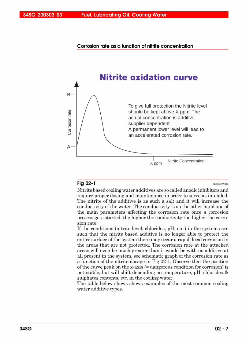
Corrosion rate as a function of nitrite concentration
Nitrite based cooling water additives are so called anodic inhibitors andrequire proper dosing and maintenance in order to serve as intended.The nitrite of the additive is as such a salt and it will increase theconductivity of the water. The conductivity is on the other hand one ofthe main parameters affecting the corrosion rate once a corrosionprocess gets started, the higher the conductivity the higher the corro-sion rate.If the conditions (nitrite level, chlorides, pH, etc.) in the systems aresuch that the nitrite based additive is no longer able to protect theentire surface of the system there may occur a rapid, local corrosion inthe areas that are not protected. The corrosion rate at the attackedareas will even be much greater than it would be with no additive atall present in the system, see schematic graph of the corrosion rate asa function of the nitrite dosage in Fig 02-1. Observe that the positionof the curve peak on the x-axis (= dangerous condition for corrosion) isnot stable, but will shift depending on temperature, pH, chlorides &sulphates contents, etc. in the cooling water. The table below shows shows examples of the most common coolingwater additive types.
B
A
Cor
rosi
on r
ate
X ppm Nitrite Concentration
To give full protection the Nitrite level should be kept above X ppm. The actual concentration is additive supplier dependent. A permanent lower level will lead to an accelerated corrosion rate.
Fig 02-1 3202602002
34SG-200303-03 Fuel, Lubricating Oil, Cooling Water
34SG 02 - 7

Summary of the most common cooling water additivesAdditive Advantages Disadvantages
Sodiumnitrite
- good efficiency, ifdosage is controlledcarefully- small active quantities, 0.5 % by mass- cheap
- suitable as additive except in air cooled heat ex- changers with large soft solder surfaces - toxic- risk of spot corrosion when too low concentration
Nitrite +
borate
- no increased risk ofcorrosion at over doses- innocuous for the skin
- tendency to attack zinc coverings and soft solde- rings- toxic: lethal dosage 3 - 4 g solid nitrite- risk of spot corrosion whentoo low concentration
Sodiumsilicate
- not toxic- harmless to handle
- not active when water velocity exceeds 2 m/s- commercial products very expensive- increased risk of corrosion when too low concen- tration; spot corrosion- limited suitability
Sodiummolybdate
- not toxic- harmless to handle
- more expensive than toxic additives- increased risk of corrosion, if unsufficently dosed- can cause depositformation (molybdates can collect to ferrous sulphates)
Organicand inor-
canic syn-ergisticbased
- not toxic - more expensive thansodium nitrite and molybdatebased additives- big active quantitives bymass
Fuel, Lubricating Oil, Cooling Water 34SG-200303-03
02 - 8 34SG

02.3.3 Treatment
When changing the additive or when entering an additive into a systemwhere untreated water has been used, the complete system must becleaned (chemically) and rinsed before fresh treated water is pouredinto the system. If, against our recommendations, an emulsion oil hasbeen used, the complete system must be absolutely cleaned of oil andgreasy deposits. Evaporated water should be compensated by untreated water; iftreated water is used the content of additives may gradually becometoo high. To compensate for leakage or other losses, add treated water. In connection with maintenance work calling for drainage of thewater system, take care of and reuse the treated water. The list of approved cooling water additives and treatment systemscan be found in the end of this chapter.
Attention! Ask the supplier of the treatment product for instructions abouttreatment procedure, dosage and concentration control.
Most suppliers will provide a test kit for the concentration control.Additionally a frequent laboratory analysis of cooling water at 3 monthsinterval is recommended to ensure safe engine operation.
34SG-200303-03 Fuel, Lubricating Oil, Cooling Water
34SG 02 - 9

Fuel, Lubricating Oil, Cooling Water 34SG-200303-03
02 - 10 34SG
02A. Environmental Hazards
02A.1 General
Fuel oils, lubricating oils and cooling water additives are environmen-tally hazardous. Take great care when handling these products orsystems containing these products. Detailed information and handlinginstructions can be found in the text below.
02A.2 Fuel oils
Prolonged or repetitive contact with the skin may cause irritation andincrease the risk of skin cancer (polyaromatic hydrocarbons, etc.).Fumes, like hydrogen sulphide or light hydrocarbons, that are irritat-ing for eyes and respiratory organs may be released during load-ing/bunkering. Fuel oils are mainly non-volatile burning fluids, butmay also contain volatile fractions. Risk for fire and explosion. Maycause long-term harm and damages in water environments. Risk ofcontamination of the soil and the ground water. Take every appropriatemeasure to prevent water and soil contamination.
02A.2.1 Handling
• Isolate from ignition sources, like sparks from static electricity forexample.
• Avoid breathing evaporated fumes (may contain hydrogen sul-phide, etc.) during pumping and opening of storage tanks forexample. Use gas mask if necessary.
• The handling and storage temperatures must not exceed the flashpoint of the product. Should be stored in tanks or containersdesigned for flammable fluids.
• Must not be let into the sewage system, water systems or onto theground.
• Methane may during long-term storage be formed in tanks, dueto bacterial activities. Risk of explosions during unloading orstorage tank opening for example.
• Cloths, paper or any other absorbent material used to soak upspills are fire hazards. Do not allow these to accumulate.
• Waste that contains the product is hazardous and has to bedisposed of according to directives issued by the local or nationalenvironmental authorities. Collection, regeneration and burningshould be handled by authorized disposal plants.
200321 Environmental Hazards Appendix A
02A - 1

02A.2.2 Personal protection equipment
• Respiratory organs protection: Oil mist: Use respirator, com-bined particle and gas filter. Evaporated fumes (hydrogen sul-phide, etc.): Use respirator, inorganic gas filter.
• Hands protection: Strong, heat and hydrocarbon resistantgloves (nitrile rubber for example).
• Eye protection: Wear goggles if splash risk exists.• Skin and body protection: Wear facial screen and covering
clothing as required. Use safety footwear when handling barrels.Wear protecting clothes if hot product is handled.
02A.2.3 First aid measures
• Inhalation of fumes: Move victim to fresh air, keep warm andlying still. Give oxygen or mouth to mouth resuscitation as needed.Seek medical advice after significant exposures. Inhalation of oilmist: Seek medical advice.
• Skin contact: Hot oil on the skin should be cooled immediatelywith plenty of cold water. Wash immediately with plenty of waterand soap. Do not use solvents, the oil is spread and may beabsorbed into the skin. Remove contaminated clothing. Seekmedical advice if irritation develops.
• Eye contact: Rinse immediately with plenty of water, for at least15 minutes and seek medical advice. If possible, keep rinsing untileye specialist has been reached.
• Ingestion: Rinse mouth with water. Do not induce vomiting, inorder not to risk aspiration into respiratory organs. Seek medicaladvice.
Note! Complete safety data sheets for the specific products used at yourinstallation should be available from the fuel oil delivering com-pany.
Appendix A Environmental Hazards 200321
02A - 2
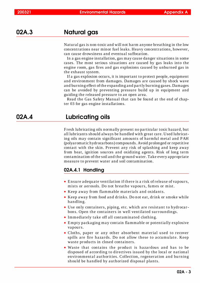
02A.3 Natural gas
Natural gas is non-toxic and will not harm anyone breathing in the lowconcentrations near minor fuel leaks. Heavy concentrations, however,can cause drowsiness and eventual suffocation. In a gas engine installation, gas may cause danger situations in somecases. The most serious situations are caused by gas leaks into theengine room, gas fires and gas explosions caused by unburned gas inthe exhaust system. If a gas explosion occurs, it is important to protect people, equipmentand environment from damages. Damages are caused by shock waveand burning effect of the expanding and partly burning gases. Damagescan be avoided by preventing pressure build up in equipment andguiding the released pressure to an open area. Read the Gas Safety Manual that can be found at the end of chap-ter 03 for gas engine installations.
02A.4 Lubricating oils
Fresh lubricating oils normally present no particular toxic hazard, butall lubricants should always be handled with great care. Used lubricat-ing oils may contain significant amounts of harmful metal and PAH(polyaromatic hydrocarbons) compounds. Avoid prolonged or repetitivecontact with the skin. Prevent any risk of splashing and keep awayfrom heat, ignition sources and oxidizing agents. Risk of long termcontamination of the soil and the ground water. Take every appropriatemeasure to prevent water and soil contamination.
02A.4.1 Handling
• Ensure adequate ventilation if there is a risk of release of vapours,mists or aerosols. Do not breathe vapours, fumes or mist.
• Keep away from flammable materials and oxidants.• Keep away from food and drinks. Do not eat, drink or smoke while
handling.• Use only containers, piping, etc. which are resistant to hydrocar-
bons. Open the containers in well ventilated surroundings.• Immediately take off all contaminated clothing.• Empty packaging may contain flammable or potentially explosive
vapours.• Cloths, paper or any other absorbent material used to recover
spills are fire hazards. Do not allow these to accumulate. Keepwaste products in closed containers.
• Waste that contains the product is hazardous and has to bedisposed of according to directives issued by the local or nationalenvironmental authorities. Collection, regeneration and burningshould be handled by authorized disposal plants.
200321 Environmental Hazards Appendix A
02A - 3

02A.4.2 Personal protection equipment
• Hand protection: Impermeable and hydrocarbon resistantgloves (nitrile rubber for example).
• Eye protection: Wear goggles if splash risk exists.• Skin and body protection: Wear facial screen and covering
clothing as required. Use safety footwear when handling barrels.Wear protecting clothes if hot product is handled.
02A.4.3 First aid measures
• Inhalation of fumes: Move victim to fresh air, keep warm andlying still.
• Skin contact: Wash immediately with plenty of water and soapor cleaning agent. Do not use solvents (the oil is spread and maybe absorbed into the skin). Remove contaminated clothing. Seekmedical advice if irritation develops.
• Eye contact: Rinse immediately with plenty of water, continuefor at least 15 minutes and seek medical advice.
• Ingestion: Do not induce vomiting, in order not to risk aspirationinto respiratory organs. Seek medical advice immediately.
• Aspiration of liquid product: If aspiration into the lungs issuspected (during vomiting for example) seek medical adviceimmediately.
Note! Complete safety data sheets for the specific products used at yourinstallation should be available from the lubricating oil manufac-turer or your local dealer.
02A.5 Cooling water additives, nitrite based
The products are toxic if swallowed. Concentrated product may causeserious toxic symptoms, pain giddiness and headache. Significantintake results in greyish/blue discoloration of the skin and mucusmembranes and a decreasing blood pressure. Skin and eye contact ofthe undiluted product can produce intense irritation. Diluted solutionsmay be moderately irritating.
02A.5.1 Handling
• Avoid contact with skin and eyes.• Keep away from food and drinks. Do not eat, drink or smoke while
handling.• Keep in well ventilated place with access to safety shower and eye
shower.
Appendix A Environmental Hazards 200321
02A - 4
• Soak liquid spills in absorbent material and collect solids in acontainer. Wash floor with water as spillage may be slippery.Contact appropriate authorities in case of bigger spills.
• Bulk material can be land dumped at an appropriate site inaccordance with local regulations.
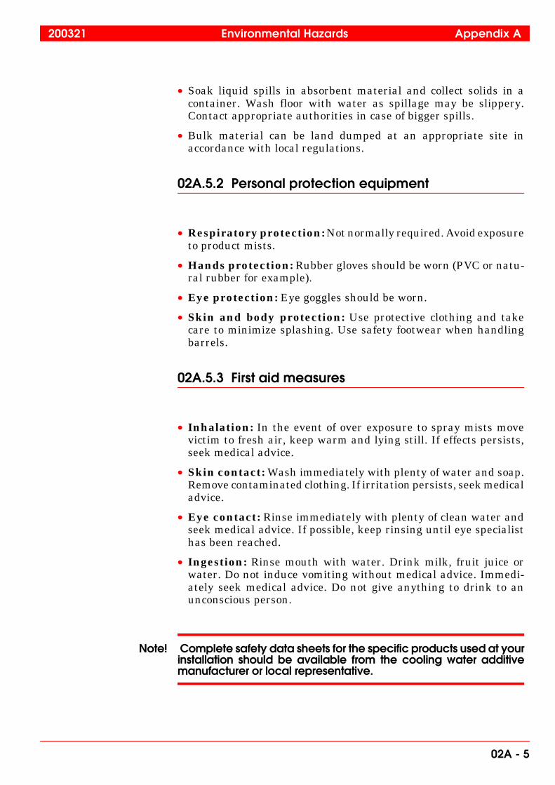
02A.5.2 Personal protection equipment
• Respiratory protection: Not normally required. Avoid exposureto product mists.
• Hands protection: Rubber gloves should be worn (PVC or natu-ral rubber for example).
• Eye protection: Eye goggles should be worn.
• Skin and body protection: Use protective clothing and takecare to minimize splashing. Use safety footwear when handlingbarrels.
02A.5.3 First aid measures
• Inhalation: In the event of over exposure to spray mists movevictim to fresh air, keep warm and lying still. If effects persists,seek medical advice.
• Skin contact: Wash immediately with plenty of water and soap.Remove contaminated clothing. If irritation persists, seek medicaladvice.
• Eye contact: Rinse immediately with plenty of clean water andseek medical advice. If possible, keep rinsing until eye specialisthas been reached.
• Ingestion: Rinse mouth with water. Drink milk, fruit juice orwater. Do not induce vomiting without medical advice. Immedi-ately seek medical advice. Do not give anything to drink to anunconscious person.
Note! Complete safety data sheets for the specific products used at yourinstallation should be available from the cooling water additivemanufacturer or local representative.
200321 Environmental Hazards Appendix A
02A - 5

02A.6 Fly ashes and exhaust gas dust contami-nated components
When handling the fly ashes, exhaust gas dusts and when workinginside the exhaust gas system or when handling any componentcontaminated with exhaust gas dust, at least the following minimumprecautions and safety procedures must be applied:
Note! Inhaling, eye contacts, skin contacts and swallowing of fly ashesand dusts must be avoided.
Employees must be required to study the safety instructions beforethey start to overhaul the exhaust gas system or engine componentsthat have been in contact with exhaust gases.
Note! Spreading and spillage of the fly ashes and dusts to the environmentmust be avoided.
When opening the manholes of the exhaust gas system and speciallythe SCR avoid spreading the dust in the surrounding area. Duringreplacement of components in the exhaust gas system and duringhandling as well as during normal operation of the system, dustspreading must be avoided. Appropriate flue gas dust spillage disposal instructions must beapplied. The dusts collected from the exhaust gas system must beconsidered as hazardous waste and must be treated according to thelocal regulations and legislation.
02A.6.1 Personal protection equipment
• Respiratory organs protection: Toxi particles: Use P3 filter respi-rator or for work inside the SCR or other places in the exhaust gassystem, where the dust concentration is high, a respiration maskwith fresh filtered compressed air supply is recommended.
• Hands protection: Gloves.• Eye protection: Wear goggles.• Skin and body protection: Wear covering clothing. Also when machining or cleaning engine components that have beenin contact with exhaust gases, proper protection according to the abovemust be used. Consideration must also be given to whether the ventilation issuitable for collecting dust from the machining and cleaning of thecomponents.
Appendix A Environmental Hazards 200321
02A - 6

02A.6.2 First aid measures
• Inhalation of ashes: Move victim to fresh air, keep warm and lyingstill. Give oxygen or mouth to mouth resuscitation as needed. Seekmedical advice after significant exposures.
• Skin contact: Hot ash on the skin should be cooled immediatelywith plenty of cold water. Wash immediately with plenty of waterand soap. Do not use solvents, the ash is spread and may beabsorbed into the skin. Remove contaminated clothing. Seekmedical advice if irritation develops.
• Eye contact: Rinse immediately with plenty of water, for at least15 minutes and seek medical advice. If possible, keep rinsing untileye specialist has been reached.
• Ingestion: Rinse mouth with water. Do not induce vomiting, inorder not to risk aspiration into respiratory organs. Seek medicaladvice.
02A.7 Lead in bearings
Lead has valuable lubricating properties and therefore it is incorpo-rated into many bearing alloys.The bearings in Wärtsilä engines consists of lead and are therefore atoxic hazardous waste. Lead containing parts that are not used any-more must be wasted according to local waste disposal plant instruc-tions.
200321 Environmental Hazards Appendix A
02A - 7

02A.8 Fluoride rubber products
02A.8.1 Handling instructions - normal sealing applica-tions
In normal sealing applications the use of fluoride rubber products doesnot cause any health hazards. The handling of products, e.g. installa-tion and service, can be made without any risk – provided that normalindustrial hygiene is applied.
02A.8.2 Handling instructions in case of overheatedseats and valve blow-by
When changing O-rings, for instance after a valve blow-by, operatorshandling the remains of burnt fluoride rubber must wear impenetrableacidproof gloves to protect the skin from the high corrosive remains.Appropriate glove materials are neoprene or PVC. All liquid stateremains must be considered to be extremely corrosive. Neutralisation of the remains can be done by using large amounts ofcalcium hydroxide solution (lime water). Used gloves must be disposedoff.
02A.8.2.1 Use of fluoride rubber products at temperature above275 °C (527 °F)
Fluoride rubber can be used in most applications (up to 275 °C) withoutany substantial degradation or health hazard. Use of or test of fluoriderubber at temperatures above 275 °C must be avoided. If the material,in spite of above recommendations, is exposed to higher temperatures,or in case of an accident, there is a risk that the temperature will riseout of control.
02A.8.3 Special conditions
02A.8.3.1 Grinding dust
Dust and particles which originates from grinding or abrasion (wear)of fluoride rubber can cause the formation of toxic degradation productswhen burned (incinerated). Smoking must therefore be prohibited inareas where there is fluoride rubber dust and particles present.
02A.8.3.2 Fire
In case of a fire, burning fluoride rubber can cause the formation oftoxic and corrosive degradation products (e.g. hydrofluoric acid, car-bonyl fluoride, carbon monoxide and carbon fluoride fragments of lowmolecular weight).Burning (incineration) of fluoride rubber is allowed only when usingapproved incinerators equipped with gas emission reduction systems.
Appendix A Environmental Hazards 200321
02A - 8

02A.8.3.3 DecontaminationOperators handling the remains of burnt fluoride rubber must wearimpenetrable acid-proof gloves to protect the skin from the high corro-sive remains of burnt fluoride rubber. Appropriate glove materials areneoprene or PVC. All liquid state remains must be considered to beextremely corrosive.
02A.8.4 Personal protection equipment
• Hand protection: impenetrable acidproof gloves (neoprene orPVC).
• Inhalation protection: breathing mask.
02A.8.5 First aid measures
• Inhaling: Move the patient from the danger zone. Make sure thathe blows his nose. Consult medical personnel.
• Eye contact: Rinse immediately with water. Contact medicalpersonnel.
• Skin contact: Rinse immediately with water, put a 2%-solution ofcalcium gluconate gel on the exposed skin. If calcium gluconate-gel is not available, continue to rinse with water. Contact medicalpersonnel.
200321 Environmental Hazards Appendix A
02A - 9

Appendix A Environmental Hazards 200321
02A - 10
�WärtsiläTechnology Oy Ab
Finland
,167$//$7,21�0$18$/
This doc is the property of Wärtsilä Technology and shall neither be copied, shown or communicated to a third party without the consent of the owner.
Subtitle Product Made 09.10.1998 KJi / HPH / Hanstén Page Document No Rev
Cooling Systems 20, 32, 46, 64,34SG, 32DF,50DF
Appd. 12.10.1998 EFl / Fontell 1 (4) 4V92A0765 c
Revised date: 10.1.2003 Changed by: Kji /ILe Approved by: VJn / Nurminen D-message No.: 43058
5$:�:$7(5�48$/,7<��$33529('�&22/,1*�:$7(5�$'',7,9(6�$1'
75($70(17�6<67(06
)25�:b576,/b�9$6$�����:b576,/b�����:b576,/b�����:b576,/b�����:b576,/b����:b576,/b���')��:b576,/b���')�$1'�:b576,/b���6*�(1*,1(�7<3(6
5$:�:$7(5�48$/,7<
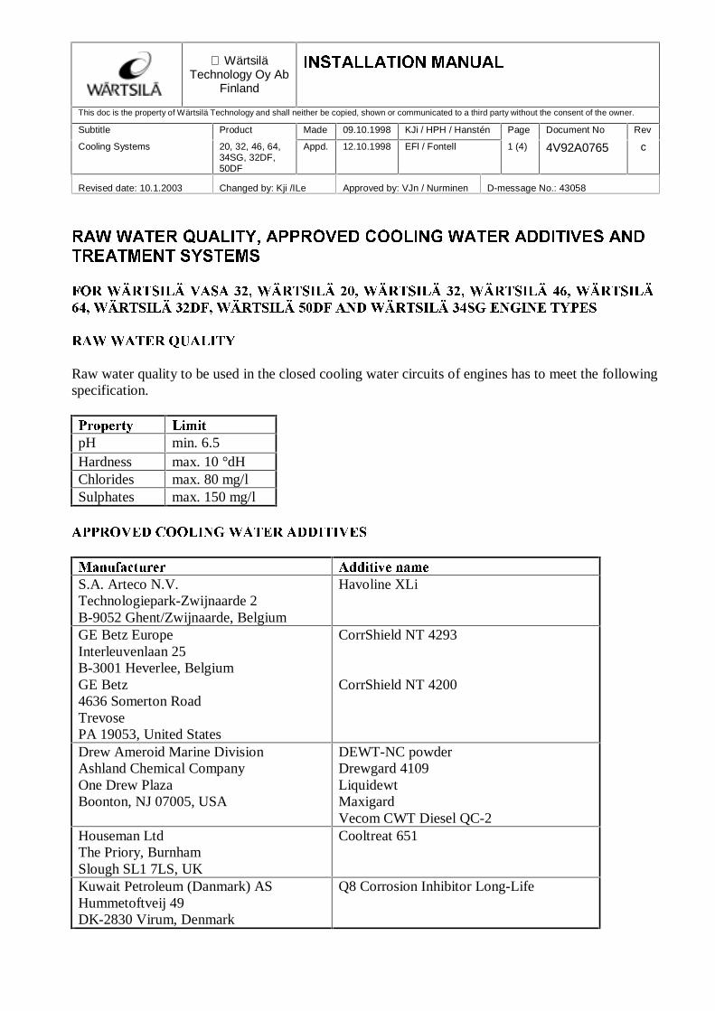
Raw water quality to be used in the closed cooling water circuits of engines has to meet the followingspecification.
3URSHUW\ /LPLWpH min. 6.5Hardness max. 10 °dHChlorides max. 80 mg/lSulphates max. 150 mg/l
$33529('�&22/,1*�:$7(5�$'',7,9(6
0DQXIDFWXUHU $GGLWLYH�QDPHS.A. Arteco N.V.Technologiepark-Zwijnaarde 2B-9052 Ghent/Zwijnaarde, Belgium
Havoline XLi
GE Betz EuropeInterleuvenlaan 25B-3001 Heverlee, BelgiumGE Betz4636 Somerton RoadTrevosePA 19053, United States
CorrShield NT 4293
CorrShield NT 4200
Drew Ameroid Marine DivisionAshland Chemical CompanyOne Drew PlazaBoonton, NJ 07005, USA
DEWT-NC powderDrewgard 4109LiquidewtMaxigardVecom CWT Diesel QC-2
Houseman LtdThe Priory, BurnhamSlough SL1 7LS, UK
Cooltreat 651
Kuwait Petroleum (Danmark) ASHummetoftveij 49DK-2830 Virum, Denmark
Q8 Corrosion Inhibitor Long-Life
Page
2 (4)
Document No
4V92A0765Rev
c
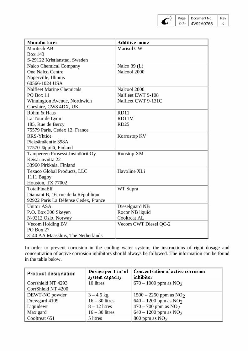
0DQXIDFWXUHU $GGLWLYH�QDPHMaritech ABBox 143S-29122 Kristianstad, Sweden
Marisol CW
Nalco Chemical CompanyOne Nalco CentreNaperville, Illinois60566-1024 USA
Nalco 39 (L)Nalcool 2000
Nalfleet Marine ChemicalsPO Box 11Winnington Avenue, NorthwichCheshire, CW8 4DX, UK
Nalcool 2000Nalfleet EWT 9-108Nalfleet CWT 9-131C
Rohm & HaasLa Tour de Lyon185, Rue de Bercy75579 Paris, Cedex 12, France
RD11RD11MRD25
RRS-YhtiötPieksämäentie 398A77570 Jäppilä, Finland
Korrostop KV
Tampereen Prosessi-Insinöörit OyKeisarinviitta 2233960 Pirkkala, Finland
Ruostop XM
Texaco Global Products, LLC1111 BagbyHouston, TX 77002
Havoline XLi
TotalFinaElfDiamant B, 16, rue de la République92922 Paris La Défense Cedex, France
WT Supra
Unitor ASAP.O. Box 300 SkøyenN-0212 Oslo, Norway
Dieselguard NBRocor NB liquidCooltreat AL
Vecom Holding BVPO Box 273140 AA Maassluis, The Netherlands
Vecom CWT Diesel QC-2
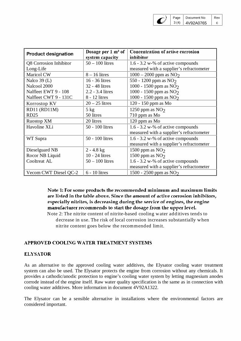
In order to prevent corrosion in the cooling water system, the instructions of right dosage andconcentration of active corrosion inhibitors should always be followed. The information can be foundin the table below.
3URGXFW�GHVLJQDWLRQ 'RVDJH�SHU���Pñ�RIV\VWHP�FDSDFLW\
&RQFHQWUDWLRQ�RI�DFWLYH�FRUURVLRQLQKLELWRU
Corrshield NT 4293CorrShield NT 4200
10 litres 670 – 1000 ppm as NO2
DEWT-NC powderDrewgard 4109LiquidewtMaxigard
3 – 4.5 kg16 – 30 litres8 – 12 litres16 – 30 litres
1500 – 2250 ppm as NO2640 – 1200 ppm as NO2470 – 700 ppm as NO2640 – 1200 ppm as NO2
Cooltreat 651 5 litres 800 ppm as NO2
Page
3 (4)
Document No
4V92A0765Rev
c
3URGXFW�GHVLJQDWLRQ 'RVDJH�SHU���Pñ�RIV\VWHP�FDSDFLW\
&RQFHQWUDWLRQ�RI�DFWLYH�FRUURVLRQLQKLELWRU
Q8 Corrosion InhibitorLong-Life
50 – 100 litres 1.6 - 3.2 w-% of active compoundsmeasured with a supplier’s refractometer
Maricol CW 8 – 16 litres 1000 – 2000 ppm as NO2Nalco 39 (L)Nalcool 2000Nalfleet EWT 9 - 108Nalfleet CWT 9 - 131C
16 - 36 litres32 - 48 litres2.2 - 3.4 litres8 - 12 litres
550 - 1200 ppm as NO21000 - 1500 ppm as NO21000 - 1500 ppm as NO21000 - 1500 ppm as NO2
Korrostop KV 20 – 25 litres 120 - 150 ppm as MoRD11 (RD11M)RD25
5 kg50 litres
1250 ppm as NO2710 ppm as Mo
Ruostop XM 20 litres 120 ppm as MoHavoline XLi 50 - 100 litres 1.6 - 3.2 w-% of active compounds
measured with a supplier’s refractometerWT Supra 50 - 100 litres 1.6 - 3.2 w-% of active compounds
measured with a supplier’s refractometerDieselguard NBRocor NB LiquidCooltreat AL
2 - 4.8 kg10 - 24 litres50 – 100 litres
1500 ppm as NO21500 ppm as NO21.6 - 3.2 w-% of active compoundsmeasured with a supplier’s refractometer
Vecom CWT Diesel QC-2 6 - 10 litres 1500 - 2500 ppm as NO2
1RWH����)RU�VRPH�SURGXFWV�WKH�UHFRPPHQGHG�PLQLPXP�DQG�PD[LPXP�OLPLWVDUH�OLVWHG�LQ�WKH�WDEOH�DERYH��6LQFH�WKH�DPRXQW�RI�DFWLYH�FRUURVLRQ�LQKLELWRUV�HVSHFLDOO\�QLWULWHV��LV�GHFUHDVLQJ�GXULQJ�WKH�VHUYLFH�RI�HQJLQHV��WKH�HQJLQHPDQXIDFWXUHU�UHFRPPHQGV�WR�VWDUW�WKH�GRVDJH�IURP�WKH�XSSHU�OHYHO�Note 2: The nitrite content of nitrite-based cooling water additives tends to
decrease in use. The risk of local corrosion increases substantially whennitrite content goes below the recommended limit.
$33529('�&22/,1*�:$7(5�75($70(17�6<67(06
(/<6$725
As an alternative to the approved cooling water additives, the Elysator cooling water treatmentsystem can also be used. The Elysator protects the engine from corrosion without any chemicals. Itprovides a cathodic/anodic protection to engine’s cooling water system by letting magnesium anodescorrode instead of the engine itself. Raw water quality specification is the same as in connection withcooling water additives. More information in document 4V92A1322.
The Elysator can be a sensible alternative in installations where the environmental factors areconsidered important.

Page
4 (4)
Document No
4V92A0765Rev
c
The installation, operation and maintenance instructions of the manufacturer should always befollowed. The contact information can be found in the table below.
6XSSOLHU 7UHDWPHQW�V\VWHPInternational Watertreatment Maritime ASN-3470 SlemmestadNorway
Elysator

�
���� �
� Wärtsilä Corporation
Finland Technology
INSTALLATION MANUAL
This doc is the property of Wärtsilä Corp. and shall neither be copied, shown or communicated to a third party without the consent of the owner.
Subtitle Product Made 11.08.1998 KJi / JNd Page Document No Rev
- Wärtsilä 34SG Appd. 15.01.1999 UÅd /Åstrand 1 (3) 4V92A0780 c
Revised date: 27.07.2004 Changed by: KJi / ILe Approved by: UÅd D-message No.: 52021
REQUIREMENTS AND OIL QUALITY
SYSTEM OIL REQUIREMENTS AND QUALITY FOR WÄRTSILÄ® 34SG ENGINES Viscosity Viscosity class SAE 40 Viscosity Index (VI) Min. 95 Alkalinity (BN) Lubricating oils with BN of 4-7 mg KOH/g have to be used. Sulphated ash level The content of sulphated ash in gas engine lubricating oils is a very important property. Too high ash content can cause preignition, knocking and spark plug fouling, while too low ash content can lead to increased valve wear. Low ash lubricating oils with sulphated ash level of max. 0.6 % w/w have to be used. Additives The oils should contain additives that give good oxidation stability, corrosion protection, load carrying capacity, neutralisation of acid combustion and oxidation residues and should prevent deposit formation on internal engine parts. Foaming characteristics Fresh lubricating oil should meet the following limits for foaming tendency and stability, according to the ASTM D 892-92 test method: Sequence I: 100/0 ml Sequence II: 100/0 ml Sequence III: 100/0 ml Base oils Use of virgin base stocks is only allowed, i.e. recycled or re-refined base oils are not allowed.

Page
2 (3)
Document No
4V92A0780
Rev
c
CONDEMNING LIMITS FOR USED LUBRICATING OIL
When estimating the condition of used lubricating oil, the following properties along with the corresponding limit values must be noted. If the limits are exceeded, measures must be taken. Compare also with guidance values for fresh lubricating of the brand used.
PROPERTY UNIT LIMIT TEST METHOD Viscosity cSt at 40 °C max. 50% increase ASTM D 445 Viscosity cSt at 100 °C max. 25% increase ASTM D 445 Water % V/V max. 0.30 ASTM D 95 or
D 1744 Base Number mg KOH/g max. 50% depletion ASTM D 2896 Total Acid Number mg KOH/g max. 2.5 mg KOH/g
increase ASTM D 664
Insolubles % w/w in n-Pentane
max. 1.0 ASTM D 893b
Oxidation Abs/cm max. 25 IR Nitration Abs/cm max. 20 IR
APPROVED LUBRICATING OIL QUALITIES FOR WÄRTSILÄ® 34SG
NATURAL GAS OPERATION
SUPPLIER BRAND NAME VISCOSITY BN SULPHATED
ASH (w-%) BP Energas NGL SAE 40 4.5 0.45 Castrol Duratec L SAE 40 4.5 0.45 ChevronTexaco Geotex LA SAE 40 5.2 0.45 ExxonMobil Pegasus 705
Pegasus 805 Pegasus 905 Pegasus 1
SAE 40 SAE 40 SAE 40 SAE 40
5.3 6.2 6.2 6.5
0.49 0.50 0.49 0.49
Petro-Canada Sentinel 445 SAE 40 4.7 0.40 Shell Mysella LA 40 SAE 40 5.2 0.45 Total Nateria X 405 SAE 40 5.2 0.45
USE OF NON-APPROVED LUBRICATING OILS: Before using a lubricating oil not listed in the tables above, the engine manufacturer must be contacted. Lubricating oils that are not approved have to be tested according to engine manufacturer’s procedure. Should unapproved lubricating oils be used during the engine warranty period, and there exist no agreement with the engine manufacturer about testing, the engine guarantee does not hold.

Page
3 (3)
Document No
4V92A0780
Rev
c
APPROVED LUBRICATING OILS FOR ENGINE TURNING DEVICE It is recommended to use EP-gear oils, viscosity 400-500 cSt at 40 °C = ISO VG 460 as lubricating oils for turning device.
LUBRICATING OILS FOR ENGINE TURNING DEVICE SUPPLIER BRAND NAME VISCOSITY
cSt at 40 °C VISCOSITY cSt at 100 °C
VISCOSITY INDEX (VI)
Agip Blasia 320 300 23.0 95 BP Energol GR-XP 460 425 27.0 88 Castrol Alpha SP 460 460 30.5 95 ChevronTexaco Meropa 460 460 31.6 100 ExxonMobil Spartan EP 460
Mobilgear 634 460 437
30.8 27.8
96 96
Shell Omala Oil 460 460 30.8 97 Total / Lubmarine Elf Epona Z 460 470 30.3 93

03. Start, Stop and Operation
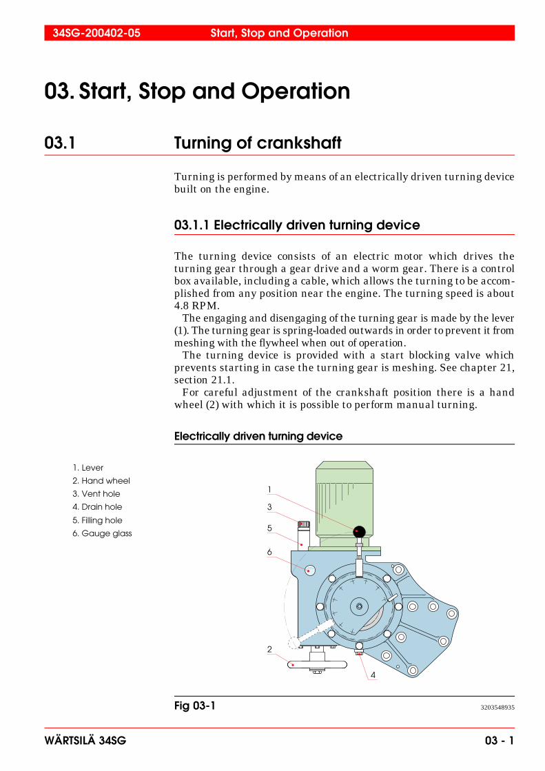
03.1 Turning of crankshaft
Turning is performed by means of an electrically driven turning devicebuilt on the engine.
03.1.1 Electrically driven turning device
The turning device consists of an electric motor which drives theturning gear through a gear drive and a worm gear. There is a controlbox available, including a cable, which allows the turning to be accom-plished from any position near the engine. The turning speed is about4.8 RPM. The engaging and disengaging of the turning gear is made by the lever(1). The turning gear is spring-loaded outwards in order to prevent it frommeshing with the flywheel when out of operation. The turning device is provided with a start blocking valve whichprevents starting in case the turning gear is meshing. See chapter 21,section 21.1. For careful adjustment of the crankshaft position there is a handwheel (2) with which it is possible to perform manual turning.
Electrically driven turning device
1
2
3
5
6
4
1. Lever
2. Hand wheel
3. Vent hole
5. Filling hole
6. Gauge glass
4. Drain hole
Fig 03-1 3203548935
34SG-200402-05 Start, Stop and Operation
WÄRTSILÄ 34SG 03 - 1
03.2 Start
Before starting the engine, check that:• the lubricating oil level is correct• the fuel system is in running order (correct pressure)• both cooling water system circuits, LT and HT water circuit, are
in running order (correct pressures, circulating water preheatedand pre-circulated sufficiently to heat the engine)
• the starting air pressure is 20 bar (normally, 15 bar is stillsufficient to start the engine)
• the starting air system is drained of condensate• the drain pipe of the air cooler casing is open, no leakage.
All covers and protecting shields are to be mounted before starting theengine. Covers should be removed occasionally only for measurementsand checks, and they must be immediately mounted again. Before starting the engine, ensure that possible maintenance andservice operations have been finished and that all persons have left theengine room, boiler room and other risk areas.
Note! Never leave the engine running when covers are removed.
Note! Avoid running the engine on low loads. Misfiring may cause un-burned gas entering the exhaust system and can result in a gasexplosion in the exhaust system.
03.2.1 Manual start
Before the WECS engine control system activates a start request, theengine must be ready for start. The engine modes and the conditionsthat must be fulfilled to get the engine ready for start are explained inchapter 23.
1 Start the prelubricating oil pump to obtain a lubricating oilpressure, above 0.5 bar.
2 Open the valve in the starting air supply system and draincondensate via the blow-off valve. Close the blow-off valve when thereis no more condensate.
3 Open the starting air valve, shut the blow-off valve when thereis no more condensate.
4 Push the start button to initiate the start sequence.
5 The WECS engine control system performs engine and ex-haust pipe ventilation as well as gas system tightness checks beforethe start command is executed
Start, Stop and Operation 34SG-200402-05
03 - 2 WÄRTSILÄ 34SG
Note! Re-start of the engine is possible after the ventilation sequence ofthe exhaust system is finished. The exhaust system is equipped withautomatic ventilation and it will stay open for a while (see installationdocumentation) after the stop. During this time the start will beblocked.
Note! Despite the safety system, there is a risk of gas explosion. To avoidpossible accidents, no-one should remain in the engine room andboiler/silencer room during an engine start.
6 Check immediately after start that the pressure and tempera-ture values are normal. Check that all cylinders are firing, if not,the engine must be stopped and the misfiring cylinders shouldbe checked.
03.2.2 Automatic start
See installation specific documentation.
03.3 Stop
03.3.1 Manual stop
1 Engines with built-on cooling water pump: Idling of the en-gine before stopping is not possible. Engines with separate coolingwater pump: Idling of the engine before stopping is not possible, butthe water pump should run for some 5 min more.
2 Stop the engine by pushing the stop button. Normally when thestop order is given the engine starts to decrease the load automaticallyand when the load is near zero the engine stops. The time of slowingdown offers a good opportunity to detect possible disturbing sounds.
03.3.2 General
Caution! When overhauling the engine, make absolutely sure that the auto-matic start and the priming pump are disconnected. Make also surethat the starting air shut-off valve located before main starting valveis closed. Otherwise it might cause engine damage and/or per-sonal injury.
The lubricating oil system on a stopped engine should be filled withoil every second day by priming the engine. At the same time, turn thecrankshaft into a new position. This reduces the risk of corrosion onjournals and bearings when the engine is exposed to vibrations.
34SG-200402-05 Start, Stop and Operation
WÄRTSILÄ 34SG 03 - 3

03.4 Normal operation supervision
If an alarm limit is reached and an alarm is activated, the engine situationis already serious. All necessary countermeasures must be taken to removethis emergency condition and return to normal operating conditions. Asthe abnormal operating situation may cause damages to the engine, allefforts must be put into returning to the normal operating situation insteadof just waiting for an automatic shut down of the engine.
03.4.1 Every second day or after every 50 running hours
1 Read all temperatures and pressures and, at the same time,the load of the engine. All temperatures are more or less dependent onthe load, and the lubricating oil, cooling water pressures (built-onpumps) are dependent on the speed. Therefore, always compare thevalues read with those at corresponding load and speed in the Accep-tance Test Records and curves. Guidance values are stated inchapter 01. The charge air temperature should, in principle, be as low as possibleat loads higher than 60 %, however, not so low that condensation occurs,see Fig 03-2.
2 Check the indicator for pressure drop over gas filters. Whenthe pressure drop over the filters increases, the gas feed pressure to theengine might become too low and the output of the engine must bedecreased. Too high of a pressure drop may also result in deformationof filter cartridges.
3 Check the indicator for pressure drop over the lubricating oilfilter. Too large of a pressure drop indicates clogged filter candles,which results in reduced oil filtration when the by-pass valve is open.Reduced oil filtration results in increased wear. Inspect andclean/change the filter candles.
4 Check the oil level in the oil sump/oil tank. Estimate the ap-pearance and consistency of the oil. A simple control of the watercontent: A drop of oil on a hot surface (about 150°C), e.g. a hot-plate. Ifthe drop keeps “quiet”, it does not contain water; if it “frizzles” itcontains water. Compensate for oil consumption by adding max. 10 %fresh oil at a time.
5 Check the ventilation (de-aerating) of the engine cooling watersystem. Check that the leakage from the telltale hole of the coolingwater pumps are normal (slight).
6 Check that the drain pipes of the air coolers are open.
7 Check that the telltale holes of the oil coolers and the coolingwater coolers are open.
8 Clean the compressor side of the turbocharger by injectingwater. See the instruction manual of the turbocharger.
Start, Stop and Operation 34SG-200402-05
03 - 4 WÄRTSILÄ 34SG

Condensation in charge air coolers
Example: If the ambient air temperature is 35°C and the relativehumidity is 80 % the water content in the air can be read from the diagram(0.029 kg water/kg dry air). If the air manifold pressure (receiver pres-sure) under these conditions is 2.5 bar, i.e. absolute air pressure in theair manifold is abt. 3.5 bar (ambient pressure + air manifold pressure),the dew point will be 55°C ( from diag.). If the air temperature in the airmanifold is only 45°C, the air can only contain 0.018 kg/kg (from diag.).The difference, 0.011 kg/kg (0.029-0.018) will appear as condensed water.
03.4.2 Once a month or after every 500 running hours
1 Clean the centrifugal lubricating oil filters.
2 Check content of additives in the circulating water.
60
50
40
30
20
10
0
10
20
30
40
50
60
70.01 .02 .03 .04 .05 .06 .07 .08 .09
Water content
Wa
ter d
ew
po
int
˚C
(kg water/kg dry air)
Am
b a
ir te
mp
era
ture
˚C
P=Air manifold pressurebar abs
P=4,5 P=2,5P=3,5P=1,5
f=40f=60 f=80 f=100
f=Relative humidity %
Fig 03-2 3203528930
34SG-200402-05 Start, Stop and Operation
WÄRTSILÄ 34SG 03 - 5
03.4.3 In connection with maintenance work
1 Record the following steps and the running hours in the enginelog:• lubricating oil sampling (record also operating time of oil). Lubric-
ating oil analyses without statement of operating time is of limitedvalue (“go - no go” only)
• lubricating oil changes• cleaning of centrifugal lubricating oil filters• inspection, cleaning/change of the lubricating oil filter candles• inspection, cleaning/change of the gas filter• change of parts in connection with maintenance according to
chapter 04.
2 Disconnect the electronic equipment according to the in-structions in appendix 00B, if any welding is performed on the engine.Keep the return connection near the welding point.
Note! Welding may, if incorrectly performed, cause serious injury on theelectronic engine control system.
03.4.4 General
1 There is no automatic supervision or control arrangement that canreplace an experienced engineer’s observations. LOOK at and LIS-TEN to the engine!
2 Strong gas blow-by past the pistons is one of the most danger-ous things that can occur in an engine. If gas blow-by is suspected, checkthe crankcase pressure. If the pressure exceeds 300Pa (30 mm H2O),check the crankcase venting system, if in order, pull the pistons!
Start, Stop and Operation 34SG-200402-05
03 - 6 WÄRTSILÄ 34SG

03.5 Start after a prolonged stop (more than 8 h)
03.5.1 Manual start
1 Check • the lubricating oil level• the cooling water level in the expansion tank• the raw water supply to heat exchangers• the starting air pressure is min. 18 bar
2 Observe all points in section 03.2.1.
03.6 Start after overhaul
1 Check gas system for leakage.
2 Check the cooling water system for leakage, especially:• the lower part of the cylinder liners• the oil cooler• the charge air cooler
3 Check/adjust the valve clearances. If the camshaft or itsdriving mechanism have been touched, check the valve timing of onecylinder, at least (on each cylinder bank in a V-engine). Guidancevalues, see chapter 06. Check also encoder position at camshaft end.
4 Start the priming pump. Check that lubricating oil appears fromall bearings and lubricating nozzles, from the piston cooling oil outletand from the valve mechanism. Check that there is no leakage fromthe pipe connections inside or outside the engine.
Note! Observe that the crankshaft has to be turned in order to get oilthrough all connecting rods.
5 Rags or tools left in the crankcase, untensioned or unlockedscrews or nuts (those which are to be locked), worn-out self-lockingnuts, may cause total breakdown. Well cleaned oil spaces (oil sump and camshaft spaces) save the oilpump and oil filter.
6 See the instructions in section 03.2 and 03.5 when starting.
34SG-200402-05 Start, Stop and Operation
WÄRTSILÄ 34SG 03 - 7

03.7 Operation supervision after overhaul
1 At the first start, listen carefully for possible jarring sounds. Ifanything is suspected, stop the engine immediately, otherwise stop theengine after 1 minutes idling at normal speed. Check at least thetemperatures of the main and big end bearing and of all other bearingswhich have been opened. If everything is in order, restart.
2 Check that there is no leakage of gas, water or lubricating oil.Especially observe the gas lines and valves.
3 After overhauling, the following instructions are especially im-portant: • Check pressures and temperatures• Check the automatic alarm and stop devices• Check the pressure drop over the gas filter and lubricating oil
filter• Check the oil level in the oil sump/oil tank. Estimate the condition
of the oil• Check the ventilation (de-aerating) of the engine cooling water
system• Check the telltale holes of the coolers• Check the content of additives in the cooling water• Listen for jarring sounds• Check the crankcase pressure• Check the starting air pipes
03.8 Running-in
The running-in of a new engine must be performed according toprogramme in Fig 03-3. It is also recommended that running-in proce-dure is performed after following maintenance jobs.
1 After changing piston rings, pistons or cylinder liners, afterhoning of cylinder liners, follow programme in Fig 03-3 as closely aspossible. If the programme cannot be followed, do not load the enginefully for at least 10 h.
Avoid “running-in” at continuous and constant low load!
The important thing is to vary the load several times. The ring groovewill have a different tilting angle at each load stage, and consequentlythe piston ring a different contact line to the cylinder liner.
Start, Stop and Operation 34SG-200402-05
03 - 8 WÄRTSILÄ 34SG

Running-in programme
03.9 Maintenance of turning device
The turning device needs no other maintenance than change of the gearbox lubricating oil once during the first year of operation. Approvedlubricating oils, see chapter 2. After that, the oil should be changedaccording to chapter 04. Check also that the vent hole (3), Fig 03-1 isopen.
1 Drain old oil, preferably when warm, through the drain hole (4).
2 Rinse the gear box with clean, thinly fluid oil.
3 Fill the gear box with oil (according to the table in chapter 2)through the filling hole (5) until the oil level reaches the level gaugeglass (6). Utmost cleanliness should be observed.
4 Close the oil holes and drive the turning device a few revolu-tions.
5 Check the oil level and fill, if necessary.
1 2 3 4 5 6 7 h
0
10
20
30
40
50
60
70
80
90
100
Engine load %
Operating hours
A After piston overhaulB After change of piston rings, pistons or cylinder liners,
after honing cylinder liners
Stop. Check big end bearing temperatures
End of running-in programme. Engine may be put on normal mode
1
2 2
1
2
Fig 03-3 3203569701
34SG-200402-05 Start, Stop and Operation
WÄRTSILÄ 34SG 03 - 9

Start, Stop and Operation 34SG-200402-05
03 - 10 WÄRTSILÄ 34SG

t®êíëáä®=cáåä~åÇ=ló= Power Plants
Doc. id: WDAAA243558 b Date: 23-Sep-2003 Page: 1 (19) Status: APPROVED Made/Approved: MKO010 / AEK001 Project: WFI-P Power Plant Technology, IN023 Name: Power plant Subject: Wärtsilä safety manual for lean burn gas engine 1 General ...................................................................................................................................... 2 2 Hazardous area classification.................................................................................................... 2
2.1 Classification for engine ......................................................................................................... 2 2.1.1 American Codes ............................................................................................................. 2 2.1.2 European Codes ............................................................................................................. 2 2.1.3 UK Codes........................................................................................................................ 2
2.2 Classification for auxiliary system .......................................................................................... 3 3 Control philosophy ..................................................................................................................... 4
3.1 Start........................................................................................................................................ 4 3.2 Run......................................................................................................................................... 4 3.3 Stop........................................................................................................................................ 4 3.4 Shut down .............................................................................................................................. 4 3.5 Emergency ............................................................................................................................. 5 3.6 Stand-by................................................................................................................................. 5
4 Fire fighting and gas detection system ...................................................................................... 6 4.1 Fire detectors ......................................................................................................................... 6 4.2 Fire fighting equipment........................................................................................................... 6 4.3 Gas detectors......................................................................................................................... 7 4.4 Alarm and shut down system description............................................................................... 7
5 Engine room ventilation ............................................................................................................. 7 6 Emergency lighting .................................................................................................................... 7 7 Gas supply system .................................................................................................................... 7
7.1 Main shut off valve.............................................................................................................. 8 7.2 Gas regulating unit ............................................................................................................. 9
7.2.1 Design............................................................................................................................. 9 7.2.2 Function ........................................................................................................................ 12
7.2.2.1 Normal stop or shut down...................................................................................... 14 7.2.2.2 Emergency............................................................................................................. 14 7.2.2.3 Plant emergency.................................................................................................... 14
7.2.3 Operation of the gas regulating unit.............................................................................. 15 7.2.3.1 Activation of the gas regulating unit ....................................................................... 15 7.2.3.2 Monitoring of the gas regulating unit...................................................................... 15 7.2.3.3 Shutting down the gas regulating unit for maintenance......................................... 16 7.2.3.4 Emergency stop of the gas regulating unit ............................................................ 17
8 Exhaust gas system................................................................................................................. 17 8.1 General ................................................................................................................................ 17 8.2 Piping design........................................................................................................................ 17 8.3 Exhaust gas system ventilation............................................................................................ 18 8.4 Explosion vents .................................................................................................................... 18
Wärtsilä Finland Oy Power Plants
Doc id: WDAAA243558 b Date: 23-Sep-2003 Page: 2 (19) 1 General
This section of manual describes mainly the safety features of auxiliary components i.e. outside engine in the power plant.
2 Hazardous area classification
2.1 Classification for engine In the case of an adequately ventilated enclosure containing gas-fuelled engines it need not be classified solely by reason of the engine fuel. This is the case with a normal power plant installation.
In the case of a gas compressor driven by a gas engine, the engine is seen as an ignition source and the gas compressor is a source of possible gas leak. The possibility of a gas leak is considered to be much higher in a gas compressor, thus, a gas engine driven compressor is classified as hazardous area, normally zone 2 or class I division 2.
The above mentioned statement is based on the following standards:
2.1.1 American Codes American Petroleum Institute
API 500: Recommended Practice for Classification of Locations for Electrical Installations at Petroleum Facilities Classified as Class I, Division 1 and Division 2
• Section 8.2.5 Hydrocarbon-fuelled Prime Movers
National Fire Protection Association
NFPA 37: Standard for Stationary Combustion Engines and Gas Turbines
NFPA 850: Recommended Practice for Fire Protection for Electric Generating Plants and High Voltage Direct Current Converter Stations
2.1.2 European Codes
EN-60079-10 Electrical apparatus for explosive gas atmospheres; part 10 Classification of hazardous
areas
EN-1834-1 Reciprocating internal combustion engines – Safety requirements for design and construction of engines for use in potentially explosive atmospheres – Part II engines for use in flammable gas and vapour atmospheres.
There are no current EU guidelines for gas engine power generation installations; in such a case Internationally recognised codes are accepted.
2.1.3 UK Codes The Institute of Petroleum
IP15 Area classification code of practice for petroleum installations, Model code of safe practice: part 15
Section 8.7 Combustion Engines

Wärtsilä Finland Oy Power Plants
Doc id: WDAAA243558 b Date: 23-Sep-2003 Page: 3 (19) The Institution of Gas Engineers
IGE/UP/3 Gas fuelled spark ignition and dual fuel engines
Section 8.1.7 Electrical Equipment and Supplies
2.2 Classification for auxiliary system Regarding auxiliary gas system, the codes to be followed are EN60079-10, API500 and IGE/SR/25.
From these, it can be derived that zone 2 or class I division 2 is found in the gas piping flange joints in gas regulating unit and flow metering unit (option). The hazardous area around the flange is a sphere whose radius is typically 1 m. In addition, vent piping creates a hazardous area near the roof.
Radius should be checked for each installation, and is affected by the gas pressure and level of ventilation.
Figure 1 shows a typical example of hazardous area classification for gas engine power plant.
Figure 1 Hazardous area classification for a gas engine power plant according to API500.

Wärtsilä Finland Oy Power Plants
Doc id: WDAAA243558 b Date: 23-Sep-2003 Page: 4 (19) 3 Control philosophy
There are different control modes for the power plant. These are:
• Start
• Run
• Stop
• Shut down
• Emergency
• Stand-by
These are discussed briefly below. In addition, different causes for stop, shut down and emergency from power plant as well as different consequences regarding power plant safety are discussed below.
3.1 Start In start mode certain checks are gone through in order to ensure a safe start. The plant control system (PLC) checks for start blocks before engine is allowed to start. After the engine is started following the start sequence the engine mode is changed to running.
3.2 Run In run mode engine output is maintained at the level required by the plant and all engine parameters are monitored and controlled to ensure a safe and reliable operation.
3.3 Stop Stop is activated from WOIS giving an order for engine to stop or it can be done by pressing the stop button in M1 panel. The engine is unloaded and when the load has reached a set value, the generator breaker is opened and a stop command for WECS is given.
The gas regulating unit is closed. See chapter gas regulating unit for more details.
3.4 Shut down Shut down is otherwise the same as the stop mode except that it is initiated by a failure detected by WECS or PLC.
Causes for shut down are:
• start sequence failure
• gas system abnormal
• electrical system fault
• safety relay trip
• WECS shut down signal
• WECS communication failure
• Project specific trip

Wärtsilä Finland Oy Power Plants
Doc id: WDAAA243558 b Date: 23-Sep-2003 Page: 5 (19) Main consequences are:
• Generator breaker opens
• Stop command for WECS is given
• Gas regulating unit is closed
3.5 Emergency
Emergency mode is initiated by a hardwired signal. Emergency mode for power plant is shown in Figure 2.
Emergency can be initiated either by pressing emergency stop push buttons in:
• common panel, which means a plant emergency mode is initiated and all the engines are shut down or
• by engine wise panels, which means an emergency mode is initiated for that engine only
or
by a fire or gas detector.
CFA = common control panelSR
CFC1 CFC2 CFC3
WECS WECS WECS
SR SR SR
Figure 2 A schematic diagram for emergency mode of control system.
SR = safety relay
CFC = engine wise control panel
3.6 Stand-by
Stand-by is a mode in which the power plant waits to be started. To enter this mode, plant needs to be stopped. In case of a shut down or emergency all the faults and alarms need to be cleared before start can proceed.
Wärtsilä Finland Oy Power Plants
Doc id: WDAAA243558 b Date: 23-Sep-2003 Page: 6 (19) 4 Fire fighting and gas detection system
Each country has it’s own fire protection legislation and codes of practise. Therefore, project design is to be reviewed with the local authorities and the system is chosen on a case by case basis.
The power plant is subdivided into separate fire areas for the purpose of limiting the spread of fire, protecting personnel and limiting the resultant consequential damage to the plant.
Fire areas are separated from each other with fire barriers, spatial separation or other approved means.
Media capable of burning in a gas power plant are:
• Gas
• Cables
• Lubrication oil
The main method to prevent a gas fire is to design the gas system safe.
• Main manual gas shut off valve is located outside the engine room
• Automatic shut off valves located inside engine room will shut off the engine specific fuel supply in an engine stop.
• A flexible connection is placed between engine gas piping and auxiliary gas piping. This is required due to vibrations and possible movement of the piping.
• Optionally engine specific gas shut off outside engine room (see chapter 5)
Burning gas must not be extinguished since the remaining unburned gas may explode.
Other possible causes for a fire are taken care of with a fire detecting and fighting system.
4.1 Fire detectors
There are normally at least two fire detectors per location. Fire detector types used are:
• Differential heat detectors
• Optical smoke detectors
The type used and the locations for the detectors will depend on the project and standards to be followed.
4.2 Fire fighting equipment
Fire fighting system consists of:
• Portable dry powder and/or CO2 extinguishers
• Fire hydrants for fire hoses
• Loose fire hose equipment to be connected to fire hydrants
• Permanently connected fire hose reels

Wärtsilä Finland Oy Power Plants
Doc id: WDAAA243558 b Date: 23-Sep-2003 Page: 7 (19) 4.3 Gas detectors The gas detectors are required to detect any gas leak. These are located in a position where a gas leak is most likely to occur and be detected. See Figure 1. These are normally:
• Above gas regulating unit
• At ventilation air outlet at the roof level
4.4 Alarm and shut down system description The gas and fire detection system has a control unit, which receives information from detectors placed in critical locations. If a detector is activated, a fire or a gas leak alarm is given locally and/or remotely, to ensure evacuation of personnel and to initial emergency procedures.
An alarm is given when a gas detector is sensing 10 % of LEL (lower explosion limit).
When a gas detector is sensing 20 % of LEL or above, normally an automatic emergency is initiated for the plant shutting down the gas supply at the engine specific gas regulating units and closing the main shut of valve outside the engine room or engine cell. In case of a fire alarm a plant shut down is initiated, as well.
Gas detectors can also be of the type with one level alarm. In this case exceeding an alarm level of 20 % of LEL an emergency mode is initiated.
An option is that the gas detector or fire detector gives an alarm and the necessary actions are taken by operating personnel.
5 Engine room ventilation
The engine room ventilation system is required in order to supply sufficient combustion air to the engine and to maintain the temperature in the engine room at a suitable level.
Ventilation can be classified as inadequate or adequate. The prerequisite for an engine room to be unclassified area regarding explosion safety is that ventilation shall be adequate at all times including stand by.
An option is that gas system is of special design. In this case the gas supply is closed per each engine outside the engine room. This is done to keep the gas inventory low inside the engine room and thus ventilation is not required in a stand by mode. (See chapter 7.1). In addition, in this design the gas system components up to the gas regulating unit are done with welded joints and thus a possibility of a gas leak is negligible.
6 Emergency lighting
Emergency lighting shall be ex-classified in zoned areas and in engine room or engine cell to reduce the risk of igniting any possible gas/air mixture in the power plant during any emergency.
7 Gas supply system
The gas supply is an essential part for the engine operation. It should be regularly inspected and maintained for correct function and safety.
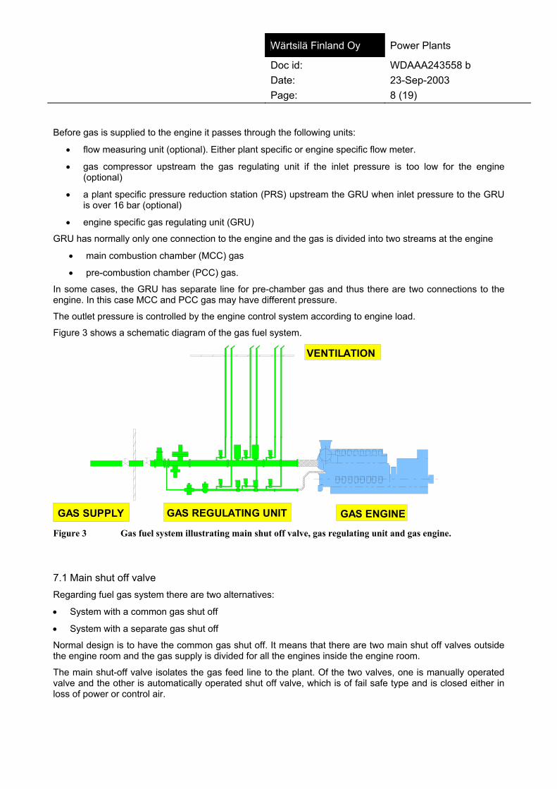
Wärtsilä Finland Oy Power Plants
Doc id: WDAAA243558 b Date: 23-Sep-2003 Page: 8 (19) Before gas is supplied to the engine it passes through the following units:
• flow measuring unit (optional). Either plant specific or engine specific flow meter.
• gas compressor upstream the gas regulating unit if the inlet pressure is too low for the engine (optional)
• a plant specific pressure reduction station (PRS) upstream the GRU when inlet pressure to the GRU is over 16 bar (optional)
• engine specific gas regulating unit (GRU)
GRU has normally only one connection to the engine and the gas is divided into two streams at the engine
• main combustion chamber (MCC) gas
• pre-combustion chamber (PCC) gas.
In some cases, the GRU has separate line for pre-chamber gas and thus there are two connections to the engine. In this case MCC and PCC gas may have different pressure.
The outlet pressure is controlled by the engine control system according to engine load.
Figure 3 shows a schematic diagram of the gas fuel system.
GAS ENGINE
VENTILATION
GAS REGULATING UNITGAS SUPPLY Figure 3 Gas fuel system illustrating main shut off valve, gas regulating unit and gas engine.
7.1 Main shut off valve Regarding fuel gas system there are two alternatives:
• System with a common gas shut off
• System with a separate gas shut off
Normal design is to have the common gas shut off. It means that there are two main shut off valves outside the engine room and the gas supply is divided for all the engines inside the engine room.
The main shut-off valve isolates the gas feed line to the plant. Of the two valves, one is manually operated valve and the other is automatically operated shut off valve, which is of fail safe type and is closed either in loss of power or control air.

Wärtsilä Finland Oy Power Plants
Doc id: WDAAA243558 b Date: 23-Sep-2003 Page: 9 (19) The main shut off valves are located outside the building and marked clearly according to local regulations. In the event of a gas leak, fire or gas explosion the valve should always be closed. In the case of a plant emergency, the automatically operated main shut off valve is closed by a hardwired signal.
An engine specific emergency does not close the main shut off valve. It only closes the slam shut off valves on the GRU and ventilates the gas pipe between the engine and the GRU.
An option is the design that each engine has main shut off valve(s) outside the engine room, i.e., a system with separate gas shut off. In this case the automatic valve is closed in the operating modes:
• Stop
• Shut down
• Emergency shut down
• Plant emergency shut down
7.2 Gas regulating unit Natural gas is supplied from the distribution system and passes through a gas regulating unit - or the “gas train”. The gas regulating unit provides the correct gas admission to the engine by regulating gas feed pressure depending on the engine load. In addition, gas regulating unit performs a leakage test of the main slam shut off valves prior to every engine start.
7.2.1 Design The main components of the GRU are (see Figure 4 and Figure 5):
• Manual ball valve: V01
• Inert gas line, closed with a cap.
• Filter
• Instrumentation such as pressure and temperature gauges and transmitters
• Pressure regulating valve of diaphragm type, pilot operated, self regulating: V07
• Main slam shut-off valves: V15 and V18, fail close
• Ventilating valves: V14, V16, V19 (V14 is of fail close type while the others are of the fail open type)
The electrical components are ex-classified to be suitable for installation in zone 2 or class I division 2, respectively. This is due to possible small leaks in the flanges or other connection, which makes a small hazardous area around the unit flanges or connections.
Gas regulating unit layout drawing is illustrated in Figure 4 and the P&ID is shown in Figure 5.

Wärtsilä Finland Oy Power Plants
Doc id: WDAAA243558 b Date: 23-Sep-2003 Page: 10 (19)
VentVent Vent
Ball valve Filter
Pilot operated
Downstream pipe Electro-pneumatic
Main Pressure Regulator
shut-off valves
Control Air Compressed Air
Figure 4 Typical gas regulating unit layout.
Figure 5 The P&ID of the gas regulating unit.
Vent no 1 Vent no 2

Wärtsilä Finland Oy Power Plants
Doc id: WDAAA243558 b Date: 23-Sep-2003 Page: 11 (19) The GRU includes shut-off valves and ventilation valves, which are located in the vent pipes. These vent pipes are drawn as two separate lines up to the roof (see Figure 5). This is a hazardous area and it is marked on the layouts as such (see Figure 1).
Figure 6 shows the pressure regulator in the GRU.
Figure 6 The pressure regulator with functional units regulator, pilot valve and SAV valve.
The pilot operated pressure regulator is operated using control air from I/P converter.
The regulator consists of the main valve body and the functional units “regulator”, “pilot valve” and “safety shut-off valve” (SAV).
Safety shut-off valve (SAV)
An additional safety shut-off valve may be installed if the inlet pressure to the GRU is higher than 6 bar. The control element of the safety shut-off valve is installed on the inlet side of the body and shuts off the gas flow if the outlet pressure in the main gas line rises above the pre-set limits. On detecting high pressure the SAV measuring diaphragm and the switching bush move into the release position and the ball mechanism set the valve stem free to close the SAV valve.
The safety shut-off valve can only be reopened by hand, after the outlet pressure at the measuring point has been restored to a value below the re-engagement differential. If the SAV valve is closed, it will lead to a shut down of the engine and depressurisation of the piping after regulating valve V07 resulting is the pressure automatically decreased below the re-engagement differential.
Thus the following shall be done:
• Reopen the SAV valve first slowly by dragging slightly (pressures will equalise)
• After equalising open the valve completely
This is required to enable a safe and easy re-engagement of the SAV valve.
There is a feedback signal in the SAV to monitor the valve.

Wärtsilä Finland Oy Power Plants
Doc id: WDAAA243558 b Date: 23-Sep-2003 Page: 12 (19) Figure 7 shows the main slam shut off valves in the GRU.
Compressed Air
Pressure Transmitter
1
2
3
VentVent
PressureSwitch
Figure 7 The shut-off valves with actuator (1), solenoid operated air valve (2) and solenoid operated vent valve (3).
The GRU is equipped with two shut-off valves, installed in series. The valves are operated by admitting compressed air into the actuator cylinders. The valves are closed by a spring when control voltage is cut off and control air released from the actuator cylinders.
Gas trapped between the valves and in the pipe between the last shut off valve and the engine is vented to the atmosphere through the solenoid operated vent valves (3). The vent valves V16 and V19 (additionally V26 and V29 for PCC line) are closed as long as the operating voltage is applied. V14 (and V24 for PCC line) is open as long as the operating voltage is applied. In running mode voltage is not applied to V14 and the valve is closed.
Both the shut-off valves and the vent valves are operated by the PLC.
7.2.2 Function Gas is mixed with the combustion air only in the intake channels in the cylinder head (see Figure 8). This design ensures that only air is present in the charge air manifold, and thus the risk for explosions in the engine’s charge air intake system is minimised.

Wärtsilä Finland Oy Power Plants
Doc id: WDAAA243558 b Date: 23-Sep-2003 Page: 13 (19)
Main gas line
Pressure regulator
Shut-off valves
Control Air
GenSet
Figure 8 The flow chart of gas regulating unit.
The gas pressure must always remain higher than the charge air pressure. There is a minimum and maximum offset for the pressure difference. If the difference is outside the limits the engine will be shut down.
Opening, closing and venting of the gas regulating unit is electrically controlled through the PLC, while the gas at the engine intake is regulated by solenoid valves controlled by WECS (Wärtsilä engine control system).
The gas regulating unit operates "fail safe", i.e. the shut-off valves are closed and the vent valves V16 and V19 are opened in the event of a loss of electricity. Table I shows the alarm and shut down limits for gas regulating unit.

Wärtsilä Finland Oy Power Plants
Doc id: WDAAA243558 b Date: 23-Sep-2003 Page: 14 (19) Table I Normal operation for gas regulating unit. Normally the maximum inlet pressure to the GRU is
6 bar g and optionally 16 bar g when regulating valve V07 is supplied with safety shut off valve (SAV). In latter case, alarm and shut down are higher.
Alarm Shut down P03=inlet pressure • High:6.3 bar g • Option: 16.0 bar g • Low: depending on
engine type P06 =after V07 • High: 4.5 bar g
P03=inlet pressure • High: 7.2 bar g • Option: 16.8 bar g • Low: depending on
engine type P06 = after V07 • High: 5.0 bar g
There is also a safety feature regarding rapid large load reductions. If for example a generator breaker opens and load is decreased instantly to 0 %, V19 is opened for a certain period of time, normally for 20 seconds.
7.2.2.1 Normal stop or shut down
Normal stop occurs when an intentional stop command is given for the engine to stop. Shut down occurs when it is necessary to stop the engine to prevent any damage for the equipment. The action for gas regulating unit shut off valves and ventilating valves is identical for normal stop and shut down.
The shut-off valves in the gas regulating unit are closed during a normal stop sequence. Gas venting is done the following way:
1. V14 is opened for 5 seconds to relieve the overpressure between V07 and V15.
2. V16 is opened and will remain so
3. V19 is opened normally for 30 seconds to relieve the overpressure between the gas regulating unit and the engine and after that the valve is closed to prevent air to get into the gas piping.
7.2.2.2 Emergency An emergency mode will close the shut-off valves on the gas regulating unit and open venting valves V16 and V19 ventilating space between slam shut off valves and between gas regulating unit and the engine.
At the same time the gas valves on the engine will close and the ignition is deactivated.
7.2.2.3 Plant emergency A plant emergency mode is like a local emergency mode for all engines.
A plant emergency mode is activated by:
• a gas detector sensing 20 % of LEL (option)
• a fire detector which is activated
• from a common panel by pressing emergency button
In addition, the main shut off valve outside the engine room or engine cell will be closed automatically by PLC.
Wärtsilä Finland Oy Power Plants
Doc id: WDAAA243558 b Date: 23-Sep-2003 Page: 15 (19) Option is that a gas detector only gives an alarm and the operator takes the necessary actions. In this case, a plant emergency mode would only be possible to activate only by pressing emergency button in a common control panel.
7.2.3 Operation of the gas regulating unit
7.2.3.1 Activation of the gas regulating unit It is assumed that all units are shut down but that power is available from the main grid (or an emergency generator). It is also assumed that all units are in operational condition, that the various components of the gas regulating unit have been properly adjusted with the correct control elements (springs, etc.) installed, gas of sufficient quantity, quality and pressure available, and the engine is ready for the start.
Before the planned start of the gas fuel system for the engine, the following should be checked:
1. Make a visual check of the entire unit.
• Check that no work is being performed on the unit, and that all flanges are bolted together and that all connections are installed and secured.
2. Dispose of any unsecured items or debris near the unit that may inhibit operation or could cause injury.
3. Ensure that the engine room is well ventilated and gas free.
4. Check that the main gas valve (manual ball valve) on the gas regulating unit is closed.
5. Check that the gas inlet pressure is normal.
6. Check that the control air pressure is sufficient to operate the system.
7. Check that the manual vent valve on the gas train is closed.
8. Open up all manual shut-off valves to instruments and control units.
9. Check that the safety shut-off function on the pressure regulator is reset.
10. Check that the electrical control system is active and power available.
11. Open the gas main shut-off valve outside the building.
12. Open the main gas valve on the gas regulating unit.
13. Control: that the gas regulating unit is functioning properly.
14. Control: that the shut-off valves are gas tight.
15. Check that the engine is ready for start.
The gas fuel system is now ready and the engine can be started provided that the start blocking circuits for the gas fuel system have not been activated.
Caution! If the gas regulating unit has been opened for maintenance or repair, it is essential to have the unit well purged to remove any trace of air before going ahead with the starting process.
7.2.3.2 Monitoring of the gas regulating unit Note! The following is supplied as general information only. The operating personnel must decide what actions are appropriate for the whole plant, while taking all equipment into consideration.

Wärtsilä Finland Oy Power Plants
Doc id: WDAAA243558 b Date: 23-Sep-2003 Page: 16 (19) The normal operation and supervision of the gas fuel system consist mainly of simple daily checks, such as:
1. Check temperature and pressures in the system.
2. Check the pressure drop over the filtration unit.
• The condition of the filter is important for the reliable operation of the engine.
• The filter should be replaced/cleaned when the condition deteriorates.
• The pressure drop over the filter is 0.05 to 0.1 bar when the filter is new.
• The filter should be cleaned at or before the pressure drop has increased to 0.2 bar (1 bar pressure drop mentioned in the manufacturer's instructions is too high considering the low gas pressure in the main supply line).
3. Check for leakage.
Caution! If gas is found to be leaking into the engine room, it is essential that the engine and the gas supply system are shut down immediately. Leave the engine room and do not enter until the room has been properly ventilated to remove any traces of gas.
7.2.3.3 Shutting down the gas regulating unit for maintenance During normal shutdown, perform the following checks (see Figure 9):
1. Close the main gas valve V01 on the gas train
2. Close the main shut-off valve outside the building.
3. Open the manual ventilation valve V13 if the gas regulating unit is to be shut down for any prolonged time.
Caution! If maintenance is to be performed on any part of the system, this may require closing and locking of the main gas valve V01 (see Figure 5) and ventilating the other parts of the system.
These actions will be decided and taken by local operating personnel.
VentVent Vent
Ball valve Filter
Pilot operated
Downstream pipe Electro-pneumatic
Main Pressure Regulator
shut-off valves
Control Air Compressed Air
Figure 9 Gas regulating unit.
Vent no. 1 Vent no.2

Wärtsilä Finland Oy Power Plants
Doc id: WDAAA243558 b Date: 23-Sep-2003 Page: 17 (19) 7.2.3.4 Emergency stop of the gas regulating unit If the operating condition of the power plant requires an immediate stop of the gas supply to the engine room or engine cell, an emergency stop must be performed as follows:
1. Shut down the engine
• Use any of the emergency stop buttons (installed on the engine control cabinet above the flywheel and on the wall inside the engine room and the control room).
2. Close the main gas valve V01 (see Figure 9: ball valve).
Caution! If the shutdown of the system has been caused by a gas leak it is imperative that all personnel evacuate the room in question immediately. They are not allowed to re-enter the room until it has been properly ventilated to remove any traces of gas.
8 Exhaust gas system
8.1 General The protection of the exhaust gas system is essential part for the safe operation of lean burn gas engine equipped power plant. Main protection methods are:
• Correct design of the system
• Explosion vents (rupture discs) installed in the system
• Exhaust gas ventilation fan operation
In addition, explosion vents should be visually inspected periodically.
8.2 Piping design
The exhaust system is mainly a passive component, i.e. it contains no controllable parts concerning gas safety. The only exception is the ventilation fan that is operated either in engine stop or start sequence.
To minimise the risk of gas explosions in the exhaust system certain safety features are recommended for the design. The following describes the exhaust system design as recommended by Wärtsilä Corporation. For more details, see WDAAA247530.
To minimise the risk of gas building up in the exhaust system it has been designed to contain only upward slopes. Any downward slope creates a pocket where gas can collect in certain circumstances causing a danger of an explosion. However, since the system always contains a silencer, and may be equipped with boiler(s) and catalytic converter(s), all pockets can not be avoided and other means must be used.
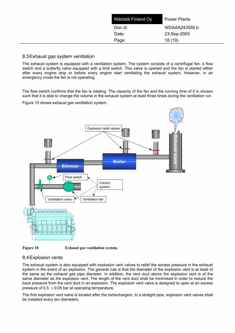
Wärtsilä Finland Oy Power Plants
Doc id: WDAAA243558 b Date: 23-Sep-2003 Page: 18 (19) 8.3 Exhaust gas system ventilation The exhaust system is equipped with a ventilation system. The system consists of a centrifugal fan, a flow switch and a butterfly valve equipped with a limit switch. This valve is opened and the fan is started either after every engine stop or before every engine start ventilating the exhaust system. However, in an emergency mode the fan is not operating.
The flow switch confirms that the fan is rotating. The capacity of the fan and the running time of it is chosen such that it is able to change the volume in the exhaust system at least three times during the ventilation run.
Figure 10 shows exhaust gas ventilation system.
SilencerBoiler
fs
Ventilation fan
Flow switch
Ventilation valve
Exhaust stack
Explosion relief valves
Controlsystem
Figure 10 Exhaust gas ventilation system.
8.4 Explosion vents The exhaust system is also equipped with explosion vent valves to relief the excess pressure in the exhaust system in the event of an explosion. The general rule is that the diameter of the explosion vent is at least of the same as the exhaust gas pipe diameter. In addition, the vent duct above the explosion vent is of the same diameter as the explosion vent. The length of the vent duct shall be minimised in order to reduce the back pressure from the vent duct in an explosion. The explosion vent valve is designed to open at an excess pressure of 0.5 ± 0.05 bar at operating temperature.
The first explosion vent valve is located after the turbochargers. In a straight pipe, explosion vent valves shall be installed every ten diameters.

Wärtsilä Finland Oy Power Plants
Doc id: WDAAA243558 b Date: 23-Sep-2003 Page: 19 (19) The silencer inlet and outlets are also equipped with explosion vents. The explosion vent in the inlet may have been omitted if the distance from the previous explosion vent is less than 5 times the diameter. Only absorption silencers with straight-through design are used. Reactive type silencers with internal chambers are not allowed for lean-burn engines due to their disadvantages during an explosion. Gas may collect in the reactive part in the chambers and thus a violent explosion is possible if unburnt gas is present.
The boiler is equipped with integrated explosion vents at the inlet and outlet of the boiler. The size of these vents is dependent on the boiler design, but should as a minimum be of the same size as the inlet duct to the boiler. If it is impossible to integrate these valves into the boiler, corresponding explosion vents are located in the exhaust gas duct close to inlet and outlet of the boiler.
Explosion vents are ducted outdoors with a duct of at least the same size as the explosion vent. The duct is covered with light-weight noise and weather protection.
The outlet of the duct is located so that personnel are not present during normal operation, and the proximity of the outlet is clearly marked as a hazardous area.
Due to the gas velocities created by a possible explosion, under pressure may be created in the latter parts of the system. Therefore, the stack is dimensioned to sustain an under pressure of 0.3 bar without collapse.
Also, available are active extinguishing systems for explosion prevention, such as explosion suppression. These, however, are not a standard option for lean-burn engine equipped power plants, but have to be considered case by case for special applications. A problem with these is that the actual position of the ignition is not known. Thus the extinguishing system is nearly impossible to design.
Note! After a gas explosion the safety equipment shall be inspected and damaged parts changed for new ones according to manufacturers' instructions. The reason for explosion must be clarified and eliminated before the next start.


t®êíëáä®=cáåä~åÇ=ló= Power Plants
Doc. id: WDAAA247714 a Date: 20-Nov-2003 Page: 1 (7) Status: APPROVED Made/Approved: MKO010 / AEK001 Project: WFI-P Power Plant Technology, IN023 Name: General Subject: Wärtsilä safety manual for lean burn gas engine
TABLE OF CONTENTS (THE WHOLE MANUAL) FOR A POWER PLANT:
1 General WDAAA247714
2 Engine WDAAA247740
3 Power plant WDAAA243558
TABLE OF CONTENTS (THE WHOLE MANUAL) FOR A COMPRESSOR STATION:
1 General WDAAA247714
2 Engine WDAAA247740
3 Compressor station WDAAA299978
TABLE OF CONTENTS (GENERAL)
1 General ...................................................................................................................................... 2 2 Natural gas ................................................................................................................................ 2
2.1 Composition ........................................................................................................................... 2 2.2 Properties............................................................................................................................... 3
3 General health and safety aspects ............................................................................................ 3 3.1 Breathing natural gas ............................................................................................................. 4 3.2 Breathing carbon monoxide ................................................................................................... 4
4 Gas leaks and fires .................................................................................................................... 5 5 Gas explosions .......................................................................................................................... 5
5.1 Prevention of gas explosions and minimising the consequences .......................................... 6

Wärtsilä Finland Oy Power Plants
Doc id: WDAAA247714 a Date: 20-Nov-2003 Page: 2 (7) 1 General
This Wärtsilä® lean-burn gas engine safety manual gives general information on natural gas properties and hazards of using it together with description of safety equipment and measures both on site and on embedded in equipment. The aim of this manual is to make the operating personnel acquainted with the plant and its safety systems. To ensure safe operation of the plant the user must read this manual before operating the plant. As the plant design may vary depending on auxiliary system's design and use of different suppliers, it is necessary to obtain detailed information on the engine and plant components. The user should therefore always read the manuals delivered.
NOTE ! This manual does not include any local laws, regulations or instructions concerning gas safety. Please refer to local documentation and legislation to fulfil them.
In engine part of this manual, the description of the engine operation is given in different stages to give the operator a clear view of how the safety system controls the engine. Refer to engine manual for instructions on normal engine operation. As it is not possible to handle all possible danger situations in this manual, the user should always consider possible error situations with a safety perspective. A gas fire or explosion may result in considerable material damage and, in the worst case, human injury. Therefore, instructions given in this manual must be followed. In addition, any local regulations and laws must be obeyed.
2 Natural gas
Natural gas is a mixture of combustible and inert gases, each with varying physical properties. Many of the fuel gas properties and the gas suitability to be used as a fuel for internal combustion engines can be determined from the component gas properties.
2.1 Composition Composition of the natural gas varies substantially between the various production fields. Gases having composition according to the table below are called natural gases.

Wärtsilä Finland Oy Power Plants
Doc id: WDAAA247714 a Date: 20-Nov-2003 Page: 3 (7) Table 1. Composition of natural gases (by volume).
Methane CH4 70 – 90 % Ethane C2H6 0 – 7 % Propane C3H8 0 – 2 % Butane C4H10 0 – 0.5 % Hydrogen H2 Traces Carbon dioxide CO2 0 – 10 % Oxygen O2 0 – 0.2 % Nitrogen N2 0 – 15 % Hydrogen sulphide H2S 0 – 10 ppm
2.2 Properties Natural gas properties vary slightly according to its composition. Yet, most of its properties are attributed to methane, the main constituent. Natural gas is a combustible, non-odorous, colourless and tasteless gas, and therefore difficult to detect. To make it sensible, it is normally scented with tetra hydro thiophene (THT, C4H8S). Using this additive, natural gas can be detected by smell already at as low concentrations as 0.05 – 0.2 vol.-%. The density of natural gas is around 0.75 – 0.85 g/cm3. Thus, it is lighter than air and tends to rise in closed, draughtless space. Natural gas requires certain concentration to be ignited or burned. At 0 °C the concentration has to be 5 – 15 vol.-%, lower or higher concentrations do not ignite or burn. At higher temperature this area is slightly enlarged and at 500 °C it is 3 – 20 vol.-%. Previous values apply to, if gas is mixed with air. If oxygen only is present instead of air, the limit is 5 – 60 vol.-% at 0 °C. The auto-ignition temperature for natural gas is around 600 °C. At this temperature natural gas will self-ignite and burn independent of concentration as long as any oxygen is present. Complete burning of natural gas yields carbon dioxide (CO2) and water (H2O). If there is not enough air, carbon monoxide (CO) will build up.
3 General health and safety aspects
Dangerous situations with natural gas are caused by gas leakage and its consequences. These include gas fires and explosions as well as ihnalation of natural gas or carbon monoxide, which forms in cases where natural gas is burning without a sufficient oxygen supply.

Wärtsilä Finland Oy Power Plants
Doc id: WDAAA247714 a Date: 20-Nov-2003 Page: 4 (7) 3.1 Breathing natural gas Natural gas in itself is not poisonous. With high concentrations it displaces air and may therefore cause suffocation. Inhaling small amounts and concentrations of natural gas does not pose any danger. Higher concentrations will cause sleepiness, headache and drowsiness. In even higher concentrations, it causes suffocation.
kç=ëóãéíçãë
päÉÉéáåÉëëI=ÜÉ~Ç~ÅÜÉIå~ìëÉ~I=ÇáòòáåÉëë
pìÑÑçÅ~íáçåa~åÖÉêçìë=ä~Åâ=çÑ=çñóÖÉå
MB
NMB
OMB
PMB
d~ë=ÅçåÅ
Éåíê~íáçå=Äó=îç
äìãÉ
Figure 1. Symptoms of natural gas inhalation.
Normally natural gas has been odorised to facilitate its detection in case of leak. The odorant has a repulsive smell and it can be detected readily when the concentration of the gas is well below the ignition limit. However, there is no way to tell the concentration by the smell. First aid for natural gas exposure depends on the symptoms. Slight breathing difficulties normally disappear when moving the person to fresh air. Serious breathing difficulties or unconsciousness will call for revival actions and medical attention.
3.2 Breathing carbon monoxide Generally, most of the deaths associated with natural gas accidents are caused by carbon monoxide, CO. Carbon monoxide is a gas which is formed when natural gas is burning without sufficient amount of oxygen (incomplete burning). Carbon monoxide often forms during gas fires. Carbon monoxide is highly poisonous, odourless and tasteless gas, which is slightly lighter than air. Relative density is 0.967. This makes it a very dangerous gas: It is very difficult to observe without proper measurement equipment and it tends to be at the level of relief. Carbon monoxide’s poisonous effect is based on that it very effectively replaces oxygen in blood circulation. Carbon monoxide quickly binds with haemoglobin with an affinity 200 to 250 times greater than that of oxygen to form COHb. This happens already in very low concentrations and severe symptoms are quickly developed. The first symptom of carbon monoxide poisoning is a cheerful, happy feeling and headache. At this point, it is very important to realise the symptoms and leave the area immediately.
Wärtsilä Finland Oy Power Plants
Doc id: WDAAA247714 a Date: 20-Nov-2003 Page: 5 (7) If the exposure to carbon monoxide continues, the person will soon loose his ability to control his/her muscles, effectively paralysing him/her and soon followed by unconsciousness. At this point, the person will need aid to get out from the area. Further exposure quickly leads to death. First aid for symptoms, like breathing difficulties and headache, caused by carbon monoxide is moving the patient to fresh air. Unconsciousness requires proper revival actions and immediate medical attention.
4 Gas leaks and fires
A gas leak into a building may lead to a gas fire and explosion. Therefore, it is important to prevent any leaks by examining regularly and carefully the gas system for leakage. This should be done using a leak detection liquid and/or a gas detector. If any of the connections in the gas system is opened, new sealing should be used when reassembling. The following safety instructions should be distributed to all personnel working at the Lean burn gas engine power plant, to ensure that proper and safe counter measures are taken in case of a gas leak or fire. The instructions should also be posted in a visible place in the plant. In case of fire or gas leak: • Close the main gas valve (or any valve upstream the fire). This will stop the gas leak and
eventually extinguish the gas fire. In case of fire, do NOT close valves on both sides of a pipe caught in the fire. This would cause the pressure to rise and eventually the pipe to explode. If the gas supply system contains a gas compressor, press the gas compressor emergency button to close down and ventilate the compressor.
• Do NOT put out a gas fire with water or fire extinguisher. A gas fire should be put out EXCLUSIVELY by shutting off the gas supply. If a gas fire is extinguished by other means, a gas explosion may occur when the out flowing gas makes contact with hot residues.
• Evacuate the affected area. Evacuate people from fire or gas explosion risk areas. • Arrange proper ventilation. Open doors and windows, avoid using electrical switches and
equipment, do not smoke. Natural gas in high concentration has a slight narcotic effect that disappears when breathing fresh air. Carbon monoxide possibly created in a fire is highly poisonous, causes first dizziness and headache then quickly paralyses, and leads to death. If a person is suspected to have inhaled carbon monoxide, bring him out into fresh air and call for medical attention immediately.
• Call local emergency number. Inform authorities of the fire or gas leak so that proper measures may be taken.
All Lean burn gas engine power plants provided by Wärtsilä are equipped with suitable detection and alarm system for gas leaks and fire.
5 Gas explosions
It is necessary to realise that gas is not explosive by it self, but some preconditions must be fulfilled before an explosion can occur. There are three main preconditions to fulfil: • adequate gas air relation • sufficient mixing • ignition source

Wärtsilä Finland Oy Power Plants
Doc id: WDAAA247714 a Date: 20-Nov-2003 Page: 6 (7) Gas explosion is a quick chemical reaction between gas and oxygen, that is the gas is burning rapidly. Contrary to explosives, natural gas does not consist of any chemically bound oxygen. Thus, additional oxygen (air) is necessary for a gas explosion to take place. Explosion only takes place with certain proportions of gas and air (for natural gas typically 5...15 vol.-% gas in air). A too lean mixture and a too rich mixture will not ignite. Gas and oxygen (air) must be sufficiently mixed, too. Mixing ensures that each gas molecule has oxygen molecules in close range to react with. The gas explosion itself tends to mix the yet unburned gas and air due to turbulence, thus further assisting the propagation. Finally there must be an ignition source. This may be any particle with high enough energy (temperature) to start the reaction. After the reaction has started, it will produce enough energy (heat) to continue by itself until all gas has reacted or circumstances otherwise turned unfavourable to explosion. To get an idea what is happening during an explosion, a basic situation can be examined. An explosion can be thought to start in a situation where gas and oxygen are mixed in a long container, open at one end, and the mixture is motionless. An ignition source ignites the gas oxygen mixture at the closed end and the reaction starts. The reaction starts with a slow burning and a flame propagation velocity in order of 5 m/s. Increasing pressure and turbulence cause the flame propagation velocity to increase to detonation. At this point the velocity may reach 2000 m/s. The reaction continues until either of the reactants have run out or circumstances otherwise turn unfavourable to explosion propagation. The explosion causes a pressure wave at the propagation front. This high local pressure may damage structures. Behind the explosion front the reacted gases cool down quite rapidly and, together with mass inertia of the high velocity gas, may cause a negative pressure especially in long piping. This negative pressure may also cause damage to equipment. If a gas explosion for some reason happens all systems affected by the explosion must be thoroughly inspected both mechanically and functionally. All damaged parts must be repaired or changed for new ones. Safety equipment and system must be inspected with special care and if necessary new components must be installed. Refer to manufacturers' instructions. Before the next start the reason for explosion must be clarified and eliminated.
5.1 Prevention of gas explosions and minimising the consequences It is of utmost importance, that plant staff realises the risks associated with all gas applications and minimises these by careful working practices and consideration. In preventing gas explosions at the plant or in the engine, the most important thing is to prevent the gas from reaching the explosive concentration. It is the only way to avoid gas explosions completely. If a gas explosion occurs, it is important to protect people, equipment and environment from damage. Damage is caused by shock wave and burning effect of the expanding and partly burning gases. Damage can be avoided by preventing pressure build up in equipment and guiding the released pressure to an open area.
Wärtsilä Finland Oy Power Plants
Doc id: WDAAA247714 a Date: 20-Nov-2003 Page: 7 (7) Wärtsilä® Lean burn gas engine power plants and compressor stations are equipped with high quality safety system to prevent gas explosions. All reasonable measures have been employed to prevent gas build-up, ignition and explosion. With proper and careful working practices and regular inspections, the plant is a safe place to work. In a Lean burn gas engine power plant and a compressor station, the most probable place for gas explosion is in the exhaust system. Unburned gas may escape into exhaust system in an engine malfunction. Engine safety system aims to prevent this from happening. The pressure build up in exhaust system is minimised by using explosion vents. Vent size, number and position must be carefully considered and selected during the design stage in order to get a safe and properly functioning system. See chapter “exhaust gas system”.

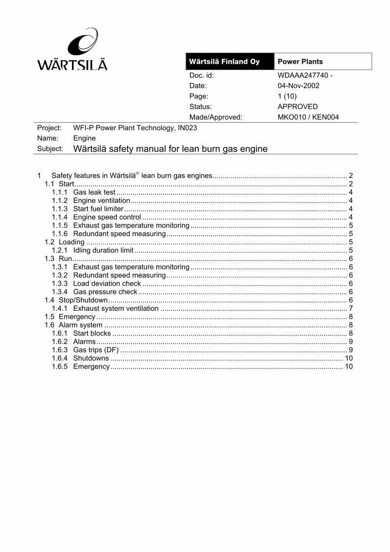
t®êíëáä®=cáåä~åÇ=ló= Power Plants
Doc. id: WDAAA247740 - Date: 04-Nov-2002 Page: 1 (10) Status: APPROVED Made/Approved: MKO010 / KEN004 Project: WFI-P Power Plant Technology, IN023 Name: Engine Subject: Wärtsilä safety manual for lean burn gas engine 1 Safety features in Wärtsilä lean burn gas engines................................................................... 2
1.1 Start........................................................................................................................................ 2 1.1.1 Gas leak test ................................................................................................................... 4 1.1.2 Engine ventilation............................................................................................................ 4 1.1.3 Start fuel limiter ............................................................................................................... 4 1.1.4 Engine speed control ...................................................................................................... 4 1.1.5 Exhaust gas temperature monitoring .............................................................................. 5 1.1.6 Redundant speed measuring.......................................................................................... 5
1.2 Loading .................................................................................................................................. 5 1.2.1 Idling duration limit .......................................................................................................... 5
1.3 Run......................................................................................................................................... 6 1.3.1 Exhaust gas temperature monitoring .............................................................................. 6 1.3.2 Redundant speed measuring.......................................................................................... 6 1.3.3 Load deviation check ...................................................................................................... 6 1.3.4 Gas pressure check ........................................................................................................ 6
1.4 Stop/Shutdown....................................................................................................................... 6 1.4.1 Exhaust system ventilation ............................................................................................. 7
1.5 Emergency ............................................................................................................................. 8 1.6 Alarm system ......................................................................................................................... 8
1.6.1 Start blocks ..................................................................................................................... 8 1.6.2 Alarms............................................................................................................................. 9 1.6.3 Gas trips (DF) ................................................................................................................. 9 1.6.4 Shutdowns .................................................................................................................... 10 1.6.5 Emergency.................................................................................................................... 10

Wärtsilä Finland Oy Power Plants
Doc id: WDAAA247740 - Date: 04-Nov-2002 Page: 2 (10) 1 Safety features in Wärtsilä lean burn gas engines
Wärtsilä lean burn engines have built-in safety features to ensure the safest possible operation. The aim is to avoid any operating situations where gas could pose a danger and, if such occasions occur, to ensure a safe handling of the situation. In the following chapters, the different safety features are described based on the operating phase. It is expected that the reader is familiar with the engine and its operation.
1.1 Start Before starting the engine, possible maintenance and service operations must have been completed and all persons should have left the risk areas. Normal duties preceding the start (refer to engine manual section 3 "Start, Stop, Operation") should be carried out and the gas regulating unit be prepared for use.
Engine start can only be attempted when engine is stopped and ready for start. Several start blocks must be cleared before the engine is ready for start. For detailed list of start blocks, see engine manual section 23.7 "Alarm and safety system".
The purpose of the start blocks is to prevent the engine from being started before it is safe to do so. The blocks concerning the safety are:
• Exhaust system ventilation. Exhaust system is ventilated when the engine has stopped due to a stop signal or if a shutdown or emergency stop has occurred. An option is to ventilate the exhaust gas system in the start sequence before engine start.
• This is made to ensure that possible gas in the exhaust system is discharged. For more details, see chapter “exhaust gas system”
• Tripped safety valve in the gas regulating unit. There is a safety valve in the gas regulating unit. If it has been tripped, the engine can not be started.
• Low or high gas supply pressure at gas regulating unit. Gas pressure must be within limits to start the engine. Too high or too low gas pressure may lead to incorrect air fuel mixture or gas admission valve malfunction. In both cases the proper ignition can not be guaranteed and the start is prohibited.
• Low or high gas supply temperature at gas regulating unit. Gas temperature affects the gas density. If the temperature is not within the limits, the amount of gas admitted to cylinder may be wrong and consequently the mixture may not ignite, thus the start is blocked.
After all start blocks have been cleared and a start command is accepted, start order is given from operator interface (WOIS, Wärtsilä Operator Interface System) either automatically (timer or other plant control request) or manually by clicking the "Start" button. In both cases the following tasks are performed automatically:
• A gas leak test.
• The control air system is activated.
• Engine is started according to Table 1, depending on engine type.

Wärtsilä Finland Oy Power Plants
Doc id: WDAAA247740 - Date: 04-Nov-2002 Page: 3 (10) Table 1. Engine events during start sequence
Rpm SG engine DF engine
0 − Starter motors/start air valves are engaged
− Waste gate closed
− Starter motors engaged
− Main diesel fuel ramp to stop position
X − Ventilation turns completed − Ventilation turns completed
50 − Ignition started
− Pre combustion chamber gas injection started
− Main combustion chamber gas injection started
− Pilot fuel injection started
135 − Starting motors/start air valves disengaged
− Waste gate taken into operation
140 − Starting motors disengaged
175 − Engine to RUN-mode control
− Main combustion chamber gas injection from start fuel limiter to PID control
− Engine to RUN-mode control
350 − Main diesel fuel ramp released from stop position
− Engine ready for gas operation
− Cylinder boost (pilot fuel injection) on
730 − Exhaust gas temperature balancing started
− Cylinder boost on
− Ignition map to use
− Cylinder boost (main gas injection) on
− Exhaust gas temperature balancing started
Start sequence (SG) is graphically presented in Figure 1. Detailed descriptions of all the safety features are in the following sections.
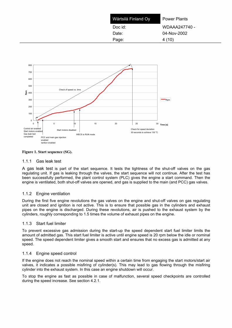
Wärtsilä Finland Oy Power Plants
Doc id: WDAAA247740 - Date: 04-Nov-2002 Page: 4 (10)
0
100
200
300
400
500
600
700
800
0 5 10 15 20 25 30 Time [s]
Rpm
Rpm
Control air enabledStart motors enabledGas leak test completed PCC and main gas injection
enabledIgnition enabled
Start motors disabled
WECS is RUN mode
Check for speed deviation30 seconds to achieve 130 oC
Check of speed vs. time
Figure 1. Start sequence (SG).
1.1.1 Gas leak test
A gas leak test is part of the start sequence. It tests the tightness of the shut-off valves on the gas regulating unit. If gas is leaking through the valves, the start sequence will not continue. After the test has been successfully performed, the plant control system (PLC) gives the engine a start command. Then the engine is ventilated, both shut-off valves are opened, and gas is supplied to the main (and PCC) gas valves.
1.1.2 Engine ventilation During the first five engine revolutions the gas valves on the engine and shut-off valves on gas regulating unit are closed and ignition is not active. This is to ensure that possible gas in the cylinders and exhaust pipes on the engine is discharged. During these revolutions, air is pushed to the exhaust system by the cylinders, roughly corresponding to 1.5 times the volume of exhaust pipes on the engine.
1.1.3 Start fuel limiter To prevent excessive gas admission during the start-up the speed dependent start fuel limiter limits the amount of admitted gas. This start fuel limiter is active until engine speed is 20 rpm below the idle or nominal speed. The speed dependent limiter gives a smooth start and ensures that no excess gas is admitted at any speed.
1.1.4 Engine speed control If the engine does not reach the nominal speed within a certain time from engaging the start motors/start air valves, it indicates a possible misfiring of cylinder(s). This may lead to gas flowing through the misfiring cylinder into the exhaust system. In this case an engine shutdown will occur.
To stop the engine as fast as possible in case of malfunction, several speed checkpoints are controlled during the speed increase. See section 4.2.1.

Wärtsilä Finland Oy Power Plants
Doc id: WDAAA247740 - Date: 04-Nov-2002 Page: 5 (10) 1.1.5 Exhaust gas temperature monitoring After the start the exhaust gas temperature in each cylinder should rise quite rapidly to the normal value (depending on the engine load). If the temperature is low, it also indicates possible misfiring of cylinder(s). If a specified minimum exhaust gas temperature for any cylinder is not reached in a specified time after idle or nominal speed is reached, the main gas duration for that cylinder will be immediately increased. If the cylinder still is under the specified minimum exhaust gas temperature after a specified time, the engine will be shut down.
Together with the engine speed control this limits the running time of the engine to minimum in the event of any cylinders not firing.
1.1.6 Redundant speed measuring Engine speed is measured with a redundant system. It consists of a rotary encoder on the camshaft and a back-up speed pick-up on the flywheel or separate speed pick-ups on flywheel and camshaft. The speed signal is used to determine the timing and duration of the gas admission and ignition. Fault in this system may lead to the wrong gas admission- and ignition timing and possibility to unburned gas escaping into the exhaust system.
During one camshaft revolution, the encoder/speed pick-up sends a certain number of pulses and one marker pulse at A1 cylinder TDC. Pulses are calculated and if their number deviates more than a specified number from nominal, emergency mode will be activated.
WECS calculates the speed from the signal in several different units. The calculated speed signals are cross-checked and any deviations will cause a shutdown. This feature is active after the engine has entered the run mode.
NOTE ! To avoid possible accidents, it is not recommended to stay in the engine room and boiler/silencer room during an engine start and no-load running.
NOTE ! A prolonged or repeated start attempt may lead to gas being discharged to exhaust system and as a consequence a gas explosion.
If it becomes obvious during the start, that engine will not start normally and the safety system is not responding, the user should immediately interrupt the start attempt by giving the engine a stop order on the operator interface or by pushing any of the emergency buttons.
1.2 Loading
1.2.1 Idling duration limit
After the engine has been successfully started and the nominal speed has been reached the engine is ready for loading. The combustion at no load or at low load is incomplete due to low cylinder pressure and low combustion temperature. Therefore, unburned gas is fed into the exhaust system. It is also more difficult to detect abnormalities (misfiring) when the combustion is poor.
Running time is limited in the unloaded condition, where combustion efficiency is low. If the loading does not occur during this time engine shutdown will occur.
A minimum load (approximately 10 % of the maximum load) is immediately applied in base load operation plants to stabilise the combustion and to avoid reverse power.

Wärtsilä Finland Oy Power Plants
Doc id: WDAAA247740 - Date: 04-Nov-2002 Page: 6 (10) 1.3 Run
1.3.1 Exhaust gas temperature monitoring During the engine operation, the system monitors the exhaust gas temperature of each cylinder. This is to ensure that all cylinders are ignited and combusting correctly.
If the temperature of any cylinder is lower than or higher than the specified limit, a shutdown occurs. In addition, if the temperature deviates more than a specified value from the exhaust gas average temperature, a shutdown occurs.
The average gas temperature is also monitored and compared to a reference value in the engine control program. Deviation from the reference value indicates deviation in the air fuel ratio and engine load is reduced.
1.3.2 Redundant speed measuring Redundant speed measuring is always active during engine operation. See chapter 1.1.6.
1.3.3 Load deviation check If the actual load deviates too much from set load, while running against the grid, the engine will be shut down.
1.3.4 Gas pressure check Gas pressure is monitored during the run to ensure proper gas supply and air fuel ratio. If the gas pressure is too low or too high compared to charge air pressure, the engine is shut down. Too high gas pressure may prevent the gas valves from functioning and too low gas pressure may cause too lean fuel mixture.
1.4 Stop/Shutdown Stop and shutdown procedures are equal regarding the engine functions. The difference between these two is in the initiation. Stop is initiated by the operator or PLC. Shutdown is initiated by engine control system (WECS) or by PLC and is caused by some parameter or measured value exceeding shutdown limit. In both cases the actual procedure is the same but varies between engine types.
When the stop request is activated, the PLC first unloads the engine and then shuts off the gas supply from gas regulating unit to the engine. The PLC then tells the WECS to shut down the engine.
In case of engine initiated shutdown, the PLC shuts off the gas supply to engine immediately after WECS signal. Note that the engine is not unloaded in this case. In both cases the engine sequence is as follows varying by engine type:

Wärtsilä Finland Oy Power Plants
Doc id: WDAAA247740 - Date: 04-Nov-2002 Page: 7 (10) Table 2. Engine stop and shut-downs sequence.
Rpm SG engine DF engine 720 Main combustion chamber
gas injection is cut off. Stop command is sent to PLC if engine activated shutdown.
Main diesel fuel ramp is taken to stop position. Stop command is sent to PLC if engine activated shutdown.
500 Pre combustion chamber gas injection is cut off. Ignition is cut off.
Pilot fuel pump is shut down. Main gas injection is cut off.
50 Pilot fuel injection is cut off. 0 Engine condition is checked. Engine condition is checked.
After the engine has stopped the exhaust system is ventilated to discharge any unburned gas. If the stop has been caused by an alarm, the engine will not be ready for start before the reason has been cleared and alarm has been reset.
Stop sequence (SG) is graphically presented in Figure 2.
0
100
200
300
400
500
600
700
800
0 10 20 30 40 50 60 Time [s]
Rpm
Rpm
Gas pressure = 0when rpm = 500
Stop command and the gas regulating unit closes the supply
Gas admission valves deactivated
Ignition system disabledEngine ventilation turns
Figure 2. Stop sequence (SG).
1.4.1 Exhaust system ventilation When the engine has been stopped the exhaust system is ventilated. It also acts as a start block. See chapter “exhaust gas system”.

Wärtsilä Finland Oy Power Plants
Doc id: WDAAA247740 - Date: 04-Nov-2002 Page: 8 (10) 1.5 Emergency Emergency mode is initiated either manually by the operator or automatically by the control system in case of critical fault on the engine or auxiliary equipment. In emergency mode the gas supply to the engine is shut off and all engine controls (ignition, gas injection, pilot fuel injection etc.) are disabled immediately.
NOTE ! After an emergency the reason must be clarified.
When the operator has reset the emergency indications the engine is ready for a new start if no start blocks are active.
Emergency sequence is graphically presented in Figure 3.
0
100
200
300
400
500
600
700
800
0 10 20 30 40 50 60 Time [s]
Rpm
Rpm
Gas pressure = 0when rpm = 500Emergency stop order:
- gas regulating unit closes the gas supply- gas admission valves closed- ignition disabled
Engine ventilation turns
Figure 3. Emergency sequence.
1.6 Alarm system
1.6.1 Start blocks Before the PLC activates a start request the engine must be ready for start. The following is a list of the start blocks concerning gas safety:
• Shutdown or emergency signal not reset.
• Exhaust system ventilation not finished.
• Start air pressure below the start block limit. If the start air pressure is too low, the start will be unreliable.
• Main (and pre combustion chamber) combustion chamber gas pressure below start block limit after the start signal.
• Low or high gas temperature.
• Safety valve in the gas regulating unit is tripped.

Wärtsilä Finland Oy Power Plants
Doc id: WDAAA247740 - Date: 04-Nov-2002 Page: 9 (10) Refer to engine manual, section 23.7.1 for detailed list of start blocks.
1.6.2 Alarms Following is a list of the alarms concerning gas safety:
• Sensor failure. All sensors connected to WECS are monitored. If the signal level or value is abnormal (out of range) an alarm will be initiated. Sensors with digital signals are wired so that they normally give a high (NC) signal to a measuring unit. If a wire breaks, it will initiate an alarm. Some sensors of vital importance to the engine performance or safety will activate a shutdown request. All other sensor failures cause an alarm. See engine manual for further information.
• Gas pressure deviation. The actual gas pressure is compared with the charge air pressure. If the gas pressure is less than a pre-set level over the charge air pressure, an alarm is activated. Low pressure will lead to too lean mixture, misfiring and thus, gas discharging into exhaust system.
• Low control air pressure. If the control air pressure is too low, it will lead to malfunction of the exhaust waste gate valve. This in turn leads to uncontrolled gas air mixture. Load is reduced 25% to avoid this.
• High exhaust gas temperature after any cylinder. High exhaust gas temperature indicates too rich gas air mixture, which may lead to knocking.
• High exhaust gas temperature deviation between cylinders. This may indicate that part of the cylinders are not firing, or that part of the cylinders have too rich fuel air mixture. In both cases gas may be discharged into exhaust system.
• Start attempt failed
Alarms can only be reset by the operator. They will not be reset automatically if engine conditions return to normal.
Refer to engine manual, section 23.7.2 for detailed list of alarms.
1.6.3 Gas trips (DF) In addition to normal alarms and shutdowns, the DF engine can be tripped from gas operation to diesel operation in case of problem. Reasons to trip the engine are following:
• Charge air pressure sensor failure, which may cause incorrect A/F-ratio and misfiring.
• Heavy knocking, may indicate too much gas being admitted to cylinder
• Pilot fuel pressure sensor failure may cause misfiring due to incorrect pilot fuel pressure
• Low/high pilot fuel pressure may cause misfiring
• Gas pressure build up time elapsed. Gas pressure has not risen to correct value within time limit.
• Gas pressure deviation. May lead to misfiring due to incorrect A/F-ratio.
• High load swing. May indicate gas valve malfunction.
• Exhaust gas temperature deviation. May indicate improper A/F-ratio
• Low exhaust gas temperature from pilot fuel injection. Not enough pilot fuel is being injected to cylinder.
• MFI duration max time. Gas admission not working properly as the maximum duration is not enough.
• Max idle time. As with SG engine

Wärtsilä Finland Oy Power Plants
Doc id: WDAAA247740 - Date: 04-Nov-2002 Page: 10 (10) 1.6.4 Shutdowns There are a number of reasons for a shutdown of the engine. The shutdown is generated in the WECS because of a shutdown request. The status of the shutdowns is sent to the PLC. Following is a list of the shutdown requests concerning gas safety:
• Start failure.
• High charge air temperature
• High exhaust gas temperature after any cylinder
• Low exhaust gas temperature after any cylinder
• High exhaust gas temperature deviation between cylinders
• High deviation of gas pressure
Refer to engine manual, section 23.7.3 for detailed list of shutdowns.
1.6.5 Emergency There are a number of reasons for an emergency of the engine. The emergency is generated in the WECS because of an emergency request. Below is a list of emergency requests concerning gas safety:
• Emergency push button, on engine or external, pressed
• Rotary encoder /speed sensor failure
• Over speed from rotary encoder
• Over speed from speed pick-up
• Speed deviation between rotary encoder and engine speed pick-up
• Number of encoder pulses per revolution deviate more than allowed from nominal value.
• Degassing failure in auto stop mode. Activated if the gas pressure is still present after the shutdown control task has disabled the inlet gas pressure control.
Refer to engine manual section 23.7.4 for detailed list of emergency.
Operating troubles and troubleshooting concerning the gas components and control system are described in the engine manual, section 8 "Operating Troubles, Emergency Operation".
t®êíëáä®=cáåä~åÇ=ló= Power Plants
Doc. id: WDAAA299978 - Date: 05-Nov-2003 Page: 1 (19) Status: APPROVED Made/Approved: MKO010 / AEK001 Project: WFI-P Power Plant Technology, IN023 Name: Compressor station Subject: Wärtsilä safety manual for lean burn gas engine 1 General ...................................................................................................................................... 2 2 Hazardous area classification.................................................................................................... 2
2.1 Classification for engine ......................................................................................................... 2 2.1.1 American Codes ............................................................................................................. 2 2.1.2 European Codes ............................................................................................................. 2 2.1.3 UK Codes........................................................................................................................ 2
2.2 Classification for auxiliary system .......................................................................................... 3 3 Control philosophy ..................................................................................................................... 4
3.1 Start........................................................................................................................................ 4 3.2 Run......................................................................................................................................... 4 3.3 Stop........................................................................................................................................ 4 3.4 Shut down .............................................................................................................................. 4 3.5 Emergency ............................................................................................................................. 5 3.6 Stand-by................................................................................................................................. 6
4 Fire fighting and gas detection system ...................................................................................... 6 4.1 Fire detectors ......................................................................................................................... 6 4.2 Fire fighting equipment........................................................................................................... 7 4.3 Gas detectors......................................................................................................................... 7 4.4 Alarm and shut down system description............................................................................... 7
5 Engine room ventilation ............................................................................................................. 7 6 Emergency lighting .................................................................................................................... 8 7 Gas supply system .................................................................................................................... 8
7.1 Main shut off valve.............................................................................................................. 9 7.2 Fuel gas regulating unit ...................................................................................................... 9
7.2.1 Design............................................................................................................................. 9 7.2.2 Function ........................................................................................................................ 12
7.2.2.1 Normal stop or shut down...................................................................................... 14 7.2.2.2 Emergency............................................................................................................. 14 7.2.2.3 Plant emergency.................................................................................................... 14
7.2.3 Operation of the fuel gas regulating unit ....................................................................... 15 7.2.3.1 Activation of the fuel gas regulating unit ................................................................ 15 7.2.3.2 Monitoring of the fuel gas regulating unit ............................................................... 15 7.2.3.3 Shutting down the fuel gas regulating unit for maintenance .................................. 16 7.2.3.4 Emergency stop of the fuel gas regulating unit...................................................... 17
8 Exhaust gas system................................................................................................................. 17 8.1 General ................................................................................................................................ 17 8.2 Piping design........................................................................................................................ 17 8.3 Exhaust gas system ventilation............................................................................................ 18 8.4 Explosion vents .................................................................................................................... 18

Wärtsilä Finland Oy Power Plants
Doc id: WDAAA299978 - Date: 05-Nov-2003 Page: 2 (19) 1 General
This section of manual describes mainly the safety features of auxiliary components i.e. outside engine in the compressor station.
2 Hazardous area classification
2.1 Classification for engine In the case of an adequately ventilated enclosure containing gas-fuelled engines it need not be classified solely by reason of the engine fuel. This is the case with a normal power plant installation.
In the case of a gas compressor driven by a gas engine, the engine is seen as an ignition source and the gas compressor is a source of possible gas leak. The possibility of a gas leak is considered to be higher in a gas compressor, thus, a gas engine driven compressor is classified as hazardous area, normally zone 2 or class I division 2.
In special designs (see paragraph 2.2) the hazardous area can be limited to a compressor room provided that the fuel gas do not enter to engine room. In this case engine is not classified.
The above mentioned statement is based on the following standards:
2.1.1 American Codes American Petroleum Institute
API 500: Recommended Practice for Classification of Locations for Electrical Installations at Petroleum Facilities Classified as Class I, Division 1 and Division 2
• Section 8.2.5 Hydrocarbon-fuelled Prime Movers
National Fire Protection Association
NFPA 37: Standard for Stationary Combustion Engines and Gas Turbines
NFPA 850: Recommended Practice for Fire Protection for Electric Generating Plants and High Voltage Direct Current Converter Stations
2.1.2 European Codes
EN-60079-10 Electrical apparatus for explosive gas atmospheres; part 10 Classification of hazardous
areas
EN-1834-1 Reciprocating internal combustion engines – Safety requirements for design and construction of engines for use in potentially explosive atmospheres – Part II engines for use in flammable gas and vapour atmospheres.
There are no current EU guidelines for gas engine power generation installations; in such a case Internationally recognised codes are accepted.
2.1.3 UK Codes The Institute of Petroleum
IP15 Area classification code of practice for petroleum installations, Model code of safe practice: part 15
Section 8.7 Combustion Engines

Wärtsilä Finland Oy Power Plants
Doc id: WDAAA299978 - Date: 05-Nov-2003 Page: 3 (19) The Institution of Gas Engineers
IGE/UP/3 Gas fuelled spark ignition and dual fuel engines
Section 8.1.7 Electrical Equipment and Supplies
2.2 Classification for auxiliary system The codes to be followed are EN60079-10, API500 and IGE/SR/25.
In case a gas compressor is separated with a wall from the space in which engine is located, then the engine room is not classified as hazardous area. On the contrary, zones are existing but are limited to small spaces. Zone 2 according to EN60079-10 or class I division 2 according to API500 is found in the gas piping flange joints in fuel gas regulating unit and flow metering unit (option). The hazardous area around the flange is a sphere whose radius is typically 1 m. In addition, vent piping creates a hazardous area near the roof. Radius should be checked for each installation, and is affected by the gas pressure and level of ventilation.
Figure 1 shows a typical example of hazardous area classification for gas engine power plant.
Figure 1 Example of hazardous area classification for a gas engine power plant according to API500.

Wärtsilä Finland Oy Power Plants
Doc id: WDAAA299978 - Date: 05-Nov-2003 Page: 4 (19) In case a gas compressor is in the same space than the engine, the whole space is classified as Zone 2 or class I division 2.
3 Control philosophy
There are different control modes for the power plant. These are:
• Start
• Run
• Stop
• Shut down
• Emergency
• Stand-by
These are discussed briefly below. In addition, different causes for stop, shut down and emergency from power plant as well as different consequences regarding power plant safety are discussed below.
3.1 Start In start mode certain checks are gone through in order to ensure a safe start. The plant control system (PLC) checks for start blocks before engine is allowed to start. After the engine is started following the start sequence the engine mode is changed to running.
3.2 Run In run mode engine output is maintained at the level required by the plant and all engine parameters are monitored and controlled to ensure a safe and reliable operation.
3.3 Stop Stop is activated from WOIS giving an order for engine to stop or it can be done by pressing the stop button in M1 panel. The engine is unloaded and when the load has reached a set value, a stop command for WECS is given.
The fuel gas regulating unit is closed. See chapter fuel gas regulating unit for more details.
3.4 Shut down Shut down is otherwise the same as the stop mode except that it is initiated by a failure detected by WECS or PLC.
Causes for shut down are:
• start sequence failure
• fuel gas system abnormal
• electrical system fault
• safety relay trip

Wärtsilä Finland Oy Power Plants
Doc id: WDAAA299978 - Date: 05-Nov-2003 Page: 5 (19) • WECS shut down signal
• WECS communication failure
• Project specific trip
This includes also shut down command for the fuel gas compressor and the related valves. These valves will be set to default according to project specific documents e.g. with the help of risk assessments.
Main consequences for shut down are:
• Stop command for WECS is given
• Fuel gas regulating unit is closed
3.5 Emergency
Emergency mode is initiated by a hardwired signal. Emergency mode for compressor station is shown in Figure 2.
Emergency can be initiated either by pressing emergency stop push buttons in:
• common panel, which means a plant emergency mode is initiated and all the engines are shut down or
• by engine wise panels, which means an emergency mode is initiated for that engine only
or
by a fire or gas detector.
CFA = common control panelSR
CFC1 CFC2 CFC3
WECS WECS WECS
SR SR SR
Figure 2 A schematic diagram for emergency mode of control system.
SR = safety relay (or safety PLC)
CFC = engine wise control panel
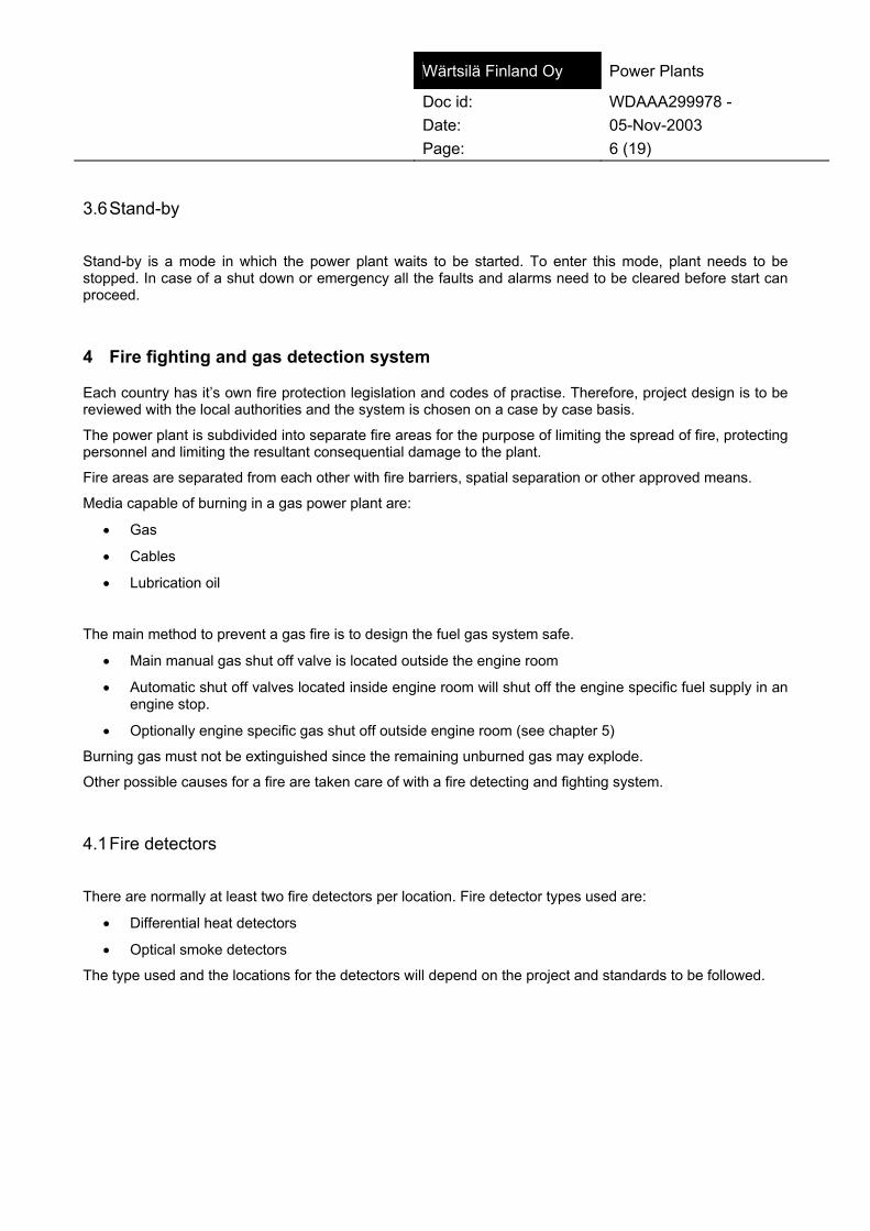
Wärtsilä Finland Oy Power Plants
Doc id: WDAAA299978 - Date: 05-Nov-2003 Page: 6 (19) 3.6 Stand-by
Stand-by is a mode in which the power plant waits to be started. To enter this mode, plant needs to be stopped. In case of a shut down or emergency all the faults and alarms need to be cleared before start can proceed.
4 Fire fighting and gas detection system
Each country has it’s own fire protection legislation and codes of practise. Therefore, project design is to be reviewed with the local authorities and the system is chosen on a case by case basis.
The power plant is subdivided into separate fire areas for the purpose of limiting the spread of fire, protecting personnel and limiting the resultant consequential damage to the plant.
Fire areas are separated from each other with fire barriers, spatial separation or other approved means.
Media capable of burning in a gas power plant are:
• Gas
• Cables
• Lubrication oil
The main method to prevent a gas fire is to design the fuel gas system safe.
• Main manual gas shut off valve is located outside the engine room
• Automatic shut off valves located inside engine room will shut off the engine specific fuel supply in an engine stop.
• Optionally engine specific gas shut off outside engine room (see chapter 5)
Burning gas must not be extinguished since the remaining unburned gas may explode.
Other possible causes for a fire are taken care of with a fire detecting and fighting system.
4.1 Fire detectors
There are normally at least two fire detectors per location. Fire detector types used are:
• Differential heat detectors
• Optical smoke detectors
The type used and the locations for the detectors will depend on the project and standards to be followed.

Wärtsilä Finland Oy Power Plants
Doc id: WDAAA299978 - Date: 05-Nov-2003 Page: 7 (19) 4.2 Fire fighting equipment
Fire fighting system consists of:
• Portable dry powder and/or CO2 extinguishers
• Fire hydrants for fire hoses
• Loose fire hose equipment to be connected to fire hydrants
• Permanently connected fire hose reels
4.3 Gas detectors The gas detectors are required to detect any gas leak. These are located in a position where a gas leak is most likely to occur and be detected. See Figure 1. These are normally:
• Above fuel gas regulating unit
• At ventilation air outlet at the roof level
4.4 Alarm and shut down system description The gas and fire detection system has a control unit, which receives information from detectors placed in critical locations. If a detector is activated, a fire or a gas leak alarm is given locally and/or remotely, to ensure evacuation of personnel and to initial emergency procedures.
An alarm is given when a gas detector is sensing 10 % of LEL (lower explosion limit).
When a gas detector is sensing 20 % of LEL or above, normally an automatic emergency is initiated for the plant shutting down the gas supply at the engine specific fuel gas regulating units and closing the main shut of valve outside the engine room or engine cell. In case of a fire alarm a plant shut down is initiated, as well.
Gas detectors can also be of the type with one level alarm. In this case exceeding an alarm level of 20 % of LEL an emergency mode is initiated.
An option is that the gas detector or fire detector gives an alarm and the necessary actions are taken by operating personnel.
5 Engine room ventilation
The engine room ventilation system is required in order to supply sufficient combustion air to the engine and to maintain the temperature in the engine room at a suitable level.
Ventilation can be classified as inadequate or adequate. The prerequisite for an engine room to be unclassified area regarding explosion safety is that ventilation shall be adequate at all times including stand by. Ventilation fans shall be zone 2 or class I div 2 approved.
An option is that fuel gas system is of special design. In this case the gas supply is closed per each engine outside the engine room. This is done to keep the gas inventory low inside the engine room and thus ventilation is not required in a stand by mode. (See chapter 7.1). In addition, in this design the fuel gas system components up to the fuel gas regulating unit are done with welded joints and thus a possibility of a gas leak is negligible.

Wärtsilä Finland Oy Power Plants
Doc id: WDAAA299978 - Date: 05-Nov-2003 Page: 8 (19) 6 Emergency lighting
Emergency lighting shall be ex-classified in zoned areas including engine and compressor room to reduce the risk of igniting any possible gas/air mixture in the power plant during any emergency.
7 Gas supply system
The gas supply is an essential part for the engine operation. It should be regularly inspected and maintained for correct function and safety.
Before gas is supplied to the engine it passes through the following units:
• flow measuring unit (optional). Either plant specific or engine specific flow meter.
• gas compressor upstream the fuel gas regulating unit if the inlet pressure is too low for the engine (optional)
• a plant specific pressure reduction station (PRS) upstream the GRU when inlet pressure to the GRU is over 16 bar (optional)
• engine specific fuel gas regulating unit (GRU)
GRU has normally only one connection to the engine and the gas is divided into two streams at the engine
• main combustion chamber (MCC) gas
• pre-combustion chamber (PCC) gas.
In some cases, the GRU has separate line for pre-chamber gas and thus there are two connections to the engine. In this case MCC and PCC gas may have different pressure.
The outlet pressure is controlled by the engine control system according to engine load.
Figure 3 shows a schematic diagram of the fuel gas system.
GAS ENGINE
VENTILATION
GAS REGULATING UNITGAS SUPPLY Figure 3 An example of a fuel gas system illustrating main shut off valve, fuel gas regulating unit and gas
engine.
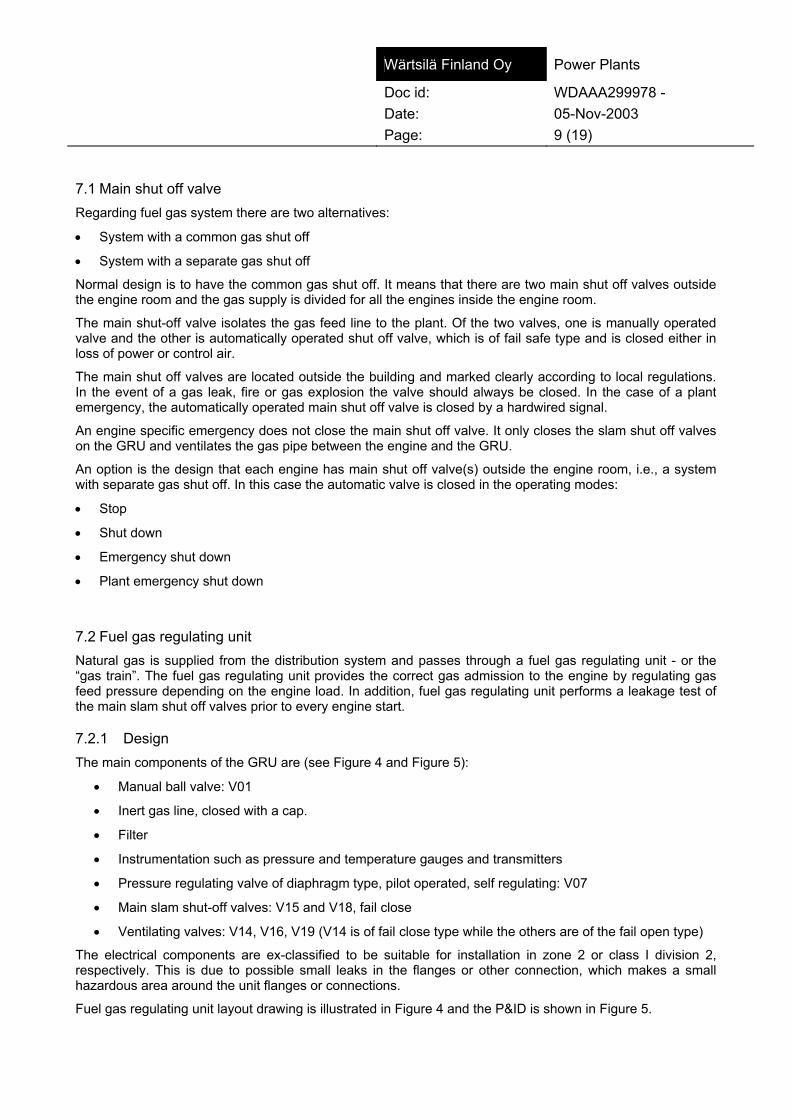
Wärtsilä Finland Oy Power Plants
Doc id: WDAAA299978 - Date: 05-Nov-2003 Page: 9 (19) 7.1 Main shut off valve Regarding fuel gas system there are two alternatives:
• System with a common gas shut off
• System with a separate gas shut off
Normal design is to have the common gas shut off. It means that there are two main shut off valves outside the engine room and the gas supply is divided for all the engines inside the engine room.
The main shut-off valve isolates the gas feed line to the plant. Of the two valves, one is manually operated valve and the other is automatically operated shut off valve, which is of fail safe type and is closed either in loss of power or control air.
The main shut off valves are located outside the building and marked clearly according to local regulations. In the event of a gas leak, fire or gas explosion the valve should always be closed. In the case of a plant emergency, the automatically operated main shut off valve is closed by a hardwired signal.
An engine specific emergency does not close the main shut off valve. It only closes the slam shut off valves on the GRU and ventilates the gas pipe between the engine and the GRU.
An option is the design that each engine has main shut off valve(s) outside the engine room, i.e., a system with separate gas shut off. In this case the automatic valve is closed in the operating modes:
• Stop
• Shut down
• Emergency shut down
• Plant emergency shut down
7.2 Fuel gas regulating unit Natural gas is supplied from the distribution system and passes through a fuel gas regulating unit - or the “gas train”. The fuel gas regulating unit provides the correct gas admission to the engine by regulating gas feed pressure depending on the engine load. In addition, fuel gas regulating unit performs a leakage test of the main slam shut off valves prior to every engine start.
7.2.1 Design The main components of the GRU are (see Figure 4 and Figure 5):
• Manual ball valve: V01
• Inert gas line, closed with a cap.
• Filter
• Instrumentation such as pressure and temperature gauges and transmitters
• Pressure regulating valve of diaphragm type, pilot operated, self regulating: V07
• Main slam shut-off valves: V15 and V18, fail close
• Ventilating valves: V14, V16, V19 (V14 is of fail close type while the others are of the fail open type)
The electrical components are ex-classified to be suitable for installation in zone 2 or class I division 2, respectively. This is due to possible small leaks in the flanges or other connection, which makes a small hazardous area around the unit flanges or connections.
Fuel gas regulating unit layout drawing is illustrated in Figure 4 and the P&ID is shown in Figure 5.

Wärtsilä Finland Oy Power Plants
Doc id: WDAAA299978 - Date: 05-Nov-2003 Page: 10 (19)
VentVent Vent
Ball valve Filter
Pilot operated
Downstream pipe Electro-pneumatic
Main Pressure Regulator
shut-off valves
Control Air Compressed Air
Figure 4 Typical fuel gas regulating unit layout.
Figure 5 The P&ID of the fuel gas regulating unit.
The GRU includes shut-off valves and ventilation valves, which are located in the vent pipes. These vent pipes are drawn as two separate lines up to the roof (see Figure 5). This is a hazardous area and it is marked on the layouts as such (see Figure 1).
Vent no 1 Vent no 2

Wärtsilä Finland Oy Power Plants
Doc id: WDAAA299978 - Date: 05-Nov-2003 Page: 11 (19) Figure 6 shows the pressure regulator in the GRU.
Figure 6 The pressure regulator with functional units regulator, pilot valve and SAV valve.
The pilot operated pressure regulator is operated using control air from I/P converter.
The regulator consists of the main valve body and the functional units “regulator”, “pilot valve” and “safety shut-off valve” (SAV).
Safety shut-off valve (SAV)
An additional safety shut-off valve may be installed if the inlet pressure to the GRU is higher than 6 bar. The control element of the safety shut-off valve is installed on the inlet side of the body and shuts off the gas flow if the outlet pressure in the main gas line rises above the pre-set limits. On detecting high pressure the SAV measuring diaphragm and the switching bush move into the release position and the ball mechanism set the valve stem free to close the SAV valve.
The safety shut-off valve can only be reopened by hand, after the outlet pressure at the measuring point has been restored to a value below the re-engagement differential. If the SAV valve is closed, it will lead to a shut down of the engine and depressurisation of the piping after regulating valve V07 resulting is the pressure automatically decreased below the re-engagement differential.
Thus the following shall be done:
• Reopen the SAV valve first slowly by dragging slightly (pressures will equalise)
• After equalising open the valve completely
This is required to enable a safe and easy re-engagement of the SAV valve.
There is a feedback signal in the SAV to monitor the valve.
Figure 7 shows the main slam shut off valves in the GRU.
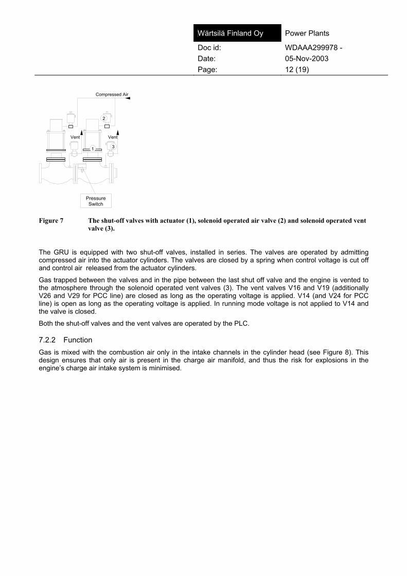
Wärtsilä Finland Oy Power Plants
Doc id: WDAAA299978 - Date: 05-Nov-2003 Page: 12 (19)
Compressed Air
Pressure Transmitter
1
2
3
VentVent
PressureSwitch
Figure 7 The shut-off valves with actuator (1), solenoid operated air valve (2) and solenoid operated vent valve (3).
The GRU is equipped with two shut-off valves, installed in series. The valves are operated by admitting compressed air into the actuator cylinders. The valves are closed by a spring when control voltage is cut off and control air released from the actuator cylinders.
Gas trapped between the valves and in the pipe between the last shut off valve and the engine is vented to the atmosphere through the solenoid operated vent valves (3). The vent valves V16 and V19 (additionally V26 and V29 for PCC line) are closed as long as the operating voltage is applied. V14 (and V24 for PCC line) is open as long as the operating voltage is applied. In running mode voltage is not applied to V14 and the valve is closed.
Both the shut-off valves and the vent valves are operated by the PLC.
7.2.2 Function Gas is mixed with the combustion air only in the intake channels in the cylinder head (see Figure 8). This design ensures that only air is present in the charge air manifold, and thus the risk for explosions in the engine’s charge air intake system is minimised.
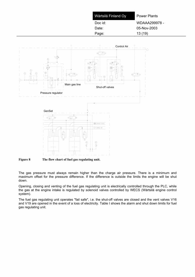
Wärtsilä Finland Oy Power Plants
Doc id: WDAAA299978 - Date: 05-Nov-2003 Page: 13 (19)
Main gas line
Pressure regulator
Shut-off valves
Control Air
GenSet
Figure 8 The flow chart of fuel gas regulating unit.
The gas pressure must always remain higher than the charge air pressure. There is a minimum and maximum offset for the pressure difference. If the difference is outside the limits the engine will be shut down.
Opening, closing and venting of the fuel gas regulating unit is electrically controlled through the PLC, while the gas at the engine intake is regulated by solenoid valves controlled by WECS (Wärtsilä engine control system).
The fuel gas regulating unit operates "fail safe", i.e. the shut-off valves are closed and the vent valves V16 and V19 are opened in the event of a loss of electricity. Table I shows the alarm and shut down limits for fuel gas regulating unit.
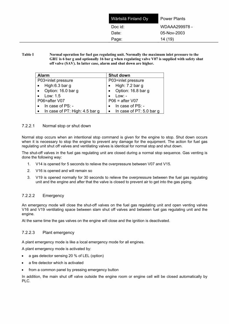
Wärtsilä Finland Oy Power Plants
Doc id: WDAAA299978 - Date: 05-Nov-2003 Page: 14 (19) Table I Normal operation for fuel gas regulating unit. Normally the maximum inlet pressure to the
GRU is 6 bar g and optionally 16 bar g when regulating valve V07 is supplied with safety shut off valve (SAV). In latter case, alarm and shut down are higher.
Alarm Shut down P03=inlet pressure • High:6.3 bar g • Option: 16.0 bar g • Low: 1.5 P06=after V07 • In case of PS: - • In case of PT: High: 4.5 bar g
P03=inlet pressure • High: 7.2 bar g • Option: 16.8 bar g • Low: - P06 = after V07 • In case of PS: - • In case of PT: 5.0 bar g
7.2.2.1 Normal stop or shut down
Normal stop occurs when an intentional stop command is given for the engine to stop. Shut down occurs when it is necessary to stop the engine to prevent any damage for the equipment. The action for fuel gas regulating unit shut off valves and ventilating valves is identical for normal stop and shut down.
The shut-off valves in the fuel gas regulating unit are closed during a normal stop sequence. Gas venting is done the following way:
1. V14 is opened for 5 seconds to relieve the overpressure between V07 and V15.
2. V16 is opened and will remain so
3. V19 is opened normally for 30 seconds to relieve the overpressure between the fuel gas regulating unit and the engine and after that the valve is closed to prevent air to get into the gas piping.
7.2.2.2 Emergency An emergency mode will close the shut-off valves on the fuel gas regulating unit and open venting valves V16 and V19 ventilating space between slam shut off valves and between fuel gas regulating unit and the engine.
At the same time the gas valves on the engine will close and the ignition is deactivated.
7.2.2.3 Plant emergency A plant emergency mode is like a local emergency mode for all engines.
A plant emergency mode is activated by:
• a gas detector sensing 20 % of LEL (option)
• a fire detector which is activated
• from a common panel by pressing emergency button
In addition, the main shut off valve outside the engine room or engine cell will be closed automatically by PLC.

Wärtsilä Finland Oy Power Plants
Doc id: WDAAA299978 - Date: 05-Nov-2003 Page: 15 (19) Option is that a gas detector only gives an alarm and the operator takes the necessary actions. In this case, a plant emergency mode would only be possible to activate only by pressing emergency button in a common control panel.
7.2.3 Operation of the fuel gas regulating unit
7.2.3.1 Activation of the fuel gas regulating unit It is assumed that all units are shut down but that power is available from the main grid (or an emergency generator). It is also assumed that all units are in operational condition, that the various components of the fuel gas regulating unit have been properly adjusted with the correct control elements (springs, etc.) installed, gas of sufficient quantity, quality and pressure available, and the engine is ready for the start.
Before the planned start of the fuel gas system for the engine, the following should be checked:
1. Make a visual check of the entire unit.
• Check that no work is being performed on the unit, and that all flanges are bolted together and that all connections are installed and secured.
2. Dispose of any unsecured items or debris near the unit that may inhibit operation or could cause injury.
3. Ensure that the engine room is well ventilated and gas free.
4. Check that the main gas valve (manual ball valve) on the fuel gas regulating unit is closed.
5. Check that the gas inlet pressure is normal.
6. Check that the control air pressure is sufficient to operate the system.
7. Check that the manual vent valve on the gas train is closed.
8. Open up all manual shut-off valves to instruments and control units.
9. Check that the safety shut-off function on the pressure regulator is reset.
10. Check that the electrical control system is active and power available.
11. Open the gas main shut-off valve outside the building.
12. Open the main gas valve on the fuel gas regulating unit.
13. Control: that the fuel gas regulating unit is functioning properly.
14. Control: that the shut-off valves are gas tight.
15. Check that the engine is ready for start.
The fuel gas system is now ready and the engine can be started provided that the start blocking circuits for the fuel gas system have not been activated.
Caution! If the fuel gas regulating unit has been opened for maintenance or repair, it is essential to have the unit well purged to remove any trace of air before going ahead with the starting process.
7.2.3.2 Monitoring of the fuel gas regulating unit Note! The following is supplied as general information only. The operating personnel must decide what actions are appropriate for the whole plant, while taking all equipment into consideration.

Wärtsilä Finland Oy Power Plants
Doc id: WDAAA299978 - Date: 05-Nov-2003 Page: 16 (19) The normal operation and supervision of the fuel gas system consist mainly of simple daily checks, such as:
1. Check temperature and pressures in the system.
2. Check the pressure drop over the filtration unit.
• The condition of the filter is important for the reliable operation of the engine.
• The filter should be replaced/cleaned when the condition deteriorates.
• The pressure drop over the filter is 0.05 to 0.1 bar when the filter is new.
• The filter should be cleaned at or before the pressure drop has increased to 0.2 bar (1 bar pressure drop mentioned in the manufacturer's instructions is too high considering the low gas pressure in the main supply line).
3. Check for leakage.
Caution! If gas is found to be leaking into the engine room, it is essential that the engine and the gas supply system are shut down immediately. Leave the engine room and do not enter until the room has been properly ventilated to remove any traces of gas.
7.2.3.3 Shutting down the fuel gas regulating unit for maintenance During normal shutdown, perform the following checks (see Figure 9):
1. Close the main gas valve V01 on the gas train
2. Close the main shut-off valve outside the building.
3. Open the manual ventilation valve V13 if the fuel gas regulating unit is to be shut down for any prolonged time.
Caution! If maintenance is to be performed on any part of the system, this may require closing and locking of the main gas valve V01 (see Figure 5) and ventilating the other parts of the system.
These actions will be decided and taken by local operating personnel.
VentVent Vent
Ball valve Filter
Pilot operated
Downstream pipe Electro-pneumatic
Main Pressure Regulator
shut-off valves
Control Air Compressed Air
Figure 9 Fuel gas regulating unit.
Vent no. 1 Vent no.2

Wärtsilä Finland Oy Power Plants
Doc id: WDAAA299978 - Date: 05-Nov-2003 Page: 17 (19) 7.2.3.4 Emergency stop of the fuel gas regulating unit If the operating condition of the power plant requires an immediate stop of the gas supply to the engine room or engine cell, an emergency stop must be performed as follows:
1. Shut down the engine
• Use any of the emergency stop buttons (installed on the engine control cabinet above the flywheel and on the wall inside the engine room and the control room).
2. Close the main gas valve V01 (see Figure 9: ball valve).
Caution! If the shutdown of the system has been caused by a gas leak it is imperative that all personnel evacuate the room in question immediately. They are not allowed to re-enter the room until it has been properly ventilated to remove any traces of gas.
8 Exhaust gas system
8.1 General The protection of the exhaust gas system is essential part for the safe operation of lean burn gas engine equipped power plant. Main protection methods are:
• Correct design of the system
• Explosion vents (rupture discs) installed in the system
• Exhaust gas ventilation fan operation
In addition, explosion vents should be visually inspected periodically.
8.2 Piping design
The exhaust system is mainly a passive component, i.e. it contains no controllable parts concerning gas safety. The only exception is the ventilation fan that is operated either in engine stop or start sequence.
To minimise the risk of gas explosions in the exhaust system certain safety features are recommended for the design. The following describes the exhaust system design as recommended by Wärtsilä Corporation. For more details, see WDAAA247530.
To minimise the risk of gas building up in the exhaust system it has been designed to contain only upward slopes. Any downward slope creates a pocket where gas can collect in certain circumstances causing a danger of an explosion. However, since the system always contains a silencer, and may be equipped with boiler(s) and catalytic converter(s), all pockets can not be avoided and other means must be used.

Wärtsilä Finland Oy Power Plants
Doc id: WDAAA299978 - Date: 05-Nov-2003 Page: 18 (19) 8.3 Exhaust gas system ventilation The exhaust system is equipped with a ventilation system. The system consists of a centrifugal fan, a flow switch and a butterfly valve equipped with a limit switch. This valve is opened and the fan is started either after every engine stop or before every engine start ventilating the exhaust system. However, in an emergency mode the fan is not operating.
The flow switch confirms that the fan is rotating. The capacity of the fan and the running time of it is chosen such that it is able to change the volume in the exhaust system at least three times during the ventilation run.
Figure 10 shows exhaust gas ventilation system.
SilencerBoiler
fs
Ventilation fan
Flow switch
Ventilation valve
Exhaust stack
Explosion relief valves
Controlsystem
Figure 10 Exhaust gas ventilation system.
8.4 Explosion vents The exhaust system is also equipped with explosion vent valves to relief the excess pressure in the exhaust system in the event of an explosion. The general rule is that the diameter of the explosion vent is at least of the same as the exhaust gas pipe diameter. In addition, the vent duct above the explosion vent is of the same diameter as the explosion vent. The length of the vent duct shall be minimised in order to reduce the back pressure from the vent duct in an explosion. The explosion vent valve is designed to open at an excess pressure of 0.5 ± 0.05 bar at operating temperature.
The first explosion vent valve is located after the turbochargers. In a straight pipe, explosion vent valves shall be installed every ten diameters.
Wärtsilä Finland Oy Power Plants
Doc id: WDAAA299978 - Date: 05-Nov-2003 Page: 19 (19) The silencer inlet and outlets are also equipped with explosion vents. The explosion vent in the inlet may have been omitted if the distance from the previous explosion vent is less than 5 times the diameter. Only absorption silencers with straight-through design are used. Reactive type silencers with internal chambers are not allowed for lean-burn engines due to their disadvantages during an explosion. Gas may collect in the reactive part in the chambers and thus a violent explosion is possible if unburnt gas is present.
The boiler is equipped with integrated explosion vents at the inlet and outlet of the boiler. The size of these vents is dependent on the boiler design, but should as a minimum be of the same size as the inlet duct to the boiler. If it is impossible to integrate these valves into the boiler, corresponding explosion vents are located in the exhaust gas duct close to inlet and outlet of the boiler.
Explosion vents are ducted outdoors with a duct of at least the same size as the explosion vent. The duct is covered with light-weight noise and weather protection.
The outlet of the duct is located so that personnel are not present during normal operation, and the proximity of the outlet is clearly marked as a hazardous area.
Due to the gas velocities created by a possible explosion, under pressure may be created in the latter parts of the system. Therefore, the stack is dimensioned to sustain an under pressure of 0.3 bar without collapse.
Also, available are active extinguishing systems for explosion prevention, such as explosion suppression. These, however, are not a standard option for lean-burn engine equipped power plants, but have to be considered case by case for special applications. A problem with these is that the actual position of the ignition is not known. Thus the extinguishing system is nearly impossible to design.
Note! After a gas explosion the safety equipment shall be inspected and damaged parts changed for new ones according to manufacturers' instructions. The reason for explosion must be clarified and eliminated before the next start.


04. Maintenance Schedule
04.1 General
The maintenance necessary for the engine is mainly dependent on theoperating conditions. The periods stated in this schedule are guidancevalues only, but must not be exceeded during the guarantee period. Itmay be possible to lengthen the stated maintenance intervals consid-erably depending on the engine load. See also the instruction books ofthe turbocharger separate instructions for additional equipment andchapter 03.
1 Before any steps are taken, carefully read the correspondingitem in this Manual.
2 Note the Risk Reduction in chapter 00A.
3 Note the Environmetal Hazards in chapter 02A.
4 At all maintenance work, observe the utmost cleanliness andorder.
5 Before dismantling, check that all systems concerned aredrained or the pressure released. After dismantling, immediatelycover holes for lubricating oil, gas and air with tape, plugs, clean clothor the like.
6 When exchanging a worn-out or damaged part providedwith an identification mark stating cylinder or bearing number, markthe new part with the same number on the same spot. Every exchangeshould be entered in the engine log and the reason should be clearlystated.
7 Always renew all gaskets, sealing rings and O-rings atmaintenance work. Note! The O-rings in the cooling water systemmust not be lubricated with oil based lubricants, use soap or similar.
8 After reassembling, check that all screws and nuts are tight-ened and locked, if necessary.
Caution! When overhauling the engine, make absolutely sure that the auto-matic start and the priming pump are disconnected. Make also surethat the starting air shut-off valve located before main starting valveis closed. Then drain the engine starting air system to avoid enginedamage and/or personal injury.
Caution! When overhauling the engine, make absolutely sure that the gen-erator breaker is secured/gear box is not engaged to avoid acci-dental turning of engine.
34SG-200349-10 Maintenance Schedule
04 - 1

Caution! Accidental turning of engine may cause engine damage and/orpersonal injury.
04.2 Every second day, irrespective of the engine being in operation or not
Automatic prelubrication Check operation 03.218.9
04.3 Once a week irrespective of the engine being in operation or not
Start process Test start (if the engine on stand-by). 03.2
04.4 Interval: 50 operating hoursAir coolers Check draining of air coolers 15.9
Check that the draining pipes are open, check if any leakage. 03.4.1
Automation Check operating values 03.4.1
Check and record all operating values.
Cooling water system Check water level in cooling system 19.1.4
Check the water level in the expansion tank(s) and/or thestatic pressure in the engine cooling circuits.
Connecting rod Check tightening of the connecting rod screws 11.3.4
Check the tightening of the connecting rod screws after thefirst 50 operating hours on a new engine and, after overhaul,those screws that have been opened.Note! Pump to stated pressure. Tighten if possible. Do not loosen!
07.3
Gas and lub. oil filters Check pressure drop indicators 03.4.1
Replace filter cartridges if high pressure drop is indicated. 17.218.7
Lubricating oil sump Check oil level in sump 18.2
Check oil level by means of dip stick, compensate forconsumption.
02.2
Main bearings Check tightening of main bearing screws 10.2.3
Check the tightening of main bearing screws after the first 50operating hours on a new engine and, after overhaul, thosescrews that have been opened.Note! Pump to stated pressure. Tighten if possible. Do not loosen!
07.3
Running-in filter Remove the running-in filterAfter the first 50 operating hours, remove the running-in filterand pump up the hydraulic jack.
Turbocharger Water cleaning of compressor 15.3.3
Clean the compressor by injecting water.
Valve mechanism Check valve clearances 12.2.4
Check the valve clearances after 50 hours’ running in newand overhauled engines.
06.1
Maintenance Schedule 34SG-200349-10
04 - 2

04.5 Interval: 500 operating hoursCooling water Check water quality 19.2
Check content of additives. 02.3
Lubricating oil Take oil sample 02.2.3
In a new installation or after change to use of a new lub-ricating oil brand, take samples for analyzing.
04.6 Interval: 1000 operating hoursAir filter (on-built) Clean turbocharger air filter 15.2
Remove the filter(s) and clean according to instructions of themanufacturer (more often, if necessary).
El. lubricating oil pump Regrease prelubricating pump 18.9
Regrease the pump under running condition.
Flexible coupling Oil change/check of the couplingGeislinger (Oil filled) At first interval, change oil of the coupling.
Following (1000h) intervals, check oil level.See manufacturersinstructions.
Gas filter Replace gas filter cartridgesEngine mounted
On gas regulating unit
Clean the filter housing. The engine mounted filter cartridgecan be cleaned by pressurized air from inside, replacecartridge if necessary. Gas regulating unit, replace the filter cartridges. Following intervals for both filters 4000 hours .
17.117.2
Ignition system Clean and check the condition of the extension 16.4.4
Replace O-rings.
Ignition system Replace spark plugs 16.4.3
Prechamber non-returnvalve
Clean and check the non-return valve 16.3
Clean the valve. Replace the spring. Check for wear, replaceparts if necessary.
04.7 Interval: 2000 operating hoursAir cooler(s) Check water side of charge air cooler(s) 15.9
The first time check and possible cleaning of the waterside. Ifin good condition and deposits insignificant: future intervals4000 running hours.
Centrifugal filter Clean centrifugal filter(s) 18.8.2
Clean more often if necessary. Remember to open the valvebefore the filter after cleaning.
Gas system Maintenance of gas systemMake the leak test. 17.3
Lubricating oil filter Replace lub. oil filter cartridges 18.7.2
Drain the filter housings. Clean the wire gauze and filterhousing. Replace the filter cartridges. (The cartridges are tobe replaced when the pressure difference indicator showstoo high pressure drop.)
Continue
18.2
34SG-200349-10 Maintenance Schedule
04 - 3

Lubricating oil Change lubricating oil 18.2
Change oil in a new installation (wet sump installations). Takesamples for analyzing. If the analyzing values are positive andif the oil supplier or engine manufacturer so recommend, theintervals between changes can be based on regular analyzing. In wet sump installations the oil change intervals may be in theorder of 6000 hours or more. Clean all oil spaces when changing lub. oil.
02.2
Valves Check valve clearances 12.2.4
Check valve clearances.
04.8 Interval: 4000 operating hoursAir cooler(s) Clean the charge air cooler(s) 15.9
Clean and pressure test. Look carefully for corrosion.Measure the pressure difference over the charge air coolerbefore and after cleaning. Use U-gauge.
Automation Check connectors and cables 23.13
Check mounting and connections. Apply contact lubricant tocontact surfaces. Check tightness of connections. Checkcondition of cables, wires and cable glands. Replacedamaged connectors and cables.
23.14
Camshaft Inspect contact faces of camshaft 14.1.3
Check the contact faces of the cams and tappet rollers. Checkthat the rollers rotate. Rotate the engine with the turning gear.
03.1
Cooling water spaces Inspect jacket water spaces on engine with cooledturbocharger
15.2
Inspect turbocharger cooling water ducts for possible deposits.If the deposits are 1mm or thicker, inspect the water side ofone cylinder liner through the plug in the engine block. If thedeposits are thicker than 1 mm, clean all liners and engineblock water space. Improve the cooling water treatment.
19.219.1.202.310.5
Inspect jacket water spaces on engine withuncooled turbocharger
15.2
Inspect the water side of one cylinder through the plug in theengine block. If the deposits are thicker than 1 mm, clean allliners and engine block water space. Improve the coolingwater treatment.
19.219.1.202.310.5
Crankshaft Check crankshaft alignment 11.2.2
Check alignment, use form No. WV98V036. Alignment checkis performed on a warm engine.
Crankshaft Check thrust bearing clearance 11.2.3
Check axial clearance. 06.2
Flexible coupling Oil change of the couplingGeislinger (Oil filled) Change oil of the coupling.
See manufacturers instructions.
Gas filter Replace gas filter cartridgesEngine mounted
On gas regulating unit
Clean the filter housing. Replace the engine mounted filtercartridge. Gas regulating unit, replace the filter cartridges.
Continue
17.117.2
Maintenance Schedule 34SG-200349-10
04 - 4

Starting air system Clean the starting air filterClean the filter and replace sealing’s.
Valves and piston rings Check cylinder tightness 12.A
Check cylinder tightness (valves, piston rings) with a pneumatictest.
04.9 Interval: 8000 operating hoursExhaust manifold Check for leaks 20.
Replace parts if necessary.Gas admission valves Replace the main and prechamber gas admission
valves17.417.5
Hoerbiger Replace also the female connector.Gas regulating unit Overhaul of gas pressure regulating and safety shut-
off valvesSee manufacturers instructions.
Lube oil coolers Clean the lube oil cooler 18.5
If the lube oil temperature before the engine is within normaloperating values (Section 01.1), the interval can beprolonged. Unnecessary opening of the plate cooler shouldbe avoided. Clean the lube oil cooler before the alarm limit isreached. Examine carefully for corrosion.
19.2
Starting motors Check the starting motorsCheck the starting motors gear wheels and flywheel gear rim.Check oil level, and look for leaks. See manufacturersinstructions.
21.2
Wastegate Check the function of the wastegate valve and actuatorReplace the positioner pilot valve.
04.10 Interval: 12000 operating hoursHT-water pump Inspect HT-water pump 19.3.1
Dismantle and check. Replace worn parts. 19.3.2
HT-water pump driving gear Inspect HT-water pump driving gear 19.3.1
Replace parts if necessary. 06.2
HT-water thermostatic valve Clean and inspect HT-water thermostatic valve 19.1
Clean and check the thermostatic element, valve cone-cas-ing and sealing’s.
LT-water pump Inspect LT-water pump 19.3.1
Dismantle and check. Replace worn parts. 19.3.2
LT-water pump driving gear Inspect LT-water pump driving gear 19.3.1
Replace parts if necessary. 06.2
LT-water thermostatic valve Clean and inspect LT-water thermostatic valve 19.4.1
Clean and check the thermostatic element, valve cone-cas-ing and sealing’s.
19.4.2
Lube oil pump Inspect the lube oil pump 18.3.3
Replace parts if necessary.Continue
34SG-200349-10 Maintenance Schedule
04 - 5

Lube oil pump driving gear Inspect lube oil pump driving gear 18.3.4
Replace parts if necessary. 06.2
Oil thermostatic valve Clean and inspect oil thermostatic valve 18.6
Clean and check the thermostatic element, valve cone-cas-ing and sealing’s.
Turbocharger Inspect turbocharger bearings 15.2
Napier NA-chargers Check and change if necessary.See manufacturers instructions.
Turbocharger Inspect turbocharger bearings 15.2
ABB TPL-chargers Check and change if necessary.See manufacturers instructions.
Turbocharger Inspect turbocharger bearings 15.2
Hispano Suiza-chargers Check and change if necessary.See manufacturers instructions.
04.11 Interval: 16000 operating hoursCamshaft Inspect camshaft bearings 10.4.1
Replace if necessary. 06.2
Camshaft driving gear Inspect intermediate gears 13.1
Replace parts if necessary. 06.2
Connecting rods Replace big end bearing 11.3.3
Replace big end bearing. Inspect mating surfaces. Measurethe big end bore, use form No. 3211V012.
06.2
Connecting rods Inspect the small end bearingsInspect the small end bearings. Replace if necessary. 11.3.3
06.2
Crankshaft Inspect main bearings 10.2.2
Inspect one main bearing. If in bad condition, check/changeall main bearings. Note the type of bearing in use and do theinspection accordingly.
06.2
Cylinder heads Overhaul of cylinder head 12.2.3
Dismantle and clean the underside, inlet and exhaust valvesand ports. Inspect cooling spaces and clean, if necessary.Grind the valves. Inspect the valve rotators. Check rockerarms.Replace the O-rings in the valve guides and on the exhaustvalve seat rings.Replace the O-rings at bottom of cylinder head screws atevery overhaul.Replace the knocking sensors by new ones.
12.212.314.1.3
Cylinder liners Inspect the cylinder liners 10.5.1
Measure the bore using form No. 3410V019, replace liner ifwear limits are exceeded. Hone the liners. Renew the anti-polishing ring.
06.2
Cylinder liners Inspect cylinder liner water side 19.2
Pull all cylinder liners. If the deposits are thicker than 1 mm,clean all liners and the engine block water space. Replacethe O-rings in the bottom part by new ones at every overhaul
Continue
10.5
Maintenance Schedule 34SG-200349-10
04 - 6

Flexible coupling(Oil filled)
Check the flexible coupling
Dismantle and check flexible coupling acc. to manufacturersrecommendations.
Gas admission valves Replace the main and prechamber gas admissionvalves
17.417.5
Woodward In installations where connectors used, replace also thefemale connector.
Gas admission valves Clean the main gas admission valve filter insert 17.417.5
Woodward Clean the main gas admission valve filter insert. Replace ifneeded.
Gas system Maintenance of gas systemReplace sealing’s in pipe connections, check sealing facesfor wear and corrosion. Make the leak test. 17.3
Hydraulic jack Check function
Replace O-rings in the hydraulic jack if they are leaking whenlifting the main bearing cap.
10.2.1
Pistons Inspect the pistonsComposite pistons must be dismantled for inspection ofmating surfaces between piston skirt and piston crown.Inspect and clean oil spaces.
11.B
Pistons, piston rings Inspect pistons and replace piston rings 11.3.3
Pull, inspect and clean. Check the height of the ring grooves,use form No. 3410V023.Check the retainer rings of the gudgeon pins. Replacecomplete set of piston rings. Note the running-in programme.
11.306.203.8
Prechamber Clean the nozzlesClean the nozzles and check for wear and cracks. Replaceprechamber if necessary. Replace the O-rings and thebottom sealing ring.
16.3
Turning device Change oil in turning device 02.2.5
Regrease the drive shaft. 03.9
Valve mechanism Check valve mechanism parts 14.1.3
Check tappets. 06.2
Vibration damper Take oil sample from vibration damper 11.2.1
Viscous type Take oil sample for analyzing.
04.12 Interval: 24000 operating hoursEngine fastening bolts Check tightening of engine fastening bolts 07.3
Replace if necessary.Exhaust manifold Check expansion bellows 20.2
Replace if necessary.Flexible coupling(Oil supply from engine)
Check the flexible coupling
Dismantle and check flexible coupling acc. to manufacturersrecommendations.
Turbocharger Replace turbocharger bearings 15.2
Replace turbocharger bearings.See manufacturers instructions.
34SG-200349-10 Maintenance Schedule
04 - 7

04.13 Interval: 32000 operating hoursConnecting rods Replace connecting rod screws
Replace connecting rod screws at latest 32 000 h with newones.
11.3.306.2
Connecting rods Replace connecting rod shimsReplace connecting rod shims at latest 32 000 h with newones.
11.3.306.2
Turbocharger Check rotor balance 15.2
Napier Check rotor balance every 32 000 hours or every 4 years. Seemanufacturers instructions.
15.5
04.14 Interval: 48000 operating hoursCamshaft driving gear Replace intermediate gear bearings 13.1
Replace parts. 06.2
Crankshaft Inspect crankshaftInspect the crankshaft for wear. 06.2
Engine foundation Check flexible elements of engine foundationFlexible mounted Replace if necessary.
Flexible coupling Check the flexible couplingDismantle and check flexible coupling according to manufacturers instructions.Replace spring packs/inner star if necessary.
Turbocharger Replace rotor 15.2
Lifetime dependent of opereting conditions.See manufacturers instructions.
Maintenance Schedule 34SG-200349-10
04 - 8

05.Maintenance Tools
05.1 General
Maintenance of a engine requires some special tools developed in thecourse of engine design. Some of these tools are supplied with theengine, and others are available through our service stations or fordirect purchase by the customer. Tool requirements for a particular installation may vary greatly,depending on the use and service area. Standard tool sets are thereforeselected to meet basic requirements. This list presents a comprehensive selection of tools for the WärtsiläVasa 32 engine family. Tool sets are grouped in order to facilitate selection for specific serviceoperations. This makes the job of the end-user much easier.
05.1.1.Use of this list
1 Read the corresponding item in this Instruction Book beforeany maintenance work is started.
2 Check with list below that all the maintenance tools are avail-able.
3 Check that necessary spare parts and consumable parts areavailable.
05.1.2.Ordering of Maintenance tools
1 Find the part(s) that interests you in the following pages.
2 Select the tools or parts required, note that tools which arepart of standard deliveries are mentioned in the installation specificdelivery lists. You can use the code number in the following pagewhen ordering.
3 Make a note of the specifications and other information asstated in the “Inquiry/Order List”.
4 Send the order to your local service station printed on theInquiry/Order List. All commercial terms are stated in the In-quiry/Order List. When possible, state installation name and enginenumber(s) when ordering.
Note! This chapter includes all available tools for above mentioned en-gine types. See also the installation specific tool lists. Some of thetools are applicable for certain cylinder numbers and with certainengine mounted equipment.
32-9801 Maintenance Tools
05 - 1
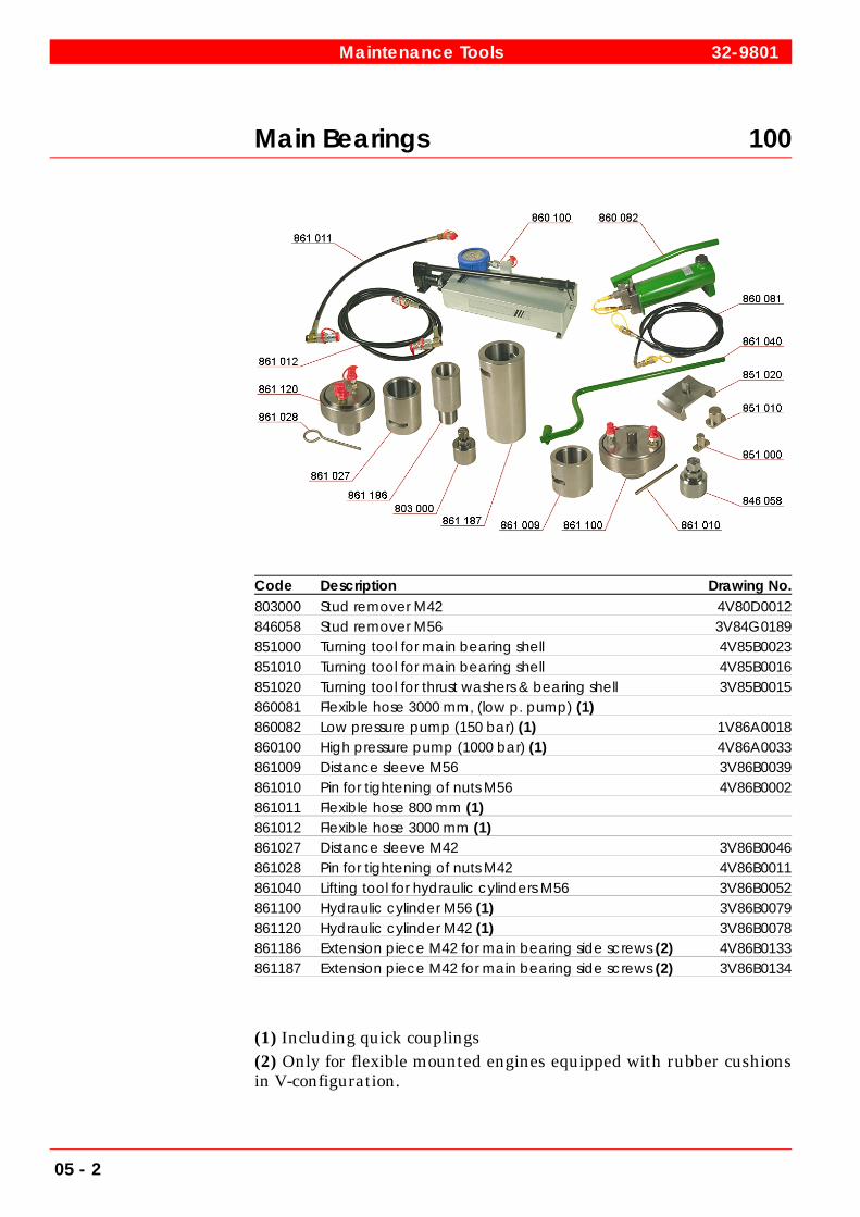
Main Bearings 100
Code Description Drawing No.803000 Stud remover M42 4V80D0012846058 Stud remover M56 3V84G0189851000 Turning tool for main bearing shell 4V85B0023851010 Turning tool for main bearing shell 4V85B0016851020 Turning tool for thrust washers & bearing shell 3V85B0015860081 Flexible hose 3000 mm, (low p. pump) (1)860082 Low pressure pump (150 bar) (1) 1V86A0018860100 High pressure pump (1000 bar) (1) 4V86A0033861009 Distance sleeve M56 3V86B0039861010 Pin for tightening of nuts M56 4V86B0002861011 Flexible hose 800 mm (1)861012 Flexible hose 3000 mm (1)861027 Distance sleeve M42 3V86B0046861028 Pin for tightening of nuts M42 4V86B0011861040 Lifting tool for hydraulic cylinders M56 3V86B0052861100 Hydraulic cylinder M56 (1) 3V86B0079861120 Hydraulic cylinder M42 (1) 3V86B0078861186 Extension piece M42 for main bearing side screws (2) 4V86B0133861187 Extension piece M42 for main bearing side screws (2) 3V86B0134
(1) Including quick couplings(2) Only for flexible mounted engines equipped with rubber cushionsin V-configuration.
Maintenance Tools 32-9801
05 - 2

Cylinder Liner 100
Code Description Drawing No.800009 Dismantling tool for antipolishing ring (1) 2V83G0077834050 Hydraulic extractor 3V83E0061835041 Assembly tool for antipolishing ring 3V83F0105836000 Suspending & removing tool, complete836017 Dismantling tool for antipolishing ring (2) 3V83G0073836018 Lifting tool 3V83G0078836019 Extractor (3)842010 Honing equipment 2V84C0031842025 Honing stones 25x25x250, including holder, coarse842026 Honing stones 25x25x250, including holder, fine860100 High pressure pump (1000 bar) (3) 4V86A0033861012 Flexible hose 3000 mm (3)
(1) Only for 32 DF(2) Code 836017 marked with A only for 34 SG(3) Including quick couplings
32-9801 Maintenance Tools
05 - 3

Connecting Rod, O-Profile 110
Code Description Drawing No.803000 Stud remover M42 4V80D0012835010 Protecting sleeve for connecting rod tooth (1) 4V83F0062835020 Protecting sleeve for connecting rod tooth (1) 2V83F0063846000 Lifting tool for big end bearing cap (1) 1V84G0191860100 High pressure pump (1000 bar) (2) 4V86A0033861011 Flexible hose 800 mm (2)861012 Flexible hose 3000 mm (2)861027 Distance sleeve M42 3V86B0046861028 Pin for tightening of nuts M42 4V86B0011861120 Hydraulic cylinder M42 (2) 3V86B0078
(1) Only needed for V-engine(2) Including quick couplings
Maintenance Tools 32-9801
05 - 4

Connecting Rod, H-Profile 110
Code Description Drawing No.803005 Stud remover M45x3 3V80D0020835010 Protecting sleeve for connecting rod tooth (1) 3V83F0082835020 Protecting sleeve for connecting rod tooth (1) 2V83F0083835030 Mounting screw M45x3 3V83F0084835040 Locking nut for mounting screw 4V83F0085846000 Lifting tool for big end bearing cap (1) 1V84G236860100 High pressure pump (1000 bar) (2) 4V86A0033861011 Flexible hose 800 mm (2)861012 Flexible hose 3000 mm (2)861028 Pin for tightening of nuts M45 4V86B0011861039 Distance sleeve M45x3, long (3) 3V86B0102861039 Distance sleeve M45x3, short (1) 3V86B0136861130 Hydraulic cylinder M45x3 (2) 3V86B0139861141 Extension piece (3) 3V86B0137
(1) Only needed for V-engine(2) Including quick couplings(3) Only for In-line engine
32-9801 Maintenance Tools
05 - 5
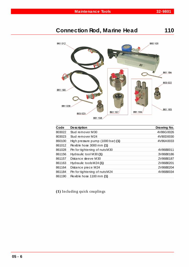
Connection Rod, Marine Head 110
Code Description Drawing No.803022 Stud remover M30 4V86G0026803023 Stud remover M24 4V80D0030860100 High pressure pump (1000 bar) (1) 4V86A0033861012 Flexible hose 3000 mm (1)861028 Pin for tightening of nuts M30 4V86B0011861156 Hydraulic tool M30 (1) 3V86B0186861157 Distance sleeve M30 2V86B0187861163 Hydraulic tools M24 (1) 2V86B0201861164 Distance piece M24 2V86B0204861184 Pin for tightening of nuts M24 4V86B0034861190 Flexible hose 1100 mm (1)
(1) Including quick couplings
Maintenance Tools 32-9801
05 - 6
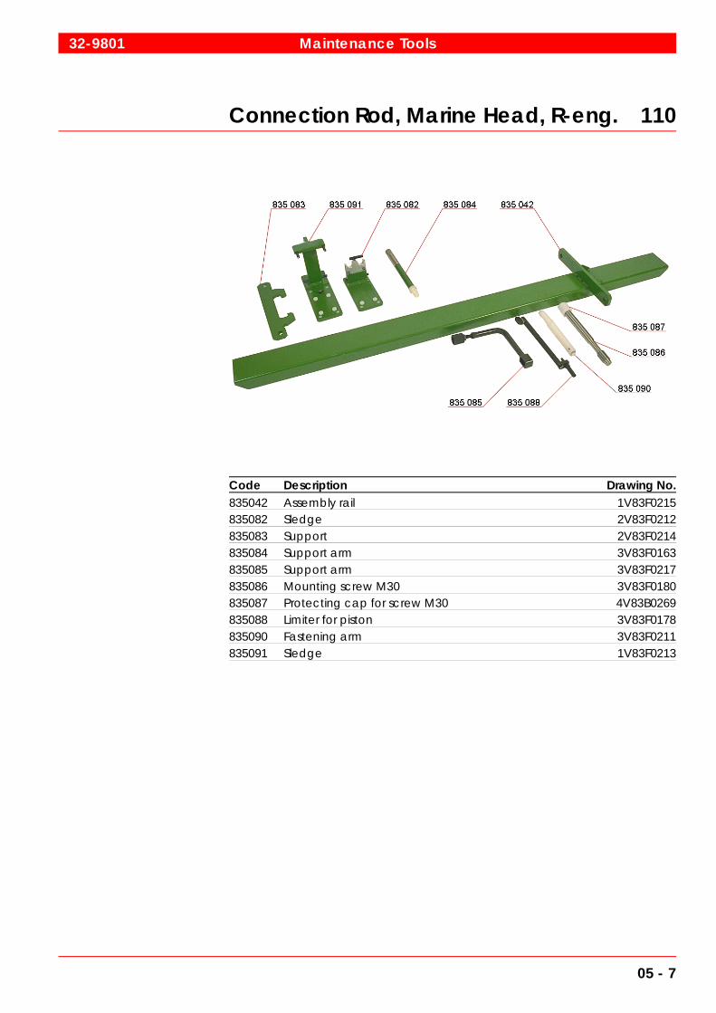
Connection Rod, Marine Head, R-eng. 110
Code Description Drawing No.835042 Assembly rail 1V83F0215835082 Sledge 2V83F0212835083 Support 2V83F0214835084 Support arm 3V83F0163835085 Support arm 3V83F0217835086 Mounting screw M30 3V83F0180835087 Protecting cap for screw M30 4V83B0269835088 Limiter for piston 3V83F0178835090 Fastening arm 3V83F0211835091 Sledge 1V83F0213
32-9801 Maintenance Tools
05 - 7
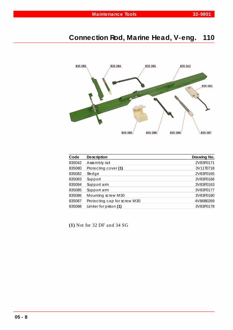
Connection Rod, Marine Head, V-eng. 110
Code Description Drawing No.835042 Assembly rail 2V83F0171835080 Protecting cover (1) 3V11T0718835082 Sledge 2V83F0165835083 Support 3V83F0166835084 Support arm 3V83F0163835085 Support arm 3V83F0177835086 Mounting screw M30 3V83F0180835087 Protecting cap for screw M30 4V86B0269835088 Limiter for piston (1) 3V83F0178
(1) Not for 32 DF and 34 SG
Maintenance Tools 32-9801
05 - 8
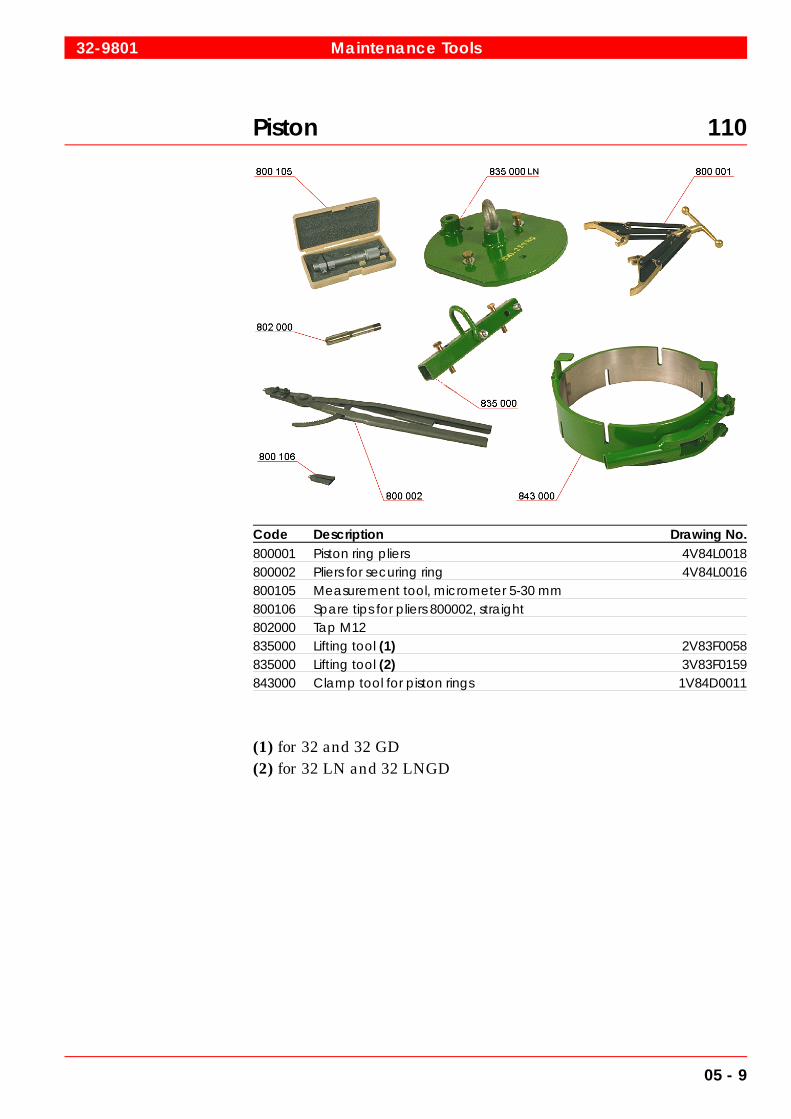
Piston 110
Code Description Drawing No.800001 Piston ring pliers 4V84L0018800002 Pliers for securing ring 4V84L0016800105 Measurement tool, micrometer 5-30 mm800106 Spare tips for pliers 800002, straight802000 Tap M12835000 Lifting tool (1) 2V83F0058835000 Lifting tool (2) 3V83F0159843000 Clamp tool for piston rings 1V84D0011
(1) for 32 and 32 GD(2) for 32 LN and 32 LNGD
32-9801 Maintenance Tools
05 - 9

Piston, 32DF and 34SG 110
Code Description Drawing No.800001 Piston ring pliers 4V84L0018800002 Pliers for securing ring 4V84L0016800105 Measurement tool, micrometer 5-30 mm800106 Spare tips for pliers 800002, straight835000 Lifting tool (1) 2V83F0192835000 Lifting tool (2) 1V83F0221835088 Limiter for piston 3V83F0204835089 Extension for connecting rod 1V83F0190843000 Clamp tool for piston rings 1V84D0043
(1) Only for 34 SG(2) Only for 32 DF
Maintenance Tools 32-9801
05 - 10

Cylinder Head 120
Code Description Drawing No.800000 Pliers for securing ring800010 Stud remover 5-20 4V80L04-1837000 Removing tool for injection & starting valve (1) 4V83H0077837050 Extractor for exhaust valve seat ring 3V-T19189841010 Grinding tool for seal surface, injection valve (1) 3V84B0117841015 Felt washer for grinding tool (1) 4V84B0111841030 Valve seat grinder 4V84B0130846050 Mounting tool for seat rings (inlet & exhaust) 2V-T17415/2846052 Service trestle for cylinder head 0V-T22387848055 Pressure test tool for water jacket D=450 mm 3V-T029310848060 Pressure test tool for water jacket D=440 mm 3V-T022401
(1) Not for 32 DF and 34 SG
32-9801 Maintenance Tools
05 - 11

Cylinder Head 120
Code Description Drawing No.808000 T-wrench for indicator valve (1) 4V80K0006832000 Lifting tool 1V83C0060834000 Mounting & dismantling tool for valves 3V84G0352834050 Hydraulic extractor 3V83E0061841000 Grinding tool for valves 4V84B0108848000 Valve clearance feeler gauge 3V84K0035860100 High pressure pump (1000 bar ) (2) 4V86A0033861009 Distance sleeve M56 3V86B0039861010 Pin for tightening of nuts M56 4V86B0002861011 Flexible hose 800 mm (2)861012 Flexible hose 3000 mm (2)861100 Hydraulic cylinder M56 (2) 3V86B0079
(1) Not for 32 DF and 34 SG(2) Including quick couplings
Maintenance Tools 32-9801
05 - 12
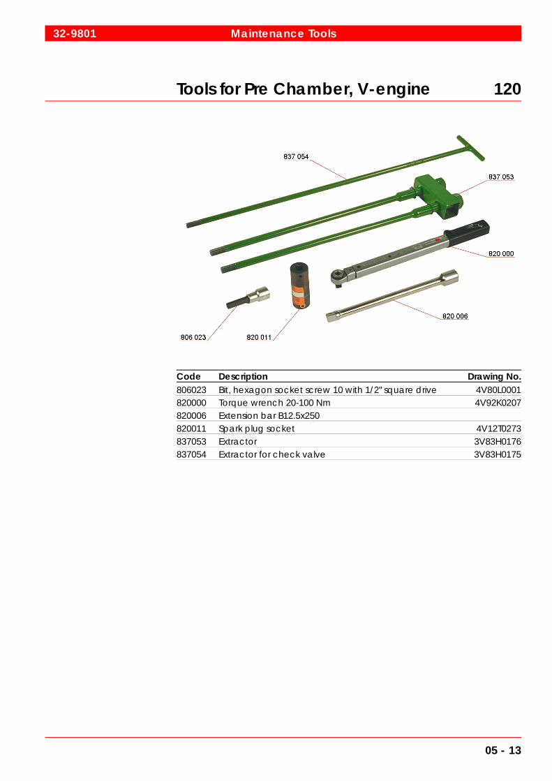
Tools for Pre Chamber, V-engine 120
Code Description Drawing No.806023 Bit, hexagon socket screw 10 with 1/2" square drive 4V80L0001820000 Torque wrench 20-100 Nm 4V92K0207820006 Extension bar B12.5x250820011 Spark plug socket 4V12T0273837053 Extractor 3V83H0176837054 Extractor for check valve 3V83H0175
32-9801 Maintenance Tools
05 - 13

Tools for Intermediate Gear 130
Code Description Drawing No.803010 Mounting tool for shaft 3V80D0013834050 Hydraulic extractor (1) 3V83E0061834053 Mounting & dismantling tool for bearing834055 Mounting tool 3V83E0078834056 Mounting tool 4V83E0080834057 Mounting tool 3V83E0133834058 Mounting tool 3V83E0134834061 Stud for 834057834062 Nut for 834057834063 Extractor for 834057 3V83E0079846058 Stud remover M56 3V83G0189846060 Stud remover M48 3V84G0251860100 High pressure pump (1000 bar) (1) 4V86A0033861010 Pin for tightening of nuts M56 4V86B0002861012 Flexible hose 3000 mm (1)861028 Pin for tightening of nuts M48 4V86B0011861144 Hydraulic cylinder M56 (1) 3V86B0150861145 Distance sleeve M56 3V86B0135861188 Hydraulic cylinder M48 (1) 2V86B127861189 Distance sleeve M48 3V86B0125
(1) Including quick couplings
Maintenance Tools 32-9801
05 - 14
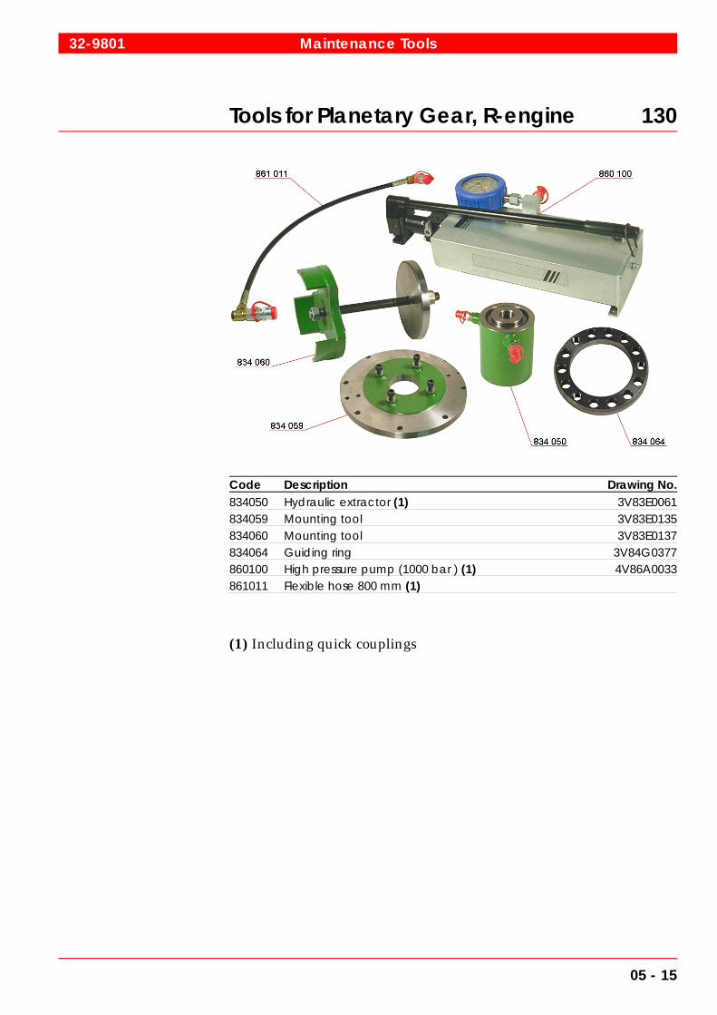
Tools for Planetary Gear, R-engine 130
Code Description Drawing No.834050 Hydraulic extractor (1) 3V83E0061834059 Mounting tool 3V83E0135834060 Mounting tool 3V83E0137834064 Guiding ring 3V84G0377860100 High pressure pump (1000 bar ) (1) 4V86A0033861011 Flexible hose 800 mm (1)
(1) Including quick couplings
32-9801 Maintenance Tools
05 - 15

Injection Equipment 160
Code Description Drawing No.806050 Flare nut wrench for tightening, 36 mm 4V80G0032809018 Long socket wrench 24 x 12.5L with 1/2"809019 Long socket wrench 27 x 12.5L809022 Long socket wrench 41 x 20L with 3/4"820001 Torque wrench 70-330 Nm 4V80L0006831000 Eye bolt for lifting 4V83B0001845020 Nozzle cleaning kit, complete845021 Brass wire brush 4V84L0014845022 Shaft for nozzle needles 4V84L0015845023 50 nozzle needles 4V84L0013862000 Funnel for flowing 3V86C0029863000 Limiter for fuel rack movements 4V86D0004864000 Testing tool for injection valve864006 Pipe 3V86E0029864011 Pressure gauge (400 bar )864012 Pressure gauge (1000 bar ) (1)
(1) Only for 32 LN and 32 LNGD
Maintenance Tools 32-9801
05 - 16

Tools for Multi-Needle injection Valve 160
Code Description Drawing No.806050 Flare nut wrench for tightening, 36 mm 4V80G0032806056 Tightening tool for gas injection valve 4V80G0035807052 Socket wrench 4V80H0017809019 Long socket wrench 27 x 12.5L809033 Long socket wrench 56 x 12.5L809034 Box wrench head 13 4V92K0208820010 Torque wrench 75-400 Nm 4V92K0207820012 Torque wrench 8-40 Nm 4V92K0207831005 Fixing tool for injection valve 2V84G0263837051 Lifting tool 3V83H0163837052 Extractor for gas connection pipe 3V83H0162846057 Assembly tool for gas nozzle 4V84G0334847011 Flange for pressure test 3V84H0057847012 Plug for connection piece 4V31E0212847013 Pressure reducing valve 4V84H0068861012 Flexible hose 3000 mm (1)861149 Quick coupling, male 4V86A0034864009 Testing tool for injection valve 1V86E0091864010 Adapter for nitrogen gas fuel connection 4V86E0110
(1) Including quick couplings
32-9801 Maintenance Tools
05 - 17

Turbocharger 372
Code Description Drawing No.865001 Maintenance tools (1)865002 Blanking tool for turbocharger (1)
(1) State engine number, turbocharger type and serial number / HT-number when ordering.
Maintenance Tools 32-9801
05 - 18

Miscellaneous Tools 900
Code Description Drawing No.805000 Eye bolt screw M10806040 Special key for camshaft flange screws 4V80G0017808010 Resetting tool for overspeed trip 2V80K0009834010 Mounting & removing tool bearing bush (1)834050 Hydraulic Extractor 3V83E0061837010 Extractor for water pump impeller837020 Mounting tool for overspeed trip & elastic link rod 4V83H0073837030 Extractor for water pump impeller845000 Brushes for cleaning of charge air cooler (3-pack) 4V84F0007845010 Brushes for cleaning of lubricating oil cooler (3-pack) 4V84F0006846011 Mounting screw for plate heat exchanger 4V84G0234846030 Adjusting tool for mec. overspeed trip device release 4V84G0232846050 Mounting tool for seat rings (inlet & exhaust) 2V-T17415/2846059 AMP hand crimping tool 4V84G0475
(1) Two versions. Specify inner diameter (150 or 165) of camshaftbearing bush when ordering.
32-9801 Maintenance Tools
05 - 19

Miscellaneous Tools 900
Code Description Drawing No.842024 Service-box for schaller oil mist detect (1)848010 Measure gauge for crankshaft deflection 4V84L0012848020 Checking tool for cylinder / valves tightness849001 Tool locker 4V80L0003860170 Air operated hydraulic unit 4V86B0107861050 Distance sleeve for small counterweight mounting (2) 4V86B0048861055 Distance sleeve for big counterweight mounting (3) 4V86B0081866011 U-manometer for measuring of crankcase pressure 4V86G0037
(1) Only for 32 and 32 LN(2) Only for 9R32(3) Only for 4, 6 ,8R and V-engines
Maintenance Tools 32-9801
05 - 20

Miscellaneous Tools for 32 DF and 34 SG 900
Code Description Drawing No.805000 Eye bolt screw M10806040 Special key for camshaft flange screws 4V80G0017808010 Mounting & removing tool bearing bush (1) 2V83H0173834050 Hydraulic Extractor 3V83E0061837030 Extractor for water pump impeller845000 Brushes for cleaning of charge air cooler (3-pack) 4V84F0007846025 Mounting tool for charge air cooler 2V84G0219846050 Mounting tool for gas seat rings (inlet & exhaust) 2v-T17415/2846059 AMP hand crimping tool 4V84G0475848010 Measure gauge for crankshaft deflection 4V84L0012848020 Checking tool for cylinder / valves tightness (2)849001 Tool locker 4V80L0003860170 Air operated hydraulic unit 4V86B0107861055 Distance sleeve for big counterweight mounting 4V86B0081864013 Testing tool for ignition timing (2) 2V86G0042
(1) Two versions. Specify inner diameter (150 or 165) of camshaftbearing bush when ordering.(2) Only for 34 SG
32-9801 Maintenance Tools
05 - 21

Additional Tools for V-eng. and 4R32 900
Code Description Drawing No.806051 Swivel head 3/4" square drive 4V80H0020834040 Mounting & removing tool for balancing shaft (1)837030 Extractor for water pump impeller 3V-T19189846040 Dismantling tool for thermostat valve 4V84G0218866010 Intermediate piece for measuring gauge 4V86G0033
(1) Only for 4R32
Maintenance Tools 32-9801
05 - 22
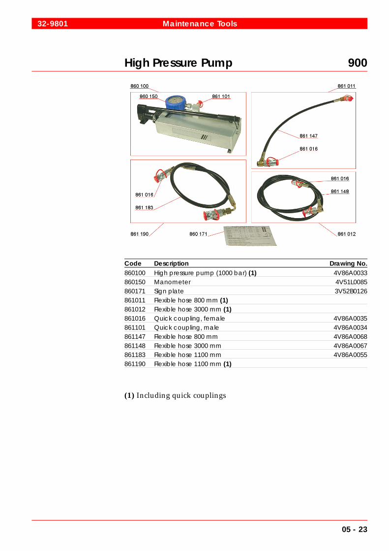
High Pressure Pump 900
Code Description Drawing No.860100 High pressure pump (1000 bar) (1) 4V86A0033860150 Manometer 4V51L0085860171 Sign plate 3V52B0126861011 Flexible hose 800 mm (1)861012 Flexible hose 3000 mm (1)861016 Quick coupling, female 4V86A0035861101 Quick coupling, male 4V86A0034861147 Flexible hose 800 mm 4V86A0068861148 Flexible hose 3000 mm 4V86A0067861183 Flexible hose 1100 mm 4V86A0055861190 Flexible hose 1100 mm (1)
(1) Including quick couplings
32-9801 Maintenance Tools
05 - 23

Low Pressure Pump 900
Code Description Drawing No.860074 Straight male stud 4V34L0135860076 Quick coupling, male 4V86A0012860079 Quick coupling, female 4V86A0012860080 Flexible hose 3000 mm 4V86A0067860081 Flexible hose 3000 mm (1)860082 Low pressure pump (150 bar ) (1) 1V86A0018
(1) Including quick couplings
Maintenance Tools 32-9801
05 - 24

Tightening Tools 900
Code Description Drawing No.806000 Hexagon bar kW 27 4V80G0018820000 Torque wrench 20-100 Nm 4V92K0207820001 Torque wrench 70-330 Nm 4V80L0006820003 Ratchet handle 20 x 630 with 3/4" square drive 4V80K0014820004 Ratchet handle 12.5 x 300 with 1/2" square drive820005 Speed brace B12.5 x 500820006 Extension bar B12.5 x 250, 1/2" square drive820007 Adapter socket wrench A20 x 12.5 with 3/4"x 1/2"820010 Torque wrench 75-400 Nm (1) 4V92K0207820012 Torque wrench 8-40 Nm (1) 4V92K0207
(1) Only for 32 GD and 32 LNGD
32-9801 Maintenance Tools
05 - 25

Hand Tools 900
Code Description Drawing No.803021 Screw driver 2 x 12M 4V84L0019804000 Non recoiling hammer D40 4V80L0005806012 Key for hexagon socket screw 4806013 Key for hexagon socket screw 5806014 Key for hexagon socket screw 6806015 Key for hexagon socket screw 8806016 Key for hexagon socket screw 10806017 Key for hexagon socket screw 12806018 Key for hexagon socket screw 14806019 Key for hexagon socket screw 17806021 Bit, hexagon socket screw 6, 1/2" square drive 4V80L0001806022 Bit, hexagon socket screw 8, 1/2" square drive 4V80L0001806023 Bit, hexagon socket screw 10, 1/2" square drive 4V80L0001806031 Bit, hexagon socket screw 14, 3/4" square drive 4V80L0001806032 Bit, hexagon socket screw 17, 3/4" square drive 4V80L0001806033 Bit, hexagon socket screw 19, 3/4" square drive 4V80L0001806040 Special key for hexagon socket screw 10 4V80G0017809017 Long socket wrench 13 x 12.5L with 1/2" square drive809018 Long socket wrench 24 x 12.5L with 1/2" square drive809021 Long socket wrench 30 x 20L with 3/4" square drive809023 Socket wrench with 30 x 20 3/4" square drive
Maintenance Tools 32-9801
05 - 26

Hand Tools 900
Code Description Drawing No.807001 Box wrench 10-11807002 Box wrench 12-14807003 Box wrench 13-17807004 Box wrench 19-22807005 Box wrench 30-32807011 Engineers wrench 10-11807012 Engineers wrench 12-14807013 Engineers wrench 13-17807014 Engineers wrench 19-22807015 Engineers wrench 24-27807016 Engineers wrench 30-32807017 Engineers wrench 36-41807018 Engineers wrench 46-50807040 Combination wrench AL 36807051 Box wrench 24-27809011 Socket wrench 10 x 12.5 with 1/2" square drive809012 Socket wrench 13 x 12.5 with 1/2" square drive809013 Socket wrench 17 x 12.5 with 1/2" square drive809014 Socket wrench 19 x 12.5 with 1/2" square drive809015 Socket wrench 24 x 12.5 with 1/2" square drive809016 Socket wrench 27 x 12.5 with 1/2" square drive
32-9801 Maintenance Tools
05 - 27

Maintenance Tools 32-9801
05 - 28

06. Adjustments, Clearances and Wear Limits
06.1 Adjustments
06.1.1 Valve timing
The valve timing is fixed and cannot be changed individually, cylinderby cylinder.
Schematic valve timing
Valve clearances, cold engine:. . . . . . . . . . . . . . inlet valves 0.7 mm. . . . . . . . . . . . . . . . . . . . . . . . . . . . . . . . . . . . . exhaust valves 1.2 mm
06.1.2 Set values for overspeed trip devices
Nominal speed Tripping speed OTM-module
720 RPM750 RPM
830 ± 10 RPM860 ± 10 RPM
850 ± 10 RPM885 ± 10 RPM
TDC
BDC
EXH
AUS
TV
ALV
E
INLE
TV
ALV
E
Inlet valve opens Outlet valve closes
Inlet valve closes Outlet valve opens
Fig 06-1 3206549232
34SG-200314-06 Adjustments, Clearances and Wear Limits
06 - 1

06.2 Clearances and wear limits (at 20°C)
Part, measuring pointDrawing dimension (mm) Normal
clearance(mm)
Wear limit(mm)Max. Min.
03 Turning device driving gear backlashdrive gear/ flywheel gear rim 1.20 0.30
10 Main bearing clearance(also flywheel bearing)
0.270-0.374
Journal, diameter 300.000 299.968 299.8 Journal, out of circularity 0.015 0.05Journal, taper 0.015/100 0.025/100Main bearing shell thickness
Trimetal shellsBimetal shells
7.3907.390
7.3707.370
Section 10.2.2
7.32 mm
Bore of main bearing housing 315.032 315.000Assembled bearing bore 300.342 300.270Thrust bearing, axial clearance 0.20-0.46 0.7Thrust washer thickness 14.850 14.800 14.60Camshaft bearing clearance 0.130-0.210 0.36Camshaft diameter 165.000 164.975Camshaft bearing bush, thickness 7.435 7.420Camshaft bearing housing, bore 180.025 180.000Assembled bearing bore 165.200 165.145 165.25Camshaft thrust bearing housing, bore 85.035 85.000Assembled bearing bore 75.125 75.060 75.25Camshaft thrust bearing clearance 0.060-0.144Camshaft thrust bearing, axial clearance 0.250-0.700 1.0Cylinder liner, diameter 340.107 340.050 top: 340.80
bottom: 340.30 Cylinder liner, out of cylindricity at TDC 0.03 0.25Anti-polishing ring, wall thickness 7.25 7.20
11 Big end bearing clearance 0.210-0.304Crank pin, diameter 270.000 269.968 269.920Crank pin, out of circularity 0.015 0.05Crank pin, taper 0.015/100 0.025/100Big end bearing shell thickness
Bimetal shells (Al-based) 5.915 5.900
Section 11.3.3
5.84 mm
Big end boreovality
282.032 282.000 281.90 0.10
Assembled bearing bore 270.272 270.210Gudgeon pin bearing clearance 0.090-0.169Gudgeon pin diameter 150.000 149.986Small end bore 169.955 169.930Assembled bearing bore 150.155 150.090 150.180Connecting rod axial clearance in piston 0.5 -1.0 Small end bearing bush, thickness 9.930 9.910Clearance gudgeon pin - piston 0.010-0.036
Adjustments, Clearances and Wear Limits 34SG-200314-06
06 - 2

Part, measuring pointDrawing dimension (mm) Normal
clearance(mm)
Wear limit(mm)Max. Min.
Bore diameter in piston 150.022 150.010 150.050Compression ring end gaps
(C95)(C86)
1.00 -1.301.30 -1.60
Oil scraper ring end gaps(C87) 1.20 -1.50
Piston ring height clearance:Compression ring ICompression ring II
Oil scraper ring
0.143-0.1950.100-0.1450.063-0.105
0.5 0.5 0.3
Piston ring groove height: Groove IGroove IIGroove III
8.160 6.120 8.080
8.130 6.090 8.050
8.506.458.30
12 Valve guide diameter assembled 24.135 24.100 24.25Valve stem diameter 24.000 23.979 23.95Valve stem clearance 0.100-0.156 0.30Valve seat deviation relative guide(max. value)
0.10
Inlet valve seat bore in cylinder head 112.022 112.000Exhaust valve seat bore in cylinder head
outer boreinner bore
122.025110.022
122.000110.00
Prechamber nozzle holes 6.05 5.95 6.5013 Intermediate gear of camshaft drive
bearing clearanceaxial clearance
0.102-0.1790.33 -0.52
Section10.2.2a
0.70Bearing diameter in situ 120.157 120.102Bearing journal diameter 120.000 119.978Camshaft driving gear backlash:Crankshaft gear wheel (1)/intermediate gear wheel (3) 0.148-0.716Intermediate gear wheel /large intermediate gear wheel (10) 0.178-0.582Small intermediate gear wheel (11)/camshaft gear wheel (12) 0.178-0.582
14 Valve tappet, diameter 79.940 79.910Guide diameter 80.046 80.00 Diameter clearance 0.060-0.136Tappet roller bore diameter 38.025 38.00 Bush diameter, outer 37.975 37.959 37.90Bush diameter, bore 30.028 30.007 30.08Tappet pin diameter 29.993 29.980Bearing clearance roller-bushbush-tappet pin
0.025-0.0660.014-0.048
Rocker arm bearing diameter, in situ 70.109 70.032 70.4 Bearing journal diameter 70.000 69.981Bearing clearance 0.032-0.128Yoke pin diameter 29.935 29.922Yoke bore diameter 30.021 30.000 30.1 Diameter clearance 0.065-0.099
34SG-200314-06 Adjustments, Clearances and Wear Limits
06 - 3

Part, measuring pointDrawing dimension (mm) Normal
clearance(mm)
Wear limit(mm)Max. Min.
18 Lubricating oil pump diameter of shaft 49.920 49.895Bush hole diameter, mounted 50.039 50.000Bearing clearance 0.085-0.190 0.25Axial clearance 0.20 -0.30 Backlash for driving gear - R32
- V320.35-0.490.37-0.57
Base tangent length - R32for driving gear - V32
86.66286.064
86.62686.016
19 Water pump backlash - R32for driving gear - V32
0.54-0.680.57-0.68
Base tangent length - R32- V32
53.80161.228
53.75961.186
53.60
21 Backlash for starting motor drive 0.5-0.8
Adjustments, Clearances and Wear Limits 34SG-200314-06
06 - 4

07. Tightening Torques and Use of HydraulicTools
07.1 Tightening torques for screws and nuts
Note! See section 07.3 for hydraulically tightened connections!
The position numbers in the tables below refer to the correspondingfigures A to I, which are located in the engine according to Fig 07-1.Always tighten to stated torque shown in the tables. A loosen screwconnection might cause serious damages/human injury.Threads andcontact faces of nuts and screw heads should be oiled with lubricatingoil unless otherwise stated. Note that locking fluids are used in certaincases.
Note! Molycote or similar low friction lubricants must not be used for anyscrews or nuts. Great risk of over tensioning of screws.
1 Nm = 0.102 kpm
Tightening torques
A
B
C
D
G
H
I
E
F
Fig 07-1 3207130338
34SG-200339-09 Tightening Torques and Use of Hydraulic Tools
07 - 1
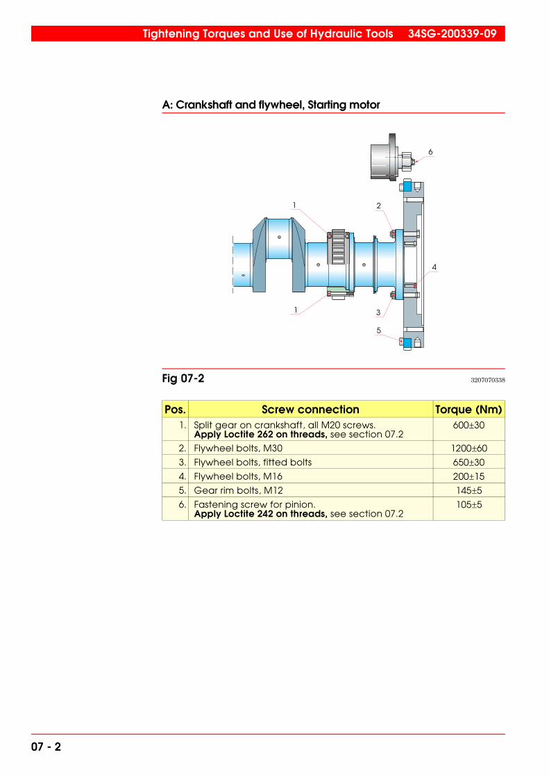
A: Crankshaft and flywheel, Starting motor
Pos. Screw connection Torque (Nm)1. Split gear on crankshaft, all M20 screws.
Apply Loctite 262 on threads, see section 07.2600�30
2. Flywheel bolts, M30 1200�60
3. Flywheel bolts, fitted bolts 650�30
4. Flywheel bolts, M16 200�15
5. Gear rim bolts, M12 145�5
6. Fastening screw for pinion.Apply Loctite 242 on threads, see section 07.2
105�5
1 2
3
4
5
1
6
Fig 07-2 3207070338
Tightening Torques and Use of Hydraulic Tools 34SG-200339-09
07 - 2

B: Intermediate gear
Pos. Screw connection Torque (Nm)1. Centre bolts, M56 200�10
2. Shaft bolts, M8 23�1
3. Fastening bolts, M12 85�5
4. Shaft plate bolts, M10.Apply Loctite 243 on threads, see section 07.2
45�5
5. Cover bolts, M10. 45�5
Note! See section 07.3 for hydraulically tightened connections!
5
4
32
1
Fig 07-3 3207579045
34SG-200339-09 Tightening Torques and Use of Hydraulic Tools
07 - 3

C: Camshaft and control mechanism
Pos. Screw connection Torque (Nm)1. Camshaft flange connection screws.
Torque wrench setting with tool 4V80G17 (806040).The screws are treated with locking compoundand can be used only once. Replace the screwswith new, treated ones. Only Driloc 201 or Driloc211 should be used.
160�5135
2. Camshaft gear, flange connection screws.Apply Loctite 243 on threads, see section 07.2
130�5
3. Housing fastening screws. 85�5
4. Extension piece, flange connection screws.Apply Loctite 243 on threads, see section 07.2
45�5
Note! Torque wrench settings must be recalculated if another tool com-bination than 4V80G17 (item 17-37 in chapter 05) and torquewrench (item 16-02 in chapter 05) is used for the camshaft flangeconnection.
75 L=430 mm
M = 135 Nm
M= 160 Nm
1
M = 160 L
L+751 *
1 2 3
4
Fig 07-4 3207029720
Tightening Torques and Use of Hydraulic Tools 34SG-200339-09
07 - 4

D: Cylinder head
Pos. Screw connection Torque (Nm)1. Rocker arm console, fastening nuts. When re-
assembling stud bolts apply Loctite 270 on threads,see section 07.2
250�10
2. Prechamber fastening nuts 130�5
3. Nuts for valve tappet guide blockNote! The studs must be locked with Loctite 243.
200�10
4. Plug for cylinder head (with steel sealing ring) 45�5
5. Screw for knocking sensorBoschPCB
20�56�1
6. Sensor pockets for exhaust gas temperature.Note! Pockets mounted in the cylinderhead.
10�1
1
4
6
5
3
2
Fig 07-5 3207039720
34SG-200339-09 Tightening Torques and Use of Hydraulic Tools
07 - 5
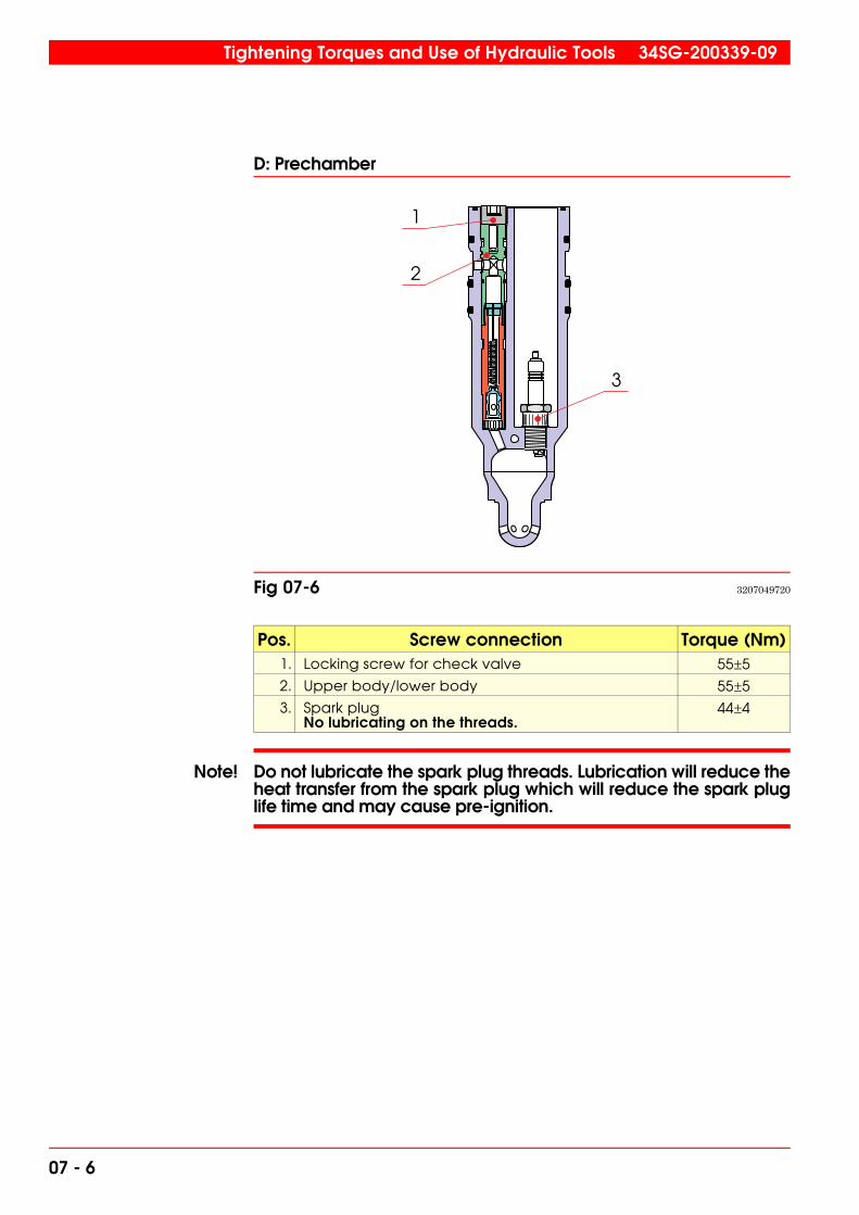
D: Prechamber
Pos. Screw connection Torque (Nm)1. Locking screw for check valve 55�5
2. Upper body/lower body 55�5
3. Spark plug No lubricating on the threads.
44�4
Note! Do not lubricate the spark plug threads. Lubrication will reduce theheat transfer from the spark plug which will reduce the spark pluglife time and may cause pre-ignition.
2
3
1
Fig 07-6 3207049720
Tightening Torques and Use of Hydraulic Tools 34SG-200339-09
07 - 6

D: Main gas admission valve
Screw connectionTorque (Nm)
Type 1 Type 21. Valve fastening screws 20-2 25�5
2. Screws for pipe connections 25�5 25�5
1
2
1
2
Type 1 Type 2
Fig 07-7 3207059720
34SG-200339-09 Tightening Torques and Use of Hydraulic Tools
07 - 7

E: Piston
Piston Torque (Nm)5. Piston crown connection screws.
1. Lubricate threads and contact surfaces with Molycote Paste G-n-plus.2. Tighten the screws crosswise.3. Loosen the screws. 4. Pre-tighten the screws crosswise.5. Tighten the screws crosswise further with an angle of6. Test for the right tightness. Screw should not move when tightening by 65 Nm torque.Note! If the free length of the screws exceeds 166 mm the screws must be replaced.
80 Nm
20 Nm
90°
5
Piston of type 1
Fig 07-8 3207959542
Tightening Torques and Use of Hydraulic Tools 34SG-200339-09
07 - 8
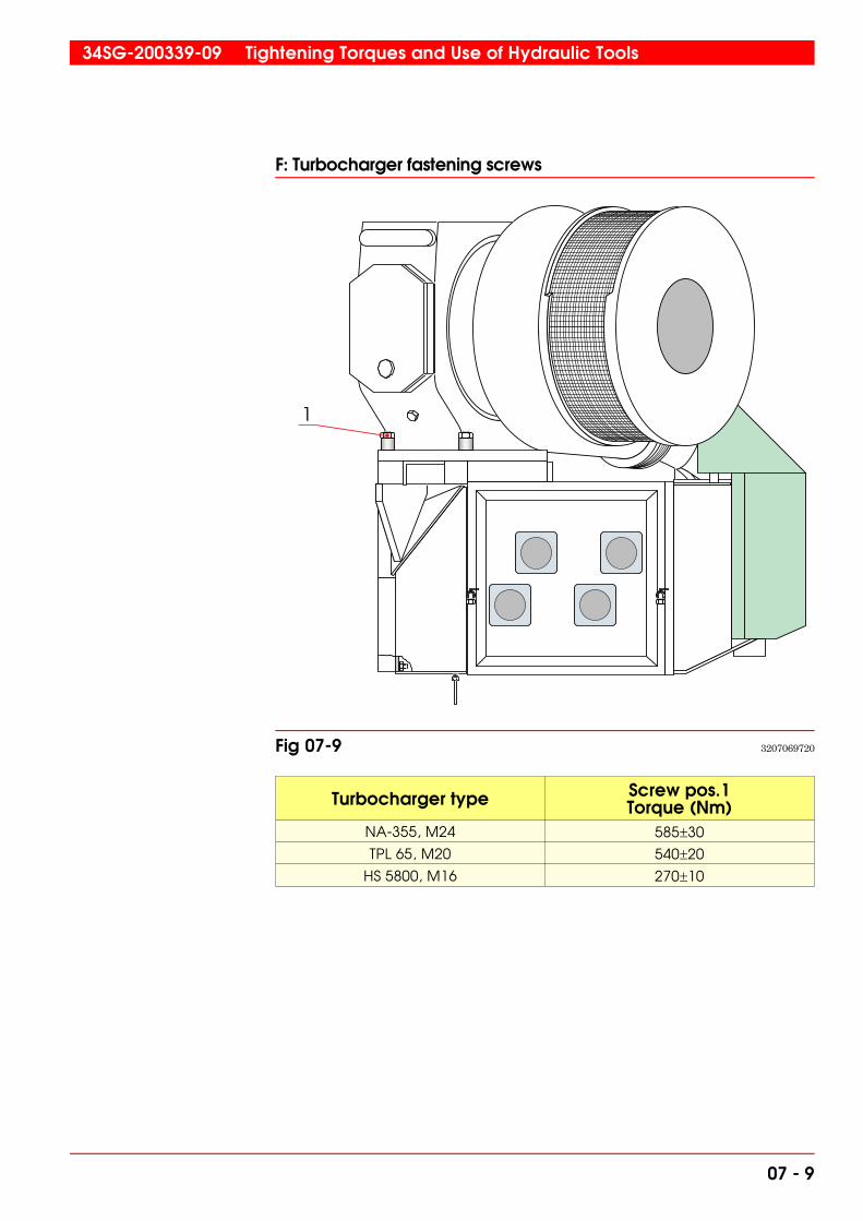
F: Turbocharger fastening screws
Turbocharger type Screw pos.1Torque (Nm)
NA-355, M24 585�30
TPL 65, M20 540�20
HS 5800, M16 270�10
1
Fig 07-9 3207069720
34SG-200339-09 Tightening Torques and Use of Hydraulic Tools
07 - 9
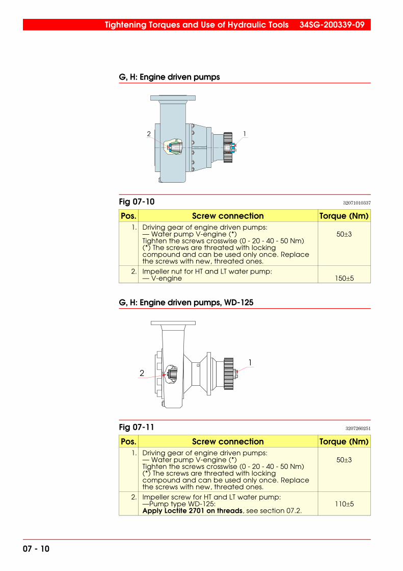
G, H: Engine driven pumps
Pos. Screw connection Torque (Nm)1. Driving gear of engine driven pumps:
— Water pump V-engine (*)Tighten the screws crosswise (0 - 20 - 40 - 50 Nm)(*) The screws are threated with lockingcompound and can be used only once. Replacethe screws with new, threated ones.
50�3
2. Impeller nut for HT and LT water pump:— V-engine 150�5
G, H: Engine driven pumps, WD-125
Pos. Screw connection Torque (Nm)1. Driving gear of engine driven pumps:
— Water pump V-engine (*)Tighten the screws crosswise (0 - 20 - 40 - 50 Nm)(*) The screws are threated with lockingcompound and can be used only once. Replacethe screws with new, threated ones.
50�3
2. Impeller screw for HT and LT water pump:—Pump type WD-125:Apply Loctite 2701 on threads, see section 07.2.
110�5
2 1
Fig 07-10 32071010337
21
Fig 07-11 3207260251
Tightening Torques and Use of Hydraulic Tools 34SG-200339-09
07 - 10
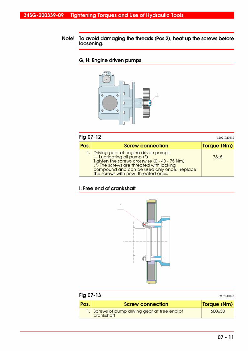
Note! To avoid damaging the threads (Pos.2), heat up the screws beforeloosening.
G, H: Engine driven pumps
Pos. Screw connection Torque (Nm)1. Driving gear of engine driven pumps:
— Lubricating oil pump (*)Tighten the screws crosswise (0 - 40 - 75 Nm)(*) The screws are threated with lockingcompound and can be used only once. Replacethe screws with new, threated ones.
75�5
I: Free end of crankshaft
Pos. Screw connection Torque (Nm)1. Screws of pump driving gear at free end of
crankshaft600�30
1
Fig 07-12 32071020337
1
Fig 07-13 3207649045
34SG-200339-09 Tightening Torques and Use of Hydraulic Tools
07 - 11

We recommend the use of torque measuring tools also when tighteningother screws and nuts. The following torques apply to screws of thestrength class 8.8; when oiled with lubricating oil or treated withLoctite.
Screw di-mension
Width across flatsof hexagon screws
(mm)
Key width ofhexagon socket
head screws (mm)
Torque(Nm) (kpm)
M8 13 6 23 2.3
M10 17 8 45 4.6
M12 19 10 80 8.1
M16 24 14 190 19.3
M20 30 17 370 37.5
M24 36 19 640 65.0
07.2 Use of locking fluid
When using locking fluid (Loctite), clean parts carefully in degreasingfluid and let then dry completely before applying locking fluid.
Tightening Torques and Use of Hydraulic Tools 34SG-200339-09
07 - 12

07.3 Hydraulically tightened connections
07.3.1 Tightening pressures for hydraulically tightened connections
Hydraulically tightened connections
Pos. Screw connectionMax. hydraulic pressure (bar) Hydraulic
cylindertightening loosening1. Cylinder head screws M56:
- outer diameter of cylinder liner 450 mm 500 5203V86B79
2. Main bearing screws M56 615 635 3V86B793. Thrust bearing screws M42 615 635 3V86B784. Lateral screws of main bearings and thrust
bearing M42615 635 3V86B78
5. Connecting rod screws :5a. M30 tightening in two steps
First stepSecond step
5b. M24 tightening in two stepsFirst step
Second step
300600
400750
620
770
3V86B186
2V86B201
6. Counterweight screws M42 600 620 3V86B787. Engine fastening screws M42 x) 3V86B78 8. Fastening screws M42 for balancing shaft
bearing bracket715 735 3V86B78
9. Intermediate gears M56 660 680 3V86B0150
x) Pos. 7 see installation instructions.
4V86B144
3V86B0150
3V86B135
4V86B02
9
1
5a
6
4
2
7
3
8
5b
Fig 07-14 3207979542
34SG-200339-09 Tightening Torques and Use of Hydraulic Tools
07 - 13

The stud bolts are tightened to the casting at the following torques:
Screw dimension Tightening torque (Nm)M56 Cylinder head 400�20
M56 Main Bearing 300�10
M42 and M48 x 3 200�10
M24 and M30 Connecting rod 100�10
Exception! Screws acc. to pos. 4 and 7. Pos. 4 see chapter 10, section 10.2.3.
Caution! The screws will be overloaded if the maximum hydraulic pressureis exceeded.It is recommended to change the screws if maximum hydraulicpressure is exceeded for some reason.
If it is impossible to turn the nuts, when the maximum hydraulicpressure is reached: check for corrosion in threads; check tool conditionand manometer error.
07.3.2 Filling, venting and control of the high pressurehydraulic tool set
The hydraulic tool set consists of a high pressure hand pump with anintegrated oil container, hoses fitted with quick-couplings and non-re-turn valves, cylinders and a pressure gauge mounted on the hand pumpbut not connected to the pressure side of the pump. The components are coupled in series with the pressure gauge being the lastcomponent thus securing that every cylinder is fed with the correct pressure. The non-return valves in the hoses are integrated with the quick-cou-plings and are opened by the pins located in the centre of the male andfemale parts. If these pins get worn the coupling must be replacedbecause of the risk of blocking.� In the high pressure hydraulic tool set it is recommended to use
a special hydraulic oil or in any case an oil with a viscosity of about2°E at 20°C.
� During the filling of the container of the high pressure pump it isrecommendable to couple the set according to scheme B, Fig 07-15.Before filling, open the release valve (2) and empty the cylinders(4) by pressing the piston and cylinder together. After that, drainthe oil and re-fill through the filling plug (1).
� After filling, vent the system by pressing in, with a finger, thecentre pin of the female part of the last quick-coupling, thecoupling being disconnected from the pressure gauge. Keep onpumping until airfree oil emerges from the coupling.
� Check the pressure gauge of the hydraulic tool set regularly. Forthis purpose a comparison pressure gauge is delivered. This
Tightening Torques and Use of Hydraulic Tools 34SG-200339-09
07 - 14
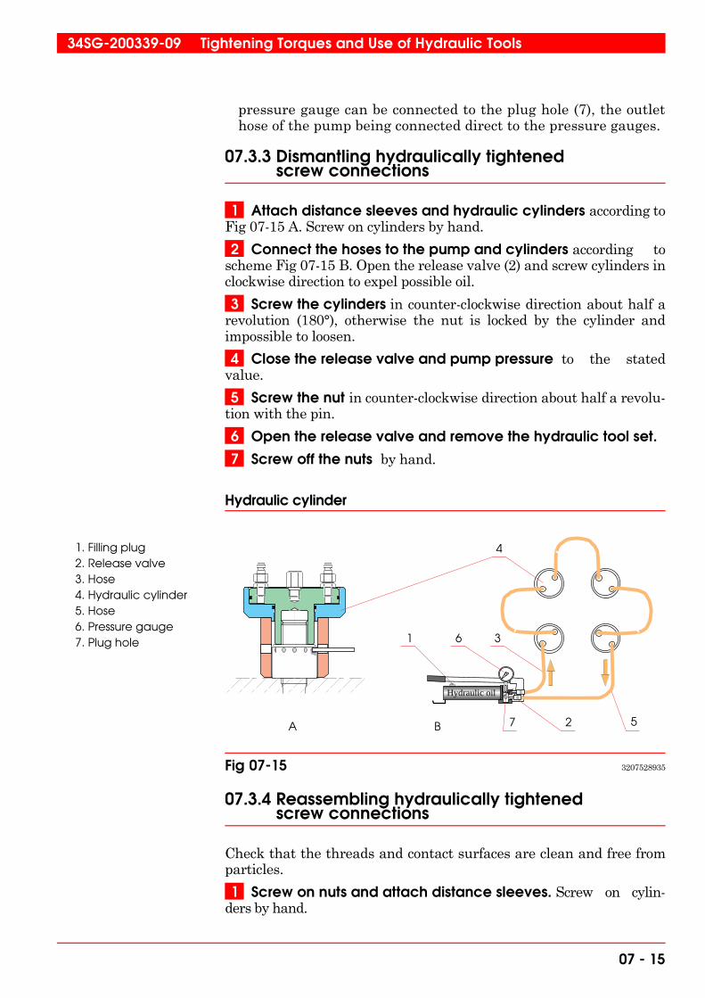
pressure gauge can be connected to the plug hole (7), the outlethose of the pump being connected direct to the pressure gauges.
07.3.3 Dismantling hydraulically tightenedscrew connections
1 Attach distance sleeves and hydraulic cylinders according toFig 07-15 A. Screw on cylinders by hand.
2 Connect the hoses to the pump and cylinders according toscheme Fig 07-15 B. Open the release valve (2) and screw cylinders inclockwise direction to expel possible oil.
3 Screw the cylinders in counter-clockwise direction about half arevolution (180°), otherwise the nut is locked by the cylinder andimpossible to loosen.
4 Close the release valve and pump pressure to the statedvalue.
5 Screw the nut in counter-clockwise direction about half a revolu-tion with the pin.
6 Open the release valve and remove the hydraulic tool set.
7 Screw off the nuts by hand.
Hydraulic cylinder
07.3.4 Reassembling hydraulically tightened screw connections
Check that the threads and contact surfaces are clean and free fromparticles.
1 Screw on nuts and attach distance sleeves. Screw on cylin-ders by hand.
Hydraulic oil
2 57
61 3
4
A B
1. Filling plug2. Release valve3. Hose4. Hydraulic cylinder5. Hose6. Pressure gauge7. Plug hole
Fig 07-15 3207528935
34SG-200339-09 Tightening Torques and Use of Hydraulic Tools
07 - 15

2 Connect the hoses to the pump and cylinders. Check thatthe release valve is open and screw the cylinders in clockwise directionto expel possible oil.
3 Close the release valve and pump pressure to the statedvalue.
4 Screw the nuts in a clockwise direction until in close contact withthe face. Use the pin intended for this purpose and tighten the nut asmuch as possible without breaking the pin. Keep the pressure constantat the stated value.
5 Open the release valve and remove the hydraulic tool set.
To ensure that the nut will be properly tightened, the pressure can beraised in two steps. Pump the pressure to 300 bar and screw the nut in aclockwise direction until in close contact with the face. Increase thepressure further to the stated pressure, and screw the nut until in closecontact with the face again. This time the nut should move just a limitedangle but approximately the same angle for all nuts of the same kind.
Note! Ensure that all screw connections that have been opened are pro-perly tightened and locked, if necessary, before the engine is started.
07.3.5 Hydraulic tool for connecting rod screws
Hydraulic tool, hose connection and tool section
Hydraulic oil
Fig 07-16 3207889542
Tightening Torques and Use of Hydraulic Tools 34SG-200339-09
07 - 16

07.4 Use of hydraulic extractor cylinder
For some power demanding operations a hydraulic extractor cylinderis used. In connection with this cylinder, the hydraulic high pressurehand pump is utilized, coupling scheme acc. to Fig 07-17.
Hydraulic extractor cylinder
According to the design of the cylinder, the outer cylinder (1) must notbe loaded, but the force is created between the surfaces A and B. The piston is prevented from running out of the cylinder by anexpansion ring (2). The strength of this ring is limited, and it isrecommended to be careful when operating at the end of the stroke. The effective area of the piston is 14.42 cm2 which gives the followingrelation between pressure and force.
Hydraulic oil
2
A
B1
1. Hydraulic cylinder2. Expansion ring
Fig 07-17 3207538935
34SG-200339-09 Tightening Torques and Use of Hydraulic Tools
07 - 17

Relation between pressure and force for hydraulic extractor cylinder 3V83E61
07.5 Low pressure pump for lifting purposes in the crankcase
A special low pressure pump (150 bar) is delivered for lifting tools usedin the crankcase. Normal engine oil, which is used in the enginelubricating system (sump) must be used in this pump because the drainoil from the tools is led to the sump of the engine.
2000 4000 6000 8000 10000 12000
20000 40000 60000 80000 100000 120000
200
400
600
800
Bar
kp
N
Max pressure
Fig 07-18 3207548935
Tightening Torques and Use of Hydraulic Tools 34SG-200339-09
07 - 18

08. Trouble shooting
08.1 General
The engine should be maintained according to the schedule in chapter04. Some possible operating troubles may though require promptaction. The engine operators should therefore aquire knowledge of thischapter for action when needed. The contents of this text shall be used as guidelines only as thismanual do not necessarily exactly describe the actual installation.
Warning! To avoid personal and/or property injury, the local electrical instal-lation safety precautions and chapter 23 as well as appendix 00Ain this manual must be followed during all maintenance.
08.2 Trouble shooting based on messages
As the engines mainly operates in multi-engine installations thischapter deals with two categories of error messages:
Messages in the engine automation (WECS) safety process:• Engine shutdown (SHD)• Load reduction (LRED)• Alarm (ALM)• Start blocking (STB)• Sensor failure (SF)
Messages in the plant automation (PLC) safety process:• Engine shutdown (SHD)• Load reduction (LRED)• Alarm (ALM)• Start blocking (STB)• Sensor failure (SF)
34SG-200414-04 Operating Troubles
08 - 1

Shutdowns (SHD) messages by WECSCode Message Reason Action
KDU0_1E001SDI SHD, 24 V DC powerfailure, KDU1
Power supply failureto KDU
Check acc. to Fig 08-10 Power supplyfailure to KDU
KDU0_1E002SDI SHD, 24 V DC powerfailure, KDU2
Power supply failureto KDU
Check acc. to Fig 08-10 Power supplyfailure to KDU
DCU0_1E001SDI SHD, CAN-bus failureDCU 1
MCU unable tocommunicate with
DCU 1 over CAN bus
DCU CAN LED blinking and power LEDlit. Check the power supply for theDCU, if the power supply voltage is
within the limits (24 VDC +/- 4), checkthe CAN according to the Fig 08-13.
Replace DCU
DCU0_1E002SDI SHD, CAN-bus failureDCU 2
MCU unable tocommunicate with
DCU 2 over CAN bus
DCU CAN LED blinking and power LEDlit. Check the power supply for theDCU, if the power supply voltage is
within the limits (24 VDC +/- 4), checkthe CAN according to the Fig 08-13.
Replace DCU
DCU0_1E003SDI SHD, CAN-bus failureDCU 3
MCU unable tocommunicate with
DCU 3 over CAN bus
DCU CAN LED blinking and power LEDlit. Check the power supply for theDCU, if the power supply voltage is
within the limits (24 VDC +/- 4), checkthe CAN according to the Fig 08-13.
Replace DCU
CCU0_1E3nnSDI SHD, CAN-bus failure,CCUn
CAN communicationbus failure to CCU
Check acc. to Fig 08-11 CAN-busfailure CCU
SOB0_1E052SDH SHD, Dev. betw.reference and actual
speed
Internal speedcontroller referencevalue deviates from
the actual speed
Check the fuel supply, too big loadstep
SOB0_1E050SDH SHD, Dev. betweenkW-ref. and actual
load *)
Too high deviationbetween actual
load and setpoint,too high load
request. Air/Fuel ratioincorrect
Please contact nearest WärtsiläService office
CCU0_1E0nnSDI SHD, EMG mode,24VDC power supply
failure, CCUn
24 VDC powersupply failure to CCU
Check acc. to Fig 08-9. Power supplyfailure to CCU
SCX0_1E055SDI SHD, EMG mode,Degassing failure
Gas pressure in themain gas line after
engine stop
Check the ventilation valve operationand the shut-off valve operation on
the gas regulating unit
SOB0_1E001SDH SHD, EMG mode,Overload
Overload 110 % ofrated load
Check load demands
SOB0_1S001SDH SHD, EMG mode,Overspeed from
engine speedpickup, ST173
Measured(secondary) speedover rated speed,
115 %
Check the event list for triggeringcause (grid connection status signals)
SOB0_1H001SDH SHD, EMG mode,Overspeed from
rotary encoder, ST175
Measured (primary)speed over rated
speed, 115 %
Check the event list for triggeringcause (grid connection status signals)
CCU0_1E2nnSDI SHD, EMG mode,Speed / TDC ratio
failure, CCUn
Speed pulses missingfrom rotary encoder
Check possible wiring earth faults andacc. to Fig 08-5. Rotary encoder
failure
*) only in kW control
Operating Troubles 34SG-200414-04
08 - 2

Shutdowns (SHD) messages by WECSCode Message Reason Action
SOB0_1E004SDI SHD, Engine loadsensor failure, UT793
Sensor broken orwiring fault (broken
or loose connections)
Check acc. to Fig 08-4 4-20 mA sensorfailure MCU
SCX0_1E005SDI SHD, Engine statusfrom WECS,
Emergency mode
Emergency modeactive
Check the separately informedemergency cause (primary)
SCX0_1E004SDI SHD, Engine statusfrom WECS,
Shutdown mode
Shutdown modeactive
Check the separately informedshutdown cause (primary)
SCX0_1F000SDH SHD, Heavy knocking Cylinder overload,Leaking main gasvalve, Poor gas
quality,Injection/ignition
timing error
Check main gas valve, Checkencoder position, Perform cylinder
balancing
SOB0_1P001SDH SHD, High crankcasepressure, PT700
Obstraction incrankcase breathing
line, Exhaust gasblow by, Bearing
seizure
Check crankcase breathing line,check bearing temperatures, inspect
cylinder liners
SOC0_1T100SDH SHD, High cylinderliner temperature
Continuous lightknocking, Exhaust
gas blow-by, Pistonseizure, High coolingwater temperature
Check ignition system, checkcalibration of knock detection
system, check main gas valve, checkcooling water system, Visually inspect
piston and cylinder liner
SNA0_1T100SDH SHD, High dev. exh.gas temp.
cyl./average
Cylinder exhaust gastemperature is
significantly higherthan engine average
See cylinder combustion failure checklists in section 08.2.1.
SNA0_1T000SDH SHD, High exhaustgas temperature
Big load steps,Leaking main gasvalve, Incorrect
Air/Fuel ratio, Burnedexhaust gas valves
See cylinder combustion failure checklists in section 08.2.1.
BAG0_1T000SDH SHD, High generatorbearing temperature
Low lube oil level,bearing seizure
Check lube oil level, checkalignment, Visually inspect the
bearing
BAG0_1T006SDH SHD, High generatorcold cooling airtemp., TE758 *)
High generatorcooling watertemperature
Check external cooling system
BAG0_1T007SDH SHD, High generatorhot cooling air temp.,
TE759 *)
High generatorcooling watertemperature
Check external cooling system
BAG0_1T001SDH SHD, High generatorwinding temperature,
L1
High windingtemperature, due tohigh reactive load,overcurrent, high
harmonics, cloggedfilters or high
ambient temperature
Check reactive loads and currents(reduce load), Clean filters and
ensure that ventilation is on
*) only water cooled generators
34SG-200414-04 Operating Troubles
08 - 3

Shutdowns (SHD) messages by WECSCode Message Reason Action
BAG0_1T002SDH SHD, High generatorwinding temperature,
L2
High windingtemperature, due tohigh reactive load,overcurrent, high
harmonics, cloggedfilters or high
ambient temperature
Check reactive loads and currents(reduce load), Clean filters and
ensure that ventilation is on
BAG0_1T003SDH SHD, High generatorwinding temperature,
L3
High windingtemperature, due tohigh reactive load,overcurrent, high
harmonics, cloggedfilters or high
ambient temperature
Check reactive loads and currents(reduce load), Clean filters and
ensure that ventilation is on
SOC0_1T000SDH SHD, High mainbearing temperature
Low lube oil flow,main bearing seizure
Check lube oil pump and system,Check main bearing temperature
trends, Visualy inspect the bearing
SOB0_1E055SDH SHD, High speed dev.betw. pickup and
rotary enc.
Deviation in speedmeasured by MCU
and CCUs
Check acc. to Fig 08-6 inductivesensor failure and 4-20 mA signal from
OTM to MCU. Check the Fig 08-5.Rotary encoder failure.
SNA0_1T100SDL SHD, Low dev. exh.gas temp.
cyl./average
Cylinder exhaust gastemperature is
significantly lowerthan engine average
See cylinder combustion failure checklists in section 08.2.1.
SQA0_1P008SDL SHD, Low lube oilpressure, inlet, PT201
Contaminated lubeoil filter, Low lube oil
level, Cloggedcooling system,Broken pipes,
Foaming
Check diff pressure over lube oil filter,Check lube oil level, Check coolingsystem, Check pipe system, Check
lube oil sump for foaming
SQA0_1P008SDI SHD, Lube oil pressuresensor failure, PT201
Sensor broken orwiring fault (broken
or loose connections)
Check acc. to Fig 08-3 4-20 mA sensorfailure
SCX0_1E059SDH SHD, Main fuelinjection duration
max. time
Engine is not gettingenough fuel tomaintain speed
and/or load
Check the gas flow and pressuresand the gas regulating unit
SCX0_1E056SDH SHD, Max idle timeexceeded
The engine has beenrunning idle for more
than 5 minutes
Idle running for more than 5 minutes isnot allowed. Check synchronisation
circuits
SNA0_1T000SDL SHD, Min exhaust gastemp. not reached
Minimum requiredcombustion
temperature duringstart not reached
If the same shutdown occursrepeatedly during a series of start
attempts.
SOB0_1E054SDL SHD, Nominal speednot reached
Expectedacceleration to
nominal speed notachieved, Some
cylinders did not getcorrect air/fuel
mixture
Check that the main gas pressure isclose to the setpoint. If the same
shutdown occurs repeatedly during aseries of start attempts.
SOB0_1E058SDL SHD, Too low enginespeed at current
load *)
Too high load atcurrent speed,
overload
Check speed and load demands
*) only Compset/Pumpset installations
Operating Troubles 34SG-200414-04
08 - 4

Alarm (ALM) messages by WECSCode Message Reason Action
SNA0_1T1nnDAH ALM, Cyl. disableddue to temp. dev.,
cyl n
Combustion failureof cylinder. Cylinderinjection is disabled
See cylinder combustion failure checklists in section 08.2.1.
SOB0_1E050AH ALM, Dev. betweenkW-ref. and actual
load *)
Too high deviationbetween actual
load and setpoint,too high load
request. Air/Fuel ratioincorrect
Please contact nearest WärtsiläService office
SCX0_1E062ALI ALM, Failed startattempt
Start attempt failedfor initial startpreparations
Check function of starter motors,Check fuel supply, Check start air
supply
BAG0_1L001ALI ALM, Generatorwater leakage, LS756
**)
Generator coolingwater circuit leakage
Visual check of cooling system to beperformed
SNB0_1T004AH ALM, High charge airtemperature, TE622
High ambienttemperature, High LTwater temperature,CA cooler blow-by,Contaminated CA
coolers
Check cooling system, Checkdifference between LT and CA
temperature, Check CA diff pressure
SOB0_1P001AH ALM, High crankcasepressure, PT700
Obstraction incrankcase breathing
line, Exhaust gasblow by, Bearing
seizure
Stop the engine. Check crankcasebreathing line, check bearing
temperatures, inspect cylinder liners
SNA0_1T100AH ALM, High dev. exh.gas temp.
cyl./average
Cylinder exhaust gastemperature is
significantly higherthan engine average
See cylinder combustion failure checklists in section 08.2.1.
SNA0_1T0nnAH ALM, High exhaustgas temperature, cyl
n
Big load steps,Leaking main gasvalve, Incorrect
Air/Fuel ratio, Burnedexhaust gas valves
See cylinder combustion failure checklists in section 08.2.1.
BAG0_1T004AH ALM, High gen.bearing drive end
temp., TE751
Low lube oil level,bearing seizure
Check lube oil level, Check generatorventilation
BAG0_1T005AH ALM, High gen.bearing non-driveend temp., TE752
Low lube oil level,bearing seizure
Check lube oil level, Check generatorventilation
BAG0_1T006AH ALM, High generatorcold cooling airtemp., TE758 **)
High generatorcooling watertemperature
Check external cooling system
BAG0_1T007AH ALM, High generatorhot cooling air temp.,
TE759 **)
High generatorcooling watertemperature
Check external cooling system
BAG0_1T001AH ALM, High generatorwinding temperature
L1
High windingtemperature, due tohigh reactive load,overcurrent, high
harmonics, cloggedfilters or high
ambient temperature
Check reactive loads and currents(reduce load), Clean filters and
ensure that ventilation is on
*) only in kW control**) only water cooled generators
34SG-200414-04 Operating Troubles
08 - 5

Alarm (ALM) messages by WECSCode Message Reason Action
BAG0_1T002AH ALM, High generatorwinding temperature
L2
High windingtemperature, due tohigh reactive load,overcurrent, high
harmonics, cloggedfilters or high
ambient temperature
Check reactive loads and currents(reduce load), Clean filters and
ensure that ventilation is on
BAG0_1T003AH ALM, High generatorwinding temperature
L3
High windingtemperature, due tohigh reactive load,overcurrent, high
harmonics, cloggedfilters or high
ambient temperature
Check reactive loads and currents(reduce load), Clean filters and
ensure that ventilation is on
SVH0_1T013AH ALM, High HT watertemperature, TE402
Insufficient cooling,Low cooling water
flow
Check cooling system
CCU0_1T0nnAH ALM, High internaltemp. CCUn
Internal temperatureof CCU too high
Check engine room ventilation
DCU0_1T001AH ALM, High internaltemperature, DCU 1,
TE831
Internal temperatureof DCU too high
Check engine room ventilation
DCU0_1T002AH ALM, High internaltemperature, DCU 2,
TE832
Internal temperatureof DCU too high
Check engine room ventilation
DCU0_1T003AH ALM, High internaltemperature, DCU 3,
TE833
Internal temperatureof DCU too high
Check engine room ventilation
KDU0_1T001AH ALM, High internaltemperature, KDU1
Internal temperatureof KDU too high
Check engine room ventilation
KDU0_1T002AH ALM, High internaltemperature, KDU2
Internal temperatureof KDU too high
Check engine room ventilation
SMU0_1T102AH ALM, High internaltemperature, SMU 1-
2, TE841
Internal temperatureof SMU too high
Check engine room ventilation
SMU0_1T103AH ALM, High internaltemperature, SMU 1-
3, TE842
Internal temperatureof SMU too high
Check engine room ventilation
SMU0_1T202AH ALM, High internaltemperature, SMU 2-
2, TE843
Internal temperatureof SMU too high
Check engine room ventilation
SMU0_1T302AH ALM, High internaltemperature, SMU 3-
2, TE844
Internal temperatureof SMU too high
Check engine room ventilation
SOC0_1T1nnAH ALM, High linertemp., cylinder n,
average
Continuous lightknocking, Exhaust
gas blow-by, Pistonseizure, High coolingwater temperature
Check ignition system, checkcalibration of knock detection
system, check main gas valve, checkcooling water system, check piston
and cylinder liner
SQA0_1T003AH ALM, High lube oiltemperature, inlet,
TE201
Lube oil coolerclogged, Cooling
water temperaturetoo high
Check lube oil cooler, check coolingwater temperature
Operating Troubles 34SG-200414-04
08 - 6

Alarm (ALM) messages by WECSCode Message Reason Action
SZA0_1P001ALI ALM, High main gaspressure deviation
Main gas pressuredeviates from
setpoint
Check calibration of gas regulatingunit
SZA0_1P002ALI ALM, High PCC gaspressure deviation *)
Pilot gas pressuredeviates from
setpoint
Check calibration of gas regulatingunit
SCX0_1E060AH ALM, High press.difference main gas /
charge air
Too high gaspressure compared
to charge air pressure
Engine parameters need to beoptimized
SOC0_1T0nnAH ALM, Hightemperature, main
bearing n
Contaminated oil,Low lube oil flow,
main bearing seizure
Regularly oil sample tests, Check lubeoil pump and system, Check main
bearing temperature trends
KDU0_1E101ALI ALM, KDU CANfailure, KDU1
CAN communicationbus failure to KDU
Check acc. to Fig 08-12 CAN busfailure KDU
KDU0_1E102ALI ALM, KDU CANfailure, KDU2
CAN communicationbus failure to KDU
Check acc. to Fig 08-12 CAN busfailure KDU
KDU0_1E301ALI ALM, KDU failure,KDU1
Knock values are notupdated
Check that the rotary switches areaccording to the engine electrical
drawings
KDU0_1E302ALI ALM, KDU failure,KDU2
Knock values are notupdated
Check that the rotary switches areaccording to the engine electrical
drawings
SCX0_1F0nnSF ALM, Knock sensorfailure, cylinder n
Self diagnostics ofknock detection
system indicates toolow signal level
Check valve clearances of cylinderhead, Check sensor acc. To Fig 08-8
Knock sensor failure
SOB0_1E057ALI ALM, kW control trip Too high frequencydeviation fromnominal gridfrequency
Engine will enter speed droop control
STA0_1P005AL ALM, Low control airpressure, PT311
Low control airpressure
Check control air supply for leakages
SNA0_1T100AL ALM, Low dev. exh.gas temp.
cyl./average
Cylinder exhaust gastemperature is
significantly lowerthan engine average
Refer to cylinder combustion failurecheck lists in section 08.2.1.
SVH0_1P003AL ALM, Low HT waterpressure, PT401
Low cooling waterlevel, Obstraction inpump or suction line,
Exhaust gases incooling system
Check cooling water level, Checkcooling water lines, Check cylinder
gaskets
SVH0_1T006AL ALM, Low HT watertemperature, inlet,
TE401
Insufficient pre-heating before start-
up, Thermostaticvalve failure
Check pre-heater, Checkthermostatic valve
SVL0_1P003AL ALM, Low LT waterpressure inlet, PT451
Low cooling waterlevel, Obstraction inpump or suction line
Check cooling water level, Checkcooling water lines
SQA0_1L001AL ALM, Low lube oillevel, LS204
Lube oil level belowlow alarm limit
Check the lube oil level
*) only dual gas line system
34SG-200414-04 Operating Troubles
08 - 7
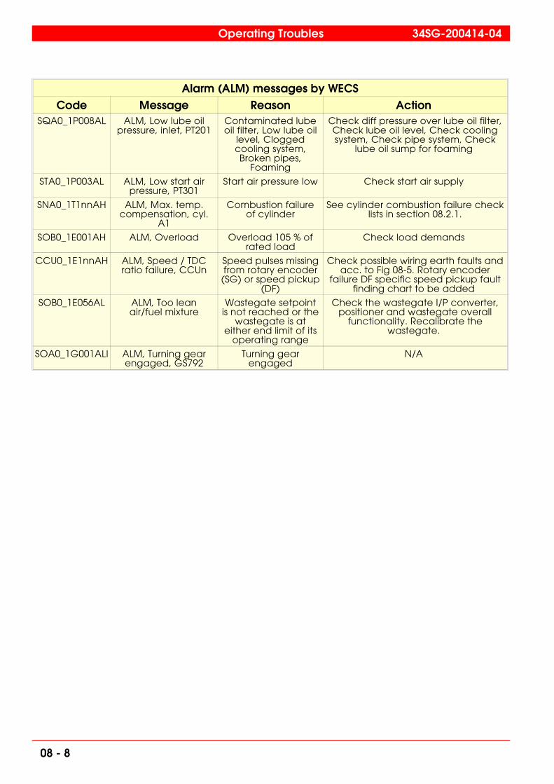
Alarm (ALM) messages by WECSCode Message Reason Action
SQA0_1P008AL ALM, Low lube oilpressure, inlet, PT201
Contaminated lubeoil filter, Low lube oil
level, Cloggedcooling system,Broken pipes,
Foaming
Check diff pressure over lube oil filter,Check lube oil level, Check coolingsystem, Check pipe system, Check
lube oil sump for foaming
STA0_1P003AL ALM, Low start airpressure, PT301
Start air pressure low Check start air supply
SNA0_1T1nnAH ALM, Max. temp.compensation, cyl.
A1
Combustion failureof cylinder
See cylinder combustion failure checklists in section 08.2.1.
SOB0_1E001AH ALM, Overload Overload 105 % ofrated load
Check load demands
CCU0_1E1nnAH ALM, Speed / TDCratio failure, CCUn
Speed pulses missingfrom rotary encoder(SG) or speed pickup
(DF)
Check possible wiring earth faults andacc. to Fig 08-5. Rotary encoder
failure DF specific speed pickup faultfinding chart to be added
SOB0_1E056AL ALM, Too leanair/fuel mixture
Wastegate setpointis not reached or the
wastegate is ateither end limit of its
operating range
Check the wastegate I/P converter,positioner and wastegate overall
functionality. Recalibrate thewastegate.
SOA0_1G001ALI ALM, Turning gearengaged, GS792
Turning gearengaged
N/A
Operating Troubles 34SG-200414-04
08 - 8
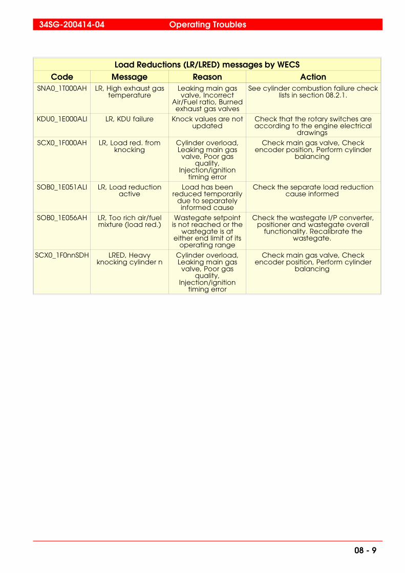
Load Reductions (LR/LRED) messages by WECSCode Message Reason Action
SNA0_1T000AH LR, High exhaust gastemperature
Leaking main gasvalve, Incorrect
Air/Fuel ratio, Burnedexhaust gas valves
See cylinder combustion failure checklists in section 08.2.1.
KDU0_1E000ALI LR, KDU failure Knock values are notupdated
Check that the rotary switches areaccording to the engine electrical
drawings
SCX0_1F000AH LR, Load red. fromknocking
Cylinder overload,Leaking main gasvalve, Poor gas
quality,Injection/ignition
timing error
Check main gas valve, Checkencoder position, Perform cylinder
balancing
SOB0_1E051ALI LR, Load reductionactive
Load has beenreduced temporarily
due to separatelyinformed cause
Check the separate load reductioncause informed
SOB0_1E056AH LR, Too rich air/fuelmixture (load red.)
Wastegate setpointis not reached or the
wastegate is ateither end limit of its
operating range
Check the wastegate I/P converter,positioner and wastegate overall
functionality. Recalibrate thewastegate.
SCX0_1F0nnSDH LRED, Heavyknocking cylinder n
Cylinder overload,Leaking main gasvalve, Poor gas
quality,Injection/ignition
timing error
Check main gas valve, Checkencoder position, Perform cylinder
balancing
34SG-200414-04 Operating Troubles
08 - 9

Start Blocks (STB) messages by WECSCode Message Reason Action
CCU0_1E032SBL STB, CCUconfiguration fault
CCU configurationmissmatch
Check that the rotary switches areaccording to the engine electrical
drawings
CCU0_1E031SBL STB, CCU powersupply failure
CCU supply voltageis too low (below 18
VDC)
Check the CCU supply voltage acc.to Fig 08-9. Power supply failure
SCX0_1E052SBL STB, Communicationfault WECS / PLC
The MCU has notrecevied project
constants from thePLC (Profibus index
53 received).
Check the profibus communication(cabling and terminating resistors)
SOB0_1S002SBL STB, Engine speedfrom redundant pick-
up, ST173
Engine speed is notzero
Wait until the engine has stoppedcompletely
SOB0_1H001SBL STB, Engine speedfrom rotary encoder,
ST175
Engine speed is notzero
Wait until the engine has stoppedcompletely
SVH0_1T006SBL STB, Low HT watertemperature, TE401
HT watertemperature too low
for starting
Pre-heat the engine
SQA0_1L001SBL STB, Low lube oillevel, LS204
Lube oil level too low Check the lube oil level
SQA0_1P008SBL STB, Low lube oilpressure engine inlet,
PT201
Pre-lubricationpressure is too low
Check the pre-lubrication pump andadjust pressure if necessary
STA0_1P003SBL STB, Low starting airpressure, PT301
Starting air pressure istoo low
Check the starting air supply
SOA0_1G001SBL STB, Turning gearengaged, GS792
Turning gear isengaged
Disengage the turning gear
Operating Troubles 34SG-200414-04
08 - 10

Sensor Failure (SF) messages by WECSCode Message Reason Action
SVL0_1P003SF SF, LT water pressure,inlet, PT451
Sensor broken orwiring fault (broken
or loose connections)
Check acc. to Fig 08-3. 4-20 mAsensor failure
NGA0_1T001SF SF, Air temp., TC Ainlet, TE600A
Sensor broken orwiring fault (broken
or loose connections)
Check acc. to Fig 08-1. PT-100 sensorfailure
NGA0_1T002SF SF, Air temp., TC Binlet, TE600B
Sensor broken orwiring fault (broken
or loose connections)
Check acc. to Fig 08-1. PT-100 sensorfailure
SNB0_1P007SF SF, Charge airpressure, CAC outlet,
PT622
Sensor broken orwiring fault (broken
or loose connections)
Check acc. to Fig 08-4 4-20 mA sensorfailure MCU
SNB0_1T004SF SF, Charge air temp.,CAC outlet, TE622
Sensor broken orwiring fault (broken
or loose connections)
Check acc. to Fig 08-1 PT-100 sensorfailure
STA0_1P005SF SF, Control airpressure, PT311
Sensor broken orwiring fault (broken
or loose connections)
Check acc. to Fig 08-3. 4-20 mAsensor failure
SOB0_1P001SF SF, Crankcasepressure, PT700
Sensor broken orwiring fault (broken
or loose connections)
Check acc. to Fig 08-3. 4-20 mAsensor failure or Fig 08-4 4-20 mA
sensor failure MCU
SOC0_1T1nnSF SF, Cylinder n linertemp., average
Sensor broken orwiring fault (broken
or loose connections)
Check acc. to Fig 08-2.Thermocouple sensor failure
SOB0_1E004SF SF, Engine load,UT793
Sensor broken orwiring fault (broken
or loose connections)
Check acc. to Fig 08-4 4-20 mA sensorfailure MCU
SOB0_1S001SF SF, Engine speed,redundant pick-up,
ST173
Sensor broken orwiring fault (broken
or loose connections)
Check acc. to Fig 08-6. inductivesensor failure and 4-20 mA signal from
OTM to MCU
NHA0_1T002SF SF, Exh. gas temp., TCB outlet, TE527
Sensor broken orwiring fault (broken
or loose connections)
Check acc. to Fig 08-2.Thermocouple sensor failure
NHA0_1T001SF SF, Exh. gas temp.,turbo charger A
outlet, TE517
Sensor broken orwiring fault (broken
or loose connections)
Check acc. to Fig 08-2.Thermocouple sensor failure
SNA0_1T0nnSF SF, Exh. gastemp.,,cylinder n
average
Sensor broken orwiring fault (broken
or loose connections)
Check acc. to Fig 08-2.Thermocouple sensor failure
BAG0_1T004SF SF, Generatorbearing temp., drive
end, TE751
Sensor broken orwiring fault (broken
or loose connections)
Check acc. to Fig 08-1. PT-100 sensorfailure
BAG0_1T005SF SF, Generatorbearing temp., non-
drive end, TE752
Sensor broken orwiring fault (broken
or loose connections)
Check acc. to Fig 08-1. PT-100 sensorfailure
BAG0_1T006SF SF, Generator coldcooling air, TE758
Sensor broken orwiring fault (broken
or loose connections)
Check acc. to Fig 08-1. PT-100 sensorfailure
BAG0_1T007SF SF, Generator hotcooling air, TE759
Sensor broken orwiring fault (broken
or loose connections)
Check acc. to Fig 08-1. PT-100 sensorfailure
34SG-200414-04 Operating Troubles
08 - 11

Sensor Failure (SF) messages by WECSCode Message Reason Action
BAG0_1T001SF SF, Generatorwinding temp., L1,
TE753
Sensor broken orwiring fault (broken
or loose connections)
Check acc. to Fig 08-1. PT-100 sensorfailure
BAG0_1T002SF SF, Generatorwinding temp., L2,
TE754
Sensor broken orwiring fault (broken
or loose connections)
Check acc. to Fig 08-1. PT-100 sensorfailure
BAG0_1T003SF SF, Generatorwinding temp., L3,
TE755
Sensor broken orwiring fault (broken
or loose connections)
Check acc. to Fig 08-1. PT-100 sensorfailure
SVH0_1P003SF SF, HT water pressure,inlet, PT401
Sensor broken orwiring fault (broken
or loose connections)
Check acc. to Fig 08-3. 4-20 mAsensor failure
SVH0_1T006SF SF, HT water temp.,inlet, TE401
Sensor broken orwiring fault (broken
or loose connections)
Check acc. to Fig 08-1. PT-100 sensorfailure
SVH0_1T013SF SF, HT water temp.,outlet, TE402
Sensor broken orwiring fault (broken
or loose connections)
Check acc. to Fig 08-1. PT-100 sensorfailure
SVL0_1T005SF SF, LT water temp.,inlet, TE451
Sensor broken orwiring fault (broken
or loose connections)
Check acc. to Fig 08-1. PT-100 sensorfailure
SVL0_1T006SF SF, LT water temp.,outlet, TE452
Sensor broken orwiring fault (broken
or loose connections)
Check acc. to Fig 08-1. PT-100 sensorfailure
SQA0_1P008SF SF, Lube oil pressure,inlet, PT201
Sensor broken orwiring fault (broken
or loose connections)
Check acc. to Fig 08-3. 4-20 mAsensor failure
SQA0_1T003SF SF, Lube oil temp.,inlet, TE201
Sensor broken orwiring fault (broken
or loose connections)
Check acc. to Fig 08-1. PT-100 sensorfailure
SQA0_1T004SF SF, Lube oil temp.,outlet, TE202
Sensor broken orwiring fault (broken
or loose connections)
Check acc. to Fig 08-1. PT-100 sensorfailure
SOC0_1T0nnSF SF, Main bearing ntemperature
Sensor broken orwiring fault (broken
or loose connections)
Check acc. to Fig 08-2.Thermocouple sensor failure
SZA0_1P001SF SF, Main gas pressure,PT901
Sensor broken orwiring fault (broken
or loose connections)
Check acc. to Fig 08-4 4-20 mA sensorfailure MCU
SZA0_1P002SF SF, PCC gas pressure,PT911 *)
Sensor broken orwiring fault (broken
or loose connections)
Check acc. to Fig 08-4 4-20 mA sensorfailure MCU
STA0_1P003SF SF, Starting airpressure, PT301
Sensor broken orwiring fault (broken
or loose connections)
Check acc. to Fig 08-3. 4-20 mAsensor failure
DCU0_1T001SF SF, Temp. in DCU1,TE831
Internal temperaturemeasurement of I/O
board broken
Replace I/O board
DCU0_1T002SF SF, Temp. in DCU2,TE832
Internal temperaturemeasurement of I/O
board broken
Replace I/O board
*) only dual gas line system
Operating Troubles 34SG-200414-04
08 - 12

Sensor Failure (SF) messages by WECSCode Message Reason Action
DCU0_1T003SF SF, Temp. in DCU3,TE833
Internal temperaturemeasurement of I/O
board broken
Replace I/O board
SMU0_1T102SF SF, Temp. in SMU1-2,TE841
Internal temperaturemeasurement of I/O
board broken
Replace I/O board
SMU0_1T103SF SF, Temp. in SMU1-3,TE842
Internal temperaturemeasurement of I/O
board broken
Replace I/O board
SMU0_1T202SF SF, Temp. in SMU2-2,TE843
Internal temperaturemeasurement of I/O
board broken
Replace I/O board
SMU0_1T302SF SF, Temp. in SMU3-2,TE844
Internal temperaturemeasurement of I/O
board broken
Replace I/O board
SOB0_1S002SF SF, Turbo charger Aspeed, SE518
Sensor broken orwiring fault (broken
or loose connections)
Check acc. to Fig 08-7. Magneticpickup sensor failure
SOB0_1S003SF SF, Turbo charger Bspeed, SE528
Sensor broken orwiring fault (broken
or loose connections)
Check acc. to Fig 08-7. Magneticpickup sensor failure
SOA0_1G001SF SF, Turning gearengaged, GS792
Sensor broken orwiring fault (broken
or loose connections)
N/A
34SG-200414-04 Operating Troubles
08 - 13

Status/Events messages by WECSCode Message Reason Action
SCX0_1E051INF Communicationrestarted
Profibuscommunication
processor is restarted
N/A
SCX0_1E006INF Engine ready to start,from WECS
Engine ready tostart, startblocks are
cleared
n/a
SCX0_1E003INF Engine status fromWECS, Run mode
Run mode active n/a
SCX0_1E002INF Engine status fromWECS, Start mode
Start mode active n/a
SCX0_1E001INF Engine status fromWECS, Stop mode
Stop mode active n/a
SCX0_1E058INF External emergencystop order, from WECS
Emergency stoporder active,
activated by engineexternal system.
Safety relayactivated
n/a
SCX0_1E057INF External stop order,from WECS
Stop order active,activated by engine
external system
n/a
MCU0_1E101INF MCU restarted MCU restarted isactivated when
power gets belowthe data limit or if
the processor boardis manually reset
If this message occurs during normalrunning check the DC/DC converter
(U1) input (24 VDC) and outputvoltages (5 VDC). Replace theDC/DC converter if the output
voltage is not 5 VDC. If the DC/DCconverter is ok then likely cause is the
5 VDC board failure or processorboard failure of the MCU. The 5 VDCboard and MCU are to be replaced if
faulty.
SCX0_1E050INF Profibus index 53received
Acknowledges thatthe MCU has
recevied projectconstants from the
PLC, i.e the profibuscommunication is in
order. This eventshould occur
immediately afterthe "MCU restarted"
event.
If this event is not occuring after "MCUrestarted" check the profibuscommunication (cabling and
terminating resistors).
SCX0_1E101CMD Reset alarm &shutdown
Alarm and shutdownreset request to WECS
n/a
SCX0_1F0nnINF Status, Lightknocking, cylinder n
Normal operation If excessive amount of events onsame cylinders are observed, the
knock detection might needoptimization
Operating Troubles 34SG-200414-04
08 - 14

PT-100 sensor failure
Disconnectthe sensor
Measure the resistance over the sensor
Is theresistance 100 -
150 ohm
Heat the sensor
Is the resistance increasing?
The sensor is probably OK
Change the sensor
Check connectors /change
DCU/SMU
No
Yes
Yes
No
START
Fig 08-1 3208010342
34SG-200414-04 Operating Troubles
08 - 15

Thermocouple sensor failure
START
Measure the TC
Change the TCMultimeter
with TC option?
Is the result near 0,0 mV?
Is the result OK?
Is the result increasing/decreasing?
Heat the TC
Change the TCChange the
polarity of wires
The sensor is probably OK
Increasing
DecreasingStable
Yes
No No
Yes
Check connectors /change the unit
Yes
No
Fig 08-2 3208020342
Operating Troubles 34SG-200414-04
08 - 16

4-20 mA signal failure DCU
Open the cover to the
DCU
START
15 VDC?24 VDC input to DCU?
Disconnect the minus wire
from the CHxC pin
Measure current serially
with minus wire and C pin
Measure current serially
with minus wire and GND
Is current >3mA but <22mA?
Is current >3mA but <22mA?
Is resistance infinite?
Measure resistance between
sensor wires & engine body
Check connectors/ change DCU
The sensor is probably OK?
Check connectors/ change DCU
Check connectors and cabling
Change the sensor
Check connectors on
I/O board
Go to power supply
failure DCU
Measure GND and CHxE for
the sensor
Yes
NoYes
No
No No
Yes
No
Yes
Fig 08-3 3208030342
34SG-200414-04 Operating Troubles
08 - 17

4-20 mA sensor failure MCU
Measure voltage in MCU cabinet L- & plus wire (no 1) for
the sensor
START
Is voltage 24 VDC?
24 VDC input to MCU?
Disconnect the minus wire from
the screw terminal
Measure current serially with
minus wire & screw terminal
Measure current serially
with minus wire and L-
Is current >3mA but <22mA?
Is current 3mA but <22mA?
Is resistance infinite?
Measure resistance between
sensor wires & engine body
Check cabling/change
CMX-DAD board
The sensor is probably OK?
Check cabling/change
CMX-DAD board
Check connectors and cabling
Change the sensor
Check fuseCheck external power supply
No No
YesYes
Yes
No No
Yes
Yes
No
>3mA but <22mA?
Fig 08-4 3208040342
Operating Troubles 34SG-200414-04
08 - 18
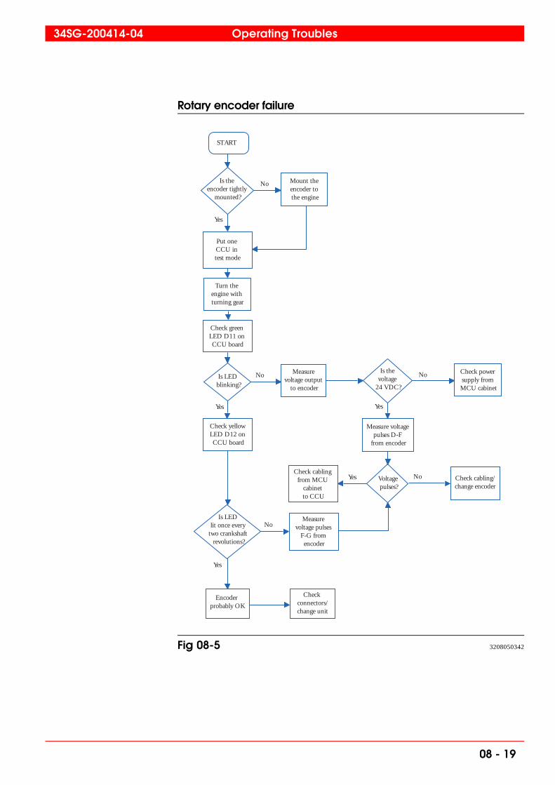
Rotary encoder failure
START
Is the encoder tightly
mounted?
Put one CCU in test mode
Mount the encoder to the engine
Turn the engine with turning gear
Is LED blinking?
Check yellow LED D12 on CCU board
Measure voltage output
to encoder
Is the voltage
24 VDC?
Check cabling from MCU
cabinet to CCU
Check power supply from MCU cabinet
Voltage pulses?
Check cabling/change encoder
Check green LED D11 on CCU board
Is LED lit once every
two crankshaft revolutions?
Encoder probably OK
Measure voltage pulses
F-G from encoder
Measure voltage pulses D-F
from encoder
Check connectors/change unit
Yes
No
No
Yes
No
Yes
NoYes
No
Yes
Fig 08-5 3208050342
34SG-200414-04 Operating Troubles
08 - 19

Inductive pickup sensor failure
START
Stop the engine
Turn the engine with turning gear
Measure voltage between GND and frequency output or
check the left LED on the OTM
The sensor is probably OK
Correct the sensor distance according to instructions
Measure voltage input to OTM
Is the voltage alternating
or is the LED blinking?
Is the voltage for the sensor 24 VDC?
Is the sensor distance
OK?
Change the sensor
Is the voltage
24 VDC?
Check cabling/change OTM
Check fuses in WECS
cabinet
Check cabling/change OTM
Yes
No
No
Yes
No
Yes
No
Yes
Fig 08-6 3208060342
Operating Troubles 34SG-200414-04
08 - 20
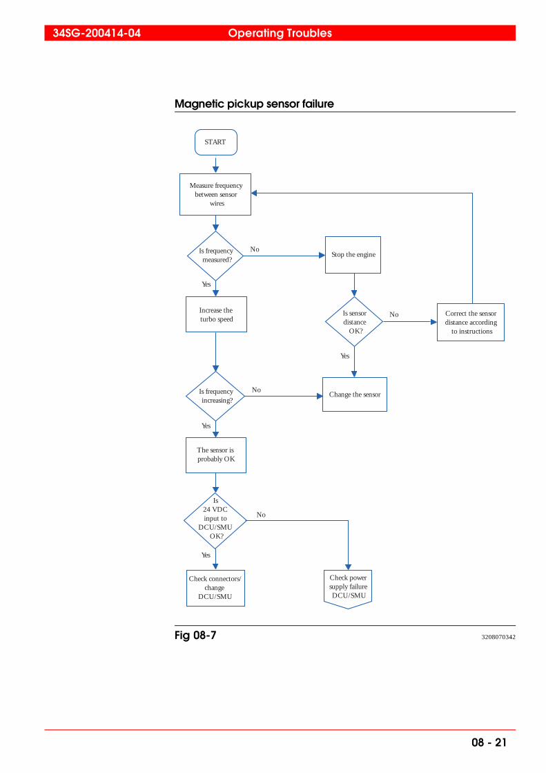
Magnetic pickup sensor failure
START
Measure frequency between sensor
wires
Stop the engine
Increase the turbo speed
Change the sensor
Correct the sensor distance according
to instructions
The sensor is probably OK
Is frequency increasing?
Is sensor distance
OK?
Is frequency measured?
Is 24 VDC input to
DCU/SMU OK?
Check connectors/change
DCU/SMU
Check power supply failure DCU/SMU
No
Yes
No
Yes
No
Yes
No
Yes
Fig 08-7 3208070342
34SG-200414-04 Operating Troubles
08 - 21

Knock sensor failure
START
Is the sensor tightly
mounted?
Is resistance and capacitance
OK?
Tighten the sensor to the engine with 20 Nm, use loctite
on threads
Change the sensor
Measure the sensor resistance; <1Mohm
and a capacitance 800-1600 pF
Is any sensor OK?
Check that KDU has correct
software or change the KDU
Measure the resistance
between sensor wires & engine
body
Is the resistance
infinte?
Check connectors and cabling/change KDU
Change the sensor
No
Yes
No
Yes
No
Yes
No
Yes
Fig 08-8 3208080342
Operating Troubles 34SG-200414-04
08 - 22

Power supply failure CCU
START
Open the cover of the
CCU
Is the LED lit?
Power supply probably OK
Is LED blinking?
12 VDC or 12 VDC and
24 VDC missing
Is there power to any
unit?
24 VDC missing, check fuses in MCU
cabinet
Fuse OK?
Is K1 active?
Check overspeed relay OTM
Check cabling
Check ignition coil for short
circuit
Check green LED D11
on CCU board
Check relay K1 in WECS
cabinet
Check external power supply
Replace the fuse
Measure input voltage to
MCU cabinet
Is voltage 24
VDC?
Check emergency
stop
Is overspeed
relay OTM active?
Yes
No
No
Yes
Yes
No
Yes
No
Yes
No
Yes
No
Yes
No
Fig 08-9 3208090342
34SG-200414-04 Operating Troubles
08 - 23

Power supply failure KDU
START
Open the cover of the KDU
Is the LED lit?
Power supply probably OK
Is voltage 25-26 =
24 VDC?
Is voltage 29-30 =
24 VDC?
24 VDC missing check
fuse in MCU cabinet
Fuse OK?
Is voltage 24 VDC?
Check external power supply
Check cabling
Replace fuse
Check green LED D11 on KDU board
Check voltage output in
MCU cabinet
Change KDU I/O board probably OK
Check flat cable/change
KDU
Is resistance 25-29 and 26-30
<1 ohm?
No
Yes Yes
No
Yes
Yes
No
Yes
No
No No
Yes
Fig 08-10 3208100342
Operating Troubles 34SG-200414-04
08 - 24

CAN-bus failure CCU
START
Open the cover
Disconnect power from the
WECS
CCU software is probably
overloaded or 24V is missing (if also green
LED is blinking)
Check flat cable, CCU. Change the
broken one
Connect CAN terminal resistor.
If they exist, disconnect pins 33-34 and 37-38
Change the CCU
Find the broken cable/unit in the
CAN network
Connect pins 33-34 and
37-38
CAN network probably OK
Is resistance 33-34
and 37-38 ≈ 120 ohm?
Is resistance 33-34 =
60 ohm?
Is resistance 33-37 and
33-38 < 1ohm?
Is yellow LED
blinking?
No
Yes
No
Yes
Yes
No
No
Yes
Fig 08-11 3208110342
34SG-200414-04 Operating Troubles
08 - 25

CAN-bus failure KDU
START
Open the cover
Disconnect power from the WECS
Check flat cable, I/O board. Change
the broken one
Connect CAN terminal resistor.
If they exist, disconnect pins 23-2
and 27-28
Change the KDU
Find the broken cable/unit in the
CAN network
Connect pins 23-24 and
27-28CAN network probably OK
Is resistance
23-24 and 27-28 =120 ohm?
Is resistance 23-24 = 60 ohm?
Is resistance 23-27 and 23-28
< 1ohm
CAN LED D12 only blinking when engine
is running
No
Yes
No
Yes
No
Yes
Fig 08-12 3208120342
Operating Troubles 34SG-200414-04
08 - 26

CAN-bus failure DCU
START
Fix theconfigurationcompile and
reload it
Open thecover and reset
the DCU
Disconnectpower fromthe WECS
DCU software isprobably
overloaded.Change the
configuration
Check flat cable,DCU and SMU
boards. Change thebroken one
Connect CANterminal resistor.
If they exist,disconnect pins
31-31 and 65-66
Change theDCU board
Find the broken cable/unit in
the CANnetwork
Connect pins31-32 and
65-66
CAN networkprobably OK
Isresistance
31-32 and 65-66≈ 120 ohm?
Isresistance 31-65
and 32-66< 1ohm?
DCUCAN LEDblinking?
DVRXconfiguration
OK?
No
Yes
No
Yes
No
No
Yes
Isresistance 31-32
= 60 ohm?
Yes
No
DCU CANLED notblinking
Fig 08-13 3208130342
34SG-200414-04 Operating Troubles
08 - 27

Main/PCC gas valve and ignition test
Switch off the CCU power by disconnecting
power connector X1
Valve opening and
Turn the upper rotating switch
(SW3) to position 1
Turn all rotatingswitches on the
CCU cover boardto 0 position
(testing position)
Switch on the CCU power
supply by reconnecting connector X1
Main gas valve opening and
closing at one second interval
in left-hand cyl- inders controlled
by the CCU
Check the wiring or
replace the valve
No
Main/PCC gas valve
and ignition test part 2
Turn the upper rotating switch
(SW3) to position 2
Yes
closing?
Start
Fig 08-14 3208290404
Operating Troubles 34SG-200414-04
08 - 28

Shutdowns, Emergency (EMG) messages by PLCCode Message Reason Action
CFC0_1S020EST EMG, Control roomemergencypushbutton
Genset control panelemergency pushbutton activated
n/a
CFC0_1K001SDI EMG, Emerg. circuitsafety relay ind.
Safety relay tripped Check the separately informedemergency indications
CFC0_1S023EST EMG, Engine roomemergencypushbutton
Engine room panelemergency pushbutton activated
n/a
BLN0_1F001SDI EMG, Fire fightingalarm
Fire detection systemis activated
Check the cause and follow the localregulations
ZBB0_1A001SDH EMG, Gas alarm level2
Gas alarm 20 % LELreached
Check the cause for the gas leakage
CFC0_1A101SDI EMG, WECS panelemergencypushbutton
WECS panelemergency pushbutton activated
n/a
34SG-200414-04 Operating Troubles
08 - 29

Shutdowns (SHD) messages by PLCCode Message Reason Action
BAE0_1F87NSDI SHD, Differentialcurrent relay tripped
Generator statorshort circuit
protection activated
Check the generator statoraccording to the generator
manufacturer manuals
CFC0_1D008SDI SHD, Engine did notstop in 20 min
After stop commandgiven is maximum 20minutes allowed for
unloading andstopping
Check bus communication
CFC0_1D007SDI SHD, Engine startfailed
Expectedacceleration to
nominal speed notachieved within 50seconds since opencommand given togas regulating unit
Check engine related start failureindications, Check the last gas
regulating unit valve (V018) (and V28if PCC gas line applied)
SOB0_1F162SDI SHD, Engineventilation failed
(Start motor)
Gas ventilationcompleted
information notreceived from WECS
within one minutefrom start command
Check start motor functionality
NHA0_1A001SDI SHD, Exhaust gasventilation shutdown
n/a n/a
ZBB0_1A001SDI SHD, Gas leak testfailed
One of the shut-offvalves or the
ventilation valves areleaking, or the
pressureswitch/transmitter is
broken
Check the shut-off/ventilation valvesfunctionality, Check the pressure
switch/transmitter
ZBB0_1P003SDH SHD, High inlet gaspressure
Too high gas supplypressure to gasregulating unit
Check gas supply line
ZBB0_1P003SDL SHD, Low inlet gaspressure
n/a n/a
ZBB0_1V007SDI SHD, Main gas safetyshut-off valve
Too high pressureafter regulating valve
Check regulating valve functionality
QEP0_1M001SDI SHD, Prelubricationfailed
n/a n/a
SOB0_1F161SDI SHD, Shutdownactive from load red.
The engine has beenoverloaded longerthan defined time
Check load signal to WECS (mA)
CFC0_1S007SDI SHD, Startpreparation failed
Gas leak test ispassed and WECS
ready for startinformation is notreceived within 2
minutes or gasleakage test failed
Check the gas regulating unit valvefunctionalities, Check the WECS startcondition indications (WOIS Control
Display)
CFC0_1A100SDI SHD, WECScommunication
failure shutdown *)
Communicationmalfunction due tocabling problem,
loose connection(s)
Check communication cabling
SCX0_1F201SDI SHD, WECS HWshutdown signal for
the PLC
WECS hardwiredshutdown circuit
contact activated
Check the separately informedshutdown causes
*) DF: Gas trip
Operating Troubles 34SG-200414-04
08 - 30

Alarm (ALM) messages by PLCCode Message Reason Action
CFC0_1F010ALI ALM, AC-powerfailure CFC Panel
CFC panel AC-power supply failure
Check the fuse for the AC supply
SOB0_1F150ALI ALM, Automaticderating active
Some of the deratingcauses are active
Check the separately informedderating cause
CFC0_1F001ALI ALM, AVR alarm Common alarm fromthe AVR or MCB
tripped
Check the AVR display for error,Check all miniature circuit breakers in
the AVR circuit including thegenerator auxiliary terminal box
CFC0_1F012ALI ALM, DC-powerfailure CFC Panel
CFC panel DC-power supply failure
Check the MCBs (miniature circuitbreakers) on the DC supply side
SNB0_1P003AH ALM, Diff. pressureover charge air filter
A
Charge air filterclogged
Clean the air filter
SNB0_1P004AH ALM, Diff. pressureover charge air filter B
Charge air filterclogged
Clean the air filter
VDA0_1B001OVH ALM, Electricalpreheater 1overheated
Electrical preheaterthermo relay tripped
Check the thermo relay
VDA0_1B002OVH ALM, Electricalpreheater 2overheated
Electrical preheaterthermo relay tripped
Check the thermo relay
VDA0_1A001MFI ALM, Electricalpreheating control
center fault
Electrical preheaterovercurrent/shortcircu
it tripped
Check the overcurrent/shortcircuitrelay
VDA0_1A001AFI ALM, Electricalpreheating Start/Stop
fault
Electrical preheateractivation is not
according to givencommand
Check the functionality of the maincontactor, Check the wiring for
running information and start/stopcommands
CFC0_1S002ALI ALM, Engine controlmode conflict betw.
WECS/PLC
Control modeconflict, hardwiredWECS parallell with
grid informationfaulty
Check the hardwired parallel withgrid information to WECS
NHA0_1A001ALI ALM, Exh.vent.Emergency venting
active (20 min.)
Emergency (natural)venting is activateddue to ventilation
failure
Check the separately informedreasons (motor control center fault,
start/stop fault, valve fault, flowswitch fault)
NHA0_1M001MFI
ALM, Exh.vent.fanmotor control center
fault
Exhaust ventilationfan motor
overcurrent/shortcircuit tripped
Check the overcurrent/shortcircuitrelay
NHA0_1M001AFI ALM, Exh.vent.fanStart/Stop command
failure
Exhaust ventilationfan motor activationis not according togiven command
Check the functionality of the maincontactor, Check the wiring for
running information and start/stopcommands
NHA0_1Q001ALI ALM, Exh.vent.flowswitch fault
Exhaust ventilationflow switch fault, dueto flow indication notreceived within pre-defined time since
activation of exhaustventilation or due to
indication of floweven though exhaust
gas ventilation notactive
Check the exhaust ventilation fanoperation and the flow switch
functionality
34SG-200414-04 Operating Troubles
08 - 31

Alarm (ALM) messages by PLCCode Message Reason Action
NHA0_1A001VFI ALM, Exh.vent.valvefault
Exhaust ventilationvalve is not openedwithin pre-defined
time from thecommand
Check the ventilation valvefunctionality, Check the valve open
indication switch, Check the airsupply
NHA0_1V001OPN ALM, Explosion reliefvalve 1 open
Explosion relief valveopened
Check the explosion relief valve
NHA0_1V002OPN ALM, Explosion reliefvalve 2 open
Explosion relief valveopened
Check the explosion relief valve
NHA0_1V003OPN ALM, Explosion reliefvalve 3 open
Explosion relief valveopened
Check the explosion relief valve
ZBB0_1A001ALI ALM, Gas alarm level1 Gas alarm 10 % LELreached
Check the cause for the gasleakage
ZBB0_1V015ALI ALM, Gas shutoffvalve V015 leaking
Pressure raisedetected betweengas shutoff valves
V015 and V018during gas leakage
test
Check the V015 gas shutoff valve forleakages
ZBB0_1V015TFI ALM, Gas shutoffvalve V015 stuck
Sufficient pressurenot detected at gasshutoff valve V018
during gas leakagetest
Check the V015 gas shutoff valvefunctionality
ZBB0_1V018ALI ALM, Gas shutoffvalve V018 leaking
Pressure lostbetween gas shutoff
valves V015 andV018 during gas
leakage test
Check the V018 gas shutoff valve forleakages
BAG0_1B001MFI ALM, Gen anticond.heater, control
center fault
Gen.anticondensation
heaterovercurrent/shortcircu
it tripped
Check the overcurrent/shortcircuitrelay
BAG0_1B001AFI ALM, Gen anticond.heater, Start/Stop
fault
Gen.anticondensation
heater activation isnot according togiven command
Check the functionality of the maincontactor, Check the wiring for
running information and start/stopcommands
BAE0_1Q000MCB ALM, Gen. breakercommon alarm (MCB
open)
Generator MV panelcommon alarm,
MCB tripped
Check the wiring
BAE0_1Q000ALI ALM, Gen. breakerposition error
Breaker open andclose signals active
OR none of thesignals active
Check the position contacts andwiring
BAE0_1E001ALI ALM, Gen. breakerSF6 pressure low
Leakage on breaker,SF6 is leaking out
Check the SF6 pressure from localgauge. If low, contact breakermanufacturer, otherwise check
wiring and contacts.
CFC0_1S012TRI ALM, Gen. breakertip circuit indication
Breaker trip circuitactivated
Check the separately informedbreaker trip cause
CFC0_1S012TRP ALM, Gen. breakertrip (Primary)
Breaker trip circuitactivated
Check the separately informedbreaker trip cause
Operating Troubles 34SG-200414-04
08 - 32

Alarm (ALM) messages by PLCCode Message Reason Action
BAE0_1Q001ALI ALM, Gen. breakertruck position error
Breaker service andisolated signals
active OR none ofthe signals active
Check the position contacts andwiring
BAE0_1Q009ALI ALM, Gen. earthingdisconnector position
error
Breaker open andclose signals active
OR none of thesignals active
Check the position contacts andwiring
BAE0_1F000MCB ALM, Gen. measuringMCB open
Generator junctionbox MCB tripped
Check the wiring
BAE0_1F51N1AOPR ALM, Gen. Prot.,Earth fault I01 trip
Earth fault protectionactivated
Check the prot. relay event recorder.Check the earth fault reasons
BAE0_1F51N1BOPR ALM, Gen. Prot.,Earth fault I01> trip
Earth fault protectionactivated
Check the prot. relay event recorder.Check the earth fault reasons
BAE0_1F51N2AOPR ALM, Gen. Prot.,Earth fault I02 trip
Earth fault protectionactivated
Check the prot. relay event recorder.Check the earth fault reasons
BAE0_1F51N2BOPR ALM, Gen. Prot.,Earth fault I02> trip
Earth fault protectionactivated
Check the prot. relay event recorder.Check the earth fault reasons
BAE0_1F59NAOPR ALM, Gen. Prot.,Earth fault U0 trip
Earth fault protectionactivated
Check the prot. relay event recorder.Check the earth fault reasons
BAE0_1F59NBOPR ALM, Gen. Prot.,Earth fault U0> trip
Earth fault protectionactivated
Check the prot. relay event recorder.Check the earth fault reasons
BAE0_1F67NOPR ALM, Gen. Prot.,Earth fault,
directional I0 trip
Earth fault protectionactivated
Check the prot. relay event recorder.Check the earth fault reasons
BAE0_1F51AOPR ALM, Gen. Prot.,Overcurrent I trip
Activation of primarygenerator short-
circuit protection if afault occurs in the
busbar or in theutility. Possible other
reasons foractivation:
overloadingprotection of the
generator and as aback-up for the
differential relay incase of stator short
circuits.
Check the prot. relay event recorder.Check for reasons for short-circuits
BAE0_1F81HOPR ALM, Gen. Prot.,Overfrequency f
Sudden loss of load Check the prot. relay event recorder.Check load fluctuations and reasons
for loss of load
BAE0_1F59AOPR ALM, Gen. Prot.,Overvoltage U trip
Activation due toprolonged operationwith excessive over
voltage or in case ofAVR failures or
network disturbances
Check the prot. relay event recorder.Check for reasons for overvoltages,
Check the AVR
BAE0_1F59BOPR ALM, Gen. Prot.,Overvoltage U> trip
Activation due toprolonged operationwith excessive over
voltage or in case ofAVR failures or
network disturbances
Check the prot. relay event recorder.Check for reasons for overvoltages,
Check the AVR
34SG-200414-04 Operating Troubles
08 - 33

Alarm (ALM) messages by PLCCode Message Reason Action
BAE0_1F32AOPR ALM, Gen. Prot.,Reverse power P- trip
Activation ofprotection for the
prime mover in orderto ensure that thegenerator will notact as a motor.
Detection of theamount of reverse
power flow in (watts)that would occur ifthe engine lose its
input power.
Check the prot. relay event recorder.Check for reverse power flow reasons
BAE0_1F50AOPR ALM, Gen. Prot.,Shortcircuit I> trip
Activation of primarygenerator short-
circuit protection if afault occurs in the
busbar or in theutility. Possible other
reasons foractivation:
overloadingprotection of the
generator and as aback-up for the
differential relay incase of stator short
circuits.
Check the prot. relay event recorder.Check for reasons for short-circuits
BAE0_1F49AOPR ALM, Gen. Prot.,Thermal overload
Long-term sensitiveoverloading
protection of thegenerator activated
Check the prot. relay event recorder.Check load fluctuations and reasons
for overloading
BAE0_1F46AOPR ALM, Gen. Prot.,Unbalance load I2 >
Unbalanced loads,unbalanced system
faults, openconductors, or other
unsymmetricaloperating condition
Check the prot. relay event recorder.Check for possible reasons for
unsymmetrical operation
BAE0_1F81LOPR ALM, Gen. Prot.,Underfrequency f <
Sudden loss of inputpower to the systemor due to a sudden
increase of load
Check the prot. relay event recorder.Check load fluctuations and reasons
for loss of load
BAE0_1F40AOPR ALM, Gen. Prot.,Underreactance X trip
Detection ofexcitation faults
Check the prot. relay event recorder.Check the excitation system
BAE0_1F27AOPR ALM, Gen. Prot.,Undervoltage U <
Voltage belowallowed limit, An
under voltagecondition in a power
system may be aresult of, a fault in
the voltageregulator, short
circuits, starting of asynchronous or
induction motor,transformer
energising etc
Check the prot. relay event recorder.Check the voltage regulator, Check
causes for short circuits
Operating Troubles 34SG-200414-04
08 - 34

Alarm (ALM) messages by PLCCode Message Reason Action
BAE0_1F51VOPR ALM, Gen. Prot.,Voltage restr.
Overcurrent I 7> (U)
Activation of back-up protection todisconnect the
generator if a systemfault has not beencleared by other
protective devicesafter a sufficient time
delay has elapsed
Check the prot. relay event recorder.Check also for overcurrent indications
BAE0_1F000ALI ALM, Gen. protectionrelay fault
Generatorprotection relay
internal fault
Check the protection relay display oruse the protection relay program
(VAMPSet) to identify the problem
BAN0_1Q000ALI ALM, Grounddisconnector (NP)
position error
Breaker open andclose signals active
OR none of thesignals active
Check the position contacts andwiring
ZBB0_1P002AH ALM, High diff.pressure over gas filter
Gas regulating unitgas filter clogged
Replace or clean the gas filter
ZBB0_1P003AH ALM, High inlet gaspressure
Too high gas supplypressure to gasregulating unit
Check gas supply line
ZBB0_1T001AH ALM, High inlet gastemperature
Too high gas supplytemperature to gas
regulating unit
Check gas supply line
SVH0_1M001MFI ALM, HT coolingwater pump control
center fault
HT cooling waterpump motor
overcurrent/shortcircuit tripped
Check the overcurrent/shortcircuitrelay
SVH0_1M001AFI ALM, HT coolingwater pump
Start/Stop fault
HT cooling waterpump motor
activation is notaccording to given
command
Check the functionality of the maincontactor, Check the wiring for
running information and start/stopcommands
ZBB0_1P003AL ALM, Low inlet gaspressure
Low high gas supplypressure to gasregulating unit
Check gas supply line
ZBB0_1T001AL ALM, Low inlet gastemperature
Low high gas supplytemperature to gas
regulating unit
Check gas supply line
VEA0_1L001AL ALM, Low level in HTexpansion tank
Low water level in HTexpansion tank
Check the level in the HT expansionlevel
VEA012L001AL ALM, Low level in LTexpansion tank
Low water level in LTexpansion tank
Check the level in the LT expansionlevel
SVL0_1M001MFI ALM, LT coolingwater pump control
center fault
LT cooling waterpump motor
overcurrent/shortcircuit tripped
Check the overcurrent/shortcircuitrelay
SVL0_1M001AFI ALM, LT coolingwater pump
Start/Stop fault
LT cooling waterpump motor
activation is notaccording to given
command
Check the functionality of the maincontactor, Check the wiring for
running information and start/stopcommands
34SG-200414-04 Operating Troubles
08 - 35
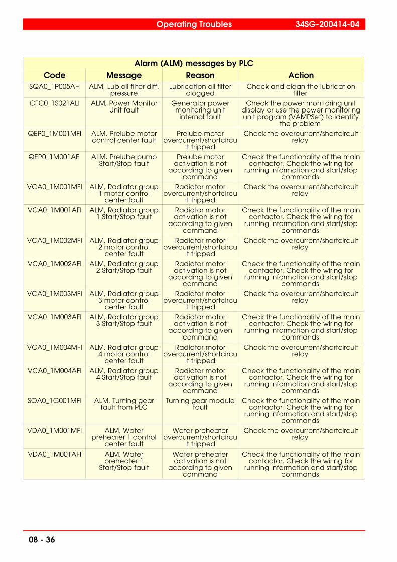
Alarm (ALM) messages by PLCCode Message Reason Action
SQA0_1P005AH ALM, Lub.oil filter diff.pressure
Lubrication oil filterclogged
Check and clean the lubricationfilter
CFC0_1S021ALI ALM, Power MonitorUnit fault
Generator powermonitoring unit
internal fault
Check the power monitoring unitdisplay or use the power monitoringunit program (VAMPSet) to identify
the problem
QEP0_1M001MFI ALM, Prelube motorcontrol center fault
Prelube motorovercurrent/shortcircu
it tripped
Check the overcurrent/shortcircuitrelay
QEP0_1M001AFI ALM, Prelube pumpStart/Stop fault
Prelube motoractivation is not
according to givencommand
Check the functionality of the maincontactor, Check the wiring for
running information and start/stopcommands
VCA0_1M001MFI ALM, Radiator group1 motor control
center fault
Radiator motorovercurrent/shortcircu
it tripped
Check the overcurrent/shortcircuitrelay
VCA0_1M001AFI ALM, Radiator group1 Start/Stop fault
Radiator motoractivation is not
according to givencommand
Check the functionality of the maincontactor, Check the wiring for
running information and start/stopcommands
VCA0_1M002MFI ALM, Radiator group2 motor control
center fault
Radiator motorovercurrent/shortcircu
it tripped
Check the overcurrent/shortcircuitrelay
VCA0_1M002AFI ALM, Radiator group2 Start/Stop fault
Radiator motoractivation is not
according to givencommand
Check the functionality of the maincontactor, Check the wiring for
running information and start/stopcommands
VCA0_1M003MFI ALM, Radiator group3 motor control
center fault
Radiator motorovercurrent/shortcircu
it tripped
Check the overcurrent/shortcircuitrelay
VCA0_1M003AFI ALM, Radiator group3 Start/Stop fault
Radiator motoractivation is not
according to givencommand
Check the functionality of the maincontactor, Check the wiring for
running information and start/stopcommands
VCA0_1M004MFI ALM, Radiator group4 motor control
center fault
Radiator motorovercurrent/shortcircu
it tripped
Check the overcurrent/shortcircuitrelay
VCA0_1M004AFI ALM, Radiator group4 Start/Stop fault
Radiator motoractivation is not
according to givencommand
Check the functionality of the maincontactor, Check the wiring for
running information and start/stopcommands
SOA0_1G001MFI ALM, Turning gearfault from PLC
Turning gear modulefault
Check the functionality of the maincontactor, Check the wiring for
running information and start/stopcommands
VDA0_1M001MFI ALM, Waterpreheater 1 control
center fault
Water preheaterovercurrent/shortcircu
it tripped
Check the overcurrent/shortcircuitrelay
VDA0_1M001AFI ALM, Waterpreheater 1
Start/Stop fault
Water preheateractivation is not
according to givencommand
Check the functionality of the maincontactor, Check the wiring for
running information and start/stopcommands
Operating Troubles 34SG-200414-04
08 - 36
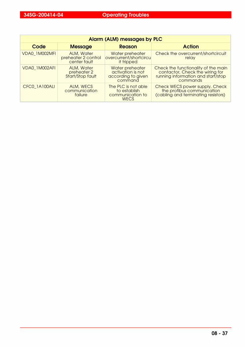
Alarm (ALM) messages by PLCCode Message Reason Action
VDA0_1M002MFI ALM, Waterpreheater 2 control
center fault
Water preheaterovercurrent/shortcircu
it tripped
Check the overcurrent/shortcircuitrelay
VDA0_1M002AFI ALM, Waterpreheater 2
Start/Stop fault
Water preheateractivation is not
according to givencommand
Check the functionality of the maincontactor, Check the wiring for
running information and start/stopcommands
CFC0_1A100ALI ALM, WECScommunication
failure
The PLC is not ableto establish
communication toWECS
Check WECS power supply, Checkthe profibus communication
(cabling and terminating resistors)
34SG-200414-04 Operating Troubles
08 - 37

Derating (DER) messages by PLCCode Message Reason Action
SOB0_1F157INF DER, Derating active Some of the deratingcauses are active
Check the separately informedderating cause
SOB0_1F152INF DER, Pex, Exhaust gasback pressure
Derating highExhaust Gas back
pressure due toclogged heat
recovery boiler orback end cleaning
devices
Check the heat recovery boiler orback end cleaning devices
SOB0_1F159INF DER, Pgas, Gas feedpressure
Derating, due to lowgas feed pressure
Check the gas supply line pressure
SOB0_1F156INF DER, Tamb, Air inlettemperature
Derating, high airinlet temperature
due to high ambienttemperature
n/a
SOB0_1F154INF DER, Tcw, Charge aircoolant temperature
Derating, highcharge air coolant(LT) temp due to;
High ambienttemperature,
external coolingsystem problems
Check cooling system
SOB0_1F155INF DER, Tht, HT watertemperature
Derating, low HTwater temperature
Check the pre-heating of the engine
SOB0_1F153INF DER, Trec, Charge airtemp in receiver
Derating, highcharge air temp in
receiver due to; Highambient
temperature, High LTwater temperature,CA cooler blow-by,Contaminated CA
coolers
Check cooling system, Checkdifference between LT and CA
temperature, Check CA diff pressure
Operating Troubles 34SG-200414-04
08 - 38

Sensor Failure (SF) messages by PLCCode Message Reason Action
SNB0_1P003SF SF, Diff. pressure overcharge air filter A
Sensor broken orwiring fault (broken
or loose connections)
Check the sensor mA level at the PLCinput card, if the mA level (4-20mA) isok to the card, replace the PLC inputcard. If the mA level is not within the
levels check the cabling to the sensorand the sensor itself
SNB0_1P004SF SF, Diff. pressure overcharge air filter B
Sensor broken orwiring fault (broken
or loose connections)
Check the sensor mA level at the PLCinput card, if the mA level (4-20mA) isok to the card, replace the PLC inputcard. If the mA level is not within the
levels check the cabling to the sensorand the sensor itself
ZBB0_1P002SF SF, Diff. pressure overgasfilter
Sensor broken orwiring fault (broken
or loose connections)
Check the sensor mA level at the PLCinput card, if the mA level (4-20mA) isok to the card, replace the PLC inputcard. If the mA level is not within the
levels check the cabling to the sensorand the sensor itself
ZBB0_1Q001SF SF, Gas flow Sensor broken orwiring fault (broken
or loose connections)
Check the sensor mA level at the PLCinput card, if the mA level (4-20mA) isok to the card, replace the PLC inputcard. If the mA level is not within the
levels check the cabling to the sensorand the sensor itself
VCA0_1T002SF SF, HT watertemperature after
radiator
Sensor broken orwiring fault (broken
or loose connections)
Check the resistance level at thepanel terminals and compare to theactual temperature. If the resistance
is within the actual temperature/resistance levels replace the PT100
card. If the resistance is not within thelevels, check the cabling and
connections. If the cabling andconnections are ok, replace the
sensor.
ZBB0_1P003SF SF, Inlet gas pressure Sensor broken orwiring fault (broken
or loose connections)
Check the sensor mA level at the PLCinput card, if the mA level (4-20mA) isok to the card, replace the PLC inputcard. If the mA level is not within the
levels check the cabling to the sensorand the sensor itself
ZBB0_1T001SF SF, Inlet gastemperature
Sensor broken orwiring fault (broken
or loose connections)
Check the resistance level at thepanel terminals and compare to theactual temperature. If the resistance
is within the actual temperature/resistance levels replace the PT100
card. If the resistance is not within thelevels, check the cabling and
connections. If the cabling andconnections are ok, replace the
sensor.
VCA0_1T001SF SF, LT watertemperature after
radiator
Sensor broken orwiring fault (broken
or loose connections)
Check the resistance level at thepanel terminals and compare to theactual temperature. If the resistance
is within the actual temperature/resistance levels replace the PT100
card. If the resistance is not within thelevels, check the cabling and
connections. If the cabling andconnections are ok, replace the
sensor.
34SG-200414-04 Operating Troubles
08 - 39
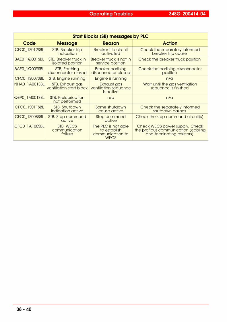
Start Blocks (SB) messages by PLCCode Message Reason Action
CFC0_1S012SBL STB, Breaker tripindication
Breaker trip circuitactivated
Check the separately informedbreaker trip cause
BAE0_1Q001SBL STB, Breaker truck inisolated position
Breaker truck is not inservice position
Check the breaker truck position
BAE0_1Q009SBL STB, Earthingdisconnector closed
Breaker earthingdisconnector closed
Check the earthing disconnectorposition
CFC0_1S007SBL STB, Engine running Engine is running n/a
NHA0_1A001SBL STB, Exhaust gasventilation start block
Exhaust gasventilation sequence
is active
Wait until the gas ventilationsequence is finished
QEP0_1M001SBL STB, Prelubricationnot performed
n/a n/a
CFC0_1S011SBL STB, Shutdownindication active
Some shutdowncause active
Check the separately informedshutdown causes
CFC0_1S008SBL STB, Stop commandactive
Stop commandactive
Check the stop command circuit(s)
CFC0_1A100SBL STB, WECScommunication
failure
The PLC is not ableto establish
communication toWECS
Check WECS power supply, Checkthe profibus communication (cabling
and terminating resistors)
Operating Troubles 34SG-200414-04
08 - 40

Status/Events messages by PLCCode Message Reason Action
CFC0_1S005ACK AVR excitation on Status n/a
CFC0_1S010INF Breaker control, opencommand
Status n/a
CFC0_1S010OPC Breaker open command Status n/a
CFC0_1S012RST Breaker trip reset Status n/a
CFC0_1S030DIS Disable loadsharing Status n/a
CFC0_1S030ENB Enable loadsharing Status n/a
CFC0_1S002SEL Engine control, speed(droop)
Status n/a
CFC0_1S007INF Engine control, startcommand
Status n/a
CFC0_1S008INF Engine control, stopcommand
Status n/a
CFC0_1S002DRO Engine droop control Status n/a
CFC0_1S002KWO Engine kW control Status n/a
CFC0_1S007STO Engine start command Status n/a
CFC0_1S008SPO Engine stop command Status n/a
NHA0_1A001RNI Exhaust gas vent. fan running Status, Exhaust gasventilation fan running
n/a
NHA0_1Q001INF Flow switch position Status, Exhaust gasventilation fan flow
indicator
n/a
PCC0_1M001RNI Fuel feeder running Status n/a
ZBB0_1P006INF Gas leak test pressure status,P06
Status, Gas leak testpressure sensor pressurized
n/a
ZBB0_1V015INF Gas shutoff valve status,V015
Status, Gas shutoff valveopen
n/a
ZBB0_1V018INF Gas shutoff valve status,V018
Status, Gas shutoff valveopen
n/a
ZBB0_1V014INF Gas ventilation valve status,V014
Status, Gas ventilationvalve open
n/a
ZBB0_1V016INF Gas ventilation valve status,V016
Status, Gas ventilationvalve open
n/a
ZBB0_1V019INF Gas ventilation valve status,V019
Status, Gas ventilationvalve open
n/a
BAE0_1Q000CLO Gen. breaker closed Status n/a
BAE0_1Q000OPN Gen. breaker open Status n/a
BAE0_1Q001OKP Gen. breaker truck inisolated position
Status n/a
34SG-200414-04 Operating Troubles
08 - 41

Status/Events messages by PLCCode Message Reason Action
BAE0_1Q001NOP Gen. breaker truck in serviceposition
Status n/a
BAE0_1Q009CLO Gen. earthing disconnectorclosed
Status n/a
BAE0_1Q009OPN Gen. earthing disconnectoropen
Status n/a
CFC0_1S014ACK Gen. voltage supervision Status n/a
CFC0_1S001SEL Generating set control, automode from M1 panel
Status n/a
CFC0_1S001INF Generating set control,manual mode from WOIS
n/a n/a
CFC0_1S003SEL Generator control, voltage(droop)
Status n/a
CFC0_1S003DRO Generator droop control Status n/a
CFC0_1S003PFO Generator P.F. Control Status n/a
BAN0_1Q000CLO Ground disconnector (NP)closed
Status n/a
BAN0_1Q000OPN Ground disconnector (NP)open
Status n/a
SVH0_1M001RNI HT-water cooling pump running Status n/a
SOB0_1E204INF Idle running Status, Sequence n/a
CFC0_1S030INF Load sharing selected Status n/a
SOB0_1E207INF Loading Status, Sequence n/a
SVL0_1M001RNI LT-water cooling pump running Status n/a
SOB0_1E208INF Normal operation Status, Sequence n/a
CFC0_1S034ACK Parallel with grid Status n/a
VDA0_1A001RNI Preheating on Status n/a
VDA0_1M001RNI Preheating pump 1 running Status n/a
VDA0_1M002RNI Preheating pump 2 running Status n/a
QEP0_1M001RNI Prelubrication pump running Status n/a
VCA0_1M001RNI Radiator group 1 running Status n/a
VCA0_1M002RNI Radiator group 2 running Status n/a
VCA0_1M003RNI Radiator group 3 running Status n/a
Operating Troubles 34SG-200414-04
08 - 42
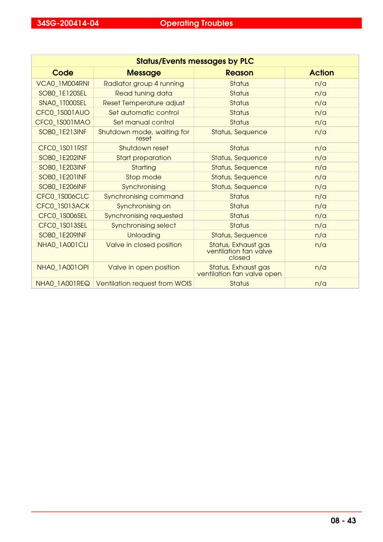
Status/Events messages by PLCCode Message Reason Action
VCA0_1M004RNI Radiator group 4 running Status n/a
SOB0_1E120SEL Read tuning data Status n/a
SNA0_1T000SEL Reset Temperature adjust Status n/a
CFC0_1S001AUO Set automatic control Status n/a
CFC0_1S001MAO Set manual control Status n/a
SOB0_1E213INF Shutdown mode, waiting forreset
Status, Sequence n/a
CFC0_1S011RST Shutdown reset Status n/a
SOB0_1E202INF Start preparation Status, Sequence n/a
SOB0_1E203INF Starting Status, Sequence n/a
SOB0_1E201INF Stop mode Status, Sequence n/a
SOB0_1E206INF Synchronising Status, Sequence n/a
CFC0_1S006CLC Synchronising command Status n/a
CFC0_1S013ACK Synchronising on Status n/a
CFC0_1S006SEL Synchronising requested Status n/a
CFC0_1S013SEL Synchronising select Status n/a
SOB0_1E209INF Unloading Status, Sequence n/a
NHA0_1A001CLI Valve in closed position Status, Exhaust gasventilation fan valve
closed
n/a
NHA0_1A001OPI Valve in open position Status, Exhaust gasventilation fan valve open
n/a
NHA0_1A001REQ Ventilation request from WOIS Status n/a
34SG-200414-04 Operating Troubles
08 - 43

08.2.1 Cylinder combustion failure check lists
LR, High exhaust gas temperature
Cause CheckLeaking main gas valve A leaking Main gas valve can cause this. Swap the
malfunctioning gas valve to another cylinder in order to seeif the fault is moving.
Incorrect (too rich) Air/Fuel ratio If the air/fuel ratio is too rich, normally all cylinders haveincreased exhaust gas temperatures. The problem can bedue to incorrect wastegate adjustment or that thewastegate is fully closed. Check wastegate calibrationand functionality. If the wastegate is fully closed, air flow toand from the engine might be restrictedToo high pressure drop over:- Intake air filters - Charge Air-coolers - Turbo charger nozzle rings Exhaust system after engine.For instance exhaust boilers, catalytic converters a.s.o.
Exhaust gas valves Exhaust gas valve. To check condition of valves perform a"Cylinder tightness test" of the cylinder (see chapter 12 A ) Reasons for leakage might be: - Valve jamming when open- "Negative" valve clearance- Valve/seat sealing surface blow by (burned)
Operating Troubles 34SG-200414-04
08 - 44

SHD, High exhaust gas temperature
Cause CheckBig load step If a too big load step is attempted the exhaust
gas temperatures will increase rapidly.
Leaking main gas valve A leaking Main gas valve can cause this. Swapthe malfunctioning gas valve to another cylinder
in order to see if the fault is moving.
Incorrect (too rich) Air/Fuel ratio If the air/fuel ratio is too rich, normally allcylinders have increased exhaust gastemperatures. The problem can be due toincorrect wastegate adjustment or that thewastegate is fully closed. Check wastegatecalibration and functionality. If the wastegate isfully closed, air flow to and from the enginemight be restrictedToo high pressure drop over:- Intake air filters- Charge Air-coolers- Turbo charger nozzle ringsExhaust system after engine. For instanceexhaust boilers, catalytic converters a.s.o.
Exhaust gas valves Exhaust gas valve. To check condition of valvesperform a "Cylinder tightness test" of the cylinder(see chapter 12 A)Reasons for leakage might be:- Valve jamming when open- "Negative" valve clearance- Valve/seat sealing surface blow by (burned)
34SG-200414-04 Operating Troubles
08 - 45

ALM, High exhaust gas temperature, cyl. n
Cause CheckBig load step If a too big load step is attempted the exhaust
gas temperatures will increase rapidly.
Leaking main gas valve A leaking Main gas valve can cause this. Swapthe malfunctioning gas valve to another cylinder
in order to see if the fault is moving.
Incorrect (too rich) Air/Fuel ratio If the air/fuel ratio is too rich, normally allcylinders have increased exhaust gastemperatures. The problem can be due toincorrect wastegate adjustment or that thewastegate is fully closed. Check wastegatecalibration and functionality. If the wastegate isfully closed, air flow to and from the enginemight be restrictedToo high pressure drop over:- Intake air filters- Charge Air-coolers- Turbo charger nozzle ringsExhaust system after engine. For instanceexhaust boilers, catalytic converters a.s.o.
Exhaust gas valves Exhaust gas valve. To check condition of valvesperform a "Cylinder tightness test" of the cylinder(see chapter 12 A)Reasons for leakage might be:- Valve jamming when open- "Negative" valve clearance- Valve/seat sealing surface blow by (burned)
Operating Troubles 34SG-200414-04
08 - 46

SHD, High dev. exh. gas temp. cyl./averageCylinder exhaust gas temperature is significantly higher than engineaverage
Cause CheckBig load step If a too big load step is attempted the exhaust
gas temperatures will increase rapidly.
Leaking main gas valve A leaking Main gas valve can cause this. Swapthe malfunctioning gas valve to another cylinder
in order to see if the fault is moving.
Incorrect (too rich) Air/Fuel ratio If the air/fuel ratio is too rich, normally allcylinders have increased exhaust gastemperatures. The problem can be due toincorrect wastegate adjustment or that thewastegate is fully closed. Check wastegatecalibration and functionality. If the wastegate isfully closed, air flow to and from the enginemight be restrictedToo high pressure drop over:- Intake air filters- Charge Air-coolers- Turbo charger nozzle ringsExhaust system after engine. For instanceexhaust boilers, catalytic converters a.s.o.
Exhaust gas valves Exhaust gas valve. To check condition of valvesperform a "Cylinder tightness test" of the cylinder(see chapter 12 A)Reasons for leakage might be:- Valve jamming when open- "Negative" valve clearance- Valve/seat sealing surface blow by (burned)
34SG-200414-04 Operating Troubles
08 - 47

ALM, High dev. exh. gas temp. cyl./averageCylinder exhaust gas temperature is significantly higher than engineaverage
Cause CheckBig load step If a too big load step is attempted the exhaust
gas temperatures will increase rapidly.
Leaking main gas valve A leaking Main gas valve can cause this. Swapthe malfunctioning gas valve to another cylinder
in order to see if the fault is moving.
Incorrect (too rich) Air/Fuel ratio If the air/fuel ratio is too rich, normally allcylinders have increased exhaust gastemperatures. The problem can be due toincorrect wastegate adjustment or that thewastegate is fully closed. Check wastegatecalibration and functionality. If the wastegate isfully closed, air flow to and from the enginemight be restrictedToo high pressure drop over:- Intake air filters- Charge Air-coolers- Turbo charger nozzle ringsExhaust system after engine. For instanceexhaust boilers, catalytic converters a.s.o.
Exhaust gas valves Exhaust gas valve. To check condition of valvesperform a "Cylinder tightness test" of the cylinder(see chapter 12 A)Reasons for leakage might be:- Valve jamming when open- "Negative" valve clearance- Valve/seat sealing surface blow by (burned)
Operating Troubles 34SG-200414-04
08 - 48
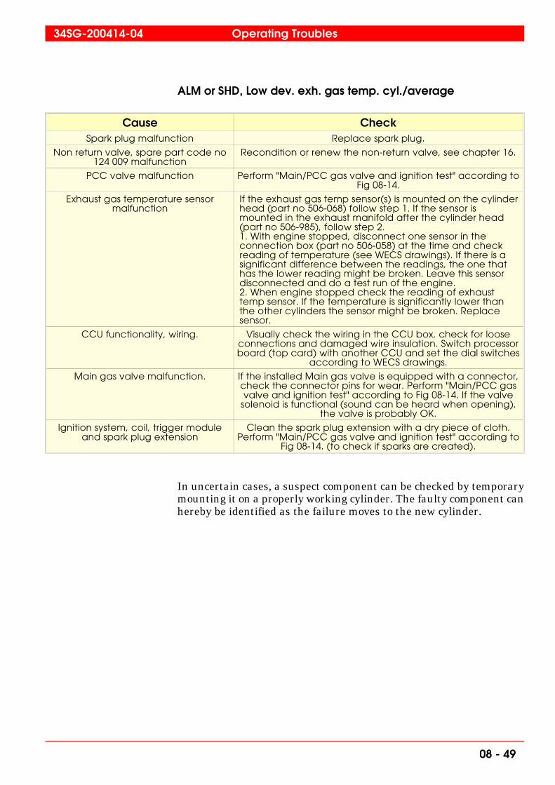
ALM or SHD, Low dev. exh. gas temp. cyl./average
Cause CheckSpark plug malfunction Replace spark plug.
Non return valve, spare part code no124 009 malfunction
Recondition or renew the non-return valve, see chapter 16.
PCC valve malfunction Perform "Main/PCC gas valve and ignition test" according toFig 08-14.
Exhaust gas temperature sensormalfunction
If the exhaust gas temp sensor(s) is mounted on the cylinderhead (part no 506-068) follow step 1. If the sensor ismounted in the exhaust manifold after the cylinder head(part no 506-985), follow step 2.1. With engine stopped, disconnect one sensor in theconnection box (part no 506-058) at the time and checkreading of temperature (see WECS drawings). If there is asignificant difference between the readings, the one thathas the lower reading might be broken. Leave this sensordisconnected and do a test run of the engine.2. When engine stopped check the reading of exhausttemp sensor. If the temperature is significantly lower thanthe other cylinders the sensor might be broken. Replacesensor.
CCU functionality, wiring. Visually check the wiring in the CCU box, check for looseconnections and damaged wire insulation. Switch processorboard (top card) with another CCU and set the dial switches
according to WECS drawings.
Main gas valve malfunction. If the installed Main gas valve is equipped with a connector,check the connector pins for wear. Perform "Main/PCC gasvalve and ignition test" according to Fig 08-14. If the valve
solenoid is functional (sound can be heard when opening),the valve is probably OK.
Ignition system, coil, trigger moduleand spark plug extension
Clean the spark plug extension with a dry piece of cloth.Perform "Main/PCC gas valve and ignition test" according to
Fig 08-14. (to check if sparks are created).
In uncertain cases, a suspect component can be checked by temporarymounting it on a properly working cylinder. The faulty component canhereby be identified as the failure moves to the new cylinder.
34SG-200414-04 Operating Troubles
08 - 49

ALM, Max. temp. compensation, cyl. n
Cause CheckCylinder gas duration has reached
maximum offset value. The cylinder need much more or much less main gas valve
duration than average to maintain exhaustgas temperature.
This alarm has many possible causes. To be able to findthe reason the exhaust gas temperature trends has tobe monitored. If the exhaust gas temperature tends tofall below average please refer to ALM, Low dev. exh.
gas temp. cyl./averageIf the trend is showing a rising exhaust gas temperature
please refer to ALM, High dev. exh. gas temp.cyl./average
ALM, Cyl. disabled due to temp. dev., cyl. n (Optional)
Cause CheckThe cylinder combustion has failed and the
fuel injection to the cylinder is disabled.This alarm has many possible causes. To be able to findthe reason the exhaust gas temperature trends has tobe monitored. If the exhaust gas temperature tends tofall below average please refer to ALM, Low dev. exh.
gas temp. cyl./averageIf the trend is showing a rising exhaust gas temperature
please refer to ALM, High dev. exh. gas temp.cyl./average
08.3 Trouble shooting for air starter
Pos. Trouble1. Starting motor does not run
a) No air supply. Check for blockage or damage to air supply lines ortank.
b) Damaged turbine assembly. Inspect turbine assembly and power train and repair orreplace if necessary.
c) Foreign material in starting motorand/or piping.
Remove motor assembly and/or piping and removeblockage.
d) Blocked exhaust system. Remove housing exhaust cover and check forblockage.
e) Defective control valve or relay valve.
Replace control valve or relay valve.
2. Loss of powera) Low air pressure to starter. Check air supply.b) Restricted air supply line. Check for blockage or damage to air lines.c) Relay valve malfunctioning. Clean or replace lines or relay valve. Lube relay valve.d) Exhaust flow restricted. Check for blocked or damaged piping. Clean or
replace piping. Check for dirt or foreign material andclean or remove. Check for ice build-up. Melt ice andreduce moisture build-up to starter.
e) Damaged turbine assembly. Replace turbine assembly.
Operating Troubles 34SG-200414-04
08 - 50

3. Starter drive does not engagea) No pressure to drive housing port. Check air supply.b) Internal drive housing ports blocked. Remove blockage.c) Fluid in drive unit components. Remove fluid.d) Damaged or worn piston assembly,
O-ring or seals.Replace damaged or worn parts.
e) O-rings and seals dry. Re-lube O-rings and seals.
4. Starting motor runs, pinion engages, but does not rotate flywheela) Damaged or broken drive train. Disassemble drive train and replace worn or damaged
parts.b) Damaged starter valve. Disassemble starter valve and replace worn or
damaged parts.
5. Excessive butt engagementa) Damaged drive pinion or flywheel. Inspect drive pinion and flywheel and replace if
necessary.b) Damaged starter drive or
componentsInspect drive components and replace worn ordamaged parts.
c) Low air pressure. Check air supply.d) Wrong drive pinion. Replace with proper drive pinion.
6. Oil blowing out of starter exhausta) Oil in air supply line. Inspect air line and remove source of oil.b) Splash deflector retaining screw or
pipe plug missing.Install splash deflector retaining screw or pipe plug.
c) Worn or damaged rotor seals orstatic O-rings.
Replace static seals on outside of motor or send motor tomanufacturer to be rebuilt.
7. Oil leaking from gear casea) Worn or damaged O-rings. Replace O-rings.b) Loose joints. Make sure that joints fit properly and that starter
assembly cap screws are tightened to 60 ft.-Ib (81 Nm).Make sure that all seals and O-rings fit and seal properlyat their perimeters. If they do not, replace with newseals and O-rings.
c) Excessive high-speed operation. Operate according to recommendations.d) High number of start cycles. Replace worn components.e) Loose or leaking pipe plugs. Tighten or replace pipe plugs.f) Splash deflector retaining loose or
pipe plug missing.Tighten splash deflector retaining screw or replace pipeplug.
34SG-200414-04 Operating Troubles
08 - 51

Operating Troubles 34SG-200414-04
08 - 52