47775e d9412g-d7412g peg - bosch...
TRANSCRIPT

ENProgram Entry Guide
Control Panels
D9412G/D7412G

D9412G/D7412G | Program Entry Guide | EN | 2
Bosch Security Systems | 1/04 | 47775E
TrademarksCoBox is a registered trademark of Lantronix®.
Windows® is either a registered trademark of MicrosoftCorporation in the United States and/or othercountries.
Documentation ConventionsType Styles Used in this ManualTo help identify important items in the text, thefollowing type styles are used:
Bold text Usually indicates selections thatyou might use while programmingyour control panel. It can alsoindicate an important fact.
Italicized text Used to refer the user to anotherpart of this manual or anothermanual entirely. It can also used tosymbolize names for records thatthe user creates.
Courier Text Indicates what can appear on theRemote Programmer’s display,command center/keypad orinternal printer.
[CAPITALIZEDTEXT]
Used to indicate that a specific keyshould be pressed.
Prompt A thick border is used to indicate amain programming entry as seenin the Remote Programmer’sDisplay. It is used as a sectionheading and screen example.Shaded boxes indicateprogrammer prompts that are onlyavailable when Custom or Viewevents are selected.
Sub-Prompt A dashed border indicates a subentry under a main programmingentry.
Tips, Notes, Cautions and WarningsThroughout this document helpful tips and notes arepresented concerning the entire application and/orprogramming the unit. They are displayed as follows:
Application Tip:
These are helpful shortcuts or reminders inusing the unit.
Application Note:
These are notes and clarifications ofdifferent aspects of the application.
010101010101
Programming Notes:
These cover notes and clarificationsspecific to programming the unit.
010101010101
Programming Tip:
These are helpful shortcuts or reminders forprogramming the unit.
Important Notes
These notes should be heeded forsuccessful operation and programming.
Warning!
These warn of the possibility of physicaldamage to the operator, program and/orequipment. Use this when there is anincreased risk of physical damage to theoperator (severe injury or death) orequipment (destruction of physicalcomponents).
Caution
These caution the operator that physicaldamage to the program and/or equipment.
Access control tip.

D9412G/D7412G | Program Entry Guide | Table of Contents EN | 3
Bosch Security Systems | 1/04 | 47775E
Table of Contents1.0 Introduction.......................................................51.1 How to use this Program Entry Guide.............51.2 Literature Referenced.........................................51.3 Differences Between the D9412G and
D7412G ...............................................................51.4 New Features.......................................................61.5 Product Handlers................................................81.6 Programming Options........................................81.7 Programming the Control Panel with the
D5200 Programmer............................................92.0 9000MAIN ........................................................112.1 Phone .................................................................112.2 Phone Parameters .............................................122.3 Routing ..............................................................152.3.1 Called Party Disconnect ..................................152.3.2 Route Number Groups: Which Has the
Highest Priority? ...............................................152.3.3 Programming a Primary and Backup
Destination ........................................................162.3.4 Enhanced Routing ............................................162.3.5 Programming a Duplicate Report...................162.3.6 Routing Destination Communication
Failures...............................................................162.3.7 Message Prioritization within a Route
Number..............................................................162.3.8 Dialing Attempts...............................................162.4 Enhanced Routing ............................................232.4.1 Programming a Primary and Backup
Destination ........................................................232.4.2 Programming a Duplicate Report...................242.5 Power Supervision ............................................272.6 Printer Parameters ............................................292.7 RAM Parameters ..............................................312.7.1 Uploading and Downloading Reports ...........312.7.2 Log Threshold Reports ....................................312.7.3 RAM Callback Reports ...................................312.8 Miscellaneous....................................................342.9 Area Parameters................................................342.9.1 Area Parameters................................................342.9.2 Programming Account Numbers in 9000
Series Control Panels, versions 6.20 andHigher ................................................................35
2.9.3 Shared-Area Characteristics ............................402.9.4 Bell Parameters .................................................402.9.5 Open/Close Options ........................................422.10 Command Center.............................................46
2.10.1 Cmd Cntr (Command Center) Assignment.. 462.10.2 Area Text .......................................................... 502.10.3 Custom Function.............................................. 512.11 User Interface ................................................... 532.11.1 Commands........................................................ 532.11.2 Command Center Selections .......................... 532.11.3 Authority Level Selections .............................. 592.12 Function List ..................................................... 672.13 Relay Parameters ............................................. 672.13.1 Area Relays....................................................... 682.13.2 Panel-Wide Relays ........................................... 713.0 RADXUSR1/RADXUSR2 ............................ 733.1 Passcode/Token Worksheet............................ 733.1.1 User Groups...................................................... 733.1.2 Passcodes........................................................... 733.1.3 User Group Window ....................................... 733.1.4 Authority Level by Area ................................. 733.1.5 User Name........................................................ 733.1.6 Tokens/Cards ................................................... 733.1.7 Reporting and Logging.................................... 734.0 RADXPNTS..................................................... 774.1 Point Index ....................................................... 774.1.1 Point Responses................................................ 814.2 Point Assignments............................................ 914.3 COMMAND 7 and COMMAND 9 ............. 945.0 RADXSKED.................................................... 955.1 Windows ........................................................... 955.1.1 Opening and Closing....................................... 955.1.2 User Group Windows.................................... 1025.2 Skeds................................................................ 1045.3 Holiday Indexes ............................................. 1135.3.1 Add/Change/Delete ...................................... 1135.3.2 View Holidays ................................................ 1146.0 RADXAUX1.................................................. 1156.1 Introduction .................................................... 1156.2 RAM IV and D5200 Handler
Requirements.................................................. 1156.3 SDI Automation ............................................. 1156.4 SDI RAM Parameters.................................... 1166.4.1 User Interface Modifications for
COMMAND 43............................................. 1176.4.2 Using an External Modem............................ 1186.5 Enhanced Communications.......................... 1226.5.1 Programming Path Numbers and
IP Addresses ................................................... 1236.6 SDI RAM/Enhanced Communications
Configuration.................................................. 1256.6.1 Route Group Attempts .................................. 126

D9412G/D7412G | Program Entry Guide | Table of Contents EN | 4
Bosch Security Systems | 1/04 | 47775E
6.7 Miscellaneous..................................................1276.8 Cross Point Parameters ..................................1287.0 RADXAXS .....................................................1317.1 Door Profile.....................................................1317.2 Strike Profile....................................................1337.3 Event Profile....................................................134Programming Prompts Directory ...........................136
FiguresFigure 1: Pager Display Fields.......................................25Figure 2: Account Number Entry .................................36Figure 3: User Group 122 Example..............................74Figure 4: Example Opening Window Timeline (using
two Opening Windows on same day)..........97Figure 5: COMMAND 43 Flow Chart.......................117Figure 6: RAM IP Address Prompts...........................118Figure 7: Com Port Selection within
HyperTerminal.............................................120Figure 8: External Modem Connection .....................120Figure 9: Path # IP Add1 to Add4 .............................123Figure 10: Poll Rate Timeline......................................124
TablesTable 1: Literature Referenced .....................................5Table 2: Differences between the D9412G and
D7412G............................................................5Table 3: New Features ...................................................6Table 4: Product Handlers ............................................8Table 5: Programming Error Displays.........................9Table 6: Modem IIIa2 Communication Format Data -
User ID Numbers..........................................13Table 7: Modem IIIa2 Communication Format Data –
Point Numbers ..............................................13Table 8: Zones ..............................................................13Table 9: Diagnostic Reports........................................18Table 10: Burglar Reports .............................................18Table 11: User Reports..................................................19Table 12: Test Reports...................................................20Table 13: Diagnostic Reports........................................21Table 14: Relay Reports ................................................21Table 15: Auto-Function Reports .................................21Table 16: RAM Reports ................................................22Table 17: Point Reports .................................................22Table 18: User Change Reports ...................................23Table 19: Access Reports ..............................................23Table 20: Event Descriptions, Priorities, and
Numbers.........................................................26
Table 21: Programming Four Digit AccountNumbers ........................................................ 35
Table 22: Programming Ten Digit AccountNumbers ........................................................ 35
Table 23: Verify Time................................................... 37Table 24: CF### Custom Function Keystrokes........ 52Table 25: Command Center Programming
Choices .......................................................... 53Table 26: Authority Level Selections .......................... 59Table 27: L## Secure Door-Door Mode
Definitions ..................................................... 62Table 28: BSFK User Code Report ............................. 74Table 29: P### BFSK/Relay Codes/Relays.............. 93Table 30: Point Text for Points 240 to 247................. 93Table 31: Window Selections ....................................... 95Table 32: Programming for Two Same Day Opening
Windows (see Figure 4)................................. 98Table 33: Programming to Link Two Days over
Midnight ........................................................ 98Table 34: W# Close Window Stop Programming
Example......................................................... 99Table 35: Opening/Closing Windows Worksheet... 101Table 36: Opening/Closing Windows....................... 101Table 37: Normal Store Hours* ................................. 101Table 38: Delivery Schedule*..................................... 102Table 39: Monthly Auditor’s Schedule*.................... 102Table 40: Cross Point Ranges Within Groups ......... 128

D9412G/D7412G | Program Entry Guide | 1.0 Introduction EN | 5
Bosch Security Systems | 1/04 | 47775E
1.0 Introduction1.1 How to use this Program Entry GuideThis guide addresses the programming of theD9412G/D7412G Control Panels only, and should notbe used in conjunction with other control panels.
Although this guide specifically refers to the D9412GControl Panels, it can be used for programming theD7412G Control Panels. Differences between theD9412G and D7412G are shown Table 2.
1.2 Literature ReferencedThroughout this guide, references are made to otherdocuments. See Table 1 for a part numbers list of thereferenced literature for ordering purposes.
Read the following documents before installing andprogramming the products.
Table 1: Literature Referenced
Document Name Part Number
1. D1255 Installation Instructions 74-06819-000
2. D1256/D1257 InstallationInstructions
74-06925-000
3. D1260 Installation Guide 48101
4. D1260 Owner’s Manual 50410
5. D5200 Operations Manual 74-06176-000
6. D6500 Report Directory 74-04651-001
7. D6600 CommunicationsReceiver/Gateway ComputerInterface Manual
39963
8. D720 Installation Instructions 74-06918-000
9. D9210B Operation andInstallation Guide
32206
10. D9210B Program Entry Guide 32207
11. D9210B Program Record Sheet 32208
12. D9412G/D7412G Operationand Installation Guide
43488
13. D9412G/D7412G ProgramRecord Sheet
47488
14. RPS Operations Manual 38849
1.3 Differences Between the D9412Gand D7412G
Table 2 describes the differences between the D9412Gand the D7412G Control Panels.
Table 2: Differences between the D9412G andD7412G
Features D9412G D7412GAccess Control Yes
Eight DoorsYesTwo Doors
Expanded usersArm/disarm PasscodesCards/tokens
249996
99396
Passcode-protectedcustom functions
16 4
Number of printers 3 1Number of points 246 75Number of relays 128 64

D9412G/D7412G | Program Entry Guide | 1.0 Introduction EN | 6
Bosch Security Systems | 1/04 | 47775E
1.4 New FeaturesThe items shown Table 3 are new features added to the D9412G/D7412G Control Panels since version 6.10.
Table 3: New Features
Feature DescriptionGround Fault Detect(Version 6.10)
For the D9412G/D7412G to detect ground fault conditions, the earth ground terminal on thecontrol panel was electrically isolated from all other terminals. A ground fault detect enable switch(S4) was added to the control panel and is located under Terminal 10, earth ground. For moreinformation on the operation of this function, see the D9412G/D7412G Operation and InstallationGuide (P/N: 43488).
Added Feature whenUsing Ground FaultDetect (Version 6.10)
When ground fault detect is enabled (S4 closed), Points 1 to 8 can be used for non-powered fire-initiating devices; such as, heat detectors, 4-wire smoke detectors, or pull stations. A D125BPowered Loop Interface or a D129 Dual Class A Interface Module is no longer required whenconnecting non-powered fire-initiating devices to Points 1 to 8.
Fire Supervision RestoralEvent (Version 6.20)
A new Fire Supervision Restoral Event was added to the Fire Events route group allowing thisevent to be transmitted when a Fire Supervision point restores to normal. Previous versions senteither a Fire Alarm Restore or Fire Trouble Restore Event.
AC Fail Time modification(Version 6.20)
The AC Fail Time entry was modified to allow additional programming flexibility. In previousversions, the AC Fail Time was made in either minutes or seconds (depending on the firmwareversion). However, version 6.20 allows you to select minutes or seconds and the length of time theAC Fail message is delayed (6 hours or 12 hours) after the occurrence. See the AC Fail Timeprompt in Section 2.5 Power Supervision for additional information.
Fire Trouble Resound(Version 6.20)
The D9412G and D7412G can be programmed to re-sound the fire trouble tone at commandcenter(s) at midnight or at noon if the Fire point is still in a trouble condition. See the A # SilentAlarm prompt in Section 2.13.1 Area Relays for additional information.
Perimeter Armed RelayOperation (Version 6.20)
The D9412G and D7412G can be programmed to activate a relay output when an area becomesPerimeter Armed using COMMAND 2 (Perimeter Instant), COMMAND 3 (Perimeter Delayed), orCOMMAND 8 (Perimeter Partial). See the A # Silent Alarm prompt in Section 2.13.1 Area Relaysfor additional programming information.
Poll Rate Operation(Version 6.20)
In versions 6.00 and 6.10, a poll rate can be programmed to supervise the connection between thecontrol panel, D9133TTL-E, and the D6600 Receiver. If the supervision connection was lost, futureevents were still routed to the Primary Path first before attempting the Backup Path. In version 6.20,the ability to instruct the control panel to automatically use the Backup Path if the Primary Path iscompromised was added.
Programming AccountNumbers (Version 6.20)
The 9000MAIN version 1.12 handler and version 6.20 firmware and higher now can program afour-digit or ten-digit account number for each area. See the A# Acct Number prompt in Section2.9 Area Parameters for additional programming information.The D9412G and D7412G can now be programmed to group multiple points together in a CrossPoint configuration mode. This feature, more commonly known as Cross Zoning, instructs thecontrol panel to delay its alarm response for a programmed period of time before additional pointsgo into an alarm condition, verifying the burglar alarm condition. To program the D9412G orD7412G for Cross Point operation, review the following:Location Item
Table 10 R# Unverified Evt
Section 4.1.1 Point Responses Cross Point prompt
Cross Point Operation(Version 6.30)
Section 6.8 Cross Point Parameters Cross Point prompt
D1260 Alpha V CommandCenter Support (Version6.30)
The new D1260 Alpha V Command Center boasts an easy-to-read, four-line by twenty-characterLCD display, eight soft keys for displaying simple selections, and the standard Bosch SecuritySystems command structure (COMMAND 1, COMMAND 2, and so on). See the EnhancedCommand Center prompt in Section 2.10.1 Cmd Cntr (Command Center) Assignment for furtherprogramming information.

D9412G/D7412G | Program Entry Guide | 1.0 Introduction EN | 7
Bosch Security Systems | 1/04 | 47775E
Table 3: continued
Feature DescriptionFire Trouble ResoundMode (Version 6.30)
To help our Bosch Security Systems dealers program this feature more easily, the prompt, FireTrouble Resound was added to Section 6.7 Miscellaneous.
Sked Functions (Version6.30)
The D9412G and D7412G can be programmed to execute Sked 28 (Expanded Off-Normal TestReports) and Sked 29 (Non-Expanded Off-Normal Test Reports). These new skeds allow thecontrol panel to generate Expanded or Non-Expanded Off-Normal Test Report Event instead of thepreviously used Expanded Test Report or Non-Expanded Test Report Event. See the S## FunctionCode prompt, 28 and 29, in Section 5.2 Skeds for further programming information.
Inovonics Premises RFCompatibility(Version 6.30)
In version 6.30 you can add Inovonics Premises RF. Through the use of the D8125INV WirelessInterface, which connects directly to ZONEX 1 and ZONEX 2 (D9412G only) and an InovonicsFA400 Wireless Receiver, up to 238 wireless transmitters can be added to a D9412G (up to 67can be added to the D7412G). Each D8125INV supports up to 119 wireless transmitters (or 67 ifconnected to a D7412G). Transmitters added to the system can be monitored for activation,tamper, and low battery conditions. The FA400 Receiver is also supervised and the InovonicsRepeaters can be programmed to be supervised.
High Speed PSTN RPSCommunications (Version6.30)
Using an off-the-shelf modem (capable of communicating at 9600-baud) and a D9133DC DirectConnect Programming Module, RPS can now communicate with a D9412G or D7412G at 9600-baud instead of using the on-board 300 baud modem chip. This is especially useful for thoseaccounts requiring constant RPS communication sessions, such as passcode or token changes orcopying the logger. The use of this feature dramatically reduces the time (and money) spent onlinewith the control panel. See Section 6.4.2 Using an External Modem for programming details on theoperation of this feature.
New Buzz On Fault Mode(Version 6.30)
A Buzz on Fault Mode (Option 3) was added to the point index parameters. For points with Option3 enabled, a trouble tone is generated at the keypad when the point is off-normal while the area isdisarmed. The user (by either passcode or COMMAND 4) cannot silence this buzz. It silencesautomatically when the point restores. Apply this feature when you want to monitor specific pointsand produce an audible annunciation at the command center when the point is faulted. Forexample, this feature could be used for a driveway sensor or a vestibule door that alerts you to anapproaching individual.
Disarm Now messageenhancement (Version6.30)
The DISARM NOW text that appears during entry delay was modified beginning with version 6.30.The new text that appears alternates between DISARM NOW and the point text of the point thatcaused the area to go into entry delay. For example, if the point causing the area to go into entrydelay was named Front Office Dr, then the control panel displays DISARM NOW then FRONTOFFICE DR during the entirety of entry delay.
Panel Buzzer (Version6.30
Beginning with version 6.3 and higher, the control panel’s on-board buzzer pulses 1 second on, 1second off, if a supervised command center no longer responds to polls from the control panel. Thebuzzer is silenced when the supervised command center begins responding to polls again or when[COMMAND][4] is entered from an operational command center.

D9412G/D7412G | Program Entry Guide | 1.0 Introduction EN | 8
Bosch Security Systems | 1/04 | 47775E
1.5 Product HandlersProgramming the 9000 Series requires multiple product handlers. The availability of each handler is indicated inTable 4. See the control panel specific Release Notes to determine the most up-to-date handler versions.
Although the handlers shown in Table 4 can be used to program any of the new control panels, not all of thefunctions operate. For example, the RADXUSR1 Handler is used to program users 000 through 124. Even thoughthe handler allows you to program users 100 through 124, the D7412G does not allow the activation of theseusers.
Table 4: Product Handlers
Product Handler Function D9412G D7412G9000MAIN Covers Panel-Wide, Area, Command Center Function List, User
Interface, and Relay programming modules.� �
RADXUSR1 Covers Passcode/Token programming for Users 000 through 124(99 users for the D7412G).
� �
RADXUSR2 Covers Passcode/Token programming for Users 125 through 249. � N/ARADXPNTS Covers Point Index and Point Assignment programming for all points. � �
RADXSKED Covers Open/Close Windows, User Access Windows, Skeds, andHoliday Index programming modules.
� �
RADXAUX1 Covers SDI Automation, SDI RAM Parameters, EnhancedCommunication Parameters, Route Group Attempts, Miscellaneous,and Cross Point Parameters.
� �
RADXAXS Covers the programming parameters for installed D9210B DoorControllers. The Program Entry Guide and Program Record Sheet forthis handler comes with the D9210B Access Control Module.
� �
1.6 Programming OptionsThis Program Entry Guide is set up in a specific order.Related program entries are grouped together inmodules as they appear in the specific producthandlers. The handler and the programming moduleare listed at the top of each page to help you findspecific programming prompts.
This Program Entry Guide shows the programmingoptions for each product handler. Each option islisted with:
• The Program Item Prompt: Each prompt isshown, as it appears in the D5200 Programmer[see the D5200 Programmer Operations Manual(P/N: 74-06176-000)] or the Remote AccountManager [see the RPS Operations Manual (P/N:38849)]. Sometimes, for space considerations, aprompt must be abbreviated in the Programmerdisplay. In these cases, the meaning of theprompt is explained below the prompt
• Program Entry Default Setting: Becausedefaults are set for the typical installation, youmay not need to program each prompt. Reviewthe default entries in the Program Record Sheet
shipped with the control panel to determinewhich prompts must be programmed.
• Program Entry Selections: Only the selectionslisted can be used for a particular program item.The programmer does not accept inappropriateentries.
• Program Entry Description: Provides conciseinformation regarding what can occur with thevarious entry selections. Read the descriptionscarefully to avoid improperly programmedequipment.
• Custom Programming: A new feature of theD5200 Programmer is the option to selectcustom programming (Yes or No) to expandprogramming modules within the D5200.Programming Custom as Yes does not affect aparameter’s programming. It allows parametersfor special applications to be visible in theprogrammer.

D9412G/D7412G | Program Entry Guide | 1.0 Introduction EN | 9
Bosch Security Systems | 1/04 | 47775E
1.7 Programming the Control Panelwith the D5200 Programmer
Latch the jumper in the upper right hand corner ofthe control panel labeled as RESET on the PCB andReset Pin on the faceplate.Connect the molex end of the cord to the connectorlabeled PROG on the PCB and PROG CONN onthe faceplate.Always initiate a control panel copy at theNEWRECORD or FILENAME display when pressingthe [RECV] (copy) key of the D5200.Always initiate a control panel load at theFILENAME prompt or set as factory default at theNEWRECORD prompt when pressing the [SEND](load) key.Disconnect the D5200 before releasing the reset pin.
Do not leave the D5200 connected to thePROG connector without latching theRESET pin. Doing so causes SDI ##TROUBLE and CALL FOR SERVICE todisplay on the command centers. Doorcontrollers also activate depending uponthe SDI failure DIP switch setting.
Table 5: Programming Error Displays
Display DescriptionINCOMPATIBLE PANEL You are connected to the
wrong control panel orusing the wrong handler.Check the faceplate for themodel number and thehandler title.
CHECK CORD/RESETPIN
Check the cord and resetpin
010101010101
There is a 5 second to 25 second pauseafter the reset pin is unlatched duringwhich the control panel scans all thepoints and properly displays, logs, andreports them.

D9412G/D7412G | Program Entry Guide | 1.0 Introduction EN | 10
Bosch Security Systems | 1/04 | 47775E
Notes:
D9412G/D7412G | Program Entry Guide | 2.0 9000MAIN EN | 11
Bosch Security Systems | 1/04 | 47775E
2.0 9000MAINUse this programming module to define theoperating characteristics that affect panel-widefunctions. There are nine programming categories inthis module: Phone, Phone Parameters, Routing,Enhanced Communications, Area Parameters,Command Center, User Interface, Function List, andRelay Parameters.
2.1 PhoneThe control panel can dial up to four differenttelephone numbers when sending event reports. Alltelephone numbers use the same receiver format.Event report routing and communication protocolsare discussed in Section 2.3 Routing.
Phone 1
Default: Blank
Selection: Up to 24 characters (do not enter[SPACE])
0 to 9 Numbers 0 through 9
C 3-second pause
D 7-second dial-tone detect.
# or * Used for the same purpose as pressingthis key on a telephone keypad whenmanually dialing. For example, anasterisk (*) may be needed to accessyour long distance service. Do not usethese characters when pulse dialing.
Blank Control panel dials no phone number.
Programming this item Blank does notdisable phone routing. To disablereporting to this phone, see Section 2.3Routing.
This is the telephone number the control panel dialsto contact the central station receiver when sendingevent reports. This number is Phone 1 referred to inthe prompts in Section 2.3 Routing.
The control panel is pre-programmed with a7-second dial tone detect period. When a dial tone isdetected or the waiting period ends, the controlpanel begins to dial. To extend the dial tone detectperiod, place a D before the phone number. Toinsert a pause during or after dialing, use C in thenumber sequence. For example, if the control panelhangs up before it hears the Modem IIIa2 Ack tonefrom the D6500/D6600, program extra Cs after thephone number. The control panel waits on line forthree extra seconds for each C programmed.
Enter up to 24 of the following characters to definedialing characteristics.
010101010101
Using both phone data entry lines: The firstline of the phone number data entry linemust be filled (twelve characters) beforeyou press [ENTER] to move on to thesecond line. If you enter characters on thesecond line, and there are less than twelvecharacters on the first line, the second lineclears when you press [ENTER].
Phone 2
Default: Blank
Selection: Up to 24 characters (do not enter[SPACE])
See explanation of Phone 1. This number is Phone2, referred to in the prompts in Section 2.3 Routing.
Phone 3
Default: Blank
Selection: Up to 24 characters (do not enter[SPACE])
See explanation of Phone 1. This number is Phone3, referred to in the prompts in Section 2.3 Routing.
Phone 4
Default: Blank
Selection: Up to 24 characters (do not enter[SPACE])
See explanation of Phone 1. This number is Phone4, referred to in the prompts in Section 2.3 Routing.

D9412G/D7412G | Program Entry Guide | 2.0 9000MAIN EN | 12
Bosch Security Systems | 1/04 | 47775E
2.2 Phone ParametersThe program items in this category describe panel-wide characteristics for telephone dialing, receiverformat, and supervision.
Modem Format
Default: Yes
Selection: Yes or No
Yes Radionics’ Modem IIIa2
Communication Format: Reportsidentify points as 001 through 247 andpasscode User ID codes as 000 through249 at the D6500/D6600 Receiver(unless Point/User Flag isprogrammed Yes; see the Point/UserFlag prompt in this section). Whenreporting point events, Radionics’Modem IIIa2 Communication Formatalso sends point text to theD6500/D6600 as programmed in PointAssignments.
No BFSK (2300 Hz or 1400 Hzacknowledgment tone).
Central Station Receiver Format forTransmission of Reports: Modem format providesmany reporting advantages over the BFSK format.See the D6500/D6600 Report Directory for moreinformation about the effect of reporting formats.
Modem Format must be set to Yes whensending events over a network to a D6600receiver (NetCom).
010101010101
If Modem Format is No, be sure to assigna number to identify Duress Reports inBFSK Duress Code in this programmingsection.
Point/User Flag
Default: Yes
Selection: Yes or No
Yes The control panel sends a flag witheach report telling the D6500/D6600 toconvert point numbers and User IDnumbers to COMEX format. Theconversions are shown in Table 6 andTable 7. No matter how theD6500/D6600 is programmed foroutput to the computer system, pointsand User ID numbers are convertedwhen this item is Yes. (See the D6600Communications Receiver/GatewayComputer Interface Manual, Appendix C,Numbered Table and Note 1.)
No The control panel does not send theflag. The D6500/D6600 outputs pointnumbers as 001 to 247 (rather than 100to 732) and User ID numbers as 000 to249 (rather than 000 to F08), asindicated in Table 6 and Table 7.
This program item determines how point and UserID numbers are presented at the D6500/D6600display, printer, and computer RS-232 output.
When Modem Format is Yes, the control panelsends expanded Radionics’ Modem IIIa2
Communication Format reports to theD6500/D6600. If your central station data files arenot set up for point and User ID number reporting,you can use this program item to convert thesenumbers to COMEX Reports.
When Modem Format is Yes, the control panelsends expanded Radionics’ Modem IIIa2
Communication Format Reports to the receiver.Point/User Flag affects Radionics’ Modem IIIa2
Communication Format data as shown in Table 6.The Bosch Security Systems D6500/D6600 Receiveradds the leading zero in the User ID number withPoint/User Flag programmed No.

D9412G/D7412G | Program Entry Guide | 2.0 9000MAIN EN | 13
Bosch Security Systems | 1/04 | 47775E
Table 6: Modem IIIa2 Communication FormatData - User ID Numbers
Point/User FlagNO
Point/User FlagYES
000 000001 to 005 001 to 005006 to 013 601 to 608014 to 021 701 to 708022 to 029 801 to 808030 to 037 B01 to B08038 to 045 C01 to C08046 to 053 D01 to D08054 to 061 E01 to E08062 to 069 F01 to F08070 to 249 000
Table 7: Modem IIIa2 Communication FormatData – Point Numbers
Point/User FlagNO
Point/User FlagYES
001 to 008 100 to 800009 to 024 101 to 116025 to 040 201 to 216041 to 056 301 to 316057 to 072 401 to 416073 to 088 501 to 516089 to 104 601 to 616105 to 120 701 to 716121 to 136 801 to 816153 to 168 217 to 232169 to 184 317 to 332185 to 200 417 to 432201 to 216 517 to 532217 to 232 617 to 632233 – 247 717 to 731
Independent Zone Control Notice: When usingIndependent Zone Controls (IZC) to sendOpening/Closing Reports by point, do not duplicatereporting independent point numbers with User IDReports (see Section 3.1 Passcode/Token Worksheet). Forexample: If an IZC is connected to Point 8, User ID8 should not be used.
D6000: Opening/Closing User ID numbers areidentified at the receiver as ZONEs (sameidentification as independent points).
Table 8: Zones
User ID Number Zone1 B2 C3 D4 E5 F6 67 78 891 192 293 394 495 596 0
D6500/D6600 Receiving BFSK Format:Opening/closing User ID numbers are identified atthe receiver as ZN (same identification asindependent points). The ZN numbers are based onthe tens digit of the User ID number. This onlyapplies for Users 000 through 099. Users 100through 249 do not report in BFSK format.
DTMF Dialing
Default: Yes
Selection: Yes or No
Yes Dials the programmed phonenumber(s) using DTMF.
No Pulse dialing only.
Use dual-tone multi-frequency (DTMF) to dial thecentral station receiver phone number(s) for eventreports, and/or the RPS.

D9412G/D7412G | Program Entry Guide | 2.0 9000MAIN EN | 14
Bosch Security Systems | 1/04 | 47775E
Phone Supv Time
Default: Blank
Selection: Blank or 10 to 240
Blank No phone line supervision.
10 to 240 Enter the number of seconds (in 10second increments) you wish tosupervise the phone line. After a faultedphone line restores, it takes the sameamount of time to initiate restoralresponses.
Phone line trouble responses: Command centersdisplay SERVC PH LINE # to indicate whichphone line failed. The command center initiates atrouble tone if Buzz on Fail is Yes and CC TroubleTone is Yes.
With dual phone lines (using the D928 Module), therestored phone line handles all messages regardlessof the phone line’s number.
Phone, Trouble, and Restoral Events report whenthey occur. They report also when a DiagnosticReport is initiated from a command center or by aSked.
Alarm On Fail
Default: No
Selection: Yes or No
Yes Generate alarm responses when aphone line fails.
No Phone failures report as troubleresponses for Area 1 and/or theaccount number for Area 1.
010101010101 Phone Supv Time must be programmed to
use this feature.
Phone Failure Alarm Responses: TheAlarm Bell relay for Area 1 activates. AllPhone Event messages report as Area 1and/or the account number for Area 1.
Buzz on Fail
Default: No
Selection: Yes or No
Yes Generate panel-wide trouble tones anddisplay PHONE FAIL # at commandcenters when a Phone Fail Eventoccurs.
No Does not generate trouble tones atcommand centers when a Phone FailEvent occurs. PHONE FAIL # stilldisplays.
010101010101 Phone Supv Time must be programmed to
use this feature.
De-selecting individual commandcenters for panel-wide trouble tones:Panel-wide trouble tones for programmingCC can turn off individual commandcenters (based on their CC # 1 through 8)# Trouble Tone in Command CenterParameters as No.
Two Phone Lines
Default: No
Selection: Yes or No
Yes The D928 Dual Phone Line Module isinstalled. The LEDs on the D928 lightto indicate primary or secondary linetrouble and COMM FAIL.
No No D928 Dual Phone Line Module.
Use this program item when a D928 Dual PhoneLine Module is connected to the control panel. Bothlines must operate the same; either ground start orloop start.
010101010101 IMPORTANT! Program Phone Supv Time
when using two phone lines.
NFPA standards prohibit the use of groundstart phone lines in systems monitoringFire points.

D9412G/D7412G | Program Entry Guide | 2.0 9000MAIN EN | 15
Bosch Security Systems | 1/04 | 47775E
BFSK Duress Code
Default: 0
Selection: 0 to 9
If Duress Enable in Area Parameters is Yes andModem Format in Phone Parameters is No, youmust program a number to identify Duress Reportsat the central station.
Expand Test Rpt
Default: No
Selection: Yes or No
Yes Report events listed in Routing GroupTest Reports report to the centralstation if they are off-normal.
No Does not report off-normal conditionsfor the events listed in the RoutingGroup Test Reports at test time.
Use this program item to add system eventinformation to scheduled Test Reports. Test Reportsare set up as scheduled events. See Section 5.2 Skeds.
This parameter is related only to SkedFunction Code 9 (Test Report) andwhether this Sked transmits ExpandedTest Report information or not. It does nothave any bearing on Sked Function Codes28 (Expanded Off-Normal Test Report)and 29 (Non-Expanded Off-Normal TestReport).
Ground Start
Default: Long
Selection: Long or Short
Long Standard duration of ground. Use thissetting for most ground start telephonesystems. The duration is 700milliseconds.
Short Shorter duration of ground. Use thissetting for telephone systems wherespecified. The duration is 250milliseconds.
Some newer ground start telephone exchangeswitches require a shorter amount of time to initiatedial tone. If the control panel cannot initiate a dialtone on the ground start line with the default (long)setting, try the short setting.
Press the [SPACE] bar to scroll through theselections. Press [ENTER] when the correct selectionappears in the display.
Use this program item only when the controlpanel is connected to ground starttelephone lines. Ground start is not allowedon UL Listed systems.
2.3 RoutingUse routing to select full or partial groups of eventswhich report to up to four different destinations.Routing includes choosing the most importantdestination (route number), the events reported to asingle or multiple destination, and if the events fail,selecting a backup destination.
2.3.1 Called Party Disconnect
Telephone companies provide called partydisconnect to allow the called party to terminate acall. The called party must go on hook (hang up) fora fixed interval before a dial tone is available for anew call. This interval varies with telephonecompany equipment. D9412G/D7412G firmwareallows for called party disconnect by adding a 35second on hook interval to the dial tone detectfunction. If the control panel does not detect a dialtone in 7 seconds, it puts the phone line on hook for35 seconds to activate called party disconnect, goesoff hook and begins a 7-second dial tone detect. Ifno dial tone is detected, the control panel dials thenumber anyway. Each time the number is dialed,the control panel records this as an attempt. Afterten attempts, the control panel goes intocommunications failure and Comm Fail Route #displays on the command centers.
2.3.2 Route Number Groups: Which Has theHighest Priority?
To program a group, first choose a route number.The lower the route number, the higher priority thatgroup has (for example, events reported for Route 1have a higher priority than Routes 2, 3, or 4 if eachgroup tries to send a message at the same time). Thisbecomes important when programming duplicatereports or choosing the events you want to ensurereport first regardless of the number of events thatneed to report to multiple groups. Route 1 groupprimary device is the first destination the controlpanel attempts to dial if an event in that group mustbe reported. If the control panel is idle, any eventgenerated for any group initiates a dialing sequence.

D9412G/D7412G | Program Entry Guide | 2.0 9000MAIN EN | 16
Bosch Security Systems | 1/04 | 47775E
2.3.3 Programming a Primary and BackupDestination
Each route number has an R# Primary Device andan R# Backup Device. In typical applicationswhere two phone numbers are programmed, the R#Primary Device destination is the phone numberthe route group attempts to dial first. If the R#Primary Device destination fails to connect to thecentral station receiver after two dialing attempts, theR# Backup Device destination is dialed. Inaddition, the control panel can be programmed sothe R# Primary Device and/or the R# BackupDevice can be an SDI device, such as a D9133TTL-E Network Interface Module. The control panel canalso be programmed to make only one attempt forthe R# Primary Device before attempting to sendevents using the R# Backup Device.
2.3.4 Enhanced Routing
In previous versions, only Phone numbers 1 through4 could be programmed for the Primary and BackupDestinations. The D9412G/D7412G allow events tobe transmitted to up to four additional SDI Paths.The D9133TTL-E Network Interface Module (withEthernet) connects directly to the SDI Bus andoccupies SDI Address 88. For additional informationregarding the specific programming requirements forenhanced communications, see Sections 2.4 EnhancedRouting and 6.5 Enhanced Communications.
2.3.5 Programming a Duplicate Report
To allow an event within a group to report tomultiple groups, the event should be Yes for eachroute number available. For instance, programmingFire Alarms for Route Group 1 and Route Group 2results in the fire alarms first reporting to RouteGroup 1 followed by a duplicate report to RouteGroup 2.
2.3.6 Routing Destination CommunicationFailures
When the R# Primary Device fails to connect withthe central station after one or two attempts (seeRG# 1 Attempt in Section 6.6.1 Route GroupAttempts), the R# Backup Device phone number orSDI Path is attempted. The central station receivesthe original event with a COMM FAIL PHONE# =(1, 2, 3, or 4) if the R# Primary Device destinationis a phone number. If the R# Primary Device is anSDI Path, the central station receives the originalevent with A COMM FAIL RG# SDI## (SDI Path1 = 88, SDI Path 2 = 89, SDI Path 3 = 90, SDI Path4 = 91). When all attempts to both the R# PrimaryDevice and R# Backup Device fail, a Comm FailRG# Event is generated. Comm Restore Events arenot generated.
2.3.7 Message Prioritization within a RouteNumber
The D9412G/D7412G Control Panels meet thedigital reporting requirements for UL 864. FireAlarm Events have the highest priority and arereported first for each group. The next highestpriority events are in the following order: panic,duress, medical, intrusion alarm, supervisory, and alltroubles and restorals.
010101010101
To comply with NFPA and UL864, youmust program Route 1 to report only FireAlarm Events to ensure the fastestreporting time.
2.3.8 Dialing Attempts
The D9412G/D7412G Control Panels have aprompt called RG# 1 Attempt (see Section 6.6.1Route Group Attempts.).
If this item is set to No, the control panel first makesup to six attempts to make contact using the primarydevice within a route group. If unsuccessful, it makesup to four attempts to make contact using thebackup device before initiating a Comm Fail Report.When only one destination is programmed, thecontrol panel makes ten attempts to contact thatdestination. Each group takes approximately 10minutes to go into Comm Fail.
If this item is set to Yes, the control panel onlymakes one attempt (instead of two) to contact theprimary device before attempting to contact thebackup device. The route group still makes a total often attempts; however, the R# Primary Devicemakes five attempts and then the R# BackupDevice makes five attempts.

D9412G/D7412G | Program Entry Guide | 2.0 9000MAIN EN | 17
Bosch Security Systems | 1/04 | 47775E
Route #
Default: 1
Selection: 1 to 4
1 First group sent
2 Second group sent
3 Third group sent
4 Fourth group sent
Enter the number specifying the route group toprogram. The route represents the group you wish tosend a group of reports. The groups are prioritized. 1is the first group to report and 4 is the last group toreport. Each group has a primary and a backupdevice. The primary device is the first (mostimportant) destination used to reach theprogrammed route within this group. The backupdevice is used if the primary device fails.
R# Primary Device
Default: Blank
Selection: Blank, 1 to 4
1 Phone 1 or SDI Path 1 is this group’sprimary destination.
2 Phone 2 or SDI Path 2 is this group’sprimary destination.
3 Phone 3 or SDI Path 3 is this group’sprimary destination.
4 Phone 4 or SDI Path 4 is this group’sprimary destination.
Enter the number specifying the primary device.
R# Backup Device
Default: Blank
Selection: Blank, 1 to 4
1 Phone 1 or SDI Path 1 is this group’sbackup destination if the primarydestination fails.
2 Phone 2 or SDI Path 2 is this group’sbackup destination if the primarydestination fails.
3 Phone 3 or SDI Path 3 is this group’sbackup destination if the primarydestination fails.
4 Phone 4 or SDI Path 4 is this group’sbackup destination if the primarydestination fails.
Enter the number specifying the backup device. Thebackup device is used when the primary device failsto reach the programmed destination.
View Events?
Default: No
Selection: Yes or No
Yes Access each routing group andprogram individual events for thisroute group only (D5200).
No Continue programming withoutviewing individual groups.
The D5200 Programmer reveals the following sub-prompts. Leaving View Events? as No allows theuser to ignore a large area of programming thatmight not need to be changed.

D9412G/D7412G | Program Entry Guide | 2.0 9000MAIN EN | 18
Bosch Security Systems | 1/04 | 47775E
Fire Reports
Selecting Yes enables a report to be sent when theevent occurs.
Table 9: Diagnostic Reports
Report Selections DescriptionR# Fire Alarm Yes, No Reports Fire Event.R# Fire Restore(Alarm)
Yes, No Reports fire restoralfrom alarm.
R# Fire Missing Yes, No Reports missing Firepoint.
R# Fire Trouble Yes, No Reports fire trouble.R# FireSupervis
Yes, No Reports firesupervision.
R# Fire Restore(T/M/S)
Yes, No Reports fire restoralfrom trouble,missing, or bypass.
R# Fire Cancel Yes, No Reports canceledfire alarm.
R# Fire SupMiss
Yes, No Report firesupervisory missing.
R# Fire SupvRest*
Yes, No Reports restoralsfrom FireSupervision.
* This event is not reported when using BFSK format.
Burglar Reports
Selecting Yes enables sending a report when theevent occurs.
Table 10: Burglar Reports
Report Selections DescriptionR# Alarm Yes, No Report Burglar Alarm
Event.R# BurgRestore
Yes, No Reports non-firerestoral from trouble,missing, orsupervisory.
R# Duress Yes, No Duress Report.R# MissingAlarm
Yes, No Reports missingAlarm point.
R# Usr CodeTmpr
Yes, No Reports user codetamper.
R# Trouble Rpt Yes, No Reports TroubleEvent.
R# Missing Trbl Yes, No Reports MissingTrouble Event.
R# Non FireSuprv
Yes, No Reports Non-fireSupervision Event.
R# Pt Bus Fail Yes, No Reports point busfailure.
R# Pt Bus Rstl Yes, No Reports restoral ofpoint bus after failure.
R# Non FireCncl
Yes, No Reports cancelednon-fire alarm.
R# AlarmRestore
Yes, No Reports non-firerestoral from alarm.
R# Sup Missing Yes, No Reports supervisorymissing.
R# UnverfiedEvt†*
Yes, No Reports UnverifiedEvents for Crosspoints.
† This event is not reported when using BFSK format.* This event does not produce a corresponding Restoral
Event.
010101010101
The Unverified Event is transmitted when asingle point programmed in Cross PointGroup faults into an alarm condition thenrestores before the Cross Point Timeelapses. This event encompasses bothFire and Non-fire points. It is not, however,related to the Verify Time used for smokedetectors.

D9412G/D7412G | Program Entry Guide | 2.0 9000MAIN EN | 19
Bosch Security Systems | 1/04 | 47775E
Restoral Reports are not sent if thecontrol panel is reset after a point isbypassed and then the point isunbypassed. This is true for both Fire andNon-fire points.
The 9000 Series Control Panels log aGround Fault Event as Trouble Point 256.
User Reports
Selecting Yes enables a report to be sent when theevent occurs.
Table 11: User Reports
Report Selections DescriptionR# PointBypass
Yes, No Reports PointBypass Event.
R# ForcedPoint
Yes, No Reports ForcedPoint Event.
R# Point Open Yes, No Reports PointOpening Event.
R# Point Close Yes, No Reports PointClosing Event.
R# Forced Arm Yes, No Reports point forcedarmed.
R# Fail ToOpen
Yes, No Reports Fail toOpen Event.
R# Fail ToClose
Yes, No Reports Fail toClose Event.
R# Ext Clos Tm Yes, No Reports ExtendClose Time Event.
R# OpeningRpt
Yes, No Reports OpeningEvents.
R# ForcedClose
Yes, No Reports PointForced Close Event
R# Closing Rpt Yes, No Reports ClosingEvents.
R# FC PerimInst
Yes, No Reports ForcedClose PerimeterInstant Armed Event.
R# FC PerimDelay
Yes, No Reports ForcedClose PerimeterDelay Armed Event.
R# Perim InstArm
Yes, No Reports PerimeterInstant Armed Event.
R# Perim DelayArm
Yes, No Reports PerimeterDelay Armed Event.
R# Send UserText
Yes, No Reports user text.

D9412G/D7412G | Program Entry Guide | 2.0 9000MAIN EN | 20
Bosch Security Systems | 1/04 | 47775E
Test Reports
010101010101
To send a single Test Report (R# TestReport), enable Sked Function Code #9(Test Report) in the Skeds section of theprogram.
To expand this Test Report to include anyoff-normal point condition or other off-normal conditions of events listed in DiagReports as a Non-status Event following aTest Report, Expand Test Rpt in Section2.2 Phone Parameters must beprogrammed Yes.
Events R# Log Threshold, R# LogOverflow, and R# RAM Fail are added tothe reports sent with Expanded TestReports if they are enabled in RAM Reportsand Expand Test Rpt is also enabled.
To initiate a Status Report, which includesall R# S: ____ Events as a Status Event (asopposed to a Non-status Event), SkedFunction Code #10 must be enabled in theSkeds section of the program.
Reporting off-normal conditions as a StatusReport following a Test Report is requiredby some automation systems. Reporting off-normal conditions as a Non-status Report,which follows a Test Report, is required forother automation systems.
An off-normal condition is any point which ismissing, trouble, supervisory, or in alarm (asopposed to normal). Also, points notcleared at the command center report asoff-normal.
Control Panels with Firmware version 6.30or higher can generate an Expanded Off-Normal Test Report by using Sked FunctionCode 28 or a Non-Expanded Off-NormalTest Report using Sked Function Code 29.To generate this event, one or more pointsmust be in an off-normal state at the timethe Sked executes. Expanded Off-NormalTest Reports include the Off Normal TestReport Event as well as events for anypoints that are in an off-normal state at thetime the report is generated. Non-ExpandedOff-Normal Test Report Events are onlysent when a point is in the off-normal statebut only sends the Off Normal Test ReportEvent.
Table 12: Test Reports
Report Selections DescriptionR# S: Alarm Yes, No Status Alarm ReportR# S: Trouble Yes, No Status Trouble
ReportR# S:Supervised
Yes, No Status SupervisedReport
R# StatusReport
Yes, No Status Report
R# S: Open Yes, No Status Open ReportR# S: Close Yes, No Status Close ReportR# Test Report Yes, No Test ReportR# S: PerimInst
Yes, No Status PerimeterInstant Arm Report
R# S: PerimDelay
Yes, No Status PerimeterDelay Arm Report
R# S: Fire Supv Yes, No Status FireSupervision Report
R# S: FireAlarm
Yes, No Status Fire AlarmReport
R# S: Fire Trbl Yes, No Status Fire TroubleReport
R# S: MsngFire
Yes, No Status Fire MissingReport
R# S:MsngBurgTr
Yes, No Status Burg MissingTrouble Report
R# S:MsngBurgAl
Yes, No Status Burg MissingAlarm Report
R# S:FireSpMsng
Yes, No Status FireSupervision MissingReport
R# S:SuperMsng
Yes, No Status Non-fireSupervision MissingReport
R# S:DrLeftOpen
Yes, No Status Door LeftOpen Report
Diag Reports
Selecting Yes enables sending a report when theevent occurs. If the off-normal state of the followingevents (indicated with an *) still exist, they reportwhen a Test Report (see the Test Reports sub-prompt in Section 2.3.8 Dialing Attempts) is initiatedand Expanded Test Rpt is programmed Yes.

D9412G/D7412G | Program Entry Guide | 2.0 9000MAIN EN | 21
Bosch Security Systems | 1/04 | 47775E
Table 13: Diagnostic Reports
Report Selections Description
R# SDI Dev Fail* Yes, No Reports SDI devicefailure.
R# SDI Dev Restl Yes, No Reports restoral of SDIdevice failure.
R# WatchdogRset
Yes, No Reports WatchdogReset Event.
R#ParaChksmFail
Yes, No Reports parameterchecksum failure.
R# Reboot Yes, No Reports Reboot Event.
R# Ph Line Fail* Yes, No Reports failure of phoneline.
R# Ph Line Rstl Yes, No Reports restoral ofphone line after failure.
R# AC Fail* Yes, No Reports failure of ACpower to control panel.
R# AC Restorl Yes, No Reports restoral of ACpower to control panelafter failure.
R# Batt Missing* Yes, No Reports Battery MissingDetection Event.
R# Battery Low* Yes, No Reports low batterypower.
R# Battery Rstl Yes, No Reports restoral ofbattery power to controlpanel after Missing orLow Event.
R# Rt CommFail*1
Yes, No Reports failure to sendreport to specific route.
R# Rt Comm Rstl Yes, No Reports restoral ofcommunication tospecific route after afailure.
R# ChecksumFail
Yes, No Reports Checksum FailEvent.
R# Network Fail2 Yes, No Reports failure ofnetwork.
R# NetworkRest2
Yes, No Reports restoral ofnetwork.
R# NetworkCond2
Yes, No Reports condition ofnetwork.
1 This event covers Comm Fail Route Group and CommFail Phone. If enabled, both events are sent; if disabled,neither event is sent.
2 This event reserved for future use.
010101010101 Only turn on Rt Comm Fail and Rt Comm
Restore in one route group.
Relay Reports
Selecting Yes enables sending a report when theevent occurs.
Table 14: Relay Reports
Report Selections DescriptionR# SensorReset
Yes, No Reports SensorReset Event.
R# Relay Set Yes, No Reports RelaySet Event.
R# Relay Reset Yes, No Reports RelayReset Event.
When activating an on-board relay usingPC9000, the 9000 Series Control Panellogs and prints the event as Relay 250(Relay A), Relay 251 (Relay B), and Relay252 (Relay C).
AutoFunc Reports
The following prompts support customized routingof Auto Function Reports. Selecting Yes enables areport to be sent when the event occurs.
Table 15: Auto-Function Reports
Report Selections DescriptionR# SkedExecuted
Yes, No Reports SkedExecuted Event.
R# SkedChanged
Yes, No Reports SkedChanged Event.
R# Execute Fail Yes, No Reports a Fail toExecute Event.

D9412G/D7412G | Program Entry Guide | 2.0 9000MAIN EN | 22
Bosch Security Systems | 1/04 | 47775E
RAM Reports
Selecting Yes enables sending a report when theRAM Passcode Event occurs.
RAM Access Fail can indicate awrong RAM passcode whencommunicating with the control panel, or avalid RAM session was terminated by ameans other than a Good-bye or Reset-bye command. Remote Reset indicatesa Reset-bye command issued from RAM,Bad Call to RAM indicates the controlpanel called RAM but was unable toconnect.
Table 16: RAM Reports
Report Selections
Description
R# LogThreshold
Yes, No Reports Event logthreshold reached.
R# LogOverflow
Yes, No Reports Log is full,old events areoverwritten.
R# ParaChanged
Yes, No Reports RAMParameter ChangeEvent.
R# RAM OK Yes, No Reports SuccessfulRAM Access Event.
R# RAM Fail Yes, No Reports FailedAccess RAM Event.
R# RemoteReset
Yes, No Reports RemoteReset Event.
R# ProgramOK
Yes, No Reports SuccessfulLaptop AccessEvent.
R# ProgramFail
Yes, No Reports FailedLaptop AccessEvent.
Point Reports
Selecting Yes enables a report to be sent when theevent occurs.
Table 17: Point Reports
Report Selections DescriptionR# ServiceStart
Yes, No Reports ServiceWalk Test StartEvent.
R# Service End Yes, No Reports ServiceWalk Test EndEvent.
R# Fire Walk St Yes, No Reports Fire WalkStart event.
R# Fire WalkEnd
Yes, No Reports Fire WalkEnd Event.
R# Walk TestSt
Yes, No Reports Walk TestStart Event for WalkTest and InvisibleWalk Test.
R# Walk TestEnd
Yes, No Reports Walk TestEnd Event for WalkTest and InvisibleWalk Test.
R# Extra Point Yes, No Reports Extra PointEvent.
R# Send PointText*
Yes, No Reports point text.
R# RF Low Bat Yes, No Reports low batteryconditions for RFpoints.
R# RF Low BatRes
Yes, No Reports low batteryrestoral conditionsfor RF points.
* Point text is always transmitted when usingNetCom applications.

D9412G/D7412G | Program Entry Guide | 2.0 9000MAIN EN | 23
Bosch Security Systems | 1/04 | 47775E
User Chng Reports
Selecting Yes enables a report to be sent when theevent occurs.
Table 18: User Change Reports
Report Selections DescriptionR# DateChanged
Yes, No Reports DateChange Event.
R# TimeChanged
Yes, No Reports TimeChange Event.
R# DeleteUser*
Yes, No Reports Delete UserCode Event.
R# User CodeChg
Yes, No Reports UserPasscode Add orChange Event.
R# Area Watch Yes, No Reports area watchstart and watch end.
R# CardAssigned
Yes, No Reports CardAssigned to UserEvent.
R# ChangeLevel
Yes, No Reports AccessControl LevelChange Event.
* With R# Delete User Events, the control panelalways uses the account number from Area 1.
Access Reports
Selecting Yes enables a report to be sent when theevent occurs.
Access Granted, No Entry, Request toEnter (RTE) and Request to Exit (REX)Events may be turned on or off by eachD9210B.
Table 19: Access Reports
Report Selections DescriptionR# AccessGranted
Yes, No Reports AccessGranted Event.
R# No Entry Yes, No Reports No EntryEvent.
R# Door LtOpen
Yes, No Reports Door LeftOpen Event.
R# CycleDoor
Yes, No Reports Open DoorEvent.
R# DoorUnlocked
Yes, No Reports Unlock DoorEvent.
R# DoorSecure
Yes, No Reports Secure DoorEvent.
R# DoorRequest
Yes, No Reports RTE or REXEvent.
R# DoorLocked
Yes, No Reports Locked DoorEvent.
2.4 Enhanced RoutingEnhanced routing allows the control panels todetermine whether events are routed over standardtelephone lines and/or a local/wide area network(LAN/WAN). To send events over a LAN/WAN, aD9133TTL-E (SDI-Network Interface Module) isrequired. Additionally, enhanced routingenables/disables the control panel’s ability to sendevents to a numeric pager. If the installation doesnot require these applications, skip this section.
With enhanced routing, whether you use standardtelephone lines or the D9133TTL-E, you can selectfull or partial groups of events to be reported to upto four different destinations. Routing includeschoosing the most important destination, whetherevents report to a single or multiple destinations, andif the events fail, the backup destination used.
2.4.1 Programming a Primary and BackupDestination
Each route number has an R# Primary Device andan R# Backup Device. With the addition ofenhanced communications, the R# Primary Devicedestination can be either the phone number or thepath number IP address to which the route groupfirst attempts to send the event. If the R# PrimaryDevice destination fails to connect to the centralstation receiver after one or two attempts (see alsoRG# 1 Attempt), the R# Backup Devicedestination is attempted.

D9412G/D7412G | Program Entry Guide | 2.0 9000MAIN EN | 24
Bosch Security Systems | 1/04 | 47775E
2.4.2 Programming a Duplicate Report
To allow an event within a group to report tomultiple groups, the event should be Yes for eachroute number available. For instance, programmingFire Alarms for Route Group 1 and Route Group 2results in the fire alarms first reporting to RouteGroup 1 followed by a duplicate report to RouteGroup 2.
Section 2.4 Enhanced Routing determines the routegroups and which destinations within the routegroups use D9133TTL-E Modules for reportingpurposes. A single D9133TTL-E Module can beused to transmit events to up to four differentdestinations.
For example, if you want to send events using RouteGroup 1 over a LAN/WAN as your primarydestination, and use a standard telephone line asyour backup destination, you must program thefollowing sections:1. Routing (see Section 2.3 Routing)
a. Select Route Group 1
b. Program a 1 for Primary Destination
c. Program a 1 for Backup Destination
d. Enable all applicable events to be includedin Route Group 1.
Phone (see Section 2.1 Phone)
a. Select Phone 1.
b. Program Phone 1 with the applicable centralstation receiver phone number.
Enhanced Routing (see Section 2.4 Enhanced Routing)
a. Enter Yes for Route Group 1 Primary SDI.(Tells the control panel to send the events tothe D9133TTL-E using IP Address 1.)
b. Enter No for Route Group 1 Backup SDI.(Tells the control panel to use the phoneline to send events if the primary destinationfails after one or two attempts.)
Because you are using an SDI Path to send events,you must also program the applicable items inSection 6.5 Enhanced Communications.
If you use a D9133TTL-E as a PrimaryDevice in any of the route groups, followthese programming rules:
• Assign IP Address 1 as the PrimaryDevice in Route Group 1.
• Assign IP Address 2 as the PrimaryDevice in Route Group 2.
• Assign IP Address 3 as the PrimaryDevice in Route Group 3.
• Assign IP Address 4 as the PrimaryDevice in Route Group 4.
The backup device in any route group canuse any phone number or IP addressnumber.
If the External Modem feature is used,RG# Primary SDI and RG# Backup SDImust be set to No. The control panelsupports either enhanced communicationor external modem, but not both at thesame time.
RG# Primary SDI
Default: No
Selection: Yes or No
Determines if the primary destination for RouteGroup 1 (2, 3, or 4) is sent to the D913TTL-E.
RG# Backup SDI
Default: No
Selection: Yes or No
This item determines if the backup destination forRoute Group 1 (2, 3, or 4) is sent to the D913TTL-E.
To completely disable Enhanced Routingover an SDI path, RG#Primary SDI,RG#Backup SDI, and Enhanced Commprompts must all be set to No.
The poll rate entry for the backup SDI pathmight need to increase due to the amountof traffic on the network and/or excessivesignals generated at once. Comm promptsmust all be set to No.

D9412G/D7412G | Program Entry Guide | 2.0 9000MAIN EN | 25
Bosch Security Systems | 1/04 | 47775E
RG# Primary Pager
Default: No
Selection: Yes or No
Determines if this route group sends events to anumeric pager. To send events to a numeric pager, aphone number must also be programmed in theroute group’s primary destination.
010101010101
If programming the control panel to dial anumeric pager, choose its route groupcarefully. If there are any events to transmitto a central station, be sure to place thoseevents in a lower numbered route groupclass than the events that are in the routegroup for the numeric pager.
Numeric Pager Capability
The D9412G/D7412G Control Panels can transmitnearly any event to a numeric pager. Any time anevent is generated and routed to a numeric pager,the control panel attempts to call the numeric pageronce for each message in the queue. To enable thepager, program both the primary and backup phonenumber to the numeric pager’s phone number inany of the four route groups. Then select whichevents are to be routed to the numeric pager withinthe route group selected.When events are sent to a numeric pager, up to fourfields can be displayed in the pager message. SeeFigure 1.
Figure 1: Pager Display Fields
[1234-001-011-008]
1 2 3 4
1 - Account number (1234)2 - Event policy (001)3 - Event number (011, Fire Alarm Event)4 - User number, point number, or relay number
(008)
The account number must contain fournumeric digits. No alpha characters (B toF) are allowed when using the numericpager.
Programming the Pager Phone NumberTo program the pager phone number, enter thenumber used to reach the pager, followed by pauses.Entering C creates a 3-second pause (example:5552341CCC.)
Experiment with the number of pauses you add afterthe page phone number. Each pause equals 3seconds. Try calling the pager yourself first andlistening to the length of time it takes to get a beepallowing you to enter touch-tone information. Thislength is what you must program after the pager’sphone number in Section 2.1 Phone. If you need alonger pause, enter D after the number. Each Dequals to 7 seconds.
Using “#” characters in the phone number can affecthow the event is displayed on the pager:
• No “#” characters in phone number: Dashesappear in the display [1234-001-011-008].
• One “#” character in phone number: Dashesare replaced by zeros [1234000100110008].
• Two or more “#” characters in phonenumber: Dashes appear in the display [1234-001-011-008].
For example, if the phone number 2773074#CC(seven-digit pager phone number followed by “#”and two pauses) is programmed, the pager messagedisplays as follows: [1234000100110008] (dashes arereplaced by zeros).
If the “#” is not placed in the phone number, themessage displays as follows: [1234-001-011-008]
Also, a user may not want all four fields to bedisplayed in the pager message. “*” characters in thephone number allow the user to select the number offields to be displayed in the pager message. To limitthe number of fields shown in the pager message,enter the appropriate number of “*” characters in thephone number as shown below.
• Zero “*” characters in phone number: Allfour fields are displayed.
• One “*” character in phone number: Firstfield only is displayed.
• Two “*” characters in phone number: Firsttwo fields are displayed.
• Three “*” characters in phone number: Firstthree fields are displayed.
• Four or more “*” characters in phonenumber: All four fields are displayed.

D9412G/D7412G | Program Entry Guide | 2.0 9000MAIN EN | 26
Bosch Security Systems | 1/04 | 47775E
For example, the phone number 2773074***CC(7 digit pager phone number followed by threeasterisks and two pauses) produces the followingpager display: [1234-001-011] (three fields display atthe pager).
Table 20 shows the description of each event, itspriority, and event number.
Table 20: Event Descriptions, Priorities, andNumbers
Event DescriptionEventPriority
EventNumber
Fire Alarm 001 011Fire Restoral (after Alarm, Supervision) 005 014Fire Missing 005 013Fire Trouble 005 012Fire Supervision 005 124Fire Restoral (after Tbl, Msg, Bypass) 005 015Fire Cancel 004 027Fire Supervision Missing 005 146Fire Supervision Restore 005 123Alarm Report 003 016Burg Restore 006 018Duress 002 004Missing Alarm 006 019User Code Tamper 008 055Trouble Report 006 017Missing Trouble 008 020Non-Fire Supervision 006 078Point Bus Fail 006 024Point Bus Restoral 006 091Non-Fire Cancel 004 045Alarm Restore 006 026Supervision Missing 008 147Unverified Event 006 169Point Bypass/Command Bypass 007 007Forced Point 007 008Point Opening 008 021Point Closing 008 022Was Force Armed 007 034Fail To Open 008 040Fail To Close 008 041Extend Close Time 008 044Opening Report 008 047Forced Close 007 048Closing Report 008 050
Table 20: continued
Event DescriptionEventPriority
EventNumber
Forced Close Perim Instant 007 084Forced Close Perim Delay 007 085Perimeter Instant Armed 008 088Perimeter Delay Armed 008 089Send User Text n/a n/aS: Alarm n/a n/aS: Trouble n/a n/aS: Supervision n/a n/aStatus Report 008 035S: Open n/a n/aS: Close n/a n/aTest Report 008 051S: Perimeter Instant n/a n/aS: Perimeter Delay n/a n/aS: Fire Supervision n/a n/aS: Fire Alarm n/a n/aS: Fire Trouble n/a n/aS: Missing Fire (Trouble) n/a n/aS: Missing Burglary ((Trouble) n/a n/aS: Missing Burglary (Alarm) n/a n/aS: Fire Supervision Missing n/a n/aS: Burglary Supervision Missing n/a n/aS: Door Left Open n/a n/aSDI Device Failure* 004 070SDI Device Restoral* 008 071Watchdog Reset 004 077Parameter Checksum Fail n/a n/aReboot 008 082Phone Line Fail 004 068Phone Line Restoral 008 069AC Failure 004 072AC Restoral 008 073Battery Missing 004 074Battery Low 004 075Battery Restoral 008 076Route Comm Fail 004 066Route Comm Restore 008 067Checksum Fail n/a n/aSensor Reset 007 031Relay Set 007 032Relay Reset 007 033Sked Executed 007 057Sked Changed 007 058Fail to Execute 008 151Event Log Threshold 008 052Event Log Overflow 008 053
* SDI Device number is not reported when using pager format.

D9412G/D7412G | Program Entry Guide | 2.0 9000MAIN EN | 27
Bosch Security Systems | 1/04 | 47775E
Table 20: continued
Event DescriptionEventPriority
EventNumber
Parameters Changed 008 054RAM Access OK 008 064RAM Access Fail 008 065Remote Reset 008 079Program Access OK n/a n/aProgram Access Fail n/a n/aService Start 008 029Service End 008 030Fire Walk Start 008 036Fire Walk End 008 037Walk Test Start 008 038Walk Test End 008 039Extra Point 008 023Send Point Text n/a n/aRF Low Battery 006 093RF Battery Restore 006 094Date Changed 008 059Time Changed 008 060Delete User 008 090User Code Change 008 056Area Watch 008 042Card Assigned 008 110Change Level 007 061Access Granted 008 003No Entry 008 115Door Left Open 008 116Cycle Door 008 112Door Unlocked 008 113Door Secure 008 114Door Request 008 117Door Locked 008 145User Alarm COMMAND 7 002 005User Alarm COMMAND 9 002 006
2.5 Power Supervision
AC Fail Time
Default: 15
Selection: 1 to 90 (Blank and 0 are invalid)
Program the amount of time that AC power must beoff before the control panel responds to the ACfailure. Beginning with version 6.20 and higher,changes were made as to how AC Fail Events aregenerated. See the following information todetermine the available options. The response torestoral of AC power is delayed for the same amountof time. The control panel always monitors AC.
When you program AC Fail Time, if the seconddigit is:
• 1, 3, 5, 7, or 9 (such as 3, 5, 11, 13, 15, 21, andso on): The AC Fail Time interval is in minutes.
• 2, 4, 6, 8, or 0 (such as 2, 4, 6, 10, 12, 20, 22,and so on): The AC Fail Time interval is inseconds.
For the following items to be true, AC Fail/Res Rptmust be programmed as Yes and AC Tag Alongmust be programmed as No.
When you program AC Fail Time, if the seconddigit is:
• 1, 3, or 5 (such as 3, 5, 11, 13, 15, 21, and soon): The AC Fail Time interval is in minutesand an AC Fail Event is transmitted after theloss of AC for this amount of time.No additional AC Fail Events are transmittedafter 6 hours or 12 hours.
• 2, 4, or 6 (such as 2, 4, 6, 12, 14, 16, 22, 24, 26,and so on): The AC Fail Time interval is inseconds and an AC Fail Event is transmittedafter the loss of AC for this amount of time.No additional AC Fail Events are transmittedafter 6 or 12 hours.
• 7 (such as 7, 17, 27, 37, and so on): The ACFail Time interval is in minutes and an AC FailEvent is transmitted after the loss of AC for thisamount of time.An additional AC Fail Event is transmitted after6 hours if the AC Fail condition is still present.
• 8 (such as 8, 18, 28, 38, and so on): The ACFail Time interval is in seconds and an AC FailEvent is transmitted after the loss of AC for thisamount of time.An additional AC Fail Event is transmitted after6 hours if the AC Fail condition is still present.

D9412G/D7412G | Program Entry Guide | 2.0 9000MAIN EN | 28
Bosch Security Systems | 1/04 | 47775E
• 9 (such as 9, 19, 29, 39, and so on): The ACFail Time interval is in minutes and an AC FailEvent is transmitted after the loss of AC for thisamount of time.An additional AC Fail Event is transmitted after12 hours if the AC Fail condition is still present.
• 0 (such as 10, 20, 30, and so on): The AC FailTime interval is in seconds and an AC FailEvent is transmitted after the loss of AC for thisamount of time.An additional AC Fail Event is transmitted after12 hours if the AC Fail condition is still present.
For the following items to be true, AC Fail/Res Rptmust be programmed as No and AC Tag Alongmust also be programmed as No.
When you program AC Fail Time, if the seconddigit is:
• 1, 3, or 5 (such as 3, 5, 11, 13, 15, 21, and soon): The AC Fail Time interval is in minutes.No AC Fail or AC Restoral Events aretransmitted.
• 2, 4, or 6 (such as 2, 4, 6, 12, 14, 16, 22, 24, 26,and so on): The AC Fail Time interval is inseconds. No AC Fail or AC Restoral Events aretransmitted.
• 7 (such as 7, 17, 27, 37, and so on): The ACFail Time interval is in minutes. An AC FailEvent is only transmitted after 6 hours if the ACFail condition is still present.
• 8 (such as 8, 18, 28, 38, and so on): The ACFail Time interval is in seconds. An AC FailEvent is only transmitted after 6 hours if the ACFail condition is still present.
• 9 (such as 9, 19, 29, 39, and so on): The ACFail Time interval is in minutes. An AC FailEvent is only transmitted after 12 hours if theAC Fail condition is still present.
• 0 (such as 10, 20, 30, and so on): The AC FailTime interval is in seconds. An AC Fail Event isonly transmitted after 12 hours if the AC Failcondition is still present.
Firmware versions 6.20 and higher: Toeliminate AC Reporting, AC Tag Alongand AC Fail/Res Rpt must beprogrammed No and the second digit ofthe AC Fail Time must be a 1, 2, 3, 4, 5, or6.
Firmware versions 6.10 and lower: Toeliminate AC Reporting, AC Tag Alongand AC Fail/Res Rpt must beprogrammed No.
Firmware versions 6.10 and lower: Toeliminate AC Reporting, AC Tag Alongand AC Fail/Res Rpt must beprogrammed No.
AC Fail/Res Rpt
Default: No
Selection: Yes or No
Yes Send AC Fail and AC RestoralReports.
No Does not send AC Fail and ACRestoral Reports.
AC Power Supervision Reports are sent to thecentral station and local printer at the timeprogrammed for AC Fail Time.
010101010101
To comply with NFPA standards and UL864 requirements for commercial firesystems, program this item as No andprogram AC Tag Along as Yes. ACRestoral Reports are not transmitted.
AC Tag Along
Default: Yes
Selection: Yes or No
Yes Send AC messages as tag along events.
No Do not send AC messages as tag alongevents.
Send AC Reports only if any other event occurswhile AC is off-normal.
If AC Tag Along is set to Yes and asubsequent event is generated, the ACFail Event is transmitted first, prior to anysubsequent events transmitting.
010101010101
AC Tag Along is required for NFPA andUL 864 commercial fire systems. Be sureto program AC Fail/Res Rpt as No if ACTag Along is programmed Yes.

D9412G/D7412G | Program Entry Guide | 2.0 9000MAIN EN | 29
Bosch Security Systems | 1/04 | 47775E
AC/Battery Buzz
Default: No
Selection: Yes or No
Yes Initiates panel-wide trouble tone at allcommand centers.
No Does not initiate panel-wide troubletone at command centers
Initiate a panel-wide trouble tone at commandcenters when AC fails or battery is low or missing.This program item does not prevent the SERVC ACFAIL or SERVC BATT LOW displays.
010101010101
To comply with NFPA standards and UL864 requirements for commercial firesystems, program this item as Yes.
De-selecting individual command centersfor panel-wide trouble tones: Panel-widetrouble tones for programming the CCTrouble Tone in the command centerparameters to No can turn off individualcommand centers [based on their CC# (1to 8)].
Bat Fail/Res Rpt
Default: Yes
Selection: Yes or No
Battery Failure and Restoral Reports are sentto the central station. They are routed to thetelephone number programmed forPower/Phone Events.
ModemReports
Missing orshorted
Dischargedbelow 12.1 VDC
BATTERYMISSING
BATTERY LOW
Yes
BFSKReports
Missing, shortedlow battery
TROUBLEZONE 9
No Battery Failure and Restoral Reports are NOTsent to the central station.
010101010101
To comply with NFPA standards and UL864 requirements for commercial firesystems, program this item as Yes.
2.6 Printer ParametersUp to three D9131A Parallel Printer InterfaceModules can be connected to the D9412G’s (oneprinter for the D7412G’s) SDI bus. Each printer isidentified by an address of 17, 18, or 19. Options areavailable for Routing Reports and area assignments.
Printer Address
Default: 17
Selection: 17, 18, or 19 (only 17 is available forthe D7412G)
Enter the printer address you are programming.
P## Area Assign
Default: 1
Selection: 1 to 8
Assign an area to the printer programmed in PrinterAddress.
P## Supervised
Default: No
Selection: Yes or No
Yes Only one printer can be installed forthis P## SDI address.
No More than one unsupervised printercan be installed using this P## SDIaddress using the same address DIPswitch setting.
Supervise this SDI address and generate TroubleSDI ## Reports and local trouble annunciation if aproblem occurs with this printer or the SDI bus.
Unsupervised printers sharing the sameaddress setting print the same text.
Trouble SDI ## Reports are alwaysreported as Area 1, Account 1 Eventsregardless of where the SDI device isassigned.

D9412G/D7412G | Program Entry Guide | 2.0 9000MAIN EN | 30
Bosch Security Systems | 1/04 | 47775E
When P## Supervised is set to Yes andall Printer Event Groups (such as P##Fire Events, P## Burglar Event, or P##Usr Chng Evt) are set to No, the controlpanel does not generate Trouble SDI ##Reports for the printer if the D9131Abecomes disconnected.
P## Scope
Default: No Printer
Selection: No Printer, Area, Account, PanelWide, Custom
PanelWide
Printer prints all designated events thatoccur panel-wide. A panel-wide printercan cross account boundaries.
Account Printer prints all designated events thatoccur within any area with the sameaccount number in which this printer isassigned.
Area Printer prints all designated events thatoccur in the area to which this printeris assigned.
Custom See the following Programming Tip.Printer prints all events occurring inareas programmed Yes for this promptregardless of any boundary restrictions.
No Printer No printer installed at this address. If aprinter is connected, data does notprint.
Press the [SPACE ] bar to scroll through theselections. Press [ENTER] when the correct selectionappears in the display.
010101010101 The following prompts are visible ONLY
when you program P## Scope to Custom.
P## A1 [through A8] in Scope
Default: No
Selection: Yes or No
Yes Include Area # Events in the scope ofthis printer.
No Does not include Area # Events in thescope of this printer.
Only available if P## Scope is programmedCustom. This program item determines whetherevents occurring in an area prints at this printer.
See the report tables in Section 2.3Routing to identify the events that print.Events programmed as No in routing stillprint at the local printer. Individual eventswithin the report group cannot besuppressed for events printed at the localprinter.
P## Fire Events
Default: See Program Record Sheet
Selection: Yes or No
Yes All events in this group print at thisprinter.
No No events in this group print at thisprinter.
Use this prompt to determine whether these eventsprint at this printer.
P## Burglar Event
Default: See Program Record Sheet
Selection: Yes or No
P## Access Event
Default: See Program Record Sheet
Selection: Yes or No
P## User Event
Default: See Program Record Sheet
Selection: Yes or No
P## Test Event
Default: See Program Record Sheet
Selection: Yes or No
P## Diag Event
Default: See Program Record Sheet
Selection: Yes or No

D9412G/D7412G | Program Entry Guide | 2.0 9000MAIN EN | 31
Bosch Security Systems | 1/04 | 47775E
P## Auto Functions Event
Default: See Program Record Sheet
Selection: Yes or No
P## RAM Event
Default: See Program Record Sheet
Selection: Yes or No
P## Relay Event
Default: See Program Record Sheet
Selection: Yes or No
P## Point Event
Default: See Program Record Sheet
Selection: Yes or No
P## Usr Chng Evt
Default: See Program Record Sheet
Selection: Yes or No
2.7 RAM ParametersUse these program items to enable Remote AccountManager (RAM) functions in the control panel usingthe on-board phone connection. Two other methodsof remote programming are available (externalmodem or LAN/WAN connection) using RAM. SeeSection 6.4 SDI RAM Parameters for furtherinformation on these types of remote programming.
2.7.1 Uploading and Downloading Reports
If the control panel is programmed to send reportsin modem format, when RAM makes contact withthe control panel and the passcode is incorrect, thecontrol panel sends a RAM Access Fail Report tothe D6500/D6600. RAM Access Fail is alsogenerated when the call is not terminated with eithera Good-bye or Reset-bye command.
RAM ACCESS OK is sent according to phonerouting when a Good-bye command is entered fromRAM to terminate the call.
When a Reset-bye is used to terminate the call, aRemote Reset Report is sent to the D6500/D6600,and a RAM ACCESS OK is placed into the controlpanel’s event log. Reports in the event log that werenot sent prior to the Reset-bye are never sent to theD6500/D6600.
When RAM programming changes parameters, aParameters Changed Report is sent to theD6500/D6600. If any programming changes aremade, perform a Reset-bye.
When RAM attempts to make contact with thecontrol panel, the RAM passcode and DataLockcode are verified. If the control panel passcodematches and the DataLock code does not, thecontrol panel still generates a RAM Access OKEvent. However, the session ends immediately.
To disable remote programming, enter Blank inboth Answer Armed and Answer Disarmedprompts in this section.
2.7.2 Log Threshold Reports
If communication with RAM is not successful, or ifno phone number is programmed in RAM Ph, thecontrol panel generates Log Threshold and Bad Callto Ram. This indicates the log is filling and thecontrol panel cannot download its events.
If there is no RAM Ph programmed, the controlpanel generates the Log Threshold and Bad Call toRAM Events immediately. Bad Call to RAM Eventsare currently logged locally only. If there is a RAMPh programmed, the control panel makes multipleattempts to reach RAM before sending the reports.See the RAM Ph prompt in the following section foran explanation of dialing characteristics.
2.7.3 RAM Callback Reports
When dialing the RAM phone number, the controlpanel immediately makes two attempts to reachRAM. If the control panel does not reach RAM onthe first two attempts, it waits 10 minutes then triessix more times with a 10-minute interval betweeneach attempt. One hour after the last failed attempt,the control panel again starts dialing the RAMphone number. It immediately makes two moreattempts then waits 10 minutes and tries six moretimes with 10-minute intervals between each attemptbefore generating a Bad Call to RAM Report andabandoning the effort.
Remote Program Dialing Exception: When aRAM phone number is programmed, the user cancall RAM by entering [COMMAND][4][3] andpressing the [NEXT] key until CALLRAM? isdisplayed. Press [ENTER]. When performing thisfunction, only one attempt is made to contact RAM.

D9412G/D7412G | Program Entry Guide | 2.0 9000MAIN EN | 32
Bosch Security Systems | 1/04 | 47775E
RAM Passcode
Default: 999999
Selection: 0 to 9, A to F(six characters required)
Enter six characters. Do not use a space in thepasscode.
The control panel verifies the Remote AccountManager at the central station has valid accessbefore connecting using the RAM passcode.
Log % Full
Default: Blank
Selection: 1 to 99, or Blank
This parameter determines how full the memory logshould be before initiating a call to RAM at thecentral station. This allows the central station to callthe control panel and copy the memory log beforemessages are overwritten.
Blank disables the Log Threshold and Log OverflowEvents. These events are not entered in the log orreported to the D6500/D6600 or the local printer.
The control panel continues to log events after theLog Threshold Report is sent. When it reaches 100%capacity (memory logger is full and previouslystored events are overwritten), the control panelgenerates a local Log Overflow Event.
The control panel does not call RAM again until itdownloads the log and the Log % Full percentage isagain reached. These events are also sent to thecontrol panel’s event log and to the local printer(s) ifinstalled.
010101010101
The Log Overflow Event is not sent to thecentral station unless Expanded Test Rptis programmed Yes.
RAM Call Back
Default: No
Selection: Yes or No
Yes When the control panel hears theproper RAM passcode, it hangs up thephone, seizes the phone line, then dialsthe programmed RAM phone number(see the RAM Ph prompt in thissection). This ensures that the controlpanel only communicates with RAMunits connected to the programmedphone number.
No The RAM session is initiatedimmediately. No call back is required.The control panel can engage in RAMsessions when called from any phonenumber and a proper RAM passcodeis identified.
This function allows the control panel, after itverifies the RAM passcode, to provide an additionallevel of security by hanging up and dialing the RAMphone number at the central station before allowingany upload or download.
010101010101
When using the RAM Call Back feature,be sure to program the character “C” asthe last digit in the RAM phone numberwhen using DTMF Dialing.
RAM Line Monitor
Default: Yes
Selection: Yes or No
Yes Allows the control panel tocommunicate with RAM after theanswering machine answers the phone.
No Program No if the control panel is notsharing the phone line with ananswering machine.
This program item enables a control panel, whichshares a phone line with an answering machine, tocommunicate with RAM at the central station eventhough the answering machine answers the phone.You must program Answer Armed and/or AnswerDisarmed. The control panel must be in the properarmed state.
D9412G/D7412G | Program Entry Guide | 2.0 9000MAIN EN | 33
Bosch Security Systems | 1/04 | 47775E
010101010101
Program this item No if it causes falseseizures of the phone line or if you are notusing RAM (this indicates a device usingthe same frequency tone is also using thephone line to which the control panel isconnected).
If RAM Call Back is programmed Yes, thecontrol panel hangs up the phone afterthe RAM tone and a proper RAMpasscode is identified. It then calls theRAM phone number.
Answer Armed
Default: See Program Record Sheet
Selection: 1 to 15, or Blank
Blank No answer.
1 to 15 The control panel answers the phoneafter the specified number of ringswhen all areas are master armed.
Set the telephone ring counter to answer when allareas are master armed. If any area in the controlpanel is perimeter armed or disarmed, the AnswerDisarmed ring counter is used.
The RAM considers perimeter armed as adisarmed state.
Answer Disarmed
Default: See Program Record Sheet
Selection: 1 to 15, or Blank
Blank No answer.
1 to 15 The control panel answers the phoneafter the specified number of ringswhen any area in the system is in aperimeter armed or disarmed state.
Set telephone ring counter to answer when any areais in a perimeter armed or disarmed state.
The RAM considers perimeter armed as adisarmed state.
Ram Ph
Default: Blank
Selection: Up to 24 characters
Blank Control panel does not dial a phonenumber for RAM.
This is the phone number the control panel dials tocontact RAM. The control panel dials theprogrammed number on Phone #5 (RAM Ph #)when the following events occur:
• Log % Full threshold is achieved.
If Log % Full was programmed with avalue (1 to 99) and a RAM phone numberis programmed, the control panel dials theRAM phone number when the logthreshold is reached. This function is notavailable in RPS. Do not program Log %Full and RAM phone number at the sametime.
• The control panel is contacted by RAM andRAM Call Back is programmed Yes.
• COMMAND 43 is initiated and the user selectsCall RAM option.
Enter up to 24 characters to define dialingcharacteristics.
See Phone 1 in Section 2.1 Phone.
Remote Program Dialing Exception:When a RAM phone number isprogrammed, the user can call RAM bypressing [COMMAND][4][3] then [NEXT]until CONTACT RAM? displays, then press[ENTER]. At this point, the user can press[ENTER] when RAM VIA PHONE? isdisplayed. When performing this function,only one attempt is made to contact RAM.

D9412G/D7412G | Program Entry Guide | 2.0 9000MAIN EN | 34
Bosch Security Systems | 1/04 | 47775E
2.8 Miscellaneous
Duress Type
Default: 1
Selection: 1 or 2
1 Add 1 to the last digit to generate an alarm. Forexample, if the passcode is 6123, 6124 triggers aduress alarm.
If the last digit of the passcode is 0, a duressalarm is generated when the user enters 1 as thelast digit of the passcode.
If the last digit of the passcode is 9, a duressalarm is generated when the user enters 0 as thelast digit of the passcode.
2 Add 2 to the last digit to generate an alarm. Forexample, if the passcode is 6123, 6125 triggers aduress alarm.
If the last digit of the passcode is 8, a duressalarm is generated when the user enters 0 as thelast digit of the passcode.
If the last digit of the passcode is 9, a duressalarm is generated when the user enters 1 as thelast digit of the passcode.
This program item determines whether users addone (+1) or two (+2) to the last digit of the passcode.To activate a duress alarm, the user increases thevalue of the last digit of their passcode whenentering it at the command center.
Duress is enabled/disabled by area inArea Parameters.
The duress alarm is activated when a userenters the duress combination followed bythe termination keys ([ESC] or [ENT]).
Cancel Report
Default: No
Selection: Yes or No
Yes Send Cancel and Fire Cancel Reportsaccording to routing.
No Do not send Cancel and Fire CancelReports.
Use this program item to control whether or notCancel and Fire Cancel Reports are sent.
A Cancel and Fire Cancel Report is created when apasscode is entered to silence an Alarm Bell or aFire Bell before the bell time expires.
2.9 Area ParametersThis programming module contains threeprogramming categories: Area Parameters, BellParameters, and Open/Close Options.
2.9.1 Area Parameters
Area
Default: 1
Selection: 1 to 8
Enter the area number you are programming.
A# Area On
Default: Yes (Area 1 only)
Selection: Yes or No
Yes Area is enabled.
No Area is disabled.
Use this program item to enable or disable the areaspecified.
010101010101
1. When programmed No, pointsassigned to this area do not generateevents.Command centers with Area scopewhich are assigned to this areadisplay AREA # DISABLED.When arming and disarming, this areanumber is not displayed at controlcenters with the scope to view thisarea.Status for this area is not reportedwith Status Reports.All user authority in this area is turnedoff while the area is disabled.
2. Area 1 must be enabled: Systemevents such as power and phonesupervision do not report properly ifArea 1 is disabled.

D9412G/D7412G | Program Entry Guide | 2.0 9000MAIN EN | 35
Bosch Security Systems | 1/04 | 47775E
A# Acct Number
Default: 0000
Selection: For BFSK: 0000 to 0999,0BBB to 0FFF
For Modem (four-digit accountnumbers): 0000 to 9999,BBBB to FFFF
For Modem (ten-digit accountnumbers): 0000000000 to9999999999, BBBBBBBBBB toFFFFFFFFFF
Determines the account number reported for thisarea. An account number must be assigned to eachactive area.
Account numbers are used to group areas together.Each area can have a different account number, orseveral areas may share the same account number.The control panel uses the account number as areference for arming and command center textdisplays.
BFSK: Only the last three digits are transmitted.Insert a 0 as the first digit of the account number.Example: 0 2 3 4.
Modem IIIa2: Enter a four-digit or ten-digit number.
2.9.2 Programming Account Numbers in 9000Series Control Panels, versions 6.20 andHigher
The 9000MAIN version 1.12 handler and version6.20 firmware and higher now can program a four-digit or ten-digit account number for each area.
Programming Four-Digit Account Numbers
To properly program a four-digit account number(such as 1234) using the D5200 Programmer, youmust enter leading 0s (zeroes) in Digits 1 to 6, andthen enter 1234 into Digits 7 to 10. When 0s areentered for the first six digits (Digits 1 to 6), the 9000Series Control Panel treats this as a four-digitaccount number. See Table 21.
Table 21: Programming Four-Digit AccountNumbers
D5200 ProgrammerA# Acct# Dgt 1&2 0 0
A# Acct# Dgt 3&4 0 0
A# Acct# Dgt 5&6 0 0
A# Acct# Dgt 7&8 1 2
A# Acct# Dgt 9&10 3 4
The D5200 account number entry shown in Table 21appears in RPS as 1234.
Although the D5200 allows the character“A” to be entered into the account, doNOT use this character for the accountnumber.
Any account number digits containing “A”for digits 1 to 6 that were uploaded to andreceived by RPS are NOT displayed.
If an “A” was erroneously sent to thecontrol panel from the D5200 for any ofDigits 1 to 6, this can be corrected by:
• Entering six leading 0s from theD5200 and sending them to thecontrol panel.
• Entering six leading 0s from RPS,followed by the four-digit accountnumber, and sending them to thecontrol panel.
Programming Ten-Digit Account Numbers
To properly program a ten-digit account number(such as 1122334455) using the D5200 Programmer,you must enter a character for each of the ten digits.See Table 22:
Table 22: Programming Ten Digit AccountNumbers
D5200 ProgrammerA# Acct# Dgt 1&2 1 1
A# Acct# Dgt 3&4 2 2
A# Acct# Dgt 5&6 3 3
A# Acct# Dgt 7&8 4 4
A# Acct# Dgt 9&10 5 5
The D5200 account number entry shown in Table 22appears in RPS as shown in Figure 2.

D9412G/D7412G | Program Entry Guide | 2.0 9000MAIN EN | 36
Bosch Security Systems | 1/04 | 47775E
Figure 2: Account Number Entry
2 2 3 3 4 4 5 51 1
2 3 4 5 6 7
1
1 - RPS account number entry2 - Corresponding D5200 account number digits3 - Digits 1 and 24 - Digits 3 and 45 - Digits 5 and 66 - Digits 7 and 87 - Digits 9 and 10
Although the D5200 allows the character“A” to be entered into the account, doNOT use this character for the accountnumber.
Make sure your central station receivers(D6500 MPU version 1.06 or D6600 CPUversion 01.01.04) and your automationsoftware are compatible with ten-digitaccount numbers before programming aten-digit account number in a 9000 Seriescontrol panel.
A# FA Bypass Max
Default: 1
Selection: 1 to 99
Specify the maximum number of combinedControlled points that can be faulted or bypassedwhen arming this area.
See the prompts P## FA Retrnable and P## BARetrnable in Section 4.1.1 Point Responses forreturning a point to the system when the pointreturns to normal or when the area is disarmed.
Users can bypass more points than thenumber entered here during the disarmedstate. It is only when the user attempts toBypass Arm an area (or areas) that thisrestriction is enforced.
010101010101
Points need Bypassable programmed Yesto be bypassed or force armed. Forcearming does not bypass 24-hour points.
A# Delay Res
Default: No
Selection: Yes or No
Yes Point Restoral Report is not sent untilthe bell time expires or useracknowledges alarm condition.
No Restoral Reports are sent when pointrestores, regardless of bell time.
A# Exit Tone
Default: Yes
Selection: Yes or No
Sound an exit tone during exit delay at all commandcenters assigned to this area.
De-selecting individual commandcenters for exit tones: Exit tones forprogramming the CC Exit Tone as No canbe turned off for individual commandcenters (based on their CC# 1 through 8).
A# Exit Dly Time
Default: 60
Selection: Blank (0) to 600 ( in 5 secondincrements)
Exit delay time for this area when Master Exit orPerimeter Exit arming.
Points programmed for instant alarmsgenerate alarms immediately, even duringexit delay. To prevent instant alarms onpoints, the user must cause a fault to leavethe building, program P### Type in thePoint Index as 3 (Interior Follower).

D9412G/D7412G | Program Entry Guide | 2.0 9000MAIN EN | 37
Bosch Security Systems | 1/04 | 47775E
A# Auto Watch
Default: No
Selection: Yes or No
Yes When the area is disarmed, WatchMode turns on automatically.
No When the area is disarmed, WatchMode must be turned on or offmanually.
010101010101
Controlled points must be programmedas P## Watch Point to generate a watchtone.
A# Verify Time
Default: 60
Selection: 10 to 60 (in 1-second increments)
Alarm verification is designed for use with smokedetectors to reduce the number of false fire alarms.When Verify Time is programmed, the controlpanel can double check smoke detector pointactivations before generating alarm signals.
DO NOT enable the Cross Point featurein point indexes designated for Fire points.
Check with your authority having jurisdiction (AHJ)to determine the maximum verification timeallowed.
Points are programmed individually to activate theverification feature. See Section 4.1 Point Index. Anyresettable Fire point can activate alarm verificationfor the area to which it is assigned. Use separate areaalarm-verification relays.
To enable alarm verification on a point, programPoint Index, Fire Point, Alarm Verify, andResettable as Yes.
When an Alarm Verification point trips, the controlpanel automatically removes power to all Resettablepoints connected to the area’s Reset Sensors relay.The sensor reset removes power to the sensors forthe amount of time programmed in Verify Time.When power is reapplied, a 60-second confirmationwindow begins. If the detector is still in alarm, ortrips again during the confirmation window, or if adifferent Resettable Verification point in the areatrips, an alarm is generated.
Example: Verify Time is set for 20 seconds. Thealarm verification cycle starts when the detectortrips. No report is generated.
Immediately after the detector trips, the area’s sensorreset relay interrupts power to points connected to itfor the time in Verify Time.
When power is restored to the points, the 60-secondconfirmation window is established. If any detector,reset during the verification time, trips again duringthe confirmation window, an alarm is generated. Ifno activity occurs during this period, no alarm isgenerated and the verification window ends. If aVerification point trips again after the window ends,a new verification cycle begins. See Table 23 for anexample of verify time.
Table 23:Verify Time
Verification PointTrip
Verify Time/ResetSensorsPower removed,ignore activity
60 secondConfirmationGenerate alarm ifadditional activityreceived.
Restart AlarmVerification Cycle ifan Alarm Verificationpoint trips.
Example: TotalCycle time 80seconds
☛ ■ 20 Seconds ■ ■■■■■■

D9412G/D7412G | Program Entry Guide | 2.0 9000MAIN EN | 38
Bosch Security Systems | 1/04 | 47775E
A# Duress Enable
Default: No
Selection: Yes or No
Yes Enable Duress alarm for this area.
No Disable Duress alarm for this area.
This entry determines if this area allows duressalarms to be generated. See the Duress Typeprompt in Section 2.8 Miscellaneous for anexplanation of duress.
Setting this item to No for a particular areaand entering a valid duress passcode forthat area at the command center nowdisplays NO AUTHORITY.

D9412G/D7412G | Program Entry Guide | 2.0 9000MAIN EN | 39
Bosch Security Systems | 1/04 | 47775E
A# Area Type
Default: Regular
Selection: Regular, Master, Associate, or Shared
Regular Arms or disarms as an independent area.
Master Does not allow arming for this area unless all associate areas with the same A# account number aremaster exit delay arming or master armed. CHK AREA displays if the associate areas are not armed.Exception: RPS allows master areas to be armed without all associate areas being in the armedstate.
A master area can be disarmed regardless of the armed state of the other areas in the account.
Multiple master areas can be programmed in a single account.
010101010101
Programming Tip:
CC# Scope affects master arming
Area: A master area with a CC# Scope Area requires the associate areasare independently armed, or master exit delay before the master area can arm.
Panel Wide/Account Wide: Upon arming the master area, all associate areaswithin the CC# Scope of the master area begins Master Exit Delay Arm. Theshared areas begin.
Using the arming sked (S## Function 1) requires that you first use an armingsked to arm the associate areas before using an arming sked to arm the masterarea. In addition, arming master areas with RAM IV, Keyswitch, or Auto Closeparameters (see Open/Close Options) is allowed to occur before all associateareas are armed.
Associate Allows arming and disarming regardless of the armed state of the other areas with the same A#account number. This type of area is used with a master area and is associated by having the sameaccount number.
Command centers assigned to associate areas, when used in conjunction withshared areas, should have the CC# Scope programmed to encompass theshared area.
Shared Shared areas cannot be armed using a passcode, keyswitch, sub-control, sked, or by RAM. Doing soproduces a Watchdog Reset.
The scope of all associate areas must include the shared area(s) in order to viewfaulted points.

D9412G/D7412G | Program Entry Guide | 2.0 9000MAIN EN | 40
Bosch Security Systems | 1/04 | 47775E
2.9.3 Shared-Area Characteristics
Arming a Shared Area
Requires all associate areas to be armed. As soon asthe last associate area is armed, the shared areabegins its arming sequence automatically. Passcode,keyswitch, sub-controls, or RAM cannot arm sharedareas. To display faulted points at associated areas,the shared and associate areas must have the sameaccount number.
Disarming a Shared Area
Shared areas automatically disarm when anyassociate area in the control panel is disarmed.Passcode, tokens/cards, keyswitch, sub-controls, orRAM cannot disarm shared areas.
Shared Area Arming Sequence
When shared areas automatically begin to arm, thearming is based on the A# Exit Dly Timeprogrammed for the area number where thecommand center was assigned.
Shared Area Not Ready
If a point is faulted in the shared area, CHK AREAdisplays on the associate command center that isarming the last associate area. Associate areacommand centers can display faults from sharedareas as long as the shared areas fall within the scopeof the associate area.
Force Arming a Shared Area
When CHK AREA is displayed, pressing [ESC]displays FORCE ARM at the associate commandcenter. Pressing [ENTER] force arms the shared areaif the user has authority to bypass points, the point isbypassable, AND the number of faulted points doesnot exceed the force arm max amount for the sharedarea. Remember to include the shared area in theassociate area’s scope.
Viewing Shared Area Armed Status
View Area Status can be used from a commandcenter outside of the shared area to view the sharedarea’s armed state.
Silencing Sounders in the Shared Area
Shared area alarms and troubles can be silencedfrom any command center.
To silence sounders, the user needs an authoritylevel assigned to the shared area. If the user also hasthe authority to arm/disarm the area, then ALREADYARMED or ALREADY DISARMED momentarilydisplays.
Access Control Readers Assigned to the SharedArea
The shared area momentarily disarms then beginsthe exit delay sequence, allowing a user to walk toan associate area and disarm. If the token/cardreader assigned to the shared area includes anyassociate area in the D## CC# Scope (in the accesshandler), both the associate area and shared areadisarms when the token/card is presented.
Closing Reports for Shared Areas
If Closing Reports for shared areas are required,passcodes also need a valid authority level assignedin the shared area.
2.9.4 Bell Parameters
The D9412G/D7412G have two main types ofannunciation: Fire Bell and Burg Bell. Both Fire andBurg Bells share the same terminal (Terminal 6) onthe control panel as shipped from the factory.
In the event of a simultaneous Fire Bell and BurgBell occurrence, the Fire Bell takes precedence overthe Burg Bell regardless of which relay or terminaloutput they share.
When the Fire and Burg Bells share the same outputand a Fire Bell occurs while the Burg Bell is ringing,the Fire Bell pattern overrides the Burg Bell pattern.At the end of the fire time, the burg pattern resumes.
When the Fire and Burg Bells share the same outputand a Burg Bell occurs while a Fire Bell is sounding,the control panel waits until the Fire time expiresbefore starting the Burg Bell.
Either a single bell (panel-wide) or a number of bells(area) can be used on the control panel. Forprogramming these applications, see Section 2.13.1Area Relays.
When both Fire and Burg Bells occur simultaneouslyand a user enters a valid passcode, a Fire CancelReport for the fire alarm and a Cancel Report forthe burg alarm reports to the central station ifCancel Reports is programmed Yes.
Area
Default: 1
Selection: 1 to 8
Enter the area number you are programming.

D9412G/D7412G | Program Entry Guide | 2.0 9000MAIN EN | 41
Bosch Security Systems | 1/04 | 47775E
A# Fire Time
Default: 9
Selection: 1 minute to 90 minutes
Enter the number of minutes the bell rings for FireAlarm points. The relay activated for this time isprogrammed in A# Fire Bell in Area Relays.
The bell output begins as soon as the fire alarmoccurs. It shuts off the bell when the programmednumber of minutes expires.
If programmed for 1 minute, the output may beanywhere from 0 to 60 seconds of bell time.Program Fire Time for 2 minutes or more to ensureyou have ample output time.
Check with your AHJ to determine theappropriate bell time for your geographicalarea.
A# Fire Pat
Default: Pulse
Selection: Steady, Pulse, CaStnd, TmCod3
Steady Steady Output
Pulse Pulse March Time
120 beats per minute, at an eventempo
CaStnd California Standard
10 seconds audible + 5 seconds silent+ 10 seconds audible + 5 secondssilent. This sequence repeats until belltime expires.
TmCod3 Temporal Code 3
0.5 seconds On, 0.5 seconds Off, 0.5seconds On, 0.5 seconds Off, 0.5seconds On, 1.5 seconds Off; patternrepeats. This sequence repeats for aminimum of 3 minutes and with a ±10% tolerance.
Select the bell pattern this area uses to signal analarm on a Fire point.
Press the [Space] bar to scroll through the selections.Press [Enter] when the correct selection appears inthe display.
When two Fire points sharing the samerelay go into alarm, the bell pattern of themost recent fire event takes precedence.
A# Burg Time
Default: 6
Selection: 1 minute to 90 minutes (in 1 minuteincrements)
Enter the number of minutes the bell rings forBurglary Alarm points. The relay activated for thistime is programmed in A# Alarm Bell in AreaRelays.
The bell output begins as soon as the burglary alarmoccurs. It shuts off the bell when the programmednumber of minutes expires.
When the control panel’s internal clock begins anew minute, it considers the first minute expired.Program Burg Time for 2 minutes or more.
Check with your AHJ to determine theappropriate bell time for your geographicalarea.
A# Burg Pat
Default: Steady
Selection: Steady, Pulse, CaStnd, TmCod3
Select the bell pattern this area uses to signal analarm on a Non-fire point.
Press the [SPACE] bar to scroll through theselections. Press [ENTER] when the correct selectionappears in the display.
A# Single Ring
Default: No
Selection: Yes or No
Yes One bell output per arming period.After one alarm, alarms on any Non-fire points in the same area cannotrestart the bell until the armed statechanges. An alarm on a different pointin same area restarts bell output.
No Restart bell output with each alarmevent.
Determines if an alarm from a Non-fire point canrestart the alarm bell time with each Alarm Event, oronly initiate alarm output once per arming period.
This does not silence the command center alarm belltone, or prevent any reports. This feature does notaffect Fire points. Fire points restart bell time witheach new alarm.

D9412G/D7412G | Program Entry Guide | 2.0 9000MAIN EN | 42
Bosch Security Systems | 1/04 | 47775E
If a 24-hour point alarms while the area isdisarmed, arming that area with akeyswitch does not clear the A# SingleRing flag.
Silencing the bell resets A# Single Ring.
A# Bell Test
Default: No
Selection: Yes or No
Yes Initiate Bell Test.
No Do not initiate Bell Test.
Provide alarm output from the relay programmed atA# Alarm Bell after the Closing Report wasconfirmed or the exit delay time expired.
Bell Test After Confirmation
In areas that report opening and closing activity, theBell Test happens after the control panel sends theClosing Report and receives the acknowledgmentfrom the central station receiver. For properoperation of the Bell Test after closing confirmation,the following rules apply:
• The control panel must report opening andclosings to the central station.
• Restricted openings and closings should not beused, and Opening and Closing Windowsshould not be used.
Area Armed Confirmation
In areas that do NOT report opening and closingactivity, the alarm bell relay output for this area isactivated for 2 seconds after exit time expires.
Multiple Bell Tests occur: When more thanone area is armed at the same time (such asusing the ARM ALL AREAS? function), thebell rings for 2 seconds with a 2 secondpause between each bell activation if allareas have the same exit delay timeprogrammed. Otherwise, the Bell Testoccurs as each area arms and it completesits exit delay time.
When areas arm simultaneously and reportto the central station, the Bell Test occursas the central station receiver confirms eacharea.
2.9.5 Open/Close Options
Programming determines if Opening, All NormalClosing, and Force Arm/Bypass Closing Events arereported to the remote central station. Withoutremote reporting, all control panel and area arming(Closing Events) and disarming (Opening Events)default to local events.
Use this programming category to determine whichopening and closing supervision characteristics arerequired.
There are three ways to generate reports from thecontrol panel. You can generate reports by account,by area, or a combination of both.
To suppress reports:
• Use Opening/Closing Windows to suppressreports for a specified period of time and thenautomatically turn them on again.
• Use the Restricted O/C options. A ClosingReport is sent if the user is force arming, sendingduress, or bypass arming. An Opening Report issent if the user is disarming during an alarmcondition or unbypasses points when disarming.If the system is normal, no Opening or ClosingReport is sent.
For the scheduled suppression of Openingand Closing Reports, see Section 5.1.1Opening and Closing) to define Openingand Closing Windows.
Account Opening and Closing Reports
Opening and Closing Reports are sent by accountwhen the last area in a group of areas with the sameaccount number(s) is armed.
Area Opening and Closing Reports
Closing Reports are sent for each area as it is armed.The account number is also sent for each area.
Customizing Account Opening and ClosingReports
You can eliminate area Opening and ClosingReports from selected areas in the account byprogramming A# Area O/C No for those areas.

D9412G/D7412G | Program Entry Guide | 2.0 9000MAIN EN | 43
Bosch Security Systems | 1/04 | 47775E
Combination Account and Area Opening andClosing Reports
To send both account openings and closings, andindividual area openings and closings for all areas inthe account, you must:
• Program A# Acct O/C Yes for all areas in theaccount.
• Program A# Area O/C Yes for all areas in theaccount.
Closing Reports: When areas in the account areindependently armed, each area generates an AreaClosing Report. When the last area is armed, it alsogenerates an Account Closing Report.
Opening Reports: When the first area in theaccount is disarmed, it generates an AccountOpening Report along with an Area OpeningReport. When the remaining areas in the accountare disarmed, each area generates an Area OpeningReport.
Area Only Opening/Closing Supervision Features
Use these features to supervise opening and closingactivity by area. Auto Close, Fail To Open, and FailTo Close all work independently of the A# AcctO/C feature. To use these features, you mustprogram O/C Windows.
Area
Default: 1
Selection: 1 to 8
Enter the area number you are programming.
A# Acct O/C
Default: No
Selection: Yes or No
Yes Send Opening and Closing Reports byaccount.
Use this selection if the control panel sendsreports to an automation system that cannotinterpret multiple Area Opening/ClosingReports, or if Modem Format is programmedNo in the Phone category (BFSK format is inuse and Opening and Closing Reports areenabled).
An Account Opening Report is generatedwhen the first area in an account is opened(disarmed). After the Account Opening Reportis sent, disarming other areas in the accountdoes not generate another Account OpeningReport. An Account Closing Report isgenerated only when the last area in anaccount is closed (armed). Opening andClosing Reports for accounts do not containany area information.
Opening and Closing Windows affectAccount Opening and Closing Reports: Ifan account opening or closing is generatedwhile an Opening or Closing Window for thisarea is in effect, and Disable O/C in Windowis programmed Yes, the report is not sent. Allareas sharing the same account number shoulduse the same Opening and Closing Windowtimes.
No Do not send Opening and Closing Reports byaccount.
Determines if this area generates Account Openingand Closing Reports. Program this item the same forall areas in the account.

D9412G/D7412G | Program Entry Guide | 2.0 9000MAIN EN | 44
Bosch Security Systems | 1/04 | 47775E
A# Area O/C
Default: Yes
Selection: Yes or No
Yes Include the Area # and generate Opening andClosing Reports for this area when it is armed.
No Do not include the Area # or generateOpening and Closing Reports for this area.
Determines if the area number and the accountnumber are reported upon arming and disarming.As long as Account O/C is No, the account numberreports when arming this area individually. IfAccount O/C is Yes, all areas with the sameaccount number must also be armed.
An Area Opening Report is generated when eacharea is opened (disarmed). An Area Closing Reportis generated when each individual area is closed(armed).
Do not program this item as Yes if thecontrol panel reports to an automationsystem that cannot interpret multiple AreaOpening/Closing Reports.
A# Disable O/C in Window
Default: Yes
Selection: Yes or No
Yes Do not send Opening and Closing Reports tothe central station if they occur inside anactive window.
If an Opening or Closing Report occursoutside a window, send it with an early or latemodifier. See Section 5.1.1 Opening and Closing.
The active window must be a ClosingWindow for Closing Reports. It must be anOpening Window for Opening Reports.
No Send Opening and Closing Reports to thecentral station even when they occur inside aprogrammed window. If an opening or closingoccurs outside of the appropriate window, itreports but does NOT have an early or latemodifier.
If you want to monitor all opening and closingactivity, but you also want to use featuresprovided by Opening and Closing Windows,program this item No, and programappropriate O/C Windows.
Determines if opening and closing activity isreported when it occurs inside an Opening orClosing Window as programmed in O/C Windows.
Reports are always logged and printed on a localprinter, if installed.
A# Auto Close
Default: No
Selection: Yes or No
Yes The area automatically master arms at the endof the Close Window.
When the area is armed automatically, aClosing Report is sent if Area and/or AccountReports are programmed to do so.
No Do not automatically arm the area at the endof the Close Window.
With this program item, the control panel canautomatically master arm the area at the end of theClosing Window regardless of the previous armedstate.
Regardless of A# Force Arm Max or P##Bypassable, an unconditional force armoccurs resulting in faulted points being leftout of the system until they return tonormal.
A# Fail to Open
Default: No
Selection: Yes or No
Yes Fail to Open Report occurs for this area if thearea was not disarmed when the OpeningWindow stop time occurred.
No Fail to Open Report is not sent for this area.
Use to determine if a Fail to Open Report is sent forthis area. This can determine if a user failed todisarm the area prior to the Opening Windowexpiring. Normal Opening and Closing Reports donot need to be programmed to use this feature.

D9412G/D7412G | Program Entry Guide | 2.0 9000MAIN EN | 45
Bosch Security Systems | 1/04 | 47775E
A# Fail to Close
Default: No
Selection: Yes or No
Yes Fail to Close Report occurs for this area if thearea was not armed when the ClosingWindow stop time occurred.
Note:An exit delay time must be programmed in ExitDly Time.
No Fail to Close Report is not sent for this area.
Note:If Auto Close is programmed Yes, a Fail toClose Report is sent because it occurs when theClosing Window stop time occurred.
If Disable O/C in Window is Yes, the Failto Close Report is followed by Closing Late orF(orce) Close Late.
Determines if a Fail to Close Report is sent for thisarea. Use to determine if a user failed to arm thearea before the Closing Window expires. NormalOpening and Closing Reports do not need to beprogrammed to use this feature.
A# Restrictd O/C
Default: No
Selection: Yes or No
Yes Restrict Opening and Closing Reports for thisarea. A# Area O/C must be programmedYes to generate Restricted Opening andClosing Reports.
Note:If a passcode is not required for arming ordisarming and this item is Yes, the area onlysends Restricted Opening and Closing Reports.In this case, Restricted Reports are sent withoutUser ID.
Opening/Closing Window does not affect thisreport. Windows do not prevent RestrictedOpening and Closing Reports from beingsent. Early or late designations are NOTadded to Opening/Closing Reports when theyare sent according to the rules for RestrictedOpening/Closing Reports.
No Do not Restrict Opening and Closing Reportsfor this area.
Regardless of programming in AuthorityLevels L## Restricted O/C, reports are notrestricted in this area when this item isprogrammed No.
Note:Was Force Armed and Forced Close Events canstill be sent to the central station if enabled inRouting when force arming the system.
This item determines if this area can restrictOpening and Closing Report activity.
A Restricted Opening Report refers to the controlpanel sending an Area Opening Report only whenthe area is disarmed after a non-fire alarm.
A Restricted Closing Report refers to the controlpanel sending an Area Closing Report only whenthe area was master armed with Controlled pointsthat were faulted during the arming sequence. Thesequence of reports generated by a restricted closingis: Was Force Armed, Forced Point, Forced Close,and Closing Report.

D9412G/D7412G | Program Entry Guide | 2.0 9000MAIN EN | 46
Bosch Security Systems | 1/04 | 47775E
A# Perimeter O/C
Default: No
Selection: Yes or No
Yes This area can send Perimeter Opening andClosing Reports.
No This area cannot send Perimeter Opening andClosing Reports.
This item determines if this area can send PerimeterInstant and Perimeter Delay Closing Reports andnormal Opening Reports to the central station.Opening/Closing Windows do not suppress thisevent.
Modem format reporting is required. Somecentral station automation systems cannotprocess these reports.
2.10 Command CenterThis programming module contains threeprogramming categories: Cmd Cntr Assignment,Area Text, and Custom Function.
2.10.1 Cmd Cntr (Command Center) Assignment
This programming category assigns a commandcenter to an area and determines if the commandcenter is supervised. The command centers areconnected to the control panel using a two-wireserial data interface bus (SDI bus). This bus cansupport up to eight supervised command centers,each with its own unique command center address(CC) and corresponding DIP switch address settings.Should the command centers not be supervised, youcan install multiple command centers with the sameDIP switch address setting for up to 32 unsupervisedcommand centers.
Cmd Center
Default: 1
Selection: 1 to 8
DIP Switch SettingSDICC#
AddressNumber 1 2 3 4 5 6
1 1 ON ON ON ON -- ON
2 2 OFF ON ON ON -- ON
3 3 ON OFF ON ON -- ON
4 4 OFF OFF ON ON -- ON
5 5 ON ON OFF ON -- ON
6 6 OFF ON OFF ON -- ON
7 7 ON OFF OFF ON -- ON
8 8 OFF OFF OFF ON -- ON
Enter the command center (CC) number for the SDI address you are programming. This number corresponds tothe DIP switch address settings shown.
D9412G/D7412G | Program Entry Guide | 2.0 9000MAIN EN | 47
Bosch Security Systems | 1/04 | 47775E
CC# Supervised
Default: See Program Record Sheet
Selection: Yes or No
Yes Only one command center can be installed forthis CC SDI address.
No More than one command center can beinstalled using this CC SDI address with thesame address DIP switch setting.
Supervise this SDI address and generate TroubleSDI Reports and local trouble annunciation if aproblem occurs with this command center or theSDI bus.
Command centers sharing the sameaddress setting display the same text andemit the same tones regardless of whichcommand center keys are pressed.
Trouble SDI # Reports are alwaysreported as Area 1, Account 1 Eventsregardless of the area the SDI device isassigned.
010101010101 When this prompt is Yes, you cannot have
duplicate DIP switch settings.
010101010101
When a D1260 Alpha V Command Centeris assigned to a command center address,you must program CC# Supervised asYes.
CC# Area Assign
Default: 1
Selection: 1 to 8
Blank is not a valid entry.
Enter the area number where you are installing thiscommand center or command centers with thisaddress and the same DIP switch settings.
CC# Scope
Default: See Program Record Sheet
Selection: Panel Wide, Custom, No Keypad,Area, and Account
PanelWide
A panel-wide command center canview information and perform Armingand Disarming functions for all areas inthe control panel. A panel-widecommand center can cross accountboundaries. This is normally used witha master area.
Account An Account command center can viewinformation, and perform Arming andDisarming functions for all areas withthe same A# Acct Number, in AreaParameters. This is normally used foran associate area.
Area An Area command center is restrictedto viewing information andArming/Disarming functions for thearea to which it is assigned.
Custom A Custom command center has nocommand center restrictions.
NoKeypad
No command center installed at thisaddress. CALL FOR SERVICEdisplays, indicating the control panel isnot polling this address.
This program item is used to define the areasaffected when this command center is armed, theareas this command center can view, and the areasthis command center can move to.
Press the [SPACE] bar to scroll through theselections. Press [ENTER] when the correct selectionappears in the display.
In applications where command centersinclude the scope of more than one area,active alarms in remote areas must beacknowledged prior to arming or disarmingthe local area.
The following prompts are visible ONLYwhen you program CC## Scope toCustom. If the scope was previouslyprogrammed to be other than No Keypad,default settings based on the previousscope appear. Prior to exiting a customprogram, check each area and ensure it isproperly enabled and disabled.
D9412G/D7412G | Program Entry Guide | 2.0 9000MAIN EN | 48
Bosch Security Systems | 1/04 | 47775E
CC# A1[through A8] in Scope
Default: See preceding important note
Selection: Yes or No
Yes Include this area in the scope of thiscommand center.
No Do not include this area in the scope ofthis command center.
Determines whether any of the eight areas (Area 1 toArea 8) and Doors (Door 1 to Door 8) are includedin the scope of this command center for viewingstatus, arming or disarming, and controlling doorsfrom the command center.
CC# Entr Key Rly
Default: Blank
Selection: 1 to 128, A, B, C, and Blank
Blank The [ENTER] key is not used to cyclea relay.
1 to 128,A, B, C
Assign the relay number that activateswhen [ENTER] is pressed at thiscommand center after the user enters avalid passcode.
Enter Key Relay: Program the relay number thatmomentarily activates for 10 seconds when a userenters a valid passcode and presses the [ENTER]key on the command center. Two events aregenerated when this function is used: RELAY ###SET with User ID, and RELAY ### RESETwithout User ID.
When programmed to activate a relay, the[ENTER] key cannot be used for any otherfunction.
Relays used for this function must not beshared with any other point, sensor reset,control panel, or bell functions. This cancause erroneous relay operation.
1. Entering a valid code and pressing[ENTER] silences a bell if one isringing.
2. Use this function for a low-levelaccess control strike on a door. Thisdoes not shunt a point.
3. This action is logged as two events,Relay Set and Relay Reset.
CC# Entr Cycl Dr
Default: No
Selection: Yes or No
Yes The [ENTER] key is used to cycle thedoor programmed for CC AssignDoor.
No The [ENTER] key is not used to cyclethe door.
Enter Key Cycle Door: Program this prompt asYes to initiate the door cycle sequence (this includesshunting the point assigned to the door) for the doornumber programmed in CC Assign Door when auser enters a valid passcode and presses [ENTER].ACCESS GRANTED prints on the local printer and atthe central station receiver, if programmed.
The service passcode cannot be used forthe CC# Entr Cycl Dr application.
When programmed to activate a relay, the[ENTER] key cannot be used for any otherfunction.
Relays used for this function must not beshared with any other point, sensor reset,control panel or bell functions. This cancause erroneous relay operation.
010101010101
1. The door does not cycle if Entr KeyRly is programmed.
2. 9210 NOT READY appears at thiscommand center when you press[ENTER] if the D9210B is notprogrammed with a D# Entry Area (inthe RADAXS handler) or if CC AssignDoor does not have a door numberassigned.

D9412G/D7412G | Program Entry Guide | 2.0 9000MAIN EN | 49
Bosch Security Systems | 1/04 | 47775E
CC# Assign Door
Default: Blank
Selection: 1 to 8, Blank
Blank No door controller is assigned for addingtokens or the CLOSE DOOR # displays onthe command center.
1 to 8 Assign the door controller that enters theAdd User Mode when initiated. This dooractivates the CLOSE DOOR # displays atthis command center if CC Close Door isYes.
Program the door number used by this commandcenter for adding tokens/cards and displaying CCClose Door.
010101010101
1. IMPORTANT! 9210 NOT READYappears at this command center whenyou attempt to add a user if a door isnot programmed for this prompt and adoor is not assigned to the area usingthe D# Entry Area in the RADAXShandler. This indicates the controlpanel cannot initiate the Add UserMode until a door is assigned to thiscommand center.
2. A door does not need to be assignedto a command center for the user tocontrol the door(s) using the DoorControl function. Any door that isactive can be controlled by a user whohas the door control authority enabledat a command center with the doorsarea, assigned in the access handler,within its scope.
During the Add User Mode, token/cards,door control requests, and RTE/REX doesnot function. Put the Door Mode into anUNLOCKED state before adding users ifthere is heavy activity for this door.
CC# Trouble Tone
Default: Yes
Selection: Yes or No
Yes Panel-wide trouble tones sound andvisual displays show at this commandcenter.
No Panel-wide troubles do not sound.Visual displays still show.
Determines whether this command center, or anycommand center with the same address setting,emits the panel-wide trouble tones (power, phone,SDI bus, and Zonex bus).
Panel-wide trouble tones do not includePoint Troubles, Buzz on Fault, or CloseDoor Now.
Assign two CCs to the same area so onecommand center emits the tone andanother does not.
CC# Entry Tone
Default: Yes
Selection: Yes or No
Yes This command center sounds entrytones.
No This command center does not soundentry tones.
Determines whether this command center, or anycommand center with the same address setting,emits the Disarm Now entry delay tone. Any Delaypoint within the area scope of this command centerinitiates the entry sequence.
010101010101
This prompt allows you to manage thetone by command center. Entry Tone canalso be turned off when programming yourP## Entry Tone off in Point Index.
Assign two CCs to the same area so onecommand center emits the tone andanother does not.
CC# Exit Tone
Default: Yes
Selection: Yes or No
Yes This command center sounds entrytones.
No This command center does not soundentry tones.
Determine whether this command center or anycommand center with the same address setting,emits the Exit Now ### exit delay tone during thedelay arming of an area(s). Any command centerwith a scope to arm this area can initiate the exittone sequence.

D9412G/D7412G | Program Entry Guide | 2.0 9000MAIN EN | 50
Bosch Security Systems | 1/04 | 47775E
010101010101
This prompt allows you to manage thetone by command center. Exit Tone canalso be turned off when programming A#Exit Tone in Area Parameters.
Assign two CCs to the same area so onecommand center emits the tone andanother does not.
CC# Arm Now Warn
Default: No
Selection: Yes or No
Yes This command center activates a toneand displays PLEASE CLOSE NOW.
No This command center does not activatethe tone or display PLEASE CLOSENOW.
Determines whether this command center sounds anaudible tone and displays the PLEASE CLOSE NOWwarning on the command center when a ClosingWindow activates, indicating the area automaticallyarms soon.
CC# Close Door
Default: No
Selection: Yes or No
Yes This command center sounds a toneand displays CLOSE DOOR #.
No This command center does not soundthe tone or activate the display.
Determines whether this command center sounds anaudible tone and displays the CLOSE DOOR #warning on the command center. This occurs whenthe door is physically held open past the shunt timeand the extend time has a value greater than zero(see the Access Program Entry Guide) for the doorassigned to this area in CC# Assign Door.
CC# EnhancCmdCtr
Default: No
Selection: Yes or No
Yes This command center is a D1260Alpha V Command Center.
No This command center is not a D1260Alpha V Command Center.
When a D1260 Alpha V Command Center isinstalled at this command center address, this itemmust be set to Yes. This instructs the control panel tosend additional information to the D1260 requiredfor proper operation.
010101010101
Remember to program CC# Supervisedto Yes if a D1260 Alpha V CommandCenter is installed at this address. Failureto follow this programming requirementresults in improper operation of theD1260.
2.10.2 Area Text
Use this programming category to create customIdle Text displays for the command centers.
Each display can be programmed with upto sixteen alphanumeric characters,including: A to Z, 0 to 9, ?, &, @, -, *, +,$, #, _, /.
Characters not listed are invalid andcannot be used for text.
Area
Default: 1
Selection: 1 to 8
Enter the area number you are programming.
Area# Is On
Default: See Program Record Sheet
Selection:
Enter the text for this area that displays when thearea is master armed or master instant armed andother areas sharing the same account number arenot yet master armed. This display does not appearwhen the area is perimeter armed.
Area # Not Ready
Default: See Program Record Sheet
Selection: Sixteen alphanumeric characters
Enter the text for this area that displays when thearea is disarmed but points are faulted.
Area # Is Off
Default: See Program Record Sheet
Selection: Sixteen alphanumeric characters
Enter the text for this area that displays when thearea is disarmed and no points are faulted.

D9412G/D7412G | Program Entry Guide | 2.0 9000MAIN EN | 51
Bosch Security Systems | 1/04 | 47775E
Area # Acct Is On
Default: See Program Record Sheet
Selection: Sixteen alphanumeric characters
Enter the text that displays when all areas sharingthe same account number are master armed. TheACCT IS ON text appears at all command centersassigned to these areas, if more than one area has thesame account number. The ACCT IS ON text alsoappears if only one area in the system is used. Seethe prompts CC# Area Assign and Area # Acct IsOn in Section 2.10.1 Cmd Cntr (Command Center)Assignment. When all areas in the account are masterarmed, the Area # Is On text is replaced by theACCT IS ON text if the area is armed before all theareas with the same account number.
010101010101
A blank entry disables the ACCT IS ONdisplay for this area, allowing an accountwide area to display the AREA # IS ONtext instead of the ACCT IS ON text.
Each area can have unique ACCT IS ONtext, or you can program the same text ineach area of the account so when all theareas in the account are armed, they allshow the same text.
010101010101
Although it is not programmed in this area,the new D1260 Alpha V Command Centercan display up to sixteen characters for anArea Name on line 1 of its display. TheArea Text (Area # Is Off, Area # NotReady, Area # Is On, and Acct # Is On)programmed in this module appears on line2 of the D1260 Alpha V Command Center.When programming custom text, it shouldbe logical to users viewing it on theD1260. For example, the Area Name Textcan be programmed to display FrontOffice and the Area # Is Off text(programmed in this section) could beprogrammed to display Ready To Arm.The D1260 would then show on line 1Front Office and on line 2, Ready ToArm.
2.10.3 Custom Function
Custom functions are a way to simplify use ofcomplex keystroke sequences entered at thecommand center. These items are similar to speeddialing on a telephone. A custom function canautomatically initiate an end user request by pressing[ENTER] once the custom function text is displayedon the command center. You can have up to sixteencustom functions and restrict the use of these by areaand authority level.
Each Custom Function ### item has sixteencharacters of programmable text (CF### Text).When the Custom Function is assigned to the menuM## Function (see Section 2.12 Function List) theuser can press [PREV] or [NEXT] to scroll toCF### Text. The user accesses the menu bypressing [MENU] on the command center.
The user needs the appropriate authority levelenabled for the L## C Function 128 to 143 inSection 2.11 User Interface, to use the custom function.
Consider the scope of the command center used toaccess the Custom Function. Each Custom Functionis enabled in the function menu by M# CC Address1 [through 8]. If the Custom Function is notassigned to a specific command center address, itdoes not appear in the menu.
Custom Function
Default: 128
Selection: 128 to 143
Enter the Custom Function number you want toprogram. You can program up to sixteen CustomFunctions, which are numbered 128 to 143.
CF### Text
Default: See Program Record Sheet
Selection: Sixteen alphanumeric characters.See Section 2.10.2 Area Text forvalid character entries.
Determines the menu text displayed at thecommand center for the custom function item. Usethis text to represent the functions performed by thismenu item.

D9412G/D7412G | Program Entry Guide | 2.0 9000MAIN EN | 52
Bosch Security Systems | 1/04 | 47775E
CF### Key Strokes
Default: See Program Record Sheet
Selection: Up to 32 characters: 0 to 9, A, B, C,D, and E
Selection Key Faceplate Label
0 to 9 0 to 9
A [COMMAND]
B [PREV] (previous) ↑
C [ESC] (escape) MENU
D [NEXT] ↓
E [ENT] (enter) YES
The keystrokes simulate any sequence of keystrokesthe user can perform at a command center. You canprogram up to 32 keystrokes for each CustomFunction.
010101010101
D5200 Data Entry: Use the D5200 [↓ ]key to move the cursor to the first dataentry line. When you want to enter morethan sixteen keystrokes, the first line of thedata entry line must be filled before youmove on to the second line. If you makeentries on the second line, and the first linehas less than sixteen characters, thesecond line clears when you press[ENTER].
010101010101
The scope of the command center wherethe Function List is accessed can affectthe way the Custom Function operates.
Programming Custom Function Keystrokes
• First, find the command you want to execute inthe User Interface section of the Program RecordSheet.
• Single digit commands must be programmedwith 9 as the second digit.
Table 24: CF### Custom Function Keystrokes
Command Keystroke1 (Master arm area) A192 (Perimeter instant arm) A293 (Perimeter delay arm) A396 (Watch Mode) A697 (Special alert) A798 (Perimeter partial arm) A899 ( Special alert) A990 (Bypass a point) A09
• 128 to 143 Enable Custom Function 128through 143, (Menu Function only): Thisfunction determines if a passcode is requiredwhen attempting to access a Custom Functionfrom the menu list. ENTER PASSCODE (orEnter Passcode + Enter Key on theD1260) displays when this function is passcodeprotected.
010101010101
If a command within the Custom Functionis passcode protected, the commandcenter displays ENTER PASSCODE andwaits for the user to enter a validpasscode before proceeding with the restof the Custom Function. If a passcode isnot entered within 10 seconds, theCustom Function times out and the displayreturns to idle text.
010101010101
Skeds cannot execute Custom Functionsthat are passcode protected. D720 LEDcommand center does not supportCustom Functions that are passcodeprotected.
• Some functions cannot be entered directlybecause they are nested inside a higher-levelfunction. To automatically execute thesefunctions, you must add the appropriatekeystrokes.
• For example: In the Change Display(COMMAND 49) function there are three sub-functions: Bright Display, Dim Display, andDate/Time Display.
- To turn up the display, enter:[A][4][9][E]
- To dim the display, enter:[A][4][9][D][E]
- To display time and date, enter:[A][4][9][B][E]

D9412G/D7412G | Program Entry Guide | 2.0 9000MAIN EN | 53
Bosch Security Systems | 1/04 | 47775E
• Custom Functions can perform several tasks atonce. For example:
- To toggle relays 7, 8, and 9 in one CustomFunction enter:[A] [5] [4] [7] [E] [E] [8] [E] [E] [9] [E] [E] [C]
- To add a temporary passcode, enter:[A] [5] [6] [3] [0] [E] [E] [9] [8] [7] [E] [E] [D][E] [1] [E] [1] [E] [1] [E] [1] [E] [1] [E] [1] [E][1] [E] [1] [E] [C]This adds user 30, passcode 987 withauthority level 1 in all areas.
- To delete the passcode, enter:[A] [5] [3] [3] [0] [E] [E] [E] [C]
• To program multiple area Arming or Disarmingfunctions, use keystroke sequences includingCOMMAND 50 (Move to Area) andCOMMAND 1.
010101010101
Custom function cannot be used to changetime (such as Daylight Savings Time). UseSkeds S## Function Codes 13 and 14 toadjust for Daylight Savings Time (see S##Custom Function prompt in Section 5.2Skeds.
2.11 User InterfaceDefine which functions can be used by each of thefourteen user authority levels. Each user can beassigned the same or different authority level byarea. The user has rights in the area where thecommand center is assigned based on the authoritylevel assigned to the user’s passcode for that area.
When the passcode is entered at the commandcenter, the control panel checks the authority level.The control panel executes the function only inareas where the passcode has the authority to use thefunction.
2.11.1 Commands
Similr to command initiation used in other BoschSecurity Systems products, the Commands methodprovides continuity in the arming commands acrossproduct lines and makes an easy transition fordealers using other Bosch Security Systems products.With commands, the end user presses[COMMAND] and then the numeral of thecommand to initiate. For example, [COMMAND][2]arms the perimeter of the area. Some prompts canonly be accessed from a menu and is noted as suchby (Menu Function only). To access these functions,press [MENU], enter the function number, and usethe [PREV] and [NEXT] keys to scroll through thechoices.
The D9412G/D7412G Program Record Sheet lists thecommands available with the system. Commandnumbers are shown in the column labeledCommand. If a particular function does not have acommand number, it can only be accessed throughthe Function List.
If you plan to use only commands to operate thesystem, along with arming and disarming byentering a passcode, then you do not need toprogram Custom Function or Function List.
2.11.2 Command Center Selections
Programming choices in this section determine ifcommand center functions are disabled (blank),enabled (E), or restricted (P) panel-wide.
Press the [SPACE ] bar to scroll through theselections. Press [ENTER] when the correct selectionappears in the display.
Table 25: Command Center ProgrammingChoices
Selection DescriptionBlank Disable the function panel-wide.
Accessing the function using acommand or the Function Listdisplays NO AUTHORITY.
E Enable the function panel-wide.The function can be executedwithout entering a passcode.
P Passcode required. When thepasscode is entered at thecommand center, the control panelchecks the user’s authority level.See Section 2.11.3 AuthorityLevel Selections.
See Section 2.11.3 Authority LevelSelections for a detailed description of thefunctions on the following pages. Theseparameters only determine if the authoritylevel functions are passcode protected.

D9412G/D7412G | Program Entry Guide | 2.0 9000MAIN EN | 54
Bosch Security Systems | 1/04 | 47775E
Master Arm Delay
Default: P
Selection: Blank, E, or P
P Passcode: Required for all users withMaster Arm Delay enabled for theirauthority level.
E Enable: A user does not need apasscode to use [COMMAND][1].
Blank Disable Master Arm Delay cannot beaccessed in the function menu orinitiated with a command even if thisfunction is enabled for the user’sauthority level.
#2 Master Arm Delay [COMMAND][1]
Use this arming function to master arm disarmedareas. If enabled, the following arming choices areavailable to the user with this authority.
Mstr Arm Inst
Default: Blank
Selection: Blank, E, or P
#3 Master Arm Instant [COMMAND][1][1]
Use this arming function to master arm instant areasthat are disarmed. If enabled, the following armingchoices are available to the user with this authority.Entry and exit delays are not provided with thisarming function. This causes a Perimeter andInterior Delay point to act as an Instant point.
Perim Instant
Default: P
Selection: Blank, E, or P
#4 Perimeter Instant Arm [COMMAND][2]
Instant arms all perimeter points with a P## PointResponse that initiates an instant alarm (see P## PtResponse in Section 4.1.1 Point Responses) in the areawhere the command center is assigned. Entry andexit delays are not provided with this armingfunction. This function causes a Perimeter Delaypoint to act as a Perimeter Instant point.
Perim Delay
Default: P
Selection: Blank, E, or P
#5 Perimeter Delay Arm [COMMAND][3]
Delay arms all Perimeter points in the area wherethe command center is assigned. Entry and exitdelays are provided with this Arming function. Thisfunction does not cause a Perimeter Instant point toact as a Delay point.
Watch Mode
Default: E
Selection: Blank, E, or P
#6 Watch Mode [COMMAND][6]
This function lets you know when a perimeter andInterior point programmed as P## Watch Point isfaulted when the point is disarmed. Interior pointsdo not emit a Watch Tone if the area is perimeterarmed. This function provides command centeraudible/visual and optional relay activation (see A #Watch Mode in Section 2.13.1 Area Relays).
Perim Partial
Default: P
Selection: Blank, E, or P
#7 Perimeter Partial Arm [COMMAND][8]
Arms normal Perimeter points only while otherfaulted Perimeter points programmed as P##Bypassable are ignored. Entry and exit delays areprovided with this Arming function.
Perim Partial ignores the A# FA BypassMax entry in Section 2.9 Area Parameters.
Local Only Reporting: No Closing Reportis sent to the central station, but aPerimeter Delay Closing Event isgenerated in the event log.

D9412G/D7412G | Program Entry Guide | 2.0 9000MAIN EN | 55
Bosch Security Systems | 1/04 | 47775E
View Area Stat
Default: P
Selection: Blank, E, or P
#8 View Area Status (MENU FUNCTION only)Use this function to view the armed status of allareas within the scope of the command centerassigned to this area. The armed states include A#AREA # IS OFF (disarmed), A# AREA # IS ON(master delay armed), ALL ON INSTANT (masterinstant armed), and AREA # PERIM ON (perimeterinstant armed or perimeter delay armed). All areatypes, master, associate, regular, and shared can beviewed using this function.
View Memory
Default: E
Selection: Blank, E, or P
#9 View Event Memory [COMMAND][4][0]
Use this function to view prior alarm, trouble, andsupervisory activity occurring since the last time thesystem armed. Event memory is not cleared until thearea is re-armed.
View Pt Status
Default: E
Selection: Blank, E, or P
#10 View Point Status (MENU FUNCTION only)
Use this function to view points assigned to the areawhere the command center is assigned. Thisfunction shows point text and the electrical condition(normal, open, short, and missing) of each point inthe area.
Walk Test
Default: E
Selection: Blank, E, or P
#11 Walk Test [COMMAND][4][4]
Use this function to test Controlled points in areaswithin the command center’s scope without sendingreports to the central station. 24-hour points cannotbe tested using this Walk Test Mode.
Fire Test
Default: P
Selection: Blank, E, or P
#12 Fire Test [COMMAND][5][8]
Use this function to test 24-hour points in areaswithin the scope of the command center where thefunction is entered. Controlled points, P## Type 1,2, 3, cannot be tested using the Fire Walk TestMode.
Send Report
Default: P
Selection: Blank, E, or P
#13 Send Report [COMMAND][4][1] or[COMMAND][4][2]
Use this function to test the communication linkbetween the control panel and the central stationreceiver(s). It can send a Test Report or a StatusReport to the phone numbers programmed inRouting. The Test Report includes additionalinformation if Expand Test Rpt is enabled in Section2.1 Phone.
Access Control Functions
Door Control
Default: P
Selection: Blank, E, or P
#14 Door Control [COMMAND][4][6])
This top level display must be enabled for the userto access the cycle door, unlock door, and secureDoor functions (see Section 2.11.3 Authority LevelSelections). Use this item when programming doorcontrol in your function menu.

D9412G/D7412G | Program Entry Guide | 2.0 9000MAIN EN | 56
Bosch Security Systems | 1/04 | 47775E
Access Ctl Level
Default: P
Selection: Blank, E, or P
#37 Access Control Levels (MENU FUNCTIONonly)
Shows the current on/off state of control levels 1through 14, pertaining to Access Control Only,(L## Access Level and L## Disarm Level). Itallows the user to toggle levels on and off andprevent access control levels from being valid duringan extended period. This change only affects theuser’s token/cards, it does not affect commandcenter Door Control functions.
Chg Display
Default: E
Selection: Blank, E, or P
#15 Change Display [COMMAND][4][9]
Use this function to select either a bright or dimdisplay with loud or soft command center warningtones. You can also choose the time/date display.
Chg Time/Date
Default: E
Selection: Blank, E, or P
#16 Change Time and Date [COMMAND][4][5]Use this function to set the time and date in thecontrol panel.
Chg Passcode
Default: P
Selection: Blank, E, or P
#17 Change Passcodes [COMMAND][5][5]
Use this function to change your passcode. This is apanel-wide function that can be executed from anycommand center assigned to an area where the userhas authority.
Regardless of whether an E or a P isentered when a COMMAND 55 isperformed, the command center promptsfor the user’s current passcode first.
Add User
Default: P
Selection: Blank, E, or P
#18 Add User [COMMAND][5][6]
Use this function to add/change passcodes,add/change tokens/cards and Sub-users, andadd/change control panel authority levels (L##) byarea.
Del User
Default: P
Selection: Blank, E, or P
#19 Delete User [COMMAND][5][3]
Use this function to delete a user’s passcode andtokens/cards. It does not delete user names.
This function deletes the passcode,master user, and all sub-users associatedwith the user number.
Extend Close
Default: P
Selection: Blank, E, or P
#20 Extend Close [COMMAND][5][1]
Use this function to change the expected closingtime for the area. The window cannot be adjusteduntil the Close Early Begin time passes and theClosing Window is active.
View Log
Default: E
Selection: Blank, E, or P
#21 View Log (MENU FUNCTION only)
Use this function to view all of the main events DoorCycle and the main event modifiers By User in theevent log memory. User Name and Point Text areNOT stored in the event log but appear when thecontrol panel matches them with both the user ID### and the point ###.
Each main event takes up one line in the log. Eachmodifier also takes up one line in the log.
The log in the control panel can store between 500and 1000 events in the control panel log.

D9412G/D7412G | Program Entry Guide | 2.0 9000MAIN EN | 57
Bosch Security Systems | 1/04 | 47775E
Print Log
Default: P
Selection: Blank, E, or P
#22 Print Event Log (MENU FUNCTION only)Use this function to print all the events stored in thecontrol panel starting at the start date and endingwith the last event in the log.
User Cmd 7
Default: P
Selection: Blank, E, or P
#23 User COMMAND 7 [COMMAND][7]
Use this function to activate an alarm programmedin COMMAND 7 in the RADXPNTS Handler.
User Cmd 9
Default: P
Selection: Blank, E, or P
#24 User COMMAND 9 [COMMAND][9]
Use this function to activate an alarm programmedin COMMAND 9 in the RADXPNTS Handler.
Bypass a Pt
Default: P
Selection: Blank, E, or P
#25 Bypass a Point [COMMAND][0]
Use this function to bypass individual points that areP## Bypassable. Points within the scope of thecommand center can be bypassed where thefunction is entered (see Section 2.10.1 Cmd Cntr(Command Center) Assignment).
The control panel ignores alarms/troubles and doesnot display point faults when a point is bypassed.
Unbypass a Pt
Default: P
Selection: Blank, E, or P
#26 Unbypass a Point [COMMAND][0][0]
Use this function to unbypass individual points thatare programmed either P## FA Retrnable or P##Bypass Returnable. Points within the scope of thecommand center can be unbypassed where thefunction is entered (see Section 2.10.1 Cmd Cntr(Command Center) Assignment). The control panelresponds to alarms/troubles and displays point faultswhen a point is unbypassed.
Reset Sensors
Default: E
Selection: Blank, E, or P
#27 Reset Sensors [COMMAND][4][7]
Use this function to activate the Reset Sensorsfunction for Fire or Intrusion points programmed asP## Resettable in Section 4.1 Point Index. Pointswithin the scope of the command center where thefunction is entered resets (see Section 2.10.1 Cmd Cntr(Command Center) Assignment).
Change Relay
Default: P
Selection: Blank, E, or P
#28 Change Relays [COMMAND][5][4]
Use this function to manually set and reset Relays 1through 128 (1 through 64 in a D7412G) installed inthe system.
Remote Program
Default: P
Selection: Blank, E, or P
#29 Remote Programming [COMMAND][4][3]
Use this function to initiate RAM sessions. When thephone is ringing at the control panel, initiating thisfunction causes the control panel to seize the line.

D9412G/D7412G | Program Entry Guide | 2.0 9000MAIN EN | 58
Bosch Security Systems | 1/04 | 47775E
Move to Area
Default: P
Selection: Blank, E, or P
#30 Move to Area [COMMAND][5][0]
Use this function to temporarily switch thecommand center’s assignment to a different area.This can be used to perform any function that canbe performed by a command center assigned to thearea in programming.
Users are limited to performing functions enabled bythe authority level they have in the area to which thecommand center is moved. After 15 seconds of noactivity at the keypad, the command center revertsback to the originally programmed area.
Display Rev
Default: E
Selection: Blank, E, or P
#32 Display Software Revision[COMMAND][5][9]
Use this function to show the control panel’ssoftware revision number in the command centerdisplay.
Service Walk
Default: P
Selection: Blank, E, or P
#33 Service Walk Test (MENU FUNCTION only)Use this function to Walk Test all 246 points in theentire control panel regardless of the P## Type.
The Service Walk Test is available on theD9412G using the Service Menu[9][9][ENT]. The D7412G does NOTinclude the Service Walk Test in theService Menu. The D7412G needs theService Walk Test function enabled in theFunction List to access the Service WalkTest.
Default Text
Default: P
Selection: Blank, E, or P
#34 Default Text [COMMAND][5][7]
It may be difficult to determine the armed state of anarea using the programmed custom text. Use thisfunction to temporarily switch to the control paneldefault text, shown on the Program Record Sheet.
Change Skeds
Default: P
Selection: Blank, E, or P
#35 Change Skeds [COMMAND][5][2]
Execute this panel-wide function from any commandcenter assigned to an area where the user hasauthority. Use this function to change the S## Timefrom the command center to make adjustments toSkeds.
Custom Functions
C Function 128 [through 143]
Default: E
Selection: Blank, E, or P
128 to 143 Enable Custom Functions 128 through143 (MENU FUNCTION only)
Determines whether or not a passcode is requiredwhen accessing a custom function from the menulist. ENTER PASSCODE (or Enter Passcode +Enter Key on the D1260) displays when thisfunction is passcode protected. If a command withinthe Custom Function is passcode protected, thecommand center displays ENTER PASSCODE (orEnter Passcode + Enter Key on the D1260)and waits for the user to enter a valid passcodebefore proceeding with the rest of the CustomFunction. If a passcode is not entered within 10seconds, the Custom Function times out and thedisplay returns to idle text.

D9412G/D7412G | Program Entry Guide | 2.0 9000MAIN EN | 59
Bosch Security Systems | 1/04 | 47775E
2.11.3 Authority Level Selections
Use Section 2.11.3 Authority Level Selections todetermine which Authority Level can accesscommand center functions that are PasscodeProtected. You do not need to select Enable itemsin the Authority Level section if the commandcenter function is disabled or enabled. There are twoselections you can use for each individual functionfor the authority level you are programming.
Press the [SPACE] bar to scroll through theselections. Press [ENTER] when the correct selectionappears in the display.
Table 26: Authority Level Selections
Authority Level DescriptionBlank Disabled: This function is not
authorized for the user who isassigned this authority level.
E Enabled: This function is authorizedfor the user who is assigned thisauthority level.
Authority Level
Default: 1
Selection: 1 to 14
Enter the number of the authority level you want toprogram. Authority Level 15 (Service Passcode)cannot be edited.
L## Disarm
Default: See Program Record Sheet
Selection: Blank or E
#1 Disarm
Use the disarming function to disarm areas that aremaster armed or perimeter armed. If enabled, thefollowing disarming choices are available to the userwith this authority.
DISARM ALL: Disarms all areas within the CC#Scope of the command center being used byaccessing the Function Menu and the authority levelof the user performing the function.
DISARM AREA: Disarms only the displayed area.
010101010101
There are many options available forarming and disarming. This depends on A#Area Type and CC# Scope. Read thedefinitions of area type in Section 2.9 AreaParameters and CC# Scope in Section2.10.1 Cmd Cntr (Command Center)Assignment.
L## Master Arm Delay
Default: See Program Record Sheet
Selection: Blank or E
#2 Master Arm Delay [COMMAND][1]
Master arms areas based on the CC# Scope of thecommand center using an exit delay time.
When this item is accessed through the FunctionList, Master Arm All allows the user to arm all areasaccording to the authority level of the user andwithin the CC# Scope of the command center usingan exit delay time.
Arm Area arms only the area displayed.
If COMMAND 1 is used, it arms only the areawhere the command center is assigned.
.L## Mstr Arm Inst
Default: See Program Record Sheet
Selection: Blank or E
#3 Master Arm Instant [COMMAND][1][1]
When this item is accessed through the FunctionList, Master Arm Inst allows the user to arm all areasaccording to the user’s authority level and within theCC# Scope of the command center being usedwithout an exit delay time by accessing the FunctionMenu.
Arm Area arms only the area to which thecommand center is assigned.
If COMMAND 11 is used, it arms only the areawhere the command center is assigned.
Use COMMAND 11 carefully because allPerimeter and Interior points becomeInstant Armed.

D9412G/D7412G | Program Entry Guide | 2.0 9000MAIN EN | 60
Bosch Security Systems | 1/04 | 47775E
L## Perim Instant
Default: See Program Record Sheet
Selection: Blank or E
#4 Perimeter Instant Arm [COMMAND][2]
Instant arm all Perimeter points, including Delayedpoints, only in the area where the command centeris assigned.
L## Perim Delay
Default: See Program Record Sheet
Selection: Blank or E
#5 Perimeter Delay Arm [COMMAND][3]
Delay arm all Perimeter Delay point responses onlyin the area where the command center is assigned.
L## Watch Mode
Default: See Program Record Sheet
Selection: Blank or E
#6 Watch Mode [COMMAND][6]
Initiate the Watch Mode in the area to which thiscommand center is assigned.
L## Perim Partial
Default: See Program Record Sheet
Selection: Blank or E
#7 Perimeter Partial Arm [COMMAND][8]
Partially arms only the area where the commandcenter is assigned.
This function ignores the A# FA BypassMax entry in Area Parameters.
010101010101
Local Only Reporting: No ClosingReport is sent to the central station, but aPerimeter Delay Closing Event isgenerated in the event log.
L## View Area Stat
Default: See Program Record Sheet
Selection: Blank or E
#8 View Area Status (MENU FUNCTION only)
View the current arm/disarm and not ready to armstatus of all areas within the scope of the commandcenter in this area. The user needs arming/disarmingauthority.
L## View Memory
Default: See Program Record Sheet
Selection: Blank or E
#9 View Event Memory [COMMAND][4][0]
View all memory events that occurred since the lasttime the system was armed for all areas within thescope of the command center in this area.
L## View Pt Status
Default: See Program Record Sheet
Selection: Blank or E
#10 View Point Status (MENU FUNCTION only)
View the current status of all points in the area towhich this command center is assigned.
L## Walk Test
Default: See Program Record Sheet
Selection: Blank or E
#11 Walk Test [COMMAND][4][4]
Initiate a Walk Test for all Interior/PerimeterControlled points in the area to which this commandcenter is assigned.
The following features are provided with the WalkTest Mode:
• During this test, the battery powers the controlpanel only. A Battery Test is initiated during thefull duration of the test to ensure the batterycapacity is capable of supporting the full load ofthe control panel while AC is failed.
- This test includes an initial 2-second BellTest when starting the Walk Test.
- The test ends once all points are tested oruntil the test times out after 20 minutes ofno activity.
• Local alarm annunciation and event printingwithout reporting to the central station receiver.
• D1255 command center displays a sequentialcount after each point is activated and restoredas well as the text for the point.
• The command center displays ALL PTSTESTED and an All Points Tested Event isreported to the central station receiver (ifprogrammed) when the last point is tested.
• If enabled in Routing, Walk Start and Walk Endare reported at the central station receiver forthe beginning and end of the test.

D9412G/D7412G | Program Entry Guide | 2.0 9000MAIN EN | 61
Bosch Security Systems | 1/04 | 47775E
To Walk Test a Door point connected to aD9210B Access Interface Module, thedoor must be opened without activatingthe door sequence or allowing it to timeout past the extended shunt time.
L## Fire Test
Default: See Program Record Sheet
Selection: Blank or E
#12 Fire Test [COMMAND][5][8]
Initiate a Fire Walk Test for all 24-hour points in thearea where this command center is assigned.
When a Fire Test is initiated, one person can test afire system without assistance. The following featuresare provided with the Fire Test Mode:
• During this test, the battery powers the controlpanel only. A Battery Test is initiated during thefull duration of the test to ensure the batterycapacity is capable of supporting the full load ofthe control panel while AC is failed.
- This test includes a 2-second Bell Test (FireBell relay) for each Fire point that is tested.
- The test ends once all points are tested oruntil the test times out after 20 minutes ofno activity.
• Local alarm annunciation and event printingwithout reporting to the central station receiver.
• Automatic smoke detector reset SensorsResetting for all Fire points programmed withP## Resettable as Yes.
• D1255 command center displays a sequentialcount after each point is activated and restored,as well as the text for the point.
• If enabled in Routing, Fire Walk Start and FireWalk End are reported at the central stationreceiver for the beginning and end of the test.
A# Verify Time for Fire pointsprogrammed with P## Alarm Verify asYes is ignored during the Fire Walk Test.
L## Send Report
Default: See Program Record Sheet
Selection: Blank or E
#13 Send Report [COMMAND][4][1] or[COMMAND][4][2]
Send a Test Report from any command centerassigned to an area where the user has authority.
Access Control Functions
The following functions enable the user to controlthe doors using the command center. Users can haveauthority to access the Door Control and can useeither all or part of the functions within.
All doors display when this function ischosen. This function does not follow thescope of the command center.
L## Door Control
Default: See Program Record Sheet
Selection: Blank or E
#14 Door Control [COMMAND][4][6]
This item only allows programming access to thefollowing three sub-prompts. It does not affect theuser’s access to Cycle Door, Unlock Door, andSecure Door.
Cycle Door, Unlock Door, and SecureDoor cannot be accessed through theFunction List. Door Control must be addedto the Function List to access the doorcontrol functions, or COMMAND 46 maybe used.
The following prompts are sub-functions of DoorControl. They become visible in the D5200Programmer when you Enable Door Control andpress [ENTER] on the D5200.
010101010101
Cycle Door must be enabled for all threesub-functions to operate. If Cycle Door isdisabled, all three sub-functions do notoperate.
L## Cycle Door
Default: See Program Record Sheet
Selection: Blank or E
Cycle Door (MENU FUNCTION only)
Press the command center number keys [1] through[8] that correspond to the door number to cycledoors. For example, pressing [2] and [ENTER]cycles door number 2, which is indicated by C in thedisplay.
Cycle Door allows the user with this authority levelto access the CYCLE? 12345678 function.

D9412G/D7412G | Program Entry Guide | 2.0 9000MAIN EN | 62
Bosch Security Systems | 1/04 | 47775E
L## Unlock Door
Default: See Program Record Sheet
Selection: Blank or E
Unlock Door (MENU FUNCTION only)
Press the command center number keys [1] through[8] that correspond to the door number tounlock/relock doors. For example, pressing [2] and[ENTER] unlocks door number 2, which is indicatedby U in the display.
Unlock Door allows the user with this authority levelto access the UNLOCK? 12345678 function.
L## Secure Door
Default: See Program Record Sheet
Selection: Blank or E
Secure Door (MENU FUNCTION only)
Press the command center number keys [1] through[8] that correspond to the door number tosecure/unsecure doors. For example, pressing [2]and [ENTER] secures door number 2, which isindicated by an X in the display.
Secure Door allows the user with this authority levelto access the SECURE? 12345678 function.
Table 27: L## Secure Door-Door ModeDefinitions
Door State DefinitionLock Door Normal Door: When a door is in the
Lock Door state, one can initiate thedoor sequence using Skeds, CYCLEDOOR?, command center functions,door requests, and valid token/cardrequests.
Secure Door No Access Allowed: When a door isin the Secure Door state, no accessis allowed through the door until it isreturned to the Lock Door state. Thisincludes Sked and command centerfunctions.
Unlock Door Free Access: When a door is in theUnlocked Door state, the door isalready shunted and the strike doesnot prevent the door from opening. Inthis state, the user does not need toactivate a door request or present avalid token/card.
Cycle Door Momentary Access: This is atemporary Door Mode in which thedoor initiates the door sequence as ifa valid token/card was read. Thisstate occurs using the commandcenter and RAM. A sked cannotactivate this state.
L## Access Ctl Lvl
Default: See Program Record Sheet
Selection: Blank or E
#37 Access Control Levels (MENU FUNCTIONonly)
Changing the Access Control Level in anyarea affects all users and all doorsassociated with that level for all areas.
Access Level Ctl allows the user with this authoritylevel to enable/disable access control levels for alldoors activated in the control panel regardless of thearea in which the doors are assigned.

D9412G/D7412G | Program Entry Guide | 2.0 9000MAIN EN | 63
Bosch Security Systems | 1/04 | 47775E
L## Chg Display
Default: See Program Record Sheet
Selection: Blank or E
#15 Change Display [COMMAND][4][9]
Change the display (bright display, dim display, andtime display) in the area where this command centeris assigned.
L## Chg Time/Date
Default: See Program Record Sheet
Selection: Blank or E
#16 Change Time and Date [COMMAND][4][5]
Change the date and time for the control panel inthis area.
L## Chg Passcode
Default: See Program Record Sheet
Selection: Blank or E
#17 Change Passcodes [COMMAND][5][5]
Change a user passcode.
L## Add User
Default: See Program Record Sheet
Selection: Blank or E
#18 Add User [COMMAND][5][6]
Add/change users, add/change authority levels,add/change tokens/cards.
9210 NOT READY appears if a doorcontroller is not assigned (see CC#Assign Door in Section 2.10.1 Cmd Cntr(Command Center) Assignment) to thecommand center used to add/changetokens/cards.
L## Del User
Default: See Program Record Sheet
Selection: Blank or E
#19 Delete User [COMMAND][5][3]
Delete users.
010101010101
Although an individual user (001 through249) can be deleted separately, takecaution. User passcode, token/cardscannot be deleted individually within agroup (for example, User 001 has threeadditional sub-users that use the sameauthority levels for that group). Whendealing with an individual user, changethat user’s token/passcode so otherusers in the group do not need to be re-added.
L## Extend Close
Default: See Program Record Sheet
Selection: Blank or E
#20 Extend Close [COMMAND][5][1]
Change the closing time in the area where thefunction is entered.
L## View Log
Default: See Program Record Sheet
Selection: Blank or E
#21 View Log (MENU FUNCTION only)
View all panel-wide events in the control panel’smemory log.
L## Print Log
Default: See Program Record Sheet
Selection: Blank or E
#22 Print Event Log (MENU FUNCTION only)
Print all panel-wide events from the log to theprinter in the area where the user is executing thisfunction.
This item can also be accessed using theService Menu ([9][9][ENT]).
L## User Cmd 7
Default: See Program Record Sheet
Selection: Blank or E
#23 User COMMAND 7 [COMMAND][7]
Can be used in Function Menu. Generate the alarmprogrammed at COMMAND 7 in the RADXPNTSHandler.

D9412G/D7412G | Program Entry Guide | 2.0 9000MAIN EN | 64
Bosch Security Systems | 1/04 | 47775E
L## User Cmd 9
Default: See Program Record Sheet
Selection: Blank or E
#24 User COMMAND 9 [COMMAND][9]
Can be used in Function Menu. Generate the alarmprogrammed at COMMAND 9 in the RADXPNTSHandler.
L## Bypass a Pt
Default: See Program Record Sheet
Selection: Blank or E
#25 Bypass a Point [COMMAND][0]
Bypass points with this authority level
L## Unbypass a Pt
Default: See Program Record Sheet
Selection: Blank or E
#26 Unbypass a Point [COMMAND][0][0]
Unbypass points with this authority level.
L## Reset Sensors
Default: See Program Record Sheet
Selection: Blank or E
#27 Reset Sensors [COMMAND][4][7]
Reset sensors with this authority level.
L## Change Relay
Default: See Program Record Sheet
Selection: Blank or E
#28 Change Relays [COMMAND][5][4]
Set RELAY ON? and reset RELAY OFF? relays inthe control panel.
Do not use the Chg Relays? function totoggle relays reserved for specialfunctions. Special function relays are Areaand Panel Wide Relay functions as well asrelays assigned to CC# Entr Key Rly?.
L## Remote Program
Default: See Program Record Sheet
Selection: Blank or E
#29 Remote Programming [COMMAND][4][3]
Initiate a RAM session once the phone rings at thecontrol panel.
L## Move to Area
Default: See Program Record Sheet
Selection: Blank or E
#30 Move to Area [COMMAND][5][0]
Temporarily switch to a different area and performcommand center functions related to the area towhich the command center is switched.
L## Display Rev
Default: See Program Record Sheet
Selection: Blank or E
#32 Display Software Revision[COMMAND][5][9]
Display the control panel software revision 9412REV ##.##.
L## Service Walk
Default: See Program Record Sheet
Selection: Blank or E
#33 Service Walk Test (MENU FUNCTION only)
Initiate a Service Walk Test for all 24-hourInterior/Perimeter Controlled points in the controlpanel.
Points are not included in this test if:
• Points are in an area that is already in a WalkTest Mode.
• Points are assigned to an area that is not enabledA# Area On.
• Points are in an area that is Master or Perimeterarmed.
• When a Service Walk Test is initiated, oneperson can test all the points in the control panelwithout assistance. The following features areprovided with the Service Test Mode:
- Display tells you exactly how many pointscan be tested.
- A Battery and Bell Test does not occurduring this Walk Test.
- The test ends once all points are tested oruntil the test times out after 20 minutes ofinactivity.
- Local event printing without alarmannunciation or reporting to the centralstation receiver.

D9412G/D7412G | Program Entry Guide | 2.0 9000MAIN EN | 65
Bosch Security Systems | 1/04 | 47775E
- D1255 command center displays asequential count after each point is activatedand restored as well as the text for the point.
- The D1255 command center displays ALLPNTS TESTED.
- If enabled in Routing, Service Start andService End are reported at the centralstation receiver for the beginning and end ofthe test.
Point 128 and Point 248 appear as missing. This isnormal. These points are used for supervising theZonex bus 1 (Point 128) and Zonex bus 2 (Point248). If these points indicate a short, the Zonex bushas a fault.
Extra points can be viewed using this function. Extrapoints occur under two conditions: an extra point isa point wired electrically to the Zonex bus with ablank P### Point Index, or two Zonex devicesexist for the same Zonex address.
L## Default Text
Default: See Program Record Sheet
Selection: Blank or E
#34 Default Text [COMMAND][5][7]
Temporarily display the armed state of the areausing control panel default text, A# AREA # IS ON,A# NOT READY, A# AREA # IS OFF, and A#ACCOUNT IS ON.
L## Change Skeds
Default: See Program Record Sheet
Selection: Blank or E
#35 Change Skeds [COMMAND][5][2]
Change skeds that can be edited.
Skeds can be restricted from being editedby programming S## Time Edit? to No.
Custom Functions
L## C Function 128 [through 143]
Default: See Program Record Sheet
Selection: Blank or E
128 to 143 Enable Custom Function 128 through143 (MENU FUNCTION only)
Execute the desired Custom Function.
Report Levels
L## Force Arm
Default: See Program Record Sheet
Selection: Blank or E
Allows a user with this authority level to Force Arm.
L## Area O/C
Default: See Program Record Sheet
Selection: Blank or E
Generate Opening and Closing Reports if the areawhere this authority level is assigned sends Openingand Closing Reports.
L## Restricted O/C
Default: See Program Record Sheet
Selection: Blank or E
Initiate an Opening Report if a bell is ringing or aClosing Report when force/bypass arming. The areawhere this authority level is assigned must beprogrammed for restricted openings and closings(see the A# Restrictd O/C prompt in Section 2.9.5Open/Close Options)
.L## Perimeter O/C
Default: See Program Record Sheet
Selection: Blank or E
Report Perimeter Opening and Closing Reports ifthe area where this authority level is assigned sendsPerimeter Opening and Closing Reports.
L## Send Duress
Default: See Program Record Sheet
Selection: Blank or E
Send a Duress Report if the area where thisauthority level is assigned sends duress. (See the A#Duress Enable prompt in Section 2.9 AreaParameters).
L## Passcode Arm
Default: See Program Record Sheet
Selection: Blank or E
Arm an area by entering a passcode and pressing[ENTER].

D9412G/D7412G | Program Entry Guide | 2.0 9000MAIN EN | 66
Bosch Security Systems | 1/04 | 47775E
L## Passcode Disarm
Default: See Program Record Sheet
Selection: Blank or E
Disarm an area by entering a passcode and pressing[ENTER].
Access Control Levels
L## Security Level
Default: See Program Record Sheet
Selection: M, P, D, or Blank
M Users have access rights for this areawhen the area is in any armed state.
P Users have access rights for this areawhen the area is Perimeter Armed ordisarmed but not while the area isMaster Armed.
D Users have access rights for this areaonly while it is disarmed.
Blank Users do not have access rights to thisarea.
Security Level [TOKEN FUNCTION]
When the user presents a token/card at the reader,access is granted only when the user has theauthority to enter the area under certain armedconditions.
L## Disarm Level
Default: See Program Record Sheet
Selection: I, D, or Blank
I Users change the Master Armed stateand Perimeter Armed state toPerimeter Instant. The armed statedoes not change in other areas, and thearmed state does not change if the areais already in the perimeter instant ordisarmed state. User needs access levelfor Master Armed (M) state.
D Users change the local area’s MasterArmed state and Perimeter Armedstate to the Disarm state. User needsaccess level for Master Armed (M) orPerimeter Armed (P) state. All areaswithin the scope of the commandcenter assigned to the D# CC# Scopein the access handler, and areas towhich the user has disarm rights,disarm as programmed.
Blank Users do not have disarm rights in thisarea.
Burglar bells are silenced in the local areawhen a user disarms with a token/card orpresents the token/card during an alarm.The user must use a passcode to silencea Fire Bell. Cancel Reports are sent aftera valid passcode or token/card silencesthe bell.
010101010101
Opening and Closing Reports are sent tothe central station receiver if programmed.
For more information on programming thisprompt for a shared area, see AccessControl Readers Assigned to the SharedArea in Section 2.9.3 Shared-AreaCharacteristics.

D9412G/D7412G | Program Entry Guide | 2.0 9000MAIN EN | 67
Bosch Security Systems | 1/04 | 47775E
2.12 Function ListThe Function List is accessed when the user presses[MENU] (or the key corresponding to menu) on theD1260) while the command center is displaying theidle text. Up to 32 functions M### Function(s) canbe programmed.
Each CC # command center address can display acombination of all/each of the 32 menu items. TheD1255 displays one menu item at a time. The D1260displays up to two menu items at a time. Enablingthe function in the menu list does this by commandcenter address. The function name shown in theFunctions column on the record sheet appears in thecommand center display in capital letters. Forexample, WATCH MODE displays for #6 WatchMode.
Menu Item
Default: See Program Record Sheet
Selection: 1 to 32
Enter the menu item number you are programming.The M## Function displays sequentially in the orderthey are programmed. (M 1 Function is the firstfunction that appears in the menu and M 32Function is the last function that appears whenscrolling through the menu).
010101010101
A failure to program Menu Item 1 causesCOMMAND DISABLED to appear in thecommand center display.
M## Function
Default: See Program Record Sheet
Selection: Blank, 1 to 30, 32 to 35, 37, and128 to 143
Enter the function number indicated in the “#”column of the Program Record Sheet and next to thefunction in Section 2.11 User Interface.
010101010101
Function numbers 128 to 143 are customfunctions and display the text programmedfor CF ### Text.
There is no restriction on how many timesyou may assign a specific function to themenu. By doing so, you can assign thesame function at different commandcenters so they appear differently in someareas than in others.
M## CC Address 1 [through 8]
Default: See Program Record Sheet
Selection: Yes or No
Yes This menu item appears at thiscommand center address.
No This menu item does not appear at thiscommand center address.
Programming this prompt determines at which CCaddress setting this Menu Item appears.
2.13 Relay ParametersRelays provide dry contact (normally open/closed)outputs for LED annunciation and other applicationsas well as wet (12 VDC on/off) voltage outputs forbasic alarm system functions (such as Bell Output orReset Sensors). The applications are endless, butprimarily, relays are used to enhance a system’scapability to perform output functions.
• Panel-Wide Relays: These relays provide anoutput related to a panel-wide indication. Forannunciation, these relays can indicate systemwide troubles for power, phone, and overallcontrol panel summary of alarms, troubles, andsupervisory conditions.
• Area Relays: These relays provide an output bythe area that the relay is assigned to. An areacan have its own bell and sensor resetindications. Relays can also indicate the areaarmed state and whether any off normalconditions such as a force arm occurred.
• On Board Relays: There are three on-board 12VDC voltage-outputs that provide power whenactivated on the control panel. These outputs aredefault programmed from the factory as RelaysA, B, and C. Typically, Relay A (Terminal 6) isused for the bell, Relay B (Terminal 7) is usedfor an alternate alarm output (such as anotherbell), and Relay C (Terminal 8) is used forSensor Reset (Relays B and C require theoptional D136 Relays).
• Off-Board Relays: The D9412G can alsocontrol 128 (64 for the D7412G) dry contactform C relays when up to sixteen optionalD8129 OctoRelay Modules are installed. Theserelays are used for Area Relay, Panel-WideRelay, and Individual Point Fault Relays.
• Relay Follows Point: Relays can also be usedto activate when a point programmed for P##RlyResp Type (in Section 4.1 Point Index) is offnormal or in alarm condition.
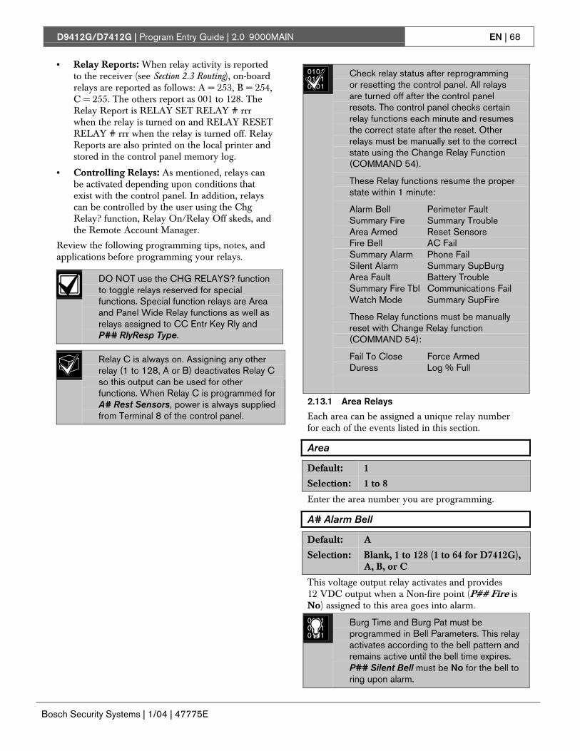
D9412G/D7412G | Program Entry Guide | 2.0 9000MAIN EN | 68
Bosch Security Systems | 1/04 | 47775E
• Relay Reports: When relay activity is reportedto the receiver (see Section 2.3 Routing), on-boardrelays are reported as follows: A = 253, B = 254,C = 255. The others report as 001 to 128. TheRelay Report is RELAY SET RELAY # rrrwhen the relay is turned on and RELAY RESETRELAY # rrr when the relay is turned off. RelayReports are also printed on the local printer andstored in the control panel memory log.
• Controlling Relays: As mentioned, relays canbe activated depending upon conditions thatexist with the control panel. In addition, relayscan be controlled by the user using the ChgRelay? function, Relay On/Relay Off skeds, andthe Remote Account Manager.
Review the following programming tips, notes, andapplications before programming your relays.
DO NOT use the CHG RELAYS? functionto toggle relays reserved for specialfunctions. Special function relays are Areaand Panel Wide Relay functions as well asrelays assigned to CC Entr Key Rly andP## RlyResp Type.
Relay C is always on. Assigning any otherrelay (1 to 128, A or B) deactivates Relay Cso this output can be used for otherfunctions. When Relay C is programmed forA# Rest Sensors, power is always suppliedfrom Terminal 8 of the control panel.
010101010101
Check relay status after reprogrammingor resetting the control panel. All relaysare turned off after the control panelresets. The control panel checks certainrelay functions each minute and resumesthe correct state after the reset. Otherrelays must be manually set to the correctstate using the Change Relay Function(COMMAND 54).
These Relay functions resume the properstate within 1 minute:
Alarm Bell Perimeter FaultSummary Fire Summary TroubleArea Armed Reset SensorsFire Bell AC FailSummary Alarm Phone FailSilent Alarm Summary SupBurgArea Fault Battery TroubleSummary Fire Tbl Communications FailWatch Mode Summary SupFire
These Relay functions must be manuallyreset with Change Relay function(COMMAND 54):
Fail To Close Force ArmedDuress Log % Full
2.13.1 Area Relays
Each area can be assigned a unique relay numberfor each of the events listed in this section.
Area
Default: 1
Selection: 1 to 8
Enter the area number you are programming.
A# Alarm Bell
Default: A
Selection: Blank, 1 to 128 (1 to 64 for D7412G),A, B, or C
This voltage output relay activates and provides12 VDC output when a Non-fire point (P## Fire isNo) assigned to this area goes into alarm.
010101010101
Burg Time and Burg Pat must beprogrammed in Bell Parameters. This relayactivates according to the bell pattern andremains active until the bell time expires.P## Silent Bell must be No for the bell toring upon alarm.

D9412G/D7412G | Program Entry Guide | 2.0 9000MAIN EN | 69
Bosch Security Systems | 1/04 | 47775E
A# Fire Bell
Default: A
Selection: Blank, 1 to 128 (1 to 64 for D7412G),A, B, or C
This voltage output relay activates and provides12 VDC output when a Fire point (P## Fire is Yes)assigned to this area goes into alarm.
010101010101
Fire Time and Fire Pat must beprogrammed in Bell Parameters. This relayactivates according to the bell pattern andremains active until the bell time expires.P## Silent Bell must be No in order forthe bell to ring upon alarm.
010101010101
Although Relay C is a valid entry for A#Fire Bell, do not program Relay C for thisentry.
A# Reset Sensors
Default: C
Selection: Blank, 1 to 128 (1 to 64 for D7412G),A, B, or C
Unlike the default relay for Alarm Bell and Fire Bell,this voltage-output relay (Relay C) de-activates for 5seconds when the Reset Sensors? function isinitiated from the command center or during a FireWalk Test.
The Reset Sensor time converts from the5 second default time to the timeprogrammed in A# Verify Time (seeSection 2.9 Area Parameters) when apoint programmed for P## Alarm Verify(Section 4.1 Point Index) goes into analarm condition.
010101010101
When sharing one relay to reset sensors intwo or more areas, you must program thefollowing. Failure to do so causesTROUBLE PT ### for all point typesprogrammed as P## Resettable.
• CC # Scope must include all the areasthat are sharing the relay.
• L## Reset Sensors for the userinitiating the sensor reset must beenabled for all the areas that aresharing the relay.
• A# Verify Time must be the samenumber of seconds for all the areasthat are sharing the relay.
A# Fail to Close
Default: Blank
Selection: Blank, 1 to 128 (1 to 64 for D7412G),A, B, or C
Activates when the Closing Window expires for thespecified area. It remains activated until midnight, oruntil another Closing Window starts, or the controlpanel is reset, whichever occurs first.
See Programming Tip #5 in this sectionfor additional relay functions.
A# Force Armed
Default: Blank
Selection: Blank, 1 to 128 (1 to 64 for D7412G),A, B, or C
Activates when this area is Force Armed. It remainsactivated until the area is disarmed or the controlpanel is reset.
When perimeter force arming, this relaydoes not activate.
A# Watch Mode
Default: Blank
Selection: Blank, 1 to 128 (1 to 64 for D7412G),A, B, or C
Activates when a Controlled point programmed forP## Watch Point is tripped in the specified areawhile the area is in Watch Mode and the point is notarmed. It remains activated for 2 seconds after eachpoint is faulted.

D9412G/D7412G | Program Entry Guide | 2.0 9000MAIN EN | 70
Bosch Security Systems | 1/04 | 47775E
A# Area Armed
Default: Blank
Selection: Blank, 1 to 128 (1 to 64 for D7412G),A, B, or C
Activates when the specified area becomes masterarmed (exit delay must expire before the relayactivates). The relay remains activated until the areais disarmed. It does not deactivate during the entrydelay time.
If multiple areas use the same relay, the relayactivates when all areas are armed. It deactivateswhen the first area disarms.
Programming a 64 in Area 8’s Silent Alarmrelay causes the Area Armed relay toenergize at the beginning of the exit delaytime.
Keyswitch area armed status with LEDs.Use a D8129 Module and connect an LEDto display the armed state.
Alternate communication trigger: Thisoutput relay can be used to trigger theinput zone of a device being used as aslave to report control panel arming status.
A# Area Fault
Default: Blank
Selection: Blank, 1 to 128 (1 to 64 for D7412G),A, B, or C
The relay activates whenever a controlled (P##Type 1, 2, 3 only) Perimeter or Interior point isfaulted. The relay remains activated until allPerimeter and Interior points in the area are normal.
Keyswitch area armed status with LEDs.Use a D8129 Module and connect an LEDto light when this relay is activatedindicating that the area is not ready to arm.
A# Duress Relay
Default: Blank
Selection: Blank, 1 to 128 (1 to 64 for D7412G),A, B, or C
The relay activates when a Duress alarm isgenerated from a command center assigned to thespecified area.
010101010101
Burg Time needs a bell periodprogrammed and A# Duress Enable mustbe Yes. This relay activates steadilyregardless of bell pattern and remainsactive until the bell time expires.
A# Perim Fault
Default: Blank
Selection: Blank, 1 to 128 (1 to 64 for D7412G),A, B, or C
The relay activates when a Controlled Perimeterpoint (P## Type 1) assigned to the specified area isfaulted. This relay activates regardless of the areasarmed state. This relay provides a steady output untilall Perimeter points in the area return to normal.
This relay does not activate on interiorfaults. To detect all area point faults,program all points as Perimeter points inthe area where this relay is assigned.
A# Silent Alarm
Default: Blank
Selection: Blank, 1 to 128 (1 to 64 for D7412G),A, B, or C
This relay activates when a point assigned to thespecified area and programmed for P## Silent Bellgoes into alarm.
010101010101
Programming Tip #1: Burg Time needs abell period programmed. This relayactivates according to the bell pattern andremains active until the bell time expires ora valid passcode is entered.
010101010101
Programming Tip #2: Programming 64 inArea 8’s Silent Alarm Relay causes theArea Armed or Perimeter Armed Relay(see Programming Tip #5) to energize atthe beginning of the exit delay time.
010101010101
Programming Tip #3: Programming anon-zero value in Area 5’s Silent AlarmRelay enables Ground Fault Detect on theD9412G or D7412G Control Panels. Seethe D9412G/D7412G Operation andInstallation Guide regarding Ground FaultDetect.

D9412G/D7412G | Program Entry Guide | 2.0 9000MAIN EN | 71
Bosch Security Systems | 1/04 | 47775E
010101010101
Programming Tip #4:
Fire Trouble Resound was added tofirmware versions 6.20 and later. Thisfeature, when enabled, resounds the FireTrouble condition at 12:00 PM or 12:00AM if the Fire Trouble condition still exists.It does not, however, retransmit the FireTrouble condition at the specified time.The Fire Trouble Event is only sent, ifprogrammed to do so, at the time itoccurs.
• To disable the Fire Trouble Resoundfeature, program a 0 in Area 6’s SilentAlarm Relay entry.
• To enable the Fire Trouble Resoundfeature at 12:00 PM, program a 61 inArea 6’s Silent Alarm Relay entry.
• To enable the Fire Trouble Resoundfeature at 12:00 AM, program a 62 inArea 6’s Silent Alarm Relay entry.
Note:
Programming a value other than 0, 61, or 62enables the Fire Trouble Resound feature at12:00 AM.
Beginning in Firmware version 6.30 andhigher, a Fire Trouble Resound promptwas added to Section 6.7 Miscellaneous.This prompt operates as described.
010101010101
Programming Tip #5:
Perimeter Armed Relay was added tofirmware versions 6.20 and later. Thisfeature, when enabled, turns the Fail toClose Relay function into a PerimeterArmed Relay function.
To switch the Fail to Close Relay into aPerimeter Armed Relay function, programa 63 in Area 7’s Silent Alarm Relay entry.Then, program a relay number into theappropriate area you wish to activate whenthe area becomes Perimeter Armed(COMMAND 2, COMMAND 3, orCOMMAND 8). See Programming Tip #2for additional information.
2.13.2 Panel-Wide Relays
The following eleven relay options activate whenthey occur anywhere in the control panel. They arenot restricted by area boundaries.
AC Failure
Default: Blank
Selection: Blank, 1 to 128 (1 to 64 for D7412G),A, B, or C
Activates when the control panel responds to an ACpower failure as programmed in AC Fail Time inSection 2.5 Power Supervision. This relay automaticallyresets when AC power is restored.
Use this relay as an option to createaudible annunciation using the commandcenters for all applications excludingcommercial fire systems.
Battery Trouble
Default: Blank
Selection: Blank, 1 to 128 (1 to 64 for D7412G),A, B, or C
Activates when battery voltage falls below 85% ofcapacity (12.1 VDC) for a fully charged (13.8 VDC)battery, or when the battery is in a missingcondition. This relay automatically resets whenbattery power is restored.
Use this relay as an option to createaudible annunciation using the commandcenters for all applications excludingcommercial fire systems.
Phone Fail
Default: Blank
Selection: Blank, 1 to 128 (1 to 64 for D7412G),A, B, or C
Activates when a telephone line failure occurs. Atime must be entered in Ph Supv Time (see Section2.2 Phone Parameters) for this relay to activate. Thisrelay automatically resets upon restoral of the phoneline(s).

D9412G/D7412G | Program Entry Guide | 2.0 9000MAIN EN | 72
Bosch Security Systems | 1/04 | 47775E
Comm Fail
Default: Blank
Selection: Blank, 1 to 128 (1 to 64 for D7412G),A, B, or C
This relay activates when a control panel is unableto communicate a report after making ten attemptsto each routing destination. At the same time, COMMFAIL RT ## displays at the command center. Thisrelay automatically resets when a report is sentsuccessfully.
Use this relay to report primary digitalreport failure to an alternatecommunication device.
Log % Full
Default: Blank
Selection: Blank, 1 to 128 (1 to 64 for D7412G),A, B, or C
Enter the number of the relay that activates whenthe log reaches the programmed percentage of itscapacity as programmed in RAM Parametersprogram item Log % Full. This relay provides asteady output until a Get Log and Set Pointer isperformed from the RPS.
Summary Fire
Default: Blank
Selection: Blank, 1 to 128 (1 to 64 for D7412G),A, B, or C
Enter the number of the relay that activates whenany Fire point in the system (P## Type 0, P## FireYes) goes into alarm. This relay provides a steadyoutput until all Fire points in the system are returnedto normal.
Summary Alarm
Default: Blank
Selection: Blank, 1 to 128 (1 to 64 for D7412G),A, B, or C
Enter the relay’s number that activates when a Non-fire point goes into alarm. This relay provides asteady output until the alarm is acknowledged by avalid passcode then cleared from alarm memorywith an acknowledgment at the command center.
This relay does not activate for silentalarms.
Summary Fire Tbl
Default: Blank
Selection: Blank, 1 to 128 (1 to 64 for D7412G),A, B, or C
This relay activates when any Fire point in thecontrol panel is in trouble, or if a Fire Supervisionpoint is missing. This relay provides a steady outputuntil all Fire points restore to a normal condition.
Summary SupFire
Default: Blank
Selection: Blank, 1 to 128 (1 to 64 for D7412G),A, B, or C
Activates when any Fire Supervisory point in thecontrol panel is in a supervisory condition (offnormal). This relay provides a steady output until allFire Supervisory points are restored to a normalcondition.
Summary Trouble
Default: Blank
Selection: Blank, 1 to 128 (1 to 64 for D7412G),A, B, or C
Activates when any Non-fire point in the controlpanel is in a trouble condition. This relay provides asteady output until the user at the command centeracknowledges the trouble.
Summary SupBurg
Default: Blank
Selection: Blank, 1 to 128 (1 to 64 for D7412G),A, B, or C
Activates when any Non-fire Supervisory point inthe control panel is in a supervisory condition, or if aSupervisory Burg point is missing. This relayprovides a steady output until it is acknowledged atthe command center.
D9412G/D7412G | Program Entry Guide | 3.0 RADXUSR1/RADXUSR2 EN | 73
Bosch Security Systems | 1/04 | 47775E
3.0 RADXUSR1/RADXUSR23.1 Passcode/Token WorksheetThese programming items assign user groups 001 to249 a passcode, area assignment by authority level,and a User Group Window.
010101010101
Two handlers in the D5200 Programmer areused to program the users. RADXUSR1Handler programs users 000 to 124.RADXUSR2 programs users 125 to 249(D9412G only).
3.1.1 User Groups
For the D9412G, there are 249 groups (99 groups forthe D7412G) consisting of one user with a passcodeand token, (master) and three users withtokens/cards but not a passcode (sub-user). All usersin the group share the same authority level as themaster user.
3.1.2 Passcodes
Only the master user is assigned a passcode. Thepasscode can be three to six digits. Entering threedigits in User ### chooses the master user.Programming the U### Passcode assigns apasscode to the master user. Sub-users cannot usethe passcode. While the system allows tokens/cardsto be added to USER 0 (service passcode), thetokens/cards do not function because the servicepasscode uses Authority Level 15.
3.1.3 User Group Window
Use U### User Group to enable/disable theU### Passcode for up to eight different timeperiods throughout the day. Assign the number (1 to8) programmed in U### User Group to a UserWindows #. If the user is outside a window,COMMAND DISABLED appears on the commandcenter after the user enters the passcode and presses[ENTER].
This window does not affect tokens/cards, itonly affects the passcode of the masteruser.
3.1.4 Authority Level by Area
A user group is assigned an authority level of 1through 14 for each area using the U### Area #Auth prompt. The authority level can be differentfor each area. Not programming an authority levelfor an area is indicated by the NOT AUTHORIZEDdisplay on the command center.
When using the Add/Change User functionat the command center, the authority levelsand the changes made affect the masteruser’s passcode and the entire group’stoken/cards.
When using the ACCESS CTL LVL functionat the command center, the whole group isaffected by whether the level is on or off foraccess control functions only.
When using the DELETE USER? function,the whole group is deleted. There is nomeans to delete each user within the groupindividually. It is recommended that you usethe ADD/CHG USER? function to change auser token/card instead of deleting thewhole group.
3.1.5 User Name
Each user group can be assigned one U### Name.This name is logged and reported to the centralstation for all the users in the group. The user ID isused to differentiate which user’s token/card wasexecuted.
Beginning with v6.30, when using a D1260Command Center, User 249 text is usedfor contact information text (such astelephone numbers). If a D1260 is installedon the system, do not use User 249 foruser ID information.
3.1.6 Tokens/Cards
The master user assigned the passcode can also beassigned a token/card. This is done by programmingthe U### Mstr Site and U### Mstr C/D.
Three more token/cards are assigned to the usergroup for sub-users using the U### SU# Site andU### SU# C/D.
3.1.7 Reporting and Logging
Modem Format must be Yes for the followingreports to the central station. Regardless of thereporting format, they log and print at the localprinter as shown. Each sub-user is identified by themaster user’s three-digit number plus an extension of0, 1, 2, or 3. These numbers are called Sub-user IDCodes.
Figure 3 shows all the users for User Group 122 asthey would appear.

D9412G/D7412G | Program Entry Guide | 3.0 RADXUSR1/RADXUSR2 EN | 74
Bosch Security Systems | 1/04 | 47775E
Figure 3: User Group 122 Example
Master User:
ID 122.
♦ CRD ID 122-0
♦ Sub User -1: ID 122-1CRD ID 122-1
♦ Sub User -2: ID 122-2.CRD ID 122-2
♦ Sub User -3: ID 122-3.CRD ID 122-3
2
1
1 - User passcode2 - User token/card
010101010101
In reporting systems using modem format, all three digits of the User ID Code are transmitted to thecentral station with appropriate reports. Central station automation computer systems may only acceptZonex and COMEX style User Ids. See Point/User Flag in Section 2.1 Phone.
In BFSK, only one number is transmitted. This number represents a group of ten users as shown in Table 28.Users 100 through 249 do not report in BFSK format.
Table 28: BSFK User Code Report
User Code000 to 009
User Code010 to 019
User Code020 to 029
User Code030 to 039
User Code040 to 049
User Code050 to 059
User Code060 to 069
User Code070 to 079
User Code080 to 089
User Code090 to 099
BFSKReport
0
BFSKReport
1
BFSKReport
2
BFSKReport
3
BFSKReport
4
BFSKReport
5
BFSKReport
6
BFSKReport
7
BFSKReport
8
BFSKReport
9
User ###
Default: 001
Selection: 000 or 001 to 249 (001 to 099 for theD7412G)
Enter the User number you are programming.
010101010101
User 000 is the Service Authority Level(Level 15). You cannot change theprogramming for user 000.
Only the Service Authority Level (User000) can delete User 000. When a userother than User 000 tries to delete thepasscode for User 000, the commandcenter displays NOT IN USE.
User 000 cannot be added/changed at thecommand center whether it exists or not.
U### Passcode
Default: See Program Record Sheet
Selection: Three to six digits ( 0 to 9)
Enter three to six digits to enable a passcode for themaster user in this group.
010101010101
User I.D.000 is the Service Passcode. Thedefault Service Passcode is 123.
The programmer does not allow you toenter any passcode number that couldconflict with a duress passcode. If DuressType is a 1, passcodes within a range of 1for existing passcodes cannot be entered.This rule applies even if duress is disabled.For example, once a passcode of 654321is entered, 654322, 654323, 654320,and 654329 cannot be entered.

D9412G/D7412G | Program Entry Guide | 3.0 RADXUSR1/RADXUSR2 EN | 75
Bosch Security Systems | 1/04 | 47775E
A silence bell authority is built into allauthority levels, even if they are the defaultand none of the available programmablefunctions are enabled. A user passcodecan silence a Fire/Burg bell as long as anyauthority level is assigned to the areawhere the bell can be silenced.
U### User Group
Default: Blank
Selection: Blank, 1 to 8
Use this parameter to create a group of up to 249users (99 for the D7412G) whose combinations canbe enabled/disabled using an automatic userwindow. This is the number entered into the W#User Group for any active W# User Window.Multiple windows can be programmed for one usergroup (up to eight) within one 24-hour period. Forexample, if User Group 1 has a window runningfrom 8:00 AM (start time) to 4:00 PM (stop time),the users for that group may use their passcodes onlybetween that time. Between 4:00 PM that day and8:00 AM the next day, the users may not use theirpasscodes.
010101010101 To enable this user’s passcode at all times,
leave U### User Group blank.
User Group Window times cannot be changed fromthe command center. Once a window is assigned toa user group, the users in that group rely on thewindow to be active (within the start and stop times)for their passcodes to function. The only way todisable the window is by reprogramming the controlpanel from the D5200 or RAM.
U### Area 1 [through Area 8] Auth
Default: See Program Record Sheet
Selection: 1 to 14 or Blank
Assign an authority level to the user for this area.
Blank means the user has no authority in this area.
U### Name
Default: See Program Record Sheet
Selection: Sixteen alphanumeric characters
Enter Alphabetic-characters A to Z in capital letters
Period (.), comma (,), percent (%), parentheses [()],equal (=), greater/less than (<>), exclamation (!),braces ({}), apostrophe (’), carat (^), grave accent (`),tilde (~), semi-colon (;), and colon (:) are notallowed.
Enter up to sixteen characters of text for this usergroup.
Programming this group with adepartmental, team, or function nameidentifies all the users in this group in afunction related manner, such asENGINEERING.
Card Data Format
The D9412G/D7412G and D9210B Controllercomply with the 26-BIT Wiegand card data format.In essence, the format consists of 26 bits (3.2 bytes)of data. The first bit is used for the even parity. Thenext 8 bits (first byte) is used for the U### SiteCode. The next 16 bits (second and third byte) areused for the U### Card Data. The last bit is usedfor the odd parity.
As long as the reader and tokens/cards you are usingare 26-BIT Wiegand compatible, they function withthis system.
Use only the readers identified as being compatiblewith the D9210B door control module. Informationon these readers can be found in the D9210B O/IManual.
For more information, see the Security IndustryAssociation (SIA) Access Control 26-BIT WiegandReader Interface Standard.
U### Mstr Site
Default: Blank
Selection: 000 = (0) to 254 or Blank (255)
Master User ### Site Data
Enter the first three decimal numbers on the back ofthe token/card. This is the first byte (bits 2 through9) of data for a 26-bit Wiegand card. This is calledthe site number. Tokens/cards with a site code of255 are not compatible with the D9412G/D7412GControl Panels.

D9412G/D7412G | Program Entry Guide | 3.0 RADXUSR1/RADXUSR2 EN | 76
Bosch Security Systems | 1/04 | 47775E
010101010101
Converting hexadecimal to decimal: Ifyour card label contains letters as well asnumbers, the number is hexadecimal.*Convert the hexadecimal number todecimal using your calculator. If you cannotconvert in this way, use the reader and theAdd/Chg User? Function to add thetokens/cards.
Perform the following test to confirm youcan convert properly:
Use 319EB0 as the hexadecimal number.On your calculator, press [HEX]. Enter allthe hexadecimal characters into thecalculator. Press [DEC] and yourhexadecimal characters convert to thefollowing eight digits: 03251888. The sitenumber is 032. Enter it in U### MstrSite. Your card data is 51888. Enter it intoU### Mstr C/D.
* A hexadecimal number can contain allnumerals. If the code does not work tryconverting the number fromhexadecimal to decimal.
Always tag your tokens before addingthem to the system so you do not mix themup. Use the CRD ID ###-# number toindex them.
U### Mstr C/D
Default: Blank
Selection: 00000 = (0) to 65534 or Blank (65535)
Master User ### Card Data
Enter the remaining five decimal numbers on theback of the token/card. This is the second and thirdbyte (bits 10 through 25) of data for a 26-bitWiegand card. This is called the card data.
You must program U### Mstr Site beforeprogramming this prompt.
U### SU1 through SU3 Site
Default: Blank
Selection: 000 = (0) to 254 or Blank (255)
Sub-users one through three Site Data.
U### SU1 through SU3 C/D
Default: Blank
Selection: 00000 = (0) to 655354 or Blank(65535)
Sub-users one through three card data.

D9412G/D7412G | Program Entry Guide | 4.0 RADXPNTS EN | 77
Bosch Security Systems | 1/04 | 47775E
4.0 RADXPNTS4.1 Point IndexUse this programming module to constructpersonality types for points used in the system. TheIndex numbers are used in Point Assignments. Eachunique point index number determines the controlpanel’s responses to specific conditions occurring onthe Protective points.
The NEW RECORD program contains defaultentries and descriptions that match RPS defaults forpoint indexes. See the D9412G/D7412G ProgramRecord Sheet for defaults.
Point Index
Default: 1
Selection: 1 to 31
The number of the point personality you areprogramming. You can define up to 31 individualpersonalities.
P## Type
Default: See Program Record Sheet
Selection: 0 to 9
P ##Type
Description
0 24-hour: A 24-hour point is not turned on and off from a command center. 24-hour points arearmed all the time, and can be used for fire protection (see the P ## Fire Point prompt in Section4.1.1 Point Responses), panic, medical, and police alerts.
24-hour points can be programmed as bypassable. Consider the application carefully before usingthe bypassable option. Bypassable 24-hour points should be programmed to Buzz on Fault.
When a 24-hour point is bypassed, send the report as it occurs. If the area contains all 24-hourpoints, the area is never armed or disarmed. A Deferred Bypass Report is not sent.
24-hour protection for fire doors, roof hatches, and so on. Instead of programming this type ofprotection as a 24-hour point, consider using a Perimeter point type with a Point Response of 9 to E.24-hour points do not show faults when an arming function is entered, but Perimeter points do.When programming this type of protection, consider also using the Buzz on Fault and Local WhileDisarmed options.
1 Perimeter: Perimeter points are armed with all Arming functions. Points programmed as perimetercan also be armed as a group (using Perimeter-Arming functions) separately from pointsprogrammed as interior. This lets the user partially arm the system to establish Perimeter protectionwhile occupying the interior of the protected premises.
Perimeter points can be programmed to initiate entry delay time. If the point initiates entry delay, itcan also initiate an entry tone.
When a Perimeter point is programmed for entry delay, entry delay time is always provided. If thearea is in entry delay when a second Perimeter point trips, the control panel compares the remainingentry delay time to the time programmed for the second Perimeter point. If the second Perimeterpoint’s entry delay time is less than the remaining time, it shortens the entry delay time.
Perimeter points programmed for an instant point response, generate an alarm immediately whentripped, even during entry or exit delay.
D9412G/D7412G | Program Entry Guide | 4.0 RADXPNTS EN | 78
Bosch Security Systems | 1/04 | 47775E
P ##TypeSelection
Description
2 Interior: Interior points are armed only by master arming the area. They are NOT armed whenusing Perimeter Arming functions. These points are typically used to monitor interior detectiondevices such as interior doors, motion detectors, photoelectric beams, and carpet mats.
Instant Interior Points: Interior points are usually programmed for an instant alarm (see Section4.1.1 Point Responses). Points programmed for instant alarms generate alarms immediately, evenduring entry or exit delay.
Delayed Interior Points: Interior points can be programmed for a delayed point response. Adelayed response means that if the point is tripped while the area is armed, it initiates entry delay. Itdoes not generate an alarm until entry delay expires.
When an Interior point is programmed for entry delay, entry delay time is always provided. If thearea is in entry delay when the Interior point trips, the control panel compares the remaining entrydelay time to the time programmed for the Interior point. If the Interior point’s entry delay time isless than the remaining time, it shortens the entry delay time.
Delayed points can also initiate an entry tone at the command center (see the P## Ent Tone Offprompt in Section 4.1.1 Point Responses).
In some cases, you may need to create an Interior point that causes an instant alarm only if entrydelay protection is not tripped first. Use Interior Follower to create this type of protection.
3 Interior Follower: Interior Follower points are armed only by master arming the area. They areNOT armed when using Perimeter-Arming functions.
An Interior Follower point does not create an alarm if it trips while the area is in entry delay. AnInterior Follower does not change the amount of remaining entry delay time.
If no entry delay is in effect when the Interior Follower trips, it creates an instant alarm.
You must program a delayed Point Response (4, 5, 6, 7, or 8) for an Interior Follower point. Thecontrol panel ignores the entry in P## Entry Delay for an Interior Follower point.
Note:It may be necessary to increase the debounce count for Interior Follower points to prevent Interior Followerpoints from going into alarm before the control panel recognizes that a Perimeter Delay point was faulted.Program the Interior Follower’s debounce for one number higher than the debounce count on Perimeter delay

D9412G/D7412G | Program Entry Guide | 4.0 RADXPNTS EN | 79
Bosch Security Systems | 1/04 | 47775E
P ##Type
Description
Keyswitch Maintained: Program Point Response as 1. Do not connect initiating devices to aKeyswitch point.
Normal: The area is disarmed.
Short: When this point changes from normal to open, the area arms.
Open: A short is a trouble when the area is disarmed. A short is an alarm when the area isarmed. When this point changes from shorted to normal or open, it restores.
Program Point Response as 2, the point responds as follows:
Normal: When this point changes from open to normal, the area arms.
Open: The area is disarmed.
Short: A short is a trouble when the area is disarmed. A short is an alarm when the area isarmed. When this point changes from shorted to normal or open, it restores.
4*
Trouble and Restoral Reports are not sent if Local While Disarmed is Yes.
Alarm and Restoral Reports are not sent if Local While Armed is Yes.
Keyswitch Momentary: Used for area arming and disarming. Point Response must beprogrammed 1. Do not connect initiating devices to a Keyswitch point.
N→S→N: When this point momentarily changes from normal to shorted to normal, it togglesthe armed state of the area.
Open: An open is a trouble while the point is disarmed. An open is an alarm while thepoint is armed.
When this point changes from open to normal, it restores.
5*
Trouble and Restoral Reports are not sent if Local Disarmed is Yes.
Open/Close Point: Used for point arming and disarming. Point Response must be programmed 1.Local bells are silenced through the command center.
Normal: The point is armed and sends a Point Closing Report. A Point Closing Report is notsent if Local Armed is Yes.
Open: An open is an alarm when the point is armed. An open is a trouble when the pointis disarmed. Alarm and Restoral Reports are not sent if Local Disarmed is Yes.
6*
Short: The point is disarmed and sends a Point Opening Report. A Point Opening Reportis not sent if Local Armed is Yes.
* Keyswitch Points. Special rules apply to points used for Keyswitch functions. These special point types do not respondthe same way to the point response entry as Point Types 1, 2, and 3. Responses for keyswitch point types are described inSection 4.1.1 Point Responses.

D9412G/D7412G | Program Entry Guide | 4.0 RADXPNTS EN | 80
Bosch Security Systems | 1/04 | 47775E
P ##TypeSelection
Description
D279 (O/C Non-Priority): The D279 provides point arming and disarming independent of the areaarm state. A non-priority D279 point arm state does not affect the area arm state. Point Responsemust be programmed 1. Local bells are silenced through the command center. For bell control at theD279, use P## Type 8.
Cut the W1 jumper on the D279 to send Point Opening and Point Closing Reports. If the D279’sW1 jumper is not cut, no Open or Close Report is sent, regardless of control panel programming.
Normal: The point is armed and sends a Point Closing Report. Point Closing Report is notsent if Local Armed is Yes.
Open: The point is disarmed and sends a Point Opening Report. A Point Opening Reportis not sent if Local Armed is Yes.
7*
Short: A short is an alarm when the point is armed. A short is a trouble when the point isdisarmed. Alarm and Restoral Reports are not sent if Local Disarmed is Yes.
D279 (O/C Priority): The D279 provides point arming and disarming independent of the area armstate. A priority D279 point must be armed before an area can be armed. Program Point Responseas 2.
Cut the W1 jumper on the D279 to send area Opening and Closing Reports as programmed in AreaParameters and to provide bell control. If the D279’s W1 jumper is NOT cut then no Area Open orArea Close Report is sent, and alarm bells can only be silenced from a command center, no matterhow the control panel is programmed.
Normal: When this point changes from open to normal, the area arms.
Open: The area is disarmed. The alarm bell silences if an alarm occurred while the areawas armed.
8*
Short: A short is a trouble while the area is disarmed. A short is an alarm while the area isarmed. When this point changes from shorted to normal or open, it restores.
9* Easikey: This point is programmed for access. Program Point Response as 1. If the system isMaster Armed or Perimeter Armed (with or without delays), presenting a valid token to the Easikeyreader shorts the point and disarms its assigned area. Presenting a valid token in a Disarmed statedoes not clear trouble or alarm memory or rearm the area.
* Keyswitch Points. Special rules apply to points used for Keyswitch functions. These special point types do not respondthe same way to the point response entry as Point Types 1, 2, and 3. Responses for keyswitch point types are described inSection 4.1.1 Point Responses.

D9412G/D7412G | Program Entry Guide | 4.0 RADXPNTS EN | 81
Bosch Security Systems | 1/04 | 47775E
4.1.1 Point Responses
Applications for Point Responses 9, D,and E:
Combine Point Responses 9, D, and E withPerimeter point types to create more flexible24-hour protection. Unlike 24-hour points, afaulted Perimeter point with a PointResponse of D and E displays at thecommand center when arming. Like a 24-hour point, a point programmed this way cangenerate alarms whether the area is armedor disarmed.
Combining Point Response 9 with the LocalWhile Disarmed feature provides off-sitereporting when the area is armed, but onlylocal alarm annunciation when the area isdisarmed.
Combining Point Response 9 with the LocalWhile Armed feature provides off-sitereporting when the area is disarmed, butonly local alarm annunciation when the areais armed.
Point Response E: Use this for Zonex/Asicmotion detectors. The control panel canreport troubles while Master Armed.
Point Response F: Does not sound at localcommand centers but activates RlyRespType 1 and command center faults. Toannunciate the off-normal state at acommand center, program Disp as Dvc asYes and/or BuzzOn Fault as 1 or 2. Thispoint response does not generate alarms oractivate an alarm relay.
Point Response 8, 9, A, B, and C providesupervisory (24-hour) reporting.
Characteristics of a Fire Point:
Reporting: When a group of events occur,the control panel routes and prints out FireReports first.
Visual Annunciation: Fire troubles continueto scroll until the trouble is cleared. Onceacknowledged, FIRE TROUBLE scrolls tolet the end user know that a Fire point, orgroup of Fire points, is still in trouble. Panel-Wide Relays, Summary Fire, andSummary Fire Tbl activate if a relay isassigned when any Fire point goes intoalarm or is in trouble.
Audible Annunciation: A Fire pointactivates the A# Fire Bell relayprogrammed in Relay Parameters. Theamount of time and pattern of the relayactivation is programmed by area in BellParameters, A# Fire Time, and A# FirePat.
Supervisory: A Fire point can send a FireSupervisory Report and activate theSummary Fire, Sup and Summary FireTbl, Panel-Wide Relays with a P##Response of 8-9-A-B-C.
Alarm Verification: A Fire point can delayan alarm by the time programmed in A#Verify Time in the Area Parameters.Combined with A# Resettable, a Fire pointalso resets the electrical circuit for the verifytime amount.
Reset Sensor: A fire device that requiresresetting can be manually reset using thereset sensor relay for the area it is assignedto.
Fire Walk: Use the Fire Walk function totest Fire points in the system.
To provide an audible tone for a restoredFire Supervisory point, use P## RlyRespType 1 and connect to a graphicannunciator.
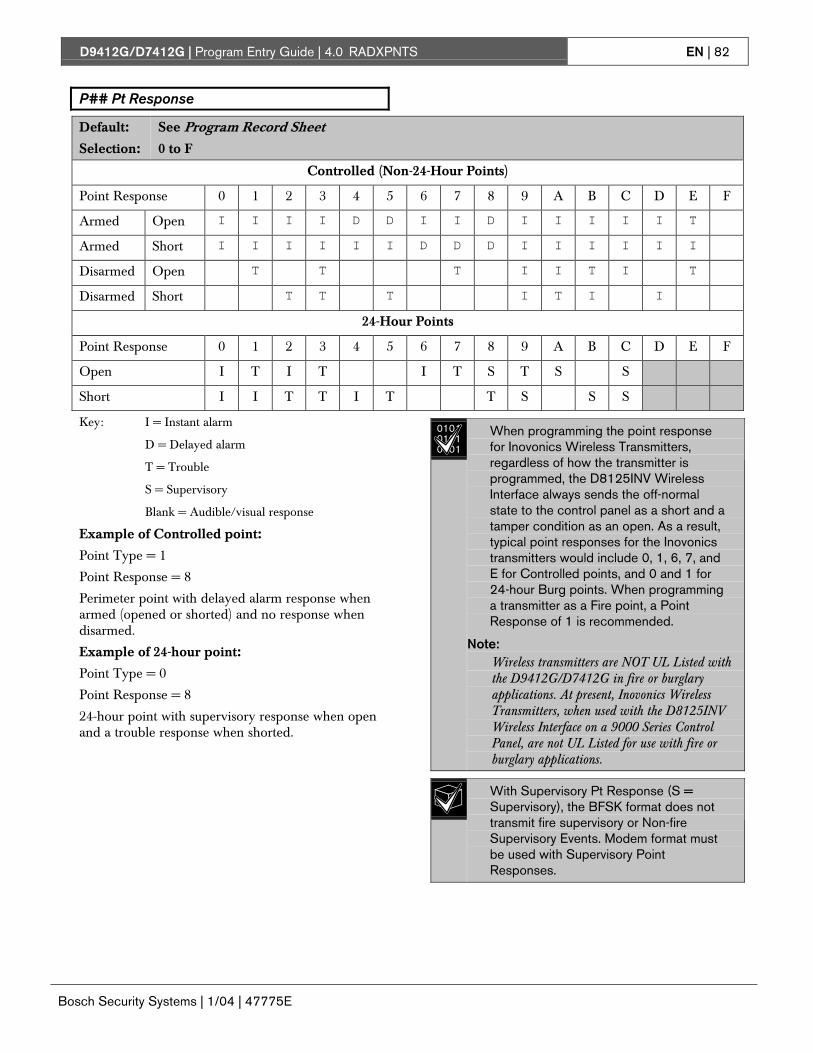
D9412G/D7412G | Program Entry Guide | 4.0 RADXPNTS EN | 82
Bosch Security Systems | 1/04 | 47775E
P## Pt Response
Default: See Program Record Sheet
Selection: 0 to F
Controlled (Non-24-Hour Points)
Point Response 0 1 2 3 4 5 6 7 8 9 A B C D E F
Armed Open I I I I D D I I D I I I I I T
Armed Short I I I I I I D D D I I I I I I
Disarmed Open T T T I I T I T
Disarmed Short T T T I T I I
24-Hour Points
Point Response 0 1 2 3 4 5 6 7 8 9 A B C D E F
Open I T I T I T S T S S
Short I I T T I T T S S S
Key: I = Instant alarm
D = Delayed alarm
T = Trouble
S = Supervisory
Blank = Audible/visual response
Example of Controlled point:
Point Type = 1
Point Response = 8
Perimeter point with delayed alarm response whenarmed (opened or shorted) and no response whendisarmed.
Example of 24-hour point:
Point Type = 0
Point Response = 8
24-hour point with supervisory response when openand a trouble response when shorted.
010101010101
When programming the point responsefor Inovonics Wireless Transmitters,regardless of how the transmitter isprogrammed, the D8125INV WirelessInterface always sends the off-normalstate to the control panel as a short and atamper condition as an open. As a result,typical point responses for the Inovonicstransmitters would include 0, 1, 6, 7, andE for Controlled points, and 0 and 1 for24-hour Burg points. When programminga transmitter as a Fire point, a PointResponse of 1 is recommended.
Note:Wireless transmitters are NOT UL Listed withthe D9412G/D7412G in fire or burglaryapplications. At present, Inovonics WirelessTransmitters, when used with the D8125INVWireless Interface on a 9000 Series ControlPanel, are not UL Listed for use with fire orburglary applications.
With Supervisory Pt Response (S =Supervisory), the BFSK format does nottransmit fire supervisory or Non-fireSupervisory Events. Modem format mustbe used with Supervisory PointResponses.

D9412G/D7412G | Program Entry Guide | 4.0 RADXPNTS EN | 83
Bosch Security Systems | 1/04 | 47775E
P## Entry Delay
Default: See Program Record Sheet
Selection: 5 seconds to 600 seconds
Use this option to enter the amount of entry delaytime that a user has after faulting a Controlled point(P## Type 1, 2, 3) with a delayed response (D)(P## Pt Response) of 4, 5, 6, 7, or 8. DISARM NOWdisplays for the duration of the time programmedwhen the point is faulted in the delay condition.
010101010101
Beginning with firmware revision 6.30and higher, the D1255 alternatesbetween DISARM NOW and the point textof the point that caused the area to gointo entry delay.
If this time expires before disarming, or if the pointis faulted to an instant response (I), an alarm occurs.
010101010101
Make entries in 5 second increments. Theprogrammer does not allow off-incremententries.
If another Perimeter or Interior FollowerDelay point trips while the area is alreadyin entry delay, the control panel adjusts thedelay time to the Delay point with the leastamount of delay time.
Use P## Type 3 Interior Follower toprogram points that do not go into instantalarm the user must fault in order to get tothe command center and disarm duringthe entry or exit delay period.
P## Ent Tone Off
Default: No
Selection: Yes or No
Yes Disable entry delay tone when thispoint is faulted to the delay response.
No A tone sounds at command centerswhen this point initiates entry delay.
This option enables/disables the entry delay warningtone for this point.
Do not set points to No if they are actuallyused to notify the user to disarm thesystem. The possibility of false alarmsincreases if the entry delay warning is notused.
010101010101
Entry Tone can also be turned off whenprogramming your CC Entry Tone, inSection 2.10 Command Center, whichallows you to manage the tone bycommand center.
You may want to disable the entry tone inhigh security applications where you donot want to annunciate entry delay.
P## Silent Bell
Default: No
Selection: Yes or No
Yes Activate the Silent Alarm relay whenthis point goes into alarm. Commandcenters do not sound the alarm tonefor Non-fire points.
No Activate either the Fire Bell relay orAlarm Bell relay and sound the alarmtone at command centers when thispoint goes into alarm. If this is a Firepoint, it activates the Fire Bell relayprogrammed in Relay Parameters.Otherwise, it activates the Alarm Bellrelay. The amount of time and patternof the relay activation is programmedby area in Bell Parameters.
If you want this point to eventually ring thebell because the message failed to reachthe central station receiver, program P##Audible After 2 Failures as Yes.
P## Ring Til Rst
Default: No
Selection: Yes or No
Yes The relay programmed to provide firealarm output for this point cannot bede-activated until the point restores tonormal.
No The relay programmed to provide firealarm output for this point can be de-activated before the point restores tonormal.
Use this option to determine if the bell continues toring until the Fire Bell time expires. The pointreturns to a normal condition when the useracknowledges the alarm to silence the bell.

D9412G/D7412G | Program Entry Guide | 4.0 RADXPNTS EN | 84
Bosch Security Systems | 1/04 | 47775E
If the point restores and the fire alarm isnot silenced from the command center,the fire alarm output continues until FireBell time expires. If the point does notrestore, the fire alarm output continueseven after bell time expires.
\
Use this option for fire applications to meetthe requirement that audible alarms cannotbe silenced until the fault condition clearsor the Fire Bell time expires.
P## Audible After 2 Failures
Default: No
Selection: Yes or No
Yes A# Burg Alarm relay activates after twofailed attempts.
No P## Silent points do not cause the A#Burg Alarm relay to activate even if thereport does not get to the centralstation receiver.
Use this option for reporting Non-fire pointsprogrammed as P## Silent to eventually cause thealarm bell to ring if the control panel fails to reportthe Alarm Event at the end of two failed attempts tothe remote central station receiver.
010101010101
When a point that is programmed for P##Silent Bell is faulted, the timer for the A#Burg Time starts, even though the bell isnot yet ringing. It can take up to 3 minutesbefore the second attempt fails. Ensure A#Burg Time is programmed to provide theamount of bell time you need, minus the 3minutes it can take before the bell actuallybegins to ring.
P## Invisible Pt
Default: See Program Record Sheet
Selection: Yes or No
Yes Command centers do not displayalarm activity from this point.
No Activity from this point is visible at thecommand centers.
Use this option to determine whether the pointappears in the command center display upon anAlarm condition. For LED command centers, theLED does not illuminate upon an alarm condition.Point text appears and annunciation is made forInvisible points programmed for a trouble conditionin point response.
To prevent the command center alarm toneand the A# Burg Alarm bell from sounding,this point needs P## Silence Bellprogrammed as Yes.
010101010101
ALARM SILENCED displays at thecommand center if this Invisible pointcauses a bell to ring upon an alarm and avalid passcode is entered.

D9412G/D7412G | Program Entry Guide | 4.0 RADXPNTS EN | 85
Bosch Security Systems | 1/04 | 47775E
P## Buzz On Fault
Default: Blank
Selection: Blank, 1 to 3
Selection Operation for Controlled Points
(Point Types 1, 2, and 3)
Operation for 24-hour Points
(Point Type 0)
Blank The point only generates a buzz at the commandcenter if it goes into the trouble conditionindicated in the P## Point Response.
Same
1 The point generates a Buzz Until Restore at thecommand center for any fault condition while thepoint is disarmed. The buzz continues until thepoint restores and the user acknowledges thecondition using a passcode or COMMAND 4.The point must be normal before the user cansilence the buzz.
The point generates a Buzz Until Restore at thecommand center for any fault condition regardlessof the armed state. The buzz continues until thepoint restores and the user acknowledges thecondition using a passcode or COMMAND 4.The point must be normal before the user cansilence the buzz.
2 The point generates a buzz at the commandcenter for any fault condition when the point isdisarmed. The point does not need to be normalbefore the user can silence the buzz.
The point generates a buzz at the commandcenter for any fault condition regardless of the armedstate. The point does not need to be normalbefore the user can silence the buzz.
3 The point generates a buzz at the commandcenter for any fault condition when the area isdisarmed. The user cannot silence this buzz, butit silences automatically when the point isrestored. If the fault condition results in a troubleresponse, the command center continues to buzzeven after the user acknowledges the condition ifthe fault is still present.
The point generates a buzz at the commandcenter for any fault condition regardless of thearmed state. The user cannot silence this buzz,but it silences automatically when the point isrestored. If the fault condition results in a troubleresponse, the command center continues to buzzeven after the user acknowledges the condition ifthe fault is still present.
The buzz does not automatically stop oncethe point is restored when using Option 1 or2. The user must acknowledge the buzzprior to the buzz stopping. However, whenusing Option 3, the buzz automatically stopswhen the point restores to normal withoutuser intervention.
Points bypassed (by the user, Sked,Swinger Bypass, or RAM) do not generate aBuzz On Fault condition at the commandcenter.
P## Watch Point
Default: See Program Record Sheet
Selection: Yes or No
Yes This point activates Watch Moderesponses if it is faulted while thecontrol panel is in Watch Mode.
No Do not activate Watch Mode responsesfor this point.
Use this option to allow a Controlled point togenerate a watch tone as long as the area is disarmedand not being faulted into a trouble or alarmcondition.

D9412G/D7412G | Program Entry Guide | 4.0 RADXPNTS EN | 86
Bosch Security Systems | 1/04 | 47775E
P## RlyResp Type
Default: See Program Record Sheet
Selection: Blank, 1 to 2
Blank Point state does not affect the operationof the corresponding relay.
1 Relay Follow Point: The relaycorresponding with this point activateswhen the point is faulted to any offnormal condition. The relayautomatically resets when the point isreturned to normal.
2 Relay Latches: The relaycorresponding with this point latcheswhen the point goes into an alarmcondition. This relay provides a steadyoutput until the alarm is acknowledgedby a valid passcode then cleared fromalarm memory with anacknowledgment at the commandcenter.
Use this option to cause a relay (1 to 127 forD9412G; 1 to 64 for D7412G) to respond when acorresponding point with the same number (1 to127) is faulted. [This requires connecting D8129OctoRelays to Zonex Bus 1 and/or Zonex Bus 2(D9412G only). See address settings on the back ofthe D9412G/D7412G Program Record Sheet (P/N:47488)].
Point 128 is reserved for other use than anactual point. Only the first 127 points canhave an associated relay. Relays are notavailable for Points 129 to 247.
Do not use the Chg Relays? function totoggle relays reserved for specialfunctions. Special function relays are Areaand Panel Wide Relay functions as well asrelays assigned to CC Entr Key Rly andP## RlyResp Type.
P## Disp as Dvc
Default: No
Selection: Yes or No
Yes Display CHECK DEVICE when thispoint is off normal.
No Do not display CHECK DEVICE whenthis point is off normal.
Use this option to cause the command center todisplay CHECK DEVICE once a point is off normalor was acknowledged after going into alarm.
Use this function for devices with a drycontact output which faults a point oncethe device is in a trouble condition.
P## Local While Disarmed
Default: See Program Record Sheet
Selection: Yes or No
Yes Suppress Alarm, Trouble and Restoral*Reports from this point while the areait is assigned to is disarmed.
No Report events occurring from thispoint while the area is disarmed.
* Restoral Reports are still transmitted if the alarm,trouble, or bypass (by Sked, RAM, or Swinger bypass)condition occurred when the area disarmed, and thepoint restored.
Use this option to allow a Controlled point (P##Type 1, 2, 3), to report Alarms, Troubles, andRestoral Reports only when the area is armed. Thisprompt does not affect local annunciation.
Local While Disarmed suppresses allreports from 24-hour points. Do not useP## Type 0 for this prompt. Rememberthat this only works for Disarmed points,and a Type 0 is a 24-hour Always Armedpoint. Instead, choose any type other than0, and use a point response that reportsan alarm whether the point is armed or not.For instance, P## Type 1 and P##Response 9 reports an alarm on an openor a short (I) whether the area is armed ornot.
Local While Disarmed affects Keyswitchpoints. This prompt suppresses keyswitch(troubles/restorals) and D279(alarms/troubles/restorals). Do not use thisparameter for these applications.
P## Local While Armed
Default: No
Selection: Yes or No
Yes Suppress Alarm, Trouble and Restoral*Reports from this point while the areait is assigned to is armed.
No Report events occurring from thispoint while the area is armed.

D9412G/D7412G | Program Entry Guide | 4.0 RADXPNTS EN | 87
Bosch Security Systems | 1/04 | 47775E
* Restoral Reports are still transmitted if the alarm,trouble, or bypass (by Sked, RAM, or Swinger bypass)condition occurred when the area disarmed, and thepoint restored.
Allows a controlled point (P## Type 1, 2, 3), toreport Alarms, Troubles, and Restoral Reports onlywhen the area is disarmed. This prompt does notaffect local annunciation.
Local While Armed suppresses all reportsfrom 24-hour points. Do not use P## Type0 for this prompt. This only works fordisarmed points. Type 0 is a 24-houralways armed point. Choose any Typeother than 0, and use a point responsethat reports an alarm whether the point isarmed or not. For instance, P## Type 1and P## Response 9 reports an alarm ona trouble or a short whether the area isdisarmed or not.
Local While Armed affects KeyswitchPoints. This prompt suppresses keyswitch(alarms/troubles/restorals) and D279(opening/closing/troubles/restorals). Donot use this parameter for controlledpoints that arm/disarm.
P## Disable Rst
Default: No
Selection: Yes or No
Yes Enable Restoral Reports form thispoint.
No Disable Restoral Reports from thispoint.
* Restoral Reports are still transmitted if the alarm,trouble, or bypass (by sked, RAM, or Swinger bypass)condition occurred when the area disarmed, and thepoint restored.
Use this option to disable any Restoral Reports fromthis point after it returns to normal from an alarm ortrouble condition.
P## FA Retrnable
Default: No
Selection: Yes or No
Yes This point automatically returns to thesystem when it restores to normal.
No This point stays out of the system untilthe area is disarmed.
Use this option to allow points that were forcearmed out of the area to return back to the armedstate once they become normal again without havingto disarm the system.
Use on loading dock doors, which must beleft open until loading is completed. Oncethe loading dock door is closed, the pointdetects any subsequent opening andreports an alarm.
P## BP Retrnable
Default: No
Selection: Yes or No
Yes This point automatically returns to thesystem when the area is disarmed.
No This point stays out of the systemthrough arming and disarming cycles.
Use this option to return a point that was bypassed,force armed, or swinger bypassed back into thesystem once the area this point is assigned to isdisarmed.
Turn this item to No for Interlock points.
When the point cannot return to thesystem through disarming, the point mustbe manually unbypassed using theUnbypass?, command center function,Sked Functions 4 and 5 or remotelyunbypassed using RAM.
010101010101
For Force Armed points to remainbypassed, ensure P## FA Retrnable isNo.

D9412G/D7412G | Program Entry Guide | 4.0 RADXPNTS EN | 88
Bosch Security Systems | 1/04 | 47775E
P## Bypassable
Default: No
Selection: Yes or No
Yes This point can be bypassed and forcearmed.
No This point cannot be bypassed or forcearmed from the command center orRAM. However, it can be force armedby automatic arming at the end of theClosing Window (see the A# AutoClose prompt in Section 2.9.5Open/Close Options) or by a Skedprogrammed to arm the area.
Use this option to allow this point to be bypassedand/or force armed.
Bypassing a 24-hour point: When a 24-hour pointor 24-hour Supervisory point is bypassed, 24 HOURBYPASS continuously scrolls at the commandcenter. 24 HOUR BYPASS scrolls to indicate a 24-hour Non-fire point, P## Fire No is bypassed. FIREBYPASS scrolls to indicate a 24-hour Fire point or aFire Supervisory point is bypassed.
Alternative to a 24-hour Point: For alarmcapability of a 24-hour point without thecontinuous scrolling, use a Perimeterpoint with a Point Response of 9 to E.
010101010101
A point can be bypassed at the commandcenter using the BYPASS? function,which reports as a Command Bypass.When bypassed by Sked Function 3, thereport is Sked Bypass. When bypassed byRAM a RAM Bypass reports after RAMdisconnects. When swinger shunted, aSwinger Shunt is reported. If the point isnot bypassable, it cannot be bypassed inany of the above cases.
Programming Bypassable as Yes forCross points may cause missed Cross-Point alarms. For example, if Points 1 and2 were programmed as Cross points andPoint 1 was Bypassed or Force Armed,Point 2 cannot generate an Alarm CrossPoint Event. Point 2 may, however,generate an Unverified or Alarm Eventdepending on how the point was tripped.Be careful when using this feature withCross point applications.
P## Swinger Byps
Default: No
Selection: Yes or No
Yes Enable Swinger Bypass for this point.
No Disable Swinger Bypass for this point.
Use this option to allow the control panel toautomatically bypass a point that erroneously reportsfour Alarm or Trouble Events within an hour of thefirst event.
The control panel reports a Swinger Bypass P###upon the fourth report. If the point has a partialcount (less than four events during an hour), thecount is reset to zero and three more events arerequired upon the next report before the controlpanel initiates the bypass.
010101010101
P## Bypassable does not need to beprogrammed Yes for swinger bypass towork.
A Swinger Shunted point returns to thesystem if P## BP Returnable? is Yes. Ifnot, return the point to the system asdescribed in the application note for P##BP Returnable.
P## Report Bypass at Occurrence
Default: No
Selection: Yes or No
Yes Send a Command Bypass Report atthe time the point is bypassed.
No Do not send a Command BypassReport at the time the point isbypassed.
This option allows a point to generate a CommandBypass Report as soon as a user bypasses the pointfrom the command center. This option should beenabled for all Bypassable 24-hour points. You mayalso elect to report a bypassed point at the time thearea is armed. See P## Defer BP Report.

D9412G/D7412G | Program Entry Guide | 4.0 RADXPNTS EN | 89
Bosch Security Systems | 1/04 | 47775E
P## Defer BP Report
Default: No
Selection: Yes or No
Yes Send a Point Bypass Report with theClosing Report instead of a CommandBypass Report when a user bypassesthe point.
No Do not defer Bypass Reports.
Use this option to prevent (P## Type 0 to F) pointsthat are bypassed by the user (COMMANDBYPASS) from occurring until the area is armed.Once the area is armed, the bypassed points and anypoint being bypassed during the arming sequencereport as POINT BYPASS along with the ClosingReport.
010101010101
Bypass Reports do not occur when armingthe area if the Closing Report issuppressed by O/C Windows or are notreported.
Bypass Reports for 24-hour points do notreport If P## Report Bypass atOccurrence and P## Defer BypassReport are both No.
To report the bypass at occurrence andwhen the area is armed, program P##Report Bypass at Occurrence and P##Defer Bypass Report as Yes. ACommand Bypass Report is sent as soonas it occurs and a Point Bypass Report issent with the Closing Report.
P## Cross Point
Default: No
Selection: Yes or No
Yes This point is a Cross point.
No This point is not a Cross point.
The Cross point function is available onlyin Firmware revisions 6.30 and higher.
Do not use Cross points for Fire points.
The Cross point feature is available only on pointsprogrammed as having an Instant point response.Also, Controlled points (Point Types 1, 2 and 3) donot follow the Cross point operation (described asfollows) during entry or exit delay.
The Cross point option is designed to reduce falsealarms. To achieve this, points can be programmedso the control panel must see an alarm conditionwithin a programmed period of time (called CrossPoint Time) from at least two points within a CrossPoint Group before Cross Point Alarm Events aregenerated. These points need the Cross point optionenabled in their corresponding point indexes to beable to generate this event. See Section 6.8 Cross PointParameters for additional programming requirementsto program the Cross Point Timer.
Cross Point Groups were established in the D9412Gand D7412G to support the Cross Point function.There are 31 Cross Point Groups in the D9412Gand ten in the D7412G. Each Cross Point Groupconsists of eight points and is identified by the pointnumbers in them (such as, Cross Points 1 to 8, CrossPoints 9 to 16, and so on).
The Cross point function only applies toAlarm conditions. It does not apply toTrouble or Supervisory conditions.
D9412G/D7412G | Program Entry Guide | 4.0 RADXPNTS EN | 90
Bosch Security Systems | 1/04 | 47775E
P## Fire Point
Default: No
Selection: Yes or No
Yes This point is a Fire point.
No This point is not a Fire point.
Use this option to make a 24-hour point a Fire point.This option makes this point the highest priorityevent in the control panel when an alarm occurs forboth reporting and displaying on the commandcenter.
Characteristics of a Fire Point
Reporting: When a group of eventsoccur, the control panel routes and printsout Fire Reports first.
Visual Annunciation: FIRE TROUBLEScontinues to scroll until the trouble iscleared. Once acknowledged, a FIRETROUBLE scroll lets the end user knowthat a Fire point, or group of Fire points, isstill in trouble. Panel Wide Relays,Summary Fire, and Summary Fire Tblactivates if a relay is assigned when anyFire point goes into alarm or is in trouble.
Audible Annunciation: A Fire pointactivates the A# Fire Bell relayprogrammed in Relay Parameters. Theamount of time and pattern of the relayactivation is programmed by area in BellParameters, A# Fire Time, and A# FirePat.
Supervisory: A Fire point can send a FireSupervisory Report and activate theSummary Fire Sup and Summary FireTbl Panel Wide Relays with a P##Response of 8-9-A-B-C.
Alarm Verification: A Fire point can delayan alarm by the time programmed in A#Verify Time in the Area parameters.
Reset Sensor: A fire device that requiresresetting can be manually reset using thereset sensor relay for the area where it isassigned.
Fire Walk: Fire points can be tested in thesystem using the Fire Walk Test whichautomatically resets each point for fiveseconds when it is tripped and rings theFire Bell for two seconds.
You should dedicate a fire annunciationdevice to all your Fire points if they areassigned to a single area in a multiple areasystem. Special red command centers andannunciators with specific keys for firesystems are designed for this type ofapplication (D1256 and D1257).
Do not use the Cross point function forFire points.
D9412G/D7412G | Program Entry Guide | 4.0 RADXPNTS EN | 91
Bosch Security Systems | 1/04 | 47775E
P## Alarm Verify
Default: See Program Record Sheet
Selection: Yes or No
Yes Enable alarm verification on this point.
Alarm verification points must beprogrammed as resettable.
No Disable alarm verification on thispoint.
Use this option only with Fire points to designatethem for alarm verification.
When an Alarm Verification point goes into alarm,the control panel removes power to all Resettablepoints for the duration programmed in A# VerifyTime in Section 2.9 Area Parameters. If the point (oranother Resettable point in the area) is still in alarm,or goes back into alarm within 60 seconds after theinitial verification time reset, an alarm is generated.
During a Fire Walk Test the reset time is 5seconds. The time programmed in A#Verify Time is ignored. Use the Crosspoint function for Fire points.
P## Resettable
Default: See Program Record Sheet
Selection: Yes or No
Yes This point is reset by the Reset Sensor?function and during the alarmverification sequence.
No This point is not resettable.
Use this option if this is a Powered point thatrequires interruption of power to reset a latchedalarm condition. The Resettable point option istypically used with smoke detectors and glass breakdetectors.
When initiated (either through a Fire Walk Test orthe command center’s Reset Sensor? Function) orwhen the RAM interrupts power to the device for 5seconds, Sensor Reset is reported to the centralstation receiver.
When a sensor reset is initiated, thecontrol panel does not accept alarms fromany points with P## Resettableprogrammed as Yes. During the 5-secondreset time, alarms from these points areignored.
Do not mix fire and intrusion devices onthe same powered loop.
4.2 Point AssignmentsThese entries assign point indexes to Points 1 to 127,129 to 247 for the D9412G and Points 1 to 75 for theD7412G, and assigns the points to the areas. Alsoincluded in this section are parameters used to setthe point’s debounce count, BFSK/Relay (for usewhen transmitting in BFSK or assigning relays tofollow alarms for a group of points), and customcommand center and report text for each point.
Point Number
Default: 1
Selection: 1 to 127, 129 to 247
Enter the point number you are programming.When transmitting in Modem IIIa2, the three-digitpoint number is reported to the D6500/D6600.When transmitting in BFSK, you must assign a zonenumber in BFSK/Relay.
010101010101 Point numbers 128 and 248 are reserved
for Zonex bus 1 and 2 supervision.

D9412G/D7412G | Program Entry Guide | 4.0 RADXPNTS EN | 92
Bosch Security Systems | 1/04 | 47775E
P### Point Index
Default: See Program Record Sheet
Selection: Blank (00) to 31
This entry selects one of the 31 P## Index codesthat define the point’s characteristics and determineshow the control panel responds to various pointconditions.
Blank (00) disables the point.
Missing Point Reports occur if a pointaddress does not exist for a point assigneda point index. Extra Point Events occur ifmore than two devices have the sameaddress.
When a POPIT is missing, the control panelgenerates the following responses basedon the point type:
• Fire points generate missing troubleresponses.
• Non-fire 24-hour points generatemissing alarm responses.
• Non-fire, non 24-hour points generatemissing alarm responses while armed,and trouble responses while disarmed.Exception: Non-fire, non-24-hour pointswith a point response of 9 to Dgenerate a missing alarm responsewhile disarmed.
POPIT modules monitor their sensor loopsfor three conditions: loop normal, loopopen, and loop shorted. They report thesethree conditions to the control panel. Thecontrol panel uses point programming tointerpret the sensor loop informationreported by the POPITs and to make theappropriate system response.
P### Area Assign
Default: 1
Selection: 1 to 8
The areas are numbered 1 to 8. Select the areanumber to which the point is assigned.
P### Debounce
Default: 2
Selection: 1 to 15
1 .300 seconds
2 .600 seconds
3 .900 seconds
4 1.2 seconds
5 1.5 seconds
6 1.8 seconds
7 2.1 seconds
8 2.4 seconds
9 2.7 seconds
10 3.0 seconds
11 3.3 seconds
12 3.6 seconds
13 3.9 seconds
14 4.2 seconds
15 4.5 seconds
The debounce count is the number of times thecontrol panel scans a point before initiating analarm. Scan cycles are 300 ms.
For appropriate settings consult the manufacturer’sinstructions for the device connected to this point.
010101010101
Bosch Security Systems recommends anentry of two or higher. Interior Followerpoints need a debounce of at least three.
Door points assigned to D9210B modulesneed a debounce of at least four.

D9412G/D7412G | Program Entry Guide | 4.0 RADXPNTS EN | 93
Bosch Security Systems | 1/04 | 47775E
P### BFSK/Relay
Default: See Program Record Sheet
Selection: 0 to 9
Use this option to:2. Determine the point number reported in BFSK
when this point is tripped.3. Activate a relay when the point goes into an
alarm condition, even if the control panel isprogrammed for Modem reporting as shown inTable 29.
BFSK/Relays do not activate for FireSupervisory or Non-Fire Supervisorypoints.
Table 29: P### BFSK/Relay Codes/Relays
Trips Relay
BFSK Code
D8129 on ZonexBus 2 forD9412G*
D8129 on ZonexBus 2 forD7412G*
1 73 92 74 103 75 114 76 125 77 136 78 147 79 158 80 16
* Address setting = 1 (on), 2 (off), 3 (on), 4 (on)
Local annunciation on the commandcenters and Local Printer reporting andthe View Log display the actual pointnumber (1 to 247), not the BFSK reportcode
010101010101
Do not assign a BFSK/Relay to Invisiblepoints. To avoid triggering a BFSK/Relay,program this prompt as 0.
On the D9412G, do not use relays 73through 80 for Area or Panel-Wide Relayfunctions when using BFSK relays. Doingso prevents the BFSK relays fromtriggering.
On the D7412G, do not use relays 9through 16 for Area or Panel Wide Relayfunctions when using BFSK relays. Doingso prevents BFSK relays from triggering.
Two relays can activate when this pointgoes into alarm if the P## Rly Resp Typefor this point is programmed.
Use these codes to activate relays on theD8129 OctoRelay (or C8137 TransmitterInterface). You can assign the same codeto several points providing a summaryzone alarm output. When the point goesinto alarm, the relay activates. When thealarm is acknowledged and is no longerscrolling in the command center display,the relay resets.
P### Point Text
Default: See Program Record Sheet
Selection: Up to sixteen alphanumericcharacters
Enter alphabetic characters (A to Z) in capital letters.
Enter up to sixteen characters of text to describe thepoint. This point text is displayed at commandcenters, if the point is programmed as visible, andreported to the D6500/D6600 when transmitting inRadionics Modem IIIa2 format (if it is a reportingpoint).
Include the point number in custom point text. Thishelps the user when viewing events, initiatingbypasses, and so on. It can also simplifytroubleshooting.
When a D1260 Command Center isinstalled on the system, the point text forPoints 240 to 247 can be used for AreaName Text for Areas 1 to 8, respectively.See Table 30:
Table 30: Point Text for Points 240 to 247
Point Text Corresponding Area Name TextPoint 240 Area 1Point 241 Area 2Point 242 Area 3Point 243 Area 4Point 244 Area 5Point 245 Area 6Point 246 Area 7Point 247 Area 8

D9412G/D7412G | Program Entry Guide | 4.0 RADXPNTS EN | 94
Bosch Security Systems | 1/04 | 47775E
4.3 COMMAND 7 and COMMAND 9These entries assign point indexes, BFSK reportcode, BFSK relay that trips, and the text for theCOMMAND 7 and COMMAND 9 commandcenter functions.
CMD7 Point Index
Default: 31
Selection: Blank (00) to 31
This entry selects one of the 31 P## Index codesthat define how the control panel reacts when aCOMMAND 7 is initiated.
010101010101
The point index code used for COMMAND7 must not be used for any other points onthe system.
If the point index for COMMAND 7 hasFire points programmed Yes, this causesaccess control doors to unlock if FireUnlock is also programmed Yes (see theD9210B Program Entry Guide).
CMD7 BFSK/Relay
Default: 1
Selection: 0 to 9
Selects one of the digits shown for reporting in BFSKor for activating relays 73 to 80 (on the D9412G) orrelays 9 to 16 (for the D7412G) when COMMAND7 is initiated (see the P### BFSK/Relay prompt inSection 4.2 Point Assignments).
COMMAND 7 does not activate theSummary Fire Alarm relay.
CMD7 Point Text
Default: [COMMAND][7]
Selection: Up to sixteen alphanumericcharacters
Enter alphabetic characters A to Z in capital letters
Enter up to sixteen characters of text to describe thepoint. This point text is displayed at commandcenters (if the point is programmed as visible) andreported to the D6500/D6600 when transmitting inRadionics’ Modem IIIa2 format (if it is a reportingpoint).
CMD9 Point Index
Default: 31
Selection: Blank (00) to 31
This entry selects one of the 31 P## Index codesthat define how the control panel reacts when aCOMMAND 9 is initiated.
010101010101
The point index code used for COMMAND9 must not be used for any other points onthe system.
If the point index for COMMAND 9 hasFire points programmed as Yes, thiscauses access control doors to unlock ifFire Unlock is also programmed Yes (seethe D9210B Program Entry Guide).
CMD9 BFSK/Relay
Default: 1
Selection: 0 to 9
This entry selects one of the digits shown forreporting in BFSK or for activating relays 73 to 80(on the D9412G) or relays 9 to 16 (for the D7412G)when a COMMAND 9 is initiated (see the P###BFSK/Relay prompt in Section 4.2 Point Assignments).
COMMAND 9 does not activate theSummary Fire Alarm relay.
CMD9 Point Text
Default: [COMMAND][9]
Selection: Up to sixteen alphanumericcharacters
Enter alphabetic characters (A to Z) in capital letters
Enter up to sixteen characters of text to describe thepoint. This point text is displayed at commandcenters (if the point is programmed as visible) andreported to the D6500/D6600 when transmitting inRadionics’ Modem IIIa2 format (if it is a reportingpoint).

D9412G/D7412G | Program Entry Guide | 5.0 RADXSKED EN | 95
Bosch Security Systems | 1/04 | 47775E
5.0 RADXSKED5.1 WindowsUse this programming module to define thewindows for Opening and Closing and User Access.
5.1.1 Opening and Closing
Use these windows to set a schedule for disarmingand arming. The disarming and arming schedulesprovide several independent features:
• Suppress normal Opening and/or ClosingReports when A# Disable O/C in Windows isprogrammed Yes.
• Generate a Fail to Open Report if the area is notdisarmed on schedule when A# Fail To Openis programmed Yes.
• Provide a warning tone and a PLEASE CLOSENOW display at the command center when it istime to arm the area.
• Generate a Fail to Close Report if the area is notarmed on schedule when A# Fail To Close isprogrammed Yes.
• Automatically arm the area at the end of theClosing Window when A# Auto Close isprogrammed Yes.
Opening and closing schedules can be set upindependently. For example, if you only want to usefeatures provided by Closing Windows, leave timesblank in the Opening Windows prompts andprogram Closing Window times.
A worksheet is provided at the end of this section foryour convenience. Following the worksheet areexamples of how to program Opening and ClosingWindows for particular applications (see Table 35through Table 39.
About the Program Record Sheet: A columnlabeled Sked # is found on the Program Record Sheetprovided with the control panel. These numbersappear in D6500/D6600 reports and local printerreports when the window Begin Time executes.
Window selections 1 through 8 correspond with oddnumbered Skeds 41 through 55 for Open Windowand correspond with even numbered Skeds 42through 56 for Close Window. For example, whenthe Opening Window for Window 1 executes, aSked 41 Executed Event is generated. See Table 31.
Table 31: Window Selections
Selection Sked # Window Sked # Window
1 41 Open 42 Close2 43 Open 44 Close3 45 Open 46 Close4 47 Open 48 Close5 49 Open 50 Close6 51 Open 52 Close7 53 Open 54 Close8 55 Open 56 Close
Window
Default: 1
Selection: 1 to 8
Enter the window number you want to program.
W# Sunday
Default: No
Selection: Yes or No
Yes Activate this window on Sundays.
No Do not activate this window onSundays.
This prompt, and the next six day of the weekprompts, select the days of the week the Openingand/or Closing Windows are active.
Exceptions:
To prevent the windows from activating on certaindays of the year, program Xept Holiday Yes, andenable at least one Holiday Index. When XeptHoliday is Yes, the window executes on the days ofthe week programmed unless the Holiday Indexdesignates the date as a holiday.
If Opening and/or Closing Windows are onlyneeded on certain days of the year, do not programthe windows to execute on any days of the week.Instead, program Xept Holiday No and select aHoliday Index with the days of the year you wantthe window to be active.

D9412G/D7412G | Program Entry Guide | 5.0 RADXSKED EN | 96
Bosch Security Systems | 1/04 | 47775E
W# Monday
Default: No
Selection: Yes or No
W# Tuesday
Default: No
Selection: Yes or No
W# Wednesday
Default: No
Selection: Yes or No
W# Thursday
Default: No
Selection: Yes or No
W# Friday
Default: No
Selection: Yes or No
W# Saturday
Default: No
Selection: Yes or No
W# Open Early Begin
Default: 00:00
Selection: HH:MM (hours and minutes)
00:00 to 23:59
Open Early Begin: This program item is one ofthree required to create an Opening Window. Tofinish programming an Opening Window, OpenWindow Start and Open Window Stop must beprogrammed.
Use Open Early Begin to set the time the controlpanel looks for an Opening Window. WhenOpening and Closing Reports are enabled,disarming the area between midnight and the OpenEarly Begin time generates an Opening Report. Inaddition:
• If Disable O/C in Window is Yes: Disarmingthe area between the Open Early Begin and theOpen Window Start time generates an Early toOpen Event (if the Open Early Begin time is thesame as the Open Window Start time, the Earlyto Open Event is not sent).Disarming the area between the Open Window
Start and Open Window Stop time creates alocal event in the Panel log but does not sendthe Opening Report to the central station.
Disarming the area after the Open Window Stopand the next window’s Open Early Begin time(or midnight, whichever comes sooner)generates a Late to Open Event.
• If Disable O/C in Window is Yes: Disarmingthe area generates an Opening Report withoutthe early or late modifier, regardless of when thearea is disarmed.
When you are programming multiple windowsto activate on a single day, program thewindows in chronological order. Be careful notto program a window’s Open Early Begin timefor a time that is between any other window’sOpen Window Start and Open Window Stoptime.
010101010101 Do not program a window to cross the
midnight boundary.
Disabled windows have a blank begin time. If theentry for this prompt is blank, but times areprogrammed for Open Window Start and OpenWindow Stop, the window is disabled.
To disable the window, both the hours and minutesspaces must be Blank.
00:00 is midnight, 23:59 is 11:59 PM. Make entriesusing a 24-hour clock (for example, 7:00 AM isentered as 07:00, 2:45 PM is entered as 14:45).
Disable/Restart the control panel to activate today’swindow. If you are programming a window thatmust activate on the same day you are programmingit, do a disable/restart after programming.
W# Open Window Start
Default: 00: 00
Selection: HH:MM (hours and minutes)
Enter the time you want the control panel to startthe Opening Window. The window goes into effectat the beginning of the minute.
00:00 is midnight, 23:59 is 11:59 PM. Make entriesusing a 24-hour clock (for example, 7:00 AM isentered as 07:00, 2:45 PM is entered as 14:45).
This program item is one of three required to createan Opening Window. To program an OpeningWindow, Open Early Begin and Open WindowStop must also be programmed. See the W# OpenEarly Begin prompt in this section for reportfeature explanations.

D9412G/D7412G | Program Entry Guide | 5.0 RADXSKED EN | 97
Bosch Security Systems | 1/04 | 47775E
W# Open Window Stop
Default: 00: 00
Selection: HH:MM (hours and minutes)
Enter the time you want the control panel to end theOpening Window. The window stops at the end ofthe minute.
00:00 is midnight, 23:59 is 11:59 PM Make entriesusing a 24-hour clock (for example, 7:00 AM isentered as 07:00, 2:45 PM is entered as 14:45).
This program item is one of three required to createan Opening Window. To program an OpeningWindow, Open Early Begin and Open WindowStart must also be programmed.
If the area is not disarmed by the time the OpenWindow Stop time expires, the control panelgenerates a Fail to Open Report if enabled in FailTo Open.
Opening Reports generated between the OpenWindow Start time and Open Window Stop timecan be suppressed by programming Disable O/C inWindow Yes. See the Open Early Begin promptfor other report feature explanations.
Do not use a time of 23:59 as a window stop timeunless another window begins on the next day at00:00.
010101010101 Fail to Open Reports are not sent for
windows that stop at 23:59.
Figure 4: Example Opening Window Timeline (using two Opening Windows on same day)
12
34
56
7
8
9
1 - Areas disarmed between midnight and 6 AMgenerate Opening Reports.
2 - Areas disarmed between 6 AM and 7 AMgenerate Early to Open Reports.
3 - If the area is disarmed between 7 AM and 8 AMregular Opening Reports are generated. If DisableO/C in Window is programmed Yes the OpeningReport is not transmitted to the central station.
4 - If the area is not disarmed by 8:01 AM, a Fail toOpen Event is generated if Fail to Open isprogrammed Yes in Opening and Closing Options.
5 - If the user disarms the area between 8:01 AM and12:59, PM a Late to Open Event is generated.
6 - Areas that are disarmed between 1 PM and 2 PMgenerate Early to Open Reports.
7 - If the area is disarmed between 2 PM and 3 PMregular Opening Reports are generated. If DisableO/C in Window is programmed Yes, the OpeningReport is not transmitted to the central station.
8 - If the area is not disarmed by 3:01 PM, a Fail toOpen Event is generated if Fail to Open isprogrammed Yes in Opening and Closing Options.
9 - If the user disarms the area between 3:01 PM and11:59 PM, a Late to Open Event is generated.

D9412G/D7412G | Program Entry Guide | 5.0 RADXSKED EN | 98
Bosch Security Systems | 1/04 | 47775E
Table 32: Programming for Two Same Day Opening Windows (see Figure 4)
Open Close
W# Day of WeekEarlyBegin Start Stop
EarlyBegin Start Stop
eXceptOn
HolidayHolidayIndex Area(s)
1 S M T W T F S 06: 00 07 : 00 08: 00 Yes / No 1 2 3 4 1 2 3 4 5 6 7 82 S M T W T F S 13 : 00 14 : 00 15 : 00 Yes / No 1 2 3 4 1 2 3 4 5 6 7 8
Do not program a single window to cross the midnight boundary. The window stop time must be later than thewindow start time. To program a window that effectively crosses the midnight boundary, you must program twowindows.
For example, to program windows for an area that opens between 11:30 PM and 12:30 AM, five days a week, usetwo windows as shown in Table 33.
Table 33: Programming to Link Two Days over Midnight
Open Close
W# Day of WeekEarlyBegin Start Stop
EarlyBegin Start Stop
eXceptOn
HolidayHolidayIndex Area(s)
1 S M T W T F S 22 : 00 23 : 30 23 : 59 Yes No 1 2 3 4 1 2 3 4 5 6 7 82 S M T W T F S 00 : 00 00 : 00 00 : 30 Yes No 1 2 3 4 1 2 3 4 5 6 7 8
W# Close Early Begin
Default: 00: 00
Selection: HH:MM (hours and minutes)
00:00 to 23:59
Close Early Begin: This program item is one ofthree required to create a Closing Window. To finishprogramming a Closing Window, Close WindowStart and Close Window Stop must be programmed.
Use Close Early Begin to set the time that you wantthe control panel to look for a Closing Window.When Opening and Closing Reports are enabled,arming the area between midnight and the CloseEarly Begin time generates a Closing Report. Inaddition:
• If Disable O/C in Window is Yes: Arming thearea between the Close Early Begin time andthe Close Window Start time generates aClosing Early Event (if the Close Early Begintime is the same as the Close Window Starttime, the Closing Early Event is not sent).
Arming the area between the Close WindowStart and Close Window Stop time creates alocal event in the Panel log but does not sendthe Closing Report to the central station.
Arming the area after the Close Window Stop andthe next window’s Close Early Begin time (ormidnight, whichever comes sooner) generates aClosing Late Event.
• If Disable O/C in Window is No: Disarmingthe area generates a Closing Report without theearly or late modifier, regardless of when thearea is armed.
When you are programming multiple windowsto activate on a single day, program thewindows in chronological order. Be careful notto program a window’s Close Early Begin timefor a time that is between any other window’sClose Window Start and Close Window Stoptime.
Disabled windows have a blank begin time. Ifthe entry for this prompt is blank, but times areprogrammed for Close Window Start and CloseWindow Stop, the window is disabled.
To disable the window, both the hours andminutes spaces must be blank.
00:00 is midnight, 23:59 is 11:59 PM. Makeentries using a 24-hour clock (for example, 7:00AM is entered as 07:00, 2:45 PM is entered as14:45).

D9412G/D7412G | Program Entry Guide | 5.0 RADXSKED EN | 99
Bosch Security Systems | 1/04 | 47775E
Disable/Restart the control panel to activatetoday’s window. If you are programming awindow that needs to activate on the same daythat you are programming it, do a disable/restartafter programming.
W# Close Window Start
Default: 00: 00
Selection: HH:MM (hours and minutes)
Enter the time that you want the control panel tostart the Closing Window. The window goes intoeffect at the beginning of the minute.
00:00 is midnight, 23:59 is 11:59 PM. Make entriesusing a 24-hour clock (for example, 7:00 AM isentered as 07:00, 2:45 PM is entered as 14:45).
This program item is one of three required to createa Closing Window. To program a Closing Window,Close Early Begin and Close Window Stop mustalso be programmed.
If the area is not armed when the Close WindowStart time comes, a warning tone sounds andPLEASE CLOSE NOW displays at the commandcenter. To temporarily silence the tone, press the[ESC] key on the command center. The warningtone restarts in 10 minutes if the area is not armed.
See the W# Close Early Begin prompt in thissection for report feature explanations.
W# Close Window Stop
Default: 00: 00
Selection: HH:MM (hours and minutes)
Enter the time that you want the control panel toend the Closing Window. The window stops at theend of the minute.
00:00 is midnight, 23:59 is 11:59 PM. Make entriesusing a 24-hour clock (for example, 7:00 AM isentered as 07:00, 2:45 PM is entered as 14:45).
This program item is one of three required to createa Closing Window. To program a Closing Window,Close Early Begin and Close Window Start mustalso be programmed.
If the area is not armed by the time the CloseWindow Stop time expires, the control panelgenerates a Fail to Close Report if enabled in Fail ToClose.
Closing Reports generated between the CloseWindow Start time and Close Window Stop timecan be suppressed by programming Disable O/C inWindow Yes. See the W# Close Early Beginprompt for other report feature explanations.
Do not use a time of 23:59 as a window stop timeunless the window continues on the next day at00:00. Fail to Close Reports are not sent, and theAuto Close feature does not work for windows thatstop at 23:59.
Do not program a single window to cross themidnight boundary. The window stop time must belater than the window start time. To program awindow that effectively crosses the midnightboundary, you must program two windows.
For example, to program windows for an area thatcloses between 11:30 PM and 12:30 AM, five days aweek, use two windows as shown in Table 34.
Table 34: W# Close Window Stop Programming Example
Open Close
W# Day of WeekEarlyBegin Start Stop
EarlyBegin Start Stop
eXceptOn
HolidayHolidayIndex Area(s)
1 S M T W T F S 22 : 00 23 : 30 23 : 59 Yes No 1 2 3 4 1 2 3 4 5 6 7 82 S M T W T F S 00 : 00 00 : 00 00 : 30 Yes No 1 2 3 4 1 2 3 4 5 6 7 8

D9412G/D7412G | Program Entry Guide | 5.0 RADXSKED EN | 100
Bosch Security Systems | 1/04 | 47775E
W# Xept Holiday
Default: No
Selection: Yes or No
Yes Do not activate this window onholidays.
To use this selection, the window mustbe programmed to activate on at leastone day of the week and a HolidayIndex must be enabled.
No A holiday does not prevent thiswindow from activating.
You also use this selection if Openingand/or Closing Windows are onlyneeded on certain days of the year. Donot program the windows to executeon any days of the week. Instead,program Xept Holiday No, and selectat least one Holiday Index with thedays of the year you want the windowto be active.
Determine if the window is disabled on holidays, oris active only on holidays.
To prevent the windows from activating on certaindays of the year, program Xept Holiday Yes, andenable at least one Holiday Index. When XeptHoliday is programmed Yes, the window executeson the days of the week programmed unless the dateis designated as a Holiday by the Holiday Index(es)selected.
Holiday Indexes for O/C Windows
You can enable up to four Holiday Indexes for usewith Opening/Closing Windows. Enable at least oneHoliday Index if W# Xept Holiday is programmedYes for this window, or if you want this window toactivate only on specific dates. Holidays areprogrammed in Section 5.3 Holiday Indexes.
W# Holiday 1
Default: No
Selection: Yes or No
Yes Use Holiday Index 1 with this window.
No Do not use Holiday Index 1 with thiswindow.
W# Holiday 2
Default: No
Selection: Yes or No
W# Holiday 3
Default: No
Selection: Yes or No
W# Holiday 4
Default: No
Selection: Yes or No
W# Area 1 [through 8]
Default: No
Selection: Yes or No
Yes Activate the window in the areanumber (#) specified.
No Disable the window in the areanumber (#) specified.
Eight separate program items determine whether aparticular window activates in each of the eight areasof the control panel.
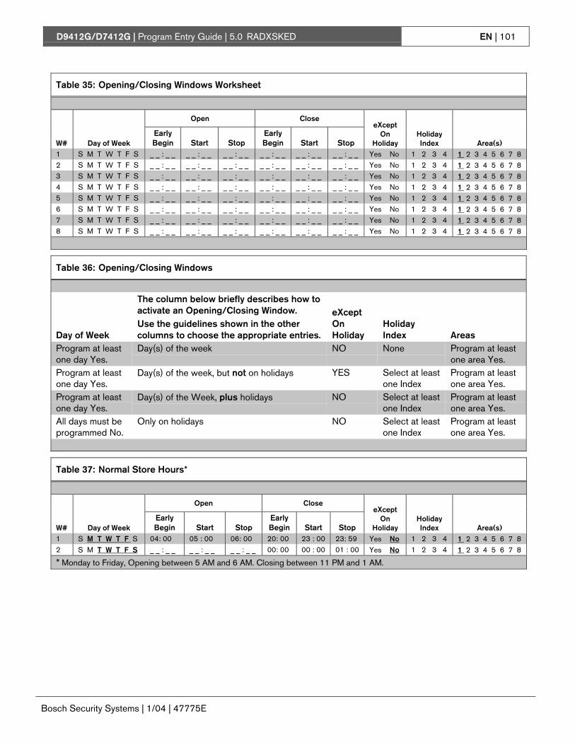
D9412G/D7412G | Program Entry Guide | 5.0 RADXSKED EN | 101
Bosch Security Systems | 1/04 | 47775E
Table 35: Opening/Closing Windows Worksheet
Open Close
W# Day of WeekEarlyBegin Start Stop
EarlyBegin Start Stop
eXceptOn
HolidayHolidayIndex Area(s)
1 S M T W T F S _ _ : _ _ _ _ : _ _ _ _ : _ _ _ _ : _ _ _ _ : _ _ _ _ : _ _ Yes No 1 2 3 4 1 2 3 4 5 6 7 82 S M T W T F S _ _ : _ _ _ _ : _ _ _ _ : _ _ _ _ : _ _ _ _ : _ _ _ _ : _ _ Yes No 1 2 3 4 1 2 3 4 5 6 7 83 S M T W T F S _ _ : _ _ _ _ : _ _ _ _ : _ _ _ _ : _ _ _ _ : _ _ _ _ : _ _ Yes No 1 2 3 4 1 2 3 4 5 6 7 84 S M T W T F S _ _ : _ _ _ _ : _ _ _ _ : _ _ _ _ : _ _ _ _ : _ _ _ _ : _ _ Yes No 1 2 3 4 1 2 3 4 5 6 7 85 S M T W T F S _ _ : _ _ _ _ : _ _ _ _ : _ _ _ _ : _ _ _ _ : _ _ _ _ : _ _ Yes No 1 2 3 4 1 2 3 4 5 6 7 86 S M T W T F S _ _ : _ _ _ _ : _ _ _ _ : _ _ _ _ : _ _ _ _ : _ _ _ _ : _ _ Yes No 1 2 3 4 1 2 3 4 5 6 7 87 S M T W T F S _ _ : _ _ _ _ : _ _ _ _ : _ _ _ _ : _ _ _ _ : _ _ _ _ : _ _ Yes No 1 2 3 4 1 2 3 4 5 6 7 88 S M T W T F S _ _ : _ _ _ _ : _ _ _ _ : _ _ _ _ : _ _ _ _ : _ _ _ _ : _ _ Yes No 1 2 3 4 1 2 3 4 5 6 7 8
Table 36: Opening/Closing Windows
Day of Week
The column below briefly describes how toactivate an Opening/Closing Window.Use the guidelines shown in the othercolumns to choose the appropriate entries.
eXceptOnHoliday
HolidayIndex Areas
Program at leastone day Yes.
Day(s) of the week NO None Program at leastone area Yes.
Program at leastone day Yes.
Day(s) of the week, but not on holidays YES Select at leastone Index
Program at leastone area Yes.
Program at leastone day Yes.
Day(s) of the Week, plus holidays NO Select at leastone Index
Program at leastone area Yes.
All days must beprogrammed No.
Only on holidays NO Select at leastone Index
Program at leastone area Yes.
Table 37: Normal Store Hours*
Open Close
W# Day of WeekEarlyBegin Start Stop
EarlyBegin Start Stop
eXceptOn
HolidayHolidayIndex Area(s)
1 S M T W T F S 04: 00 05 : 00 06: 00 20: 00 23 : 00 23: 59 Yes No 1 2 3 4 1 2 3 4 5 6 7 82 S M T W T F S _ _ : _ _ _ _ : _ _ _ _ : _ _ 00: 00 00 : 00 01 : 00 Yes No 1 2 3 4 1 2 3 4 5 6 7 8
* Monday to Friday, Opening between 5 AM and 6 AM. Closing between 11 PM and 1 AM.

D9412G/D7412G | Program Entry Guide | 5.0 RADXSKED EN | 102
Bosch Security Systems | 1/04 | 47775E
Table 38: Delivery Schedule*
Open Close
W# Day of WeekEarlyBegin Start Stop
EarlyBegin Start Stop
eXceptOn
HolidayHolidayIndex Area(s)
3 S M T W T F S 02 : 30 02 : 45 03 : 00 03 : 05 03: 15 03: 30 Yes No 1 2 3 4 1 2 3 4 5 6 7 800 : 00 01 : 00 Yes No 1 2 3 4 1 2 3 4 5 6 7 8
Program at leastone day Yes.
Day(s) of the week, but not on holidays Yes Select atleast oneindex
Program at leastone area Yes.
* Monday and Wednesday, In between 2:45 AM and 3:00 AM. Out between 3:15 AM and 3:30 AM.
Another alternative for delivery schedules is to automatically bypass specific points using skeds.
Table 39: Monthly Auditor’s Schedule*
Open Close
W# Day of WeekEarlyBegin Start Stop
EarlyBegin Start Stop
eXceptOn
HolidayHolidayIndex Area(s)
4 S M T W T F S 07 : 00 08 : 00 08 : 30 14 : 00 14: 30 17: 00 Yes No 1 2 3 4 1 2 3 4 5 6 7 8
All days must beprogrammed No.
Only on holidays No Select atleast oneindex
Program at leastone area Yes.
* Sunday, In between 8:00 AM and 8:30 AM. Out between 2:30 PM and 5:00 PM..
5.1.2 User Group Windows
In this section, you can create up to eight UserGroup periods where the passcodes for the groupchosen is enabled. One user group can havemultiple windows assigned to it over a 24-hourperiod. See the U### User Group prompt inSection 3.1 Passcode/Token Worksheet to assignindividuals to a group.
When you assign a U### User Group to one of theeight windows, all passcodes for the group areenabled ONLY for the period between the EnableTime and Disable Time for assigned User Windows#.
If a user is not assigned to a U### User Group orthe number programmed for the user for U###User Group is not assigned to a User Windows #,the passcode for that user is enabled all the time.
010101010101
User Group Windows DO NOT affect theusers token/card access authority. Toenable/disable tokens, the Sked FunctionAccess Levels On/Off must be used.
User Windows #
Default: 1
Selection: 1 to 8
Enter the User Windows number you want toprogram.
UW# User Group
Default: 1
Selection: Blank, 1 to 8
Enter the number programmed for the group ofusers in the U### User Group prompt. This grouphas its user passcodes enabled/disabled when thiswindow runs.
010101010101
A User Group can be assigned to morethan one window in a 24-hour period, butthe windows must not overlap or exceedthe midnight boundary.
D9412G/D7412G | Program Entry Guide | 5.0 RADXSKED EN | 103
Bosch Security Systems | 1/04 | 47775E
UW# Sunday
Default: No
Selection: Yes or No
This prompt, and the next six day of the weekprompts, select the days of the week that the UserGroup Window is active.
010101010101
See the W# Sunday prompt in Section5.1.1 Opening and Closing instructionsfor more information about programmingthis prompt.
UW# Monday
Default: No
Selection: Yes or No
UW# Tuesday
Default: No
Selection: Yes or No
UW# Wednesday
Default: No
Selection: Yes or No
UW# Thursday
Default: No
Selection: Yes or No
UW# Friday
Default: No
Selection: Yes or No
UW# Saturday
Default: No
Selection: Yes or No
UW# Group Enable
Default: 00:00
Selection: HH:MM (hours and minutes)
This prompt must be programmed if thisUser Group Window is assigned to a usergroup.
Enter the time of day that the window starts.Beginning at this time, users assigned to thiswindow’s group can use their passcodes. Thewindow goes into effect at the beginning of theminute. Make entries using a 24-hour clock (forexample, 7:00 AM is entered as 07:00, 2:45 PM isentered as 14:45).
Disable/Restart the control panel to activate today’swindow. If you are programming a window thatneeds to activate on the same day that you areprogramming it, do a disable/restart afterprogramming.
UW# Group Disable
Default: 00:00
Selection: HH:MM (hours and minutes)
This prompt must be programmed if thisUser Group Window is assigned to a usergroup
Enter the time of day that the window ends. Thistime marks the end of the period in which usersassigned to this window’s group can use theirpasscodes. The window stops at the end of theminute. Make entries using a 24-hour clock (forexample, 7:00 AM is entered as 07:00, 2:45 PM isentered as 14:45).
To disable the window, both the hours and minutesspaces must be blank.
Do not program a single window to cross themidnight boundary. The window stop time must belater than the window start time.

D9412G/D7412G | Program Entry Guide | 5.0 RADXSKED EN | 104
Bosch Security Systems | 1/04 | 47775E
Holiday Indexes for User Group Windows
You can enable up to four Holiday Indexes to usewith User Group Windows. Enable at least oneHoliday Index if UW# Xept Holiday isprogrammed Yes for this user window, or if youwant this window to activate only on specific dates.Holidays are programmed in Section 5.3 HolidayIndexes of the program.
UW# Xept Holiday
Default: No
Selection: Yes or No
Determine if the window is disabled on holidays, oris active only on holidays. Use the instructionsprovided in the W# Xept Holiday prompt in Section5.1.1 Opening and Closing.
UW# Holiday 1
Default: No
Selection: Yes or No
UW# Holiday 2
Default: No
Selection: Yes or No
UW# Holiday 3
Default: No
Selection: Yes or No
UW# Holiday 4
Default: No
Selection: Yes or No
5.2 SkedsUse the Skeds module to program the control panelto automatically execute functions that are otherwiseinitiated by the end user at the command center.Each sked can be programmed to occur at a specifictime on a specific date or day of the week. Up to 40Skeds can be programmed.
A sked can be edited from the command center ifS## Time Edit? is Yes. The date and time can bechanged using the Change Sked? function.
Each sked number can be programmed with one of24 functions for the S## Function Code. A functionis executed. In addition to the function, a choicemust be made as to what is affected by the function(for example, when choosing a Disarm Sked, thedisarming is the function while the areas that arebeing chosen to become disarmed are what isaffected).
The functions and their associated parameters arelisted in the Sked Function Code Table in theProgram Record Sheet, and they are explained in detailfollowing the S## Function Code prompt in thissection.
Each sked can be programmed with up to fourHoliday Indexes. The Holiday Indexes can be usedto execute the sked on the holidays in addition tothe date or day(s) of the week, or, they can be usedto prevent the sked from executing on the holidays(see S## Xept Holiday prompt in this section ).
Sked Number
Default: 1
Selection: 1 to 40
Enter the number of the sked you are programming.
S## TimeEdit
Default: Yes
Selection: Yes or No
Yes The user can edit the time of this skedfrom the command center and itappears in the CHG SKED display.
No The user cannot edit the time of thissked from the command center and itdoes NOT appear in the CHG SKEDdisplay.
Select whether the user can edit the time of this skedfrom the command center.

D9412G/D7412G | Program Entry Guide | 5.0 RADXSKED EN | 105
Bosch Security Systems | 1/04 | 47775E
S## Function Code
Enter the function code you want this sked to execute. Sked Function 12 is reserved and is not a valid entry.
The programmer automatically displays the available parameter choices and range fields for this function (such as,Yes/No is automatically displayed for the areas when choosing the Arm/Disarm function while a blank promptexists for the point number you want to bypass when choosing the Bypass Point function).
After you program the parameter choices associated with the Sked function, press [EXIT GROUP] to continueprogramming the sked for date, day of week, time, and holiday.
Default: Blank
Selection: 1 to 11, 13 to 24, 28, 29
S## Area 1[through 8]1 Arm Area: This function simulates theMaster Arm Delay command centerfunction. Entries in the S## Area #prompts define the area(s) this skedarms. The sked can arm multiple areas.If any point is faulted when the skedexecutes, it is force armed regardless ofFA/Bypass max.
Default: No
Selections: Yes or No
Enable the sked to arm theareas indicated with Yes.
Yes
No
Arm Area #.
Do not arm Area#.
S## Area 1[through 8]2 Disarm Area: This function emulatesthe Disarm_ _ _ command centerfunction. Entries in the S## Area #prompts define the area(s) this skeddisarms. The sked can disarm multipleareas.
Default: No
Selection: Yes or No
Enable the sked to disarm theareas indicated with Yes.
Yes
No
Disarm Area #.
Do not disarmArea #.
S## Point Number Blank (0) No point is to bebypassed
3 Bypass a Point: This function emulatesthe Bypass Pt? command centerfunction. The entry in the S## PointNumber prompt defines the point thissked bypasses. The point can bebypassed only if Bypassable isprogrammed Yes in the point indexassigned to the point. The bypass isreported if Bypass Reports are enabledin the point index assigned to the point.The sked can bypass one point.
Default: Blank
Selections: Blank, 1 to 127,129 to 247 for D9412G,1 to 75 for D7412G
Enter the number of the pointthe sked bypasses.
1 to 127,129 to 247
Point to bypass
S## Point Number Blank (0) No point is to beunbypassed.
4 Unbypass a Point: This functionemulates the Unbypass Pt? commandcenter function. The entry in the S##Point Number prompt defines thepoint this sked unbypasses. The skedcan unbypass one point.
Default: Blank
Selections: Blank, 1 to 127,129 to 247 for D9412G,1 to 75 for D7412G
Enter the number of the pointthe sked unbypasses.
1 to 127,129 to 247
Point to unbypass.

D9412G/D7412G | Program Entry Guide | 5.0 RADXSKED EN | 106
Bosch Security Systems | 1/04 | 47775E
S## Area 1[through 8]Yes Unbypass all
points in Area #.5 Unbypass All Points: This function is
not available as a command centerfunction. The entry in the S## Area #prompt defines the area(s) where thesked unbypasses all points. The skedunbypasses all points in the area,regardless of how they were bypassed.This sked can unbypass all points inmultiple areas.
Default: No
Selection: Yes or No
Enable the sked to unbypass allpoints the areas indicated withYes.
No Do not unbypassall points in Area#.
S## Relay Number Blank No relay isactivated.
6 Relay On: This function emulates theChg Relay? command center functionto turn relays on. The entry in the S##Relay Number prompt defines thespecific relay this sked activates. Thesked can activate one relay.
Default: Blank
Selections: Blank,1 to 128 for D9412G,1 to 64 for D7412G
Enter the number of the relaythe sked activates
1 to 128 Relay to activate.
S## Relay Number Blank No relay is turnedoff.
7 Relay Off: This function emulates theChg Relay? command center functionto turn relays off. The entry in the S##Relay Number prompt defines therelay this sked turns off. The sked canturn off only relays that were set by asked. The sked can turn off one relay.
Default: Blank
Selections: Blank,1 to 128 for D9412G,1 to 64 for D7412G
Enter the number of the relaythat turns the sked off.
1 to 128 Relay to turn off.
8 All Relays Off: This function is not available as a command center function. This sked function turns off allrelays that were turned on by a sked. This is a panel-wide function.
There are no other parameters that require input for this option.

D9412G/D7412G | Program Entry Guide | 5.0 RADXSKED EN | 107
Bosch Security Systems | 1/04 | 47775E
S## Defer TestYes Defer the Test
Report.
Default: No
Selection: Yes or No
Enable sked to defer the TestReport
No Send the TestReport onschedule.
S## Hourly Report Yes Send the TestReport every hour.
9 Test Report: This function emulatesthe Send Report? command centerfunction. This function generates a TestReport ONLY from Area 1 but containspanel-wide status information. Thereport is sent to the phone(s)programmed for Test and StatusReports in Section 2.3.8 Dialing Attempts.
If Expand Test Prt in Phone isprogrammed Yes, the Test Report alsoincludes all off-normal states for eventslisted in Diagnostic Reports and TestReports (see Section 2.3.8 DialingAttempts).
The Test Report can be deferred if anyother report was sent since the last TestReport. To defer the Test Report,program S## Defer Test.
The Test Report can be sent every hourbeginning at the time scheduled in S##Time. To send a Test Report everyhour, program S## Hourly Rpt.
Default: No
Selection: Yes or No
Enable sked to send the TestReport every hour.
No Send the TestReport only asscheduled.
S## Defer Status Yes Defer the StatusReport.
10 Status Report: This function generatesa Status Report for each area that isenabled. The report is sent to thephone(s) programmed for Test andStatus Reports in Routing.
The Status Report can be deferred ifany other report was sent since the lastStatus Report. To defer the StatusReport, program S## Defer Status.
Default: No
Selection: Yes or No
Enable sked to defer the StatusReport.
No Send the StatusReport onschedule.

D9412G/D7412G | Program Entry Guide | 5.0 RADXSKED EN | 108
Bosch Security Systems | 1/04 | 47775E
S## Cmd Center
Default: Blank (0)
Selections: Blank (0), 1 to 8
Blank (0) No command centeris specified forCustom Functionactivation.
Identify the specific keypad(CC #) where the CustomFunction is entered. Only onecommand center can beassigned for this sked function.
1 to 8 Command centeraddress specified forCustom Functionactivation.
S## Custom Func
Default: Blank (0)
Blank (0) No CustomFunction isactivated.
11 Execute Custom Func: This functionemulates any of the custom functionsassigned to the command center thatcan be executed by a user from thecommand center. When a sked executesa custom function, it is subject to thescope of the selected command center.Cmd Center and Custom Funcprompts appear after entering FunctionCode 11. Both entries are required.
Selections: Blank (0),128 to 143 for D9412G,128 to 131 for D7412G
Enter the custom function thissked executes.
128 to143
Custom Function toactivate.
Avoid having multiple functions occur at the same time at the same address. Functions can clash and theeffect on the control panel is unpredictable.
010101010101 Review to make sure that the Custom Function being executed or any of the commands nested inside the
Custom Function are not passcode protected.
010101010101
Do not program multiple skeds to execute at the same command center during the same time of execution.
Do not program skeds to execute at times when a user is likely to be executing functions at the commandcenter. If it is necessary to do so, there are two ways to work around the situation:
1. Program CC at the beginning of the Custom Function Key Strokes entry. This aborts the user’sfunction and allow the sked to execute.
2. Program the sked to execute at an address (Cmd Center) with no command center physicallyattached to it. The CC # must be assigned to an area and have the appropriate scope programmed.
13 Adjust Time Forward One Hour: This sked function is used to make adjustments to the control panel’sclock. A typical application is to program this to go into effect at 2:00 AM on the date that Daylight SavingsTime begins (during the springtime). No Time Change Report is sent or logged, but the new time appears inthe next report logged.
There are no other parameters that require input for this option.
14 Adjust Time Backward One Hour: This sked function is used to make adjustments to the control panel’sclock. A typical application is to program this to go into effect at 2:00 AM on the date that Daylight SavingsTime ends (during the fall). This function can operate only once in a day, even if multiple Skeds with thisfunction are programmed. No Time Change Report is sent or logged, but the new time appears in the nextreport logged.
There are no other parameters that require input for this option.

D9412G/D7412G | Program Entry Guide | 5.0 RADXSKED EN | 109
Bosch Security Systems | 1/04 | 47775E
S## Cmd Center 1[through 8]
Default: Blank
Yes Watch tone soundsat this commandcenter.
15 Sound Watch Tone atCommand Center: This functionsounds the Watch Tone at thecommand center addressprogrammed in Parameter 1. TheWatch Tone sounds at allcommand centers with the addressprogrammed. Press [ESC] tosilence the tone.
Sound Watch Tone defines thecommand center address wherethe Watch Tone sounds. Enter thespecific address at the S## CmdCenter prompt.
Selection: Yes or No
Enable the sked to beep the commandcenter programmed Yes.
No Watch tone does notsound at thiscommand center.
S## Access Ctl Level #
Default: No
Yes Enable AccessControl Level #
16 Access Control Level On: Thisfunction emulates the ACCESSCMD LEVEL command thatdetermines whether a user’stoken/card level is ENABLED?,allowing access granted rights.This affects all doors that this useris assigned to with this specificauthority level.
Selection: Yes or No
Activate a sked, which enables theAccess Level(s) 1 through 14 with Yes.
No Do not enableAccess ControlLevel #.
The D9412G supports eight doors; the D7412G supports two doors.
010101010101
To regulate a user’s access for certain doors, assign the user a different authority level # with the sameauthority functions enabled. For example, a user can be assigned Authority Level 1 for Door 1 andAuthority Level 2 for the remaining doors. You can enable/disable Authority Level 1 for Door 1 withoutaffecting his authority level for Doors 2 through 8).
S## Access Ctl Level#
Default: No
Yes Turn off access forlevel #.
17 Access Control Level Off: Thisfunction emulates the ACCESSCMD LEVEL command thatdetermines whether a user’stoken/card level is disabled. Thisfunction allows access to be turnedoff for the levels programmed.
Selection: Yes or No
The first parameter enables the sked toturn off access for levels 1 through 14.
No Do not turn offaccess for level #.
S## Door 1 [through 8]
Default: No
Yes Unlock Door #.18 Unlock Door: This functionemulates the UNLOCK?12345678 command centerfunction for unlocking a door. Selection: Yes or No
Enable the sked to unlock the doorsprogrammed Yes.
No Do not unlock Door#.

D9412G/D7412G | Program Entry Guide | 5.0 RADXSKED EN | 110
Bosch Security Systems | 1/04 | 47775E
S## Door 1 [through 8]
Default: No
Yes Secure Door #.19 Secure Door: This functionemulates the SECURE? 12345678command center function forsecuring a door. Selection: Yes or No
Enable the sked to return the doorsprogrammed Yes to the secured state.
No Do not secure Door#.
S## Door 1 [through 8]
Default: No
Yes Lock Door #.20 Lock Door: This function returnsan Unlocked (Function 18) orSecured (Function 19) door to anormal locked door state. Selection: Yes or No
Enable the sked to lock the doorsprogrammed Yes and return them tothe normal Door Mode.
No Do not lock Door #.
S## Door 1 [through 8]
Default: No
Yes Enable the reportingof Access GrantedEvents for Door #.
21 Access Authority Events On:The control panel can log AccessGranted Events when a validtoken, RTE, REX, or Unlock DoorEvent is detected for a specificdoor. These events can be directedto print at a local printer or reportremotely through phone routing.This sked enables Access GrantedEvents to be reported for Door #.
Selection: Yes or No
This parameter enables the reportingof Access Granted Events for Door #.
No Do not enable thereporting of AccessGranted Events forDoor #.
S## Door 1 [through 8]
Default: No
Selection: Yes or No
Yes Disable thereporting of AccessGranted Events forDoor #.
22 Access Authority Events Off:The control panel can log AccessGranted Events when a validtoken, RTE, REX, or Unlock DoorEvent is detected for a specificdoor. These events can be directedto print at a local printer or reportremotely through phone routing.This sked disables Access GrantedEvents to be reported for Door #.
This parameter disables the reportingof Access Granted Events for Door #.
No Do not disable thereporting of AccessGranted Events forDoor #.
S## Door 1 [through 8]
Default: No
Yes Enable the reportingof No Entry Eventsfor Door #.
23 No Entry Events On: The controlpanel can log No Entry Eventswhen an invalid token is detectedfor a specific door. No EntryEvents include No Entry-Secured,No Entry-Interlock, No Entry-Unknown ID, and No Entry-Level.These events can be directed toprint at a local printer or reportremotely through phone routing.This sked enables No Entry Eventsto be reported for Door #.
Selection: Yes or No
This parameter enables the reportingof No Entry Events for Door #.
No Do not enable thereporting of NoEntry Events forDoor #.

D9412G/D7412G | Program Entry Guide | 5.0 RADXSKED EN | 111
Bosch Security Systems | 1/04 | 47775E
S## Door 1 [through 8]
Default: No
Yes Enable the reportingof No Entry Eventsfor Door #.
24 No Entry Events Off: The controlpanel can log No Entry Eventswhen an invalid token is detectedfor a specific door. No EntryEvents include No Entry-Secured,No Entry-Interlock, No Entry-Unknown ID, and No Entry-Level.These events can be directed toprint at a local printer or reportremotely through phone routing.This sked disables No EntryEvents to be reported for Door #.
Selection: Yes or No
This parameter disables the reportingof No Entry Events for Door #.
No Do not enable thereporting of NoEntry Events forDoor #.
Sked Functions 28 and 29 are available only in firmware versions 6.30 and higher. RPS version 3.5 andRADXSKED handler version 1.02 and higher must be used to program these new skeds.
28 Expanded Off-Normal Test Report: To generate this event, one or more points must be in an off-normalstate at the time the sked executes. In addition, any system trouble that is active also generates an ExpandedOff-Normal Test Report. Expanded Off-Normal Test Reports include the Off Normal Test Report Event aswell as the supplementary event at the time the report is generated.
The Event Log only shows a Test Report Event.
If none of these conditions exist at the time the sked executes, only a Sked Executed Event is generated andthe Off-Normal Test Report is not sent.
To meet UL 864 daily Test Report requirements (when using two phone lines) you must still use SkedFunction Code 9, Test Report and program it to occur on a daily basis as per AHJ requirements.
29 Non-Expanded Off-Normal Test Report: Non-Expanded Off-Normal Test Report Events are only sentwhen any point is in the off-normal state from any area, but only sends the Off Normal Test Report Event. Inaddition to this, any system trouble that is active also generates a Non-Expanded Off-Normal Test Report.
The Event Log only shows a Test Report Event.
If none of these conditions exist at the time the sked executes, only a Sked Executed Event is generated andthe Non-Expanded Off-Normal Test Report is not sent.
To meet UL 864 daily Test Report requirements (when using two phone lines), you must still use SkedFunction Code 9, Test Report and program it to occur on a daily basis as per AHJ requirements.

D9412G/D7412G | Program Entry Guide | 5.0 RADXSKED EN | 112
Bosch Security Systems | 1/04 | 47775E
S## Time
Default: 00:00
Selection: HH:MM (hours and minutes)
Enter the time that the sked executes. Make entriesusing a 24-hour clock (for example, 7:00 AM isentered as 07:00, 2:45 PM is entered as 14:45).
Disabled skeds have a blank time. If you copy thecontrol panel and the entry for this prompt is blank,but times were at one time programmed, the skedmay be disabled from the command center using theChange Skeds function.
To program a time:
4. Press the two digits representing the hour.5. The cursor advances past the colon (:) in the
display.6. Press the two digits representing the minutes.7. Press [ENTER].
S## Date
Default: _ _ / _ _
Selection: MM/DD (month and date)
Enter the date that the sked executes.
Disabled skeds have a blank date. If you copy thecontrol panel and the entry for this prompt is blank,but dates were programmed before, the sked may bedisabled from the command center using theChange Skeds function.
To program a date:8. Press the two digits representing the hour.9. The cursor advances past the colon (:) in the
display.10. Press the two digits representing the minutes.11. Press [ENTER].
S## Sunday
Default: No
Selection: Yes or No
Yes Activate this sked on Sundays.
No Do not activate this sked on Sundays.
This prompt and the next six prompts select thedays of the week that the sked is active.
Exceptions:
To prevent the sked from activating on certain daysof the year, program Xept Holiday Yes, and enableat least one Holiday Index. When Xept Holiday isprogrammed Yes, the window executes on the daysof the week programmed unless the date isdesignated as a holiday by the Holiday Indexselected.
If a sked is only needed on certain days of the year,do not program the sked to execute on any days ofthe week. Instead, program Xept Holiday No, andselect a Holiday Index with the dates you want thewindow to be active.
S## Monday
Default: No
Selection: Yes or No
S## Tuesday
Default: No
Selection: Yes or No
S## Wednesday
Default: No
Selection: Yes or No
S## Thursday
Default: No
Selection: Yes or No
S## Friday
Default: No
Selection: Yes or No
S## Saturday
Default: No
Selection: Yes or No

D9412G/D7412G | Program Entry Guide | 5.0 RADXSKED EN | 113
Bosch Security Systems | 1/04 | 47775E
S## Xept Holiday
Default: No
Selection: Yes or No
Yes Prevent this sked from operating onthe holidays identified in the specificHoliday Index(es) used with this sked.Specific Holiday Indexes are selectedin this programming section andprogrammed in the next programmingmodule.
No This sked operates on holidaysprogrammed in the Holiday Index(es)used with this sked.
If no days of the week are programmed, this skedoperates only on the holidays programmed in theHoliday Index(es) used with this sked. This sked alsooperates if the holiday falls on a day of the week thatis programmed.
S## Holiday 1
Default: No
Selection: Yes or No
Yes Use Holiday Index 1 with this sked.
No Do not use Holiday Index 1 with thissked.
S## Holiday 2
Default: No
Selection: Yes or No
S## Holiday 3
Default: No
Selection: Yes or No
S## Holiday 4
Default: No
Selection: Yes or No
5.3 Holiday IndexesThis programming module has two sections:Add/Change/Delete and View Holidays. Use theAdd/Change/Delete section to program the HolidayIndexes. The View Holidays section is a view-onlysection provided for your convenience. Use ViewHolidays to review the dates programmed in theHoliday Indexes.
5.3.1 Add/Change/Delete
Program the dates for each of the Holiday Indexes.You can program up to four Holiday Indexes in thecontrol panel. Within each index, you can select upto 365 dates to be designated as holidays.
The Holiday Indexes function independently of eachother. The same day can be programmed in all fourschedules. Holiday Indexes are used inprogramming O/C Windows, User AccessWindows, and skeds.
Date
Default: _ _ / _ _
Selection: MM/DD (month and date)
This entry selects the month and day you aredesignating as a holiday.
To program a date:12. Press the two digits representing the month.
The cursor advances past the slash (/) in thedisplay.
13. Press the two digits representing the day of themonth.
14. Press [ENTER].To delete a date:1. At the Date prompt, enter the month and day
you want to delete and press [ENTER].2. Advance to the holiday index number that you
want to delete the date from. Change the entryto No. Press [ENTER].If you want the date completely removed as aHoliday, it must be programmed No for all ofthe Holiday Index # entries.

D9412G/D7412G | Program Entry Guide | 5.0 RADXSKED EN | 114
Bosch Security Systems | 1/04 | 47775E
Holiday Index 1
Default: No
Selection: Yes or No
Yes Use this date in Holiday Index 1.
No Do not use this date in Holiday Index1.
Holiday Index 2
Default: No
Selection: Yes or No
Holiday Index 3
Default: No
Selection: Yes or No
Holiday Index 4
Default: No
Selection: Yes or No
5.3.2 View Holidays
The View Holidays section is a view only sectionprovided for your convenience. Use View Holidaysto review the dates you programmed into each ofthe Holiday Indexes.
You can view the first 100 dates programmed ineach of the indexes.
Index 1 Days
Default: Blank
Selection: Enter group or press [↓ ] key
Press [ENTER GROUP] to view the datesprogrammed in Holiday Index 1.
Press [↓ ] key to advance to the next Holiday Index.
Index 2 Days
Default: Blank
Selection: Enter group or press [↓ ] key
Index 3 Days
Default: Blank
Selection: Enter group or press [↓ ] key
Index 4 Days
Default: Blank
Selection: Enter group or press [↓ ] key

D9412G/D7412G | Program Entry Guide | 6.0 RADXAUX1 EN | 115
Bosch Security Systems | 1/04 | 47775E
6.0 RADXAUX16.1 IntroductionThe RADXAUX1 Handler is primarily used forprogramming Enhanced Communication capabilitiesfor the 9000 Series Control Panels. As new features(that require new programmable prompts) areadded, they will most likely be added to a newrevision of this handler.
“Enhanced communications” represents the abilityto provide new communication functions for thecontrol panels using the SDI bus including:
• Routing control panel events to a D9133TTL-xmodule.
• Communicating with RPS using a D9133TTL-xmodule.
• Communicating with a remote or local head-endsoftware package.
6.2 RPS and D5200 HandlerRequirements
In order to program the RADXAUX1 parametersfor the control panels, you must use RPS version 2.8or higher and a handler called RADXAUX1. Toadd the RADXAUX1 Handler to your D5200Programmer, call the Bosch Security SystemsHandler Update System at (800) 657-4584.
This handler currently has six sections: SDIAutomation, SDI RAM Parameters, EnhancedCommunications, SDI RAM/EnhancedCommunication Configuration, Miscellaneous, andCross Point Parameters. The D5200 Handlerrequired for these options is found in theRADXAUX1 Handler version 1.0 and is availableon the Handler Update System at Bosch SecuritySystems.
6.3 SDI AutomationDefine the characteristics of the D9133 SerialInterface Module when used with Home or BusinessAutomation software. The D9133 Serial InterfaceModule is a bi-directional SDI to RS-232 InterfaceModule that allows the control panels tosend/receive information to/from an externalsoftware program. This Automation protocol allowsexternal software programs to interact and performfunctions such as: arming and disarming areas,changing user passcodes and names, and turningrelays on and off. The following items allow somesimple configuration options; however, to receivethe D9133 Automation protocol you must contactBosch Security Systems Technical Support at 888-886-6189.
Enable SDI Auto
Default: No
Selection: Yes or No
Yes Enable Automation software.
No Disable Automation software.
Turning this item to Yes enables the automationaddress (SDI Address 80).
Baud Rate
Default: 9600
Selection: 300, 1200, 2400, 4800, 9600, 14.4 K
This item determines the baud rate between theD9133 and the external hardware connected to it.Since the SDI bus communicates at 9600 baud,Bosch Security Systems recommends that thisprompt also be kept at 9600 baud. Pressing the[SPACE] bar on the D5200 toggles through theavailable options.
Parity/Stop
Default: No/1
Selection: No/1, No/2, Odd/1, Even/1
No/1 No parity, 1 stop bit
No/2 No parity, 2 stop bits
Odd/1 Odd parity, 1 stop bit
Even/1 Even parity, 1 stop bit
This prompt addresses two items: Parity and thenumber of stop bits. Pressing the [SPACE] bar onthe D5200 toggles through the available options.

D9412G/D7412G | Program Entry Guide | 6.0 RADXAUX1 EN | 116
Bosch Security Systems | 1/04 | 47775E
9133 Supervision
Default: No
Selection: Yes or No
Yes Supervise the D9133 Serial InterfaceModule.
No Do not supervise the D9133 SerialInterface Module.
This item determines whether the D9133 SerialInterface Module is supervised or not. If the D9133is supervised, disconnecting the D9133 from thecontrol panel creates a Trouble SDI 80 Event andthe command center annunciates a trouble tone (ifprogrammed) and display SERVC SDI 80.
Trouble SDI 80 Reports are alwaysreported using Area 1’s account number.
RTS Control
Default: On
Selection: On, AutoX, Off, AutoR
On Sets RTS to on (hardware control).
AutoX Automatically enables Xon/Xoff(software control).
Off Sets RTS off (hardware control).
AutoR Sets this to Auto RTS.
This item determines how the Request To SendControl parameters are defined for the D9133.Pressing the [SPACE] bar on the D5200 togglesthrough the available options.
DTR Control
Default: On
Selection: On, AutoD, Off
On Sets DTR to on (hardware control).
AutoD Sets this to Auto DTR.
Off Sets DTR off (hardware control).
This item determines how the Data Terminal ReadyControl parameters are defined for the D9133.Pressing the [SPACE] bar on the D5200 togglesthrough the available options.
Status Rate
Default: 0
Selection: 0 to 255
0 Status information is only sent whenrequested.
1 to 255 Status information is sent at theinterval programmed.
If the Status Rate is set to a value under10 and there are 1 to 6 SDI devicesconnected to the system, the fastest thecontrol panel can send the statusinformation is approximately 1 second. Ifthere are more than six SDI devicesconnected to the control panel, the fastestthe control panel can send the informationis approximately 1.5 seconds to 2seconds.
This item determines how often the default statusinformation is sent to the D9133 Serial InterfaceModule. The status information includes:
• The current point status (normal or off-normal),
• The control panel’s area status (Master Armed,Master Instant Armed, Perimeter Delay Armed,Perimeter Instant Armed, Disarmed, Area EntryDelay, Perimeter Entry Delay, Area Exit Delay,and Perimeter Exit Delay)
• The control panel status (AC Fail, BatteryMissing, AC Restore, Battery Low, and so on)
• Relay status (relay on or relay off)
Entries are in 100 millisecond increments. If a 5 isentered, the status information is sent every 500milliseconds (or 0.5 seconds). An entry of 10 equals1 second.
6.4 SDI RAM ParametersConfigure RAM parameters when communicatingover a private Local Area or Wide Area Network(LAN/WAN). To allow RPS to communicate with acontrol panel over a LAN or WAN, a D9133TTL-ESDI-Ethernet Bi-directional Network InterfaceModule and RPS (version 2.8 or higher) is required.The computer that RPS is installed on also needs anetwork card. See your information systems’administrator for network requirements.
This section allows you to:
• Define the RAM parameters necessary tocommunicate by an external modem that can beconnected to a D9133DC Direct ConnectProgramming Module.

D9412G/D7412G | Program Entry Guide | 6.0 RADXAUX1 EN | 117
Bosch Security Systems | 1/04 | 47775E
• Provide for local programming by a D9133Serial Interface Module.
Although not listed in this section, RPS still checksfor the RAM Passcode (see Section 2.7 RAMParameters), Datalock Code, and the control paneltype to determine if this RAM session shouldcontinue.
6.4.1 User Interface Modifications forCOMMAND 43
COMMAND 43 was modified to compensate for theability to communicate with RPS by a network path.COMMAND 43’s structure is shown in Figure 5.
Figure 5: COMMAND 43 Flow Chart
1
2
9
10
113
9 10
6
11
11
4
7
5 8
1 - COMMAND 432 - Contact RAM?3 - RAM via Phone?4 - Seizes phone line and calls RPS5 - Answer now?6 - RAM by network?
7 - Begins RPS session over the network8 - Seizes phone line and begins RPS session9 - [PREV]10 - [NEXT]11 - [ENT]
Pressing the [ESC] key while CONTACT RAM?,ANSWER NOW?, RAM VIA PHONE?, or RAM VIANETWORK? is displaying exits the user to Idle Text.
The RAM via Phone? prompt shown inFigure 5, if selected, contacts RAM by thecontrol panel phone line and not theexternal modem. Users cannot initiate aRAM session by the external modem. If youare using an external modem, RAMsessions can only be initiated byprogramming Answer Armed and AnswerDisarmed (to a value greater than 0) orsetting RAM Line Monitor to Yes inSection 6.4 SDI RAM Parameters.
Enable SDI RAM
Default: Yes
Selection: Yes or No
Yes Enable RAM sessions over the SDIbus.
No Do not enable RAM sessions over theSDI bus.
This item determines if the control panel allows RPScommunications over the SDI bus. This item mustbe set to Yes if you plan on using the externalmodem configuration, a private LAN or WAN, orlocal RPS programming.
If the reset pin is in the locked position,local RPS programming is allowed even ifthis prompt is set to No.

D9412G/D7412G | Program Entry Guide | 6.0 RADXAUX1 EN | 118
Bosch Security Systems | 1/04 | 47775E
When configuring this item to allow forlocal programming, the D9133 needsJumper 8 shorted, power must be cycledafter changing the address, and a standardserial modem cable is required.
Call Back Enabled
Default: No
Selection: Yes or No
Yes When the control panel hears theproper RAM password (see RAMPasscode in Section 2.7 RAMParameters), it ends the SDI RAMsession and then attempts to reconnectto RAM using the RAM IP Address ifEnable Ext Modem is set to No. IfEnable Ext Modem is set to Yes, thecontrol panel attempts to re-establishcommunication with RAM using theRAM Dial String. This ensures that thecontrol panel only communicates withvalid RAM units.
No The SDI RAM session is initiatedimmediately; no call back is required.The control panel can engage in SDIRAM sessions regardless of originatinglocation.
Using this function allows the control panel, afterverifying the RAM passcode, to provide anadditional level of security. Before allowing anyupload or download, it ends the SDI RAM sessionand then reconnects with RAM using one of thefollowing:
• The RAM IP Address (Enable Ext Modemmust be set to No)
• The RAM Dial String (Enable Ext Modemmust be set to Yes)
In firmware version 6.30, do not enableRAM Call Back when using an externalmodem.
RAM IP Address 1
Default: 0
Selection: 0 to 255
0 to 255 Enter the first three digits of the IPaddress. If the field is one or two digitsin length, leading zeros are notrequired.
This prompt and the next three prompts determinethe IP address for RPS.
An IP address consists of four fields. Each field has arange of 0 to 255. For example, an IP address isexpressed as 110.227.64.190. The D5200programmer splits the IP Address into fourprogrammable fields. Be sure you contact yournetwork administrator to find out the IP address towhich the RPS computer is connected.
Figure 6: RAM IP Address Prompts
110.227.64.190
RAM IP Address 1
RAM IP Address 2
RAM IP Address 3
RAM IP Address 4
Set this item to 0 if Enable Ext Modem isset to Yes.
RAM IP Address 2
Default: 0
Selection: 0 to 255
See RAM IP Address 1.
RAM IP Address 3
Default: 0
Selection: 0 to 255
See RAM IP Address 1.
RAM IP Address 4
Default: 0
Selection: 0 to 255
See RAM IP Address 1.
6.4.2 Using an External Modem
Through the use of a standard, off-the-shelf modem(capable of communicating at 9600 baud) and aD9133DC connected directly to the control panel,RPS can now communicate with a 9000 SeriesControl Panel (version 6.3 or higher) at speeds of upto 9600 baud.

D9412G/D7412G | Program Entry Guide | 6.0 RADXAUX1 EN | 119
Bosch Security Systems | 1/04 | 47775E
Both the U.S.Robotics V.92 56 K Modem(model # 5686, includes V.92 and V.9056 K standard technology) and the BestData Smart One V.92/V.44 56 K ExternalData/Fax Modem (model # 56SX-92) arerecommended for use as external modems(connected to the control panel) based oncompatibility testing by Bosch SecuritySystems. Other modules were either nottested or found compatible.
The following seven prompts help configure therequirements necessary to connect an externalmodem to a D9412G/D7412G Control Panel usinga D9133DC. This configuration allows you tocommunicate with RPS at 9600 baud becausecommunication is being routed through the SDI bus.
Use a separate phone line if an externalmodem is being connected to the controlpanel by a D9133DC Direct ConnectProgramming Module. If it is not possibleto obtain a different phone line than thecontrol panel is using, make sure thecontrol panel is still wired in front of anypremises phone and the external modemdevices so that full line seizure ismaintained. Also, make sure the followingitems are programmed in Section 2.7RAM Parameters:
• Answer Armed = Blank or 0
• Answer Disarmed = Blank or 0
• RAM Line Monitor = No
• RAM Call Back = No
• RAM Phone number = Blank
When using an external modem, it mustbe initialized using the followingHyperTerminal procedure on yourcomputer. The HyperTerminal procedurescan vary depending upon the operatingsystem used.
3. In Windows®, open the HyperTerminalapplication withinPrograms→Accessories→Communications.
4. Connect the modem to an available COM port.5. Once connected, select the appropriate COM
port within HyperTerminal. See Figure 7.
For Best Data Smart One V.92:Type [A][T][S][3][7][=][9][Enter]For US Robotics:Type [A][T][&][N][6][Enter].This sets the baud rate of the modem to 9600. Formodems other than US Robotics or Best Data SmartOne V.92, consult your individual modem’sinstructions for the correct text string.Type [A][T][E][0][Enter]. This eliminates echo,making all user input from this point forwardinvisible on screen.Type [A][T][&][W][0][Enter] to write theconfiguration to modem memory. The modemprofile is saved to a file upon disconnection orpower loss.The external modem is connected to the D9133DCDirect Connect Programming Module, which inturn, is connected to the SDI bus using SDI Address88 (see Figure 8). A standard serial cable is requiredto connect the D9133DC to the external modem.
If you are going to use an external modemfor RPS communications, enhancedcommunications, and RPS functions usinga D9133TTL-E are disabled.

D9412G/D7412G | Program Entry Guide | 6.0 RADXAUX1 EN | 120
Bosch Security Systems | 1/04 | 47775E
Figure 7: Com Port Selection within HyperTerminal
Figure 8: External Modem Connection
P 3
P 2
1 2 4 8 SERRXTXRXTXBUS
SDIPWR
SDIA
SDIB
SDICOMD9133DC
1
2
3
2
56
4
1 - RPS Remote Account Manager2 - Modem3 - PSTN
4 - D9412G/D7412G Control Panel5 - Standard serial cable6 - SDI bus
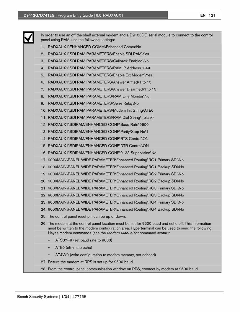
D9412G/D7412G | Program Entry Guide | 6.0 RADXAUX1 EN | 121
Bosch Security Systems | 1/04 | 47775E
In order to use an off-the-shelf external modem and a D9133DC serial module to connect to the controlpanel using RAM, use the following settings:
1. RADXAUX1\ENHANCED COMM\Enhanced Comm\No
2. RADXAUX1\SDI RAM PARAMETERS\Enable SDI RAM\Yes
3. RADXAUX1\SDI RAM PARAMETERS\Callback Enabled\No
4. RADXAUX1\SDI RAM PARAMETERS\RAM IP Address 1-4\0
5. RADXAUX1\SDI RAM PARAMETERS\Enable Ext Modem\Yes
6. RADXAUX1\SDI RAM PARAMETERS\Answer Armed\1 to 15
7. RADXAUX1\SDI RAM PARAMETERS\Answer Disarmed\1 to 15
8. RADXAUX1\SDI RAM PARAMETERS\RAM Line Monitor\No
9. RADXAUX1\SDI RAM PARAMETERS\Seize Relay\No
10. RADXAUX1\SDI RAM PARAMETERS\Modem Init String\ATE0
11. RADXAUX1\SDI RAM PARAMETERS\RAM Dial String\ (blank)
12. RADXAUX1\SDIRAM/ENHANCED CONF\Baud Rate\9600
13. RADXAUX1\SDIRAM/ENHANCED CONF\Parity/Stop No\1
14. RADXAUX1\SDIRAM/ENHANCED CONF\RTS Control\ON
15. RADXAUX1\SDIRAM/ENHANCED CONF\DTR Control\ON
16. RADXAUX1\SDIRAM/ENHANCED CONF\9133 Supervision\No
17. 9000MAIN\PANEL WIDE PARAMETER\Enhanced Routing\RG1 Primary SDI\No
18. 9000MAIN\PANEL WIDE PARAMETER\Enhanced Routing\RG1 Backup SDI\No
19. 9000MAIN\PANEL WIDE PARAMETER\Enhanced Routing\RG2 Primary SDI\No
20. 9000MAIN\PANEL WIDE PARAMETER\Enhanced Routing\RG2 Backup SDI\No
21. 9000MAIN\PANEL WIDE PARAMETER\Enhanced Routing\RG3 Primary SDI\No
22. 9000MAIN\PANEL WIDE PARAMETER\Enhanced Routing\RG3 Backup SDI\No
23. 9000MAIN\PANEL WIDE PARAMETER\Enhanced Routing\RG4 Primary SDI\No
24. 9000MAIN\PANEL WIDE PARAMETER\Enhanced Routing\RG4 Backup SDI\No
25. The control panel reset pin can be up or down.
26. The modem at the control panel location must be set for 9600 baud and echo off. This informationmust be written to the modem configuration area. Hyperterminal can be used to send the followingHayes modem commands (see the Modem Manual for command syntax):
• ATS37=9 (set baud rate to 9600)
• ATE0 (eliminate echo)
• AT&W0 (write configuration to modem memory, not echoed)
27. Ensure the modem at RPS is set up for 9600 baud.
28. From the control panel communication window on RPS, connect by modem at 9600 baud.

D9412G/D7412G | Program Entry Guide | 6.0 RADXAUX1 EN | 122
Bosch Security Systems | 1/04 | 47775E
Enable Ext Modem
Default: No
Selection: Yes or No
Yes Enable SDI Address 88 for use with anexternal modem.
No Disable SDI Address 88 for use with anexternal modem.
Setting this item to Yes instructs the control panelthat SDI Address 88 is enabled for use with anexternal modem. For further information on LocalRPS programming, see the RPS Operation Manual.
Setting this item to Yes disablesEnhanced Communication and SDI RAMfor use over a LAN or WAN.
Answer Armed
Default: 7
Selection: 0 to 15
0 No answer when all areas are MasterArmed.
0 to 15 The control panel answers the phoneafter the specified number of ringswhen all areas are Master Armed.
Determines the number of rings after which theexternal modem automatically answers a call if allareas are Master Armed.
Answer Disarmed
Default: 7
Selection: 0 to 15
0 No answer when any area is PerimeterArmed or Disarmed.
0 to 15 The control panel answers the phoneafter the specified number of ringswhen any area is Perimeter Armed orDisarmed.
Determines the number of rings after which theexternal modem automatically answers a call if anyarea is Perimeter Armed or Disarmed.
RAM Line Monitor
Default: No
Selection: Yes or No
This item is not yet implemented. Keep this item setto No.
Seize Relay
Default: No
Selection: Yes or No
This item is not yet implemented. Keep this item setto No.
Modem Init String
Default: ATE0
Selection: A to Z (capital letters only), 0 to 9,[SPACE], ! “ # $ % & ‘ ( ) * + , - . / : ;< = > ? @ [ \ ] ^ _
Determines which initialization string the controlpanel sends to the external modem when the controlpanel powers up.
010101010101
If special characters are required, thisitem can only be programmedsuccessfully from RPS. The D5200Programmer only allows the charactersshown in the Modem Init Stringdefault/selections.
RAM Dial String
Default: ATDT
Selection: Not available
This item is not yet implemented.
6.5 Enhanced CommunicationsEnhanced communications is the ability tocommunicate by some other means than thestandard digital dialer. In this section, programmableparameters allow you to define up to four separateenhanced communication paths to which events canbe routed. To route an event (such as an Alarm orTrouble) to an enhanced communication path,additional programming must also be completed inSection 2.3 Routing and Section 2.4 Enhanced Routing.

D9412G/D7412G | Program Entry Guide | 6.0 RADXAUX1 EN | 123
Bosch Security Systems | 1/04 | 47775E
Enhanced Comm
Default: No
Selection: Yes or No
Yes Enable enhanced communications overthe SDI bus.
No Do not enable enhancedcommunications over the SDI bus.
Determines if the control panel allows enhancedcommunications over the SDI bus.
010101010101
Modem Format must be set to Yes whenusing enhanced communications.
Enable Ext Modem must be set to No ifenhanced communications are to beused.
Enhanced Comm must be set to No if anexternal modem is to be used.
In order to completely disable EnhancedRouting over an SDI path, RG#PrimarySDI, RG#Backup SDI, and EnhancedComm prompts must all be set to No.
6.5.1 Programming Path Numbers and IPAddresses
There are up to four available paths to which eventscan be routed. If an event (or group of events) is tobe routed to an SDI path, the number entered inPrimary Device determines which SDI path is used(as long as RG# Prim, Primary SDI was set to Yesin Routing).
If events are to be routed to an IP address (in aprivate LAN/WAN application), determine whichpath is used (Path 1 to Path 4), and enter theappropriate IP Address for that path (see Path # IPAdd1 to Path # IP Add4).
If events are to be routed to an SDI Path but not toan IP Address, leave the Path # IP Add# set to 0.Path # Poll Rate, Path # Ack Wait, and Path #Retry Count must still be programmed.
Path # IP Add1
Default: 0
Selection: 0 to 255
0 to 255 Enter the first three digits of the IPaddress. If the first field is one or twodigits in length, leading zeros are notrequired.
This prompt and the next three determine the IPaddresses for each of the four paths available whenusing the D5200.
An IP address consists of four fields. Each field has arange of 0 to 255. For example, an IP address isexpressed as 110.227.64.190. The D5200programmer splits the IP address into fourprogrammable fields (see Figure 9). Be sure youcontact your network administrator to find outexactly where to send IP Address Events.
Figure 9: Path # IP Add1 to Add4
110.227.64.190
Path # IP Add1
Path # IP Add2
Path # IP Add3
Path # IP Add4
Path # IP Add2
Default: 0
Selection: 0 to 255
See Path 1 IP Add1.
Path # IP Add3
Default: 0
Selection: 0 to 255
See Path 1 IP Add1.
Path # IP Add4
Default: 0
Selection: 0 to 255
See Path 1 IP Add1.
Path # Poll Rate
Default: 0
Selection: 0, 5 to 65535 seconds
0 Disables the heartbeat poll (notrecommended, see the first ImportantNote that follows).
5 to 65535 Enables the poll rate for the amount oftime programmed here.

D9412G/D7412G | Program Entry Guide | 6.0 RADXAUX1 EN | 124
Bosch Security Systems | 1/04 | 47775E
This prompt and the next two prompts determinehow the SDI Path is supervised between the SDIdevice and the central station(s). Do not confuse withthe supervision of the SDI device (the connection ofthe SDI device to the 9000 series control panel).Each SDI Path can be configured to transmit aHeartbeat Event to the central station for supervisionpurposes. This ensures the integrity of theconnection at all times.
When sending reports to a central stationreceiver over a network path, thisprogramming prompt must be set to a non-zero value. Failure to program a value intothis field could prevent a failed networkcommunications path from restoring backto normal.
If the control panel is programmed to sendHeartbeat Events to the central station,consider the frequency. If the poll rate tothe central station is less than 60 seconds,the connection with RPS over a LAN orWAN becomes increasingly difficult thelower the poll rate is set.
The control panel readjusts the poll rate if itis less than 300 seconds to a temporarypoll rate of 300 seconds when online withRPS. The poll rate returns to theprogrammed value after the RPS session isover.
Each time the SDI Path sends this Heartbeat Event,it expects an acknowledgement within the amount oftime programmed in Path # Ack Wait. If theacknowledgement is not received, the control panelchecks to see if the Path # Retry Count entry isgreater than 0. If so, the control panel retries thenumber of times programmed (in Path # RetryCount) to send the Heartbeat Event before declaringthe Path as failed and generating a COMM FAILSDI ## (Path 1 = SDI 88, Path 2 = SDI 89, Path 3 =SDI 90, Path 4 = SDI 91) Event. If Poll Rate isprogrammed with a value and the central stationdoes not acknowledge the poll from the controlpanel, command centers do not annunciate a troublecondition. To transmit this event to the centralstation, see the Comm Fail prompt in Section 2.13.2Panel-Wide Relays.Example of Heartbeat:• Path # Poll Rate is set to 120 seconds• Path # Ack Wait time is set to 10 seconds• Path # Retry Count is set to 2When the control panel first powers up, the firstHeartbeat Event for Path 1 is sent and isacknowledged in 1 second. 120 seconds after thefirst Heartbeat Event is sent, the second HeartbeatEvent for Path 1 is generated and sent to the centralstation.Example of Retry Count:An acknowledgement of the heartbeat was notreceived in 10 seconds. The Heartbeat Event re-sends after the first 10 second ack wait periodexpires. If this Heartbeat Event is not acknowledged,the control panel declares this path as failed (andgenerates the Comm Fail ## Event). It continues tore-send the Heartbeat Event every 10 seconds untilit is acknowledged.
Figure 10: Poll Rate Timeline
10 20 30 40 50 60 70 80 90 100 110 120 130 140 150 160 170 180 190 200 210
2
3
1
8
4
5
6
7
9
1 - Control panel powered up2 - Acknowledgement received3 - Heartbeat Event sent4 - Second Heartbeat Event sent5 - No acknowledgement, Heartbeat re-sent, retry #1
6 - No acknowledgement, Heartbeat re-sent, retry #27 - Path declared as failed8 - 10-second interval9 - Additional Heartbeats sent every 10 seconds until
acknowledged

D9412G/D7412G | Program Entry Guide | 6.0 RADXAUX1 EN | 125
Bosch Security Systems | 1/04 | 47775E
Once the control panel receives acknowledgementfrom the central station, the control panel returns tothe normal Poll Rate (which, in this example is 120seconds).
If more than one SDI Path is used, the control panelhandles them on a successive basis. For example, ifacknowledgement from SDI Path 1 is not receivedwithin 10 seconds (using the previous example), thecontrol panel moves to SDI Path 2 to send itsHeartbeat Event (and subsequently waits for the ack)before returning to SDI Path 1 to re-send itsheartbeat.
Beginning with firmware revision 6.20, ifHeartbeats are enabled and primary is anSDI (or IP address) and the primary pathfails due to a heartbeat failure, then allevents should immediately go to thebackup path.
Entries are made in 1-second increments.
010101010101
Even though RPS and the D5200 allowentries of 1 to 4, the control panelinterprets these entries as an entry of 5.
010101010101
5 minutes = 300 seconds1 hour = 3600 seconds12 hours = 43,200 seconds18 hours = 64,800 seconds
Path # Ack Wait
Default: 13
Selection: 0, 5 seconds to 65535 seconds
0 The control panel does not look forany acknowledgement from the centralstation.
5 to 65535 The control panel waits this amount oftime to receive an acknowledgementfrom the central station.
Determines how long the control panel waits for anacknowledgement from the central station after aHeartbeat Event (poll) or an actual event wastransmitted. This prompt is only applicable to SDItransmitted events. Entries are made in 1-secondincrements.
010101010101
Even though RPS and the D5200 allowentries of 1 to 4, the control panelinterprets these entries as an entry of 5.
The value entered for Path # Ack WaitTone must not equal the time out entrymade in the RPS Account (see the RPSOperation Manual, v2.9 or higher). Instead,offset these values by 2 or 3. For example,if your Path # Ack Wait time = 15,program your Time Out value as 17 in theRPS account.
Path # Retry Count
Default: 5
Selection: 0 to 255
0 COMM FAIL RG# SDI ### Eventsare not generated.
1 to 255 COMM FAIL RG# SDI ### Eventsare generated after the number ofretries are reached for a given SDIpath.
Determines how many times the control panelresends the Heartbeat Event before declaring a pathfailure and generating a COMM FAIL RG# SDI### (RG # = 1 to 4, SDI ### = 88 for Path 1, 89for Path 2, 90 for Path 3, 91 for Path 4) Event.
6.6 SDI RAM/EnhancedCommunications Configuration
This section provides the necessary prompts neededfor configuring the D9133TTL-E SDI-EthernetInterface Module when using it for SDI RAMand/or SDI enhanced communication applications.
Baud Rate
Default: 9600
Selection: 300, 1200, 2400, 4800, 9600, 14.4 K
This item determines the communication baud ratefor the D9133TTL-E. Because the SDI buscommunicates at 9600 baud, keep this prompt alsoat 9600 baud. Pressing the [SPACE] bar on theD5200 toggles through the available options.
Do not change this value to any othersetting than 9600 baud.

D9412G/D7412G | Program Entry Guide | 6.0 RADXAUX1 EN | 126
Bosch Security Systems | 1/04 | 47775E
Parity/Stop
Default: No/1
Selection: No/1, No/2, Odd/1, Even/1
No/1 No parity, 1 stop bit.
No/2 No parity, 2 stop bits.
Odd/1 Odd parity, 1 stop bit.
Even/1 Even parity, 1 stop bit.
This prompt addresses two items: Parity and thenumber of stop bits for the D9133TTL-E. Pressingthe [SPACE] bar on the D5200 toggles through theavailable options.
This item must be set to No/1 when usingthe External Modem feature.
RTS Control
Default: On
Selection: On, AutoX, Off, AutoR
On Sets RTS to on (hardware control).
Auto X Automatically enables Xon/Xoff(software control).
Off Sets RTS off (hardware control).
Auto R Sets this to Auto RTS.
Determines how the Request To Send Controlparameters are defined for the D9133TTL-E.Pressing the [SPACE] bar on the D5200 togglesthrough the available options.
This item must be set to On when usingthe External Modem feature.
DTR Control
Default: On
Selection: On, AutoD, Off
On Sets DTR to on (hardware control).
AutoD Sets this to Auto DTR.
Off Sets DTR off (hardware control).
Determines how the Data Terminal Ready Controlparameters are defined for the D9133TTL-E.Pressing the [SPACE] bar on the D5200 togglesthrough the available options.
This item must be set to On when usingthe External Modem feature.
9133 Supervision
Default: No
Selection: Yes or No
Yes Supervise the D9133TTL-E NetworkInterface Module.
No Do not supervise the D9133TTL-ENetwork Interface Module.
This item determines whether the D9133TTL-E issupervised or not. If the D9133TTL-E is supervised,disconnecting it from the control panel creates aTrouble SDI 88 Event and the commandcenterannunciates a trouble tone and displaysSERVC SDI 88.
Trouble SDI 88 Reports are alwaysreported using Area 1’s account number.
Base Port Number
Default: 7700
Selection: 0 to 65535
The base port number is the port number of theCoBox , such as 7700. This is used in the futurerevision and is not needed at this time.
6.6.1 Route Group Attempts
This section determines how many times a routegroup tries the primary destination beforeattempting the backup destination should theprimary destination fail. This entry applies to bothPhone numbers and IP addresses.

D9412G/D7412G | Program Entry Guide | 6.0 RADXAUX1 EN | 127
Bosch Security Systems | 1/04 | 47775E
RG# 1 Attempt
Default: No
Selection: Yes or No
Yes This route group attempts the primarydestination once and, if unsuccessful,attempts the backup destination. Thecontrol panel still makes a total of tenattempts (five to the primary, five tothe backup) before generating a routegroup Comm Fail Event.
No This route group attempts the primarydestination twice and, if unsuccessful,attempts the backup destination. Thecontrol panel still makes a total of tenattempts (six to the primary, four to thebackup) before generating a routegroup Comm Fail Event.
6.7 Miscellaneous
Fire Supv Res Type
Default: 0
Selection: 0, 1, 2
0 The control panel transmits a FIRETROUBLE RESTORE when a FireSupervision point restores to normal.
1 The control panel transmits a FIREALARM RESTORE when a FireSupervision point restores to normal.
2 The control panel transmits a FIRESUPERVISION RESTORE when aFire Supervision point restores tonormal.
Determines how the control panels transmits a FireSupervision Restoral Event.
010101010101
Beginning with version 6.20, the Fire SupvRestore Event was added to Fire Events inRouting. It is not necessary to set this itemto 2 any longer. If Fire Supervision RestoreEvents are needed, simply enable them inRouting.
Enable Protocol Type
Default: No
Selection: Yes or No
Not required at this time. Leave at default value.
Enable Anti Replay
Default: No
Selection: Yes or No
This feature is used primarily for two purposes:
Anti-Replay: A strategy designed against replayattacks. This feature prevents substitution of acontrol panel/network interface module (NIM)solution for delivering events over a network.
A replay attack occurs when a hacker records amessage sent over the network by Device A andreplaces this message at a later time whilepretending to be Device A.
If this function is required, you must alsoenable the Anti-Replay function in theD6600 Receiver. See the D6600Operation and Installation Manual(P/N: 39964) for further details.
Account Identification: With version 6.0, theD6600 Receiver identified NetCom accounts by theIP address received in the message sent from thecontrol panel. With version 6.2, the D6600 Receivercan identify the NetCom accounts by either the IPaddress and/or the account number received in themessage sent from the control panel. The accountnumber transmitted in the message is always Area1’s account number. Although up to ten digits canbe programmed for the account number, only eightdigits are sent in the message to the D6600 receiver.
Fire Trouble Resound
Default: 0
Selection: 0, 1, 2
0 Command centers do not re-sound thefire trouble tone.
1 Command centers re-sound the firetrouble tone at 12:00 PM if any Firepoint that falls within the scope of acommand center is in an off-normalcondition.
2 Command centers re-sound the firetrouble tone at 12:00 AM if any Firepoint that falls within the scope of acommand center is in an off-normalcondition.

D9412G/D7412G | Program Entry Guide | 6.0 RADXAUX1 EN | 128
Bosch Security Systems | 1/04 | 47775E
This item determines if a fire trouble condition,previously acknowledged and silenced at acommand center, automatically (locally) resoundsthe fire trouble tone at 12:00 PM, 12:00 AM, or notat all if the point is still in an off-normal state. Eventsare not generated at the time resound occurs.
6.8 Cross Point ParametersThis section discusses the requirements necessary toprogram Cross Point functions.
If a 9000 Series Control Panel is upgradedto version 6.30, you MUST useRADXAUX1 Handler version 1.05 orhigher. Failure to do so may causeunexpected point response behavior (seeSection 6.2 RPS and D5200 HandlerRequirements.)
The Cross Point option is designed to reduce falsealarms. To achieve this, points can be programmedsuch that the control panel needs to see an Alarmcondition within a programmed period of time(called Cross Point Time) from at least two pointswithin a Cross Point Group (see Table 40) beforeCross Point Alarm Events are generated. Thesepoints need the Cross Point option enabled in theircorresponding point indexes to be able to generatethis event.
Cross Point Groups were established in the D9412Gand D7412G to support the Cross Point functions.There are 31 Cross Point Groups in the D9412Gand ten in the D7412G. Each Cross Point Groupconsists of eight points and is identified by the pointnumbers in them (for example, Cross Points 1 to 8,Cross Points 9 to 16, and so on). The maximumnumber of points that can be programmed to meetthe Cross Point criteria is two. Point numbers fromdifferent Cross Point Groups do not affect eachother. See Table 40 for a complete listing of CrossPoints comprising each Cross Point Group.
Table 40: Cross Point Ranges Within Groups
Cross Point Group Point Range1 1 to 82 9 to 163 17 to 244 25 to 325 33 to 406 41 to 487 49 to 568 57 to 649 65 to 7210 73 to 8011 81 to 8812 89 to 9613 97 to 10414 105 to 11215 113 to 12016 121 to 12717 129 to 13618 137 to 14419 145 to 15220 153 to 16021 161 to 16822 169 to 17623 177 to 18424 185 to 19225 193 to 20026 201 to 20827 209 to 21628 217 to 22429 225 to 23230 233 to 24031 241 to 247
When any Cross Point detects an alarm condition,the control panel starts a timer as programmed inthe Cross Point Time prompt.
If a second Cross Point within the same Cross PointGroup detects an alarm condition, the control panelcreates a Cross Point Alarm Event for both points,provided both points activate inside the Cross PointWindow.
If a single Cross Point detects an alarm and staysfaulted throughout the Cross Point Window, astandard Alarm Report is generated for that point.

D9412G/D7412G | Program Entry Guide | 6.0 RADXAUX1 EN | 129
Bosch Security Systems | 1/04 | 47775E
Conversely, if a single Cross Point detects an alarm,then restores, and no other conditions occur, anUnverified Event is generated for that point. Asecond alarm on the first point does not create anAlarm Event but rather an Unverified Event.
Section 2.3 Routing determines whether these eventsare transmitted to a central station. An UnverifiedEvent does not produce a corresponding RestoralEvent.
The Cross Point function applies only to alarmconditions. It does not apply to supervisory ortrouble conditions. Points programmed with pointresponse D (Delayed) eventually go into an alarmcondition if the area is not disarmed in time.
Use the Cross Point function on Non-firepoints only.
Cross Point Time
Default: 20 seconds
Selection: 5 seconds to 255 seconds
Select the amount of time (in seconds) that pointswithin a Cross Point Group are in alarm before aCross Point event is generated.

D9412G/D7412G | Program Entry Guide | 6.0 RADXAUX1 EN | 130
Bosch Security Systems | 1/04 | 47775E
Notes

D9412G/D7412G | Program Entry Guide | 7.0 RADXAXS EN | 131
Bosch Security Systems | 1/04 | 47775E
7.0 RADXAXS 7.1 Door ProfileThis programming category is used to:
• Assign an area, that also activates the D9210B
• Assign a point to the door
• Program the door state to change when the armstate changes
• Allow for the Strike relay to activate upon a firealarm
Door #
Default: 20 seconds
Selection: 1 seconds to 8 seconds
Enter the number of the door you are about toprogram.
The D9412G supports up to eight doors.The D7412G supports two doors.
D# Entry Area #
Default: Blank
Selection: Blank, 1 to 8
1 to 8 The area assigned to the doorcontroller to which the reader allowsaccess.
Blank Door controller does not function.
Assign an area to the door controller. This entryallows the D9210B to be polled, activatingcommunication to the control panel. This also is thearea a user exits when initiating a REX.
All SDI devices, regardless of areaassigned, report to Area 1, Account 1 bydefault upon SDI failure. If a D9210Bbecomes disconnected, an SDI Fail ##and a Missing Point ### Event is created.
010101010101
9210 NOT READY appears at thiscommand center when you press the[ENTER] key if the D9210B is notprogrammed with a D# Entry Area.
D#CC#Scope
Default: Blank
Selection: Blank, 1 to 8
1 to 8 Determines disarming rights. Theuser’s access level in conjunction withthe CC # Scope determines whichareas are disarmed.
Blank Only the area assigned to the D#Entry Area disarms this door.
Enter the command center number (CC#) whichdetermines the scope of the user ID’s disarmingrights. Areas disarm on the basis of this commandcenter’s scope and the authority level of the user.
D# Door Point
Default: Blank
Selection: Blank, 1 to 127, 129 to 247
1 to 127,129 to 247
The point number assigned to thisdoor. Points 128 and 248 are reservedby the control panel for internal use.
Blank There is no point number assigned tothis door.
Enter the point number assigned to this door. Thispoint cannot be used for any other pointassignments.
Door points must be programmed asPerimeter points. If a 24-hour point type isrequired for the Door point, you may use aPerimeter point type with a point responseof 9 to C. Also, the debounce count mustbe set to 4 in Point Assignments.
010101010101
When assigning Points 1 to 8 (controlpanel zones), the end-of-line (EOL)resistors must be removed from the controlpanel. In addition to this, do not enable anyPOPIT points (or OctoPOPIT points)sharing the same point number as theDoor point. Failure to do so results in extrapoint trouble conditions upon reboot.

D9412G/D7412G | Program Entry Guide | 7.0 RADXAXS EN | 132
Bosch Security Systems | 1/04 | 47775E
D# Interlock Point
Default: Blank
Selection: Blank, 1 to 127, 129 to 247
1 to 127,129 to 247
The point number assigned to theInterlock point. Points 128 and 248 arereserved by the control panel forinternal use.
Blank There is no point number assigned tothe Interlock point.
Enter the Interlock point number. This point, whenfaulted, prevents the door controller from allowingaccess upon a valid ID read or door request.
Do not assign this point to another Door point. Youmay assign it to another controller. One Interlockpoint prevents multiple controllers from activating.
Door points must be programmed asPerimeter points. If a 24-hour point type isrequired for the Door point, you can use aPerimeter point type with a PointResponse of 9 to C. Also, the debouncecount must be set to 4 in PointAssignments.
The Interlock point is considered in anormal state if it is bypassed, swingerbypassed, or forced armed. This results innormal access even if the door is left open.
D# Auto Door?
Default: No
Selection: Yes or No
Yes When the area assigned in D# EntryArea # is disarmed, the door is in theunlocked state. When that area isarmed, the door returns to the lockedstate.
No Door state is not affected by the armedstate of the area.
Use this program item to automatically unlock thedoor (latched, shunt, and strike) when the entry areais disarmed. The door re-locks upon Master orPerimeter Arming the area.
The unlocked state cannot be overriddenmanually.
Doors that are activated by Fire Unlockmust be returned to normal using the DoorControl function on the control center.
D# Fire Unlock?
Default: No
Selection: Yes or No
Yes Relay activates and shunt is applied forthe door contact automatically upon aFire Alarm.
No Door remains in its current mode upona Fire Alarm.
Use this program item to activate the relay for thedoor strike and shunt the door zone automaticallyupon a Fire Alarm. This feature overrides a SecureDoor state, Locked Door state, Auto Door, and anInterlock Faulted point. The relay activates for alldoors with this prompt programmed Yes when aFire Alarm occurs in any area. Relays that areactivated by Fire Unlock can only be returned tonormal through the command center using the DoorControl function.
This unlocks the door regardless of thearmed state.
Each fire alarm that is generated causes aDoor Unlocked – Automatic Event.
D# Disarm on Open?
Default: Yes
Selection: Yes or No
Yes The area disarms only after the doorwas opened for a user with a validdisarm level.
No The area disarms whether or not thedoor was opened as soon as a user witha valid disarm level presents a validtoken/card.
Use this program item to determine whether thedoor needs to be physically opened prior todisarming the area upon a valid access request. Theuser initiating the access request needs access levelsthat allow disarming with ID.
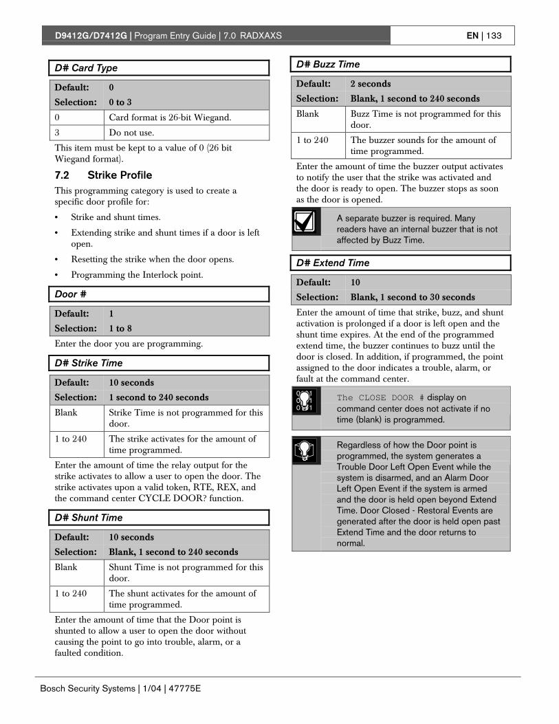
D9412G/D7412G | Program Entry Guide | 7.0 RADXAXS EN | 133
Bosch Security Systems | 1/04 | 47775E
D# Card Type
Default: 0
Selection: 0 to 3
0 Card format is 26-bit Wiegand.
3 Do not use.
This item must be kept to a value of 0 (26 bitWiegand format).
7.2 Strike ProfileThis programming category is used to create aspecific door profile for:
• Strike and shunt times.
• Extending strike and shunt times if a door is leftopen.
• Resetting the strike when the door opens.
• Programming the Interlock point.
Door #
Default: 1
Selection: 1 to 8
Enter the door you are programming.
D# Strike Time
Default: 10 seconds
Selection: 1 second to 240 seconds
Blank Strike Time is not programmed for thisdoor.
1 to 240 The strike activates for the amount oftime programmed.
Enter the amount of time the relay output for thestrike activates to allow a user to open the door. Thestrike activates upon a valid token, RTE, REX, andthe command center CYCLE DOOR? function.
D# Shunt Time
Default: 10 seconds
Selection: Blank, 1 second to 240 seconds
Blank Shunt Time is not programmed for thisdoor.
1 to 240 The shunt activates for the amount oftime programmed.
Enter the amount of time that the Door point isshunted to allow a user to open the door withoutcausing the point to go into trouble, alarm, or afaulted condition.
D# Buzz Time
Default: 2 seconds
Selection: Blank, 1 second to 240 seconds
Blank Buzz Time is not programmed for thisdoor.
1 to 240 The buzzer sounds for the amount oftime programmed.
Enter the amount of time the buzzer output activatesto notify the user that the strike was activated andthe door is ready to open. The buzzer stops as soonas the door is opened.
A separate buzzer is required. Manyreaders have an internal buzzer that is notaffected by Buzz Time.
D# Extend Time
Default: 10
Selection: Blank, 1 second to 30 seconds
Enter the amount of time that strike, buzz, and shuntactivation is prolonged if a door is left open and theshunt time expires. At the end of the programmedextend time, the buzzer continues to buzz until thedoor is closed. In addition, if programmed, the pointassigned to the door indicates a trouble, alarm, orfault at the command center.
010101010101
The CLOSE DOOR # display oncommand center does not activate if notime (blank) is programmed.
Regardless of how the Door point isprogrammed, the system generates aTrouble Door Left Open Event while thesystem is disarmed, and an Alarm DoorLeft Open Event if the system is armedand the door is held open beyond ExtendTime. Door Closed - Restoral Events aregenerated after the door is held open pastExtend Time and the door returns tonormal.

D9412G/D7412G | Program Entry Guide | 7.0 RADXAXS EN | 134
Bosch Security Systems | 1/04 | 47775E
D# Deact On Open?
Default: Yes
Selection: Yes or No
Yes Strike deactivates when the door isopened after a valid Access Grantedrequest.
No Strike remains activated for the amountof the programmed strike time whetherdoor is opened or closed.
Determines if the strike deactivates immediatelyupon physically opening the door.
010101010101 In order for this function to work, a point
needs to be assigned to the door.
To Reduce False Alarms, maintain D#Deact on Open? as the default (Yes). Thishelps prevent the door from bouncingopen and causing a false alarm.
D# RTE Shunt Only?
Default: No
Selection: Yes or No
Yes Programmed shunt time activates sodoor can be manually opened.
No RTE automatically activates theprogrammed strike and shunt time.
Use this program item to disable the strike, but stillactivate the programmed shunt time upon a Requestto Exit (REX) area.
Use this parameter when a user can opena door manually without relying on atoken/card to activate the strike (such aswith a push bar).
When RTEShunt Only is Yes, RTE Eventsare not logged, reported, or printed.
D# REXShunt Only?
Default: No
Selection: Yes or No
Yes Programmed shunt time activates sothe door can be manually opened.
No REX automatically activates theprogrammed strike and shunt time.
Use this program item to disable the strike, but stillactivate the programmed shunt time upon a REX anarea.
Use this parameter when a user can opena door manually without relying on atoken/card to activate the strike (such aswith a push bar).
When REXShunt Only is Yes, REXEvents are not logged, reported, orprinted.
7.3 Event ProfileThis programming category is used to determine ifevents are created for:
• Access Granted and Access Denied
• Door Requests
• Door state changes due to manual (commandcenter) or automatic scheduled or armed statechanges (skeds/hold open on disarm, normal onarmed) operation.
Door #
Default: 1
Selection: 1 to 8
Enter the door you are about to program.
010101010101 RTE Events require Access Granted to be
programmed Yes.

D9412G/D7412G | Program Entry Guide | 7.0 RADXAXS EN | 135
Bosch Security Systems | 1/04 | 47775E
D# Access Granted?
Default: No
Selection: Yes or No
Yes Access Events from this door controllerare sent to the control panel forprocessing.
No Access Events from this door controllerare not sent to the control panel forprocessing.
This program item determines if Access Grantedand Door Request Events are sent to the controlpanel for processing memory, printing, and remotereporting.
010101010101
A successful Access Event can beinitiated by a(n):
• Valid user ID
• Valid door state changed at thecommand center.
• Automatically scheduled or armedstate change that holds a door open
• RTE/exit (RTE/REX).
D# No Entry?
Default: No
Selection: Yes or No
Yes Access Denied Events from this doorcontroller are sent to the control panelfor processing.
No Access Denied Events from this doorcontroller are not sent to the controlpanel for processing.
This program item determines if No Entry Eventsare sent to the control panel for processing memory,printing, and remote reporting.
010101010101
A No Entry Event can be caused by:
• Invalid or unknown user ID, interlock orsecured door, or incorrect authoritylevel
• RTE/REX for door in interlock orsecured door.
D# Enter Request?
Default: No
Selection: Yes or No
Yes A Door RTE Event from this doorcontroller is sent to the control panelfor processing.
No A Door RTE Event from this doorcontroller is not sent to the controlpanel for processing.
This program item determines if RTE Events aresent to the control panel for processing memory,printing, and remote reporting.
010101010101 RTE Events require D# Access Granted
to be programmed Yes.
D# Exit Request?
Default: No
Selection: Yes or No
Yes A Door RTE Event from this doorcontroller is sent to the control panelfor processing.
No A Door RTE Event from this doorcontroller is not sent to the controlpanel for processing.
This program item determines if REX Events aresent to the control panel for processing memory,printing, and remote reporting.
010101010101 REX Events require D# Access Granted
to be programmed Yes.

D9412G/D7412G | Program Entry Guide | Programming Prompts Directory EN | 136
Bosch Security Systems | 1/04 | 47775E
Programming PromptsDirectory9000MAIN .............................................................11
Phone...............................................................11
Phone 1.....................................................11
Phone 2.....................................................11
Phone 3.....................................................11
Phone 4.....................................................11
Phone Parameters ........................................12
Modem Format........................................12
Point/User Flag........................................12
DTMF Dialing .........................................13
Phone Supv Time ....................................14
Alarm On Fail..........................................14
Buzz on Fail..............................................14
Two Phone Lines.....................................14
BFSK Duress Code..................................15
Expand Test Rpt......................................15
Ground Start ............................................15
Routing ...........................................................15
Dialing Attempts ............................................16
Route #.....................................................17
R# Primary Device .................................17
R# Backup Device ..................................17
View Events?............................................17
Fire Reports.......................................18
Burglar Reports.................................18
User Reports .....................................19
Test Reports ......................................14
Diag Reports .....................................20
Relay Reports ...................................21
AutoFunc Reports ............................21
RAM Reports....................................22
Point Reports ....................................22
User Chng Reports...........................23
Access Reports..................................23
Enhanced Routing........................................23
Programming a Duplicate Report ..................16
RG# Primary SDI ...................................24
RG# Backup SDI ....................................24
RG# Primary Pager.................................25
Power Supervision .......................................27
AC Fail Time ...........................................27
AC Fail/Res Rpt ......................................28
AC Tag Along..........................................28
AC/Battery Buzz......................................29
Bat Fail/Res Rpt ......................................29
Printer Parameters .......................................29
Printer Address ........................................29
P### Area Assign...................................92
P## Supervised .......................................29
P## Scope ................................................30
P## A1 [through A8] in Scope.......30
P## Fire Events.......................................30
P## Burglar Event ..................................30
P## Access Event....................................30
P## User Event .......................................30
P## Test Event........................................30
P## Diag Event .......................................30
P## Auto Functions Event.....................31
P## RAM Event .....................................31
P## Relay Event .....................................31
P## Point Event ......................................31
P## Usr Chng Evt ..................................31
RAM Parameters ..........................................31
RAM Callback Reports ...................................31
RAM Passcode.........................................32
Log % Full ................................................32
RAM Call Back........................................32
RAM Line Monitor .................................32
Answer Armed.........................................33
Answer Disarmed ....................................33
Ram Ph .....................................................33
Miscellaneous ..............................................127
Duress Type .............................................34
Cancel Report ..........................................34

D9412G/D7412G | Program Entry Guide | Programming Prompts Directory EN | 137
Bosch Security Systems | 1/04 | 47775E
Area Parameters...........................................34
Area Parameters .............................................34
Area...........................................................34
A# Area On .............................................34
Error! Reference source not found.Error!Bookmark not defined.
A# FA Bypass Max.................................36
A# Delay Res...........................................36
A# Exit Tone ...........................................36
A# Exit Dly Time ...................................36
A# Auto Watch .......................................37
A# Verify Time .......................................37
A# Duress Enable ...................................38
A# Area Type..........................................39
Bell Parameters ..............................................40
Area...........................................................40
A# Fire Time ...........................................41
A# Fire Pat ...............................................41
A# Burg Time..........................................41
A# Burg Pat .............................................41
A# Single Ring ........................................41
A# Bell Test .............................................42
Open/Close Options ........................................42
Area...........................................................43
A# Acct O/C ...........................................43
A# Area O/C...........................................44
A# Disable O/C in Window..................44
A# Auto Close.........................................44
A# Fail to Open ......................................44
A# Fail to Close.......................................45
A# Restrictd O/C....................................45
A# Perimeter O/C ..................................46
Command Center.........................................46
Cmd Cntr (Command Center) Assignment .....46
Cmd Center .............................................46
CC# Supervised ......................................47
CC# Area Assign ....................................47
CC# Scope...............................................47
CC# A1[through A8] in Scope.......48
CC# Entr Key Rly ..................................48
CC# Entr Cycl Dr...................................48
CC# Assign Door....................................49
CC# Trouble Tone .................................49
CC# Entry Tone......................................49
CC# Exit Tone ........................................49
CC# Arm Now Warn .............................50
CC# Close Door .....................................50
CC# EnhancCmdCtr..............................50
Area Text .......................................................50
Area...........................................................50
Area# Is On .............................................50
Area # Not Ready ...................................50
Area # Is Off ............................................50
Area # Acct Is On...................................51
Custom Function ............................................51
Custom Function .....................................51
CF### Text.............................................51
CF### Key Strokes ................................52
User Interface................................................53
Command Center Selections............................53
Master Arm Delay...................................54
Mstr Arm Inst ..........................................54
Perim Instant ............................................54
Perim Delay..............................................54
Watch Mode.............................................54
Perim Partial.............................................54
View Area Stat .........................................55
View Memory..........................................55
View Pt Status ..........................................55
Walk Test..................................................55
Fire Test ....................................................55
Send Report .............................................55
Door Control............................................55
Access Ctl Level ......................................56
Chg Display..............................................56
Chg Time/Date........................................56
Chg Passcode ...........................................56
Add User ..................................................56
Del User....................................................56
Extend Close ............................................56
View Log ..................................................56
Print Log ...................................................57

D9412G/D7412G | Program Entry Guide | Programming Prompts Directory EN | 138
Bosch Security Systems | 1/04 | 47775E
User Cmd 7..............................................57
User Cmd 9..............................................57
Bypass a Pt ...............................................57
Unbypass a Pt ..........................................57
Reset Sensors ...........................................57
Change Relay...........................................57
Remote Program......................................57
Move to Area ...........................................58
Display Rev..............................................58
Service Walk ............................................58
Default Text .............................................58
Change Skeds...........................................58
C Function 128 [through 143]................58
Authority Level Selections ...............................59
Authority Level........................................59
L## Disarm .............................................59
L## Master Arm Delay..........................59
L## Mstr Arm Inst .................................59
L## Perim Instant...................................60
L## Perim Delay ....................................60
L## Watch Mode ...................................60
L## Perim Partial....................................60
L## View Area Stat................................60
L## View Memory.................................60
L## View Pt Status .................................60
L## Walk Test ........................................60
L## Fire Test ...........................................61
L## Send Report ....................................61
L## Door Control...................................61
L## Cycle Door...............................61
L## Unlock Door ............................62
L## Secure Door ..........................62
L## Access Ctl Lvl .................................62
L## Chg Display.....................................63
L## Chg Time/Date...............................63
L## Chg Passcode ..................................63
L## Add User .........................................63
L## Del User...........................................63
L## Extend Close...................................63
L## View Log .........................................63
L## Print Log..........................................63
L## User Cmd 7.....................................63
L## User Cmd 9.....................................64
L## Bypass a Pt.......................................64
L## Unbypass a Pt .................................64
L## Reset Sensors...................................64
L## Change Relay..................................64
L## Remote Program.............................64
L## Move to Area ..................................64
L## Display Rev.....................................64
L## Service Walk ...................................64
L## Default Text ....................................65
L## Change Skeds..................................65
L## C Function 128 [through 143].......65
L## Force Arm .......................................65
L## Area O/C.........................................65
L## Restricted O/C................................65
L## Perimeter O/C ................................65
L## Send Duress.....................................65
L## Passcode Arm..................................65
L## Passcode Disarm.............................66
L## Security Level..................................66
L## Disarm Level...................................66
Function List ..................................................67
Menu Item................................................67
M## Function..........................................67
M## CC Address 1 [through 8] ............67
Relay Parameters .........................................67
Area Relays ....................................................68
Area...........................................................68
A# Alarm Bell..........................................68
A# Fire Bell..............................................69
A# Reset Sensors.....................................69
A# Fail to Close.......................................69
A# Force Armed .....................................69
A# Watch Mode......................................69
A# Area Armed.......................................70
A# Area Fault ..........................................70
A# Duress Relay .....................................70
A# Perim Fault ........................................70
A# Silent Alarm.......................................70

D9412G/D7412G | Program Entry Guide | Programming Prompts Directory EN | 139
Bosch Security Systems | 1/04 | 47775E
Panel-Wide Relays .........................................71
AC Failure ................................................71
Battery Trouble........................................71
Phone Fail.................................................71
Comm Fail................................................72
Log % Full ................................................72
Summary Fire ..........................................72
Summary Alarm ......................................72
Summary Fire Tbl ...................................72
Summary SupFire....................................72
Summary Trouble ...................................72
Summary SupBurg ..................................72
RADXUSR1/RADXUSR2 ..................................73
Passcode/Token Worksheet.......................73
Reporting and Logging....................................73
User ###..................................................74
U### Passcode .......................................74
U### User Group ..................................75
U### Area 1 [through Area 8] Auth....75
U### Name ............................................75
U### Mstr Site .......................................75
U### Mstr C/D......................................76
U### SU1 through SU3 Site ................76
U### SU1 through SU3 C/D...............76
RADXPNTS ..........................................................77
Point Index.....................................................77
Point Index...............................................77
P## Type .................................................77
Point Responses ..............................................81
P## Pt Response .....................................82
P## Entry Delay .....................................83
P## Ent Tone Off ...................................83
P## Silent Bell.........................................83
P## Ring Til Rst .....................................83
P## Audible After 2 Failures.................84
P## Invisible Pt.......................................84
P## Buzz On Fault .................................85
P## Watch Point.....................................85
P## RlyResp Type .................................86
P## Disp as Dvc .....................................86
P## Local While Disarmed ...................86
P## Local While Armed........................86
P## Disable Rst.......................................87
P## FA Retrnable ...................................87
P## BP Retrnable ...................................87
P## Bypassable .......................................88
P## Swinger Byps...................................88
P## Report Bypass at Occurrence........88
P## Defer BP Report .............................89
P## Cross Point ......................................89
P## Fire Point .........................................90
P## Alarm Verify ...................................91
P## Resettable.........................................91
Point Assignments ........................................91
Point Number...........................................91
P### Point Index ...................................92
P### Area Assign...................................92
P### Debounce ......................................92
P### BFSK/Relay ..................................93
P### Point Text......................................93
COMMAND 7 and COMMAND 9 ...........94
CMD7 Point Index..................................94
CMD7 BFSK/Relay ................................94
CMD7 Point Text....................................94
CMD9 Point Index..................................94
CMD9 BFSK/Relay ................................94
CMD9 Point Text....................................94
RADXSKED..........................................................95
Windows .........................................................95
Opening and Closing ......................................95
Window ....................................................95
W# Sunday ..............................................95
W# Monday.............................................96
W# Tuesday.............................................96
W# Wednesday .......................................96
W# Thursday...........................................96
W# Friday ................................................96
W# Saturday ............................................96
W# Open Early Begin ............................96
W# Open Window Start ........................96
W# Open Window Stop.........................97
W# Close Early Begin ............................98

D9412G/D7412G | Program Entry Guide | Programming Prompts Directory EN | 140
Bosch Security Systems | 1/04 | 47775E
W# Close Window Start ........................99
W# Close Window Stop.........................99
W# Xept Holiday..................................100
W# Holiday 1 ........................................100
W# Holiday 2 ........................................100
W# Holiday 3 ........................................100
W# Holiday 4 ........................................100
W# Area 1 [through 8] .........................100
User Group Windows...................................102
User Windows #....................................102
UW# User Group .................................102
UW# Sunday .........................................103
UW# Monday .......................................103
UW# Tuesday .......................................103
UW# Wednesday..................................103
UW# Thursday......................................103
UW# Friday...........................................103
UW# Saturday.......................................103
UW# Group Enable..............................103
UW# Group Disable.............................103
UW# Xept Holiday ..............................104
UW# Holiday 1.....................................104
UW# Holiday 2.....................................104
UW# Holiday 3.....................................104
UW# Holiday 4.....................................104
Skeds .............................................................104
Sked Number .........................................104
S## TimeEdit ........................................104
S## Function Code...............................105
S## Area 1[through 8] ..................105
S## Area 1[through 8] ..................105
S## Point Number.........................105
S## Point Number.........................105
S## Area 1[through 8] ..................106
S## Relay Number........................106
S## Relay Number........................106
S## Defer Test ...............................107
S## Hourly Report........................107
S## Defer Status ............................107
S## Cmd Center............................108
S## Custom Func ..........................108
S## Cmd Center 1[through 8] .....109
S## Access Ctl Level #.................109
S## Access Ctl Level#..................109
S## Door 1 [through 8].................109
S## Door 1 [through 8].................110
S## Door 1 [through 8].................110
S## Door 1 [through 8].................110
S## Door 1 [through 8].................111
S## Door 1 [through 8].................110
S## Door 1 [through 8].................111
S## Time ...............................................112
S## Date ................................................112
S## Sunday............................................112
S## Monday ..........................................112
S## Tuesday ..........................................112
S## Wednesday ....................................112
S## Thursday ........................................112
S## Friday .............................................112
S## Saturday .........................................112
S## Xept Holiday.................................113
S## Holiday 1 .......................................113
S## Holiday 2 .......................................113
S## Holiday 3 .......................................113
S## Holiday 4 .......................................113
Holiday Indexes..........................................113
Add/Change/Delete.......................................113
Date .........................................................113
Holiday Index 1.....................................114
Holiday Index 2.....................................114
Holiday Index 3.....................................114
Holiday Index 4.....................................114
View Holidays ..............................................114
Index 1 Days ..........................................114
Index 2 Days ..........................................114
Index 3 Days ..........................................114
Index 4 Days ..........................................114

D9412G/D7412G | Program Entry Guide | Programming Prompts Directory EN | 141
Bosch Security Systems | 1/04 | 47775E
RADXAUX1........................................................115
SDI Automation..........................................115
Enable SDI Auto ...................................115
Baud Rate ...............................................115
Parity/Stop..............................................115
9133 Supervision ...................................116
RTS Control...........................................116
DTR Control..........................................116
Status Rate..............................................116
SDI RAM Parameters ................................116
User Interface Modifications for COMMAND 43.....................................................................117
Enable SDI RAM ..................................117
Call Back Enabled.................................118
RAM IP Address 1 ................................118
RAM IP Address 2 ................................118
RAM IP Address 3 ................................118
RAM IP Address 4 ................................118
Using an External Modem............................118
Enable Ext Modem ...............................122
Answer Armed.......................................122
Answer Disarmed ..................................122
RAM Line Monitor ...............................122
Seize Relay .............................................122
Modem Init String .................................122
RAM Dial String....................................122
Enhanced Communications .....................122
Enhanced Comm...................................123
Programming Path Numbers and IP Addresses123
Path # IP Add1......................................123
Path # IP Add2......................................123
Path # IP Add3......................................123
Path # IP Add4......................................123
Path # Poll Rate.....................................123
Path # Ack Wait ....................................125
Path # Retry Count...............................125
SDI RAM/Enhanced CommunicationsConfiguration ..............................................125
Baud Rate ...............................................125
Parity/Stop..............................................126
RTS Control...........................................126
DTR Control..........................................126
9133 Supervision ...................................126
Base Port Number .................................126
Route Group Attempts ..................................126
RG# 1 Attempt......................................127
Miscellaneous ..............................................127
Fire Supv Res Type...............................127
Enable Protocol Type ...........................127
Enable Anti Replay ...............................127
Fire Trouble Resound ...........................127
Cross Point Parameters .............................128
Cross Point Time ...................................129
RADXAXS...........................................................131
Door Profile .................................................131
Door # ....................................................131
D# Entry Area # ...................................131
D#CC#Scope ........................................131
D# Door Point .......................................131
D# Interlock Point ................................132
D# Auto Door?......................................132
D# Fire Unlock?....................................132
D# Disarm on Open? ...........................132
D# Card Type .......................................133
Strike Profile................................................133
Door # ....................................................133
D# Strike Time......................................133
D# Shunt Time......................................133
D# Buzz Time........................................133
D# Extend Time....................................133
D# Deact On Open?.............................134
D# RTE Shunt Only? ...........................134
D# REXShunt Only?............................134
Event Profile ................................................134
Door # ....................................................134
D# Access Granted? .............................135
D# No Entry? ........................................135
D# Enter Request? ................................135
D# Exit Request? ..................................135

© 2003 Bosch Security Systems47775E
Bosch Security Systems130 Perinton ParkwayFairport, NY 14450-9199Customer Service: (800) 289-0096Technical Support: (888) 886-6189