4852 ieee transactions on industrial …techno-office.com/file/cap19.pdf · machine development...
TRANSCRIPT

4852 IEEE TRANSACTIONS ON INDUSTRIAL ELECTRONICS, VOL. 60, NO. 11, NOVEMBER 2013
Local Heat Flux Measurement in a PermanentMagnet Motor at No Load
Hanne K. Jussila, Andrey V. Mityakov, Sergey Z. Sapozhnikov,Vladimir Y. Mityakov, and Juha Pyrhönen, Member, IEEE
Abstract—Heat transfer is a limiting factor in the performanceof electrical machines. Measuring the heat flux in an electricalmachine is traditionally carried out indirectly with temperaturemeasurements as there are only a few sensors for heat flux mea-surements. This paper describes a new experimental method tomeasure the local heat flux inside an electrical machine. The mea-surement was proven successful in the air gap of the permanentmagnet machine, 37 kW 2400 min−1, under an influence of the airgap magnetic flux. The heat flux was measured by using sensorsbased on the transverse Seebeck effect. The test machine wasan axial flux permanent magnet machine with two stator stacksand one internal, ironless rotor disc. A gradient heat flux sensorwas installed in the air gap on the stator side. Local Nusselt andReynolds numbers were calculated according to the measured heatflux results and compared with the results given by traditionalmethods to verify the new measurement method.
Index Terms—Axial flux permanent magnet (AFPM) machine,concentrated tooth winding, heat flux, heat flux measurement,permanent magnet machine.
NOMENCLATURE
A Area [m2]Br Remanent flux density [T]Di,axial Internal diameter of the stator stack [m]Do,axial External diameter of the stator stack [m]E Electric field [V/m], thermo-electromotive
force [V]e Thermo-electromotive force (emf) [V]h Heat transfer coefficient [W/(m2K)]hPM Thickness of permanent magnet [m]hys Stator yoke height [m]Is Rated current [A]k Air thermal conductivity [W/(mK)]kw5 Winding factor of the fifth harmonic of the
statormPM Mass of magnets [kg]Ns Winding turns in series per stator windingNu Nusselt number
Manuscript received December 8, 2011; revised March 15, 2012, May 7,2012, and July 18, 2012; accepted July 23, 2012. Date of publication October 4,2012; date of current version June 6, 2013.
H. K. Jussila, A. V. Mityakov, and J. Pyrhönen are with Lappeenranta Uni-versity of Technology, 53850 Lappeenranta, Finland (e-mail: [email protected];[email protected]; [email protected]).
S. Z. Sapozhnikov and V. Y. Mityakov are with Saint-PetersburgState Polytechnical University, 195251 Saint-Petersburg, Russia (e-mail:[email protected]; [email protected]).
Color versions of one or more of the figures in this paper are available onlineat http://ieeexplore.ieee.org.
Digital Object Identifier 10.1109/TIE.2012.2222853
ns Speed [min−1]P Pressure [Pa]Pout Output power [W]p Number of rotor polesQ Heat flux [W/m2]Qs Number of stator slotsq Heat flux [W/m2]Re Reynolds numberr Radius [m]S0 Sensitivity [V/W]T Temperature [K,o C]TN Rated torque [Nm]U Voltage [V]δ Length of air gap [m]μ Dynamic viscosity of the fluid [kg/(ms)]ν Kinematic air viscosity [m2/s]ρ Density of the fluid [kg/m3]ρPM Permanent magnet resistivity [μΩcm]τ Time variable [s]ω Rotor speed [s−1].
I. INTRODUCTION
H EAT TRANSFER in electrical machines is one of themost challenging issues to be analyzed accurately. It is,
however, one of the important limiting factors in the designof electrical machines [1], [2]. According to Howey et al. [3],“Accurate thermal analysis of axial flux permanent magnet(AFPM) machines is crucial in predicting maximum power out-put. Stator convective heat transfer is one of the most importantand least investigated heat transfer mechanisms.” So far, therehave been only a few sensors available for direct heat fluxmeasurements [4], and only temperature measurements havebeen possible. Nevertheless, they give only indirect informationof the heat flux. Direct heat flux measurement in an electricalmachine development offers a new useful tool for the designers.
In the world ever more concerned with saving energy andincreasing efficiency, studying the thermal properties of ma-chines has become an increasingly growing field of interest[5], [6]. An accurate estimation of the thermal behavior of anelectrical machine is important considering the fact that safeoperating conditions and overloading capabilities are dependenton the temperature rise [7]. Because of a number of variablefactors involved, such as unknown loss contributions with theircomplicated 3-D distributions, it is obvious that exact determi-nation of the thermal behavior of a machine is, in practice, verydifficult [8], [9].
0278-0046/$31.00 © 2012 IEEE

JUSSILA et al.: LOCAL HEAT FLUX MEASUREMENT IN A PERMANENT MAGNET MOTOR AT NO LOAD 4853
A very comprehensive literature review of the rotor-statorheat transfer and disc type electrical machines is presented byHowey et al. [10]. They have also extensively reviewed experi-mental techniques for convective heat transfer measurement.
Howey et al. [11] measured the stator convective heat trans-fer in a rotor-stator system. They used film heaters and alsomeasured the temperature. Harmand et al. [12] measured thetemperature of the rotor by infrared thermography. Further,they measured the mean flow fields using a double-pulsed lasertechnique. The heat transfer coefficient is calculated from theconductivity equation. In addition, in [13], the main differencecompared with the present work is that in our case, the heatflux measurement is made in an actual AFPM machine, whileLim et al. made their tests in a large-scale rig, where siliconeheater mats generate the heat. In this new heat flux measure-ment project, the purpose is to measure the local heat flux di-rectly using gradient heat flux sensors (GHFS). The GHFS havebeen under study and development for a long time [14], but havenot been used before in the air gap of an electrical machine.
In Section V, the local Nusselt number calculated accordingto the measured heat flux is compared with results obtained inother studies [11], [12].
In this paper, the local heat flux in a permanent magnetsynchronous machine was measured using a GHFS. Developingsuch a method to a level where the measurement results arealways reliable makes an improvement in the electrical machinedevelopment.
II. HFS
The GHFS are based on the transverse Seebeck effect, inwhich the thermo-electromotive force (thermo-emf) is pro-portional to the temperature gradient in the surface layer ofbismuth. The Seebeck effect is the conversion of temperaturedifferences directly into electricity [15]. GHFS allows measur-ing the local heat flux of any nature and practically for anyobjects of all forms without time delay.
The tests showed that the response time of the GHFS is about10−8 − 10−9 s. Among the advantages of the GHFS are theirsmall dimensions (from 1× 1× 0.1 mm3). Moreover, the highsensitivity (2–50 mV/W) of the GHFS allows their use withoutamplifiers, and their low resistance (1–10 Ω) provides the noiseimmunity of the measurement circuit.
In the current paper (for the first time in a PM motor), theGHFS made of anisotropic thermoelements (AT) were used.A construction and applications of the GHFS are describedin [16]. The upper temperature limit for the sensors made ofbismuth is limited by its melting point (541 K).
Commercially available sensors [4], which are made ofa number of thermocouples, are connected differentially onboth sides of the material with a known thermal conductivity.Sensors of this kind generate a thermo-emf proportional tothe heat flux passing through the sensor. Instead, the sensorsintroduced here are made of an anisotropic material and haveno thermocouple at all.
That is why the sensitivity of the proposed sensor is inde-pendent of the thickness in contrast to thermocouple sensors,which should be thick to reach a high sensitivity, which, again,
Fig. 1. (a) Thermocouple and (b) anisotropic HFS.
increases the response time. This conflict between sensitivityand response time is a fundamental and irrevocable characteris-tic of thermocouple sensors.
A. GHFS
There are only a few types of HFS available worldwide thatare useful for research. In this case, the auxiliary-wall-type HFSare used, which represent flat plates, and are, because of theirsmaller dimensions, located normal to isothermal surfaces [17].HFSs generate electric signals related to the average heat fluxpassing through the sensor.
A majority of the known HFSs are made of materials, theupper temperature level of which is about 300–500 K. There-fore, these sensors cannot be used for high-temperature mea-surements in power engineering, aircraft industry, metallurgy,and the like. The selection of natural materials suitable fornew HFSs is limited. By using sliced composites as artificialAT (manufactured of metals, alloys, or semiconductors), it ispossible to introduce a new generation of HFSs.
At present, auxiliary-wall-type HFSs are constructed ofplates with differential thermocouple junctions inserted at theirsurfaces. Such a thermocouple can be a two-junction one, butmore often, it is made as a battery of multiple thermoelectricjunctions, where tens, hundreds, and sometimes even thousandsof thermoelectric junctions are connected in series [Fig. 1(a)].
In thermocouple HFSs, the heat flux �q [W/m2] and the fieldof electric vectors �E‖ [V/m] are parallel.
However, there are different HFSs based on AT [Fig. 1(b)],made of materials with anisotropy of thermal conductivity,electric conductivity, and thermo-emf. Because of anisotropy, inthe sensors, the temperature gradients are produced in twodirections: along and across the applied heat flux. This effectis known as transverse Seebeck effect. The electric field vector�E⊥ is proportional to the transverse temperature gradient and isnormal to the applied heat flux vector �q.
Because the sensors generate an output signal proportionalto the transverse temperature gradient, which is proportional tothe parallel temperature gradient, which in turn is proportionalto the applied heat flux, the sensors are called “GHFS” in thispaper.
There are few natural anisotropic materials that can be usedas thermoelements, for example bismuth single crystals. Sucha thermoelectric anisotropy can also be obtained by artificiallyproduced tilted layered materials. A multilayer structure madeof metals, alloys, and semiconductors can be also used asan HFS.
For HFSs based on artificial AT, it was shown that in transientthermal conditions, an electric signal is generated in a very thin

4854 IEEE TRANSACTIONS ON INDUSTRIAL ELECTRONICS, VOL. 60, NO. 11, NOVEMBER 2013
Fig. 2. Comparison of modern heat flux sensors by the (a) sensi-tivity S0 and the response time τmin and (b) the temperature limit:1—GHFS based on bismuth (1a) and HGHFS (1b); 2—Academy of Sci-ence (Ukraine); 3—Vatell (USA); 4—Wuntronic (Germany); 5—Captec(France); 6—Hukseflux (the Netherlands); 7—Laboratory of Physical Elec-tronics (Switzerland); 8—Newport (USA); 9—TNO (the Netherlands) (no dataof τ min); 10—ALTP FORTECH HTS GmbH (Germany) (no data of theoperating temperature).
surface layer of the sensor resulting in a very small responsetime of sensors in the range of 10−8 − 10−9 s. The comparisonof different sensors is presented in Fig. 2.
Many sensors have a sensitivity of the order of 10 mV/Wand a response time of about 10 s. The temperature limit formost sensors is about 200 ◦C, the maximum temperature being700 ◦C. In the present project, the sensors have a sensitivity 0,1–10 mV/W with a response time of about 10 ns and the uppertemperature limit of about 1000 ◦C.
The thermo-emf ex of GHFS is proportional to the heat fluxdensity qZ, the sensor area A, and the sensitivity S0:
ex = qz ·A · S0. (1)
A GHFS design is shown in Fig. 3. Usually, a GHFS isa battery of a number of thermoelements 1 connected with aswitch of polarity. The sizes of the battery in a plane are from1 × 1 mm up to 10 × 10 mm and more, and the thickness isnow reduced to 0.15 mm (which is close to the technologicallyaccessible minimum).
In our experience, the GHFS had S0 = 5.12 mV/W. Thelinearity of the function S0 has an error no more than 5% inall temperature ranges. The GHFS signal does not depend onpressure. According to the tests, at least up to 30 MPa, thepressure has no significant impact on the sensor sensitivity.When a sensor is inserted in a travelling magnetic flux wave,some AC voltage will inevitably be induced in the sensor. Inaddition, a significant amount of noise can be induced in it.
Fig. 3. Gradient heat flux sensor based on bismuth single crystals:(a) 1—bismuth thermoelement, 2—mica base, 3—solderings, 4—wires,5—insulation, (b) photograph of the GHFS (scale in mm).
However, the heat flux measurement signal is a slowly varyingDC component, which can be extracted from the measuredsignal by an appropriate signal processing unit. In the assemblyof the sensor, it is, however, advisable to install the sensor ina direction where the induced AC voltage will be minimized.The connecting wires must also be arranged so that there isa minimum induced AC voltage present. Such an approachmakes it easier to find a suitable measuring instrument, whichcan operate under a significant AC noise signal and a smallDC measurement signal. The electrical resistance of a GHFS isabout 9 Ω, which provides noise immunity of the measurementcircuit. A sensor was tested in a 50 Hz varying flux with anamplitude of 0.7 T. Several millivolts of AC noise signal wasinduced in the sensor, but simultaneously, a fractional millivoltsignal indicating a small heat flux in the air gap was measuredwithout noise. The test was performed by using a Fluke 8840Amultimeter.
The response time of the sensor was found from a directexperiment using pulsed laser radiation. The response time ofthe GHFS is about 10−8–10−9 s. It depends only on the designand sensor materials and is independent of their thickness [16].
B. Heat Flux Measurements
Sapozhnikov et al. have already used the GHFS for heat fluxmeasurements for a long time [14].
To test the sensors, first, we define the sensitivity. Thecalibration is described in detail in [15]. The GHFS sensitivityis determined by the absolute method of calibration by usingJoule heat. For the sensor, the sensitivity obtained was con-stant for different heat flux values and different environmental

JUSSILA et al.: LOCAL HEAT FLUX MEASUREMENT IN A PERMANENT MAGNET MOTOR AT NO LOAD 4855
temperatures. Moreover, during the most recent tests withsensors in the electric power transformer, it is shown that thesensitivity of the sensors is independent of the magnetic fieldup to 1.2 Tesla. For the GHFS, the combined uncertainty of thevolt-watt sensitivity is
ΔS0=
√(∂S0
∂EΔE
)2
+
(∂S0
∂QΔQ
)2
=√
(0, 1053 · 0, 07 · 10−3)2 + (−1, 108 · 10−3 · 0, 054)2
=6, 04 · 10−5 VW
(2)
where E is and Q are the thermo-emf and the heat flux,respectively. The final error of the volt-watt sensitivity is(
ΔS0
S0
)· 100% =
(6, 04 · 10−5
9, 5 · 10−3
)· 100% = 0, 64%. (3)
The second key parameter of any sensor is the response time.The response time was determined by direct calibration. In ourexperiments, the “hot” surface of the sensor was irradiated bya monochromatic ray for calibration (pulsed laser Nb-YAG,wavelength 635 nm, peak power 50–120 mJ, pulse frequency1–10 Hz). There is a thermal contact between the “cold”surface of the GHFS and the bulky aluminium plate. The GHFSthermo-emf is processed by a Tektronix TDS3034B oscillo-scope. The experiment results show that signal maximum of theGHFS is 10 ns late (concerning the front of a pulse). A decreasein the amplitude was not observed [16].
1) Local Heat Transfer From a Smooth Circular Cylinder inthe Cross-Flow of Air: The tests were carried out in a windtunnel with the following dimensions: diameter 500 mm andair flow up to 30 m/s. The wind tunnel operates in atmosphericconditions. The Reynolds number was varied over the range of3× 104 < Re < 2.5× 10⁵. The GHFS was installed flush withthe outside surface of the cylinder and connected to the dataacquisition system.
The experimental values of the heat transfer coefficientagreed well with the known experimental data. The experi-mental data gave a value of Nu = 0.29 ·Re0.55 (comparedwith the well-known approximation Nu = 0.22 ·Re0.6[18]).The difference from the equations does not exceed 15%–20%,which is due to various boundary conditions.
2) Natural Convection Close to the Vertical Heated Surface:The object of the study was the natural convection boundarylayer formed on the vertical uniformly heated plane surface(height 5 m). A detailed description of the experimental unitis given in [19]. The measurements were made by using aresistance thermometer and a hot wire anemometer.
The root mean square value of the temperature fluctuationand the root mean square value of the heat flux fluctuationthat depends on the Grashof number have a good correlationbetween each other, which shows the reliability of the measure-ment by a GHFS.
3) Heat Flux Measurement in the Shock Tube [in Coop-eration With the Ioffe Institute (St. Petersburg, Russia)]: Theexperiments were carried out in a gas medium (air and xenon)heated by a strong shock wave with M = 6 . . . 10.
Fig. 4. Sensor in the nozzle.
The experiments were made with a GHFS with an area of5× 5 mm2 and 0.2 mm thickness pasted on an acrylic plastic(Fig. 4).
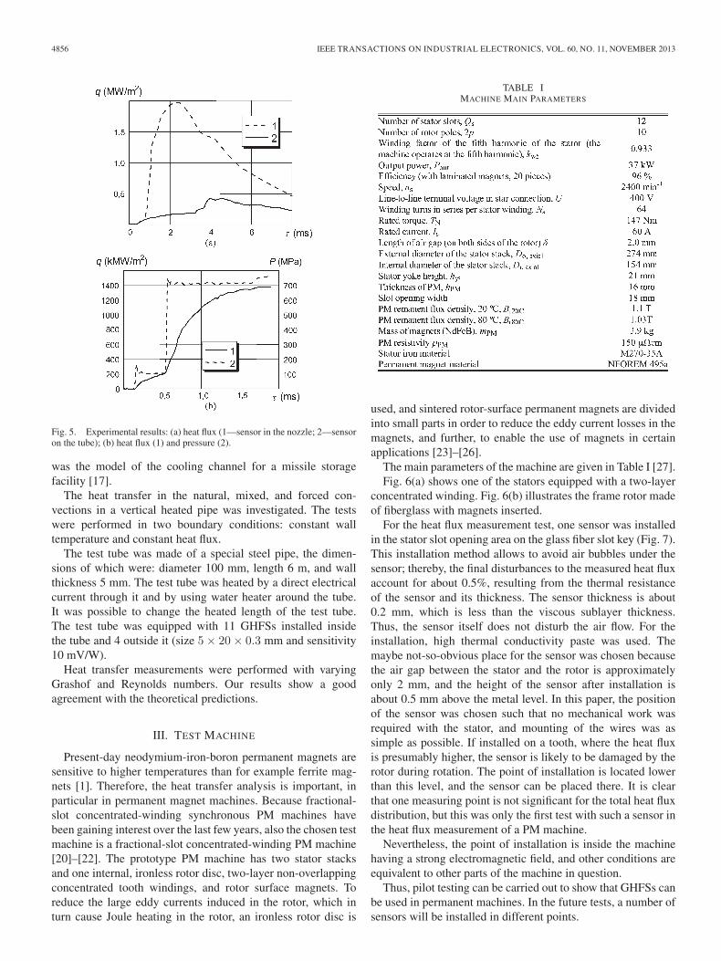
The measurement results on a cross section of 100 mm fromthe closed end are shown in Fig. 5. The pressure transducerpulse (dashed line) abruptly increases at the moments of pass-ing of the incident (τ = 0.15 ms) and reflected (τ = 0.55 ms)shock waves through the recording cross section. The heat fluxvariation (solid line) completely correlates in time with thepressure transducer signal. The heat flux density in the areaafter the reflected shock wave (where the gas temperature is∼7000 K) reaches 1.4 MW/m2. Both the transducers werepreliminarily calibrated: the measurement error of the HFS is∼2%, and the pressure transducer 10% at maximum.
Thus, the results showed that the GHFS can be used tomeasure intensive pulse heat loads related to supersonic andhypersonic gas dynamics. The results of the present study agreewell with the heat flux measurements performed with a thin-film resistance element.
4) Heat Transfer in the Mixed and Forced Convection in aVertical Heated Pipe (in Cooperation With Los-Alamos Na-tional Laboratory, USA): The vertical 6 m high heated pipe
4856 IEEE TRANSACTIONS ON INDUSTRIAL ELECTRONICS, VOL. 60, NO. 11, NOVEMBER 2013
Fig. 5. Experimental results: (a) heat flux (1—sensor in the nozzle; 2—sensoron the tube); (b) heat flux (1) and pressure (2).
was the model of the cooling channel for a missile storagefacility [17].
The heat transfer in the natural, mixed, and forced con-vections in a vertical heated pipe was investigated. The testswere performed in two boundary conditions: constant walltemperature and constant heat flux.
The test tube was made of a special steel pipe, the dimen-sions of which were: diameter 100 mm, length 6 m, and wallthickness 5 mm. The test tube was heated by a direct electricalcurrent through it and by using water heater around the tube.It was possible to change the heated length of the test tube.The test tube was equipped with 11 GHFSs installed insidethe tube and 4 outside it (size 5× 20× 0.3 mm and sensitivity10 mV/W).
Heat transfer measurements were performed with varyingGrashof and Reynolds numbers. Our results show a goodagreement with the theoretical predictions.
III. TEST MACHINE
Present-day neodymium-iron-boron permanent magnets aresensitive to higher temperatures than for example ferrite mag-nets [1]. Therefore, the heat transfer analysis is important, inparticular in permanent magnet machines. Because fractional-slot concentrated-winding synchronous PM machines havebeen gaining interest over the last few years, also the chosen testmachine is a fractional-slot concentrated-winding PM machine[20]–[22]. The prototype PM machine has two stator stacksand one internal, ironless rotor disc, two-layer non-overlappingconcentrated tooth windings, and rotor surface magnets. Toreduce the large eddy currents induced in the rotor, which inturn cause Joule heating in the rotor, an ironless rotor disc is
TABLE IMACHINE MAIN PARAMETERS
used, and sintered rotor-surface permanent magnets are dividedinto small parts in order to reduce the eddy current losses in themagnets, and further, to enable the use of magnets in certainapplications [23]–[26].
The main parameters of the machine are given in Table I [27].Fig. 6(a) shows one of the stators equipped with a two-layer
concentrated winding. Fig. 6(b) illustrates the frame rotor madeof fiberglass with magnets inserted.
For the heat flux measurement test, one sensor was installedin the stator slot opening area on the glass fiber slot key (Fig. 7).This installation method allows to avoid air bubbles under thesensor; thereby, the final disturbances to the measured heat fluxaccount for about 0.5%, resulting from the thermal resistanceof the sensor and its thickness. The sensor thickness is about0.2 mm, which is less than the viscous sublayer thickness.Thus, the sensor itself does not disturb the air flow. For theinstallation, high thermal conductivity paste was used. Themaybe not-so-obvious place for the sensor was chosen becausethe air gap between the stator and the rotor is approximatelyonly 2 mm, and the height of the sensor after installation isabout 0.5 mm above the metal level. In this paper, the positionof the sensor was chosen such that no mechanical work wasrequired with the stator, and mounting of the wires was assimple as possible. If installed on a tooth, where the heat fluxis presumably higher, the sensor is likely to be damaged by therotor during rotation. The point of installation is located lowerthan this level, and the sensor can be placed there. It is clearthat one measuring point is not significant for the total heat fluxdistribution, but this was only the first test with such a sensor inthe heat flux measurement of a PM machine.
Nevertheless, the point of installation is inside the machinehaving a strong electromagnetic field, and other conditions areequivalent to other parts of the machine in question.
Thus, pilot testing can be carried out to show that GHFSs canbe used in permanent machines. In the future tests, a number ofsensors will be installed in different points.

JUSSILA et al.: LOCAL HEAT FLUX MEASUREMENT IN A PERMANENT MAGNET MOTOR AT NO LOAD 4857
Fig. 6. (a) One stator equipped with windings. (b) Rotor with magnetsassembled.
Based on the heat transfer mechanisms, the heat flux vectoris always normal to the isotherm lines. Therefore, if the bodysurface has a constant temperature in a certain area, the heat fluxvector (including convection and radiation) is always normal tothe surface. Then, applying the conduction mechanism, the heatflux can be transferred into the body in any direction, but alwaysnormal to the isotherms.
As the sensor is installed on the surface, it measures the totalheat flux, passing through the sensor and coming in or out fromthe body. The sensor, thereby, cannot measure the heat fluxesinside the body.
IV. TEST RESULTS
The no-load tests were performed in the generator modeusing the DC machine drive as a prime mover. Fig. 8 illustratesthe test setup.
The no-load test was performed to evaluate the heat flux inone local point, the induced back-emf of the machine, statoriron losses, the Joule losses of the permanent magnets, andthe mechanical loss in no-load conditions. One sensor was
Fig. 7. (a) and (b) Heat flux sensor 10× 10 mm2, installed using thermalpaste on the stator slot wedge. The magnetic flux variation will be mostly alongthe line between the terminals, and therefore, the magnetic-flux-induced ACvoltage will come mainly from the sensor connection wires having a clear loopbefore being twisted. The sensor itself also has some loop surface, in which theAC noise voltage will be induced.
Fig. 8. No-load test arrangement for the concentrated winding axial flux PM.
Fig. 9. Temperatures of windings as a function of time at different rotationalspeeds.
used in our pilot tests as described above. At the moment, themeasurement is considered sufficiently accurate in one point.The main idea is to test the sensor and the option of usingit for on-line heat flux measurement inside permanent magnetmachines and similar electric drives.
The stator phase winding temperatures at no load at differentrotational speeds from 1200 to 2400 min−1 are shown in Fig. 9.Pt100 temperature sensors were used in the phase windings.The temperatures increased during the tests because of the heat
4858 IEEE TRANSACTIONS ON INDUSTRIAL ELECTRONICS, VOL. 60, NO. 11, NOVEMBER 2013
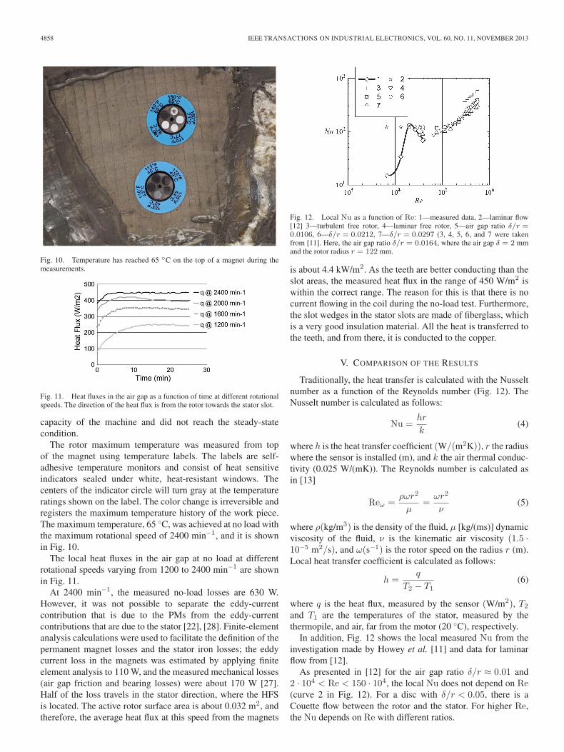
Fig. 10. Temperature has reached 65 ◦C on the top of a magnet during themeasurements.
Fig. 11. Heat fluxes in the air gap as a function of time at different rotationalspeeds. The direction of the heat flux is from the rotor towards the stator slot.
capacity of the machine and did not reach the steady-statecondition.
The rotor maximum temperature was measured from topof the magnet using temperature labels. The labels are self-adhesive temperature monitors and consist of heat sensitiveindicators sealed under white, heat-resistant windows. Thecenters of the indicator circle will turn gray at the temperatureratings shown on the label. The color change is irreversible andregisters the maximum temperature history of the work piece.The maximum temperature, 65 ◦C, was achieved at no load withthe maximum rotational speed of 2400 min−1, and it is shownin Fig. 10.
The local heat fluxes in the air gap at no load at differentrotational speeds varying from 1200 to 2400 min−1 are shownin Fig. 11.
At 2400 min−1, the measured no-load losses are 630 W.However, it was not possible to separate the eddy-currentcontribution that is due to the PMs from the eddy-currentcontributions that are due to the stator [22], [28]. Finite-elementanalysis calculations were used to facilitate the definition of thepermanent magnet losses and the stator iron losses; the eddycurrent loss in the magnets was estimated by applying finiteelement analysis to 110 W, and the measured mechanical losses(air gap friction and bearing losses) were about 170 W [27].Half of the loss travels in the stator direction, where the HFSis located. The active rotor surface area is about 0.032 m2, andtherefore, the average heat flux at this speed from the magnets
Fig. 12. Local Nu as a function of Re: 1—measured data, 2—laminar flow[12] 3—turbulent free rotor, 4—laminar free rotor, 5—air gap ratio δ/r =0.0106, 6—δ/r = 0.0212, 7—δ/r = 0.0297 (3, 4, 5, 6, and 7 were takenfrom [11]. Here, the air gap ratio δ/r = 0.0164, where the air gap δ = 2 mmand the rotor radius r = 122 mm.
is about 4.4 kW/m2. As the teeth are better conducting than theslot areas, the measured heat flux in the range of 450 W/m2 iswithin the correct range. The reason for this is that there is nocurrent flowing in the coil during the no-load test. Furthermore,the slot wedges in the stator slots are made of fiberglass, whichis a very good insulation material. All the heat is transferred tothe teeth, and from there, it is conducted to the copper.
V. COMPARISON OF THE RESULTS
Traditionally, the heat transfer is calculated with the Nusseltnumber as a function of the Reynolds number (Fig. 12). TheNusselt number is calculated as follows:
Nu =hr
k(4)
where h is the heat transfer coefficient (W/(m2K)), r the radiuswhere the sensor is installed (m), and k the air thermal conduc-tivity (0.025 W/(mK)). The Reynolds number is calculated asin [13]
Reω =ρωr2
μ=
ωr2
ν(5)
where ρ(kg/m3) is the density of the fluid, μ [kg/(ms)] dynamicviscosity of the fluid, ν is the kinematic air viscosity (1.5 ·10−5 m2/s), and ω(s−1) is the rotor speed on the radius r (m).Local heat transfer coefficient is calculated as follows:
h =q
T2 − T1(6)
where q is the heat flux, measured by the sensor (W/m2), T2
and T1 are the temperatures of the stator, measured by thethermopile, and air, far from the motor (20 ◦C), respectively.
In addition, Fig. 12 shows the local measured Nu from theinvestigation made by Howey et al. [11] and data for laminarflow from [12].
As presented in [12] for the air gap ratio δ/r ≈ 0.01 and2 · 104 < Re < 150 · 104, the local Nu does not depend on Re(curve 2 in Fig. 12). For a disc with δ/r < 0.05, there is aCouette flow between the rotor and the stator. For higher Re,the Nu depends on Re with different ratios.

JUSSILA et al.: LOCAL HEAT FLUX MEASUREMENT IN A PERMANENT MAGNET MOTOR AT NO LOAD 4859
Our measured data for 6000 < Re < 20 000 are lower thanthe predicted Nu. This may be explained by the fact that thesensor was installed in a cavity on the fiber insulation plates(see Fig. 7).
For 7000 < Re < 20 000, the local Nu increased from 15 to150. For 20 000 < Re < 40 000, the local Nu decreased from150 to 70, which is practically the same as curve 4 at the sameRe. The main difference here compared with [11] is that the Nunumber is measured in an actual PM machine, and the sensoris installed in a slot, which represents a down step in the flow.In our further research, we will increase the number of sensorsand install them in different points of the stator. Moreover, thetarget is to record high-speed heat flux pulsation and perform afrequency analysis.
VI. CONCLUSION
The paper describes the application of a local heat fluxmeasurement sensor based on the transverse Seebeck effectin the heat transfer measurement in an AFPM machine. Themeasurement data were first obtained with the HFS in a PMmotor. The sensor measurement results correspond well to theresults produced by the heat transfer model of the machine andalso to the Nu number analysis reported in different studiesin the literature. Direct heat flux measurements can signifi-cantly improve the opportunities to evaluate the heat transfer inelectrical machines and other heat transfer cases. However, theapplication of the sensor in different heat transfer cases requiresfurther research with several sensors installed in places that arethe most important ones from the heat transfer point of view,and also an in-depth analysis of the fluid flow in the air gap.
The heat flux measurement method offers a significant ca-pability of further developing electrical machines. Sensitivepermanent magnets can be protected in a totally new way whenexact heat flux components in the machine can be measured.Developing such a method to a level where the measurementresults are always reliable makes a breakthrough in the electri-cal machine development.
REFERENCES
[1] D. A Howey, P. R. N Childs, and A. S Holmes, “Air-gap convection inrotating electrical machines,” IEEE Trans. Ind. Electron., vol. 59, no. 3,pp. 1367–1375, Mar. 2012.
[2] J. Nerg, M. Rilla, and J. Pyrhönen, “Thermal analysis of radial-flux elec-trical machines with a high power density,” IEEE Trans. Ind. Electron.,vol. 55, no. 10, pp. 3543–3554, Oct. 2008.
[3] D. A. Howey, A. S. Holmes, and K. R. Pullen, “Measurement and CFDprediction of heat transfer in air-cooled disc-type electrical machines,”IEEE Trans. Ind. Appl., vol. 47, no. 4, pp. 1716–1723, Jul./Aug. 2011.
[4] “Omega (thin film heat flux sensor, self generating thermopile trans-ducer),” 2012. [Online]. Available: http://www.omega.co.uk/ppt/pptsc.asp?ref=HFS-3_HFS-4&flag=1
[5] D. A. Staton and A. Cavagnino, “Convection heat transfer and flow calcu-lations suitable for electric machines thermal models,” IEEE Trans. Ind.Electron., vol. 55, no. 10, pp. 3509–3516, Oct. 2008.
[6] A. Boglietti, A. Cavagnino, and D. Staton, “Determination of criticalparameters in electrical machine thermal models,” IEEE Trans. Ind. Appl.,vol. 44, no. 4, pp. 1150–1159, Jul./Aug. 2008.
[7] T. A. Jankowski, F. C. Prenger, D. D. Hill, S. R. O’Bryan, K. K. Sheth,E. B. Brookbank, D. F. A. Hunt, and Y. A. Orrego, “Development andvalidation of a thermal model for electric induction motors,” IEEE Trans.Ind. Electron., vol. 57, no. 12, pp. 4043–4054, Dec. 2010.
[8] A. Boglietti, A. Cavagnino, D. A. Staton, M. Shanel, M. Mueller, andC. Mejuto, “Evolution and modern approaches for thermal analysis ofelectric machines,” IEEE Trans. Ind. Electron., vol. 56, no. 3, pp. 871–882, Mar. 2009.
[9] F. Sahin and A. J. A. Vandenput, “Thermal modeling and testing of a high-speed axial-flux permanent-magnet machine,” COMPEL, Int. J. Comput.Math. Elect. Electron. Eng., vol. 22, no. 4, pp. 982–997, 2003.
[10] D. A. Howey, A. S. Holmes, and K. R. Pullen, “Radially resolved mea-surement of stator heat transfer in a rotor-stator disc system,” Int. J. HeatMass Transf., vol. 53, no. 1–3, pp. 491–501, Jan. 2010.
[11] D. A. Howey, A. S. Holmes, and K. R. Pullen, “Measurement of stator heattransfer in air-cooled axial flux permanent magnet machines,” in Proc.IEEE Annu. Conf. 35th Ind. Electron., Porto, Portugal, Nov. 3–5, 2009,pp. 1197–1202.
[12] S. Harmand, B. Watel, and B. Desmet, “Local convective heat exchangesfrom a rotor facing a stator,” Int. J. Thermal Sci., vol. 39, no. 3, pp. 404–413, Mar. 2000.
[13] C. H. Lim, G. Airoldi, R. G. Dominy, and K. Mahkamov, “Experimentalvalidation of CFD modelling for heat transfer coefficient predictions inaxial flux permanent magnet generators,” Int. J. Thermal Sci., vol. 50,no. 12, pp. 2451–2463, Dec. 2011.
[14] N. Divin, S. Sapozhnikov, and A. Kirillov, “Gradientenartige Mess-geber fur die Messung des Warmestromes,” in Proc. Messtechnik zurUndersuchung von Vorgangen in thermischen Energieanlagen. XXVIII.Kraftwerkstechnisches Kolloquium und 6. Kolloquium Messtechnik furEnergieanlagen, Dresden, Germany, 1996, pp. 155–160.
[15] S. Z. Sapozhnikov, V. Yu. Mityakov, A. V. Mityakov, A. I. Pokhodun,N. A. Sokolov, and M. S. Matveev, “The calibration of gradient heat fluxsensors,” Meas. Tech., vol. 54, no. 10, pp. 1155–1159, Jan. 2012.
[16] A. V. Mityakov, S. Z. Sapozhnikov, V. Y. Mityakov, A. A. Snarskii,M. I. Zhenirovsky, and J. J. Pyrhönen, “Gradient heat flux sensors forhigh temperature environments,” Sens. Actuators A, Phys., vol. 176, no. 1,pp. 1–9, Apr. 2012.
[17] M. A. Blinov, M. E. Lebedev, I. S. Muhina, L. A. Feldberg, B. S. Fokin,D. K. Zaitsev, E. L. Kitanin, S. F. Uras, and A. V. Mityakov, “Naturaland mixed convection heat transfer of a cooling air in fissile materialand spent fuel storage facilities,” Heat Transf. Res., vol. 36, no. 4, pp. 295–309, 2005.
[18] A. Zhukauskas, “Heat transfer from tubes in cross flow,” in Advances inHeat Transfer. New York: Academic, 1972.
[19] A. V. Mitiakov, V. Y. Mitiakov, S. Z. Sapozhnikov, andY. S. Chumakov, “Application of the transverse seebeck effect tomeasurement of instantaneous values of a heat flux on a vertical heatedsurface under conditions of free-convection,” High Temp., vol. 40, no. 4,pp. 620–625, Jul. 2002.
[20] A. M. EL-Refaie, “Fractional-slot concentrated-windings synchronouspermanent magnet machines: Opportunities and challenges,” IEEE Trans.Ind. Electron., vol. 57, no. 1, pp. 107–121, Jan. 2010.
[21] G. De Donato, F. Giulii Gapponi, and F. Caricchi, “No-load performanceof axial flux permanent magnet machines mounting magnetic wedges,”IEEE Trans. Ind. Electron., vol. 59, no. 10, pp. 3786–3779, Oct. 2012.
[22] R. Di Stefano and F. Marignetti, “Electromagnetic analysis of axial-flux permanent magnet synchronous machines with fractional windingswith experimental validation,” IEEE Trans. Ind. Electron., vol. 59, no. 6,pp. 2573–2582, Jun. 2012.
[23] H. Polinder and M. J. Hoeijmakers, “Eddy-current losses in the segmentedsurface-mounted magnets of a PM machine,” IET Elect. Power Appl.,vol. 146, no. 3, pp. 261–266, May 1999.
[24] H. Toda, Z. Xia, J. Wang, K. Atallah, and D. Howe, “Rotor eddy cur-rent loss in permanent magnet brushless machines,” IEEE Trans. Magn.,vol. 40, no. 4, pp. 2104–2106, Jul. 2004.
[25] W.-Y. Huang, A. Bettayeb, R. Kaczmarek, and J.-C. Vannier, “Opti-mization of magnet segmentation for reduction of eddy-current losses inpermanent magnet synchronous machine,” IEEE Trans. Energy Convers.,vol. 25, no. 2, pp. 381–387, Jun. 2010.
[26] F. Marighetti and R. Di Stefano, “Electromagnetic analysis of axial fluxpermanent magnet synchronous machines with fractional windings withexperimental validation,” IEEE Trans. Ind. Electron., vol. 59, no. 6,pp. 2573–2582, Jun. 2012.
[27] H. Jussila, “Concentrated winding multiphase permanent magnetmachine design and electromagnetic properties—Case axial flux ma-chine,” Ph.D. dissertation, Acta Universitatis Lappeenrantaensis 374,Lappeenranta Univ. Technol., Lappeenranta, Finland, 2009.
[28] A. Di Gerlando, G. Foglia, M. F. Iacchetti, and R. Perini, “Axial flux PMmachines with concentrated armature windings: Design analysis and testvalidation of wind energy generators,” IEEE Trans. Ind. Electron., vol. 58,no. 9, pp. 3795–3805, Sep. 2011.
4860 IEEE TRANSACTIONS ON INDUSTRIAL ELECTRONICS, VOL. 60, NO. 11, NOVEMBER 2013
Hanne K. Jussila was born in Kuusankoski,Finland in 1980. She received the M.Sc. andD.Sc. (Tech) degrees in electrical engineeringfrom the Lappeenranta University of Technology(LUT), Lappeenranta, Finland, in 2005 and 2009,respectively.
Currently, she is a Postdoctoral Researcher andTeacher with the Department of LUT Energy (Elec-trical Engineering). Her research interests includepermanent magnet machines, in particular concen-trated winding permanent magnet machines.
Andrey V. Mityakov was born in Leningrad, Russia,in 1974. He received the M.Sc. (Mech.Eng.), Ph.D.,and D.Sc. (Tech.) degrees from Leningrad (Saint-Petersburg) State Technical (Polytechnical) Univer-sity, Saint-Petersburg, Russia, in 1997, 2000, and2010, respectively.
From 1997 until 2010, he acted as an AssociateProfessor at the Department of Thermodynamics andHeat Transfer in Saint-Petersburg State Polytechni-cal University, Saint-Petersburg, Russia. Since 2010,he has been a Professor of the same university. In
the year 2011, he started his international work with a position of Professor inLappeenranta University of Technology (LUT) Institute of Energy Technologyat LUT, Finland. His research includes heat transfer (in particular measuringtechniques) and data acquisition systems.
Prof. Mityakov is a laureate of the Prize named after the first Rector ofSaint-Petersburg Polytechnical Institute, Prince A.G. Gagarin (1998), the medalfrom the Russian Union of Young Scientists “Devotion to the Science” (2008),winner of the Grant for Young Scientists from the President of the RussianFederation (2008), and Grant for Young Scientists from the Government ofSaint-Petersburg (2009).
Sergey Z. Sapozhnikov was born in Lvov, Ukraine,in 1950. He received the Mech.Eng. degree fromthe Krasnodar Polytechnical Institute, Krasnodar,in 1971, and the and D.Sc.(Tech.) degree fromthe Ural Polytechnical Institute, Sverdlovsk (nowYekaterinburg), Russia, in 1988.
Currently, he is a Professor at the Departmentof Thermodynamics and Heat Transfer in Saint-Petersburg State Polytechnical University, Saint-Petersburg, Russia. Prof. Sapozhnikov’s researchincludes material science (bimetals, composites),
heat transfer (thermal conductivity particularly), and thermophysicalexperiment.
Prof. Sapozhnikov is a laureate of the State Committee for High EducationPrize (1989); presently, he is a member of the Russian National Committeefor Heat Transfer, and a Fellow of the International Power Academy andInternational Academy of Refrigeration.
Vladimir Y. Mityakov was born in Leningrad,Russia, in 1951. He received the Mech.Eng. andD.Sc. (Tech) degrees at Leningrad Polytechni-cal Institute (Saint-Petersburg State PolytechnicalUniversity), Saint-Petersburg, Russia, in 1970 and2005, respectively.
Currently, he is a Professor at the Departmentof Thermodynamics and Heat Transfer in Saint-Petersburg State Polytechnical University, Saint-Petersburg, Russia. His areas of research include heattransfer phenomena in rotating channels.
Juha Pyrhönen (M’06) was born in Kuusankoski,Finland in 1957. He received the D.Sc. (Tech) degreefrom the Lappeenranta University of Technology(LUT), Lappeenranta, Finland, in 1991.
He became an Associate Professor of ElectricalEngineering at LUT in 1993 and a Professor ofelectrical machines and drives in 1997. Currently,he is the Vice Head of the Department of ElectricalEngineering, where he is engaged in the research anddevelopment of electric motors and electric drives.His current interests include different synchronous
machines and drives, induction motors and drives, and solid-rotor high-speedinduction machines and drives.