487 61-e high efficiency catalog 02 2010 - ramseyer · leser’s high efficiency product group...
TRANSCRIPT
Pilot Operated Safety Valve
Series 810 – Pop Action
Series 820 – Modulate Action
The-Safety-Valve.com
HighEfficiencyHighEfficiency

LESER’s High Efficiency Product Group
LESER’s High Efficiency Product Group consists of products that increase the efficiency and productivity of the protected plant.
These products are:
– Pilot Operated Safety Valves– Safety Valves with Supplementary Loading System
Highlights
LESER’s pilot operated safety valves are characterized by maintaining seat tightness closer to the set pressure.LESER’s pilot operated safety valves are distinguished by small opening and closing pressure differences. A solution that can be used worldwide in the market for pilot operated safety valves.
Approvals
LESER’s pilot operated safety valves can be used worldwide, as they are approved according to the following international codes and standards:
• European Community: CE marking as per Pressure Equipment Directive 97/23/EC and EN ISO 4126-4
• USA: UV-Stamp acc. to ASME Section VIII Division 1, National Board certified capacities
• Germany: VdTÜV approval as per Pressure Equipment Directive, EN ISO 4126-4, VdTÜV – Merkblatt SV 100/1
Regarding the design, manufacture and marking of LESER’s pilot operated safety valves, LESER also complies with the following regulations:
EN ISO 4126-7, EN 12266-1/-2, EN 1092 Part I and II, ASME PTC 25, ASME-Code Sec. II, ASME B16.34 and ASME B16.5,
API Std. 527, API RP 576
Applications
• Gas compressor stations
• Refineries
• Petrochemical industry
• Oil / gas – Onshore and Offshore
• Tank farms / tanker ships (LNG / LPG)
• Pulp and Paper industry
• Pumps
General InformationGeneral Information
LWN 487.61-E2
�
�
�

General InformationGeneral Information
LWN 487.61-E 3
Product Profile
LESER’s Pilot Operated Safety Valves
LESER’s series 810 and series 820 safety valves cover a wide spectrum of models, materials, and design features for any application:
• Design in compliance with API 526 for easy replacement.• Complete API 526 product range with valve sizes from
1" to 8", orifice D to T.• Body materials WCB, CF8M, LCB, 1.0619, 1.4408 and a
diversity of custom materials for an extended range of applications.
• One design and spring (single trim) for steam, gas and liquid applications reduces the number of spare parts and ensures low cost maintenance management.
• Back pressure independent construction allows for external back pressure > 50% of set pressure.
• Flange connections according to ASME, EN and JIS guarantee worldwide suitability.
LESER’s pilot operated safety valves offer a simple, safe solution for applications with
• high operating pressures in relation to the set pressure
• high back pressure
• high set pressures with large nominal diameters
• high capacities relating to the nominal diameter
• high seat tightness requirements with operating pressures that are close to the set pressure
Series 810 and Series 820
Depending on the design principle, LESER’s pilot operated safety valves open rapidly (Pop Action) or in proportion to the system pressure (Modulate Action). Pop Action pilot valves make up LESER’s Series 810 and the Modulate Action pilot valves make up LESER’s Series 820.
Series 810 – Pop Action
LESER’s Series 810 pop action pilot operated safety valves:
• are used mainly for vapour and gas applications where the maximum discharge capacity needs to be reached quickly.
• open completely within approx. 1% opening pressure difference and close within an adjustable blowdown of 2 – 7%.
• blowdown can be adjusted to 7% to 15% during plant oper-ation in order to guarantee safe functioning of the safety valve in cases of high pressure losses in the inlet line.
• have an adjustable blowdown of 2 – 7% conforming to ASME VIII with an optical marking feature.
• allow spring replacement in the pilot without complete disassembly of the pilot. This eliminates the need to remove the valve from service to change the set pressure.
Series 820 – Modulate Action
LESER’s Series 820 modulate action pilot operated safety valves:
• open in proportion to the overpressure to ensure that only as much mass flow as necessary is discharged from the safety valve to prevent further pressure increase.
• minimize medium losses. • open completely at an approximate 5 – 10% overpressure
and close within a blowdown of 2 – 7% for steam and gas applications.
LWN 487.61-E4
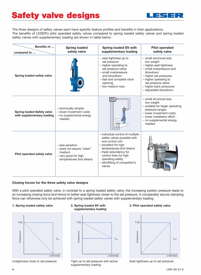
The three designs of safety valves each have specific feature profiles and benefits in their applications.The benefits of LESER’s pilot operated safety valves compared to spring loaded safety valves and spring loaded safety valves with supplementary loading are shown in table below.
Closing forces for the three safety valve designs
With a pilot operated safety valve, in contrast to a spring loaded safety valve, the increasing system pressure leads to an increasing closing force and hence to better seat tightness closer to the set pressure. A comparably secure clamping force can otherwise only be achieved with spring loaded safety valves with supplementary loading.
Safety valve designsSafety valve designs
Benefi ts of …
compared to …
Spring loaded
safety valve
Spring loaded SV with
supplementary loading
Pilot operated
safety valve
Spring loaded safety valve
– seat tightness up to set pressure
– higher operating to set pressure ratios
– small overpressure and blowdown
– fast and complete valve opening
– low medium loss
– small structural size, low weight
– higher seat tightness– small overpressure and
blowdown– higher set pressures– higher operating to
set pressure ratios– higher back pressures– adjustable blowdown
Spring loaded Safety valve
with supplementary loading
– technically simpler– lower investment costs– no supplemental energy
needed
– small structural size, low weight
– suitable for larger operating pressure ranges
– lower investment costs– lower installation effort– no supplemental energy
needed
Pilot operated safety valve
– less sensitive– does not require “clean”
medium– very good for high
temperatures (hot steam)
– individual control of multiple safety valves possible with one control unit
– excellent for high temperatures (hot steam)
– triple redundancy for control lines for high operating safety
– retrofi tting of competitor’s valves
3. Pilot operated safety valve
Seat tightness up to set pressure
F [N]
Clo
sing
fo
rce
Pset
p [bar/psig]
F [N]
Clo
sing
fo
rce
Pset
p [bar/psig]
1. Spring loaded safety valve
Untightness close to set pressure
F [N]
Clo
sing
fo
rce
Pset
p [bar/psig]
2. Spring loaded SV with
supplementary loading
Tight up to set pressure with active supplementary loading

LWN 487.61-E 5
Compressors in Gas Main Systems
Pilot operated safety valves are frequently used for gas transport in pipelines. The reasons are:
• highest possible operating pressure to set pressure ratios facilitates maximum energy density of transport medium
• vibrations from compressors lead to leakage with spring loaded safety valves
The Pop Action pilot valve is frequently used for gas applications.
Refineries and Gas Conditioning Plants
Pilot operated safety valves acc. to API 526 are fre-quently used in refineries. The reasons are:
• backpressure greater than 50% of set pressure because blow-down systems often include long pipe systems
• high absolute backpressures that cannot be handled with spring loaded safety valves with stainless steel bellows
In these applications, the backpressure-independent opening characteristic of LESER pilot valves guaran-tees reliable protection of the equipment.
Offshore Applications
On offshore platforms, more pilot operated safety valves than spring loaded safety valves are used. The reasons are:
• lower weight and lower overall height because, compared to a spring loaded safety valve, there is no bonnet
• high set pressures with larger orifices reduce the number of valves required
• no leakage with pilot operated safety valves means a low risk of fire
Pulp and Paper Industry
Pilot operated safety valves are used with steam-heated dryer drums, for example the Yankee Cylinder. The reasons are:
• operating pressures of the dryer drums should be as close as possible to the MAWP (Maximum Allowable Working Pressure) in order to increase plant productivity
• minimized overpressure and blowdown in order to avoid a paper tear caused by fluctuating saturated steam temperatures
• usability of LESER's pilot operated safety valves as an alternative to LESER supplementary loading
Pilot operated safety valves are used in a large variety of applications.Typical applications are:
ApplicationsApplications
6 LWN 487.61-E
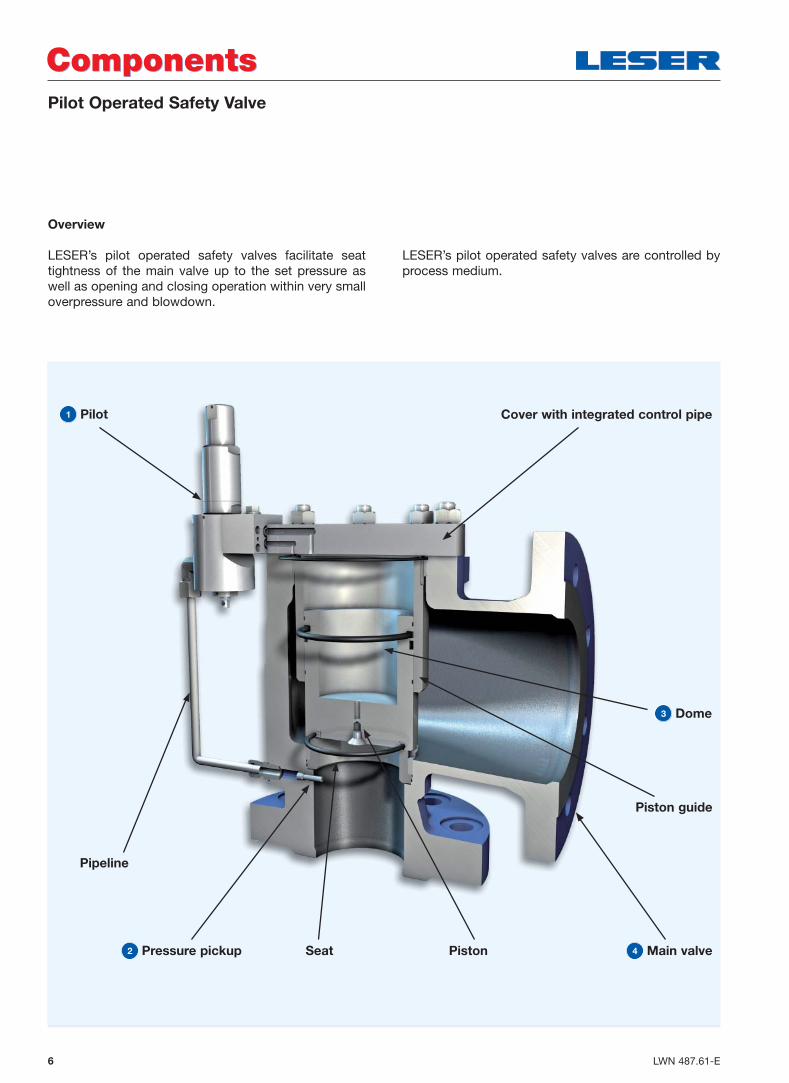
Pilot Operated Safety Valve
ComponentsComponents
Overview
LESER’s pilot operated safety valves facilitate seat tightness of the main valve up to the set pressure as well as opening and closing operation within very small overpressure and blowdown.
LESER’s pilot operated safety valves are controlled by process medium.
1 Pilot
Pipeline
Cover with integrated control pipe
3 Dome
Piston guide
4 Main valvePiston2 Pressure pickup Seat
7LWN 487.61-E
Pilot Operated Safety Valve
FunctionFunction
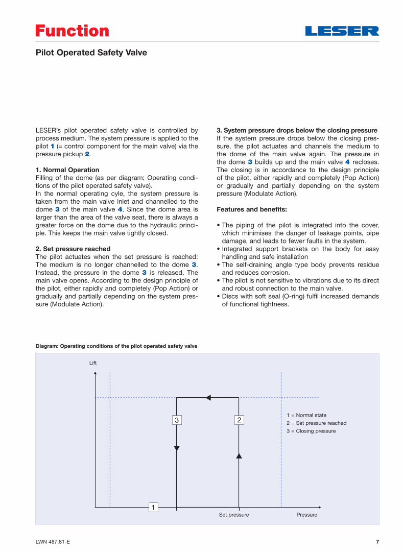
LESER’s pilot operated safety valve is controlled by process medium. The system pressure is applied to the pilot 1 (= control component for the main valve) via the pressure pickup 2.
1. Normal Operation
Filling of the dome (as per diagram: Operating condi-tions of the pilot operated safety valve).In the normal operating cyle, the system pressure is taken from the main valve inlet and channelled to the dome 3 of the main valve 4. Since the dome area is larger than the area of the valve seat, there is always a greater force on the dome due to the hydraulic princi-ple. This keeps the main valve tightly closed.
2. Set pressure reached
The pilot actuates when the set pressure is reached: The medium is no longer channelled to the dome 3.Instead, the pressure in the dome 3 is released. The main valve opens. According to the design principle of the pilot, either rapidly and completely (Pop Action) or gradually and partially depending on the system pres-sure (Modulate Action).
3. System pressure drops below the closing pressure
If the system pressure drops below the closing pres-sure, the pilot actuates and channels the medium to the dome of the main valve again. The pressure in the dome 3 builds up and the main valve 4 recloses. The closing is in accordance to the design principle of the pilot, either rapidly and completely (Pop Action) or gradually and partially depending on the system pressure (Modulate Action).
Features and benefits:
• The piping of the pilot is integrated into the cover, which minimises the danger of leakage points, pipe damage, and leads to fewer faults in the system.
• Integrated support brackets on the body for easy handling and safe installation
• The self-draining angle type body prevents residue and reduces corrosion.
• The pilot is not sensitive to vibrations due to its direct and robust connection to the main valve.
• Discs with soft seal (O-ring) fulfil increased demands of functional tightness.
1
3 21 = Normal state
2 = Set pressure reached
3 = Closing pressure
Diagram: Operating conditions of the pilot operated safety valve
Set pressure Pressure
Lift

8 LWN 487.61-E
Function
The Series 810 Pop Action pilot safety valve is char-acterized by rapid opening or pop action. Another typical terminology to characterize the function is “snap action”. The dome of the main valve is vented quickly and completely when the set pressure is reached; the main valve opens just as quickly and completely. The medium from the dome is discharged into the atmos-phere.
The Pop Action pilot safety valve is mainly used for vapour and gas applications.
Features and benefits
Robust and insensitive to vibrations. The robust con-nection of the pilot to the main valve and the reduced exposed piping guarantees safe operating even if there are vibrations in the system.
The spring is easily accessible by removing the top section of the bonnet only. This allows easy replace-ment of the spring and saves time and costs. Other functional parts or seals do not have to be disassem-bled and therefore do not need to be replaced.
Blowdown “failsafe”. Depending on the construction, the blowdown can only be adjusted in such a way that safe functioning of the pilot remains guaranteed. Even a maximum adjustment does not lead to the pilot having unstable behavior (e.g. fluttering).
Easy blowdown setting within the requirements of codes and standards. The blowdown range of 2 – 7%, which conforms to codes and standards, can easily be adjusted with the help of an optical marking feature on the pilot. Other test devices are not necessary.
A large pressure range of 2.5 – 63 bar (36 – 1480 psig) ensures that the Series 810 Pop Action pilot safety valve can be used for a multitude of applications.
Easy material replacement. The complete pilot is machined from bar material in 1.4404/316L. Hence, all parts can also be made of custom materials.
Series 810 – Pop Action PilotSeries 810 – Pop Action Pilot
Lift
Functional characteristics of Series 810 with Pop Action pilots
Set pressure
min. 3%
max. 15%
Adjustable blowdown
93% 100% 110% Pressure
Pilot-operatedsafety valve Series 810
LESER spring-loaded safety valvefor comparison only
9LWN 487.61-E
Function
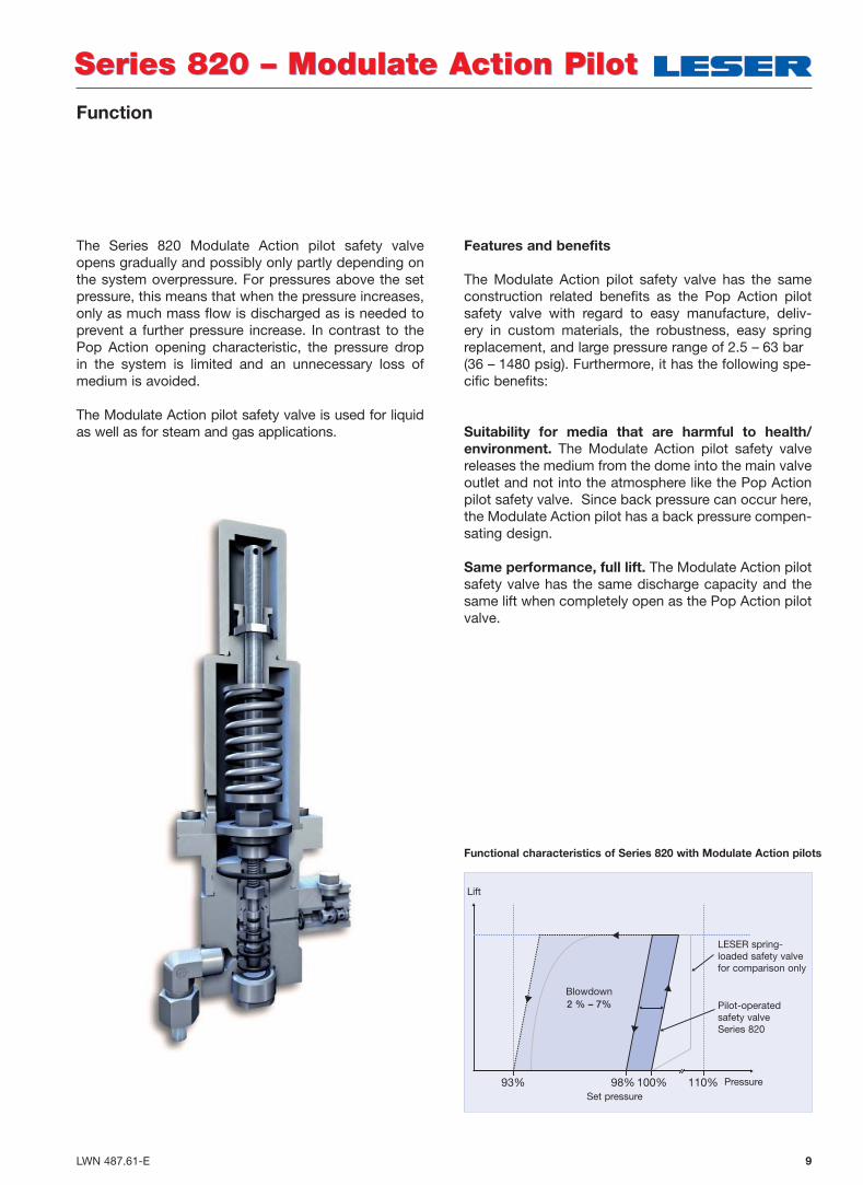
The Series 820 Modulate Action pilot safety valve opens gradually and possibly only partly depending on the system overpressure. For pressures above the set pressure, this means that when the pressure increases, only as much mass flow is discharged as is needed to prevent a further pressure increase. In contrast to the Pop Action opening characteristic, the pressure drop in the system is limited and an unnecessary loss of medium is avoided.
The Modulate Action pilot safety valve is used for liquid as well as for steam and gas applications.
Features and benefits
The Modulate Action pilot safety valve has the same construction related benefits as the Pop Action pilot safety valve with regard to easy manufacture, deliv-ery in custom materials, the robustness, easy spring replacement, and large pressure range of 2.5 – 63 bar (36 – 1480 psig). Furthermore, it has the following spe-cific benefits:
Suitability for media that are harmful to health/
environment. The Modulate Action pilot safety valve releases the medium from the dome into the main valve outlet and not into the atmosphere like the Pop Action pilot safety valve. Since back pressure can occur here, the Modulate Action pilot has a back pressure compen-sating design.
Same performance, full lift. The Modulate Action pilot safety valve has the same discharge capacity and the same lift when completely open as the Pop Action pilot valve.
Series 820 – Modulate Action PilotSeries 820 – Modulate Action Pilot
Functional characteristics of Series 820 with Modulate Action pilots
LESER spring-loaded safety valvefor comparison only
Pilot-operatedsafety valve Series 820
Lift
Set pressure
Blowdown2 % – 7%
93% 100%98% 110% Pressure

10 LWN 487.61-E
The following options for LESER’s pilot operated safety valves (810 and 820 series) facilitate further adaptations to specific operating conditions.
Solutions with OptionsSolutions with Options
Problem Solution with Option
Backfl ow preventer
Unwanted opening of the main valve from excess pressure in the discharge side (or low pressure at the pressure pickup)
Prevents unwanted opening of the main valve and hence a return flow of the medium from the discharge side into the system to be secured
Remote sensing
Chattering safety valve due to high pressure loss in the inlet line
• Pressure pickup is relocated from the main valve to the pipeline or the vessel
• The pilot safety valve works independently of pressure loss in the inlet line. That way, chattering of the safety valve is prevented
Field test connection
The set pressure is to be tested in the plant• Facilitates quick and easy checking of the set
pressure while the plant is in operation
Pilot supply fi lter
Dirty service
• Filters out solids in the process media, guarantees defined purity
• For liquid and gaseous media• Integrated into the inlet piping
Manual blowdown
Opening of the main valve is to be tested
• The function of the main valve is tested without the pilot having to execute a switching operation
• The dome pressure is released directly into the atmosphere
Pulsation damper
Unwanted opening of the main valve due to pulsations or pressure peaks
• Is integrated into the pressure sensing line between the pressure pickup and the inlet of the pilot with the medium flowing through it
• Dampens sudden pressure increases
Pilot lifting device H4
Because of codes and standards or customer requests, the function of the pilot and the main valve must be tested manually
• The main valve can be lifted manually with pilot lifting device H4
Note: The set pressure is not tested by manual lifting.
100 LWN 493.10-E
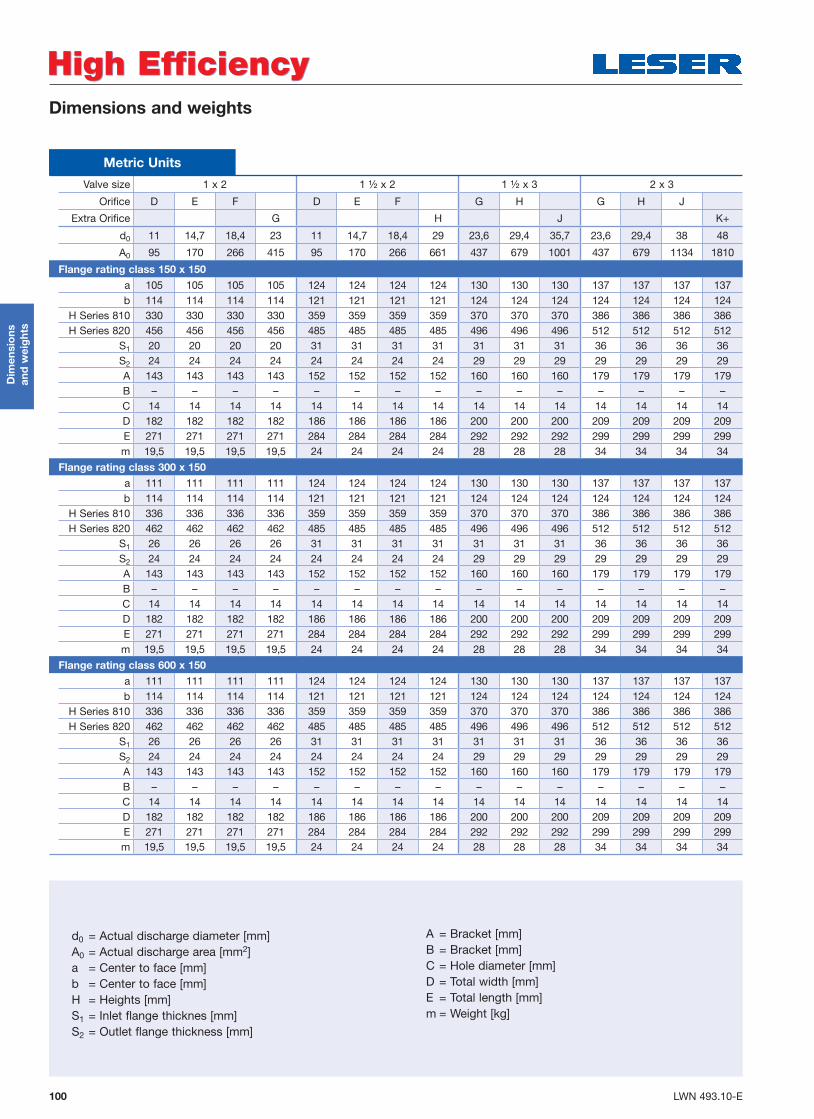
Dimensions and weights
Dim
ensi
ons
an
d w
eig
hts
High EfficiencyHigh Efficiency
Valve size 1 x 2 1 ½ x 2 1 ½ x 3 2 x 3
Orifice D E F D E F G H G H J
Extra Orifice G H J K+
d0 11 14,7 18,4 23 11 14,7 18,4 29 23,6 29,4 35,7 23,6 29,4 38 48
A0 95 170 266 415 95 170 266 661 437 679 1001 437 679 1134 1810
Flange rating class 150 x 150
a 105 105 105 105 124 124 124 124 130 130 130 137 137 137 137b 114 114 114 114 121 121 121 121 124 124 124 124 124 124 124
H Series 810 330 330 330 330 359 359 359 359 370 370 370 386 386 386 386H Series 820 456 456 456 456 485 485 485 485 496 496 496 512 512 512 512
S1 20 20 20 20 31 31 31 31 31 31 31 36 36 36 36S2 24 24 24 24 24 24 24 24 29 29 29 29 29 29 29A 143 143 143 143 152 152 152 152 160 160 160 179 179 179 179B – – – – – – – – – – – – – – –C 14 14 14 14 14 14 14 14 14 14 14 14 14 14 14D 182 182 182 182 186 186 186 186 200 200 200 209 209 209 209E 271 271 271 271 284 284 284 284 292 292 292 299 299 299 299m 19,5 19,5 19,5 19,5 24 24 24 24 28 28 28 34 34 34 34
Flange rating class 300 x 150
a 111 111 111 111 124 124 124 124 130 130 130 137 137 137 137b 114 114 114 114 121 121 121 121 124 124 124 124 124 124 124
H Series 810 336 336 336 336 359 359 359 359 370 370 370 386 386 386 386H Series 820 462 462 462 462 485 485 485 485 496 496 496 512 512 512 512
S1 26 26 26 26 31 31 31 31 31 31 31 36 36 36 36S2 24 24 24 24 24 24 24 24 29 29 29 29 29 29 29A 143 143 143 143 152 152 152 152 160 160 160 179 179 179 179B – – – – – – – – – – – – – – –C 14 14 14 14 14 14 14 14 14 14 14 14 14 14 14D 182 182 182 182 186 186 186 186 200 200 200 209 209 209 209E 271 271 271 271 284 284 284 284 292 292 292 299 299 299 299m 19,5 19,5 19,5 19,5 24 24 24 24 28 28 28 34 34 34 34
Flange rating class 600 x 150
a 111 111 111 111 124 124 124 124 130 130 130 137 137 137 137b 114 114 114 114 121 121 121 121 124 124 124 124 124 124 124
H Series 810 336 336 336 336 359 359 359 359 370 370 370 386 386 386 386H Series 820 462 462 462 462 485 485 485 485 496 496 496 512 512 512 512
S1 26 26 26 26 31 31 31 31 31 31 31 36 36 36 36S2 24 24 24 24 24 24 24 24 29 29 29 29 29 29 29A 143 143 143 143 152 152 152 152 160 160 160 179 179 179 179B – – – – – – – – – – – – – – –C 14 14 14 14 14 14 14 14 14 14 14 14 14 14 14D 182 182 182 182 186 186 186 186 200 200 200 209 209 209 209E 271 271 271 271 284 284 284 284 292 292 292 299 299 299 299m 19,5 19,5 19,5 19,5 24 24 24 24 28 28 28 34 34 34 34
Metric Units
d0 = Actual discharge diameter [mm]A0 = Actual discharge area [mm2] a = Center to face [mm]b = Center to face [mm]H = Heights [mm]S1 = Inlet flange thicknes [mm]S2 = Outlet flange thickness [mm]
A = Bracket [mm]B = Bracket [mm]C = Hole diameter [mm]D = Total width [mm]E = Total length [mm]m = Weight [kg]

101LWN 493.10-E
Dimensions and weights
Dim
ensi
ons
an
d w
eig
hts
High EfficiencyHigh Efficiency
Valve size 3 x 4 4 x 6 6 x 8 8 x 10
Orifice J K L L M N P Q R T
Extra Orifice N+ P+ R+ T+
d0 38 45 56 75 56 63 69 83 95 110 133 142 168 180
A0 1134 1590 2463 4418 2463 3117 3739 5411 7088 9503 13893 15837 22167 25447
Flange rating class 150 x 150
a 156 156 156 156 197 197 197 197 197 240 240 240 276 276b 162 162 162 162 210 210 210 210 210 241 241 241 279 279
H Series 810 428 428 428 428 481 481 481 481 481 580 580 580 668 668H Series 820 554 554 554 554 607 607 607 607 607 706 706 706 794 794
S1 36 36 36 36 49 49 49 49 49 52 52 52 45 45S2 29 29 29 29 30 30 30 30 30 47 47 47 35 35A 223 223 223 223 249 249 249 249 249 320 320 320 356 356B 110 110 110 110 110 110 110 110 110 160 160 160 160 160C 18 18 18 18 18 18 18 18 18 18 18 18 18 18D 259 259 259 259 305 305 305 305 305 381 381 381 430 430E 358 358 358 358 420 420 420 420 420 516 516 516 549 549m 56 56 56 56 86 86 86 86 86 192 192 192 260 260
Flange rating class 300 x 150
a 156 156 156 156 197 197 197 197 197 240 240 240 276 276b 162 162 162 162 210 210 210 210 210 241 241 241 279 279
H Series 810 428 428 428 428 481 481 481 481 481 580 580 580 668 668H Series 820 554 554 554 554 607 607 607 607 607 706 706 706 794 794
S1 36 36 36 36 49 49 49 49 49 52 52 52 45 45S2 29 29 29 29 30 30 30 30 30 47 47 47 35 35A 223 223 223 223 249 249 249 249 249 320 320 320 356 356B 110 110 110 110 110 110 110 110 110 160 160 160 160 160C 18 18 18 18 18 18 18 18 18 18 18 18 18 18D 259 259 259 259 305 305 305 305 305 381 381 381 430 430E 358 358 358 358 420 420 420 420 420 516 516 516 549 549m 56 56 56 56 86 86 86 86 86 192 192 192 260 260
Flange rating class 600 x 150
a 162 162 162 162 197 197 197 197 197 246 246 246 297 297b 162 162 162 162 210 210 210 210 210 241 241 241 279 279
H Series 810 434 434 434 434 481 481 481 481 481 586 586 586 689 689H Series 820 560 560 560 560 607 607 607 607 607 712 712 712 815 815
S1 42 42 42 42 49 49 49 49 49 58 58 58 66 66S2 29 29 29 29 30 30 30 30 30 47 47 47 35 35A 223 223 223 223 249 249 249 249 249 320 320 320 356 356B 110 110 110 110 110 110 110 110 110 160 160 160 160 160C 18 18 18 18 18 18 18 18 18 18 18 18 18 18D 259 259 259 259 305 305 305 305 305 381 381 381 430 430E 358 358 358 358 420 420 420 420 420 516 516 516 549 549m 56 56 56 56 86 86 86 86 86 192 192 192 260 260
Metric Units
A D
B
C
H
a
bE
S1
S2

5

6

Pilot Operated Safety ValveEdition April 2009
LWN 487.61-E / 04.2009 / 3000
20537 Hamburg, Wendenstr. 133-135
20506 Hamburg, P.O. Box 26 16 51
Fon +49 (40) 251 65-100
Fax +49 (40) 251 65-500
LESER GmbH & Co. KG E-Mail: [email protected]
www.leser.com
The-Safety-Valve.com