4998138538b d7212g program entry guide
TRANSCRIPT

Control/Communicator D7212G
Program Entry Guide

D7212GProgram Entry Guide
D7212G Program Entry Guide 4998138538B Page 2 © 2003 Bosch Security Systems

D7212GContents
D7212G Program Entry Guide © 2003 Bosch Security Systems Page 3 4998138538B
1.0 Introduction ...................................................................................................................................................................................... 71.1 How to use this Program Entry Guide .......................................................................................................................71.2 Other Literature Referenced.........................................................................................................................................71.3 Documentation Conventions ........................................................................................................................................71.3.1 Type Styles Used in this Guide ...................................................................................................................................71.3.2 Tips, Notes, Cautions and Warnings .........................................................................................................................81.4 Product Handlers ............................................................................................................................................................91.5 Programming Options....................................................................................................................................................91.6 Programming the Panel with the D5200 Programmer ........................................................................................ 101.6.1 Programming Error Displays...................................................................................................................................... 102.0 9000MAIN ........................................................................................................................................................................................112.1 Phone.............................................................................................................................................................................. 112.2 Phone Parameters ....................................................................................................................................................... 122.3 Routing ........................................................................................................................................................................... 162.3.1 Called Party Disconnect............................................................................................................................................. 162.3.2 Route # Groups, which has the highest priority?................................................................................................. 162.3.3 Programming a Primary and Backup Destination ................................................................................................. 162.3.4 Enhanced Routing ....................................................................................................................................................... 162.3.5 Programming a Duplicate report .............................................................................................................................. 162.3.6 Routing Destination Communication Failures ....................................................................................................... 162.3.7 Message Prioritization within a Route # ................................................................................................................. 172.3.8 Dialing Attempts........................................................................................................................................................... 172.4 Enhanced Routing ....................................................................................................................................................... 242.4.1 Programming a Primary and Backup Destination ................................................................................................. 242.4.2 Programming a Duplicate Report............................................................................................................................. 242.4.2.1 Numeric Pager Capability .......................................................................................................................................... 262.5 Power Supervision....................................................................................................................................................... 282.6 Printer Parameters ....................................................................................................................................................... 312.7 RAM Parameters .......................................................................................................................................................... 342.7.1 Uploading and Downloading Reports ..................................................................................................................... 342.7.2 Log Threshold Reports ............................................................................................................................................... 342.7.3 RAM Callback Reports ............................................................................................................................................... 342.8 Miscellaneous ............................................................................................................................................................... 372.9 Area Parameters........................................................................................................................................................... 382.9.1 Area Parameters........................................................................................................................................................... 382.9.1.1 Shared-Area Characteristics ..................................................................................................................................... 432.9.2 Bell Parameters ............................................................................................................................................................ 432.9.2.1 Bell Test after Confirmation ....................................................................................................................................... 462.9.2.2 Area Armed Confirmation........................................................................................................................................... 462.9.3 Open/Close Options................................................................................................................................................... 462.9.3.1 Account Opening and Closing Reports ................................................................................................................. 462.9.3.2 Area Opening and Closing Reports ........................................................................................................................ 462.9.3.3 Customizing Account Opening and Closing Reports ......................................................................................... 462.9.3.4 Combination Account and Area Opening and Closing Reports....................................................................... 462.9.3.5 Area Only Opening/Closing Supervision Features .............................................................................................. 47

D7212GContents
D7212G Program Entry Guide 4998138538B Page 4 © 2003 Bosch Security Systems
2.10 Command Center .........................................................................................................................................................502.10.1 Cmd Cntr (Command Center) Assignment ............................................................................................................502.10.2 Area Text .........................................................................................................................................................................542.10.3 Custom Function...........................................................................................................................................................552.10.3.1 Programming Custom Function Keystrokes ..........................................................................................................562.11 User Interface ................................................................................................................................................................582.11.1 Commands .....................................................................................................................................................................582.11.2 Command Center Selections.....................................................................................................................................582.11.2.1 Access Control Functions ..........................................................................................................................................612.11.2.2 Custom Functions.........................................................................................................................................................642.11.3 Authority Level Selections ..........................................................................................................................................642.11.3.1 Access Control Functions ..........................................................................................................................................682.11.3.2 Custom Functions.........................................................................................................................................................732.11.3.3 Report Levels.................................................................................................................................................................732.11.3.4 Access Control Levels.................................................................................................................................................742.12 Function List...................................................................................................................................................................752.13 Relay Parameters ..........................................................................................................................................................762.13.1 Area Relays ....................................................................................................................................................................772.13.2 Panel Wide Relays .......................................................................................................................................................803.0 RADXUSR1 .....................................................................................................................................................................................833.1 Passcode Worksheet ..................................................................................................................................................833.1.1 User Groups ..................................................................................................................................................................833.1.2 Passcodes......................................................................................................................................................................833.1.3 User Group Window....................................................................................................................................................833.1.4 Authority Level by Area................................................................................................................................................833.1.5 User Name......................................................................................................................................................................833.1.6 Reporting and Logging................................................................................................................................................844.0 RADXPNTS .....................................................................................................................................................................................874.1 Point Index ......................................................................................................................................................................874.1.1 Point Responses...........................................................................................................................................................904.2 Point Assignments..................................................................................................................................................... 1014.3 CMD 7 and CMD 9................................................................................................................................................... 1035.0 RADXSKED.................................................................................................................................................................................. 1055.1 Windows...................................................................................................................................................................... 1055.1.1 Opening & Closing .................................................................................................................................................... 1055.1.1.1 Holiday Indexes for O/C Windows........................................................................................................................ 1115.1.1.2 Opening/Closing Windows Worksheet ............................................................................................................... 1115.1.2 User Group Windows............................................................................................................................................... 1135.1.2.1 Holiday Indexes for User Group Windows .......................................................................................................... 1155.2 Skeds............................................................................................................................................................................ 1155.3 Holiday Indexes .......................................................................................................................................................... 1235.3.1 Add/Change/Delete .................................................................................................................................................. 1235.3.2 View Holidays ............................................................................................................................................................. 124

D7212GContents
D7212G Program Entry Guide © 2003 Bosch Security Systems Page 5 4998138538B
6.0 RADXAUX1...................................................................................................................................................................................1256.1 Introduction .................................................................................................................................................................1256.2 SDI Automation ..........................................................................................................................................................1256.3 SDI RAM Parameters................................................................................................................................................1286.3.1 User Interface Modifications for CMD 43 ............................................................................................................1286.3.2 Using an external modem.........................................................................................................................................1306.4 Enhanced Communications.....................................................................................................................................1356.4.1 Programming Path #'s and IP Addresses ............................................................................................................1356.5 SDI RAM/Enhanced Communications Configuration........................................................................................1396.5.1 Route Group Attempts .............................................................................................................................................1406.6 Miscellaneous .............................................................................................................................................................1416.7 Cross Point Parameters ...........................................................................................................................................142
FiguresFigure 1: Pager Display Fields...................................................................................................................................................... 26Figure 2: Example Opening Window Timeline (using 2 opening windows on same day) ...........................................108Figure 3: CMD 43 Flowchart ......................................................................................................................................................128Figure 4: RAM IP Address Prompts..........................................................................................................................................129Figure 5: Com Port Selection within HyperTerminal .............................................................................................................131Figure 7: Path # IP Add1 to Add4 ............................................................................................................................................136Figure 8: Poll Rate Timeline ........................................................................................................................................................137
TablesTable 1: Other Literature Referenced............................................................................................................................................7Table 2: Product Handlers ...............................................................................................................................................................9Table 3: Phone Number Data Entries ......................................................................................................................................... 11Table 4: Modem IIIa2 Communication Format data.................................................................................................................. 13Table 5: Diagnostic Reports ......................................................................................................................................................... 18Table 6: Burglar Reports................................................................................................................................................................ 19Table 7: User Reports .................................................................................................................................................................... 20Table 8: Test Reports Diag Reports ........................................................................................................................................... 21Table 9: Diagnostic Reports ......................................................................................................................................................... 21Table 10: Relay Reports ................................................................................................................................................................ 22Table 11: Auto-Function Reports................................................................................................................................................. 22Table 12: RAM Reports ................................................................................................................................................................. 22Table 13: Point Reports ................................................................................................................................................................. 23Table 14: User Change Reports.................................................................................................................................................. 23Table 15: Access Reports............................................................................................................................................................. 23Table 16: Event Descriptions, Priorities, and Numbers .......................................................................................................... 27Table 17: Battery Reports ............................................................................................................................................................. 30Table 18: Printer Scope................................................................................................................................................................. 31Table 19: Verify Time Example ..................................................................................................................................................... 41Table 20: Area Types ..................................................................................................................................................................... 42Table 21: Fire Bell Patterns........................................................................................................................................................... 44Table 22: Cmd Center # Dipswitch Settings ........................................................................................................................... 50Table 23: Command Center Scope............................................................................................................................................ 51Table 24: CF### Key Strokes..................................................................................................................................................... 56Table 25: CF### Custom Function Keystrokes...................................................................................................................... 56

D7212GContents
D7212G Program Entry Guide 4998138538B Page 6 © 2003 Bosch Security Systems
Table 26: Command Center Programming Choices................................................................................................................58Table 27: Master Arm Delay Programmable Examples ...........................................................................................................58Table 28: Authority Level Selections ...........................................................................................................................................64Table 29: BFSK Report per User Code......................................................................................................................................84Table 30: Point Types .....................................................................................................................................................................87Table 31: P## Pt Response - Controlled Points......................................................................................................................91Table 32: P## Pt Response – 24-Hour Points ........................................................................................................................91Table 33: P### BFSK/Relay Codes/Relays.......................................................................................................................... 102Table 34: Area Descriptions ....................................................................................................................................................... 108Table 35: Programming for Two Same-Day Opening Windows (see Timeline)............................................................. 108Table 36: Programming to Link Two Days over Midnight .................................................................................................... 109Table 37: W# Close Window Stop Programming Example ............................................................................................... 110Table 38: Opening/Closing Windows Worksheet ................................................................................................................ 112Table 39: Opening/Closing Windows...................................................................................................................................... 112Table 40: SDI Automation Parity and Stop Bits..................................................................................................................... 126Table 41: SDI Automation RTS Controls................................................................................................................................. 126Table 42: SDI Automation DTR Controls ................................................................................................................................ 126Table 43: Enhanced Communication Parity and Stop Bits ................................................................................................. 139Table 44: Enhanced Communication RTS Controls ............................................................................................................. 139Table 45: Enhanced Communication DTR Controls............................................................................................................. 140Table 46: Fire Supervision Restoral Events ............................................................................................................................ 141Table 47: Cross Point Ranges Within Groups....................................................................................................................... 142

IntroductionHow to Use this Program Entry Guide
D7212G Program Entry Guide © 2003 Bosch Security Systems Page 7 4998138538B
1.0 Introduction1.1 How to use this Program Entry GuideThis guide addresses the programming of the D7212G Control/Communicators only, and should not be used inconjunction with other panels.
1.2 Other Literature ReferencedThroughout this guide, references will be made to other documentation. See Table 1 below for a listing of the partnumbers for ordering purposes.
Bosch Security Systems recommends reading the following documents before installing and programming the products:
Name of document Part Number
D1255 Installation Instructions 74-06819-000
D1256/D1257 Installation Instructions 74-06925-000
D1260 Installation Guide 48101
D1260 Owner’s Manual 50410
D5200 Operation Manual 74-06176-000
D6500 Report Directory 74-04651-001
D6600 Communications Receiver/Gateway Computer Interface Manual 39963
D720 Installation Instructions 74-06918-000
D7212G Operation and Installation Guide 4998138544
D7212G Program Record Sheet 4998138542
RAM IV Operation Manual 38849
Table 1: Other Literature Referenced
1.3 Documentation Conventions1.3.1 Type Styles Used in this GuideTo help identify important items in the text, the following type styles are used:
Bold text Usually indicates selections that you may use while programming your panel. Itmay also indicate an important fact that should be noted.
Italicized text Is used to reference the user to another part of this guide or another guideentirely. It is also used to symbolize names for records that the user will create.
Courier Text Text that appears like this indicates what may appear on the RemoteProgrammer’s display, command center/keypad or internal printer.
[CAPITALIZED TEXT] Text like this is used to indicate to the user that a specific key should be pressed.
Italicized Text Text that appears like this indicates what would be seen in the RemoteProgrammer’s Display. It is used as a section heading and screen example. Shadedboxes indicate programmer prompts that are only available when Custom orView Events are selected.
Italicized Text A thick border is used to indicate a main programming entry.
Italicized Text A heavy dashed border is used to indicate a sub entry that is under a mainprogramming entry.

IntroductionDocumentation Conventions
D7212G Program Entry Guide 4998138538B Page 8 © 2003 Bosch Security Systems
1.3.2 Tips, Notes, Cautions and WarningsThroughout this document helpful tips and notes will be presented concerning the entire application and/orprogramming the unit. They will be set off as follows:
ApplicationTip
These are helpful shortcuts or reminders in using the unit.
Application
Note
These are notes and clarifications of different aspects of the application.
Programming
Note
010101010101 These cover notes and clarifications specific to programming the unit.
ProgrammingTip
010101010101 These are helpful shortcuts or reminders in programming the unit.
These notes should be heeded for successful operation and programming.
These warn of the possibility of physical damage to the operator, program and/or equipment.
These caution the operator that physical damage to the program and/or equipment may occur.

IntroductionProduct Handlers
D7212G Program Entry Guide © 2003 Bosch Security Systems Page 9 4998138538B
1.4 Product HandlersThe programming of the D7212G requires multiple product handlers. The availability of each handler is indicated inTable 3. Please refer to the panel specific Release Notes to determine the most up-to-date handler versions.
Product Handler Functionality D7212G
9000MAIN Covers Panel Wide, Area, Command CenterFunction List, User Interface, and Relayprogramming modules.
�
RADXUSR1 Covers Passcode/Token programming for Users000 through 99.
�
RADXPNTS Covers Point Index and Point Assignmentprogramming for all points.
�
RADXSKED Covers Open/Close Windows, User AccessWindows, Skeds, and Holiday Index programmingmodules.
�
RADXAUX1 Covers SDI Automation, SDI RAM Parameters,Enhanced Communication Parameters, RouteGroup Attempts, Miscellaneous, and Cross PointParameters.
�
Table 2: Product Handlers
Application
Note
Although the handlers shown above can be used to program any of the new D7212G Control/Communicators, not all of the functions will operate. For example, the RADXUSR1 Handler is used toprogram users 000 through 124. Even though the handler allows you to program users 100 through 124, theD7212G will not allow the activation of these users.
1.5 Programming OptionsThe Program Entry Guide has been set up in a specific order. Related program entries are grouped together in modules asthey appear in the specific product handlers. The handler and the programming module are listed at the top of each pageto help you find specific programming prompts.
The Program Entry Guide shows the programming options for each product handler. Each option is listed with:
• The program item Prompt. Each Prompt is shown, as it will appear in the D5200 Programmer, see theD5200 Programmer Manual, (P/N: 74-06176-000) or the Remote Account Manager, see the RAM IVOperations Manual, (P/N: 38849). Sometimes, for space considerations, a Prompt must be abbreviated inthe Programmer display. In these cases, the meaning of the prompt is explained in the Description.
• Program Entry Default setting. Since defaults are set for the typical installation, you may not need toprogram each prompt. Review the default entries in the Program Record Sheet shipped with the panel todetermine which prompts need to be programmed.
• Program Entry Selections. Only the selections listed can be used for a particular program item. Theprogrammer does not accept inappropriate entries.
• Program Entry Description. This provides concise information regarding what can occur with the variousentry selections. Read the Descriptions carefully as misunderstanding can result in improperly programmedequipment.
• Custom Programming. A new feature of the D5200 Programmer is the option to select Customprogramming Yes or No] to expand programming modules within the D5200. Programming Custom asYes does not affect the programming of any parameter. It allows parameters for special applications to bevisible in the programmer.

IntroductionDocumentation Conventions
D7212G Program Entry Guide 4998138538B Page 10 © 2003 Bosch Security Systems
1.6 Programming the Panel with the D5200 Programmer1. Latch the jumper in the upper right hand corner of the panel labeled as “RESET” on the PCB and “Reset
Pin” on the faceplate.2. Connect the molex end of the cord to the connector labeled as “PROG” on the PCB and “PROG CONN”
on the faceplate.3. Always initiate a panel copy at the NEW RECORD prompt or FILENAME when pressing the [RECV]
(copy) key of the D5200.4. Always initiate a panel load within the FILENAME or to set as factory default within the NEWRECORD
when pressing the [SEND] (load) key.5. Disconnect the D5200 prior to releasing the “RESET” pin or the SDI devices will go into trouble and display
CALL FOR SERVICE.
Do not leave the D5200 connected to the PROG connector without the “RESET” pin latched. Doing so willcause SDI ## TROUBLE reports and CALL FOR SERVICE to display on the command centers. Doorcontrollers will also activate depending upon the SDI failure dipswitch setting.
1.6.1 Programming Error DisplaysINCOMPATIBLE PANEL You are connected to the wrong panel or using the wrong handler. Check the
faceplate for the model number and the handler title.
CHECK CORD/RESETPIN
Check the cord and “RESET” pin
Programming
Tip
010101010101
There will be a 5 to 25 second pause after the “RESET” pin is unlatched during which the panel scans all thepoints and properly displays, logs and reports them.

9000MAINPhone
D7212G Program Entry Guide © 2003 Bosch Security Systems Page 11 4998138538B
2.0 9000MAINUse this programming module to define the operating characteristics that affect panel wide functions. There are nineprogramming categories in this module: Phone, Phone Parameters, Routing, Enhanced Communications, Area Parameters,Command Center, User Interface, Function List, and Relay Parameters.
2.1 PhoneThe panel can dial up to four different telephone numbers when sending event reports. All telephone numbers use thesame receiver format. Event report routing and communication protocols are discussed in Section 2.3 Routing on page 16.
Phone 1
Default: (Blank)Selections: Up to 24 characters (do not enter [SPACE])
This is the telephone number the panel dials to contact the central station receiver when sending event reports. Thisnumber is “Phone 1” which is referenced in Routing parameters.
The panel is pre-programmed with a 7 second dial tone detect period. When dial tone is detected or the waiting periodends, the panel begins to dial. To extend the dial tone detect program, place a D before the phone number. To insert apause during or after dialing, use C in the number sequence. For example, if the panel hangs up before it hears theModem IIIa2 Ack tone from the D6500/D6600, program extra Cs after the phone number. The panel waits on line forthree extra seconds for each C programmed.
Enter up to 24 of the following characters to define dialing characteristics.
Programming
Tip
010101010101
Using both Phone data entry lines: The first line of the phone number data entry line must be filled (twelvecharacters) before you press the [ENT] key to move on to the second line. If you enter characters on the secondline, and there are less than twelve characters on the first line, the second line clears when you press [ENT].
0 - 9 Numbers zero through nine
C 3 second pause
D 7 second dial-tone detect.
# or * Used for the same purpose as pressing this key on a telephone keypad when manuallydialing. For example, an asterisk (*) may be needed to access your long distance service. Donot use these characters when pulse dialing.
(Blank) Panel dials no phone number.Programming this item (Blank) does not disable phone routing. To disable reporting to thisphone refer to Section 2.3 Routing on page 16.
Table 3: Phone Number Data Entries
Phone 2
Default: (Blank)Selections: Up to 24 characters (do not enter [SPACE])
(See explanation of Phone 1.) This number is “Phone 2” which is referenced in Section 2.3 Routing on page 16.
Phone 3
Default: (Blank)Selections: Up to 24 characters (do not enter [SPACE])
(See explanation of Phone 1.) This number is “Phone 3” which is referenced in Section 2.3 Routing on page 16.

9000MAINPhone Parameters
D7212G Program Entry Guide 4998138538B Page 12 © 2003 Bosch Security Systems
Phone 4
Default: (Blank)Selections: Up to 24 characters (do not enter [SPACE])
(See explanation of Phone 1.) This number is “Phone 4” which is referenced in Section 2.3 Routing on page 16.
2.2 Phone ParametersThe program items in this category describe panel wide characteristics for telephone dialing, receiver format, andsupervision.
Modem Format
Default: YesSelections: Yes or No
Central Station Receiver Format for transmission of reports. Modem format provides many reporting advantages overthe BFSK format. See the D6500/D6600 Report Directory for more information about the effect of reporting formats.
Yes Modem IIIa2 Communication Format.Modem IIIa2 Communication Format reports identify points as “001” through “040” andpasscode User ID codes as “000” through “099” at the D6500/D6600 Receiver (unlessPoint/User Flag is programmed Yes; see below). When reporting point events, ModemIIIa2 Communication Format also sends point text to the D6500/D6600 as programmed inPoint Assignments.
No BFSK (2300 Hz or 1400 Hz acknowledgment tone).
Modem Format must be set to Yes when sending events over a network to a D6600 receiver(NetCom).
Programming
Tip
010101010101
If Modem Format is No, be sure to assign a number to identify duress reports in BFSK Duress Code inthis programming section.
Point/User Flag
Default: NoSelections: Yes or No
This program item determines how point and User ID numbers are presented at the D6500/D6600 display, printer, andcomputer RS232 output.
When Modem Format is Yes, the panel sends expanded Modem IIIa2 Communication Format reports to theD6500/D6600. If your central station data files are not set up for point and User ID number reporting, you can use thisprogram item to convert these numbers to COMEX reports.
Yes The panel sends a "flag" with each report that tells the D6500/D6600 to convert pointnumbers and User ID numbers to COMEX format. The conversions are shown in Table 4on page 13. [No matter how the D6500/D6600 is programmed for output to the computersystem, points and User ID numbers are converted when this item is Yes. (See the D6600Communications Receiver/Gateway Computer Interface manual, Appendix C, NumberedTable & Note 1.)]
No The panel does not send the “flag.” The D6500/D6600 outputs point numbers as 001 - 040(rather than 100 - 216) and User ID numbers as 000 - 099 (rather than 000 - F08), asindicated in Table 4 on page 13.
When Modem Format is Yes, the panel sends expanded Modem IIIa2 Communication Format reports to the receiver.Point/User Flag affects Modem IIIa2 Communication Format data as shown below. The Bosch Security SystemsD6500/D6600 Receiver adds the leading zero in the User ID Number with Point/User Flag programmed No.

9000MAINPhone Parameters
D7212G Program Entry Guide © 2003 Bosch Security Systems Page 13 4998138538B
User ID Numbers Point Numbers
Point/User Flag Point/User Flag
No Yes No Yes
000 000
001 – 005 001 – 005 001 – 008 100 – 800
006 – 013 601 – 608 009 – 024 101 – 116
014 – 021 701 – 708 025 – 040 201 – 216
022 – 029 801 – 808
030 – 037 B01 – B08
038 – 045 C01 – C08
046 – 053 D01 –D08
054 – 061 E01 – E08
062 – 069 F01 – F08
070 – 099 000
Table 4: Modem IIIa2 Communication Format data
Independent Zone Control Notice: When using Independent Zone Controls (I.Z.C.) to send opening/closing reports bypoint, do not duplicate reporting independent point numbers with User ID reports (refer to Section 3.1 PasscodeWorksheet on page 83). For example: If an I.Z.C. is connected to point 8, User ID 8 should not be used.
D6000: Opening/Closing User ID numbers are identified at the receiver as "ZONEs" (same identification as independentpoints).
User ID 1 = ZONE B User ID 6 = ZONE 6 User ID 93 = ZONE 3
User ID 2 = ZONE C User ID 7 = ZONE 7 User ID 94 = ZONE 4
User ID 3 = ZONE D User ID 8 = ZONE 8 User ID 95 = ZONE 5
User ID 4 = ZONE E User ID 91 = ZONE 1 User ID 96 = ZONE 0
User ID 5 = ZONE F User ID 92 = ZONE 2
D6500/D6600 Receiving BFSK format: Opening/closing User ID numbers are identified at the receiver as "ZN" (sameidentification as independent points). The "ZN" numbers are based on the “tens” digit of the User ID number. This onlyapplies for Users 000 through 099.
DTMF Dialing
Default: YesSelections: Yes or No
Use DTMF (dual-tone multi-frequency) to dial the central station receiver phone number(s) for event reports, and/or theRAM IV Remote Account Manager.
Yes Dials the programmed phone number(s) using DTMF.
No Pulse Dialing only

9000MAINPhone Parameters
D7212G Program Entry Guide 4998138538B Page 14 © 2003 Bosch Security Systems
Phone Supv Time
Default: (Blank)Selections: (Blank) or 10 - 240
The panel tests the primary phone line approximately nine times a minute and the secondary line once a minute. Thisprompt sets the amount of time the panel continues to monitor a faulted phone line before initiating phone line troubleresponses.
(Blank) No phone line supervision.
10 - 240 Enter the number of seconds (in 10 second increments) you wish to supervise the phoneline. After a faulted phone line restores, it takes the same amount of time to initiaterestoral responses.
Phone line trouble responses:
Command centers display SERVC PH LINE # to indicate which phone line failed. The command center will initiate atrouble tone if Buzz on Fail is Yes and CC Trouble Tone is Yes.
Phone trouble and restoral events report when they occur. They report also when a diagnostic report is initiated from acommand center or by a Sked.
Alarm On Fail
Default: NoSelections: Yes or No
Yes Generate alarm responses when a phone line fails.
No Phone failures will report as trouble responses for Area 1 and/or the account number forArea 1.
Programming
Tip
010101010101 Phone Supv Time must be programmed to use this feature.
Application
Note
Phone Failure Alarm Responses: The Alarm Bell relay for Area 1 activates. All phone event messages reportas Area 1 and/or the account number for Area 1.
Buzz On Fail
Default: NoSelections: Yes or No
Yes Generate panel wide trouble tones and display PHONE FAIL # at command centerswhen a Phone Fail event occurs.
No Does not generate trouble tones at command centers when a Phone Fail event occurs.PHONE FAIL # will still display.
Programming
Tip
010101010101 Phone Supv Time must be programmed to use this feature.
Application
Note
How to de-select individual command centers for panel wide trouble tones. Panel wide trouble tones forprogramming CC can turn off individual command centers (based on their CC # 1 through 8) # TroubleTone in Command Center Parameters as No.

9000MAINPhone Parameters
D7212G Program Entry Guide © 2003 Bosch Security Systems Page 15 4998138538B
Two Phone Lines
Default: NoSelections: Yes or No
Note: Not available with D7212G. Leave default.
BFSK Duress Code
Default: 0Selections: 0-9
If Duress Enable in Area Parameters is Yes and Modem Format in Phone Parameters is No, you must program a numberto identify duress reports at the central station.
Expand Test Rpt
Default: NoSelections: Yes or No
This program item is used to add system event information to scheduled test reports. Test reports are set up as scheduledevents in the Skeds Parameters section of the program.
Yes Report events listed in routing group test reports will report to the central station if theyare off-normal.
No Does not report off-normal conditions for the events listed in the routing group testreports at test time.
Application
Note
This parameter is related only to Sked Function Code 9 (Test Report) and whether this Sked will transmitExpanded Test Report information or not. It does NOT have any bearing on Sked Function Codes 28(Expanded Off-Normal Test Report) and 29 (Non-Expanded Off-Normal Test Report).
Ground Start
Default: LongSelections: Short or Long
Some newer ground start telephone exchange switches require a shorter amount of time to initiate dial tone. If the panelcan’t initiate a dial tone on the ground start line with the default (Long) setting, try the Short setting.
Long Standard duration of ground. Use this setting for most ground start telephone systems.The duration is 700 milliseconds.
Short Shorter duration of ground. Use this setting for telephone systems where specified. Theduration is 250 milliseconds.
Press the [SPACE] bar to scroll through the selections. Press [ENT] when the correct selection appears in the display.
Use this program item only when the panel is connected to Ground Start telephone lines. Ground Start is notallowed on UL Listed Systems.

9000MAINRouting
D7212G Program Entry Guide 4998138538B Page 16 © 2003 Bosch Security Systems
2.3 RoutingRouting lets you select full or partial groups of events to be reported to up to four different destinations. Routing includeschoosing which is the most important destination, (Route #), which events are reported to a single or multipledestination and if the events fail, which backup destination should be selected.
2.3.1 Called Party DisconnectTelephone companies provide “called party disconnect” to allow the called party to terminate a call. The called partymust go on hook (hang up) for a fixed interval before a dial tone is available for a new call. This interval varies withtelephone company equipment. D7212G firmware allows for “called party disconnect” by adding a 35 second “on hook”interval to the dial tone detect function. If the panel does not detect a dial tone in 7 seconds, it puts the phone line onhook for 35 seconds to activate “called party disconnect,” goes off hook and begins a 7 second dial tone detect. If no dialtone is detected, the panel dials the number anyway. Each time the number is dialed, the panel records this as an attempt.After ten attempts the panel goes into Communications Failure and Comm Fail Route # is displayed on thecommand centers.
2.3.2 Route # Groups, which has the highest priority?To program a group, you first choose a Route #. The lower the Route # number, the higher priority that group will have(e.g., events reported for Route 1 have a higher priority than Route 2, 3 or 4 if each group has a message to send at thesame time). This will become important when programming duplicate reports or choosing which events you want toensure will report first regardless of the number of events that need to be reported to multiple groups.
Remember that Route 1 group Primary Device will be the first destination that the panel will attempt to dial if an event inthat group needs to be reported. If the panel is idle, any event generated for any group will initiate a dialing sequence.
2.3.3 Programming a Primary and Backup DestinationEach Route # has an R# Primary Device and an R# Backup Device. In typical applications where two phone numbers areprogrammed, the R# Primary Device destination is the Phone # that the Route Group will attempt to dial first. If the R#Primary Device destination fails to connect to the central station receiver after two dialing attempts, then the R# BackupDevice destination will be dialed. In addition to this, the control panel can be programmed such that the R# PrimaryDevice and/or the R# Backup Device can be an SDI device, such as a D9133TTL-E Network Interface Module. Thecontrol panel can also be programmed to attempt only once for the R# Primary Device before attempting to send eventsusing the R# Backup Device.
2.3.4 Enhanced RoutingThe D7212G allow events to be transmitted to up to four Phone Numbers and/or “SDI Paths”. The D9133TTL-ENetwork Interface Module (with Ethernet) connects directly to the SDI Bus and occupies SDI Address 88. For additionalinformation regarding the specific programming requirements for enhanced communications, refer to Section 2.4Enhanced Routing on page 24 and Section 6.4 Enhanced Communications on page 135.
2.3.5 Programming a Duplicate reportTo allow an event within a group to report to multiple groups, the event should be Yes for each Route # available. Forinstance, programming Fire Alarms for Route Group 1 and Route Group 2 will result in the fire alarms first reporting toRoute Group 1 followed by a duplicate report to Route Group 2.
2.3.6 Routing Destination Communication FailuresWhen the R# Primary Device fails to connect with the central station after one or two attempts (see also RG# 1 Attempt),the R# Backup Device Phone # or SDI Path will be attempted. The central station will receive the original event with aCOMM FAIL PHONE# = (1, 2, 3, or 4) if the R# Primary Device destination is a phone number. If the R# PrimaryDevice is an SDI Path, the central station will receive the original event with
A COMM FAIL RG# SDI## (SDI Path 1 = 88, SDI Path 2 = 89, SDI Path 3 = 90, SDI Path 4 = 91). When all attemptsto both the R# Primary Device and R# Backup Device have failed, a COMM FAIL RG# event is generated. CommRestore events are not generated.

9000MAINRouting
D7212G Program Entry Guide © 2003 Bosch Security Systems Page 17 4998138538B
2.3.7 Message Prioritization within a Route #Fire alarm events have the highest priority and are reported first for each group. The next highest priority events are inthe following order, panic, duress, medical, intrusion ala
rm, supervisory and then all troubles and restorals.
Programming
Tip
010101010101
To comply with NFPA and UL985, you must program Route 1 to report only Fire Alarm events to ensure thefastest reporting time.
2.3.8 Dialing AttemptsThe D7212G panel has a prompt called RG# 1 Attempt located in Section 6.5.1 Route Group Attempts in theRADXAUX1 handler on page 140.
If this item is set to No the panel will make a total of six individual attempts to make contact using the primary devicewithin a Route Group and then will make a total of four attempts to make contact using the backup device beforeinitiating a Comm Fail report. When only one destination is programmed, the panel will make ten attempts to contactthat destination. Each group takes approximately 10 minutes to go into Comm Fail.
However, if this item is set to Yes, the panel will only make one attempt (instead of two) to contact the primary devicebefore attempting to contact the backup device. The Route Group still makes a total of ten attempts; however, thePrimary Device makes five attempts and then the Backup Device makes five attempts.
Route #
Default: 1Selections: 1 – 4
Enter the number specifying the route group to be programmed. The route represents the group you wish to send agroup of reports. The groups are prioritized with “1” being the first group to be reported and “4” being the last group tobe reported. Each group has a Primary and a Backup device. The Primary Device is the first (most important) destinationused to reach the programmed route within this group. The Backup Device is used if the Primary Device fails.
1 First group sent
2 Second group sent
3 Third group sent
4 Fourth group sent
R# Primary Device
Default: (Blank)Selections: (Blank), 1 - 4
Enter the number specifying the Primary Device.
1 Phone 1 or SDI Path 1 is this group’s primary destination.
2 Phone 2 or SDI Path 2 is this group’s primary destination.
3 Phone 3 or SDI Path 3 is this group’s primary destination.
4 Phone 4 or SDI Path 4 is this group’s primary destination.

9000MAINRouting
D7212G Program Entry Guide 4998138538B Page 18 © 2003 Bosch Security Systems
R# Backup Device
Default: (Blank)Selections: (Blank), 1 - 4
Enter the number specifying the Backup Device. The Backup Device is used when the Primary Device fails to reach theprogrammed destination.
1 Phone 1 or SDI Path 1 is this group’s backup destination if the primary destination fails.
2 Phone 2 or SDI Path 2 is this group’s backup destination if the primary destination fails.
3 Phone 3 or SDI Path 3 is this group’s backup destination if the primary destination fails.
4 Phone 4 or SDI Path 4 is this group’s backup destination if the primary destination fails.
View Events?
Default: NoSelections: Yes or No
Allows the D5200 Programmer to reveal the prompts shown below in shaded borders. Leaving View Events? as No allowsthe user to ignore a large area of programming that may not need to be changed.
Yes Allows the user to access each routing group and program individual events for this RouteGroup only. (D5200)
No Allows the user to continue programming without viewing individual groups.
Fire Reports
Selecting Yes enables a report to be sent when the event occurs.
Report Selections DescriptionR# Fire Alarm Yes, No Reports fire event.R# Fire Restore (Alarm) Yes, No Reports fire restoral from alarm.R# Fire Missing Yes, No Reports missing fire point.R# Fire Trouble Yes, No Reports fire trouble.R# Fire Supervis Yes, No Reports fire supervision.R# Fire Restore (T/M/S) Yes, No Reports fire restoral from trouble, missing, or bypass.R# Fire Cancel Yes, No Reports canceled fire alarm.R# Fire Sup Miss Yes, No Report fire supervisory missing.R# Fire Supv Rest† Yes, No Reports restorals from Fire Supervision.
† This event does not get reported when using BFSK format.
Table 5: Diagnostic Reports

9000MAINRouting
D7212G Program Entry Guide © 2003 Bosch Security Systems Page 19 4998138538B
Burglar Reports
Selecting Yes enables a report to be sent when the event occurs.
Report Selections DescriptionR# Alarm Report Yes, No Report burglar alarm event.R# Burg Restore Yes, No Reports non-fire restoral from trouble,
missing, or supervisory.R# Duress Yes, No Duress report.R# Missing Alarm Yes, No Reports missing alarm point.R# Usr Code Tmpr Yes, No Reports user code tamper.R# Trouble Rpt Yes, No Reports trouble event.R# Missing Trbl Yes, No Reports missing trouble event.R# Non Fire Suprv Yes, No Reports non-fire supervision event.R# Pt Bus Fail Yes, No Reports point bus failure.R# Pt Bus Rstl Yes, No Reports restoral of point bus after failure.R# Non Fire Cncl Yes, No Reports canceled non-fire alarm.R# Alarm Restore Yes, No Reports non-fire restoral from alarm.R# Sup Missing Yes, No Reports supervisory missing.R# Unverfied Evt†* Yes, No Reports Unverified events for Cross Points.
† This event does not get reported when using BFSK format.* This event will not produce a corresponding Restoral event.
Table 6: Burglar Reports
Programming
Tip
010101010101
The Unverified Event will be transmitted when a single point programmed in Cross Point Group faults intoan alarm condition then restores before the Cross Point Time elapses. This event encompasses both fire andnon-fire points. It is not, however, related to the Verify Time used for smoke detectors.
Restoral reports will not be sent if the panel is reset after a point is bypassed and then the point isunbypassed. This is true for both fire and non-fire points.
The D7212G Control/Communicator logs a Ground Fault event as a Trouble Point 256.

9000MAINRouting
D7212G Program Entry Guide 4998138538B Page 20 © 2003 Bosch Security Systems
User Reports
Selecting Yes enables a report to be sent when the event occurs.
Report Selections DescriptionR# Point Bypass Yes, No Reports point bypass event.R# Forced Point Yes, No Reports forced point event.R# Point Open Yes, No Reports point opening event.R# Point Close Yes, No Reports point closing event.R# Forced Arm Yes, No Reports point forced armed.R# Fail To Open Yes, No Reports fail to open event.R# Fail To Close Yes, No Reports fail to close event.R# Ext Clos Tm Yes, No Reports extend close time event.R# Opening Rpt Yes, No Reports opening events.R# Forced Close Yes, No Reports point forced close eventR# Closing Rpt Yes, No Reports closing events.R# FC Perim Inst Yes, No Reports forced close perimeter instant armed
event.R# FC Perim Delay Yes, No Reports forced close perimeter delay armed
event.R# Perim Inst Arm Yes, No Reports perimeter instant armed event.R# Perim Delay Arm Yes, No Reports perimeter delay armed event.R# Send User Text Yes, No Reports user text.
Table 7: User Reports
Test Reports
Programming
Tip
010101010101
To send a single test report [R# Test Report], enable Sked Function Code #9 [Test Report] in theSkeds section of the program.
To expand this test report to include any off-normal point condition or other off-normal conditions of eventslisted in Diag Reports as a non-status event following a test report, Expand Test Rpt in Section 2.2 PhoneParameters, page 12 must be programmed Yes.
Events R# Log Threshold, R# Log Overflow, and R# RAM Fail will be added to the reportssent with Expanded Test Reports if they are enabled in RAM Reports and Expand Test Rpt is alsoenabled.
To initiate a status report, which includes all R# S: ____ events as a status report [as opposed a non-statusreport], Sked Function Code #10 must be enabled in the Skeds section of the program.
Reporting off-normal conditions as a status report following a test report is required by some automationsystems. Reporting off-normal conditions as a non-status report, which follows a test report, is required forother automation systems.
An off-normal condition is any point, which is missing, trouble, supervisory, or in alarm [as opposed tonormal]. Also, points that have not been cleared at the command center will report as off-normal.
Expanded Off-Normal Test Report can be generated by using Sked Function Code 28 or a Non-ExpandedOff-Normal Test Report using Sked Function Code 29. In order to generate this event, one or more pointsmust be in an off-normal state at the time the Sked executes. Expanded Off-Normal Test Reports include theOff Normal Test Report event as well as events for any points that are in an off-normal state at thetime the report is generated. Non-Expanded Off-Normal Test Report events are only sent when any point isin the off-normal state but only sends the Off Normal Test Report event.

9000MAINRouting
D7212G Program Entry Guide © 2003 Bosch Security Systems Page 21 4998138538B
Report Selections DescriptionR# S: Alarm Yes, No Status alarm report.R# S: Trouble Yes, No Status trouble report.R# S: Supervised Yes, No Status supervised report.R# Status Report Yes, No Status report.R# S: Open Yes, No Status open report.R# S: Close Yes, No Status close report.R# Test Report Yes, No Test report.R# S: Perim Inst Yes, No Status perimeter instant arm report.R# S: Perim Delay Yes, No Status perimeter delay arm report.R# S: Fire Supv Yes, No Status fire supervision report.R# S: Fire Alarm Yes, No Status fire alarm report.R# S: Fire Trbl Yes, No Status fire trouble report.R# S: Msng Fire Yes, No Status fire missing report.R# S: MsngBurgTr Yes, No Status burg missing trouble report.R# S: MsngBurgAl Yes, No Status burg missing alarm report.R# S: FireSpMsng Yes, No Status fire supervision missing report.R# S: SuperMsng Yes, No Status non-fire supervision missing report.R# S: DrLeftOpen* Yes, No Status door left open report.
*Event not transmitted with D7212G. Leave set to default.Table 8: Test Reports Diag Reports
Selecting Yes enables a report to be sent when the event occurs. If the off-normal state of the following events (indicatedwith a *) still exist, they report when a Test Report [see Table 9] is initiated and Expanded Test Rpt is programmed Yes.
Report Selections DescriptionR# SDI Dev Fail* Yes, No Reports SDI device failure.R# SDI Dev Restl Yes, No Reports restoral of SDI device failure.R# Watchdog Rset Yes, No Reports watchdog reset event.R# ParaChksmFail Yes, No Reports parameter checksum failure.R# Reboot Yes, No Reports reboot event.R# Ph Line Fail* Yes, No Reports failure of phone line.R# Ph Line Rstl Yes, No Reports restoral of phone line after failure.R# AC Fail* Yes, No Reports failure of AC power to panel.R# AC Restorl Yes, No Reports restoral of AC power to panel after failure.R# Batt Missing* Yes, No Reports battery missing detection event.R# Battery Low* Yes, No Reports low battery power.R# Battery Rstl Yes, No Reports restoral of battery power to panel after
missing or low event.R# Rt Comm Fail*† Yes, No Reports failure to send report to specific route.R# Rt Comm Rstl Yes, No Reports restoral of communication to specific
route after a failure.R# Checksum Fail Yes, No Reports checksum fail event.R# Network Fail†† Yes, No Reports failure of network.R# Network Rest†† Yes, No Reports restoral of network.R# Network Cond†† Yes, No Reports condition of network.
† This event covers Comm Fail Route Group and Comm Fail Phone. If enabled, both events are sent; ifdisabled, neither event is sent; †† This event reserved for future use.
Table 9: Diagnostic Reports
Programming
Tip
010101010101
Bosch Security Systems recommends that Rt Comm Fail and Rt Comm Restore only be turned on in oneRoute Group.

9000MAINRouting
D7212G Program Entry Guide 4998138538B Page 22 © 2003 Bosch Security Systems
Relay Reports
Selecting Yes enables a report to be sent when the event occurs.
Report Selections DescriptionR# Sensor Reset Yes, No Reports sensor reset event.R# Relay Set Yes, No Reports relay set event.R# Relay Reset Yes, No Reports relay reset event.
Table 10: Relay Reports
Note: When activating an on-board relay via PC9000, the D7212G panel will log and print the event as Relay 250(Relay A), Relay 251 (Relay B), Relay 252 (Relay C).
AutoFunc Reports
The following prompts support customized routing of Auto Function Reports. Selecting Yes enables a report to be sentwhen the event occurs.
Report Selections DescriptionR# Sked Executed Yes, No Reports Sked executed event.R# Sked Changed Yes, No Reports Sked changed event.R# Execute Fail Yes, No Reports a fail to execute event.
Table 11: Auto-Function Reports
RAM Reports
Selecting Yes enables a report to be sent when the RAM Passcode event occurs.
Note: RAM Access Fail may indicate a wrong RAM passcode when communicating with the panel, or a validRAM session was terminated by a means other than a GOOD-BYE or RESET-BYE command. Remote Resetindicates a RESET-BYE command issued from RAM, Bad Call to RAM indicates that the panel called RAMbut was unable to connect.
Report Selections DescriptionR# Log Threshold Yes, No Reports Event log threshold reached.R# Log Overflow Yes, No Reports Log is full, old events will be
overwritten.R# Para Changed Yes, No Reports RAM parameter change event.R# RAM OK Yes, No Reports successful RAM access event.R# RAM Fail Yes, No Reports failed access RAM event.R# Remote Reset Yes, No Reports remote reset event.R# Program OK Yes, No Reports successful laptop access event.R# Program Fail Yes, No Reports failed laptop access event.
Table 12: RAM Reports

9000MAINRouting
D7212G Program Entry Guide © 2003 Bosch Security Systems Page 23 4998138538B
Point Reports
Selecting Yes enables a report to be sent when the event occurs.
Report Selections Description
R# Service Start Yes, No Reports service walk test start event.
R# Service End Yes, No Reports service walk test end event.
R# Fire Walk St Yes, No Reports fire walk start event.
R# Fire Walk End Yes, No Reports fire walk end event.
R# Walk Test St Yes, NoReports walk test start event for walk testand invisible walk test.
R# Walk Test End Yes, NoReports walk test end event for walk testand invisible walk test.
R# Extra Point Yes, No Reports extra point event.
R# Send Point Text* Yes, No Reports point text.
R# RF Low Bat Yes, No Reports point low battery conditions for RFPoints.
R# RF Low Bat Res Yes, No Reports point low battery restoralconditions for RF Points.
*Point Text will always be transmitted when using NetCom applications.Table 13: Point Reports
User Chng Reports
Selecting Yes enables a report to be sent when the event occurs.
Report Selections Description
R# Date Changed Yes, No Reports date change event.
R# Time Changed Yes, No Reports time change event.
R# Delete User* Yes, No Reports delete user code event.
R# User Code Chg Yes, No Reports user passcode add or change event.
R# Area Watch Yes, No Reports area watch start and watch end.
R# Card Assigned** Yes, No Reports card assigned to user event.
R# Change Level** Yes, No Reports access control level change event.
*With R# Delete User events, the panel will always use the account number from Area 1.**Event not transmitted with D7212G. Leave set to default.
Table 14: User Change Reports
Access Reports
Selecting Yes enables a report to be sent when the event occurs.Note: Access Reporting is not available with the D7212G.
Report Selections Description
R# Access Granted* Yes, No Reports “access granted” event.
R# No Entry* Yes, No Reports “no entry” event.
R# Door Lt Open* Yes, No Reports “door left open” event.
R# Cycle Door* Yes, No Reports “open door” event.
R# Door Unlocked* Yes, No Reports “unlock door” event.
R# Door Secure* Yes, No Reports “secure door” event.
R# Door Request* Yes, No Reports “request to enter” or “request toi ”R# Door Locked* Yes, No Reports “locked door” event.
*Event not transmitted with D7212G. Leave set to default.Table 15: Access Reports

9000MAINEnhanced Routing
D7212G Program Entry Guide 4998138538B Page 24 © 2003 Bosch Security Systems
2.4 Enhanced RoutingEnhanced routing allows the panels to determine whether events will be routed over standard telephone lines and/or aLocal/Wide Area Network. In order to send events over a LAN/WAN, a D9133TTL-E (SDI-Network Interface Module) isrequired. In addition to this, enhanced routing enables/disables the panel’s ability to send events to a Numeric Pager. Ifthe installation does not require these applications, you may skip this section.
Enhanced routing, whether you use standard telephone lines or the D9133TTL-E, let you select full or partial groups ofevents to be reported to up to four different destinations. Routing includes choosing which is the most importantdestination, whether events are reported to a single or duplicate(s) destinations and if the events fail, which backupdestination is to be used.
2.4.1 Programming a Primary and Backup DestinationEach Route # has an R# Primary Device and an R# Backup Device. With the addition of Enhanced Communications, theR# Primary Device destination can be either the Phone # or the Path # IP Address to which the Route Group will firstattempt to send the event. If the R# Primary Device destination fails to connect to the central station receiver after one ortwo attempts (see also RG# 1 Attempt), then the R# Backup Device destination will be attempted.
2.4.2 Programming a Duplicate ReportTo allow an event within a group to report to multiple groups, the event should be Yes for each Route # available. Forinstance, programming Fire Alarms for Route Group 1 and Route Group 2 will result in the fire alarms first reporting toRoute Group 1 followed by a duplicate report to Route Group 2.
The Enhanced Routing section determines which Route Groups and which destinations within the Route Groups will useD9133TTL-E modules for reporting purposes. A single D9133TTL-E module can be used to transmit events to up to fourdifferent destinations.
For example, if you wanted to send events using Route Group 1 over a Local or Wide Area Network as your Primarydestination and use a standard telephone line as your Backup destination, you would need to program the followingsections:
Step 1. Routing (Section 2.3 Routing [on page 16] in the 9000MAIN handler)
a. Select Route Group 1
b. Program a 1 for Primary Destination
c. Program a 1 for Backup Destination
d. Enable all applicable events to be included in Route Group 1
Step 2. Phone (Section 2.1 Phone [on page 11] in the 9000MAIN handler)
a. Select Phone 1
b. Program Phone 1 with the applicable central station receiver phone number
Step 3. Enhanced Routing (Section 2.4 Enhanced Routing [on page 24] in the 9000MAIN handler)
c. Program a Yes for Route Group 1 Primary SDI (this tells the panel to send the events to the D9133TTL-E using IP Address 1)
d. Program a No for Route Group 1 Backup SDI (as this tells the panel to use the phone line to sendevents if the Primary destination fails after one or two attempts)
Since you are using an SDI Path to send events in the example above, you will also need to program the applicable itemsin Section 6.4 Enhanced Communications found in the RADXAUX1 handler (beginning on page 135).

9000MAINEnhanced Routing
D7212G Program Entry Guide © 2003 Bosch Security Systems Page 25 4998138538B
If a D9133TTL-E is to be used as a Primary Device in any of the Route Groups, then the followingprogramming rule must be adhered to:
Assign IP Address 1 as the Primary Device in Route Group 1.
Assign IP Address 2 as the Primary Device in Route Group 2.
Assign IP Address 3 as the Primary Device in Route Group 3.
Assign IP Address 4 as the Primary Device in Route Group 4.
The Backup Device in any Route Group can use any Phone # or IP Address #.
If the External Modem feature is used, RG# Primary SDI and RG# Backup SDI must be set to No. Thecontrol panel supports either Enhanced Communication or External Modem, but not both at the same time.
RG# Primry SDI
Default: NoSelections: Yes / No
This item determines if the Primary destination for Route Group 1 (2, 3, or 4) will be sent to the D913TTL-E.
RG# Backup SDI
Default: NoSelections: Yes / No
This item determines if the Backup destination for Route Group 1 (2, 3, or 4) will be sent to the D913TTL-E.
In order to completely disable Enhanced Routing over a SDI path, RG#Primary SDI, RG#Backup SDI, andEnhanced Comm prompts must all be set to No.
The Poll Rate entry for the Backup SDI path may need to be increased due to the amount of traffic on thenetwork and/or excessive signals being generated at once.
RG# Primary Pager
Default: NoSelections: Yes / No
This item determines if this Route Group will send events to a Numeric Pager. To send events to a numeric pager, aPhone # must also be programmed in the Route Group’s Primary destination.
Programming
Tip
010101010101
If programming the panel to dial a numeric pager, carefully consider which Route Group it will use. If thereare any events that are going to be transmitted to a central station, be sure to place those events in a lowernumbered Route Group class than the events that are in the Route Group for the Numeric Pager.

9000MAINEnhanced Routing
D7212G Program Entry Guide 4998138538B Page 26 © 2003 Bosch Security Systems
2.4.2.1 Numeric Pager CapabilityThe D7212G Control/Communicator has the ability to transmit nearly any event to a numeric pager. Any time an eventis generated and routed to a numeric pager, the panel will attempt to call the numeric pager once for each message in thequeue. To enable the pager functionality, program both the Primary and Backup Phone number to the numeric pager’sphone number in any of the four Route Groups. Then select which events are to be routed to the numeric pager withinthe Route Group that was selected.
When events are sent to a numeric pager, up to four fields can be displayed in the pager message. The four fields are:
[1234-001-011-008] (Pager Display)
1. Account number (1234)2. Event priority (001)3. Event number (011) (fire alarm event)4. User number, point number, or relay number (008)
Figure 1: Pager Display Fields
The account number must contain four numeric digits. No alpha characters (B-F) are allowed when usingNumeric Pager capability.
Programming the Pager Phone Number
To program the pager phone number, enter the number used to reach the pager, followed by pauses. Entering “C” createsa 3 second pause. (Example: 5552341CCC.)
You will have to experiment with the number of pauses you add after the page phone number. Each pause is equal toabout 3 seconds. Try calling the pager yourself first and listening to the length of time it takes to get a beep allowing youto enter touch-tone information. This length is what you must program after the pager’s phone number in Section 2.1Phone of the 9000MAIN handler on page 11. If you need a longer pause, enter “D” after the number. Each “D” is equal to7 seconds.
Using “#” characters in the phone number can affect how the event is displayed on the pager:
• No “#” characters in phone number: dashes will appear in the display [1234-001-011-008]
• One “#” character in phone number: dashes are replaced by zeros: [1234000100110008]
• Two or more “#” characters in phone number: dashes will appear in the display: [1234-001-011-008]
For example, if the phone number “2773074#CC” (seven-digit pager phone number followed by “#” and two pauses), thepager message would be displayed as follows: [1234000100110008] (dashes are replaced by zeros).
If the “#” is not placed in the phone number, the message looks like this: [1234-001-011-008]
Also, a user may not want all four fields to be displayed in the pager message. “*” characters in the phone number allowthe user to select the number of fields to be displayed in the pager message. To limit the number of fields shown in thepager message, enter the appropriate number of “*” characters in the phone number as shown below.
• Zero “*” characters in phone number: All four fields are displayed.
• One “*” character in phone number: First field only is displayed.
• Two “*” characters in phone number: First two fields are displayed.
• Three “*” characters in phone number: First three fields are displayed.
• Four or more “*” characters in phone number: All four fields are displayed.
For example, the phone number “2773074***CC” (seven digit pager phone number followed by three asterisks and twopauses) produces the pager display of: [1234-001-011] (three fields are displayed at the pager).
The following table shows the description of each event, the corresponding priority, and the corresponding eventnumber.

9000MAINEnhanced Routing
D7212G Program Entry Guide © 2003 Bosch Security Systems Page 27 4998138538B
Event Description EventPriority
EventNumber
Event Description EventPriority
EventNumber
Fire Alarm 001 011 S: Door Left Open* n/a n/aFire Restoral (after Alarm, Supervision) 005 014 SDI Device Failure** 004 070Fire Missing 005 013 SDI Device Restoral** 008 071Fire Trouble 005 012 Watchdog Reset 004 077Fire Supervision 005 124 Parameter Checksum Fail n/a n/aFire Restoral (after Tbl, Msg, Bypass) 005 015 Reboot 008 082Fire Cancel 004 027 Phone Line Fail 004 068Fire Supervision Missing 005 146 Phone Line Restoral 008 069Fire Supervision Restore 005 123 AC Failure 004 072Alarm Report 003 016 AC Restoral 008 073Burg Restore 006 018 Battery Missing 004 074Duress 002 004 Battery Low 004 075Missing Alarm 006 019 Battery Restoral 008 076User Code Tamper 008 055 Route Comm Fail 004 066Trouble Report 006 017 Route Comm Restore 008 067Missing Trouble 008 020 Checksum Fail n/a n/aNon-Fire Supervision 006 078 Sensor Reset 007 031Point Bus Fail 006 024 Relay Set 007 032Point Bus Restoral 006 091 Relay Reset 007 033Non-Fire Cancel 004 045 Sked Executed 007 057Alarm Restore 006 026 Sked Changed 007 058Supervision Missing 008 147 Fail to Execute 008 151Unverified Event 006 169 Event Log Threshold 008 052Point Bypass/ Command Bypass 007 007 Event Log Overflow 008 053Forced Point 007 008 Parameters Changed 008 054Point Opening 008 021 RAM Access OK 008 064Point Closing 008 022 RAM Access Fail 008 065Was Force Armed 007 034 Remote Reset 008 079Fail To Open 008 040 Program Access OK n/a n/aFail To Close 008 041 Program Access Fail n/a n/aExtend Close Time 008 044 Service Start 008 029Opening Report 008 047 Service End 008 030Forced Close 007 048 Fire Walk Start 008 036Closing Report 008 050 Fire Walk End 008 037Forced Close Perim Instant 007 084 Walk Test Start 008 038Forced Close Perim Delay 007 085 Walk Test End 008 039Perimeter Instant Armed 008 088 Extra Point 008 023Perimeter Delay Armed 008 089 Send Point Text n/a n/aSend User Text n/a n/a RF Low Battery 006 093S: Alarm n/a n/a RF Battery Restore 006 094S: Trouble n/a n/a Date Changed 008 059S: Supervision n/a n/a Time Changed 008 060Status Report 008 035 Delete User 008 090S: Open n/a n/a User Code Change 008 056S: Close n/a n/a Area Watch 008 042Test Report 008 051 Card Assigned* 008 110S: Perimeter Instant n/a n/a Change Level* 007 061S: Perimeter Delay n/a n/a Access Granted* 008 003S: Fire Supervision n/a n/a No Entry* 008 115S: Fire Alarm n/a n/a Door Left Open* 008 116S: Fire Trouble n/a n/a Cycle Door* 008 112S: Missing Fire (Trouble) n/a n/a Door Unlocked* 008 113S: Missing Burglary ((Trouble) n/a n/a Door Secure* 008 114S: Missing Burglary (Alarm) n/a n/a Door Request* 008 117S: Fire Supervision Missing n/a n/a Door Locked* 008 145S: Burglary Supervision Missing n/a n/a User Alarm Command 7
l d002 005
*Event not transmitted with D7212G.**SDI Device # is not reported when using pager format.
Table 16: Event Descriptions, Priorities, and Numbers

9000MAINPower Supervision
D7212G Program Entry Guide 4998138538B Page 28 © 2003 Bosch Security Systems
2.5 Power Supervision
AC Fail Time
Default: 15Selections: 1 – 90 {(Blank) and 0 are invalid}
Program the amount of time that AC power must be off before the panel responds to the AC failure. Please refer to thefollowing information to determine the available options. The response to restoral of AC power is delayed for the sameamount of time. The panel always monitors AC.
When you program AC Fail Time, if the second digit is a…
1, 3, 5, 7 or 9 (i.e., 3, 5, 11, 13, 15, 21, etc.)
• The AC Fail Time interval will be in minutes.
2, 4, 6, 8 or 0 (i.e., 2, 4, 6, 10, 12, 20, 22, etc.)
• The AC Fail Time interval will be in seconds.
For the following items to be true, AC Fail/Res Rpt must be programmed as Yes and AC Tag Along must be programmedas No.
When you program AC Fail Time, if the second digit is a…
1, 3, or 5 (i.e., 3, 5, 11, 13, 15, 21, etc.)
• The AC Fail Time interval will be in minutes and an AC Fail event will be transmitted after the loss of ACfor this amount of time.
• No additional AC Fail events will be transmitted after six or twelve hours.
2, 4, or 6 (i.e., 2, 4, 6, 12, 14, 16, 22, 24, 26, etc.)
• The AC Fail Time interval will be in seconds and an AC Fail event will be transmitted after the loss of AC forthis amount of time.
• No additional AC Fail events will be transmitted after six or twelve hours.
7 (i.e., 7, 17, 27, 37, etc.)
• The AC Fail Time interval will be in minutes and an AC Fail event will be transmitted after the loss of ACfor this amount of time.
• An additional AC Fail event will be transmitted after 6 hours if the AC Fail condition is still present.
8 (i.e., 8, 18, 28, 38, etc.)
• The AC Fail Time interval will be in seconds and an AC Fail event will be transmitted after the loss of AC forthis amount of time.
• An additional AC Fail event will be transmitted after 6 hours if the AC Fail condition is still present.
9 (i.e., 9, 19, 29, 39, etc.)
• The AC Fail Time interval will be in minutes and an AC Fail event will be transmitted after the loss of ACfor this amount of time.
• An additional AC Fail event will be transmitted after 12 hours if the AC Fail condition is still present.
0 (i.e., 10, 20, 30, etc.)
• The AC Fail Time interval will be in seconds and an AC Fail event will be transmitted after the loss of AC forthis amount of time.
• An additional AC Fail event will be transmitted after 12 hours if the AC Fail condition is still present.
9000MAINPower Supervision
D7212G Program Entry Guide © 2003 Bosch Security Systems Page 29 4998138538B
For the following items to be true, AC Fail/Res Rpt must be programmed as No and AC Tag Along must also beprogrammed as No.
When you program AC Fail Time, if the second digit is a…
1, 3, or 5 (i.e., 3, 5, 11, 13, 15, 21, etc.)
• The AC Fail Time interval will be in minutes. No AC Fail or AC Restoral events will be transmitted.
2, 4, or 6 (i.e., 2, 4, 6, 12, 14, 16, 22, 24, 26, etc.)
• The AC Fail Time interval will be in seconds. No AC Fail or AC Restoral events will be transmitted.
7 (i.e., 7, 17, 27, 37, etc.)
• The AC Fail Time interval will be in minutes. An AC Fail event will only be transmitted after 6 hours if theAC Fail condition is still present.
8 (i.e., 8, 18, 28, 38, etc.)
• The AC Fail Time interval will be in seconds. An AC Fail event will only be transmitted after 6 hours if theAC Fail condition is still present.
9 (i.e., 9, 19, 29, 39, etc.)
• The AC Fail Time interval will be in minutes. An AC Fail event will only be transmitted after 12 hours if theAC Fail condition is still present.
0 (i.e., 10, 20, 30, etc.)
• The AC Fail Time interval will be in seconds. An AC Fail event will only be transmitted after 12 hours if theAC Fail condition is still present.
Application
Note
To totally eliminate AC Reporting, AC Tag Along and AC Fail/Res Rpt must be programmed No and thesecond digit of the AC Fail Time must be a 1, 2, 3, 4, 5, or 6.
AC Fail/Res Rpt
Default: NoSelections: Yes / No
AC Power Supervision reports are sent to the central station and local printer at the time programmed for AC Fail Time.
Yes Send AC Fail and AC Restoral reports.
No Does not send AC Fail and AC Restoral reports.
Programming
Tip
010101010101
To comply with NFPA standards and UL 985 requirements, program this item as No and program AC TagAlong as Yes. When programmed in this fashion, AC Restoral reports will not be transmitted.
9000MAINPower Supervision
D7212G Program Entry Guide 4998138538B Page 30 © 2003 Bosch Security Systems
AC Tag Along
Default: YesSelections: Yes / No
Send AC reports only if any other event occurs while AC is off-normal.
Yes Send AC messages as tag along events.
No Do not send AC messages as tag along events.
Programming
Tip
010101010101
If AC Tag Along is set to Yes and a subsequent event is generated, the AC Fail event will be transmitted first,prior to any subsequent events being transmitted.
AC Tag along is required for NFPA and UL 985. Be sure to program AC Fail/Res Rpt as No if AC Tag Alongis programmed Yes.
AC/Battery Buzz
Default: NoSelections: Yes / No
Initiate a panel wide trouble tone at command centers when AC fails or battery is low or missing. This program item doesnot prevent the SERVC AC FAIL or SERVC BATT LOW displays.
Yes Initiate panel wide trouble tone at all command centers.
No Does not Initiate panel wide trouble tone at command centers
Programming
Tip
010101010101 To comply with NFPA standards and UL 985 requirements, program this item as Yes.
Application
Note
How to de-select individual command centers for panel wide trouble tones. Panel wide trouble tones forprogramming the CC Trouble Tone in the command center parameters to No can turn off individualcommand centers (based on their CC# (1 – 8)).
Bat Fail/Res Rpt
Default: YesSelections: Yes or No
This prompt determines if a report will be sent if the battery is low or missing.
The battery must be discharged below 12.1 VDC for 16 seconds before the panel responds to a low battery (see theD7212G Operation and Installation Guide (P/N: 4998138544) for discharge schedule). It will take between 10 and 60seconds for a missing battery to be detected.
Yes Battery failure and restoral reports are sent to the central station. They are routed to thetelephone number programmed for Power/Phone events.Modem Reports missing or shorted BATTERYMISSING
discharged below 12.1 VDC BATTERY LOW
BFSK Reports missing, shorted low battery TROUBLE ZONE 9
No Battery failure and restoral reports are NOT sent to the central station.Table 17: Battery Reports
Programming
Tip
010101010101 To comply with NFPA standards and UL 985 requirements, program this item as Yes.

9000MAINPrinter Parameters
D7212G Program Entry Guide © 2003 Bosch Security Systems Page 31 4998138538B
2.6 Printer ParametersOne D9131A Parallel Printer Interface Module can be connected to the D7212G’s SDI bus. The printer is identified by anaddress of “17.” Options are available for routing reports and area assignments.
Printer Address
Default: 17Selections: 17
Enter the printer address you are programming.
P## Area Assign
Default: 1Selections: 1 - 4
Assign an area to the printer programmed in printer address.
Programming
Tip
010101010101
The D7212G allows up to only four areas. Although the D5200 allows entries for Areas 5 through 8, they arenot applicable for use on the D7212G.
If Areas 5 through 8 are inadvertently programmed on the D7212G, the command center will display CALLFOR SERVICE.
P## Supervised
Default: NoSelections: Yes or No
Supervise this SDI address and generate TROUBLE SDI ## reports and local trouble annunciation if a problem occurswith this printer or the SDI bus.
Yes Only one printer can be installed for this P## SDI address.
No More than one unsupervised printer can be installed using this P## SDI address using thesame address dipswitch setting.
Unsupervised printers sharing the same address setting will print the same text.
Note: TROUBLE SDI ## reports are always reported as Area 1, Account 1 events regardless to which area the SDIdevice is assigned.
Note: When P## Supervised is set to Yes and all Printer Event Groups (i.e., P## Fire Events, P##Burglar Event… P## Usr Chng Evt) are set to No, the panel does not generate Trouble SDI ##reports for the printer if the D9131A becomes disconnected.
P## Scope
Default: No PrinterSelections: No Printer, Area, Account, Panel Wide, Custom
Press [SPACE] bar to scroll through the selections. Press [ENTER] when the correct selection appears in the display.
Panel wide Printer prints all designated events that occur panel wide. A Panel wide printer can crossaccount boundaries.
Account Printer prints all designated events that occur within any area that has the same accountnumber in which this printer is assigned.
Area Printer prints all designated events that occur in the area to which this printer is assigned.
Custom See the Programming Tip below. Printer prints all events occurring in areas programmedYes for this prompt regardless of any boundary restrictions.
No Printer No printer installed at this address. If a printer is connected data will not print out.
Table 18: Printer Scope

9000MAINPrinter Parameters
D7212G Program Entry Guide 4998138538B Page 32 © 2003 Bosch Security Systems
Programming
Tip
010101010101 The following prompts are visible ONLY when you program P## Scope to Custom.
Programming
Tip
010101010101
The D7212G allows up to only four areas. Although the D5200 allows entries for Areas 5 through 8, they arenot applicable for use on the D7212G.
If Areas 5 through 8 are inadvertently programmed on the D7212G, the command center will display CALLFOR SERVICE.
P## A1[through A4] In Scope
Default: NoSelections: Yes or No
Only available if P## Scope is programmed Custom. This program item determines whether events occurring in this areawill be printed at this printer.
Yes Include Area # events in the scope of this printer.
No Does not include Area # events in the scope of this printer.
Note: Refer to the routing report groups to identify the events that will print. Events programmed as No in Routing willstill print at the local printer. Individual events within the report group cannot be suppressed for events printed atthe local printer.
P## Fire Events
Default: See Program Record SheetSelections: Yes or No
Use this prompt to determine whether these events will print at this printer.
Yes All events in this group will print at this printer.
No No events in this group will print at this printer.
P## Burglar Event
Default: See Program Record SheetSelections: Yes or No
P## Access Event
Default: See Program Record SheetSelections: Yes or No
P## User Event
Default: See Program Record SheetSelections: Yes or No
P## Test Event
Default: See Program Record SheetSelections: Yes or No
P## Diag Event
Default: See Program Record SheetSelections: Yes or No

9000MAINPrinter Parameters
D7212G Program Entry Guide © 2003 Bosch Security Systems Page 33 4998138538B
P## Auto Functions Event
Default: See Program Record SheetSelections: Yes or No
P## RAM Event
Default: See Program Record SheetSelections: Yes or No
P## Relay Event
Default: See Program Record SheetSelections: Yes or No
P## Point Event
Default: See Program Record SheetSelections: Yes or No
P## Usr Chng Evt
Default: See Program Record SheetSelections: Yes or No

9000MAINRAM Parameters
D7212G Program Entry Guide 4998138538B Page 34 © 2003 Bosch Security Systems
2.7 RAM ParametersThese program items are used to enable Remote Account Manager (RAM) functions in the panel using the on-boardphone connection. Two other methods of remote programming are available (External Modem or Local/Wide AreaNetwork connection) using RAM. Please refer to Section 6.3 SDI RAM Parameters in the RADXAUX1 handler of thisguide (beginning on page 128) for further information on these types of remote programming.
2.7.1 Uploading and Downloading ReportsWhen the panel is programmed to send reports in Modem format, when RAM makes contact with the panel and thepasscode is incorrect, the panel sends a RAM ACCESS FAIL report to the D6500/D6600. RAM ACCESS FAIL isalso generated when the call is not terminated with either a GOOD-BYE or RESET-BYE command.
RAM ACCESS OK is sent according to phone routing when a GOOD-BYE command is entered from RAM toterminate the call.
When a RESET-BYE is used to terminate the call, a REMOTE RESET report is sent to the D6500/D6600, and a RAMACCESS OK is placed into the panel’s event log. Reports in the event log that have not been sent prior to the RESET-BYE are never sent to the D6500/D6600.
When RAM programming changes parameters, a PARAMETERS CHANGED report is sent to the D6500/D6600. BoschSecurity Systems recommends that if any programming changes are made that a RESET-BYE be performed.
When RAM attempts to make contact with the panel, the RAM Passocde and Data Lock code are verified. If the panelpasscode matches and the Data Lock code does not, the panel will still generate a RAM ACCESS OK event. However, thesession will end immediately.
To disable remote programming, enter (Blank) in both Answer Armed and Answer Disarmed on page 36 in this section.
2.7.2 Log Threshold ReportsIf communication with RAM is not successful, or if there is no phone number programmed in RAM Ph, the panelgenerates a LOG THRESHOLD and a BAD CALL TO RAM. This indicates that the log is filling and the panel can’tdownload its events.
If there is no RAM Ph programmed, the panel generates the LOG THRESHOLD and BAD CALL TO RAM eventsimmediately. BAD CALL TO RAM events are currently logged locally only. If there is a RAM Ph programmed, the panelmakes multiple attempts to reach RAM before sending the reports. See
RAM Ph on page 36 for an explanation of dialing characteristics.
2.7.3 RAM Callback ReportsWhen dialing the RAM phone number, the panel immediately makes two attempts to reach the RAM. If the panel doesnot reach RAM on the first two attempts, it waits 10 minutes then tries six more times with a 10 minute interval betweeneach attempt. One hour after the last failed attempt, the panel again starts dialing the RAM phone number. Itimmediately makes two more attempts then waits 10 minutes and tries six more times with 10 minute intervals betweeneach attempt before generating a BAD CALL TO RAM report and abandoning the effort.
Remote Program Dialing Exception: When a RAM phone number is programmed, the user can call RAM by pressing[COMMAND][43] then the [NEXT] key until CALLRAM? is displayed, then pressing [ENT]. When performing thisfunction only one attempt is made to contact RAM.
RAM Passcode
Default: 999999Selections: 0 - 9, A - F (6 characters required)
Enter six characters. Do not use [SPACE] in the passcode.
The panel verifies that the Remote Account Manager at the central station has valid access before connecting using theRAM passcode.

9000MAINRAM Parameters
D7212G Program Entry Guide © 2003 Bosch Security Systems Page 35 4998138538B
Log % Full
Default: (Blank)Selections: 1 – 99, or (Blank)
This parameter determines how full the memory log should be before initiating a call to RAM at the central station. Thisallows the central station to call the panel and copy the memory log before messages could be overwritten.
(Blank) disables the LOG THRESHOLD and LOG OVERFLOW events. These events are not put in the log nor reportedto the D6500/D6600 or to the local printer.
The panel continues to log events after the LOG THRESHOLD report is sent. When it reaches 100% capacity (memorylogger is full and previously stored events will be overwritten), the panel generates a local LOG OVERFLOW event.
The panel won’t call RAM again until it downloads the log and the Log % Full percentage is again reached. These eventsare also sent to the panel’s event log and to the local printer(s) if installed.
Programming
Tip
010101010101 The log overflow event is not sent to the central station unless Expanded Test Rpt is programmed Yes.
RAM Call Back
Default: NoSelections: Yes or No
Using this function allows the panel, after it has verified RAM passcode, to provide an additional level of security byhanging up and dialing the RAM phone number to call RAM at the central station prior to allowing any upload ordownload.
Yes When the panel hears the proper RAM passcode, it hangs up the phone, seizes the phoneline, then dials the programmed RAM phone number (seeRAM Ph on page 36). This ensures that the panel only communicates with RAM unitsconnected to the programmed phone number.
No The RAM session is initiated immediately; no call back is required. The panel can engagein RAM sessions when called from any phone number and a proper RAM passcode isidentified.
Programming
Tip
010101010101
When using the RAM Call Back feature, be sure to program the character “C” as the last digit in the Ramphone number when using DTMF Dialing.
RAM Line Monitor
Default: YesSelections: Yes or No
This program item enables a panel, which shares a phone line with an answering machine to communicate with RAM atthe central station even though the answering machine has answered the phone. You must program Answer Armedand/or Answer Disarmed and the panel must be in the proper armed state.
Yes Allow the panel to communicate with RAM after the answering machine has answered thephone.
No This item should be programmed No if the panel is not sharing the phone line with ananswering machine.
Programming
Tip
010101010101
This item should be programmed No if it causes false seizures of the phone line or if you are not using RAM.(This would indicate that a device using the same frequency tone is also using the phone line to which thepanel is connected.)

9000MAINRAM Parameters
D7212G Program Entry Guide 4998138538B Page 36 © 2003 Bosch Security Systems
Note: If RAM Call Back is programmed Yes, the panel will hang up the phone after the RAM tone and a proper RAMpasscode is identified, then it will call the RAM phone number.
Answer Armed
Default: See Program Record SheetSelections: 1 – 15, or (Blank)
Set telephone ring counter to answer when all areas are master armed. If any area in the panel is perimeter armed ordisarmed, the Answer Disarmed ring counter is used.
(Blank) No answer.
1 – 15 The panel answers the phone after the specified number of rings when all areas are masterarmed.
Note: The Remote Account Manager considers Perimeter Armed as a disarmed state.
Answer Disarmed
Default: See Program Record SheetSelections: 1 – 15, or (Blank)
Set telephone ring counter to answer when any area is in a perimeter armed or disarmed state.
(Blank) No answer.
1 – 15 The panel answers the phone after the specified number of rings when any area in thesystem is in a perimeter armed or disarmed state.
Note: The Remote Account Manager considers Perimeter Armed as a disarmed state.
RAM Ph
Default: (Blank)Selections: Up to 24 characters
This is the phone number the panel dials to contact RAM. The panel dials the programmed number on Phone #5 (RAMPh #) as a result of the following events:
− Log % Full threshold is achieved
If Log % Full has been programmed with a value (1-99) and a RAM Phone # is programmed, the panel willdial the RAM Phone # when the Log Threshold is reached. This requires functionality that RAM IV has notyet implemented. Therefore, do not program Log % Full and RAM Phone # at the same time.
− The panel is contacted by RAM and RAM Call Back is programmed Yes
− CMD 43 is initiated and the user selects CALL RAM option
Enter up to 24 characters to define dialing characteristics.
(Blank) Panel does not dial a phone number for RAM.
Note: See Phone 1 in Section 2.1 Phone, page 11 for programming this item.
Application
Note
Remote Program Dialing Exception: When a RAM phone number is programmed, the user can call RAM bypressing [COMMAND][4][3] then [NEXT] until CONTACT RAM? is displayed, then press [ENT]. At thispoint, the user can press [ENT]when RAM VIA PHONE? is displayed. When performing this function onlyone attempt is made to contact RAM.

9000MAINMiscellaneous
D7212G Program Entry Guide © 2003 Bosch Security Systems Page 37 4998138538B
2.8 Miscellaneous
Duress Type
Default: 1Selections: 1 or 2
This program item determines whether users add one (+1) or two (+2) to the last digit of the passcode. To activate aduress alarm, the user increases the value of the last digit of their passcode when entering it at the command center.
Note: Duress is enabled/disabled by area in Area Parameters.
The duress alarm is activated when a user enters the duress combination followed by the termination keys([ESC] or [ENT]).
1 Add "1" to the last digit to generate an alarm. For example, if the passcode is 6123, 6124 triggers aduress alarm.If the last digit of the passcode is 0, a duress alarm is generated when the user enters 1 as the last digitof the passcode.If the last digit of the passcode is 9, a duress alarm is generated when the user enters 0 as the last digitof the passcode.
2 Add "2" to the last digit to generate an alarm. For example, if the passcode is 6123, 6125 triggers aduress alarm)If the last digit of the passcode is 8, a duress alarm is generated when the user enters 0 as the last digitof the passcode.If the last digit of the passcode is 9, a duress alarm is generated when the user enters 1 as the last digitof the passcode.
Cancel Report
Default: NoSelections: Yes or No
Use this program item to control whether or not CANCEL and FIRE CANCEL reports are sent.
A CANCEL and FIRE CANCEL report is created when a passcode is entered to silence an Alarm Bell or a Fire Bellbefore the bell time expires.
Yes Send CANCEL and FIRE CANCEL reports according to Routing.
No Do not send CANCEL and FIRE CANCEL reports.

9000MAINArea Parameters
D7212G Program Entry Guide 4998138538B Page 38 © 2003 Bosch Security Systems
2.9 Area ParametersThis programming module contains three programming categories: Area Parameters, Bell parameters, and Open/CloseOptions.
2.9.1 Area Parameters
Area
Default: 1Selections: 1 - 4
Enter the Area Number you are programming.
A# Area On
Default: Yes (Area 1 only)Selections: Yes or No
Use this program item to enable or disable the area specified.
Yes Area is enabled.
No Area is disabled.
Programming
Tip
010101010101
The D7212G allows up to only four areas. Although the D5200 allows entries for Areas 5 through 8, they arenot applicable for use on the D7212G.
If Areas 5 through 8 are inadvertently programmed on the D7212G, the command center will display CALLFOR SERVICE.
Programming
Tip
010101010101
When programmed No:Points assigned to this area do not generate events.Command centers with Area scope which are assigned to this area display [AREA # DISABLED].When arming and disarming, this area number is not displayed at control centers with the scope to view thisarea.Status for this area is not reported with status reports.All user authority in this area is turned off while the area is disabled.
Area 1 must be enabled: System events such as power and phone supervision will not report properly if Area1 is disabled.
A# Acct Number
Default: 0000Selections: For BFSK: 0000 – 0999, 0BBB – 0FFF
For Modem (4-digit account numbers): 0000 – 9999, BBBB – FFFFFor Modem (10-digit account numbers): 0000000000 – 9999999999, BBBBBBBBBB - FFFFFFFFFF
This program item determines the account number reported for this area. An account number must be assigned to eachactive area.
Account numbers are used to group areas together. Each area can have a different account number, or several areas mayshare the same account number. The panel uses the account number as a reference for arming and command center textdisplays.
BFSK: Only the last three digits are transmitted. Insert a 0 as the first digit of the account number. Example: 0 2 3 4.
Modem IIIa2: Enter a four-digit or ten-digit number.

9000MAINArea Parameters
D7212G Program Entry Guide © 2003 Bosch Security Systems Page 39 4998138538B
Programming Account Numbers in D7212G Control/Communicators
Programming 4-Digit Account Numbers
To properly program a four-Digit Account Number (such as “1234”) using the D5200 Programmer, you must enterleading 0’s (zeroes) in Digits 1-6, and then enter “1234” into Digits 7-10. When 0’s are entered for the first six digits(Digits 1-6), the D7212G Panel will treat this as a four-Digit Account Number. See the following:
D5200 Programmer
A# Acct# Dgt 1&2 0 0
A# Acct# Dgt 3&4 0 0
A# Acct# Dgt 5&6 0 0
A# Acct# Dgt 7&8 1 2
A# Acct# Dgt 9&10 3 4
The D5200 account number entry shown above appears in RAM IV as 1234.
Programming 10-Digit Account Numbers
To properly program a ten-Digit Account Number (such as “1122334455”) using the D5200 Programmer, you mustenter a character for each of the ten digits. See the following:
D5200 Programmer
A# Acct# Dgt 1&2 1 1
A# Acct# Dgt 3&4 2 2
A# Acct# Dgt 5&6 3 3
A# Acct# Dgt 7&8 4 4
A# Acct# Dgt 9&10 5 5
The D5200 account number entry shown above appears in RAM IV as shown below:
Make sure your Central Station Receivers (D6500 MPU Version 1.06; D6600 CPU Version 01.01.04) andyour automation software are compatible with ten-digit account numbers before programming a ten-digitaccount number in a D7212G Panel.
A# FA Bypass Max
Default: 1Selections: 0 - 99
Specify the maximum number of combined controlled points that can be faulted or in a bypassed state when arming thisarea.
See FA Returnable and BA Returnable in the Point Index for returning a point to the system when the point returns tonormal or when the area is disarmed.
Application
Note
Users are allowed to Bypass more points than the number entered here during the disarmed state. It is onlywhen the user attempts to Bypass Arm an area (or areas) that this restriction will be enforced.
RAM IV Account Number Entry:
Corresponding D5200 Account Number Digits: Digits3 & 4
2 2
Digits1 & 2
Digits5 & 6
3 3
Digits7 & 8
4 4
Digits9 & 10
5 51 1
9000MAINArea Parameters
D7212G Program Entry Guide 4998138538B Page 40 © 2003 Bosch Security Systems
Programming
Tip
010101010101
Points must have Bypassable programmed Yes to be bypassed or force armed. Force arming does not bypass24-hour points.
A# Delay Res
Default: NoSelections: Yes or No
Yes Point restoral report will not be sent until the bell time expires or user acknowledges alarmcondition.
No Restoral reports are sent when point restores, regardless of bell time.
A# Exit Tone
Default: YesSelections: Yes or No
Sound an exit tone during exit delay at all command centers assigned to this area.
Application
Tip
How to de-select individual command centers for exit tones. Exit tones for programming the CC Exit Tone asNo can be turned off individual command centers (based on their CC# 1 through 8).
A# Exit Dly Time
Default: 60Selections: (Blank), (0) – 600 (in five-second increments)
Exit delay time for this area when Master Exit or Perimeter Exit arming.
Application
Tip
Points programmed for “instant” alarms generate alarms immediately, even during exit delay. To preventinstant alarms on points the user must fault to leave the building, program P### Type in the Point Index as3 (Interior Follower).
A# Auto Watch
Default: NoSelections: Yes or No
Yes When the area is disarmed, watch mode is turned on automatically.
No When the area is disarmed, watch mode must be turned on or off manually.
Programming
Note
010101010101 Controlled points must be programmed as P## Watch Point to generate a watch tone.

9000MAINArea Parameters
D7212G Program Entry Guide © 2003 Bosch Security Systems Page 41 4998138538B
A# Verify Time
Default: 60Selections: 10-60 (in 1 second increments)
Alarm Verification is designed for use with smoke detectors to reduce the number of false fire alarms. When Verify Timeis programmed, the panel can double check smoke detector point activations before generating alarm signals.
DO NOT enable the Cross Point feature in Point Indexes that are designated for fire points!
Check with your AHJ to determine the maximum verification time allowed.
Points are programmed individually to activate the verification feature. See Point Index. Any resettable fire point canactivate alarm verification for the area to which it is assigned. Bosch Security Systems recommends the use of separatearea alarm-verification relays.
To enable alarm verification on a point, program Point Index Fire Point, Alarm Verify and Resettable as Yes.
When an alarm verification point trips, the panel automatically removes power to all resettable points connected to theareas Reset Sensors relay. The sensor reset removes power to the sensors for the amount of time programmed in VerifyTime. When power is reapplied, a 60-second confirmation window begins. If the detector is still in alarm, or trips againduring the confirmation window, or if a different resettable verification point in the area trips, an alarm is generated.
Example:
Verify Time is set for 20 seconds. The alarm verification cycle starts when the detector trips. No report is generated.
Immediately after the detector trips, the areas sensor reset relay interrupts power to points connected to it for the time inVerify Time.
When power is restored to the points, the 60-second confirmation window is established. If any detector that had been resetduring the verification time is tripped again during the confirmation window, an alarm is generated. If no activity occursduring this period, no alarm is generated and the verification window ends. If a verification point trips again after thewindow ends, a new verification cycle begins.
Verification PointTrip
Verify Time/ResetSensors
Power RemovedIgnore Activity
60 secondConfirmation
Generate alarm ifadditional activity
received.
Restart AlarmVerification Cycle if
an AlarmVerification Point
trips.
Example: TotalCycle time 80seconds
☛ ■ 20 Seconds ■ ■■■■■■
Table 19: Verify Time Example
A# Duress Enable
Default: NoSelections: Yes or No
This entry determines if this area allows duress alarms to be generated. See Duress Type in Section 2.8 Miscellaneous onpage 37 for an explanation of Duress.
Yes Enable Duress alarm for this area.
No Disable Duress alarm for this area.
Note: When setting this item to No for a particular area and entering a valid Duress passcode for that area, thecommand center will now display NO AUTHORITY.

9000MAINArea Parameters
D7212G Program Entry Guide 4998138538B Page 42 © 2003 Bosch Security Systems
A# Area Type
Default: RegularSelections: Regular, Master, Associate, or Shared
This program item is used to define boundaries between areas. Boundaries are defined in terms of whether an area can bearmed while a user is in another area, whether an area will arm automatically when another area is armed, or whether anarea will require other areas be armed before it is armed.
Press [SPACE] bar to scroll through the selections. Press [ENT] when the correct selection appears in the display.
Regular Will arm or disarm as an independent area.
Master Will not allow arming for this area unless all Associate areas with the same A# AccountNumber are Master exit delay arming or Master armed. CHK AREA displays if theAssociate areas have not yet been armed. EXCEPTION: RAM IV allows Master areas to bearmed without all Associate areas being in the armed state.A Master area can be disarmed regardless of the armed state of the other areas in theaccount.Multiple Master areas can be programmed in a single account.
Application
Tip
CC# Scope affects master Arming
Area: A Master Area that has a CC# Scope Area requires that the Associateareas are independently armed, or master exit delay before the Master area canarm.
Panel Wide/Account Wide: Upon arming the Master Area, all Associate areaswithin the CC# Scope of the Master area will begin to Master exit delay arm. TheShared area will begin its arming sequence once all Associate areas are armed.
Application
Note
Using the arming Sked (S## Function 1) requires that you first use an armingSked to arm the Associate areas before using an arming Sked to arm the Masterarea. In addition, arming Master areas with RAM IV, Keyswitch, or Auto Closeparameters (see Open/Close Options) is allowed to occur before all Associateareas are armed.
Table 20: Area Types
Associate Will allow arming and disarming regardless of the armed state of the other areas with thesame A# Account Number. This type of area is used with a Master Area and is associated byhaving the same account number.
Application
Note
Command Centers assigned to Associate areas, when used in conjunction withShared areas, should have the CC# Scope programmed to encompass theShared Area.
Shared Shared areas can not be armed using a passcode, keyswitch, sub-control, Sked or by theremote account manager. Doing so will produce a Watchdog Reset.
Note: The scope of all Associate areas must include the Shared area(s) in order to viewfaulted points.
Table 20 (cont’d): Area Types

9000MAINArea Parameters
D7212G Program Entry Guide © 2003 Bosch Security Systems Page 43 4998138538B
2.9.1.1 Shared-Area CharacteristicsArming a Shared Area
Requires all Associate areas to be armed. As soon as the last Associate area is armed, the Shared area begins its armingsequence automatically. Passcode, keyswitch, sub-controls or Remote Account Manager can not arm shared areas. Toallow faulted points to be displayed at associated areas, the shared and associate areas must share the same accountnumber.
Disarming a Shared Area
Shared areas automatically disarm when any Associate area in the panel is disarmed. Passcode, tokens/cards, keyswitch,sub-controls or Remote Account Manager can not disarm shared areas.
Shared Area Arming Sequence
When Shared areas automatically begin to arm, the arming is based on the A# Exit Dly Time programmed for the Area #where the command center has been assigned.
Shared Area Not Ready
If a point is faulted in the Shared area, CHK AREA will display on the Associate command center that is arming the lastAssociate area. Associate area command centers can display faults from Shared areas as long as the Shared areas fallwithin the scope of the Associate area.
Force Arming a Shared Area
When CHK AREA is displayed, pressing [ESC] will display FORCE ARM at the Associate command center. Pressing[ENT] will force arm the Shared area if: the user has authority to bypass points, the point is bypassable, AND the numberof faulted points does not exceed the force arm max amount for the Shared area. Remember to include the Shared area inthe Associate area’s scope.
Viewing Shared Area Armed Status
VIEW AREA STATUS can be used from a command center outside of the Shared area to view the Shared areas armedstate.
Silencing Sounders in the Shared Area
Shared area alarms and troubles can be silenced from any command center.
To silence sounders, the user must have an authority level assigned to the Shared area. If the user also has the authority toarm/disarm the area, then ALREADY ARMED or ALREADY DISARMED will momentarily display.
Closing Reports for Shared Areas
If closing reports for Shared areas are required, Passcodes must also have a valid authority level assigned in the Sharedarea.
2.9.2 Bell ParametersThe D7212G has two main types of annunciation, Fire Bell and Burglary Bell. Both Fire and Burg Bells share the sameterminal (Terminal 6) on the panel as shipped from the factory.
In the event of a simultaneous Fire Bell and Burg Bell occurrence, the Fire Bell takes precedence over the Burg Bellregardless of which relay or terminal output they share.
When the Fire and Burg Bells share the same output and a Fire Bell occurs while the Burg Bell is ringing, the Fire Bellpattern will override the Burg Bell pattern. At the end of the Fire time, the Burg pattern will resume.
When the Fire and Burg Bells share the same output and a Burg Bell occurs while a Fire Bell is sounding, the panel willwait until the Fire time has expired before starting the Burg Bell.
Either a single bell (panel wide) or a number of bells (Area) can be used on the panel. For programming theseapplications, see Section 2.13.1 Area Relays beginning on page 77.
When both Fire and Burg Bells have occurred simultaneously and a user enters a valid passcode, a FIRE CANCEL reportfor the fire alarm and a CANCEL report for the burg alarm will be reported to the central station if Cancel Reports isprogrammed Yes.

9000MAINArea Parameters
D7212G Program Entry Guide 4998138538B Page 44 © 2003 Bosch Security Systems
Area
Default: 1Selections: 1 - 4
Enter the Area Number you are programming.
Programming
Tip
010101010101
The D7212G allows up to only four areas. Although the D5200 allows entries for Areas 5 through 8, they arenot applicable for use on the D7212G.
If Areas 5 through 8 are inadvertently programmed on the D7212G, the command center will display CALLFOR SERVICE.
A# Fire Time
Default: 6Selections: 1 - 90 minutes
Enter the number of minutes the bell rings for fire alarm points. The relay activated for this time is programmed in A#Fire Bell in Area Relays.
The bell output begins as soon as the fire alarm occurs. It shuts off the bell when the programmed number of minutes hasexpired.
If programmed for 1 minute, the output may be anywhere from 0 to 60 seconds of bell time. It is recommended that youprogram Fire Time for 2 minutes or more to ensure you have ample output time.
Application
Tip
Check with your AHJ to determine the appropriate bell time for your geographical area.
A# Fire Pat
Default: PulseSelections: Steady, Pulse, CaStnd, TmCod3
Select the bell pattern this area uses to signal an alarm on a fire point.
Press [SPACE] bar to scroll through the selections. Press [ENT] when the correct selection appears in the display.
Steady Steady Output
Pulse Pulse March Time120 beats per minute, at an even tempo
CaStnd California Standard10 seconds audible + 5 seconds silent + 10 seconds audible + 5 seconds silent. This sequencerepeats until bell time expires.
TmCod3 Temporal Code 30.5 seconds On, 0.5 seconds Off, 0.5 seconds On, 0.5 seconds Off, 0.5 seconds On, 1.5 secondsOff; pattern repeats. This sequence repeats for a minimum of 3 minutes and has a ± 10%tolerance.
Table 21: Fire Bell Patterns
Note: When two fire points sharing the same relay go into alarm, the bell pattern of the most recent fire event takesprecedence.

9000MAINArea Parameters
D7212G Program Entry Guide © 2003 Bosch Security Systems Page 45 4998138538B
A# Burg Time
Default: 6Selections: 1 - 90 minutes (in one minute increments)
Enter the number of minutes the bell rings for burglary alarm points. The relay activated for this time is programmed inA# Alarm Bell in Area Relays.
The bell output begins as soon as the burglary alarm occurs. It shuts off the bell when the programmed number ofminutes has expired.
When the panel’s internal clock begins a new minute, it considers the first minute expired. Bosch Security Systemsrecommends you program Burg Time for 2 minutes or more.
Application
Tip
Check with your AHJ to determine the appropriate bell time for your geographical area.
A# Burg Pat
Default: SteadySelections: Steady, Pulse, CaStnd, TmCod3
Select the bell pattern this area uses to signal an alarm on a non-fire point.
Press [SPACE] bar to scroll through the selections. Press [ENT] when the correct selection appears in the display.
A# Single Ring
Default: NoSelections: Yes or No
This program item determines if an alarm from a non-fire point can restart the alarm bell time with each alarm event, oronly initiate alarm output once per arming period.
This does not silence the command center alarm bell tone, nor prevent any reports. This feature does not affect firepoints. Fire points restart bell time with each new alarm.
Yes One bell output per arming period. After one alarm, alarms on any non-fire points in thesame area can not restart the bell until the armed state changes. An alarm on a differentpoint in same area restarts bell output.
No Restart bell output with each alarm event.
Note: If a 24-hour point goes into an alarm while the area is disarmed, arming that area with a Key Switch will notclear the A# Single Ring flag.
Silencing bell resets Single Ring.
A# Bell Test
Default: NoSelections: Yes or No
Provide alarm output from the relay programmed at A# Alarm Bell after the closing report has been confirmed or the exitdelay time has expired.
Yes Initiate bell test.
No Do not initiate bell test.

9000MAINArea Parameters
D7212G Program Entry Guide 4998138538B Page 46 © 2003 Bosch Security Systems
2.9.2.1 Bell Test after ConfirmationIn areas that report opening and closing activity, the Bell Test happens after the panel sends the closing report andreceives the acknowledgment from the central station receiver. For proper operation of the Bell Test after closingconfirmation, the following rules apply:
• The panel must report opening and closings to the central station
• Restricted openings and closings should not be used, and opening and closing windows should not be used.
2.9.2.2 Area Armed ConfirmationIn areas that do NOT report opening and closing activity, the alarm bell relay output for this area is activated for 2seconds after exit time expires.
Application
Tip
Multiple Bell Tests will occur… When more than one area is armed at the same time (e.g., ARM ALLAREAS? function is used), the bell will ring for 2 seconds with a 2 second pause between each bell activationif all areas have the same exit delay time programmed. Otherwise, the bell test will occur as each area isarmed and it completes its exit delay time.
When areas are armed simultaneously and report to the central station, the bell test will occur as the CentralStation Receiver confirms each area.
2.9.3 Open/Close OptionsProgramming determines if Opening, all normal Closing and Force Arm/Bypass Closing events are reported to theremote central station. Without remote reporting, all panel and area arming (Closing events) and disarming (Openingevents) default to local events.
Use this programming category to determine which opening and closing supervision characteristics are required.
There are three different ways to generate reports from the panel. You can generate reports by account, by area, or acombination of both.
There are two different ways to suppress reports. First, using Opening/Closing windows, you can suppress reports for aspecified period of time and then automatically turn them on again. Secondly, you can suppress reports using theRestricted O/C options. In this case, a closing report is sent if the user is force arming, sending a duress or bypass arming.
An opening report is sent If the user is disarming during an alarm condition or unbypasses points when disarming. If thesystem is normal, then no opening or closing report is sent.
Note: For the scheduled suppression of Opening and Closing reports, see Section 5.1.1 Opening & Closing beginning onpage 105, in the Windows programming module (RADXSKED Handler) to define opening and closing windows.
2.9.3.1 Account Opening and Closing ReportsOpening and Closing reports will be sent by Account when the last area in a group of areas with the same accountnumber(s) is armed.
2.9.3.2 Area Opening and Closing ReportsClosing reports will be sent for each individual area as it is armed. The account number is also sent for each individualarea.
2.9.3.3 Customizing Account Opening and Closing ReportsYou can eliminate area opening and closing reports from selected areas in the account by programming A# Area O/C Nofor those areas.
2.9.3.4 Combination Account and Area Opening and Closing ReportsTo send both account openings and closings, and individual area openings and closings for all areas in the account, youmust (1) program A# Acct O/C Yes for all areas in the account and (2) program A# Area O/C Yes for all areas in theaccount.
Closing reports: In this configuration, when areas in the account are independently armed, each area generates an areaclosing report. In addition, when the last area is armed, it also generates an account closing report.
Opening reports: In this configuration, when the first area in the account is disarmed, it generates an account openingreport along with an area opening report. When the remaining areas in the account are disarmed, each area will generatean area opening report.

9000MAINArea Parameters
D7212G Program Entry Guide © 2003 Bosch Security Systems Page 47 4998138538B
2.9.3.5 Area Only Opening/Closing Supervision FeaturesThis section of the program also provides other features you can use to supervise opening and closing activity by area.Auto Close, Fail To Open, and Fail To Close all work independently of the A# Acct O/C feature. To use these featureshowever, you must program O/C Windows.
Area
Default: 1Selections: 1 – 4
Enter the Area Number you are programming.
Programming
Tip
010101010101
The D7212G allows up to only four areas. Although the D5200 allows entries for Areas 5 through 8, they arenot applicable for use on the D7212G.
If Areas 5 through 8 are inadvertently programmed on the D7212G, the command center will display CALLFOR SERVICE.
A# Acct O/C
Default: NoSelections: Yes or No
This program item determines if this area generates “account” opening and closing reports. Program this item the samefor all areas in the account.
Yes Send Opening and Closing reports by Account.Use this selection if the panel sends reports to an automation system that cannot interpretmultiple area opening/closing reports, or if Modem Format is programmed No in thePhone category (BFSK format is in use and opening and closing reports are enabled).An “account” opening report is generated when the first area in an account is opened(disarmed). After the account opening report is sent, disarming other areas in the accountdoes not generate another account opening report. An “account” closing report isgenerated only when the last area in an account is closed (armed). Opening and closingreports for accounts do not contain any area information.Opening and Closing Windows affect Account Opening and Closing Reports: If anaccount opening or closing is generated while an opening or closing window for this areais in effect, and Disable O/C in Window is programmed Yes, the report is not sent. BoschSecurity Systems recommends that all areas sharing the same account number use thesame Opening and Closing Window times.
No Do not send Opening and Closing reports by Account.
A# Area O/C
Default: YesSelections: Yes or No
This program item determines if the area number and the account number will be reported upon arming and disarming.As long as Account O/C is No, the account number will report when arming this area individually. If Account O/C is Yes,all areas with the same account number must also be armed.
An area opening report is generated when each individual area is opened (disarmed). An area closing report is generatedwhen each individual area is closed (armed).
Yes Include the Area # and generate Opening and Closing reports for this area when it isarmed.
No Do not include the Area # or generate Opening and Closing reports for this area.
Programming
Note
010101010101
Do not program this item as Yes if the panel reports to an automation system that cannot interpret multiplearea opening/closing reports.
9000MAINArea Parameters
D7212G Program Entry Guide 4998138538B Page 48 © 2003 Bosch Security Systems
A# Disable O/C in Window
Default: YesSelections: Yes or No
This item determines if opening and closing activity is reported when it occurs inside an Opening or Closing Window asprogrammed in O/C Windows.
Reports are always logged and printed on a local printer, if installed.
Yes Do not send OPENING and CLOSING reports to the central station if they occur inside anactive window.If an opening or closing report occurs outside of a window, send it with an early or latemodifier. See O/C Windows.The active window must be a closing window for closing reports. It must be an openingwindow for opening reports.
No Send OPENING and CLOSING reports to the central station even when they occur inside aprogrammed window. If an opening or closing occurs outside of the appropriate window,it reports but does NOT have an early or late modifier.If you want to monitor all opening and closing activity, but you also want to use featuresprovided by Opening and Closing Windows, program this item No, and programappropriate O/C Windows.
A# Auto Close
Default: NoSelections: Yes or No
With this program item, you can have the panel automatically Master arm the area at the end of the closing windowregardless of the previous armed state.
Yes The area automatically Master arms at the end of the close window.When the area is armed automatically a closing report will be sent if Area and/or Accountreports are programmed to do so.
No Do not automatically arm the area at the end of the close window.
Regardless of A# Force Arm Max or P## Bypassable, an unconditional force arm will occur resulting inpoints that are faulted being left out of the system until they are returned to normal.
A# Fail To Open
Default: NoSelections: Yes or No
This entry allows you to determine if a FAIL TO OPEN report is sent for this area. This can be used to determine if auser failed to DISARM the area prior to the opening window expiring. Normal opening and closing reports do not needto be programmed to use this feature.
Yes FAIL TO OPEN report will occur for this area if the area has not been disarmed whenthe opening window stop time has occurred.
No FAIL TO OPEN report will not be sent for this area.

9000MAINArea Parameters
D7212G Program Entry Guide © 2003 Bosch Security Systems Page 49 4998138538B
A# Fail To Close
Default: NoSelections: Yes or No
This entry allows you to determine if a FAIL TO CLOSE report is sent for this area. This can be used to determine if auser failed to ARM the area prior to the closing window expiring. Normal opening and closing reports do not need to beprogrammed to use this feature.
Yes FAIL TO CLOSE report will occur for this area if the area has not been armed when theclosing window stop time has occurred.Note: An exit delay time must be programmed in Exit Dly Time.
No FAIL TO CLOSE report will not be sent for this area.
Note: If Auto Close is programmed Yes, a FAIL TO CLOSE report is sent because itwill occur when the closing window stop time has occurred.
If Disable O/C in Window is Yes, the FAIL TO CLOSE report is followed byCLOSING LATE or F(orce) CLOSE LATE.
A# Restrictd O/C
Default: NoSelections: Yes or No
This item determines if this area can Restrict Opening and Closing report activity.
A restricted opening report refers to the panel sending an area opening report only when the area is disarmed after a non-fire alarm.
A restricted closing report refers to the panel sending an area closing report only when the area has been master armedwith controlled points that were faulted during the arming sequence. The sequence of reports generated by a restrictedclosing is: WAS FORCE ARMED, FORCED POINT, FORCED CLOSE, then CLOSING REPORT.
Yes Restrict opening and closing reports for this area. A# Area O/C must be programmed Yesto generate restricted opening and closing reports.Note: If a passcode is not required for arming or disarming and this item is Yes, the areaonly sends restricted opening and closing reports. In this case, restricted reports are sentwithout User ID.Opening/Closing Window does not affect this report: Windows do not prevent restrictedopening and closing reports from being sent. Early or late designations are NOT added toopening/closing reports when they are sent according to the rules for restrictedopening/closing reports.
No Do not Restrict Opening and Closing reports for this area.Regardless of programming in Authority Levels L## Restricted O/C, reports are notrestricted in this area when this item is programmed No.Note: WAS FORCE ARMED and FORCED CLOSE events can still be sent to the centralstation if enabled in Phone Routing when force arming the system.
A# Perimeter O/C
Default: NoSelections: Yes or No
This item determines if this area can send Perimeter Instant and Perimeter Delay Closing reports and normal Openingreports to the central station. Opening/Closing windows do not suppress this event.
Programming
Note
010101010101 Modem format reporting is required. Some Central Station automation systems can not process these
reports.
Yes This area can send perimeter opening and closing reports.
No This area can not send perimeter opening and closing reports.

9000MAINCommand Center
D7212G Program Entry Guide 4998138538B Page 50 © 2003 Bosch Security Systems
2.10 Command CenterThis programming module contains three programming categories: Cmd Cntr Assignment, Area Text, and CustomFunction.
2.10.1 Cmd Cntr (Command Center) AssignmentThis programming category assigns a command center to an Area and determines if the command center will besupervised. The command centers are connected to the panel using a two-wire serial data interface bus, (SDI bus). Thisbus can support up to eight supervised command centers, each with their own unique command center address (CC) andcorresponding dipswitch address settings. Should the command centers not be supervised, you can install multiplecommand centers with the same dipswitch address setting for up to 32 unsupervised command centers.
Cmd Center
Default: 1Selections: 1 – 8
Enter the command center number (CC) for the SDI address you are programming. This number corresponds to thedipswitch address settings shown below.
SDI Dipswitch SettingsCC # Address # 1 2 3 4 5 6CC 1 Address 1 ON ON ON ON -- ONCC 2 Address 2 OFF ON ON ON -- ONCC 3 Address 3 ON OFF ON ON -- ONCC 4 Address 4 OFF OFF ON ON -- ONCC 5 Address 5 ON ON OFF ON -- ONCC 6 Address 6 OFF ON OFF ON -- ONCC 7 Address 7 ON OFF OFF ON -- ONCC 8 Address 8 OFF OFF OFF ON -- ON
Table 22: Cmd Center # Dipswitch Settings
CC# Supervised
Default: See Program Record SheetSelections: Yes or No
Supervise this SDI address and generate TROUBLE SDI reports and local trouble annunciation if a problem occurswith this command center or the SDI bus.
Yes Only one command center can be installed for this CC SDI address.
No More than one command center can be installed using this CC SDI address using the sameaddress dipswitch setting.
Note: Command centers sharing the same address setting will display the same text and emit the same tones regardlessof which command center keys are being pressed.
TROUBLE SDI # reports are always reported as Area 1, Account 1 events regardless to which area the SDIdevice is assigned.
Programming
Tip
010101010101 When this prompt is Yes, you cannot have duplicate dipswitch settings.
Programming
Tip
010101010101
When a D1260 Alpha V Command Center is assigned to a command center address, you must program CC#Supervised as Yes.

9000MAINCommand Center
D7212G Program Entry Guide © 2003 Bosch Security Systems Page 51 4998138538B
CC# Area Assign
Default: 1Selections: 1 – 4
(Blank) is not a valid entry.
Enter the Area # in which you are installing this command center or command centers with this address and the samedipswitch settings.
Programming
Tip
010101010101
The D7212G allows up to only four areas. Although the D5200 allows entries for Areas 5 through 8, they arenot applicable for use on the D7212G.
If Areas 5 through 8 are inadvertently programmed on the D7212G, the command center will display CALLFOR SERVICE.
CC# Scope
Default: See Program Record SheetSelections: Panel Wide, Custom, No Keypad, Area, Account
This program item is used to define what areas will be affected when this command center is armed, what areas can beviewed with this command center, and what areas this command center can move to.
Press [SPACE] bar to scroll through the selections. Press [ENT] when the correct selection appears in the display.
Panel Wide A Panel Wide command center can view information and perform arming and disarmingfunctions for all areas in the panel. A Panel Wide command center can cross accountboundaries. This is normally used with a Master Area.
Account An Account command center can view information, and perform arming and disarmingfunctions for all areas that have the same A# Acct Number, in Area Parameters. This isnormally used for an Associate area.
Area An Area command center is restricted to the viewing information and arming/disarmingfunctions for the area to which it is assigned.
Custom A Custom command center has no command center restrictions.
No Keypad No command center installed at this address. CALL FOR SERVICE will displayindicating that the panel is not polling this address.
Table 23: Command Center Scope
Application
Note
In applications where command centers include the scope of more than one area, please note that activealarms in remote areas must be acknowledged prior to arming or disarming the local area.
Note: The following prompts are visible ONLY when you program CC## Scope to Custom. If the scope was previouslyprogrammed to be other than No Keypad, defaults settings based on the previous Scope will appear. Prior toexiting a custom program, check each area and ensure they are properly enabled and disabled.
CC# A1 [through A4] In Scope
Default: See Note aboveSelections: Yes or No
This program item determines whether any of the four areas (Area 1-4) will be included in the scope of this commandcenter for viewing status, arming, or disarming.
Yes Include this area in the scope of this command center.
No Do not include this area in the scope of this command center.

9000MAINCommand Center
D7212G Program Entry Guide 4998138538B Page 52 © 2003 Bosch Security Systems
Programming
Tip
010101010101
The D7212G allows up to only four areas. Although the D5200 allows entries for Areas 5 through 8, they arenot applicable for use on the D7212G.
If Areas 5 through 8 are inadvertently programmed on the D7212G, the command center will display CALLFOR SERVICE.
CC# Entr Key Rly
Default: (Blank)Selections: 1 – 24, A, B, C, (Blank)
Enter Key Relay. Program the relay number which will momentarily activate for 10 seconds when a user enters a validpasscode and presses the [ENT] key on the command center. Two events are generated when this function is used:RELAY ### SET with User ID and, RELAY ### RESET without User ID.
(Blank) The [ENT] key will not be used to cycle a relay.
1 - 24, A, B, C Assign the relay number that activates when [ENT]is pressed at this command center afterthe user enters a valid passcode.
When programmed to activate a relay, the [ENT] key cannot be used for any other function.
Relays used for this function must not be shared with any other point, sensor reset, panel or bell functions.This may cause erroneous relay operation.
Application
Note
1. Entering a valid code and pressing [ENT] will silence a bell if one is ringing.
2. Use this function for a low-level access control strike on a door. This will not shunt a point.
3. This action will be logged as two events, Relay Set and Relay Reset.
CC# Entr Cycl Dr
Default: NoSelections: Yes or No
Note: Not available with D7212G. Leave set to default.
CC# Assign Door
Default: (Blank)Selections: 1 - 8, (Blank)
Note: Not available with D7212G. Leave default.
CC# Trouble Tone
Default: YesSelections: Yes or No
Determine whether this command center, or any command center with the same address setting, will emit the panel widetrouble tones (power, phone, SDI bus and Zonex bus).
Yes Panel wide trouble tones will sound and visual displays will show at this command center.
No Panel wide troubles will not sound. Visual displays still show.
Note: Panel wide trouble tones do not include point troubles, buzz on fault, or close door now (this event not availablewith D7212G).
Application
Note
Assign two CC’s to the same area to have one command center emit the tone while another does not.
9000MAINCommand Center
D7212G Program Entry Guide © 2003 Bosch Security Systems Page 53 4998138538B
CC# Entry Tone
Default: YesSelections: Yes or No
Determine whether this command center or any command center with the same address setting, will emit the DISARMNOW entry delay tone. Any delay point within the area scope of this command center will initiate the entry sequence.
Yes This command center will sound entry tones.
No This command center will not sound entry tones.
Programming
Tip
010101010101
This prompt allows you to manage the tone by command center. Entry Tone can also be turned off whenprogramming your P## Entry Tone Off in Point Index.
Application
Note
Assign two CC’s to the same area to have one command center emit the tone while another does not.
CC# Exit Tone
Default: YesSelections: Yes or No
Determine whether this command center or any command center with the same address setting, will emit the EXITNOW ### exit delay tone during the delay arming of an area(s). Any command center that has a scope to arm this areacan initiate the exit tone sequence.
Yes This command center will sound entry tones.
No This command center will not sound entry tones.
Programming
Tip
010101010101
This prompt allows you to manage the tone by command center. Exit Tone can also be turned off whenprogramming your A# Exit Tone in Area Parameters.
Application
Note
Assign two CC’s to the same area to have one command center emit the tone while another does not.
CC# Arm Now Warn
Default: NoSelections: Yes or No
Determine whether this command center will sound an audible tone and display the PLEASE CLOSE NOW warning onthe command center when a closing window has activated indicating that the area will automatically arm soon.
Yes This command center will activate a tone and display PLEASE CLOSE NOW.
No This command center will not activate the tone or display PLEASE CLOSE NOW.
CC# Close Door
Default: NoSelections: Yes or No
Note: Not available with D7212G. Leave set to default.

9000MAINCommand Center
D7212G Program Entry Guide 4998138538B Page 54 © 2003 Bosch Security Systems
CC# EnhancCmdCtr
Default: NoSelections: Yes or No
When a D1260 Alpha V Command Center is installed at this command center address, this item must be set to Yes. Thisinstructs the control/communicator to send additional information to the D1260 that is required for proper operation.
Yes This command center is a D1260 Alpha V Command Center.
No This command center is not a D1260 Alpha V Command Center.
Programming
Tip
010101010101
Remember to program CC# Supervised to Yes if a D1260 Alpha V Command Center is installed at thisaddress. Failure to follow this programming requirement will result in improper operation of the D1260.
2.10.2 Area TextThis programming category allows you to create custom “Idle Text” displays for the command centers.
Note: Each display can be programmed with up to sixteen Alphanumeric characters, including: A-Z, 0-9, ?, &, @, -, *,+, $, #, _, /.
Application
Note
Invalid Characters:
Those characters not listed above are invalid and cannot be used for text.
Area
Default: 1Selections: 1 – 4
Enter the Area Number you are programming.
Programming
Tip
010101010101
The D7212G allows up to only four areas. Although the D5200 allows entries for Areas 5 through 8, they arenot applicable for use on the D7212G.
If Areas 5 through 8 are inadvertently programmed on the D7212G, the command center will display CALLFOR SERVICE.
Area # Is On
Default: See Program Record SheetSelections:
Enter the text for this area that displays when the area is master armed or master instant armed and there are other areasthat share the same account number that are not yet master armed. This display will not appear when the area isPerimeter armed.
Area # Not Ready
Default: See Program Record SheetSelections: 16 Alphanumeric characters
Enter the text for this area that displays when the area is disarmed but points are faulted.
Area # Is Off
Default: See Program Record SheetSelections: 16 Alphanumeric characters
Enter the text for this area that displays when the area is disarmed and no points are faulted.

9000MAINCommand Center
D7212G Program Entry Guide © 2003 Bosch Security Systems Page 55 4998138538B
Area # Acct Is On
Default: See Program Record SheetSelections: 16 Alphanumeric characters
Enter the text that displays when all areas sharing the same account number have been Master armed. The ACCT IS ONtext appears at all command centers that are assigned to these areas if more than one area has the same account number.The ACCT IS ON text will also appear if only one area in the system is used. (See Cmd Cntr Assignment CC Area, andArea Parameters Account Number.)
When all areas in the account are master armed, the Area # Is On text is replaced by the ACCT IS ON text if thearea was armed prior to all the areas with the same account number being armed.
Programming
Tip
010101010101
A (Blank) entry disables the ACCT IS ON display for this area allowing an account wide area to displaythe AREA # IS ON text instead of the ACCT IS ON text.
Application
Note
Each area can have unique ACCT IS ON text, or you can program the same text in each area of theaccount so that when all the areas in the account are armed, they all show the same text.
Programming
Tip
010101010101
D1260 Alpha V Command Center Programming Note:
Although it is not programmed in this area, the new D1260 Alpha V Command Center has the capability todisplay up to 16 characters for an Area Name on line 1 of its display. The Area Text (Area # Is Off, Area #Not Ready, Area # Is On, and Acct # Is On) programmed in this module appears on line 2 of the D1260Alpha V Command Center. Therefore, consideration should be given when programming this text so that itmakes sense to an end user when viewing it on the D1260. For example, the Area Name Text could beprogrammed to display “Front Office” and the Area # Is Off text (programmed in this section) could beprogrammed to display “Ready To Arm”. The D1260 would then show on line 1 Front Office and on line 2,Ready To Arm.
2.10.3 Custom FunctionCustom Functions are a way to simplify use of complex keystroke sequences that can be entered at the command center.These items are similar to “speed dialing” on a telephone – in other words, a custom function can automatically initiatean end user request with one push of the [ENT] once the custom function text is displayed on the command center. Youcan have up to sixteen Custom Functions and restrict the use of these by area and authority level.
Each Custom Function ### item has a sixteen character programmable text (CF### Text). When the custom function isassigned to the menu M## Function (refer to Section 2.12 Function List on page 75) the user can press [PREV] or [NEXT]to scroll to the CF### Text. The user accesses the menu by pressing [MENU] on the command center.
The user must have the appropriate authority level enabled for the L## C Function 128-131 in Section 2.11 User Interfaceon page 58, to be capable of using the custom function.
The Scope of the command center used to access the Custom Function item must also be considered. Each CustomFunction is enabled in the function menu by M# CC Address 1 [through 8]. If the Custom Function is not assigned to aspecific command center address, it will not appear in the menu.
Custom Function
Default: 128Selections: 128 – 131
Enter the Custom Function number you want to program. You can program up to four Custom Functions, which arenumbered 128 to 131.
Custom Functions 132 through 143 are not available with D7212G.

9000MAINCommand Center
D7212G Program Entry Guide 4998138538B Page 56 © 2003 Bosch Security Systems
CF### Text
Default: See Program Record SheetSelections: See Area Text on page 54 for valid character entries.
16 Alphanumeric characters
This entry determines the menu text displayed at the command center for the Custom Function item. Use this text torepresent the functions performed by this menu item.
CF### Key Strokes
Default: See Program Record SheetSelections: Up to 32 Characters: 0 – 9, A, B, C, D, and E.
The keystrokes simulate any sequence of keystrokes the user can perform at a command center. You can program up to32 keystrokes for each Custom Function. Use Table 25 to enter appropriate keystrokes.
Selection = Key Faceplate Label0 - 9 = 0 - 9A = COMMANDB = PREV (Previous) up arrowC = ESC (Escape) MENUD = NEXT down arrowE = ENT (Enter) YES
Table 24: CF### Key Strokes
Programming
Tip
010101010101
D5200 Data Entry:
Use the D5200 down-arrow key to move the cursor to the first data entry line. When you want to enter morethan sixteen keystrokes, the first line of the data entry line must be filled before you move on to the secondline. If you make entries on the second line, and the first line has less than sixteen characters, the second lineclears when you press [ENT].
Programming
Tip
010101010101
Command Center Scope affects how a Custom Function executes
The Scope of the command center where the Function List is accessed can affect the way the CustomFunction operates.
2.10.3.1 Programming Custom Function Keystrokes
• First find the command you want to execute on the User Interface page of the Program Record Sheet.
• Single digit commands must be programmed with “9” as the second digit.
Command Keystroke Command Keystroke1 (Master Arm Area) A19 7 (Special Alert) A792 (Perimeter Instant Arm) A29 8 (Perimeter Partial Arm) A893 (Perimeter Delay Arm) A39 9 (Special Alert) A996 (Watch Mode) A69 0 (Bypass a Point) A09
Table 25: CF### Custom Function Keystrokes
• #128 - #131 Enable Custom Function 128 through 131, [MENU FUNCTION only] This functiondetermines whether a passcode will be required (or not) when attempting to access a Custom Functionfrom the menu list. ENTER PASSCODE (or Enter Passcode + Enter Key on the D1260) will bedisplayed when this function is passcode protected.
Programming
Tip
010101010101
If a command within the Custom Function is passcode protected, the command center will display ENTERPASSCODE and wait for the user to enter a valid passcode before proceeding with the rest of the CustomFunction. If a passcode is not entered within 10 seconds, the Custom Function times out and the displayreturns to idle text.

9000MAINCommand Center
D7212G Program Entry Guide © 2003 Bosch Security Systems Page 57 4998138538B
Programming
Note
010101010101
For the reason noted in the above Programming Tip, Skeds cannot execute custom functions that arepasscode protected. D720 LED Command Center does not support Custom Functions that are passcodeprotected.
• Some functions cannot be entered directly because they are nested inside a higher level function. Toautomatically execute these functions, you have to add appropriate keystrokes.
• For example: In the Change Display (CMD 49) function there are three sub-functions; Bright Display, DimDisplay, and Date/Time Display.
To turn up the display, enter......................................................... [A] [4] [9] [E]
To dim the display, enter............................................................... [A] [4] [9] [D] [E]
To display time and date, enter..................................................... [A] [4] [9] [B] [E]
• Custom Functions can perform several tasks at once. For example:
To toggle relays 7, 8 and 9 in one Custom Function: enter ........ [A] [5] [4] [7] [E] [E] [8] [E] [E] [9][E] [E] [C]
To add a temporary passcode: enter ............................................
This adds user 30, passcode “987” with authority level “1” inall areas.
[A] [5] [6] [3] [0] [E] [E] [9] [8] [7][E] [E] [D] [E] [1] [E] [1] [E] [1] [E][1] [E] [1] [E] [1] [E] [1] [E] [1] [E][C]
To delete the passcode: enter ................................................ [A] [5] [3] [3] [0] [E] [E] [E] [C]
• To program multiple area arming or disarming functions, use keystroke sequences including[COMMAND][50] (Move to Area) and [COMMAND][1].
Programming
Note
010101010101
Custom Function cannot be used to change time (e.g., Daylight Savings Time). Instead, use Skeds S##Function Codes 13 and 14 to adjust for Daylight Savings Time (refer to page 119 and 119).
9000MAINUser Interface
D7212G Program Entry Guide 4998138538B Page 58 © 2003 Bosch Security Systems
2.11 User InterfaceUse this section to define which functions can be used by each of the fourteen user authority levels. Each user can beassigned the same or different authority level by area. The user has rights in the area in which the command center isassigned based on the authority level assigned to the user’s passcode for that area.
When the passcode is entered at the command center, the panel checks the authority level. The panel executes thefunction only in areas where the passcode has the authority to use the function.
2.11.1 Commands“Commands” is the same method of command initiation used in previous Bosch Security Systems products. This methodis made available to provide continuity in the arming commands across the product line and to make an easy transitionfor dealers using other Bosch Security Systems products. With Commands, the end user presses [COMMAND] and thenthe numeral of the command they want to initiate. For example, [COMMAND][2] arms the perimeter of the area. Someprompts can only be accessed from a menu and will be noted as such by [MENU FUNCTION only]. To access thesefunctions, press [MENU], enter the function number and then use the [PREV] and [NEXT] keys to scroll through thechoices.
The D7212G Program Record Sheet (P/N: 4998138542) lists the commands available with the system. Command numbersare shown in the third column (labeled “Command”) next to the function name. If a particular function does not have acommand number, it can only be accessed through the Function List.
If the end user is going to use only commands to operate their system, along with arming and disarming by entering apasscode, then you do not need to program Custom Function or Function List.
2.11.2 Command Center SelectionsProgramming choices in this section determine if command center functions are disabled (Blank), enabled (E), orrestricted (P) panel wide.
Press [SPACE] bar to scroll through the selections. Press [ENT] when the correct selection appears in the display.
(Blank) Disable the function panel wide. Accessing the function using a Command or theFunction List displays NO AUTHORITY.
E Enable the function panel wide. The function can be executed without entering apasscode.
P Passcode required. When the passcode is entered at the command center, the panel checksthe user’s authority level. See Authority Lvl Assign.
Table 26: Command Center Programming Choices
Note: See the Authority Levels Selection area of this section for a detailed description of the functions on the followingpages. These parameters only determine if the authority level functions will be passcode protected.
Master Arm Delay
Default: PSelections: (Blank), E, or P
#2 Master Arm Delay, (CMD 1 [COMMAND][1]). This arming function allows a user to Master arm areas that aredisarmed. If Enabled, the following arming choices are available to the user with this authority.
Example of how these items are programmed and how it will affect the end user:P Passcode will be required for all users that have Master Arm Delay enabled for their
authority level.
E Enable does not require a user to have a passcode to use [COMMAND][1].
(Blank) Disable Master Arm Delay can not be accessed in the function menu nor initiated with aCommand regardless if the user has this function enabled for their authority level.
Table 27: Master Arm Delay Programmable Examples

9000MAINUser Interface
D7212G Program Entry Guide © 2003 Bosch Security Systems Page 59 4998138538B
Mstr Arm Inst
Default: (Blank)Selections: (Blank), E, or P
#3 Master Arm Instant, (CMD 11 [COMMAND][1][1]). This arming function allows a user to Master arm instant areasthat are disarmed. If Enabled, the following arming choices are available to the user with this authority. Entry and exitdelays ARE NOT provided with this arming function. This causes a perimeter and interior delay point to act as an instantpoint.
Perim Instant
Default: PSelections: (Blank), E, or P
#4 Perimeter Instant Arm, (CMD 2 [COMMAND][2]). This function Instant arms all perimeter points that have a P##Point Response that initiates an instant alarm (see P## Pt Response on page 91) in the area where the command center isassigned. Entry and exit delays ARE NOT provided with this arming function. This causes a perimeter delay point to act asa perimeter instant point.
Perim Delay
Default: PSelections: (Blank), E, or P
#5 Perimeter Delay Arm, (CMD 3 [COMMAND][3]). This function delay arms all perimeter points in the area wherethe command center is assigned. Entry and exit delays are provided with this arming function. This will not cause aperimeter instant point to act as a delay point.
Watch Mode
Default: ESelections: (Blank), E, or P
#6 Watch Mode, (CMD 6 [COMMAND][6]). This function lets you know when a perimeter and interior pointprogrammed as P## Watch Point has faulted while the point is disarmed. Interior Points will not emit a Watch Tone ifthe area is Perimeter Armed. This function provides command center audible/visual and optional relay activation (see A# Watch Mode in Section 2.13.1 Area Relays on page 77 of this guide).
Perim Partial
Default: PSelections: (Blank), E, or P
#7 Perimeter Partial Arm, (CMD 8 [COMMAND][8]). This function arms normal perimeter points only while otherfaulted perimeter points programmed as P## Bypassable are ignored. Entry and exit delays are provided with this armingfunction.
Application
Note
This function ignores the A# FA Bypass Max entry in Area Parameters.
Application
Note
No closing report is sent to the central station, but a PERIMETER DELAY closing event is generated in theevent log.

9000MAINUser Interface
D7212G Program Entry Guide 4998138538B Page 60 © 2003 Bosch Security Systems
View Area Stat
Default: PSelections: (Blank), E, or P
#8 View Area Status, [MENU FUNCTION only]. This function allows the user to view the armed status of all areaswithin the scope of the command center assigned to this area. The armed states include; A# AREA # IS OFF(disarmed), A# AREA # IS ON (master delay armed), ALL ON INSTANT (master instant armed), and AREA #PERIM ON (perimeter instant armed or perimeter delay armed). All area types, Master, Associate, Regular and Sharedcan be viewed using this function.
View Memory
Default: ESelections: (Blank), E, or P
#9 View Event Memory, (CMD 40 [COMMAND][4][0]). This function allows the user to view prior alarm, trouble, andsupervisory activity that occurred since the last time the system was armed. Event memory is not cleared until the area isre-armed.
View Pt Status
Default: ESelections: (Blank), E, or P
#10 View Point Status, [MENU FUNCTION only]. This function allows the user to view points assigned to the areawhere the command center is assigned. This function shows point text and the electrical condition (normal, open, shortand missing) of each point in the area.
Walk Test
Default: ESelections: (Blank), E, or P
#11 Walk Test, (CMD 44 [COMMAND][4][4]). This function allows the user to test controlled points in areas within thecommand center's Scope without sending reports to the central station. 24 hour points can not be tested using this walktest mode.
Fire Test
Default: PSelections: (Blank), E, or P
#12 Fire Test, (CMD 58 [COMMAND][5][8]). This function allows the user to test 24-hour points in areas within theScope of the command center where the function is entered. Controlled points, P## Type 1, 2, 3, can not be tested usingthe fire walk test mode.
Send Report
Default: PSelections: (Blank), E, or P
#13 Send Report, (CMD 41 [COMMAND][4][1]) or (CMD 42 [COMMAND][4][2]). This function allows the user totest the communication link between the panel and the central station receiver(s). It can send a test report or a statusreport to the phone numbers as programmed in Phone Routing. The test report includes additional information ifExpand Test Rpt is enabled in Section 2.1 Phone on page 11.

9000MAINUser Interface
D7212G Program Entry Guide © 2003 Bosch Security Systems Page 61 4998138538B
2.11.2.1 Access Control Functions
Door Control
Default: PSelections: (Blank), E, or P
This function is not available with D7212G. Leave set to default.
Access Ctl Level
Default: PSelections: (Blank), E, or P
This function is not available with D7212G. Leave set to default.
Chg Display
Default: ESelections: (Blank), E, or P
#15 Change Display, (CMD 49 [COMMAND][4][9]). This function allows the user to select either a bright or dimdisplay with loud or soft command center warning tones. It also allows the user to choose the time/date display.
Chg Time/Date
Default: ESelections: (Blank), E, or P
#16 Change Time and Date, (CMD 45 [COMMAND][4][5]). This function allows the user to set the time and date in thepanel.
Chg Passcode
Default: PSelections: (Blank), E, or P
#17 Change Passcodes, (CMD 55 [COMMAND][5][5]). This function allows the user to change their passcode. This is apanel wide function that can be executed from any command center assigned to an area where the user has authority.
Note: Regardless of whether an E or a P is placed here and a CMD 55 is performed, the command center will prompt theuser to enter their existing passcode first.
Add User
Default: PSelections: (Blank), E, or P
#18 Add User, (CMD 56 [COMMAND][5][6]). This function allows a user to add/change passcodes and add/changepanel authority levels (L##) by area.
Del User
Default: PSelections: (Blank), E, or P
#19 Delete User, (CMD 53 [COMMAND][5][3]). This function allows a user to delete a user’s passcode

9000MAINUser Interface
D7212G Program Entry Guide 4998138538B Page 62 © 2003 Bosch Security Systems
Extend Close
Default: PSelections: (Blank), E, or P
#20 Extend Close, (CMD 51 [COMMAND][5][1]). This function allows the user to change the expected closing time forthe area. The window cannot be adjusted until the Close Early Begin time has passed and the closing window is active.
View Log
Default: ESelections: (Blank), E, or P
#21 View Log, [MENU FUNCTION only]. This function allows the user to view all of the main events (e.g., WALKTEST) and the main event modifiers (e.g., BY USER) in the event log memory. USER NAME and POINT TEXT areNOT stored in the event log but will appear when the panel matches them with the user ID ### and the point ###(respectively).
Each main event takes up one line in the log. Each modifier also takes up a line in the log.
The log in the panel can store between 500 and 1,000 events in the panel log.
Print Log
Default: PSelections: (Blank), E, or P
#22 Print Event Log, [MENU FUNCTION only]. This function allows the user to print all of the events stored in thepanel starting with a start date and ending with the last event in the log.
User Cmd 7
Default: PSelections: (Blank), E, or P
#23 User Command 7, (CMD 7 [COMMAND][7]). This function allows the user to activate an alarm programmed inCmd 7 in the RADXPNTS Handler.
User Cmd 9
Default: PSelections: (Blank), E, or P
#24 User Command 9, (CMD 9 [COMMAND][9]). This function allows the user to activate an alarm programmed inCmd 9 in the RADXPNTS Handler.
Bypass a Pt
Default: PSelections: (Blank), E, or P
#25 Bypass a Point, (CMD 0 [COMMAND][0]). This function allows the user to bypass individual points that are P##Bypassable. Points within the Scope of the command center can be bypassed where the function is entered (refer toSection 2.10.1 Cmd Cntr (Command Center) Assignment on page 50).
The panel will ignore alarms/troubles and not display point faults when a point is bypassed.

9000MAINUser Interface
D7212G Program Entry Guide © 2003 Bosch Security Systems Page 63 4998138538B
Unbypass a Pt
Default: PSelections: (Blank), E, or P
#26 Unbypass a Point, (CMD 00 [COMMAND][0][0]). This function allows the user to unbypass individual points thatare programmed either P## FA Returnable or P## Bypass Returnable. Points within the Scope of the command center canbe unbypassed where the function is entered (refer to Section 2.10.1 Cmd Cntr (Command Center) Assignment on page50).
The panel will respond to alarms/troubles and display point faults when a point is unbypassed.
Reset Sensors
Default: ESelections: (Blank), E, or P
#27 Reset Sensors, (CMD 47 [COMMAND][4][7]). This function allows the user to activate the Reset Sensors functionfor fire or intrusion points programmed as P## Resettable in Section 4.1 Point Index on page 87. Points within the Scopeof the command center where the function is entered will be reset (refer to Section 2.10.1 Cmd Cntr (Command Center)Assignment on page 50).
Change Relay
Default: PSelections: (Blank), E, or P
#28 Change Relays, (CMD 54 [COMMAND][5][4]). This function allows the user to manually set and reset relays 1through 24 installed in the system.
Remote Program
Default: PSelections: (Blank), E, or P
#29 Remote Programming, (CMD 43 [COMMAND][4][3]). This function allows the user to initiate Remote AccountManager sessions. When the phone is ringing at the panel, the user initiates this function to have the panel seize the line.
Move to Area
Default: PSelections: (Blank), E, or P
#30 Move to Area, (CMD 50 [COMMAND][5][0]). This function allows the user to temporarily switch the commandcenter's assignment to a different area. This can be used to perform any function that can be performed by a commandcenter assigned to the area in programming.
Users are limited to performing functions enabled by the authority level they have in the area to which the commandcenter is moved. After 15 seconds of no activity at the keypad, the command center reverts back to the originallyprogrammed area.
Display Rev
Default: ESelections: (Blank), E, or P
#32 Display Software Revision, (CMD 59 [COMMAND][5][9]). This function allows the user to show the panel'ssoftware revision number in the command center display.

9000MAINUser Interface
D7212G Program Entry Guide 4998138538B Page 64 © 2003 Bosch Security Systems
Service Walk
Default: PSelections: (Blank), E, or P
#33 Service Walk Test, [MENU FUNCTION only]. This function allows a user to walk test all 246 points in the entirepanel regardless of the P## Type.
Note: The D7212G must have the Service Walk Test function enabled in the Function List in order for the Service WalkTest to be accessed.
Default Text
Default: PSelections: (Blank), E, or P
#34 Default Text, (CMD 57 [COMMAND][5][7]). It may be difficult to determine the armed state of an area using theprogrammed custom text. This function allows the user to temporarily switch to the panel default text, shown on theprogram record sheet.
Change Skeds
Default: PSelections: (Blank), E, or P
#35 Change Skeds, (CMD 52 [COMMAND][5][2]). This is a panel wide function that can be executed from anycommand center assigned to an area where the user has authority. This function allows the user to change the S## Timefrom the command center to make adjustments to Skeds.
2.11.2.2 Custom Functions
C Function 128 [through 131]
Default: PSelections: (Blank), E, or P
#128 - #131 Enable Custom Function 128 through 131, [MENU FUNCTION only] This function determines whether apasscode will be required (or not) when attempting to access a Custom Function from the menu list. ENTERPASSCODE (or Enter Passcode + Enter Key on the D1260) will be displayed when this function is passcodeprotected. If a command within the Custom Function is passcode protected, the command center will display ENTERPASSCODE (or Enter Passcode + Enter Key on the D1260) and wait for the user to enter a valid passcodebefore proceeding with the rest of the Custom Function. If a passcode is not entered within 10 seconds, the CustomFunction times out and the display returns to idle text.
Programming
Note
010101010101
Custom Functions 132 through 143 are programmable, but only Custom Functions 128 through 131 areavailable with D7212G.
2.11.3 Authority Level SelectionsThe Authority Level section allows you to determine which Authority Level will have access to Command CenterFunctions that are Passcode Protected. You do not need to select “Enable items” in the Authority Level section if theCommand Center Function is Disabled or Enabled. There are two selections you can use for each individual function forthe authority level you are programming.
Press [SPACE] bar to scroll through the selections. Press [ENT] when the correct selection appears in the display.
(Blank) Disabled This function will not be authorized for the user who is assigned this authoritylevel.
E Enabled This function is authorized for the user who is assigned this authority level.
Table 28: Authority Level Selections

9000MAINUser Interface
D7212G Program Entry Guide © 2003 Bosch Security Systems Page 65 4998138538B
Authority Level
Default: 1Selections: 1 – 14
Enter the number of the authority level you want to program. Authority Level 15 (Service Passcode) cannot be edited.
L## Disarm
Default: See Program Record SheetSelections: (Blank) or E
#1 Disarm. The disarming function allows a user to disarm areas that are master armed or perimeter armed. If Enabled,the following disarming choices are available to the user with this authority.
DISARM ALL disarms all areas within the CC# Scope of the command center being used byaccessing the function menu and the Authority Level of the user performing thefunction.
DISARM AREA disarms only the area that is displayed.
Programming
Tip
010101010101
There are many options available on how a user can arm and disarm. This is dependent upon A# Area Typeand CC# Scope. Read the definitions of the Area Type in the Area section and CC# Scope in the CommandCenter section of this guide.
L## Master Arm Delay
Default: See Program Record SheetSelections: (Blank) or E
#2 Master Arm Delay, (CMD 1 [COMMAND][1])
Master arms areas based on the CC# Scope of the command center being used with an exit delay time.
When this item is accessed through the Function List, Master Arm All allows the user to arm all areas according to theAuthority Level of the user and within the CC# Scope of the command center being used with an exit delay time.
Arm Area arms only the area displayed.
If CMD1 is used, it arms only the area to which the command center is assigned.
L## Mstr Arm Inst
Default: See Program Record SheetSelections: (Blank) or E
#3 Master Arm Instant, (CMD 11 [COMMAND][1][1])
When this item is accessed through the Function List, Master Arm Inst allows the user to arm all areas according to theuser’s Authority Level and within the CC# Scope of the command center being used without an exit delay time byaccessing the function menu.
Arm Area arms only the area to which the command center is assigned.
If CMD 11 is used, it arms only the area to which the command center is assigned.
Careful consideration must be given when allowing CMD 11 as all perimeter and Interior points becomeInstant Armed.

9000MAINUser Interface
D7212G Program Entry Guide 4998138538B Page 66 © 2003 Bosch Security Systems
L## Perim Instant
Default: See Program Record SheetSelections: (Blank) or E
#4 Perimeter Instant Arm, (CMD 2 [COMMAND][2])
Perimetr Inst allows the user with this L## to instant arm all perimeter points, including delayed points, only in the areato which the command center is assigned.
L## Perim Delay
Default: See Program Record SheetSelections: (Blank) or E
#5 Perimeter Delay Arm, (CMD 3 [COMMAND][3])
Perimetr Delay allows the user with this L## to delay arm all perimeter delay point responses only in the area to whichthe command center is assigned.
L## Watch Mode
Default: See Program Record SheetSelections: (Blank) or E
#6 Watch Mode, (CMD 6 [COMMAND][6])
Watch Mode allows the user with this L## to initiate the watch mode in the area to which this command center isassigned.
L## Perim Partial
Default: See Program Record SheetSelections: (Blank) or E
#7 Perimeter Partial Arm, (CMD 8 [COMMAND][8])
Perimetr Part allows the user with this L## to partial arm only the area to which the command center is assigned.
Application
Note
This function ignores the A# FA Bypass Max entry in Area Parameters.
Programming
Note
010101010101
Local Only Reporting:
No closing report is sent to the central station, but a PERIMETER DELAY closing event is generated in theevent log.
L## View Area Stat
Default: See Program Record SheetSelections: (Blank) or E
#8 View Area Status, [MENU FUNCTION only]
View Area Stat allows the user with this L## to view the current arm/disarm and not ready to arm status of all areaswithin the scope of the command center in this area. The user must have arming/disarming authority.

9000MAINUser Interface
D7212G Program Entry Guide © 2003 Bosch Security Systems Page 67 4998138538B
L## View Memory
Default: See Program Record SheetSelections: (Blank) or E
#9 View Event Memory, (CMD 40 [COMMAND][4][0])
View Memory allows the user with this L## to view all memory events that have occurred since the last time the systemwas armed for all areas within the scope of the command center in this area.
L## View Pt Status
Default: See Program Record SheetSelections: (Blank) or E
#10 View Point Status, [MENU FUNCTION only]
View Pt Status allows the user with this L## to view the current status of all points in the area to which this commandcenter is assigned.
L## Walk Test
Default: See Program Record SheetSelections: (Blank) or E
#11 Walk Test, (CMD 44 [COMMAND][4][4])
Walk Test allows the user with this L## to initiate a walk test for all interior/perimeter controlled points in the area towhich this command center is assigned.
The following features are provided with the Walk Test Mode:
• During this test, the battery is powering the panel only. A battery test is initiated during the full duration ofthe test to ensure the battery capacity is capable of supporting the full load of the panel while AC is failed.
• This test includes an initial 2-second bell test when starting the walk test.
• The test ends once all points are tested or until the test times out in 20 minutes of no activity.
• Local alarm annunciation and event printing without reporting to the central station receiver.
• D1255 command center displays a sequential count after each point is activated and restored as well as thetext for the point.
• The command center displays ALL PTS TESTED and an ALL POINTS TESTED event is reported tothe central station receiver (if programmed) when the last point is tested.
• If enabled in Routing, WALK START and WALK END are reported at the central station receiver for thebeginning and end of the test.

9000MAINUser Interface
D7212G Program Entry Guide 4998138538B Page 68 © 2003 Bosch Security Systems
L## Fire Test
Default: See Program Record SheetSelections: (Blank) or E
#12 Fire Test, (CMD 58 [COMMAND][5][8])
Fire Test allows the user with this L## to initiate a Fire walk test for all 24-Hour points in the area to which this commandcenter is assigned.
When a Fire Test is initiated one person can typically test a fire system without assistance. The following features areprovided with the Fire Test Mode:
• During this test, the battery is powering the panel only. A battery test is initiated during the full duration ofthe test to ensure the battery capacity is capable of supporting the full load of the panel while AC is failed.
• This test includes a 2-second bell test (fire bell relay) for each fire point that is tested.
• The test ends once all points are tested or until the test times out in 20 minutes of no activity.
• Local alarm annunciation and event printing without reporting to the central station receiver.
• Automatic smoke detector reset SENSORS RESETTING for all fire points programmed with P##Resettable as Yes.
• D1255 command center displays a sequential count after each point is activated and restored as well as thetext for the point.
• If enabled in Routing, FIRE WALK START and FIRE WALK END are reported at the central stationreceiver for the beginning and end of the test.
Application
Note
A# Verify Time for fire points programmed with P## Alarm Verify as Yes is ignored during the Fire walktest.
L## Send Report
Default: See Program Record SheetSelections: (Blank) or E
#13 Send Report, (CMD 41/42 [COMMAND][4][1] or [COMMAND][4][2])
Send Report allows the user with this L## to send a test report from any command center assigned to an area where theuser has authority.
2.11.3.1 Access Control FunctionsThe following functions enable the user to control the doors using the command center. Users can have authority toaccess the Door Control and have the ability to use either all or part of the functions within.
Note: All doors will display when this function is chosen. This function does not follow the scope of the command center.
L## Door Control
Default: See Program Record SheetSelections: (Blank) or E
Note: Not available with D7212G. Leave set to default.
L## Cycle Door
Default: See Program Record SheetSelections: (Blank) or E
Note: Not available with D7212G. Leave set to default.

9000MAINUser Interface
D7212G Program Entry Guide © 2003 Bosch Security Systems Page 69 4998138538B
L## Unlock Door
Default: See Program Record SheetSelections: (Blank) or E
Note: Not available with D7212G. Leave set to default.
L## Secure Door
Default: See Program Record SheetSelections: (Blank) or E
Note: Not available with D7212G. Leave set to default.
L## Access Ctl Lvl
Default: See Program Record SheetSelections: (Blank) or E
Note: Not available with D7212G. Leave set to default.
L## Chg Display
Default: See Program Record SheetSelections: (Blank) or E
#15 Change Display, (CMD 49 [COMMAND][4][9]).
Chg Display allows the user with this L## to change the display (bright display, dim display, time display) in the area towhich this command center is assigned.
L## Chg Time/Date
Default: See Program Record SheetSelections: (Blank) or E
#16 Change Time and Date, (CMD 45 [COMMAND][4][5]).
Chg Time/Date allows the user with this L## to change the date and time for the panel in this area.
L## Chg Passcode
Default: See Program Record SheetSelections: (Blank) or E
#17 Change Passcodes, (CMD 55 [COMMAND][5][5]).
Chg Passcode allows the user with this L## to change a user passcode.
L## Add User
Default: See Program Record SheetSelections: (Blank) or E
#18 Add User, (CMD 56 [COMMAND][5][6]).
Add User allows the user with this L## to add/change users, add/change authority levels.

9000MAINUser Interface
D7212G Program Entry Guide 4998138538B Page 70 © 2003 Bosch Security Systems
L## Del User
Default: See Program Record SheetSelections: (Blank) or E
#19 Delete User, (CMD 53 [COMMAND][5][3]).
Delete User allows the user with this L## to delete users.
L## Extend Close
Default: See Program Record SheetSelections: (Blank) or E
#20 Extend Close, (CMD 51 [COMMAND][5][1]).
Extend Closing allows the user with this L## to change the closing time in the area where the function is entered.
L## View Log
Default: See Program Record SheetSelections: (Blank) or E
#21 View Log, [MENU FUNCTION only].
View Log allows the user with this L## to view all panel wide events in the panel’s memory log.
L## Print Log
Default: See Program Record SheetSelections: (Blank) or E
#22 Print Event Log, [MENU FUNCTION only].
Print Log allows the user with this L## to print all panel wide events from the log to the printer in the area from whichthe user is executing this function.
Note: This item can also be accessed using the Service Menu (99+ENT).
L## User Cmd 7
Default: See Program Record SheetSelections: (Blank) or E
#23 User Command 7, (CMD 7 [COMMAND][7]) can be used in Function Menu.
User Cmd 7 allows the user with this L## to generate the alarm programmed at CMD 7 in the RADXPNTS Handler.
L## User Cmd 9
Default: See Program Record SheetSelections: (Blank) or E
#24 User Command 9, (CMD 9 [COMMAND][9]) can be used in Function Menu.
User Cmd 9 allows the user with this L## to generate the alarm programmed at CMD 9 in the RADXPNTS Handler.
L## Bypass a Pt
Default: See Program Record SheetSelections: (Blank) or E
#25 Bypass a Point, (CMD 0 [COMMAND][0]).
Bypass a Point allows the user with this L## to bypass points.

9000MAINUser Interface
D7212G Program Entry Guide © 2003 Bosch Security Systems Page 71 4998138538B
L## Unbypass a Pt
Default: See Program Record SheetSelections: (Blank) or E
#26 Unbypass a Point, (CMD 00 [COMMAND][0][0]).
Unbypass a Point allows the user with this L## to unbypass points.
L## Reset Sensors
Default: See Program Record SheetSelections: (Blank) or E
#27 Reset Sensors, (CMD 47 [COMMAND][4][7]).
Reset Sensors allows the user with this L## to reset sensors.
L## Change Relay
Default: See Program Record SheetSelections: (Blank) or E
#28 Change Relays, (CMD 54 [COMMAND][5][4]).
Chg Relays allows the user with this L## to set RELAY ON? and reset RELAY OFF? relays in the panel.
DO NOT attempt to use the Chg Relays? function to toggle relays reserved for special functions. Specialfunction relays are Area and Panel Wide relay functions as well as relays assigned to CC# Entr Key Rly?.
L## Remote Program
Default: See Program Record SheetSelections: (Blank) or E
#29 Remote Programming, (CMD 43 [COMMAND][4][3]).
Remote Program allows the user with this L## to initiate a RAM session once the phone is ringing at the panel.
L## Move to Area
Default: See Program Record SheetSelections: (Blank) or E
#30 Move to Area, (CMD 50 [COMMAND][5][0]).
Move To Area allows the user with this L## to temporarily switch to a different area and perform command centerfunctions related to the area to which the command center is switched.
L## Display Rev
Default: See Program Record SheetSelections: (Blank) or E
#32 Display Software Revision, (CMD 59 [COMMAND][5][9]).
Display Rev allows the user with this L## to display the panel software revision D7212G REV ##.##.

9000MAINUser Interface
D7212G Program Entry Guide 4998138538B Page 72 © 2003 Bosch Security Systems
L## Service Walk
Default: See Program Record SheetSelections: (Blank) or E
#33 Service Walk Test, [MENU FUNCTION only].
Service Walk allows the user with this L## to initiate a service walk test for all 24-Hour interior/perimeter controlled pointsin the panel.
Points will not be included in this test if:
• Points are in an area that is already in any walk test mode.
• Points are assigned to an area that is not enabled, A# Area On.
• Points are in an area that is Master or Perimeter armed.
When a Service Walk Test is initiated, one person can test all the points in the panel without assistance. The followingfeatures are provided with the Service Test Mode:
• Display tells you exactly how many points can be tested.
• A Battery and Bell test does not occur during this walk test.
• The test ends once all points are tested or until the test times out in 20 minutes of no activity.
• Local event printing without alarm annunciation or reporting to the central station receiver.
• D1255 command center displays a sequential count after each point is activated and restored as well as thetext for the point.
• The D1255 command center displays ALL PNTS TESTED.
• If enabled in Routing, SERVICE START and SERVICE END are reported at the central station receiverfor the beginning and end of the test.
Point 128 and Point 248 will appear as missing. This is normal. These points are used for supervising the Zonex bus 1(PT 128) and Zonex bus 2 (PT 248). However, if the Zonex bus has a fault, these points will indicate a short.
For further information on how to troubleshoot extra point conditions, review the Point (ZONEX) Bus D7212GTerminals 27 to 28 section in the D7212G Operation and Installation Guide (P/N: 43488538544).
L## Default Text
Default: See Program Record SheetSelections: (Blank) or E
#34 Default Text, (CMD 57 [COMMAND][5][7]).
Default Text allows the user with this L## to temporarily display the armed state of the area using panel default text, A#AREA # IS ON, A# NOT READY, A# AREA # IS OFF, and A# ACCOUNT IS ON.
L## Change Skeds
Default: See Program Record SheetSelections: (Blank) or E
#35 Change Skeds, (CMD 52 [COMMAND][5][2]).
Chg Skeds allows the user with this L## to change skeds that can be edited.
Application
Note
Skeds can be restricted from being edited by programming S## Time Edit? to No.

9000MAINUser Interface
D7212G Program Entry Guide © 2003 Bosch Security Systems Page 73 4998138538B
2.11.3.2 Custom Functions
L## C Function 128 [through 131]
Default: See Program Record SheetSelections: (Blank) or E
#128 - #131 Enable Custom Function 128 through 131, [MENU FUNCTION only].
Allow a user with this L## to execute the desired Custom Function.
2.11.3.3 Report Levels
L## Force Arm
Default: See Program Record SheetSelections: (Blank) or E
Allow a user with this L## to Force Arm.
L## Area O/C
Default: See Program Record SheetSelections: (Blank) or E
Allow a user with this L## to generate opening and closing reports if the area to which this authority level is assignedsends opening and closing reports.
L## Restricted O/C
Default: See Program Record SheetSelections: (Blank) or E
Allow a user with this L## to initiate an opening report if a bell is ringing or a closing report when force/bypass arming.The area to which this authority level is assigned must be programmed for restricted openings and closings (see A#Restrictd O/C page 49.
L## Perimeter O/C
Default: See Program Record SheetSelections: (Blank) or E
Allow a user with this L## to report perimeter opening and closing reports if the area to which this authority level isassigned sends perimeter opening and closing reports.
L## Send Duress
Default: See Program Record SheetSelections: (Blank) or E
Allow a user with this L## to send a duress report if the area to which this authority level is assigned sends duress. (Seealso A# Duress Enable in Area Parameters on page 41.)
L## Passcode Arm
Default: See Program Record SheetSelections: (Blank) or E
Allow a user with this L## to arm an area by entering their passcode, then pressing [ENT].
9000MAINUser Interface
D7212G Program Entry Guide 4998138538B Page 74 © 2003 Bosch Security Systems
L## Passcode Disrm
Default: See Program Record SheetSelections: (Blank) or E
Allow a user with this L## to disarm an area by entering their passcode, then pressing [ENT].
2.11.3.4 Access Control Levels
L## Security Level
Default: See Program Record SheetSelections: M, P, D, or (Blank)
Note: Not available with D7212G. Leave set to default.
L## Disarm Level
Default: See Program Record SheetSelections: I, D, or (Blank)
Note: Not available with D7212G. Leave set to default.

9000MAINFunction List
D7212G Program Entry Guide © 2003 Bosch Security Systems Page 75 4998138538B
2.12 Function ListThe Function List is accessed when the user presses [MENU] (or the key corresponding to Menu on the D1260) while thecommand center is displaying the idle text. Up to 32 Functions M### Function(s) can be programmed.
Each CC # command center address can display a combination of all/each of the 32 menu items. The D1255 will displayone menu item at a time whereas the D1260 will display up to two menu items at a time. Enabling the function in themenu list does this by command center address. The function name shown in the Functions column on the record sheetappears in command center display in capital letters. For example, WATCH MODE displays for # 6 Watch Mode.
Menu Item
Default: See Program Record SheetSelections: 1 – 32
Enter the Menu Item number you are programming. The M## Function will display sequentially in the order they areprogrammed. (M 1 Function is the first function that will appear in the menu and M 32 Function is the lastfunction that will appear when scrolling through the menu).
Programming
Tip
010101010101
A failure to program Menu Item 1 will cause COMMAND DISABLED to appear in the command centerdisplay.
M## Function
Default: See Program Record SheetSelections: (Blank), 1 – 13, 15-30, 32 – 35, 128 – 131
Enter the function number indicated in the “#” column of the program record sheet and next to the function in Section
Section 2.11 User Interface on page 58.
Programming
Tip
010101010101 Function numbers 128 to 131 are custom functions and will display the text programmed for CF ### Text.
Application
Note
There is no restriction on how many times you may assign a specific function to the menu. By doing so, youcan assign the same function at different command centers so they appear differently in some areas than theywould in others.
M## CC Address 1 [through 8]
Default: See Program Record SheetSelections: Yes or No
Programming this prompt determines at which CC address setting this Menu Item will appear.
Yes This menu item will appear at this command center address.
No This menu item will not appear at this command center address.

9000MAINRelay Parameters
D7212G Program Entry Guide 4998138538B Page 76 © 2003 Bosch Security Systems
2.13 Relay ParametersRelays provide dry contact (normally open/closed) outputs for LED annunciation and other applications as well as wet(12 VDC on/off) voltage outputs for basic alarm system functions (such as Bell Output, Reset Sensors, etc.). Theapplications are endless, but primarily, relays are used to enhance a system’s capability to perform output functions.
• Panel Wide Relays
• These relays are used to provide an output related to a “panel wide” indication. For annunciation, theserelays can be used to indicate “system wide” troubles for power, phone and overall panel summary ofalarms, troubles and supervisory conditions.
• Area Relays
• These relays are used to provide an output “by the area” that the relay is assigned to. An area can have itsown bell and sensor reset indications. Relays can also be used to indicate the area armed state and whetherany off normal conditions such as a force arm have occurred.
• On Board Relays
• There are 3 on board 12 VDC voltage-outputs which provide power when activated on the panel. Theseoutputs are default programmed from the factory as Relays A, B and C. Typically, Relay A (Terminal 6) isused for the Bell, Relay B (Terminal 7) is used for an alternate alarm output (such as another bell) and RelayC (Terminal 8) is used for Sensor Reset. (Relay B and C require the optional D136 Relays).
• Off Board Relays
• The D7212G can also control 24 dry contact form “C” relays when up to three optional D8129 OctoRelayModules are installed. These relays are used for Area Relay, Panel Wide Relay, and Individual Point FaultRelays.
• Relay Follows Point
• Relays can also be used to activate when a point programmed for, P## RlyResp Type (in Section 4.1 PointIndex on page 87), is off normal or in alarm condition.
• Relay Reports
• When relay activity is reported to the receiver (see Phone Routing), on-board relays are reported as follows:A = 253, B = 254, C = 255, and others report as 001 to 024. The relay report is RELAY SET RELAY #rrr when the relay is turned ON and RELAY RESET RELAY # rrr when the relay is turned off. Relayreports are also printed on the local printer and stored in the panel memory log.
• Controlling Relays
• As mentioned, relays can be activated depending upon conditions that exist with the panel. In addition,relays can be controlled by the user using the Chg Relay? function, Relay On/Relay Off skeds, and theRemote Account Manager.

9000MAINRelay Parameters
D7212G Program Entry Guide © 2003 Bosch Security Systems Page 77 4998138538B
The following programming tips, notes and applications are important for you to review prior to programming yourrelays.
DO NOT attempt to use the CHG RELAYS? function to toggle relays reserved for special functions. Specialfunction relays are Area and Panel Wide relay functions as well as relays assigned to CC Entr Key Rly andP## RlyResp Type?.
Application
Note
Relay C is always powered ON. Assigning any other relay (1 - 24, A or B) deactivates Relay C so this outputcan be used for other functions. When Relay C is programmed for A# Rest Sensors, power is always suppliedfrom Terminal 8 of the panel.
Programming
Note
010101010101
Check relay status after reprogramming or resetting the panel. All relays are turned off after the panel isreset. The panel checks certain relay functions each minute and will resume the correct state after the reset.Other relays must be manually set to the correct state using the Change Relay function (CMD 54).
These relay functions resume the proper state within 1 minute:
Alarm Bell Fire Bell Area Fault
Perimeter Fault AC Fail Battery Trouble
Summary Fire Summary Alarm Summary Fire Tbl
Summary Trouble Phone Fail Communications Fail
Area Armed Silent Alarm Watch Mode
Reset Sensors Summary SupBurg Summary SupFire
These relay functions need to be manually reset with Change Relay function (CMD 54):
Fail To Close Force Armed
Duress Log % Full2.13.1 Area RelaysEach area can be assigned a unique relay number for each of the events listed in this section.
Area
Default: 1Selections: 1 - 4
Enter the area number you are programming.
Programming
Tip
010101010101
The D7212G allows up to only four areas. Although the D5200 allows entries for Areas 5 through 8, they arenot applicable for use on the D7212G.
If Areas 5 through 8 are inadvertently programmed on the D7212G, the command center will display CALLFOR SERVICE.
A# Alarm Bell
Default: ASelections: (Blank), 1 – 24, A, B, or C
This voltage output relay activates and provides 12 VDC output when a non-fire point (P## Fire is No) assigned to thisarea goes into alarm.
Programming
Tip
010101010101
Burg Time and Burg Pat must be programmed in Bell Parameters. This relay activates according to the bellpattern and remains active until the bell time expires. P## Silent Bell must be No in order for the bell to ringupon alarm.

9000MAINRelay Parameters
D7212G Program Entry Guide 4998138538B Page 78 © 2003 Bosch Security Systems
A# Fire Bell
Default: ASelections: (Blank), 1 – 24, A, B, or C
This voltage output relay activates and provides 12vdc output when a fire point (P## Fire is Yes) assigned to this area goesinto alarm.
Programming
Tip
010101010101
Fire Time and Fire Pat must be programmed in Bell Parameters. This relay activates according to the bellpattern and remains active until the bell time expires. P## Silent Bell must be No in order for the bell to ringupon alarm.
Programming
Tip
010101010101
Although Relay C is a valid entry for A# Fire Bell, Bosch Security Systems recommends that Relay C is notprogrammed for this entry.
A# Reset Sensors
Default: CSelections: (Blank), 1 – 24, A, B, or C
Unlike the default relay for Alarm Bell and Fire Bell, this voltage-output relay(relay C) de-activates for 5 seconds whenthe Reset Sensors? function is initiated from the command center or during a Fire Walk? test.
Application
Note
The Reset Sensor time will convert from the 5 second default time to the time programmed in A# VerifyTime (Section Error! Not a valid result for table. Area Parameters on page 38) when a point programmedfor P## Alarm Verify (Section 4.1 Point Index on page 87) goes into an alarm condition.
Programming
Tip
010101010101
When sharing one relay to reset sensors in two or more areas you must program the following. Failure to doso will cause TROUBLE PT ### for all point types programmed as P## Resettable.
• CC Scope must include all the areas that are sharing the relay.
• L## Reset Sensors for the user initiating the sensor reset must be enabled in all the areas that aresharing the relay.
• A# Verify Time must be the same number of seconds for all the areas that are sharing the relay.
A# Fail To Close
Default: (Blank)Selections: (Blank), 1 – 24, A, B, or C
This relay activates when the closing window expires for the specified area. It remains activated until midnight, or untilanother closing window starts, or the panel is reset, whichever occurs first.
Note: See programming 5 for additional relay function.
A# Force Armed
Default: (Blank)Selections: (Blank), 1 – 24, A, B, or C
This relay activates when this area is Force Armed. It remains activated until the area is disarmed or the panel is reset.
Note: When Perimeter force arming this relay does not activate.

9000MAINRelay Parameters
D7212G Program Entry Guide © 2003 Bosch Security Systems Page 79 4998138538B
A# Watch Mode
Default: (Blank)Selections: (Blank), 1 – 24, A, B, or C
This relay activates when a controlled point that is programmed for P## Watch Point is tripped in the specified area whilethe area is in Watch Mode and the point is not armed. It remains activated for 2 seconds after each point is faulted.
A# Area Armed
Default: (Blank)Selections: (Blank), 1 – 24, A, B, or C
The relay activates when the specified area becomes master armed (exit delay must expire before the relay activates). Therelay remains activated until the area is disarmed, it will not deactivate during the entry delay time.
If multiple areas use the same relay, the relay activates when all areas are armed. It deactivates when the first area disarms.
Application
Note
Programming a 64 in Area 8’s Silent Alarm Relay will cause the Area Armed relay to energize at thebeginning of the exit delay time.
Application
Note
Keyswitch area armed status with LED’s. Use a D8129 module and connect an LED to display the armedstate.
Alternate communication trigger: This output relay can be used to trigger the input zone of a device beingused as a slave to report panel arming status.
A# Area Fault
Default: (Blank)Selections: (Blank), 1 – 24, A, B, or C
The relay activates whenever a controlled (P## Type 1, 2, 3, only) perimeter or interior point is faulted. The relay remainsactivated until all perimeter and interior points in the area are normal.
Application
Note
Keyswitch area armed status with LED’s. Use a D8129 module and connect an LED to illuminate when thisrelay is activated indicating that the area is not ready to arm.
A# Duress Relay
Default: (Blank)Selections: (Blank), 1 – 24, A, B, or C
The relay activates when a duress alarm is generated from a command center assigned to the specified area.
Programming
Tip
010101010101
Burg Time must have a bell period programmed and A# Duress Enable must be Yes. This relay activates“steady” regardless of bell pattern and remains active until the bell time expires.
A# Perim Fault
Default: (Blank)Selections: (Blank), 1 – 24, A, B, or C
The relay activates when a controlled perimeter point (P## Type 1) assigned to the specified area is faulted. This relayactivates regardless of the areas armed state. This relay provides a steady output until all perimeter points in the areareturn to normal.

9000MAINRelay Parameters
D7212G Program Entry Guide 4998138538B Page 80 © 2003 Bosch Security Systems
Application
Note
This relay does not activate on interior faults. To detect all area point faults, program all points as perimeterpoints in the area to which this relay is assigned.
A# Silent Alarm
Default: (Blank)Selections: (Blank), 1 – 24, A, B, or C
This relay activates when a point assigned to the specified area and programmed for P## Silent Bell goes into alarm.
Programming
Tip
010101010101
Tip #1:
Burg Time must have a bell period programmed. This relay activates according to the bell pattern andremains active until the bell time expires or a valid passcode is entered.
Programming
Tip
010101010101
Tip #2:
Programming a non-zero value in Area 5’s Silent Alarm Relay will enable Ground Fault Detect on D7212GControl/Communicators. In addition, please refer to the D7212G Operation and Installation Guide (P/N:4998138544) regarding Ground Fault Detect.
Programming
Tip
010101010101
Tip #3:
Perimeter Armed Relay
This feature, when enabled, turns the “Fail to Close” relay function into a “Perimeter Armed” relay function.
• To switch the Fail to Close relay into a Perimeter Armed relay function, program a 63 in Area 7’sSilent Alarm Relay entry. Then, program a relay number (1-24) into the appropriate area that youwish to have activated when the area becomes Perimeter Armed (CMD 2, CMD 3, or CMD 8). See alsoProgramming Tip #2 for additional information.
2.13.2 Panel Wide RelaysThe following eleven relay options will activate when they occur anywhere in the panel. They are not restricted by areaboundaries.
AC Failure
Default: (Blank)Selections: (Blank), 1 – 24, A, B, or C
This relay activates when the panel responds to an AC power failure as programmed in AC Fail Time in Section 2.5 PowerSupervision on page 28. This relay automatically resets when AC power is restored.
Application
Note
Use this relay as an option to create audible annunciation using the command centers for all applicationsexcluding commercial fire systems.
Battery Trouble
Default: (Blank)Selections: (Blank), 1 – 24, A, B, or C
This relay activates when battery voltage falls below 85% of capacity (12.1 VDC) for a fully charged (13.8 VDC) battery,or when the battery is in a missing condition. This relay automatically resets when battery power is restored.
Application
Note
Use this relay as an option to create audible annunciation using the command centers for all applicationsexcluding commercial fire systems.

9000MAINRelay Parameters
D7212G Program Entry Guide © 2003 Bosch Security Systems Page 81 4998138538B
Phone Fail
Default: (Blank)Selections: (Blank), 1 – 24, A, B, or C
This relay activates when a telephone line failure occurs. A time must be entered in Ph Supv Time (see Section 2.2 PhoneParameters on page 12) in order for this relay to activate. This relay automatically resets upon restoral of the phoneline(s).
Comm Fail
Default: (Blank)Selections: (Blank), 1 – 24, A, B, or C
This relay activates when a panel is unable to communicate a report after 10 attempts are made to each Routingdestination. At the same time, COMM FAIL RT ## will display at the command center. This relay automatically resetswhen a report is sent successfully.
Application
Note
Use this relay to report primary digital report failure to an alternate communication device.
Log % Full
Default: (Blank)Selections: (Blank), 1 – 24, A, B, or C
Enter the number of the relay that activates when the log has reached the programmed percentage of its capacity asprogrammed in RAM Parameters program item Log % Full. This relay provides a steady output until a “Get Log and SetPointer” is performed from the RAM IV.
Summary Fire
Default: (Blank)Selections: (Blank), 1 – 24, A, B, or C
Enter the number of the relay that activates when any fire point in the system (P## Type 0, P## Fire Yes) goes into alarm.This relay provides a steady output until all fire points in the system are returned to normal.
Summary Alarm
Default: (Blank)Selections: (Blank), 1 – 24, A, B, or C
Enter the number of the relay that activates when a non-fire point goes into alarm. This relay provides a steady outputuntil the alarm is acknowledged by a valid passcode then cleared from alarm memory with an acknowledgment at thecommand center.
Application
Note
This relay will not activate for silent alarms.
Summary Fire Tbl
Default: (Blank)Selections: (Blank), 1 – 24, A, B, or C
This relay activates when any fire point in the panel is in trouble. This relay provides a steady output until all fire pointshave restored to a normal condition. If a Fire Supervision point is missing, this relay will be activated.

9000MAINRelay Parameters
D7212G Program Entry Guide 4998138538B Page 82 © 2003 Bosch Security Systems
Summary SupFire
Default: (Blank)Selections: (Blank), 1 – 24, A, B, or C
This relay activates when any Fire Supervisory point in the panel is in a supervisory condition (off normal). This relayprovides a steady output until all fire supervisory points are restored to a normal condition.
Summary Trouble
Default: (Blank)Selections: (Blank), 1 – 24, A, B, or C
This relay activates when any non-fire point in the panel is in a trouble condition. This relay provides a steady outputuntil the user at the command center acknowledges the trouble.
Summary SupBurg
Default: (Blank)Selections: (Blank), 1 – 24, A, B, or C
This relay activates when any Non-Fire Supervisory point in the panel is in a supervisory condition. This relay provides asteady output until it is acknowledged at the command center. If a Supervisory Burg point is missing, this relay will beactivated.

RADXUSR1Passcode Worksheet
D7212G Program Entry Guide © 2003 Bosch Security Systems Page 83 4998138538B
3.0 RADXUSR13.1 Passcode WorksheetThis section of programming items assigns user groups 001 to 099 a passcode, area assignment by authority level and auser group window.
3.1.1 User Groups
For the D7212G there are 99 groups consisting of one user with a passcode, user group window, and authority levelassignment for each area. Although the D5200 allows entries for Areas 5 through 8 for authority levels, they are not validwith the D7212G. In addition, although tokens and sub-users may be added when using the D5200, they too are not validwith the D7212G Control/Communicator.
3.1.2 PasscodesThe passcode can be from three to six digits. Entering three digits in the User ### chooses the Master user. Programmingthe U### Passcode assigns a passcode to the Master User.
3.1.3 User Group WindowU### User Group can be used to enable/disable the U### Passcode for up to eight different time periods throughout theday. This is done by assigning the number (1-8) programmed in U### User Group to a W# User Window #. If the user isoutside a window, COMMAND DISABLED will appear on the command center after the user enters the passcode andpresses [ENT].
3.1.4 Authority Level by AreaA user group is assigned an authority level of 1 through 14 for each area using the U### Area # Auth prompt. Theauthority level can be different for each area. Not programming an authority level for an area will be indicated by theNOT AUTHORIZED display on the command center.
Application
Note
When using the ADD/CHANGE USER function at the command center, the authority levels and the changesthat have been made affect the Master User’s passcode.
3.1.5 User NameEach user group can be assigned one U### Name. This name is logged and reported to the central station.
Note: When using a D1260 Command Center, User 099 text is used for Contact Information text (e.g., telephonenumbers). If a D1260 is installed on the system, Bosch Security Systems recommends not using User 099 for UserID information.

RADXUSR1Passcode Worksheet
D7212G Program Entry Guide 4998138538B Page 84 © 2003 Bosch Security Systems
3.1.6 Reporting and LoggingModem Format must be Yes for the following reports to the central station. Regardless of the reporting format, they willlog and print locally at the local printer as shown.
The following is an example for User 122 as it would appear.
Master User:
ID 122. (when using passcode)
Programming
Tip
010101010101
In reporting systems using Modem format, all three digits of the User ID Code are transmitted to the centralstation with appropriate reports. Central station automation computer systems may only accept Zonex andCOMEX style User IDs, see Point/User Flag in Section 2.1 Phone on page 11.
In BFSK, only one number is transmitted. This number represents a group of 10 users as shown in the table below.
UserCode 000- 009
UserCode 010- 019
UserCode 020- 029
UserCode 030- 039
UserCode 040- 049
UserCode 050- 059
UserCode 060- 069
UserCode 070- 079
UserCode 080- 089
UserCode 090- 099
BFSKReport0
BFSKReport1
BFSKReport2
BFSKReport3
BFSKReport4
BFSKReport5
BFSKReport6
BFSKReport7
BFSKReport8
BFSKReport9
Table 29: BFSK Report per User Code
User ###
Default: 001Selections: 000 or 001 – 099
Enter the User number you are programming.
Programming
Tip
010101010101
User 000 is the Service Authority Level (Level 15). You can not change the programming for user 000.
Only the Service Authority Level (User 000) can delete User 000. When a user other than User 000 tries todelete the passcode for User 000, the command center displays NOT IN USE.
User 000 cannot be added/changed from the command center whether it exists or not.
U### Passcode
Default: See Program Record SheetSelections: Three to six digits (0 - 9)
Enter from three to six digits to enable a passcode for the Master User in this group.
Programming
Tip
010101010101
User I.D.000 is the Service Passcode. The default Service Passcode is 123.
The programmer does not allow you to enter any passcode number that could conflict with a duress passcode.If Duress Type is a 1, passcodes within a range of 1 for existing passcodes can not be entered. This ruleapplies even if duress is disabled. For example, once a passcode of 654321 is entered, 654322, 654323,654320, and 654329 can not be entered.
Application
Note
A “silence bell” authority is built into all authority levels, even if they are default and none of the availableprogrammable functions are enabled. A user passcode can silence a Fire/Burg bell as long as “any” authoritylevel is assigned to the area where the bell can be silenced.

RADXUSR1Passcode Worksheet
D7212G Program Entry Guide © 2003 Bosch Security Systems Page 85 4998138538B
U### User Group
Default: (Blank)Selections: (Blank), 1 – 8
Use this parameter to create a group of up to 099 users whose combinations can be enabled/disabled using an automaticuser window. This is the number that will be entered into the W# User Group for any active W# User Window. Multiplewindows can be programmed for one user group (up to eight) within one 24-hour period. For example, if User Group 1has a window running from 8:00 AM (start time) to 4:00 PM (stop time), the users for that group may use theirpasscodes only between that time. Furthermore, between 4:00 PM that day and 8:00 AM the next day, the users may notuse their passcodes.
Programming
Tip
010101010101 To enable this user’s passcode at all times, leave this item blank.
User Group Window times cannot be changed from the command center. Once a window is assigned to a user group,the users in that group rely on the window to be active (within the start and stop times) for their passcodes to function.The only way to disable the window is through reprogramming the panel from the D5200 or RAM.
U### Area 1 [through Area 4] Auth
Default: See Program Record SheetSelections: 1 - 14, or (Blank)
Assign an authority level to the user for this area.
(Blank) means the user has no authority in this area.
U### Name
Default: See Program Record SheetSelections: 16 Alphanumeric characters
Enter Alphabetic-characters A-Z in Capital Letters
Period (.), comma (,), percent (%), parentheses [()], equal (=), greater/less than (<>), exclamation (!), braces ({}),apostrophe (‘), carat (^), grave accent (`), tilde (~), semi-colon (;), and colon (:) are not allowed.
Enter up to sixteen characters of text for this user.
U### Mstr Site
Default: (Blank)Selections: 000=(0) - 254, or (Blank) (255)
Note: Not available in D7212G. Leave set to default.
U### Mstr C/D
Default: (Blank)Selections: 00000=(0) - 65534, or (Blank) (65535)
Note: Not available in D7212G. Leave set to default.
U### SU1 through SU3 Site
Default: (Blank)Selections: 000=(0) - 254, or (Blank) (255)
Note: Not available in D7212G. Leave set to default.

RADXUSR1Passcode Worksheet
D7212G Program Entry Guide 4998138538B Page 86 © 2003 Bosch Security Systems
U### SU1 through SU3 C/D
Default: (Blank)Selections: 00000=(0) - 65534, or (Blank) (65535)
Note: Not available in D7212G. Leave set to default.

RADXPNTSPoint Index
D7212G Program Entry Guide © 2003 Bosch Security Systems Page 87 4998138538B
4.0 RADXPNTS4.1 Point IndexUse this programming module to construct “personality types” for points used in the system. The Index numbers areused in “Point Assignments.” Each unique Point Index number determines the panel’s responses to specific conditionsoccurring on the protective points.
The NEW RECORD program contains default entries and descriptions that match RAM IV defaults for Point Indexes.See the D7212G Program Record Sheet (P/N: 4998138542) for defaults.
Point Index #
Default: 1Selections: 1 – 31
The number of the point personality you are about to program. You can define up to 31 individual personalities.
P## Type
Default: See Program Record SheetSelections: 0 – 9
This entry defines the “Point Type.” Following are definitions for each type of point.
0 24-Hour – A 24-Hour point is not turned on and off from a command center. 24-Hourpoints are armed all the time, and can be used for fire protection (see Fire Point), panic,medical, and police alerts.24-Hour points can be programmed as bypassable; however, the application should becarefully considered before using the bypassable option. Bypassable 24-Hour points shouldbe programmed to Buzz on Fault.When a 24-Hour point is bypassed, the report should be sent as it occurs. If the areacontains all 24-Hour points, the area is never armed or disarmed; therefore, a deferredbypass report is not sent.24-hour protection for fire doors, roof hatches, etc. Instead of programming this type ofprotection as a 24-Hour point, consider using a perimeter point type with a PointResponse of 9 to E. 24-Hour points do not show faults when an arming function is entered,but perimeter points do. When programming for this type of protection, you may alsowant to consider using the Buzz on Fault and Local While Disarmed options.
1 Perimeter – Perimeter points are armed with all arming functions. Points programmed asperimeter can also be armed as a group (using perimeter-arming functions) separatelyfrom points programmed as interior. This lets the user partially arm the system to establishperimeter protection and still occupy the interior of the protected premises.Perimeter points can be programmed to initiate entry delay time. If the point initiatesentry delay, it can also initiate an entry tone.When a Perimeter Point is programmed for entry delay, entry delay time is alwaysprovided. If the area is in entry delay when a second Perimeter Point trips, the panelcompares the remaining entry delay time to the time programmed for the secondPerimeter Point. If the second Perimeter Point’s entry delay time is less than the remainingtime, it shortens the entry delay time.Perimeter Points programmed for an instant Point Response, generate an alarmimmediately when tripped, even during entry or exit delay.
Table 30: Point Types

RADXPNTSPoint Index
D7212G Program Entry Guide 4998138538B Page 88 © 2003 Bosch Security Systems
2 Interior – Interior points are armed only by master arming the area. They are NOT armedwhen using perimeter-arming functions. These points are typically used to monitorinterior detection devices such as interior doors, motion detectors, photoelectric beams,carpet mats, etc.“Instant” Interior Points. Interior points are usually programmed for an instant alarm(see Point Response). Points programmed for instant alarms generate alarms immediately,even during entry or exit delay.“Delayed” Interior Points. Interior Points can be programmed for a delayed PointResponse. A delayed response means that if the point is tripped while the area is armed, itinitiates entry delay. It does not generate an alarm until entry delay expires.When an Interior Point is programmed for entry delay, entry delay time is alwaysprovided. If the area is in entry delay when the Interior Point trips, the panel compares theremaining entry delay time to the time programmed for the Interior Point. If the InteriorPoint’s entry delay time is less than the remaining time, it shortens the entry delay time.Delayed points can also initiate an entry tone at the command center (see P## Entry ToneOff).In some cases, you may need to create an interior point that causes an instant alarm only ifentry delay protection is not tripped first. Use Interior Follower to create this type ofprotection.
3 Interior Follower – Interior Follower points are armed only by master arming the area.They are NOT armed when using perimeter-arming functions.An Interior Follower point does not create an alarm if it trips while the area is in entrydelay. An Interior Follower does not change the amount of remaining entry delay time.If no entry delay is in effect when the Interior Follower trips, it creates an instant alarm.You must program a delayed Point Response (4, 5, 6, 7, or 8) for an Interior Followerpoint. The panel ignores the entry in P## Entry Delay for an Interior Follower point.Note: It may be necessary to increase the Debounce count for Interior Follower points toprevent Interior Follower points from going into alarm before the panel recognizes that aPerimeter delay point has been faulted. Program the Interior Follower’s Debounce for onenumber higher than the debounce count on Perimeter delay points.
4 Keyswitch Maintained – Program Point Response as 1. Do not connect initiating devices toa Keyswitch point.
Normal The area is disarmed.Open When this point changes from normal to open, the area arms.Short A short is a trouble while the area is disarmed. A short is an alarm
while the area is armed. When this point changes from shorted tonormal or open, it restores.
If you program Point Response as 2, the point will respond as follows:
Normal When this point changes from open to normal, the area arms.Open The area is disarmed.Short A short is a trouble while the area is disarmed. A short is an
alarm while the area is armed. When this point changes fromshorted to normal or open, it restores.
Trouble and Restoral reports are not sent if Local While Disarmed is Yes.Alarm and Restoral reports are not sent if Local While Armed is Yes.
Table 30 (cont.): Point Types

RADXPNTSPoint Index
D7212G Program Entry Guide © 2003 Bosch Security Systems Page 89 4998138538B
5 Keyswitch Momentary – Used for Area Arming and Disarming. Point Response must beprogrammed 1. Do not connect initiating devices to a Keyswitch point.
N->S->N When this point momentarily changes from normal to shortedto normal, it toggles the armed state of the area.
Open An open is a trouble while the point is disarmed. An open is analarm while the point is armed.When this point changes from open to normal, it restores.
Trouble and Restoral reports are not sent if Local Disarmed is Yes.
6 Open/Close Point – Used for Point Arming and Disarming. Point Response must beprogrammed 1. Local bells are silenced through the command center.
Normal The point is armed and sends a POINT CLOSING. A POINTCLOSING is not sent if Local Armed is YES.
Open An open is an alarm while the point is armed. An open is atrouble while the point is disarmed. ALARM and RESTORALreports are not sent if Local Disarmed is YES.
Short The point is disarmed and sends a POINT OPENING. APOINT OPENING is not sent if Local Armed is YES.
7 D279 (O/C Non-Priority) – The D279 provides point arming and disarming independentof the area arm state. A non-priority D279 point arm state does not affect area arm state.Point Response must be programmed 1. Local bells are silenced through the commandcenter. For bell control at the D279, use P## Type 8.Cut the W1 jumper on the D279 to send POINT OPENING and POINT CLOSINGreports. If the D279’s W1 jumper is NOT cut then no open or close report is sent,regardless of panel programming.
Normal The point is armed and sends a POINT CLOSING. POINTCLOSING is not sent if Local Armed is YES.
Open The point is disarmed and sends a POINT OPENING. APOINT OPENING is not sent if Local Armed is YES.
Short A short is an alarm when the point is armed. A short is a troublewhen the point is disarmed. ALARM and RESTORAL reportsare not sent if Local Disarmed is YES.
8 D279 (O/C Priority) – The D279 provides point arming and disarming independent of thearea arm state. A priority D279 point must be armed before an area can be armed. ProgramPoint Response as 2.Cut the W1 jumper on the D279 to send area opening and closing reports as programmedin Area Parameters and to provide bell control. If the D279’s W1 jumper is NOT cut thenno area open or area close report is sent, and alarm bells can only be silenced from acommand center, no matter how the panel is programmed.
Normal When this point changes from open to normal, the area arms.Open The area is disarmed. The alarm bell silences if an alarm had
occurred while the area was armed.Short A short is a trouble while the area is disarmed. A short is an
alarm while the area is armed. When this point changes fromshorted to normal or open, it restores.
9 Easikey – This point is programmed for access. Program Point Response as 1. If the systemis Master Armed or Perimeter Armed (with or without delays), presenting a valid token tothe Easikey reader shorts the point and disarms its assigned area. Presenting a valid tokenin a disarmed state will not clear trouble or alarm memory or rearm the area.
Table 30 (cont.): Point Types

RADXPNTSPoint Index
D7212G Program Entry Guide 4998138538B Page 90 © 2003 Bosch Security Systems
4.1.1 Point Responses
Application
Note
Applications for Point Responses 9, D, and E
You can combine Point Responses 9, D and E with perimeter Point Types to create more flexible 24-hourprotection. Unlike 24-hour points, a faulted perimeter point with a point Response of D and E displays atthe command center when arming. Like a 24-hour point, a point programmed this way can generate alarmswhether the area is armed or disarmed.
Combining Point Response 9 with the Local While Disarmed feature provides off-site reporting when thearea is armed, but only local alarm annunciation when the area is disarmed.
Combining Point Response 9 with the Local While Armed feature provides off-site reporting when the areais disarmed, but only local alarm annunciation when the area is armed.
Point Response E Use this for Zonex/Asic motion detectors. This will allow the panel to report troubles whilemaster armed.
Application
Note
Point Response F will not sound at local command centers but will activate RlyResp Type 1 and commandcenter faults. To annunciate the off-normal state at a command center, program Disp as Dvc as Yes and/orBuzzOn Fault as 1 or 2. This point response will not generate alarms or activate alarm relay.
Point Response 8, 9, A, B, and C provide supervisory (24 hour) reporting.
Characteristics of a Fire point
Reporting: When a group of events occur, the panel will route and print out fire reports first.
Visual Annunciation: Fire Troubles will continue to scroll until the trouble is cleared. Once acknowledged, a FIRE TROUBLE scroll will let the end user know that a fire point, or group of Fire points, is still in trouble. Panel Wide Relays Summary Fire and Summary Fire Tbl will activate if a relay is assigned when any fire point goes into alarm or is in trouble.
Audible Annunciation: A Fire point activates the A# Fire Bell relay programmed in Relay parameters. The amount of time and pattern of the relay activation is programmed by area in Bell parameters A# Fire Time and A# Fire pat.
Supervisory: A Fire point can send a FIRE SUPERVISORY report and activate the Summary Fire Sup and Summary Fire Tbl panel wide relays with a P## Response of 8-9-A-B-C.
Alarm Verification: A Fire point can delay an alarm by the time programmed in A# Verify Timein the Area parameters. Combined with A# Resettable, a fire point will also reset the electrical circuit for the amount of verify time.
Reset Sensor: A fire device that requires resetting can be manually reset using the reset sensor relay for the area it is assigned to.
Fire Walk: Use the Fire Walk function to test fire points in the system.
To provide an audible tone for a Fire Supervisory point that has been restored, use P## RlyResp Type 1 andconnect to a graphic annunciator.

RADXPNTSPoint Index
D7212G Program Entry Guide © 2003 Bosch Security Systems Page 91 4998138538B
P## Pt Response
Default: See Program Record SheetSelections: 0 – F
Point Response defines the “Point Response to Opens and Shorts” for this point. The Point Response tables show eachselection available for controlled (non-24-Hour) point types and 24-Hour point types.
CONTROLLED (NON-24-HOUR) POINTS Example: Point Type = 1 andPt Response 0 1 2 3 4 5 6 7 8 9 A B C D E F Point Response = 8.
Armed Open I I I I D D I I D I I I I I T Perimeter point with delayed
Armed Short I I I I I I D D D I I I I I I alarm response when armed
Disarmed Open T T T I I T I T (opened or shorted) and no
Disarmed Short T T T I T I I response when disarmed.
Table 31: P## Pt Response - Controlled Points
24-HOUR POINTS Example: Point Type = 0 andPt Response 0 1 2 3 4 5 6 7 8 9 A B C D E F Point Response = 8.
Open I T I T I T S T S S 24-Hour point with supervisory
Short I I T T I T T S S S response when open and a
trouble response when shorted.
Table Key: I = Instant Alarm, D = Delayed Alarm, T = Trouble,S = Supervisory, (Blank) = audible/visual response.
Table 32: P## Pt Response – 24-Hour Points
Programming
Note
010101010101
When programming the Point Response for Inovonics Wireless Transmitters, remember that regardless ofhow the transmitter is programmed, the D8125INV Wireless Interface always sends the off-normal state tothe control panel as a short and a tamper condition as an open. As a result, typical Point Responses for theInovonics transmitters would include 0, 1, 6, 7, and E for Controlled points and 0 and 1 for 24-hour burgpoints. When programming a transmitter as a fire point, a Point Response of 1 is recommended.
Note: Wireless transmitters are NOT UL Listed with the D7212G in fire or burglary applications. At present,Inovonics Wireless Transmitters, when used with the D8125INV Wireless Interface on a D7212G panel, arenot UL Listed to be used for fire or burglary applications.
Application
Note
With Supervisory Pt Response (S = Supervisory), please note that BFSK format does not transmit firesupervisory or non-fire supervisory events. Therefore, Modem Format must be used with Supervisory PtResponses.
P## Entry Delay
Default: See Program Record SheetSelections: 5 – 600 seconds
Use this option to enter the amount of entry delay time that a user will have after faulting a controlled point (P## Type 1,2, 3) with a delayed response (D) (P## Pt Response) of 4-5-6-7 or 8. The D1255 will alternate between DISARM NOW andthe point text of the point that caused the area to go into entry delay.
If this time is allowed to expire before disarming or if the point is faulted to an instant response (I) an alarm will occur.
Programming
Tip
010101010101 Make entries in 5 second increments. The programmer does not allow off-increment entries.

RADXPNTSPoint Index
D7212G Program Entry Guide 4998138538B Page 92 © 2003 Bosch Security Systems
Application
Note
If another perimeter or interior follower delay point trips while the area is already in entry delay, the panelwill adjust the delay time to the delay point with the least amount of delay time.
Use P## Type 3 Interior Follower to program points that will not go into instant alarm that the user mustfault in order to get to the command center and disarm during the entry or exit delay period.
P## Ent Tone Off
Default: NoSelections: Yes or No
This option enables/disables the entry delay warning tone for this point.
Yes Disable entry delay tone when this point is faulted to the delay response.
No A tone sounds at command centers when this point initiates entry delay.
Do not set to No on points actually being used to notify the user to disarm the system. The possibility of falsealarms increases if the entry delay warning is not used.
Programming
Tip
010101010101
Entry Tone can also be turned off when programming your CC Entry Tone, in Section Error! Not a validresult for table. Command Center on page 50, which allows you to manage the tone by command center.
Application
Note
You may want to disable the entry tone in high security applications where you do not want to annunciateentry delay.
P## Silent Bell
Default: See Program Record SheetSelections: Yes or No
Yes Activate the Silent Alarm relay when this point goes into alarm. Command centers do notsound the alarm tone for non-fire points.
No Activate either the Fire Bell relay or Alarm Bell relay and sound the alarm tone at commandcenters when this point goes into alarm. If this is a Fire Point it activates the Fire Bell relayprogrammed in Relay Parameters, otherwise, it activates the Alarm Bell relay. The amountof time and pattern of the relay activation is programmed by area in Bell Parameters.
Application
Note
If you want this point to eventually ring the bell because the message failed to reach the central stationreceiver, program P## Audible After 2 Failures as Yes.

RADXPNTSPoint Index
D7212G Program Entry Guide © 2003 Bosch Security Systems Page 93 4998138538B
P## Ring Til Rst
Default: NoSelections: Yes or No
Use this option to determine if the bell will continue to ring until the Fire Bell time expires. The point is returned to anormal condition when the user can acknowledge the alarm to silence the bell.
Yes The relay programmed to provide fire alarm output for this point cannot be de-activateduntil the point restores to normal.
No The relay programmed to provide fire alarm output for this point can be de-activatedbefore the point restores to normal.
Note: If the point restores and the fire alarm is not silenced from the command center, the fire alarm output continuesuntil Fire Bell time expires. If the point does not restore, the fire alarm output continues even after bell timeexpires.
Application
Note
Use this option for fire applications to meet the requirement that audible alarms cannot be silenced until thefault condition clears or the Fire Bell time expires.
P## Audible After 2 Failures
Default: NoSelections: Yes or No
Use this option for reporting non-fire points programmed as P## Silent to eventually cause the alarm bell to ring if thepanel fails to report the alarm event at the end of two failed attempts to the remote central station receiver.
Yes A# Burg Alarm relay will activate after two failed attempts.
No P## Silent points will not cause the A# Burg Alarm relay to activate even if the report doesnot get to the central station receiver.
Programming
Tip
010101010101
When a point that is programmed for P## Silent Bell is faulted, the timer for the A# Burg Time starts, eventhough the bell is not yet ringing. It could take up to 3 minutes before the second attempt has failed. Becauseof this, ensure A# Burg Time is programmed to provide the amount of bell time you would like, minus the 3minutes it may take before the bell actually begins to ring.
P## Invisible Pt
Default: See Program Record SheetSelections: Yes or No
Use this option to determine whether the point will appear in the command center display upon an alarm condition. ForLED command centers, the LED will not illuminate upon an alarm condition. Point text will appear and annunciationwill be made for invisible points that are programmed for a trouble condition in point response.
Yes Command centers do not display alarm activity from this point.
No Activity from this point is visible at the command centers.
Application
Note
To prevent the command center alarm tone and the A# Burg Alarm bell from sounding, this point must haveP## Silence Bell as Yes.
Programming
Tip
010101010101
ALARM SILENCED will display at the command center if this invisible point causes a bell to ring upon analarm and a valid passcode is entered.

RADXPNTSPoint Index
D7212G Program Entry Guide 4998138538B Page 94 © 2003 Bosch Security Systems
P## BuzzOn Fault
Default: (Blank)Selections: (Blank), 1 - 3
Use this option to generate a Buzz on Fault even if the point is not actually in a trouble condition. If a point isprogrammed with a Point Response that generates an alarm or trouble condition, it will have priority over theBuzzOnFault option.
Operation for Controlled Points(Point Types 1, 2, and 3)
Operation for 24-hour Points(Point Type 0)
(Blank) The point will only generate a buzz at thecommand center if it goes into the troublecondition indicated in the P## PointResponse.
Same
1 The point will generate a buzz until restoreat the command center for any faultcondition while the point is disarmed. Thebuzz will continue until the point restoresand the user acknowledges the conditionusing a passcode or CMD 4. The point mustbe normal before the user can silence thebuzz.
The point will generate a buzz until restoreat the command center for any faultcondition regardless of the armed state. Thebuzz will continue until the point restoresand the user acknowledges the conditionusing a passcode or CMD 4. The point mustbe normal before the user can silence thebuzz.
2 The point will generate a buzz at thecommand center for any fault conditionwhile the point is disarmed. The point doesnot have to be normal before the user cansilence the buzz.
The point will generate a buzz at thecommand center for any fault conditionregardless of the armed state. The point doesnot have to be normal before the user cansilence the buzz.
3 The point will generate a buzz at thecommand center for any fault conditionwhile the area is disarmed. The user cannotsilence this buzz, but it silencesautomatically when the point is restored. Ifthe fault condition results in a troubleresponse, then the command center willcontinue to buzz even after the useracknowledges the condition if the fault is stillpresent.
The point will generate a buzz at thecommand center for any fault conditionregardless of the armed state. The usercannot silence this buzz, but it silencesautomatically when the point is restored. Ifthe fault condition results in a troubleresponse, then the command center willcontinue to buzz even after the useracknowledges the condition if the fault is stillpresent.
Application
Note
The buzz does not automatically stop once the point is restored when using Option 1 or 2. The user mustacknowledge the buzz prior to the buzz stopping. However, when using Option 3, the buzz will automaticallystop when the point restores to normal without user intervention.
Application
Note
Points that have been bypassed (by the user, Sked, Swinger Bypass, or RAM) will NOT generate a Buzz OnFault condition at the command center.

RADXPNTSPoint Index
D7212G Program Entry Guide © 2003 Bosch Security Systems Page 95 4998138538B
P## Watch Point
Default: See Program Record SheetSelections: Yes or No
Use this option to allow a controlled point to generate a watch tone as long as the area is disarmed and not being faultedinto a trouble or alarm condition.
Yes This point activates Watch Mode responses if it is faulted while the panel is in WatchMode.
No Do not activate Watch Mode responses for this point.
P## RlyResp Type
Default: See Program Record SheetSelections: (Blank), 1 - 2
Use this option to cause a relay (1-24) to respond when a corresponding point with the same number (1-24) is faulted.(This requires connecting D8129 OctoRelays to Zonex Bus 1. See address settings on the back of the D7212G ProgramRecord Sheet [P/N: 4998138542]).
(Blank) Point state will not affect the operation of the corresponding relay.
1 Relay Follow Point: The relay corresponding with this point will activate when the point isfaulted to any off normal condition. The relay will automatically reset when the point isreturned to normal.
2 Relay Latches: The relay corresponding with this point will latch when the point goes intoan alarm condition. This relay provides a steady output until the alarm is acknowledged bya valid passcode then cleared from alarm memory with an acknowledgment at thecommand center.
Application
Note
Only the first 24 points can have an associated relay. Relays are not available for points 25 to 40.
DO NOT attempt to use the Chg Relays? function to toggle relays reserved for special functions. Specialfunction relays are Area and Panel Wide relay functions as well as relays assigned to CC Entr Key Rly andP## RlyResp Type?.
P## Disp as Dvc
Default: NoSelections: Yes or No
Use this option to cause the command center to display CHECK DEVICE once a point is off normal or has beenacknowledged after going into alarm.
Yes Display CHECK DEVICE when this point is off normal.
No Do not display CHECK DEVICE when this point is off normal.
Application
Note
This function can be used for devices that have a dry contact output which faults a point once the device is ina trouble condition.

RADXPNTSPoint Index
D7212G Program Entry Guide 4998138538B Page 96 © 2003 Bosch Security Systems
P## Local While Disarmed
Default: See Program Record SheetSelections: Yes or No
Use this option to allow a controlled point (P## Type 1, 2, 3), to report alarms, troubles and restoral reports only whenthe area is armed. This prompt will not affect local annunciation.
Yes Suppress alarm, trouble and restoral* reports from this point while the area it is assignedto is disarmed.
No Report events occurring from this point while the area is disarmed.
Application
Note
Local While Disarmed suppresses all reports from 24-Hour points. Do not use P## Type 0 for this prompt.Remember that this only works for disarmed points, and a Type 0 is a 24-Hour “always armed” point.Instead, choose any Type other than 0, and use a point response that will report an alarm whether the pointis armed or not. For instance, P## Type 1 and P## Response 9 will report an alarm on an open or a short (I)whether the area is armed or not.
Local While Disarmed affects “Keyswitch” Points. This prompt will suppress keyswitch (troubles/restorals)and D279 (alarms/troubles/restorals). It is recommended that you do not use this parameter for theseapplications.
*Restoral reports are still transmitted if the alarm, trouble, or bypass (either by Sked, RAM, or Swingerbypass) condition occurred when the area disarmed, then the point restored.
P## Local While Armed
Default: NoSelections: Yes or No
Use this option to allow a controlled point (P## Type 1, 2, 3), to report alarms, troubles and restoral reports only whenthe area is disarmed. This prompt will not affect local annunciation.
Yes Suppress alarm, trouble and restoral* reports from this point while the area it is assignedto is armed.
No Report events occurring from this point while the area is armed.
Application
Note
Local While Armed suppresses all reports from 24-Hour points. Do not use P## Type 0 for this prompt.Remember that this only works for disarmed points, and a Type 0 is a 24-Hour “always armed” point.Instead, choose any Type other than 0, and use a point response that will report an alarm whether the pointis armed or not. For instance, P## Type 1 and P## Response 9 will report an alarm on a trouble or a short (I)whether the area is disarmed or not.
Local While Armed affects “Keyswitch” Points. This prompt will suppress keyswitch(alarms/troubles/restorals) and D279 (opening/closing/troubles/restorals). It is recommended that you donot use this parameter for controlled points that arm/disarm.
*Restoral reports are still transmitted if the alarm, trouble, or bypass (either by Sked, RAM, or Swingerbypass) condition occurred when the area disarmed, then the point restored.
P## Disable Rst
Default: NoSelections: Yes or No
Use this option to disable any restoral reports from this point after it returns to normal from an alarm or troublecondition.
Yes Disable restoral reports for this point.
No Enable restoral reports for this point.

RADXPNTSPoint Index
D7212G Program Entry Guide © 2003 Bosch Security Systems Page 97 4998138538B
P## FA Retrnable
Default: NoSelections: Yes or No
Use this option to allow points that were force armed out of the area to return back to the armed state once they havebecome normal again without having to disarm the system.
Yes This point automatically returns to the system when it restores to normal.
No This point stays out of the system until the area is disarmed.
Application
Note
Use on loading dock doors, which must be left open until loading is completed. Once the loading dock door isclosed, the point will detect any subsequent opening and report an alarm.
P## BP Retrnable
Default: NoSelections: Yes or No
Use this option to return a point which has been bypassed, force armed or swinger bypassed back into the system oncethe area this point is assigned to is disarmed.
Yes This point automatically returns to the system when the area is disarmed.
No This point stays out of the system through arming and disarming cycles.
Application
Note
When not allowed to return to the system through disarming, the point must be manually unbypassed usingthe Unbypass?, command center function, Sked functions 4 and 5 or remotely using the Remote AccountManager.
Programming
Tip
010101010101 For force armed points to remain bypassed, ensure P## FA Returnable is No.
P## Bypassable
Default: NoSelections: Yes or No
Use this option to allow this point to be bypassed and/or force armed.
Yes This point can be bypassed and force armed.
No This point can not be bypassed or force armed from the command center or RemoteAccount Manager (RAM). However, it can be force armed by automatic arming at the endof the closing window (see Opening & Closing Auto Close on page 48.) or by a Skedprogrammed to arm the area.
Bypassing of a 24-Hour point: When a 24-Hour point or 24-Hour supervisory point is bypassed 24 HOUR BYPASSwill continuously scroll at the command center. 24 HOUR BYPASS scrolls to indicate a 24-hour non-fire point, P##Fire No is bypassed. FIRE BYPASS scrolls to indicate a 24-hour fire point or a fire supervisory point is bypassed.
Application
Note
Alternative to a 24 Hour point: To have the alarm capability of a 24-hour point without the continuousscrolling, use a perimeter point with a Point Response of 9 to E.

RADXPNTSPoint Index
D7212G Program Entry Guide 4998138538B Page 98 © 2003 Bosch Security Systems
Programming
Tip
010101010101
A point can be bypassed at the command center using the BYPASS? function, which reports, as a COMMANDBYPASS. When bypassed by Sked function 3, the report is SKED BYPASS. When bypassed by the RemoteAccount Manager a RAM BYPASS will report after RAM has disconnected. When swinger shunted, aSWINGER SHUNT will be reported. If the point is not bypassable, it can not be bypassed in any of the abovecases.
Application
Note
Programming Bypassable as Yes for Cross Points may cause missed cross-point alarms. For example, ifPoints 1 and 2 were programmed as Cross Points and Point 1 was Bypassed or Force Armed, Point 2 will notbe able to generate an ALARM CROSS POINT event. Point 2 may, however, generate an UNVERIFIEDor ALARM event depending on how the point was tripped. Careful consideration must be given when usingthis feature with Cross Point applications.
P## Swinger Byps
Default: NoSelections: Yes or No
Use this option to allow the panel to automatically bypass a point that erroneously reports four alarms or trouble eventswithin an hour of the first event.
The panel will report a SWINGER BYPASS P### upon the fourth report. If the point has a partial count (less thanfour events during an hour), the count is reset to zero and three more events are required upon the next report before thepanel initiates the bypass.
Yes Enable Swinger Bypass for this point.
No Disable Swinger Bypass for this point.
Programming
Tip
010101010101 P## Bypassable does not have to be programmed Yes for swinger bypass to work.
Application
Note
A swinger shunted point will return to the system if P## BP Returnable? is Yes. If not, return the point to thesystem as described in the application note for P## BP Returnable.
P## Report Bypass at Occurrence
Default: NoSelections: Yes or No
This option allows a point to generate a COMMAND BYPASS report as soon as a user bypasses the point from thecommand center. This option should be enabled for all bypassable 24-Hour points. You may also elect to report bypasseda point at the time the area is armed. See P## Defer BP Report on page 99.
Yes Send a COMMAND BYPASS report at the time that the point is bypassed.
No Do not send a COMMAND BYPASS report at the time the point is bypassed.
RADXPNTSPoint Index
D7212G Program Entry Guide © 2003 Bosch Security Systems Page 99 4998138538B
P## Defer BP Report
Default: NoSelections: Yes or No
Use this option to prevent (P## Type 0-F) points that are bypassed by the user (COMMAND BYPASS) from occurringuntil the area is armed. Once the area is armed, the bypassed points as well as any point being bypassed during thearming sequence will report as POINT BYPASS along with the closing report.
Yes Send a POINT BYPASS report with the closing report instead of a COMMAND BYPASSwhen a user bypasses the point.
No Do not defer bypass reports.
Programming
Tip
010101010101
Bypass reports will not occur when arming the area if the closing report is suppressed by Op/Cl windows orare not being reported.
Bypass reports for 24 Hour points will not report If P## Report Bypass at Occurrence and P## Defer BypassReport are both No.
Application
Note
To report the bypass at occurrence and when the area is armed, program P## Report Bypass at Occurrenceand P## Defer Bypass Report as Yes. A COMMAND BYPASS report is sent as soon as it occurs and aPOINT BYPASS report is sent with the closing report.
P## Cross Point
Default: NoSelections: Yes or No
Note: Do not use the Cross Point functionality with Fire Points.
At present, the Cross Point feature is available only on points that are programmed as having an “Instant” PointResponse. In addition to this, Controlled Points (Point Types 1, 2 and 3) do not follow the Cross Point operation(described below) during entry or exit delay.
The Cross Point option is designed to reduce false alarms. To achieve this, points can be programmed such that thecontrol panel needs to see an alarm condition within a programmed period of time (called Cross Point Time) from at leasttwo points within a Cross Point Group (see below) before CROSS POINT ALARM events are generated. These pointsmust have the Cross Point option enabled in their corresponding Point Indexes to be able to generate this event. Pleaserefer to Section 6.7 Cross Point Parameters on page 142 in the RADXAUX1 handler for additional programmingrequirements to program the Cross Point Timer.
Cross Point Groups have been established in the D7212G to support the Cross Point functionality. There are five CrossPoint Groups in the D7212G. Each Cross Point Group consists of eight points and is identified by the point numbers inthem (i.e., Cross Points 1-8, Cross Points 9-16, and so on).
Yes This point is a Cross Point.
No This point is not a Cross Point.
Note: The Cross Point functionality only applies to alarm conditions. It does not apply to Trouble or Supervisoryconditions.
P## Fire Point
Default: See Program Record SheetSelections: Yes or No
Use this option to make a 24-Hour point a Fire point. This essentially makes this point the highest priority event in thepanel when an alarm occurs for both reporting and displaying on the command center.
Yes This is a Fire point.
No This is not a Fire point.

RADXPNTSPoint Index
D7212G Program Entry Guide 4998138538B Page 100 © 2003 Bosch Security Systems
Application
Note
Characteristics of a Fire Point
Reporting: When a group of events occur, the panel will route and print out fire reports first.
Visual Annunciation: Fire Troubles will continue to scroll until the trouble is cleared. Once acknowledged, a FIRE TROUBLE scroll will let the end user know that a Fire Point, or group of Fire Points, is still in trouble. Panel Wide Relays Summary Fire and Summary Fire Tbl will activate if a relay is assigned when any Fire Point goes into alarm or is in trouble.
Audible Annunciation: A Fire Point activates the A# Fire Bell relay programmed in Relay Parameters. The amount of time and pattern of the relay activation is programmed by area in Bell Parameters A# Fire Time and A# Fire Pat.
Supervisory: A Fire Point can send a FIRE SUPERVISORY report and activate the Summary Fire Sup and Summary Fire Tbl panel wide relays with a P## Response of 8-9-A-B-C.
Alarm Verification: A Fire Point can delay an alarm by the time programmed in A# Verify Timein the Area parameters.
Reset Sensor: A fire device that requires resetting can be manually reset using the reset sensor relay for the area it is assigned to.
Fire Walk: Fire Points can be tested in the system using the Fire Walk Test which automatically resets each point for 5 seconds when it is tripped and rings the fire bell for 2 seconds.
You should dedicate a Fire annunciation device to all your Fire Points if they are assigned to a single area ina multiple area system. Special “red” command centers and annunciators with specific keys for fire systemsare designed for this type of application (D1256 and D1257).
Application
Note
It is NOT recommended that the Cross Point function for Fire Points be used.
P## Alarm Verify
Default: See Program Record SheetSelections: Yes or No
Use this option only with Fire Points to designate them for "alarm verification".
When an alarm verification point goes into alarm, the panel removes power to all resettable points for the durationprogrammed in A# Verify Time in Section 2.9 Area Parameters on page 38. If the point (or another resettable point in thearea) is still in alarm, or goes back into alarm within 60 seconds after the initial verification time reset, an alarm will begenerated.
Yes Enable alarm verification on this point.Alarm verification points must be programmed as Resettable.
No Disable alarm verification on this point.
Application
Note
During a Fire Walk Test the reset time is 5 seconds. The time programmed in A# Verify Time is ignored.

RADXPNTSPoint Assignments
D7212G Program Entry Guide © 2003 Bosch Security Systems Page 101 4998138538B
P## Resettable
Default: See Program Record SheetSelections: Yes or No
Use this option if this is a powered point that requires interruption of power to reset a latched alarm condition. The"resettable point" option is typically used with smoke detectors and glass break detectors.
When initiated either through a Fire Walk Test or the command center’s Reset Sensor? function or when the RemoteAccount Manager interrupts power to the device for 5 seconds; SENSOR RESET is reported to the central stationreceiver.
Yes This point is reset by the Reset Sensor? function and during the alarm verificationsequence.
No This point is not resettable.
Application
Note
WARNING! When a sensor reset is initiated, the panel will not accept alarms from any points that have P##Resettable programmed as Yes. During the 5 second reset time, alarms from these points are ignored.
Do not mix fire and intrusion devices on the same powered loop.
4.2 Point AssignmentsThese entries assign Point Indexes to Points 1 - 40 for the D7212G and assign the points to the areas. Also included in thissection are parameters used to set the point’s debounce count, BFSK/Relay (for use when transmitting in BFSK orassigning relays to follow alarms for a group of points), and custom command center and report text for each point.
Point Number
Default: 1Selections: 1 – 40
Enter the point number you are programming. When transmitting in Modem IIIa2 the three-digit point number isreported to the D6500/D6600. When transmitting in BFSK you must assign a “zone number” in BFSK/Relay.
P### Point Index
Default: See Program Record SheetSelections: (Blank) (00) – 31
This entry selects one of the 31 P## Index Codes that define the points' characteristics and determine how the panelresponds to various point conditions.
(Blank) (00) disables the point.
Application
Note
MISSING POINT reports will occur if a point address does not exist for a point that is assigned a pointindex. EXTRA POINT events will occur if more than two devices have the same address.
When a POPIT goes missing, the panel will generate the following responses based on the point type:
Fire points generate Missing Trouble responses.
Non-fire 24-hour points generate Missing Alarm responses.
Non-fire, non- 24-Hour points generate Missing Alarm responses while armed and Trouble responses whiledisarmed. Exception: Non-fire, non-24-Hour points that have a Point Response of 9 - D will generate aMissing Alarm response while disarmed.
POPIT modules monitor their sensor loops for three conditions, loop normal, loop open, and loop shorted.They report these three conditions to the control panel. The panel uses point programming to interpret thesensor loop information reported by the POPITs and to make the appropriate system response.

RADXPNTSPoint Assignments
D7212G Program Entry Guide 4998138538B Page 102 © 2003 Bosch Security Systems
P### Area Assign
Default: 1Selections: 1 – 4
The areas are numbered 1 to 4. Select the area number to which the point will be assigned.
Programming
Tip
010101010101
The D7212G allows up to only four areas. Although the D5200 allows entries for Areas 5 through 8, they arenot applicable for use on the D7212G.
If Areas 5 through 8 are inadvertently programmed on the D7212G, the command center will display CALLFOR SERVICE.
P### Debounce
Default: 2Selections: 1 – 15
The debounce count is the number of times the panel scans a point before initiating an alarm. Scan cycles are 300 ms.
For appropriate settings consult the manufacturer’s instructions for the device connected to this point.
1 = .300 seconds 6 = 1.8 seconds 11 = 3.3 seconds2 = .600 seconds 7 = 2.1 seconds 12 = 3.6 seconds3 = .900 seconds 8 = 2.4 seconds 13 = 3.9 seconds4 = 1.2 seconds 9 = 2.7 seconds 14 = 4.2 seconds5 = 1.5 seconds 10 = 3.0 seconds 15 = 4.5 seconds
Programming
Tip
010101010101
Bosch Security Systems recommends an entry of 2 or higher. Interior Follower points should have a debounceof at least three.
P### BFSK/Relay
Default: See Program Record SheetSelections: 0 – 9
Use this option for two reasons. First, it can be used to determine the point number reported in BFSK when this point istripped. In addition, you can use this option to activate a relay when the point goes into an alarm condition, even if thepanel is programmed for Modem reporting as shown in the matrix below.
BFSK/Relays do not activate for Fire Supervisory or non-Fire Supervisory points.
D8129 on Zonex Bus 1 for D7212G. Address setting = 1(0n)-2(0FF)-3(On)-4(On)
BFSKCode
TripsRelay
BFSKCode
TripsRelay
BFSKCode
TripsRelay
BFSKCode
TripsRelay
1 = 9 3 = 11 5 = 13 7 = 152 = 10 4 = 12 6 = 14 8 = 16
Table 33: P### BFSK/Relay Codes/Relays
Note: Local annunciation on the command centers and Local Printer reporting as well as the View Log display theactual point number (1 - 40) not the BFSK report code.
Programming
Tip
010101010101
Do not assign a BFSK/Relay to invisible points. To avoid triggering a BFSK/Relay, program this prompt as“0.”
On the D7212G, do not use relays 9 through 16 for Area or panel wide relay functions when using BFSKrelays. Doing so will prevent BFSK relays from triggering.

RADXPNTSCMD 7 and CMD 9
D7212G Program Entry Guide © 2003 Bosch Security Systems Page 103 4998138538B
Application
Note
Two relays may activate when this point goes into alarm if the P## Rly Resp Type for this point isprogrammed.
These codes can be used to activate relays on the D8129 OctoRelay (or C8137 Transmitter Interface). Youcan assign the same code to several points and effectively provide a “summary zone” alarm output. When thepoint goes into alarm the relay activates. When the alarm is acknowledged and is no longer scrolling in thecommand center display, the relay resets.
P### Point Text
Default: See Program Record SheetSelections: Up to 16 Characters Alphanumeric
Enter Alphabet characters (A-Z) in Capital Letters
Enter up to sixteen characters of text to describe the point. This point text is displayed at command centers (if the point isprogrammed as "visible") and reported to the D6500/D6600 when transmitting in Modem IIIa2 format (if it is a reportingpoint).
It is recommended that you include the point number in custom point text. This helps the user when viewing events,initiating bypasses, etc. and can simplify troubleshooting.
Application
Note
When a D1260 Command Center is installed on the system, the Point Text for Points 240 to 243 can be usedfor Area Name Text for Areas 1 to 4, respectively. Please refer to the following table.
Point Text Corresponding Area Name TextPoint 240 Area 1Point 241 Area 2Point 242 Area 3Point 243 Area 4
4.3 CMD 7 and CMD 9These entries assign Point Indexes, BFSK report code, BFSK relay that trips and the text for the CMD 7 and CMD 9command center functions.
CMD 7 Point Index
Default: 31Selections: (Blank) (00) – 31
This entry selects one of the 31 P## Index Codes that define how the panel will react when a CMD 7 is initiated.
Programming
Tip
010101010101 The point index code used for CMD 7 must not be used for any other points on the system.
CMD7 BFSK/Relay
Default: 1Selections: 0 – 9
This entry selects one of the digits shown for reporting in BFSK or for activating relays 9-16 for the D7212G (see P##BFSK/Relay in point assignments) when a CMD 7 is initiated.
Note: CMD 7 does not activate the Summary Fire Alarm relay.

RADXPNTSCMD 7 and CMD 9
D7212G Program Entry Guide 4998138538B Page 104 © 2003 Bosch Security Systems
CMD7 Point Text
Default: [COMMAND 7]Selections: Up to 16 Characters Alphanumeric
Enter Alphabetic characters A-Z in Capital Letters
Enter up to sixteen characters of text to describe the point. This point text is displayed at command centers (if the point isprogrammed as "visible") and reported to the D6500/D6600 when transmitting in Modem IIIa2 format (if it is a reportingpoint).
CMD9 Point Index
Default: 31Selections: (Blank) (00) – 31
This entry selects one of the 31 P## Index Codes that define how the panel will react when a CMD 9 is initiated.
Programming
Tip
010101010101 The point index code used for CMD 9 must not be used for any other points on the system.
CMD9 BFSK/Relay
Default: 1Selections: 0 – 9
This entry selects one of the digits shown for reporting in BFSK or for activating relays 9-16 for the D7212G (see P##BFSK/Relay in point assignments) when a CMD 9 is initiated.
Note: Command 9 does not activate the Summary Fire Alarm relay.
CMD9 Point Text
Default: [COMMAND 9]Selections: Up to 16 Characters Alphanumeric
Enter Alphabet characters (A-Z) in Capital Letters
Enter up to sixteen characters of text to describe the point. This point text is displayed at command centers (if the point isprogrammed as "visible") and reported to the D6500/D6600 when transmitting in Modem IIIa2 format (if it is a reportingpoint).

RADXSKEDWindows
D7212G Program Entry Guide © 2003 Bosch Security Systems Page 105 4998138538B
5.0 RADXSKED5.1 WindowsUse this programming module to define the windows for Opening & Closing and User Access.
5.1.1 Opening & ClosingUse these windows to set a schedule for disarming and arming. The disarming and arming schedules provide severalindependent features:
• Suppress normal opening and/or closing reports when A# Disable O/C in Window is programmed Yes.
• Generate a FAIL TO OPEN report if the area is not disarmed on schedule when A# Fail To Open isprogrammed Yes.
• Provide a warning tone and a PLEASE CLOSE NOW display at the command center when it is time to armthe area.
• Generate a FAIL TO CLOSE report if the area is not armed on schedule when A# Fail To Close isprogrammed Yes.
• Automatically arm the area at the end of the closing window when A# Auto Close is programmed Yes.
Opening and closing schedules can be set up independently. For example, if you only want to use features provided byclosing windows, leave times (Blank) in the opening windows prompts and program closing window times.
A worksheet is provided at the end of this section for your convenience. Following the worksheet are examples of how toprogram opening and closing windows for particular applications.
About the Program Record Sheet: A column labeled “Sked #” appears on the record sheet provided with the panel. Thesenumbers appear in D6500/D6600 reports and local printer reports when the window Begin Time executes.
Window selections 1 through 8 correspond with odd numbered Skeds 41 through 55 for Open Window and correspondwith even numbered Skeds 42 through 56 for Close Window. For example, when the Opening Window for Window 1executes, a SKED 41 EXECUTED event is generated. Please refer to the following table.
Selection Sked # Window Sked # Window1 41 Open 42 Close2 43 Open 44 Close3 45 Open 46 Close4 47 Open 48 Close5 49 Open 50 Close6 51 Open 52 Close7 53 Open 54 Close8 55 Open 56 Close
Window
Default: 1Selections: 1 – 8
Enter the Window number you want to program.
W# Sunday
Default: NoSelections: Yes or No
This prompt, and the next six “day of the week” prompts, select the days of the week that the opening and/or closingwindows are active.

RADXSKEDWindows
D7212G Program Entry Guide 4998138538B Page 106 © 2003 Bosch Security Systems
Exceptions:
To prevent the windows from activating on certain days of the year, program Xept Holiday Yes, and enable at least oneHoliday Index. When Xept Holiday is Yes, the window executes on the days of the week programmed unless the HolidayIndex designates the date as a Holiday.
If opening and/or closing windows are only needed on certain days of the year, do not program the windows to executeon any days of the week. Instead, program Xept Holiday No, and select a Holiday Index with the days of the year youwant the window to be active.
Yes Activate this window on Sundays.
No Do not activate this window on Sundays.
W# Monday
Default: NoSelections: Yes or No
W# Tuesday
Default: NoSelections: Yes or No
W# Wednesday
Default: NoSelections: Yes or No
W# Thursday
Default: NoSelections: Yes or No
W# Friday
Default: NoSelections: Yes or No
W# Saturday
Default: NoSelections: Yes or No
W# Open Early Begin
Default: 0 0 : 0 0Selections: HH:MM (hours and minutes)
00:00 to 23:59
Open Early Begin: This program item is one of three required to create an opening window. To finish programming anopening window, Open Window Start and Open Window Stop must be programmed.

RADXSKEDWindows
D7212G Program Entry Guide © 2003 Bosch Security Systems Page 107 4998138538B
Use Open Early Begin to set the time that you want the panel to look for an opening window. When opening and closingreports are enabled, disarming the area between midnight and the Open Early Begin time generates an OPENINGREPORT. In addition:
• If Disable O/C in Window is YesDisarming the area between the Open Early Begin is and the Open Window Start time generates an EARLYTO OPEN event. (If the Open Early Begin time is the same as the Open Window Start time, the EARLYTO OPEN event is not sent.)
• Disarming the area between the Open Window Start and Open Window Stop time creates a local event inthe PANEL log but does not send the opening report to the central station.
• Disarming the area after the Open Window Stop and the next window’s Open Early Begin time (ormidnight, whichever comes sooner) generates a LATE TO OPEN event.
• If Disable O/C in Window is YesDisarming the area generates an OPENING REPORT without the “early” or “late” modifier, regardless ofwhen the area is disarmed.
When you are programming multiple windows to activate on a single day, program the windows in chronological order.Be careful not to program a window’s Open Early Begin time for a time that is between any other window’s OpenWindow Start and Open Window Stop time.
Programming
Tip
010101010101 DO NOT program a window to cross the midnight boundary.
Disabled windows have a blank “Begin” time. If the entry for this prompt is (Blank), but times are programmed forOpen Window Start and Open Window Stop the window is disabled.
To disable the window, both the hours and minutes spaces must be (Blank).
00:00 is Midnight, 23:59 is 11:59 P.M. Make entries using a 24-hour clock (for example, 7:00 AM is entered as 07:00, 2:45PM is entered as 14:45).
Disable/Restart the panel to activate today’s window. If you are programming a window that needs to activate on thesame day that you are programming it, do a disable/restart after programming.
W# Open Window Start
Default: 0 0 : 0 0Selections: HH:MM (hours and minutes)
Enter the time that you want the panel to start the opening window. The window goes into effect at the beginning of theminute.
00:00 is Midnight, 23:59 is 11:59 P.M. Make entries using a 24-hour clock (for example, 7:00 AM is entered as 07:00, 2:45PM is entered as 14:45).
This program item is one of three required to create an opening window. To program an opening window, Open EarlyBegin and Open Window Stop must also be programmed.
See Open Early Begin for report feature explanations.
W# Open Window Stop
Default: 0 0 : 0 0Selections: HH:MM (hours and minutes)
Enter the time that you want the panel to end the opening window. The window stops at the end of the minute.
00:00 is Midnight, 23:59 is 11:59 P.M. Make entries using a 24-hour clock (for example, 7:00 AM is entered as 07:00, 2:45PM is entered as 14:45).
This program item is one of three required to create an opening window. To program an opening window, Open EarlyBegin and Open Window Start must also be programmed.

RADXSKEDWindows
D7212G Program Entry Guide 4998138538B Page 108 © 2003 Bosch Security Systems
If the area is not disarmed by the time the Open Window Stop time expires, the panel generates a FAIL TO OPENreport if enabled in Fail To Open.
Opening reports generated between the Open Window Start time and Open Window Stop time can be suppressed byprogramming Disable O/C in Window Yes. See Open Early Begin for other report feature explanations.
Do not use a time of 23:59 as a window-stop time unless another window begins on the next day at 00:00.
FAIL TO OPEN reports are not sent for windows that stop at 23:59.
Figure 2: Example Opening Window Timeline (using 2 opening windows on same day)
Area DescriptionA Areas that are disarmed between midnight and 6 AM generate Opening reports.B Areas that are disarmed between 6 AM and 7 AM generate Early to Open reports.C If the area is disarmed between 7 AM and 8 AM regular Opening Reports are generated. If
Disable O/C in Window is programmed as “yes” the Opening Report is not transmitted to thecentral station.
D If the area is not disarmed by 8:01 AM then a Fail to Open event is generated if Fail to Open isprogrammed as “yes” in Opening and Closing Options.
E If the user disarms the area between 8:01 AM and 12:59 PM then a Late to Open event isgenerated.
F Areas that are disarmed between 1 PM and 2 PM generate Early to Open reports.G If the area is disarmed between 2 PM and 3 PM regular Opening Reports are generated. If
Disable O/C in Window is programmed as “yes,” the Opening Report is not transmitted to thecentral station.
H If the area is not disarmed by 3:01 PM then a Fail to Open event is generated if Fail to Open isprogrammed as “yes” in Opening and Closing Options.
I If the user disarms the area between 3:01 PM and 11:59 PM then a Late to Open event isgenerated.
Table 34: Area Descriptions
OPENCLOSE
W# Day of Week EarlyBegin
Start Stop EarlyBegin
Start Stop eXcept OnHoliday
HolidayIndex
Area(s)
1 S M T W T F S 06: 00 07 : 00 08: 00 Yes / No 1 2 3 4 1 2 3 4
2 S M T W T F S 13 : 00 14 : 00 15 : 00 Yes / No 1 2 3 4 1 2 3 4
Table 35: Programming for Two Same-Day Opening Windows (see Timeline)
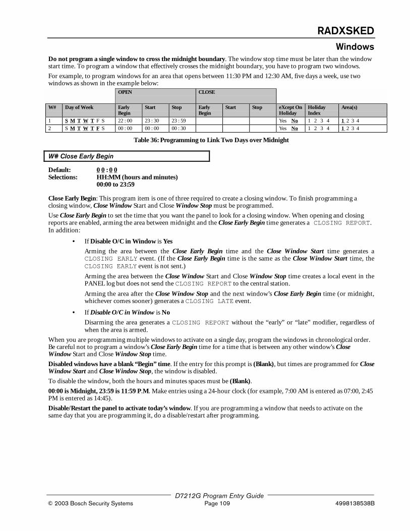
RADXSKEDWindows
D7212G Program Entry Guide © 2003 Bosch Security Systems Page 109 4998138538B
Do not program a single window to cross the midnight boundary. The window stop time must be later than the windowstart time. To program a window that effectively crosses the midnight boundary, you have to program two windows.
For example, to program windows for an area that opens between 11:30 PM and 12:30 AM, five days a week, use twowindows as shown in the example below:
OPEN CLOSE
W# Day of Week EarlyBegin
Start Stop EarlyBegin
Start Stop eXcept OnHoliday
HolidayIndex
Area(s)
1 S M T W T F S 22 : 00 23 : 30 23 : 59 Yes No 1 2 3 4 1 2 3 4
2 S M T W T F S 00 : 00 00 : 00 00 : 30 Yes No 1 2 3 4 1 2 3 4
Table 36: Programming to Link Two Days over Midnight
W# Close Early Begin
Default: 0 0 : 0 0Selections: HH:MM (hours and minutes)
00:00 to 23:59
Close Early Begin: This program item is one of three required to create a closing window. To finish programming aclosing window, Close Window Start and Close Window Stop must be programmed.
Use Close Early Begin to set the time that you want the panel to look for a closing window. When opening and closingreports are enabled, arming the area between midnight and the Close Early Begin time generates a CLOSING REPORT.In addition:
• If Disable O/C in Window is Yes
Arming the area between the Close Early Begin time and the Close Window Start time generates aCLOSING EARLY event. (If the Close Early Begin time is the same as the Close Window Start time, theCLOSING EARLY event is not sent.)
Arming the area between the Close Window Start and Close Window Stop time creates a local event in thePANEL log but does not send the CLOSING REPORT to the central station.
Arming the area after the Close Window Stop and the next window’s Close Early Begin time (or midnight,whichever comes sooner) generates a CLOSING LATE event.
• If Disable O/C in Window is No
Disarming the area generates a CLOSING REPORT without the “early” or “late” modifier, regardless ofwhen the area is armed.
When you are programming multiple windows to activate on a single day, program the windows in chronological order.Be careful not to program a window’s Close Early Begin time for a time that is between any other window’s CloseWindow Start and Close Window Stop time.
Disabled windows have a blank “Begin” time. If the entry for this prompt is (Blank), but times are programmed for CloseWindow Start and Close Window Stop, the window is disabled.
To disable the window, both the hours and minutes spaces must be (Blank).
00:00 is Midnight, 23:59 is 11:59 P.M. Make entries using a 24-hour clock (for example, 7:00 AM is entered as 07:00, 2:45PM is entered as 14:45).
Disable/Restart the panel to activate today’s window. If you are programming a window that needs to activate on thesame day that you are programming it, do a disable/restart after programming.

RADXSKEDWindows
D7212G Program Entry Guide 4998138538B Page 110 © 2003 Bosch Security Systems
W# Close Window Start
Default: 0 0 : 0 0Selections: HH:MM (hours and minutes)
Enter the time that you want the panel to start the closing window. The window goes into effect at the beginning of theminute.
00:00 is Midnight, 23:59 is 11:59 P.M. Make entries using a 24-hour clock (for example, 7:00 AM is entered as 07:00, 2:45PM is entered as 14:45).
This program item is one of three required to create a closing window. To program a closing window, Close Early Beginand Close Window Stop must also be programmed.
If the area is not armed when the Close Window Start time comes, a warning tone sounds and [PLEASE CLOSE NOW]displays at the command center. To temporarily silence the tone, press the [ESC] key on the command center. Thewarning tone restarts in 10 minutes if the area is not armed.
See Close Early Begin for report feature explanations.
W# Close Window Stop
Default: 0 0 : 0 0Selections: HH:MM (hours and minutes)
Enter the time that you want the panel to end the closing window. The window stops at the end of the minute.
00:00 is Midnight, 23:59 is 11:59 P.M. Make entries using a 24-hour clock (for example, 7:00 AM is entered as 07:00, 2:45PM is entered as 14:45).
This program item is one of three required to create a closing window. To program a closing window, Close Early Beginand Close Window Start must also be programmed.
If the area is not armed by the time the Close Window Stop time expires, the panel generates a FAIL TO CLOSEreport if enabled in Fail To Close.
Closing reports generated between the Close Window Start time and Close Window Stop time can be suppressed byprogramming Disable O/C in Window Yes. See Close Early Begin for other report feature explanations.
Do not use a time of 23:59 as a window-stop time unless the window continues on the next day at 00:00. FAIL TOCLOSE reports are not sent, and the Auto Close feature does not work for windows that stop at 23:59.
Do not program a single window to cross the midnight boundary. The window stop time must be later than the windowstart time. To program a window that effectively crosses the midnight boundary, you have to program two windows.
For example, to program windows for an area that closes between 11:30 PM and 12:30 AM, five days a week, use twowindows as shown:
OPEN CLOSE
W# Day of WeekEarlyBegin Start Stop
EarlyBegin Start Stop
eXcept OnHoliday
HolidayIndex Area(s)
1 S M T W T F S 22 : 00 23 : 30 23 : 59 Yes No 1 2 3 4 1 2 3 4
2 S M T W T F S 00 : 00 00 : 00 00 : 30 Yes No 1 2 3 4 1 2 3 4
Table 37: W# Close Window Stop Programming Example

RADXSKEDWindows
D7212G Program Entry Guide © 2003 Bosch Security Systems Page 111 4998138538B
W# Xept Holiday
Default: NoSelections: Yes or No
This entry allows you to determine if the window is disabled on holidays, or is active only on holidays.
To prevent the windows from activating on certain days of the year, program Xept Holiday Yes, and enable at least oneHoliday Index. When Xept Holiday is programmed Yes, the window executes on the days of the week programmed unlessthe date is designated as a Holiday by the Holiday Index(es) selected.
Yes Do not activate this window on holidays.To use this selection, the window must be programmed to activate on at least one day ofthe week and a Holiday Index must be enabled.
No A holiday will not prevent this window from activating.You also use this selection if opening and/or closing windows are only needed on certaindays of the year. Do not program the windows to execute on any days of the week. Instead,program Xept Holiday No, and select at least one Holiday Index with the days of the yearyou want the window to be active.
5.1.1.1 Holiday Indexes for O/C WindowsYou can enable up to four Holiday Indexes for use with Opening/Closing Windows. Enable at least one Holiday Index ifW# Xept Holiday is programmed Yes for this Window, or if you want this window to activate only on specific dates.Holidays are programmed in Section Holiday Indexes, beginning on page 123.
W# Holiday 1
Default: NoSelections: Yes or No
Yes Use Holiday Index 1 with this Window.
No Do not use Holiday Index 1 with this Window.
W# Holiday 2
Default: NoSelections: Yes or No
W# Holiday 3
Default: NoSelections: Yes or No
W# Holiday 4
Default: NoSelections: Yes or No
W# Area 1 [through 4]
Default: NoSelections: Yes or No
This item determines whether this window will activate in each of the available 4 areas.
Yes Activate the window in the area number (#) specified.
No Disable the window in the area number (#) specified.
Programming
Tip
010101010101
The D7212G allows up to only four areas. Although the D5200 allows entries for Areas 5 through 8, they arenot applicable for use on the D7212G.
If Areas 5 through 8 are inadvertently programmed on the D7212G, the command center will display CALLFOR SERVICE.

RADXSKEDWindows
D7212G Program Entry Guide 4998138538B Page 112 © 2003 Bosch Security Systems
5.1.1.2 Opening/Closing Windows WorksheetOPEN CLOSE
W# Day of WeekEarlyBegin Start Stop
EarlyBegin Start Stop
eXcept OnHoliday
HolidayIndex Area(s)
1 S M T W T F S _ _ : _ _ _ _ : _ _ _ _ : _ _ _ _ : _ _ _ _ : _ _ _ _ : _ _ Yes No 1 2 3 4 1 2 3 4
2 S M T W T F S _ _ : _ _ _ _ : _ _ _ _ : _ _ _ _ : _ _ _ _ : _ _ _ _ : _ _ Yes No 1 2 3 4 1 2 3 4
3 S M T W T F S _ _ : _ _ _ _ : _ _ _ _ : _ _ _ _ : _ _ _ _ : _ _ _ _ : _ _ Yes No 1 2 3 4 1 2 3 4
4 S M T W T F S _ _ : _ _ _ _ : _ _ _ _ : _ _ _ _ : _ _ _ _ : _ _ _ _ : _ _ Yes No 1 2 3 4 1 2 3 4
5 S M T W T F S _ _ : _ _ _ _ : _ _ _ _ : _ _ _ _ : _ _ _ _ : _ _ _ _ : _ _ Yes No 1 2 3 4 1 2 3 4
6 S M T W T F S _ _ : _ _ _ _ : _ _ _ _ : _ _ _ _ : _ _ _ _ : _ _ _ _ : _ _ Yes No 1 2 3 4 1 2 3 4
7 S M T W T F S _ _ : _ _ _ _ : _ _ _ _ : _ _ _ _ : _ _ _ _ : _ _ _ _ : _ _ Yes No 1 2 3 4 1 2 3 4
8 S M T W T F S _ _ : _ _ _ _ : _ _ _ _ : _ _ _ _ : _ _ _ _ : _ _ _ _ : _ _ Yes No 1 2 3 4 1 2 3 4
Table 38: Opening/Closing Windows Worksheet
Use this table to determine the proper entries for your application.
Day of Week
The column below briefly describes the ways toactivate an Opening/Closing Window.Use the guidelines shown in the other columns tochoose the appropriate entries.
eXcept OnHoliday Holiday Index Areas
Program at leastone day as Yes.
Day(s) of the Week No NoneProgram at leastone area as Yes.
Program at leastone day as Yes.
Day(s) of the Week, but NOT on Holidays YesSelect at leastone Index
Program at leastone area as Yes.
Program at leastone day as Yes.
Day(s) of the Week, PLUS Holidays NoSelect at leastone Index
Program at leastone area as Yes.
All days must beprogrammed No.
Only on Holidays NoSelect at leastone Index
Program at leastone area as Yes.
Table 39: Opening/Closing Windows
Normal Store Hours
Monday - Friday, Opening between 5-6 AM. Closing between 11 PM-1 AM.OPEN CLOSE
W# Day of Week EarlyBegin
Start Stop EarlyBegin
Start Stop eXcept OnHoliday
HolidayIndex
Area(s)
1 S M T W T F S 04: 00 05 : 00 06: 00 20: 00 23 : 00 23: 59 Yes No 1 2 3 4 1 2 3 4
2 S M T W T F S _ _ : _ _ _ _ : _ _ _ _ : _ _ 00: 00 00 : 00 01 : 00 Yes No 1 2 3 4 1 2 3 4
Delivery Schedule
Monday and Wednesday, In between 2:45-3:00 AM. Out between 3:15-3:30 AM.
Another alternative for delivery schedules would be to automatically bypass specific points using Skeds.OPEN CLOSE
W# Day of Week EarlyBegin
Start Stop EarlyBegin
Start Stop eXceptOnHoliday
HolidayIndex
Area(s)
3 S M T W T F S 02 : 30 02 : 45 03 : 00 03 : 05 03: 15 03: 30 Yes No 1 2 3 4 1 2 3 4
Program at least oneday as Yes.
Day(s) of the Week, but NOT on Holidays Yes Select atleast oneIndex
Program atleast one Areaas Yes.

RADXSKEDWindows
D7212G Program Entry Guide © 2003 Bosch Security Systems Page 113 4998138538B
Monthly Auditor’s Schedule
Sunday, In between 8-8:30 AM. Out between 2:30-5:00 PM.OPEN CLOSE
W# Day of Week EarlyBegin
Start Stop EarlyBegin
Start Stop eXcept OnHoliday
HolidayIndex
Area(s)
4 S M T W T F S 07 : 00 08 : 00 08 : 30 14 : 00 14: 30 17: 00 Yes No 1 2 3 4 1 2 3 4
All days must beprogrammed No.
Only On Holidays No Select atleast oneIndex
Program atleast oneArea as Yes.
5.1.2 User Group WindowsIn this section, you can create up to eight User Group periods in which the passcodes for the group chosen will beenabled. One user group can have multiple windows assigned to it within a 24-hour period. See U### User Group, inSection 3.1 Passcode Worksheet on page 91 to assign individuals to a group.
When you assign a U### User Group to one of the eight windows, all passcodes for the group will be enabled ONLY forthe period between the Enable Time and Disable Time for assigned User Window #.
If a user is not assigned to a U### User Group or the number programmed for the user for U### User Group is notassigned to a User Window #, the passcode for that user is enabled all the time.
User Windows #
Default: 1Selections: 1 – 8
Enter the User Window number you want to program.
UW# User Group
Default: 1Selections: (Blank), 1 – 8
Enter the number programmed for the group of users in the U### User Group prompt. This group will have their userpasscodes enabled/disabled when this window runs.
Programming
Tip
010101010101
A User Group can be assigned to more than one window in a 24-hour period, but the windows must notoverlap or exceed the midnight boundary.
UW# Sunday
Default: NoSelections: Yes or No
This prompt, and the next six “day of the week” prompts, select the days of the week that the User Group window isactive.
Programming
Tip
010101010101 See W# Sunday in O/C Windows instructions for more information about programming this prompt.
UW# Monday
Default: NoSelections: Yes or No

RADXSKEDWindows
D7212G Program Entry Guide 4998138538B Page 114 © 2003 Bosch Security Systems
UW# Tuesday
Default: NoSelections: Yes or No
UW# Wednesday
Default: NoSelections: Yes or No
UW# Thursday
Default: NoSelections: Yes or No
UW# Friday
Default: NoSelections: Yes or No
UW# Saturday
Default: NoSelections: Yes or No
UW# Group Enable
Default: 0 0 : 0 0Selections: HH:MM (hours and minutes)
This prompt must be programmed if this User Group Window is assigned to a user group.
Enter the time of day that the window starts. Beginning at this time, users assigned to this window’s group will be allowedto use their passcodes. The window goes into effect at the beginning of the minute. Make entries using a 24-hour clock(for example, 7:00 AM is entered as 07:00, 2:45 PM is entered as 14:45).
Disable/Restart the panel to activate today’s window. If you are programming a window that needs to activate on thesame day that you are programming it, do a disable/restart after programming.
UW# Group Disable
Default: 0 0 : 0 0Selections: HH:MM (hours and minutes)
This prompt must programmed if this User Group Window is assigned to a user group.
Enter the time of day that the window ends. This time marks the end of the period in which users assigned to thiswindow’s group will be able to use their passcodes. The window stops at the end of the minute. Make entries using a 24-hour clock (for example, 7:00 AM is entered as 07:00, 2:45 PM is entered as 14:45).
To disable the window, both the hours and minutes spaces must be (Blank).
Do not program a single window to cross the midnight boundary. The window stop time must be later than the windowstart time.

RADXSKEDSkeds
D7212G Program Entry Guide © 2003 Bosch Security Systems Page 115 4998138538B
5.1.2.1 Holiday Indexes for User Group WindowsYou can enable up to four Holiday Indexes to use with User Group Windows. Enable at least one Holiday Index if UW#Xept Holiday is programmed Yes for this User Window, or if you want this window to activate only on specific dates.Holidays are programmed in Section 5.3 Holiday Indexes on page 123.
UW# Xept Holiday
Default: NoSelections: Yes or No
This entry allows you to determine if the window is disabled on holidays, or is active only on holidays. Use theinstructions provided in W# Xept Holiday.
UW# Holiday 1
Default: NoSelections: Yes or No
UW# Holiday 2
Default: NoSelections: Yes or No
UW# Holiday 3
Default: NoSelections: Yes or No
UW# Holiday 4
Default: NoSelections: Yes or No
5.2 SkedsUse the SKEDS module to program the PANEL to automatically execute functions that are otherwise initiated by the enduser at the command center. Each Sked can be programmed to occur at a specific time on a specific date or day of theweek. Up to 40 Skeds can be programmed.
A Sked can be edited from the command center if S## Time Edit? is yes. The date and time can be changed using theChange Sked? function.
Each Sked Number can be programmed with one of sixteen functions for the S## Function Code. A function is what willbe executed. In addition to the function, a choice has to be made as to what will be affected by the function (e.g., whenchoosing a Disarm Sked, the disarming is the function while the areas that are being chosen to become disarmed are whatis affected).
The functions and their associated parameters are listed in the “Sked Function Code Table” in the Program Record Sheet,and they are explained in detail following the S## Function Code prompt.
Each Sked can be programmed with up to four Holiday Indexes. The Holiday Indexes can be used to execute the Sked onthe Holidays in addition to the Date or Day(s) of the Week, or, they can be used to prevent the Sked from executing onthe Holidays (see S## Xept Holiday).
Sked Number
Default: 1Selections: 1 – 40
Enter the number of the Sked you are programming.

RADXSKEDSkeds
D7212G Program Entry Guide 4998138538B Page 116 © 2003 Bosch Security Systems
S## TimeEdit
Default: YesSelections: Yes or No
Select whether the user can edit the time of this Sked from the command center.
Yes The user can edit the time of this Sked from the command center and it will appear in theCHG SKED display.
No The user cannot edit the time of this Sked from the command center and it will NOTappear in the CHG SKED displays.
S## Function Code
Default: (Blank)Selections: 1 – 11, 13 – 15, 28, 29
Enter the Function Code you want this Sked to execute. Sked Function 12 is reserved and is not a valid entry.
The programmer automatically displays the available parameter choices and range fields for this function. (e.g., Yes/Nois automatically displayed for the areas when choosing the arm/disarm function while a blank prompt exists for the pointnumber you want to bypass when choosing the bypass point function).
After you program the parameter choices associated with the Sked function, press EXIT GROUP to continueprogramming the Sked for date, day of week, time, and holiday.
1 Arm Area. This function simulates the MASTER ARM DELAY command center function. Entries inthe S## Area # prompts define the area(s) this Sked arms. The Sked can arm multiple areas. If anypoint is faulted when the Sked executes, it is force armed regardless of FA/Bypass max.
S## Area 1 [through 4]
Default: NoSelections: Yes or No
Enable the Sked to arm the areas indicated with Yes.
Yes Arm Area #
No Do not arm Area #
2 Disarm Area. This function emulates the [DISARM_ _ _] command center function. Entries in theS## Area # prompts define the area(s) this Sked disarms. The Sked can disarm multiple areas.
S## Area 1 [through 4]
Default: NoSelections: Yes or No
Enable the Sked to disarm the areas indicated with Yes.
Yes Disarm Area #
No Do not disarm Area #
Programming
Note
010101010101 Do not enable Areas 5 through 8 as they are not available with the D7212G.
3 Bypass a Point. This function emulates the Bypass Pt? Command center function. The entry in theS## Point Number prompt defines the point this Sked bypasses. The point can be bypassed only ifBypassable is programmed Yes in the Point Index assigned to the point. The bypass is reported ifBypass Reports are enabled in the Point Index assigned to the point. The Sked can bypass one point.
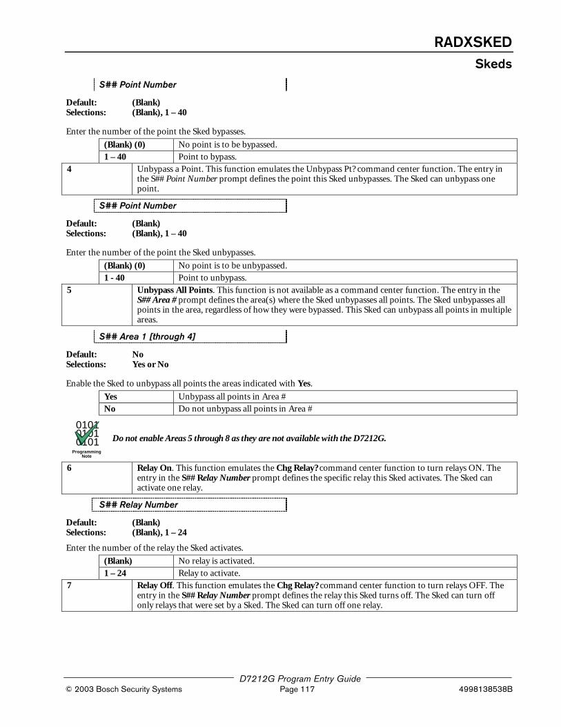
RADXSKEDSkeds
D7212G Program Entry Guide © 2003 Bosch Security Systems Page 117 4998138538B
S## Point Number
Default: (Blank)Selections: (Blank), 1 – 40
Enter the number of the point the Sked bypasses.
(Blank) (0) No point is to be bypassed.
1 – 40 Point to bypass.
4 Unbypass a Point. This function emulates the Unbypass Pt? command center function. The entry inthe S## Point Number prompt defines the point this Sked unbypasses. The Sked can unbypass onepoint.
S## Point Number
Default: (Blank)Selections: (Blank), 1 – 40
Enter the number of the point the Sked unbypasses.
(Blank) (0) No point is to be unbypassed.
1 - 40 Point to unbypass.
5 Unbypass All Points. This function is not available as a command center function. The entry in theS## Area # prompt defines the area(s) where the Sked unbypasses all points. The Sked unbypasses allpoints in the area, regardless of how they were bypassed. This Sked can unbypass all points in multipleareas.
S## Area 1 [through 4]
Default: NoSelections: Yes or No
Enable the Sked to unbypass all points the areas indicated with Yes.
Yes Unbypass all points in Area #
No Do not unbypass all points in Area #
Programming
Note
010101010101 Do not enable Areas 5 through 8 as they are not available with the D7212G.
6 Relay On. This function emulates the Chg Relay? command center function to turn relays ON. Theentry in the S## Relay Number prompt defines the specific relay this Sked activates. The Sked canactivate one relay.
S## Relay Number
Default: (Blank)Selections: (Blank), 1 – 24
Enter the number of the relay the Sked activates.
(Blank) No relay is activated.
1 – 24 Relay to activate.
7 Relay Off. This function emulates the Chg Relay? command center function to turn relays OFF. Theentry in the S## Relay Number prompt defines the relay this Sked turns off. The Sked can turn offonly relays that were set by a Sked. The Sked can turn off one relay.

RADXSKEDSkeds
D7212G Program Entry Guide 4998138538B Page 118 © 2003 Bosch Security Systems
S## Relay Number
Default: (Blank)Selections: (Blank), 1 – 24
Enter the number of the relay the Sked turns off.
(Blank) No relay is turned off.
1 – 24 Relay to turn off.
8 All Relays Off. This function is not available as a command center function. This Sked function turnsoff all relays that were turned on by a Sked. This is a panel wide function.There are no other parameters that require input for this option.
9 Test Report. This function emulates the Send Report? command center function. This functiongenerates a test report ONLY from Area 1 but contains panel wide status information. The report issent to the Phone(s) programmed for Test and Status Reports in Phone Routing.If Expand Test Prt in Phone is programmed Yes, the test report also includes all off-normal states forevents listed in Diagnostic Reports and Test Reports (see Section 2.3 Routing on page 16).The test report can be deferred if any other report was sent since the last test report. To defer the testreport, program S## Defer Test.The test report can be sent every hour beginning at the time scheduled in S## Time. To send a testreport every hour, program S## Hourly Rpt.
S## Defer Test
Default: NoSelections: Yes or No
Enable Sked to defer the test report.
Yes Defer the test report.
No Send the test report on schedule.
S## Hourly Rpt
Default: NoSelections: Yes or No
Enable Sked to send the test report every hour.
Yes Send the test report every hour.
No Send the test report only as scheduled.
10 Status Report. This function generates a status report for each area that is enabled. The report is sentto the Phone(s) programmed for Test and Status Reports in Phone Routing.The status report can be deferred if any other report was sent since the last status report. To defer thestatus report, program S## Defer Status.
S## Defer Status
Default: NoSelections: Yes or No
Enable Sked to defer the status report.
Yes Defer the status report.
No Send the status report on schedule.
11 Execute Custom Func. This function emulates any of the custom functions assigned to thecommand center that can be executed by a user from the command center. When a Skedexecutes a Custom Function, it is subject to the scope of the selected command center. CmdCenter and Custom Func prompts appear after entering function code 11. Both entries arerequired.Caution: Avoid having multiple functions occur at the same time at the same address. Functionscan clash and the effect on the panel is unpredictable.

RADXSKEDSkeds
D7212G Program Entry Guide © 2003 Bosch Security Systems Page 119 4998138538B
010101010101
Review to make sure that the Custom Function being executed or any of the commands nested inside theCustom Function are not passcode protected.
Programming
Tip
010101010101
Do not program multiple Skeds to execute at the same command center during the same time of execution.
Do not program Skeds to execute at times when a user is likely to be executing functions at the commandcenter. If it is necessary to do so, there are two ways to work around the situation:
1. Program “CC” at the beginning of the Custom Function Key Strokes entry. This will abort the user’sfunction and allow the Sked to execute.
2. Program the Sked to execute at an address (Cmd Center) that has no command center physically attachedto it. The CC # must be assigned to an area and have the appropriate Scope programmed.
S## Cmd Center
Default: (Blank) (0)Selections: (Blank) (0), 1 – 8
Identify the specific Keypad (CC #) where the Custom Function is entered. Only one command center can be assignedfor this Sked function.
(Blank) (0) No command center is specified for Custom Function activation.
1 – 8 command center address specified for Custom Function activation.
S## Custom Func
Default: (Blank) (0)Selections: (Blank) (0) 128 – 131
Enter the Custom Function this Sked executes.
(Blank) (0) No Custom Function will be activated.
128 – 131 Custom Function to be activated.
13 Adjust Time Forward One Hour. This Sked function is used to make adjustments to the panel’sclock. A typical application is to program this to go into effect at 2:00 AM on the date thatDaylight Savings Time begins (during the springtime). No TIME CHANGE report is sent orlogged, but the new time appears in the next report logged.There are no other parameters that require input for this option.
14 Adjust Time Backward One Hour. This Sked function is used to make adjustments to thepanel’s clock. A typical application is to program this to go into effect at 2:00 AM on the datethat Daylight Savings Time ends (during the fall). This function can operate only once in a day,even if multiple Skeds with this function are programmed. No TIME CHANGE report is sent orlogged, but the new time appears in the next report logged.There are no other parameters that require input for this option.
15 Sound Watch Tone at Command Center. This function sounds the Watch Tone at thecommand center address programmed in Parameter 1. The Watch Tone sounds at all commandcenters with the address programmed. Press [ESC] to silence the tone.Sound Watch Tone defines the command center address where the Watch Tone sounds. Enterthe specific address at the S## Cmd Center prompt.

RADXSKEDSkeds
D7212G Program Entry Guide 4998138538B Page 120 © 2003 Bosch Security Systems
S## Cmd Center 1 [through 8]
Default: (Blank)Selections: (Blank), Yes or No
Enable the Sked to beep the command center programmed Yes.
Yes Watch tone will sound at this command center.
No Watch tone will not sound at this command center.
RAM IV version 3.6 or higher and RADXSKED handler version 1.02 or higher must be used to program thesenew Skeds.
28 Expanded Off-Normal Test Report. In order to generate this event, one or more points must bein an off-normal state at the time the Sked executes. In addition to this, any System Trouble thatis active also generates an Expanded Off-Normal Test Report. Expanded Off-Normal TestReports include the Off Normal Test Report event as well as the supplementary event at the timethe report is generated.However, the Event Log only shows a Test Report event.If none of these conditions exist at the time the Sked executes, only a Sked Executed event isgenerated and the Off-Normal Test Report is not sent.
To meet UL 985 daily test report requirements (when using two phone lines) you must still use Sked FunctionCode 9, Test Report and program it to occur on a daily basis as per AHJ requirements.
29 Non-Expanded Off-Normal Test Report. Non-Expanded Off-Normal Test Report events areonly sent when any point is in the off-normal state from any area but only sends the Off NormalTest Report event. In addition to this, any System Trouble that is active also generates a Non-Expanded Off-Normal Test Report.However, the Event Log only shows a Test Report event.If none of these conditions exist at the time the Sked executes, only a Sked Executed eventis generated and the Non-Expanded Off-Normal Test Report is not sent.
S## Time
Default: 0 0 : 0 0Selections: HH:MM (hours and minutes)
Enter the time that the Sked executes. Make entries using a 24-hour clock (for example, 7:00 AM is entered as 07:00, 2:45PM is entered as 14:45).
Disabled Skeds have a (Blank) time. If you copy the panel and the entry for this prompt is blank, but times were at onetime programmed, the Sked may have been disabled from the command center using the CHANGE SKEDS function.
To program a time:1. Press the two digits representing the hour.2. The cursor advances past the colon (:) in the display.3. Press the two digits representing the minutes.4. Press [ENT].

RADXSKEDSkeds
D7212G Program Entry Guide © 2003 Bosch Security Systems Page 121 4998138538B
S## Date
Default: __ __ / __ __Selections: MM/DD (month and date)
Enter the date that the Sked executes.
Disabled Skeds have a (Blank) date. If you copy the panel and the entry for this prompt is blank, but dates were at onetime programmed, the Sked may have been disabled from the command center using the CHANGE SKEDS function.
To program a date:5. Press the two digits representing the hour.6. The cursor advances past the colon (:) in the display.7. Press the two digits representing the minutes.8. Press [ENT].
S## Sunday
Default: NoSelections: Yes or No
This prompt, and the next six prompts, selects the days of the week that the Sked is active.
Exceptions:
To prevent the Sked from activating on certain days of the year, program Xept Holiday Yes, and enable at least oneHoliday Index. When Xept Holiday is programmed Yes, the window executes on the days of the week programmed unlessthe date is designated as a Holiday by the Holiday Index selected.
If a Sked is only needed on certain days of the year, do not program the Sked to execute on any days of the week. Instead,program Xept Holiday No, and select a Holiday Index with the dates you want the window to be active.
Yes Activate this Sked on Sundays.
No Do not activate this Sked on Sundays.
S## Monday
Default: NoSelections: Yes or No
S## Tuesday
Default: NoSelections: Yes or No
S## Wednesday
Default: NoSelections: Yes or No
S## Thursday
Default: NoSelections: Yes or No
S## Friday
Default: NoSelections: Yes or No

RADXSKEDSkeds
D7212G Program Entry Guide 4998138538B Page 122 © 2003 Bosch Security Systems
S## Saturday
Default: NoSelections: Yes or No
S## Xept Holiday
Default: NoSelections: Yes or No
Yes Prevent this Sked from operating on the Holidays identified in the specific HolidayIndex(es) used with this Sked. Specific Holiday Indexes are selected in this programmingsection and programmed in the next programming module.
No This Sked operates on Holidays programmed in the Holiday Index(es) used with this Sked.
If no Days of the Week are programmed, this Sked operates only on the Holidays programmed in the Holiday Index(es)used with this Sked. This Sked also operates if the Holiday falls on a day of the week that is programmed.
S## Holiday 1
Default: NoSelections: Yes or No
Yes Use Holiday Index 1 with this Sked.
No Do not use Holiday Index 1 with this Sked.
S## Holiday 2
Default: NoSelections: Yes or No
S## Holiday 3
Default: NoSelections: Yes or No
S## Holiday 4
Default: NoSelections: Yes or No
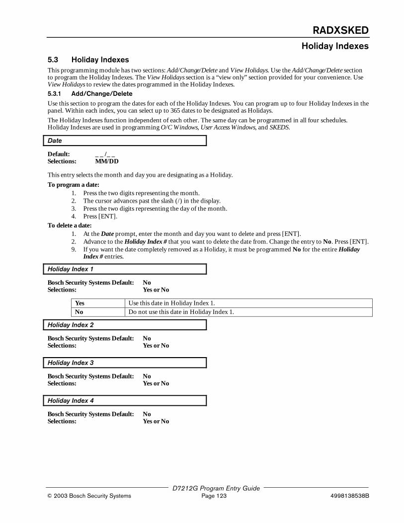
RADXSKEDHoliday Indexes
D7212G Program Entry Guide © 2003 Bosch Security Systems Page 123 4998138538B
5.3 Holiday IndexesThis programming module has two sections: Add/Change/Delete and View Holidays. Use the Add/Change/Delete sectionto program the Holiday Indexes. The View Holidays section is a “view only” section provided for your convenience. UseView Holidays to review the dates programmed in the Holiday Indexes.
5.3.1 Add/Change/DeleteUse this section to program the dates for each of the Holiday Indexes. You can program up to four Holiday Indexes in thepanel. Within each index, you can select up to 365 dates to be designated as Holidays.
The Holiday Indexes function independent of each other. The same day can be programmed in all four schedules.Holiday Indexes are used in programming O/C Windows, User Access Windows, and SKEDS.
Date
Default: _ _ /_ _Selections: MM/DD
This entry selects the month and day you are designating as a Holiday.
To program a date:1. Press the two digits representing the month.2. The cursor advances past the slash (/) in the display.3. Press the two digits representing the day of the month.4. Press [ENT].
To delete a date:1. At the Date prompt, enter the month and day you want to delete and press [ENT].2. Advance to the Holiday Index # that you want to delete the date from. Change the entry to No. Press [ENT].9. If you want the date completely removed as a Holiday, it must be programmed No for the entire Holiday
Index # entries.
Holiday Index 1
Bosch Security Systems Default: NoSelections: Yes or No
Yes Use this date in Holiday Index 1.
No Do not use this date in Holiday Index 1.
Holiday Index 2
Bosch Security Systems Default: NoSelections: Yes or No
Holiday Index 3
Bosch Security Systems Default: NoSelections: Yes or No
Holiday Index 4
Bosch Security Systems Default: NoSelections: Yes or No

RADXSKEDHoliday Indexes
D7212G Program Entry Guide 4998138538B Page 124 © 2003 Bosch Security Systems
5.3.2 View HolidaysThe View Holidays section is a “view only” section provided for your convenience. Use View Holidays to review the datesyou have programmed into each of the Holiday Indexes.
You can view the first 100 dates programmed in each of the indexes.
Index 1 Days
Default: (Blank)Selections: ENTER GROUP or Down Arrow
Press ENTER GROUP to view the dates programmed in Holiday Index 1.
Press [�] (Down Arrow Key) to advance to the next Holiday Index.
Index 2 Days
Default: (Blank)Selections: ENTER GROUP or Down Arrow
Index 3 Days
Default: (Blank)Selections: ENTER GROUP or Down Arrow
Index 4 Days
Default: (Blank)Selections: ENTER GROUP or Down Arrow

RADXAUX1SDI Automation
D7212G Program Entry Guide © 2003 Bosch Security Systems Page 125 4998138538B
6.0 RADXAUX16.1 IntroductionThe RADXAUX1 Handler is a handler for the D7212G panel that is primarily used for programming EnhancedCommunication capabilities.
The RADXAUX1 Handler currently has six sections: SDI Automation, SDI RAM Parameters, EnhancedCommunications, SDI RAM / Enhanced Communication Configuration, Miscellaneous, and Cross Point Parameters. Asnew features (that require new programmable prompts) are added, they will most likely be added to a new revision of thishandler. To add the RADXAUX1 Handler to your D5200 Programmer, call the Bosch Systems Handler Update System at(800) 657-4584.
The term Enhanced Communications is used to represent the ability to provide new communication functions for thepanels via the SDI Bus including the ability to:
• Route panel events to a D9133TTL-E module.
• Communicate with RAM IV using a D9133TTL-E module.
• Communicate with a remote or local head-end software package.
6.2 SDI AutomationThis section allows you to define the characteristics of the D9133 Serial Interface Module when used with Home orBusiness Automation software. The D9133 Serial Interface Module is a bi-directional SDI to RS232 interface module thatallows the panels to send/receive information to/from an external software program. This Automation protocol will allowexternal software programs to interact and perform functions; such as, arming and disarming areas, changing userpasscodes and names, and turning relays on and off. The following items allow some simple configuration options;however, to receive the D9133 Automation protocol you must contact Bosch Security Systems Technical SupportMonday through Friday 5 AM to 5 PM Pacific Time at (888) 886-6189.
Enable SDI Auto
Default: NoSelections: Yes or No
Turning this item to Yes enables the automation address (SDI Address 80).
Yes Enable Automation software.
No Disable Automation software
Baud Rate
Default: 9600Selections: 300, 1200, 2400, 4800, 9600, 14.4K
This item determines the baud rate between the D9133 and the external hardware connected to it. Since the SDI buscommunicates at 9600 baud, Bosch Security Systems recommends that this prompt also be kept at 9600 baud. Pressingthe [SPACE] bar on the D5200 toggles through the available options.

RADXAUX1SDI Automation
D7212G Program Entry Guide 4998138538B Page 126 © 2003 Bosch Security Systems
Parity / Stop
Default: No / 1Selections: No / 1, No / 2, Odd / 1, Even / 1
This prompt addresses two items; Parity and the number of Stop Bits. Pressing the [SPACE] bar on the D5200 togglesthrough the available options.
No / 1 No Parity, 1 Stop Bit.
No / 2 No Parity, 2 Stop Bits.
Odd / 1 Odd Parity, 1 Stop Bit.
Even / 1 Even Parity, 1 Stop Bit.
Table 40: SDI Automation Parity and Stop Bits
D9133 Supervision
Default: NoSelections: Yes or No
This item determines whether the D9133 Serial Interface Module is supervised or not. If the D9133 is supervised,disconnecting the D9133 from the panel will create a TROUBLE SDI 80 event and the command center will annunciate atrouble tone (if programmed) and display SERVC SDI 80.
Note: TROUBLE SDI 80 reports are always reported using Area 1’s Account number.
Yes Supervise the D9133 Serial Interface Module.
No Do not supervise the D9133 Serial Interface Module.
RTS Control
Default: OnSelections: On, AutoX, Off, AutoR
This item determines how the Request To Send Control parameters are defined for the D9133. Pressing the [SPACE] baron the D5200 toggles through the available options.
On Sets RTS to on (hardware control).
AutoX Automatically enables Xon/Xoff (software control).
Off Sets RTS off (hardware control).
AutoR Sets this to Auto RTS.
Table 41: SDI Automation RTS Controls
DTR Control
Default: OnSelections: On, AutoD, Off
This item determines how the Data Terminal Ready Control parameters are defined for the D9133. Pressing the [SPACE ]bar on the D5200 toggles through the available options.
On Sets DTR to on (hardware control).
AutoD Sets this to Auto DTR.
Off Sets DTR off (hardware control).
Table 42: SDI Automation DTR Controls

RADXAUX1SDI Automation
D7212G Program Entry Guide © 2003 Bosch Security Systems Page 127 4998138538B
Status Rate
Default: 0Selections: 0 – 255
This item determines how often the default status information is sent to the D9133 Serial Interface Module. The Statusinformation includes:
• the current point status (normal or off-normal),
• the panel’s area status (Master Armed, Master Instant Armed, Perimeter Delay Armed, Perimeter InstantArmed, Disarmed, Area Entry Delay, Perimeter Entry Delay, Area Exit Delay, Perimeter Exit Delay),
• the panel status (AC fail, battery missing, AC restore, battery low, etc.), and
• relay status (relay on or relay off).
Entries are in 100 millisecond increments. Therefore, if a 5 is entered, the Status information is sent every 500milliseconds (or ½ second). An entry of 10 would equal 1 second.
0 Status information never sent unless requested.
1 – 255* Status information is sent at the interval programmed.
* Note: If the Status Rate is set to a value under 10 and there are 1 – 6 SDI devices connected to the system, the fastest thepanel can send the Status information is approximately 1 second. In addition to this, if there are more than 6 SDIDevices connected to the panel, the fastest the panel can send the information is approximately 1½ to 2 seconds.

RADXAUX1SDI RAM Parameters
D7212G Program Entry Guide 4998138538B Page 128 © 2003 Bosch Security Systems
6.3 SDI RAM ParametersThis section allows you to configure Remote Account Manager (RAM) parameters when communicating locally with aPC, over a Local Area Network (LAN), a Wide Area Network (WAN), or the Internet. To use RAMIV locally, a DirectConnect Programming Module (D9133DC) is required. To use RAMIV over a LAN/WAN/Internet, an SDI-EthernetModule (D9133TTL-E) is required and the PC RAMIV is installed on must have a network card. See your InformationSystems’ administrator for network requirements.
In addition to this, this section allows you to
• define the RAM parameters necessary to communicate via an external modem that can be connected to aD9133DC Direct Connect Programming Module or
• provide for local programming via a D9133 Serial Interface Module.
Although it is not listed in this section, RAM IV still checks for the RAM Passcode (see RAM Parameters), Datalock Codeand the panel type to determine if this RAM session should continue.
6.3.1 User Interface Modifications for CMD 43CMD 43 has been modified to compensate for now being able to communicate with RAM IV via a network path. Refer toFigure 3 for CMD 43’s structure.
COMM AND 43
CONTACT RAM?
ANSWER NOW?
PREVkey
NEXTkey
RAM VIA PHONE?
RAM VIA NETWORK?
PREVkey NEXT
key
ENTkey
Seizes Phone Lineand calls RAM IV
Begins RAM IVsession over thenetwork
ENTkey
ENTkey
Seizes Phone Lineand begins RAM IVsession
Figure 3: CMD 43 Flowchart
Pressing the [ESC] key while CONTACT RAM?, ANSWER NOW?, RAM VIA PHONE?, or RAM VIA NETWORK? isdisplaying will exit the user to Idle Text.
Note: The RAM VIA PHONE? prompt shown above, if selected, will contact RAM via the panel phone line and not theexternal modem. Users will not be able to initiate a RAM session via the external modem. If you are using anexternal modem, RAM sessions can only be initiated by programming Answer Armed and Answer Disarmed (toa value greater than 0) in Section 6.3 SDI RAM Parameters on page 128.
Enable SDI RAM
Default: YesSelections: Yes or No
This item determines if the panel will allow RAM IV communications over the SDI bus. This item must be set to Yes ifyou plan on using the External Modem configuration, a LAN/WAN/Internet connection, or local RAM IV programming.
Yes Enable RAM sessions over the SDI bus.
No Do not enable RAM sessions over the SDI bus.
Note: If the reset pin is in the locked position, local RAM IV programming is still allowed even if this prompt is set to No.
Application
Tip
When configuring this item to allow for local programming, remember that the D9133DC must have Jumper8 shorted, the power must be cycled after changing the address, and a serial cable is required.

RADAUX1SDI RAM Parameters
D7212G Program Entry Guide © 2003 Bosch Security Systems Page 129 4998138538B
Call Back Enabled
Default: NoSelections: Yes or No
Using this function allows the panel, after it has verified the RAM passcode, to provide an additional level of security byending the SDI RAM session and then reconnecting with RAM using
a) The RAM IP Address (Enable Ext Modem must be set to No) orb) The RAM Dial String (Enable Ext Modem must be set to Yes)
before allowing any upload or download.
Yes When the panel hears the proper RAM password (see RAM Passcode in RAM Parameters)it ends the SDI RAM session and then attempts to reconnect to RAM using the RAM IPAddress if Enable Ext Modem is set to No. If Enable Ext Modem is set to Yes, the panel willattempt to re-establish communication with RAM using the RAM Dial String. Thisensures that the panel only communicates with valid RAM units.
No The SDI RAM session is initiated immediately; no ‘call back’ is required. The panel canengage in SDI RAM sessions regardless of originating location.
RAM IP Address 1
Default: 0Selections: 0 – 255
This prompt and the next three prompts will determine the IP address for RAM IV.
An IP Address consists of four fields. Each field has a range of 0 – 255. As an example, an IP Address is expressed as110.227.64.190. The D5200 programmer has split the IP Address into four programmable fields. Be sure you contact yournetwork administrator to find out the IP Address to which the RAM IV computer is connected.
110.227.64.190
RAM IP Address 1
RAM IP Address 2
RAM IP Address 3
RAM IP Address 4
Figure 4: RAM IP Address Prompts
Note: Set this item to 0 if Enable Ext Modem is set to Yes.
0 – 255 Enter the first three digits of the IP Address. if the field is one or two digits in length,leading zeros are not required.
RAM IP Address 2
Default: 0Selections: 0 – 255
See RAM IP Address 1.

RADXAUX1SDI RAM Parameters
D7212G Program Entry Guide 4998138538B Page 130 © 2003 Bosch Security Systems
RAM IP Address 3
Default: 0Selections: 0 – 255
See RAM IP Address 1.
RAM IP Address 4
Default: 0Selections: 0 – 255
See RAM IP Address 1.
6.3.2 Using an external modemThrough the use of a standard, off-the-shelf modem (capable of communicating at 9600-baud) and a D9133DCconnected directly to the panel, RAM IV can communicate with a D7212G panel at speeds of up to 9600 baud.
Both the U.S.Robotics V.92 56K Modem (model # 5686, includes V.92 and V.90 56K standard technology)and the Best Data Smart One V.92/V.44 56K External Data/Fax Modem (model # 56SX-92) arerecommended for use as external modems (connected to the panel) based on compatibility testing by BoschSecurity Systems.
The following seven prompts help configure the requirements necessary to allow an external modem to be connected to aD7212G panel via a D9133DC. Configuring the system in this fashion now allows you to communicate with RAM IV at9600 baud because communication is being routed through the SDI Bus.
Note 1: Bosch Security Systems strongly recommends that a separate phone line be used if an external modem is going tobe connected to the panel via a D9133DC Direct Connect Programming Module. However, if it is not possible to obtain adifferent phone line than the panel is using, be absolutely sure that the panel is still wired in front of any premises phoneand the external modem devices so that full line seizure is still maintained. In addition to this, you will want to make surethat the following items are programmed in Section 2.7 RAM Parameters on page 34 in the 9000MAIN/RAM Parametershandler as shown below:
Answer Armed = (Blank) or 0
Answer Disarmed = (Blank) or 0
RAM Line Monitor = No
RAM Call Back = No
RAM Phone # = (Blank)
Note 2: When using an external modem, it must be pre-initialized to the following parameters using HyperTerminal onyour computer. Please note that the HyperTerminal procedures may vary depending upon the Operating Systemused.
1. In Windows®, open the HyperTerminal application within Programs, Accessories, Communications.
2. Connect the modem to an available Com Port.
3. Once connected, select the appropriate Com Port within HyperTerminal. See Figure 5 on page 131.

RADAUX1SDI RAM Parameters
D7212G Program Entry Guide © 2003 Bosch Security Systems Page 131 4998138538B
Figure 5: Com Port Selection within HyperTerminal
4. For Best Data Smart One V.92, type ATS37 = 9 [ENT]. For US Robotics, type AT&N6 [ENT]. This will setthe Baud rate of the modem to 9600. For modems other than US Robotics or Best Data Smart One V.92,please consult your individual modem’s instructions for the correct text string.
5. Type ATE0 [ENT]. This will eliminate echo, making all user input from this point forward invisible onscreen.
6. Type AT&W0 [ENT]. This writes the configuration to modem memory. This will save the modem profileto a file and upon disconnection or power loss.
If you are going to use an External Modem for RAM IV communications, Enhanced Communications andRAM IV functions using a D9133TTL-E are disabled.
The external modem is connected to the D9133DC Direct Connect Programming Module, which in turn, is connected tothe SDI Bus using SDI Address 88, see Figure 6. A standard serial cable is required to connect the D9133DC to theexternal modem.
Figure 6: External Modem Connection

RADXAUX1SDI RAM Parameters
D7212G Program Entry Guide 4998138538B Page 132 © 2003 Bosch Security Systems
Note 3: In order to use an off-the-shelf external modem and a D9133DC serial module to connect to the panel via RAM,the following settings must be used:
1. RADXAUX1\ENHANCED COMM\Enhanced Comm\No
2. RADXAUX1\SDI RAM PARAMETERS\Enable SDI RAM\Yes
3. RADXAUX1\SDI RAM PARAMETERS\Callback Enabled\No
4. RADXAUX1\SDI RAM PARAMETERS\RAM IP Address 1-4\0
5. RADXAUX1\SDI RAM PARAMETERS\Enable Ext Modem\Yes
6. RADXAUX1\SDI RAM PARAMETERS\Answer Armed\1 to 15
7. RADXAUX1\SDI RAM PARAMETERS\Answer Disarmed\1 to 15
8. RADXAUX1\SDI RAM PARAMETERS\RAM Line Monitor\No
9. RADXAUX1\SDI RAM PARAMETERS\Seize Relay\No
10. RADXAUX1\SDI RAM PARAMETERS\Modem Init String\ATE0
11. RADXAUX1\SDI RAM PARAMETERS\RAM Dial String\ (Blank)
12. RADXAUX1\SDIRAM/ENHANCED CONF\Baud Rate\9600
13. RADXAUX1\SDIRAM/ENHANCED CONF\Parity/Stop No\1
14. RADXAUX1\SDIRAM/ENHANCED CONF\RTS Control\ON
15. RADXAUX1\SDIRAM/ENHANCED CONF\DTR Control\ON
16. RADXAUX1\SDIRAM/ENHANCED CONF\9133 Supervision\No
17. 9000MAIN\PANEL WIDE PARAMETER\Enhanced Routing\RG1 Primary SDI\No
18. 9000MAIN\PANEL WIDE PARAMETER\Enhanced Routing\RG1 Backup SDI\No
19. 9000MAIN\PANEL WIDE PARAMETER\Enhanced Routing\RG2 Primary SDI\No
20. 9000MAIN\PANEL WIDE PARAMETER\Enhanced Routing\RG2 Backup SDI\No
21. 9000MAIN\PANEL WIDE PARAMETER\Enhanced Routing\RG3 Primary SDI\No
22. 9000MAIN\PANEL WIDE PARAMETER\Enhanced Routing\RG3 Backup SDI\No
23. 9000MAIN\PANEL WIDE PARAMETER\Enhanced Routing\RG4 Primary SDI\No
24. 9000MAIN\PANEL WIDE PARAMETER\Enhanced Routing\RG4 Backup SDI\No
25. The panel reset pin can be up or down.
26. The modem at the panel location must be set for 9600 baud and echo off. Then this info must be written tothe modem configuration area. Hyperterminal can be used to send the following Hayes modem commands:(note: refer to the modem manual regarding command syntax)
27. ATS37=9 (set baud rate to 9600)
28. ATE0 (eliminate echo)
29. AT&W0 (write configuration to modem memory) (not echoed)
30. Ensure the modem at RAM4 is setup for 9600 baud.
31. From the panel communication window on RAM, connect via modem at 9600 baud.

RADAUX1SDI RAM Parameters
D7212G Program Entry Guide © 2003 Bosch Security Systems Page 133 4998138538B
Enable Ext Modem
Default: NoSelections: Yes or No
Setting this item to Yes instructs the control/communicator that SDI Address 88 is enabled for use with an ExternalModem. For further information on Local RAM IV programming, please refer to the RAM IV Operation Manual (P/N:38849).
Note: Setting this item to Yes disables Enhanced Communication and SDI RAM for use over a Local or Wide AreaNetwork.
Yes Enable SDI Address 88 for use with an External Modem.
No Disable SDI Address 88 for use with an External Modem.
Answer Armed
Default: 7Selections: 0 – 15
This item determines the number of rings after which the External Modem will automatically answer a call if all areas areMaster Armed.
0 No answer when all areas are Master Armed.
1-15 The panel answers the phone after the specified number of rings when all areas are MasterArmed.
Answer Disarmed
Default: 7Selections: 0 – 15
This item determines the number of rings after which the External Modem will automatically answer a call if any area isPerimeter Armed or Disarmed.
0 No answer when any area is Perimeter Armed or Disarmed.
0-15 The panel answers the phone after the specified number of rings when any area isPerimeter Armed or Disarmed.
RAM Line Monitor
Default: NoSelections: Yes or No
This item is not yet implemented. Keep this item set to No.
Seize Relay
Default: NoSelections: Yes or No
This item is not yet implemented. Keep this item set to No.

RADXAUX1SDI RAM Parameters
D7212G Program Entry Guide 4998138538B Page 134 © 2003 Bosch Security Systems
Modem Init String
Default: ATE0Selections: A – Z (caps only), 0 – 9, (SPACE), ! “ # $ % & ‘ ( ) * + , - . / : ; < = > ? @ [ \ ] ^ _
This item determines what Initialization String the panel will send to the External Modem when the panel is powered up.
Programming
Note
010101010101
If special characters are required, this item can only be programmed successfully from RAM IV. The D5200Programmer does not allow certain characters as noted above.
RAM Dial String
Default: ATDTSelections: Not yet implemented
This item is not yet implemented.

RADXAUX1Enhanced Communications
D7212G Program Entry Guide © 2003 Bosch Security Systems Page 135 4998138538B
6.4 Enhanced CommunicationsEnhanced communications is the ability to communicate by some other means than the standard digital dialer. In thissection, programmable parameters allow you to define up to four separate enhanced communication paths to whichevents can be routed. To route an event (such as an alarm or trouble) to an enhanced communication path, additionalprogramming must also be completed in Section 2.3 Routing on page 16 and Section 2.3.4 Enhanced Routing on page 16 inthe 9000MAIN handler.
Enhanced Comm
Default: NoSelections: Yes or No
This item determines if the panel will allow enhanced communications over the SDI bus.
Yes Enable enhanced communications over the SDI bus.
No Do not enable enhanced communications over the SDI bus.
Programming
Note
010101010101
Modem Format must be set to Yes when using Enhanced Communications.
Enable Ext Modem must be set to No if enhanced communications are to be used.
Enhanced Comm must be set to No if External Modem is to be used.
In order to completely disable Enhanced Routing over a SDI path, RG#Primary SDI, RG#Backup SDI, andEnhanced Comm prompts must all be set to “No”.
6.4.1 Programming Path #'s and IP AddressesThere are up to four available Paths on which events can be routed. If an event (or group of events) is to be routed to anSDI Path, the number that is entered in Primary Device determines which SDI Path will be used (as long as RG# Prim,Primary SDI has been set to Yes in Routing as well).
If events are going to be routed to an IP Address (in a Private Local or Wide Area Network application), determine whichPath will be used (Path 1 – Path 4), and then enter the appropriate IP Address for that Path (see Path # IP Add1 to Path #IP Add4).
If events are going to be routed to an SDI Path but not to an IP Address, leave the Path # IP Add# set to 0. However, Path# Poll Rate, Path # Ack Wait, and Path # Retry Count must still be programmed.

RADXAUX1Enhanced Communications
D7212G Program Entry Guide 4998138538B Page 136 © 2003 Bosch Security Systems
Path # IP Add1
Default: 0Selections: 0 – 255
This prompt and the next 3 determine the IP Addresses for each of thefour paths available when using the D5200.
An IP Address consists of four fields. Each field has a range of 0 – 255.As an example, an IP Address is expressed as 110.227.64.190. TheD5200 programmer has split the IP Address into four programmablefields. Be sure you contact your network administrator to find outexactly which IP Address events are to be sent to.
110.227.64.190
Path # IP Add1
Path # IP Add2
Path # IP Add3
Path # IP Add4
Figure 7: Path # IP Add1 to Add4
0 – 255 Enter the first three digits of the IP Address. If the first field is one or two digits in length,leading zeros are not required.
Path # IP Add2
Default: 0Selections: 0 – 255
See Path 1 IP Add1.
Path # IP Add3
Default: 0Selections: 0 – 255
See Path 1 IP Add1.
Path # IP Add4
Default: 0Selections: 0 – 255
See Path 1 IP Add1.
Path # Poll Rate
Default: 0Selections: 0, 5 – 65535 seconds
This prompt and the next two prompts determine how the SDI Path will be supervised between the SDI device and thecentral station(s). This is not to be confused with the supervision of the SDI device (the connection of the SDI device tothe 9000 Series Control Panel). Each SDI Path can be configured to transmit a ‘heartbeat’ event to the central station forsupervision purposes. This is used to make sure the integrity of the connection is established at all times.
When sending reports to a Central Station Receiver via a Network Path (Primary Path), this programmingprompt MUST be set to a non-zero value. Failure to program a value into this field could prevent a failedNetwork communications path from restoring back to normal.
In applications where both the Primary and Backup Path (see Sections 2.3 Routing and 2.3.4 EnhancedRouting on page 16) are programmed to report over an IP Address, it is recommended that the Backup IP'sAddress Path # Poll Rate entry be set to 0.
If the panel is going to be programmed to send "heartbeat" events to the central station, consideration mustbe given to the frequency. If the poll rate to the central station is less than 60 seconds, the connection withRAM IV over a Local or Wide Area Network becomes increasingly difficult the lower the poll rate is set.

RADXAUX1Enhanced Communications
D7212G Program Entry Guide © 2003 Bosch Security Systems Page 137 4998138538B
The panel readjusts the poll rate if it is less than 300 seconds to a temporary poll rate of 300 seconds whenonline with RAM IV. The poll rate returns to the programmed value after the RAM IV session is over.
Each time the SDI Path sends this heartbeat event, it will expect an acknowledgement back within the amount of timeprogrammed in Path # Ack Wait. If the acknowledgement is not received, the panel checks to see if the Path # RetryCount entry is greater than 0. If so, the panel will retry the number of times programmed (in Path # Retry Count) to sendthe heartbeat event before declaring the Path as failed and generating a COMM FAIL SDI ## (Path 1 = SDI 88, Path 2 =SDI 89, Path 3 = SDI 90, Path 4 = SDI 91) event. If Poll Rate is programmed with a value and the Central Station doesnot acknowledge the Poll from the panel, Command Centers will not currently annunciate a trouble condition. Totransmit this event to the central station, see Comm Fail in Section 2.3 Routing beginning on page 16.
As an example of how the "heartbeat" operates, let’s say the Path # Poll Rate is set to 120 seconds, the Path # Ack Waittime is set to 10 seconds, and the Path # Retry Count is set to 2. In the following example when the panel first powers up,the first ‘heartbeat’ event for Path 1 is sent and it gets acknowledged in 1 second. 120 seconds after the first heartbeatevent is sent, the second heartbeat event for Path 1 is generated and sent to the central station. To show how the RetryCount operates, we will assume that the acknowledgement is not received in 10 seconds. When this occurs, the heartbeatevent is re-sent after the first 10 second ack wait period has expired. If this heartbeat event is not acknowledged, the paneldeclares this Path as failed (and generates the Comm Fail ## Event) but continues to re-send the heartbeat events every 10seconds until it is acknowledged.
PanelPowered Up
10 secondinterval
10 20 30 40 50 60 70 80 90 100 110 120 130 140 150 160 170 180
Additional heartbeatssent every 10 seconds
until acknowledged.
190 200 210
'heartbeat' eventsent
Acknowledgementreceived
Second 'heartbeat'event sent
No ack, 'heartbeat're-sent, retry #1
No ack, 'heartbeat're-sent, retry #2
Path declaredas failed
Figure 8: Poll Rate Timeline
Once the panel receives acknowledgement from the central station, the panel will then return to the normal Poll Rate(which, in this example, is 120 seconds).
If more than one SDI Path is being used, the panel will handle them on a successive basis. For example; ifacknowledgement from SDI Path 1 is not received within 10 seconds (using the previous example), the panel will moveto SDI Path 2 to send its heartbeat event (and subsequently wait for the ack) before returning to SDI Path 1 to re-send itsheartbeat.
Entries are made in 1 second increments.
0 Disables the ‘heartbeat’ poll (not recommended, see last Important Note on page 136).
5 – 65535 Enables the poll rate for the amount of time programmed here.
Programming
Tip
010101010101 Even though RAM IV and the D5200 allow entries of 1 – 4, the panel will interpret these as an entry of 5.
Programming
Tip
010101010101 5 minutes = 300 seconds, 1 hour = 3600 seconds, 12 hours = 43,200 seconds, 18 hours = 64,800 seconds.

RADXAUX1Enhanced Communications
D7212G Program Entry Guide 4998138538B Page 138 © 2003 Bosch Security Systems
Path # Ack Wait
Default: 13Selections: 0, 5 – 65535 seconds
This item determines how long the panel will wait for an acknowledgement from the central station after a heartbeatevent (poll) or an actual event has been transmitted. This prompt is only applicable to SDI transmitted events. Entries aremade in 1 second increments.
0 The panel will not look for any acknowledgement from the central station.
5 – 65535 The panel will wait this amount of time to receive an acknowledgement from the centralstation.
Programming
Tip
010101010101 Even though RAM IV and the D5200 allow entries of 1 – 4, the panel will interpret these as an entry of 5.
The value entered for Path # Ack Wait Tone must not be equal to the “Time Out” entry made in the RAM IVAccount. Instead, offset these values by 2 or 3. For example, if your Path # Ack Wait time = 15, program yourTime Out value as 17 in the RAM IV account.
Path # Retry Count
Default: 5Selections: 0 – 255
This item determines how many times the panel will re-send the heartbeat event before declaring a Path Failure andgenerating a COMM FAIL RG# SDI ### (“RG #” = 1 – 4, “SDI ###” = 88 for Path 1, 89 for Path 2, 90 for Path 3,91 for Path 4) event.
0 COMM FAIL RG# SDI ### events are not generated.
1 – 255 COMM FAIL RG# SDI ### events are generated after the number of retries arereached for a given SDI Path.
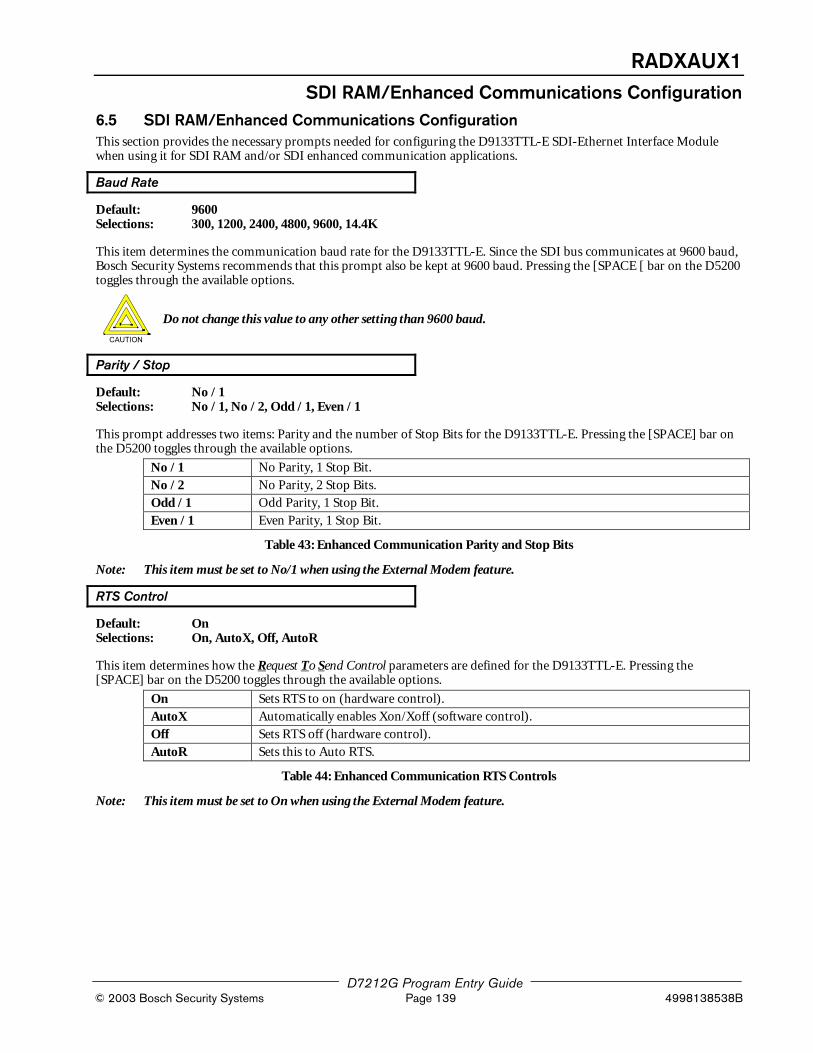
RADXAUX1SDI RAM/Enhanced Communications Configuration
D7212G Program Entry Guide © 2003 Bosch Security Systems Page 139 4998138538B
6.5 SDI RAM/Enhanced Communications ConfigurationThis section provides the necessary prompts needed for configuring the D9133TTL-E SDI-Ethernet Interface Modulewhen using it for SDI RAM and/or SDI enhanced communication applications.
Baud Rate
Default: 9600Selections: 300, 1200, 2400, 4800, 9600, 14.4K
This item determines the communication baud rate for the D9133TTL-E. Since the SDI bus communicates at 9600 baud,Bosch Security Systems recommends that this prompt also be kept at 9600 baud. Pressing the [SPACE [ bar on the D5200toggles through the available options.
Do not change this value to any other setting than 9600 baud.
Parity / Stop
Default: No / 1Selections: No / 1, No / 2, Odd / 1, Even / 1
This prompt addresses two items: Parity and the number of Stop Bits for the D9133TTL-E. Pressing the [SPACE] bar onthe D5200 toggles through the available options.
No / 1 No Parity, 1 Stop Bit.
No / 2 No Parity, 2 Stop Bits.
Odd / 1 Odd Parity, 1 Stop Bit.
Even / 1 Even Parity, 1 Stop Bit.
Table 43: Enhanced Communication Parity and Stop Bits
Note: This item must be set to No/1 when using the External Modem feature.
RTS Control
Default: OnSelections: On, AutoX, Off, AutoR
This item determines how the Request To Send Control parameters are defined for the D9133TTL-E. Pressing the[SPACE] bar on the D5200 toggles through the available options.
On Sets RTS to on (hardware control).
AutoX Automatically enables Xon/Xoff (software control).
Off Sets RTS off (hardware control).
AutoR Sets this to Auto RTS.
Table 44: Enhanced Communication RTS Controls
Note: This item must be set to On when using the External Modem feature.

RADXAUX1SDI RAM/Enhanced Communications Configuration
D7212G Program Entry Guide 4998138538B Page 140 © 2003 Bosch Security Systems
DTR Control
Default: OnSelections: On, AutoD, Off
This item determines how the Data Terminal Ready Control parameters are defined for the D9133TTL-E. Pressing the[SPACE] bar on the D5200 toggles through the available options.
On Sets DTR to on (hardware control).
AutoD Sets this to Auto DTR.
Off Sets DTR off (hardware control).
Table 45: Enhanced Communication DTR Controls
Note: This item must be set to On when using the External Modem feature.
D9133 Supervision
Default: NoSelections: Yes or No
This item determines whether the D9133TTL-E is supervised or not. If the D9133TTL-E is supervised, disconnecting itfrom the panel will create a TROUBLE SDI 88 event and the command center will annunciate a trouble tone and displaySERVC SDI 88.
Note: TROUBLE SDI 88 reports are always reported using Area 1’s Account number.
Yes Supervise the D9133TTL-E Network Interface Module.
No Do not supervise the D9133TTL-E Network Interface Module.
Base Port Number
Default: 7700Selections: 0 – 65535
The base port number is the port number of the cobox; e.g. 7700. This will be used in the future revision and is notneeded at this time.
6.5.1 Route Group AttemptsThis section determines how many times a Route Group will try the Primary destination before attempting the Backupdestination should the Primary destination fail. This entry applies to both Phone numbers and IP Addresses.
RG# 1 Attempt
Default: NoSelections: Yes or No
Note: This feature is not yet available with the D7212G.

RADXAUX1Miscellaneous
D7212G Program Entry Guide © 2003 Bosch Security Systems Page 141 4998138538B
6.6 Miscellaneous
Fire Supv Res Type
Default: 0Selections: 0, 1, 2
This item determines how the panels will transmit a Fire Supervision Restoral event.
0 The panel transmits a FIRE TROUBLE RESTORE when a Fire Supervision pointrestores to normal.
1 The panel transmits a FIRE ALARM RESTORE when a Fire Supervision point restores tonormal.
2 The panel transmits a FIRE SUPERVISION RESTORE when a Fire Supervision pointrestores to normal.
Table 46: Fire Supervision Restoral Events
Enable Protocol Type
Default: NoSelections: Yes, No
Not required at this time. Please leave at default value
Enable Anti Replay
Default: NoSelections: Yes, No
This feature is used primarily for two purposes:
Anti-Replay
Anti-replay is a strategy designed against replay attacks. This feature will prevent substitution of a panel/networkinterface module (NIM) solution for delivering events over a network.
A replay attack is when a “hacker” records a message that is sent over the network by Device A and replaces this messageat a later time while pretending to be Device A.
Application
Note
If this functionality is required, you must also enable the Anti-Replay functionality in the D6600 Receiver.Please refer to the D6600 Operation and Installation Guide (P/N: 39964) for further details.
Account Identification
The D6600 Receiver can identify the NetCom accounts by either the IP Address and/or the Account Number that isreceived in the message sent from the control/communicator. The Account Number that is transmitted in the messagewill always be Area 1's Account Number. Although up to ten (10) digits may be programmed for the Account number,only eight digits will be sent in the message to the D6600 receiver.
Fire Trouble Resound
Default: 0Selections: 0, 1, 2
This item determines if a fire trouble condition, although previously acknowledged and silenced at a command center,will automatically (locally) resound the fire trouble tone at 12:00pm, 12:00am, or not at all if the point is still in an off-normal state. Events are not generated at the time resound occurs.
0 Command centers will not re-sound the fire trouble tone.
1 Command centers will re-sound the fire trouble tone at 12:00 PM if any fire point that fallswithin the scope of a command center is in an off-normal condition.
2