4th wireless transport poc detailed report · sdn network architecture and configuration ... •...
TRANSCRIPT
4th Wireless Transport SDN Proof of Concept White Paper & Detailed Report V1 2017-06-29

Wireless Transport SDN PoC White Paper Version No.1
Page 2 of 32 © 2017 Open Networking Foundation
ONF Document Type: White Paper ONF Document Name: Wireless Transport SDN PoC White Paper Disclaimer
THIS SPECIFICATION IS PROVIDED “AS IS” WITH NO WARRANTIES WHATSOEVER, INCLUDING ANY WARRANTY OF MERCHANTABILITY, NONINFRINGEMENT, FITNESS FOR ANY PARTICULAR PURPOSE, OR ANY WARRANTY OTHERWISE ARISING OUT OF ANY PROPOSAL, SPECIFICATION OR SAMPLE.
Any marks and brands contained herein are the property of their respective owners. Open Networking Foundation 2275 E. Bayshore Road, Suite 103, Palo Alto, CA 94303 www.opennetworking.org
©2017 Open Networking Foundation. All rights reserved.
Open Networking Foundation, the ONF symbol, and OpenFlow are registered trademarks of the Open Networking Foundation, in the United States and/or in other countries. All other brands, products, or service names are or may be trademarks or service marks of, and are used to identify, products or services of their respective owners.
Wireless Transport SDN PoC White Paper Version No.1
Page 3 of 32 © 2017 Open Networking Foundation
1 Executive Summary ........................................................................................................................... 4
2 Introduction ......................................................................................................................................... 4 2.1 Mission of WTP and benefits of open SDN .................................................................................. 5 2.2 Overview of previous Proof of Concepts ...................................................................................... 6
2.2.1 First PoC ............................................................................................................................ 6 2.2.2 Second PoC ....................................................................................................................... 6 2.2.3 Third PoC ........................................................................................................................... 7
3 SDN Network Architecture and Configuration ................................................................................. 7 3.1 Overview ...................................................................................................................................... 7 3.2 PoC Test Network Setup .............................................................................................................. 9
4 Use Cases and Applications ........................................................................................................... 10 4.1 Applications based on MW information model ........................................................................... 11
4.1.1 Wireless power management .......................................................................................... 11 4.1.2 Performance monitoring management ............................................................................. 11 4.1.3 Network map visualization ............................................................................................... 12 4.1.4 Management of microwave devices ................................................................................. 12 4.1.5 Fault management ........................................................................................................... 12
4.2 Applications based on Synchronization model ........................................................................... 13 4.2.1 Management of PTP-capable devices ............................................................................. 14 4.2.2 Detection and visualization of synchronization path ........................................................ 14
4.3 Applications based on Ethernet model ....................................................................................... 15 4.3.1 Management of Ethernet-capable devices ...................................................................... 16 4.3.2 Path re-routing ................................................................................................................. 17
5 Test Results ...................................................................................................................................... 18
6 Conclusions ...................................................................................................................................... 18
7 Acknowledgments ............................................................................................................................ 19
8 Contributions .................................................................................................................................... 20 8.1 Applications based on MW Information model (TR-532) ........................................................... 20 8.2 Applications based on Synchronization model according to ITU-T G.8275.1 Telecom profile .. 23 8.3 Applications based on Ethernet model ....................................................................................... 24 8.4 Product simulator ....................................................................................................................... 25 8.5 Power Control application for Ethernet transport ....................................................................... 26 8.6 Mediator for microwave products ............................................................................................... 28
9 References ........................................................................................................................................ 30
10 Terminology .............................................................................................................................. 31
Wireless Transport SDN PoC White Paper Version No.1
Page 4 of 32 © 2017 Open Networking Foundation
1 Executive Summary This white paper provides an overview of the contents and results of the Proof of Concept (PoC) conducted from 26 to 29 June 2017 by the Wireless Transport Project (WTP) of the Open Networking Foundation (ONF) at Deutsche Telekom premises in Bonn (Germany).
This PoC was focused on demonstrating the capabilities and benefits of utilizing a common Information Model for multi-vendor control of wireless network elements through open management interfaces, as defined in the Wireless Transport Project of ONF Optical Transport Working Group (OTWG) and documented in the technical report TR-532 [TR532]. In addition some basic Ethernet capabilities were shown and the possibility to manage a synchronization network via SDN approach in order to distribute the frequency & phase/time information using PTP (IEEE 1588v2) [IEEE1588v2].
The PoC included wide participations from the wireless transport industry including operator representatives, microwave (MW) equipment vendors, integrators and applications providers. It followed the third PoC [WP_3PoC] organized in the last October 2016, where the Microwave Information Model was implemented and demonstrated by some vendors; moreover more use cases were shown.
Different uses cases were included in this PoC to demonstrate wireless transport SDN applications such as topology planning and discovery, with dynamic view in real time, configuration, discrepancy monitoring and detection, and event handling.
A standard OpenDaylight (ODL) version was used as the SDN controller. Mediators were used for translating the information model to vendor specific configurations.
All vendors implemented the model and completed all the test cases successfully demonstrating the viability of the concept for using a common information model for configuring and management of wireless network elements using open management interfaces.
2 Introduction The 4th Wireless Transport Proof of Concept (PoC) took place from 26 to 29 June at Deutsche Telekom premises in Bonn, Germany.
This 4th PoC had 3 main objectives:
1. Continue to expand on the ONF Microwave Information Model standard (TR532) [TR532]
2. Show applications based on the Synchronization model per ITU-T G.8275.1 Telecom profile
3. Show applications based on an ONF derived Ethernet model
These objectives / use cases are explained in Section 4 and results are explained in Section 5.
All the codes (applications) developed during the 4th PoC are stored and publically available as open source at CENTENNIAL GitHUB [CENTEN].
The PoC was supported by representatives from the wireless transport eco system including operators, equipment vendors, integrators and application providers – in total 19 participating companies.
The following equipment vendors participated in the PoC with their equipment:
• Ceragon
• Ericsson
• Fujitsu
• Huawei
• NEC
• Nokia
Wireless Transport SDN PoC White Paper Version No.1
Page 5 of 32 © 2017 Open Networking Foundation
• SIAE
• ZTE
• ADVA Optical Networking
• DragonWave
• Aviat
• ELVA-1
• Intracom Telecom
The following integrators and application providers provided buildings block and applications:
• Frinx
• Highstreet Technologies
Content and organizational support for the PoC was provided by the following operators:
• Deutsche Telekom
• AT&T
• Telefónica
The measurement equipment (traffic generator and analyser) was provided by:
• Spirent
2.1 Mission of WTP and benefits of open SDN
The mission and long-term targets of ONF Wireless Transport Project are as follows:
• Adoption of SDN architecture and principles for wireless transport networks. Identification of and addressing of different use cases.
• Definition and standardization of open interfaces and open source information models – integration of information models into the open source ecosystem. Open standardized interfaces allow connecting of multi-vendor devices to an open source SDN Controller and development of independent third-party applications (“network programming” – Network Function Virtualization (NFV)). The operators/service providers will not differentiate by the functionality, which is provided by the controller itself, but by the applications.
The benefits of an SDN-based open standardized system are as follows:
• Vendor-specific element management systems can be substituted by a single generic element management system that leverages from open standardized Southbound interfaces. The myriad of tools for network planning and operations could be converged on a single platform (e.g. OpenDaylight) on which seamlessly integrated network applications would provide that functionality. This would greatly reduce the complexity of the overall network management solution and thus save time and money.
Wireless Transport SDN PoC White Paper Version No.1
Page 6 of 32 © 2017 Open Networking Foundation
• Decoupling the functions from the device to centralized controller will reduce the duration and costs of homologation and integration processes - a new function is configured and tested just once.
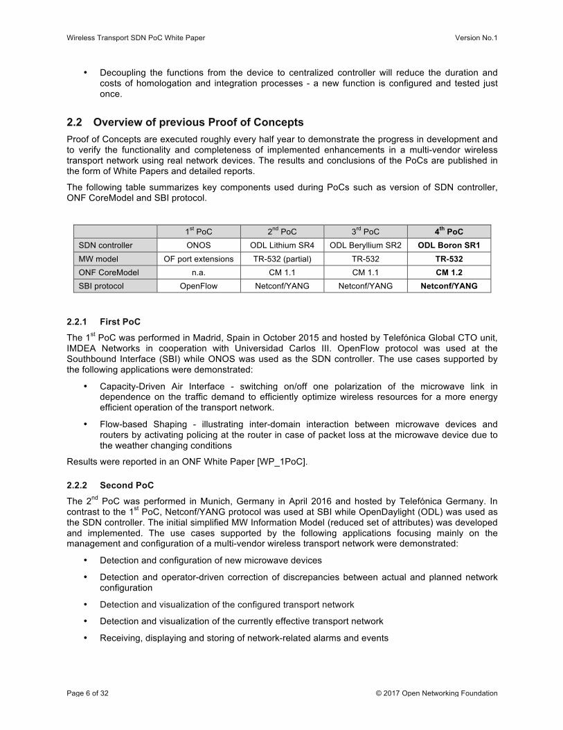
2.2 Overview of previous Proof of Concepts Proof of Concepts are executed roughly every half year to demonstrate the progress in development and to verify the functionality and completeness of implemented enhancements in a multi-vendor wireless transport network using real network devices. The results and conclusions of the PoCs are published in the form of White Papers and detailed reports.
The following table summarizes key components used during PoCs such as version of SDN controller, ONF CoreModel and SBI protocol.
1st PoC 2nd PoC 3rd PoC 4th PoC SDN controller ONOS ODL Lithium SR4 ODL Beryllium SR2 ODL Boron SR1 MW model OF port extensions TR-532 (partial) TR-532 TR-532 ONF CoreModel n.a. CM 1.1 CM 1.1 CM 1.2 SBI protocol OpenFlow Netconf/YANG Netconf/YANG Netconf/YANG
2.2.1 First PoC
The 1st PoC was performed in Madrid, Spain in October 2015 and hosted by Telefónica Global CTO unit, IMDEA Networks in cooperation with Universidad Carlos III. OpenFlow protocol was used at the Southbound Interface (SBI) while ONOS was used as the SDN controller. The use cases supported by the following applications were demonstrated:
• Capacity-Driven Air Interface - switching on/off one polarization of the microwave link in dependence on the traffic demand to efficiently optimize wireless resources for a more energy efficient operation of the transport network.
• Flow-based Shaping - illustrating inter-domain interaction between microwave devices and routers by activating policing at the router in case of packet loss at the microwave device due to the weather changing conditions
Results were reported in an ONF White Paper [WP_1PoC].
2.2.2 Second PoC
The 2nd PoC was performed in Munich, Germany in April 2016 and hosted by Telefónica Germany. In contrast to the 1st PoC, Netconf/YANG protocol was used at SBI while OpenDaylight (ODL) was used as the SDN controller. The initial simplified MW Information Model (reduced set of attributes) was developed and implemented. The use cases supported by the following applications focusing mainly on the management and configuration of a multi-vendor wireless transport network were demonstrated:
• Detection and configuration of new microwave devices
• Detection and operator-driven correction of discrepancies between actual and planned network configuration
• Detection and visualization of the configured transport network
• Detection and visualization of the currently effective transport network
• Receiving, displaying and storing of network-related alarms and events
Wireless Transport SDN PoC White Paper Version No.1
Page 7 of 32 © 2017 Open Networking Foundation
Results and conclusions were reported in an ONF White paper [WP_2PoC], and the MW Information Model is described in TR-532 [TR532].
2.2.3 Third PoC
The 3rd PoC was performed in New Jersey, USA in October 2016 and hosted by AT&T in cooperation with WINLAB (Wireless Information Network Laboratory) research centre at Rutgers University. The complete MW Information Model (including all the attributes) was developed and implemented. The use cases supported by the following applications were demonstrated:
• The above mentioned applications from the 2nd PoC
• Spectrum management – comparison of configured and planned frequencies and reallocation in case of mismatch
• Closed-loop automation (“zero-touch deployment and maintenance”) – a basic response to external/internal/time triggers
Results and conclusions were reported in an ONF White paper [WP_3PoC], and the MW Information Model is described in TR-532 [TR532].
3 SDN Network Architecture and Configuration
3.1 Overview The overall SDN architecture and configuration of the test setup in the 4th ONF WTP PoC is illustrated in Figure 1 below:
Wireless Transport SDN PoC White Paper Version No.1
Page 8 of 32 © 2017 Open Networking Foundation
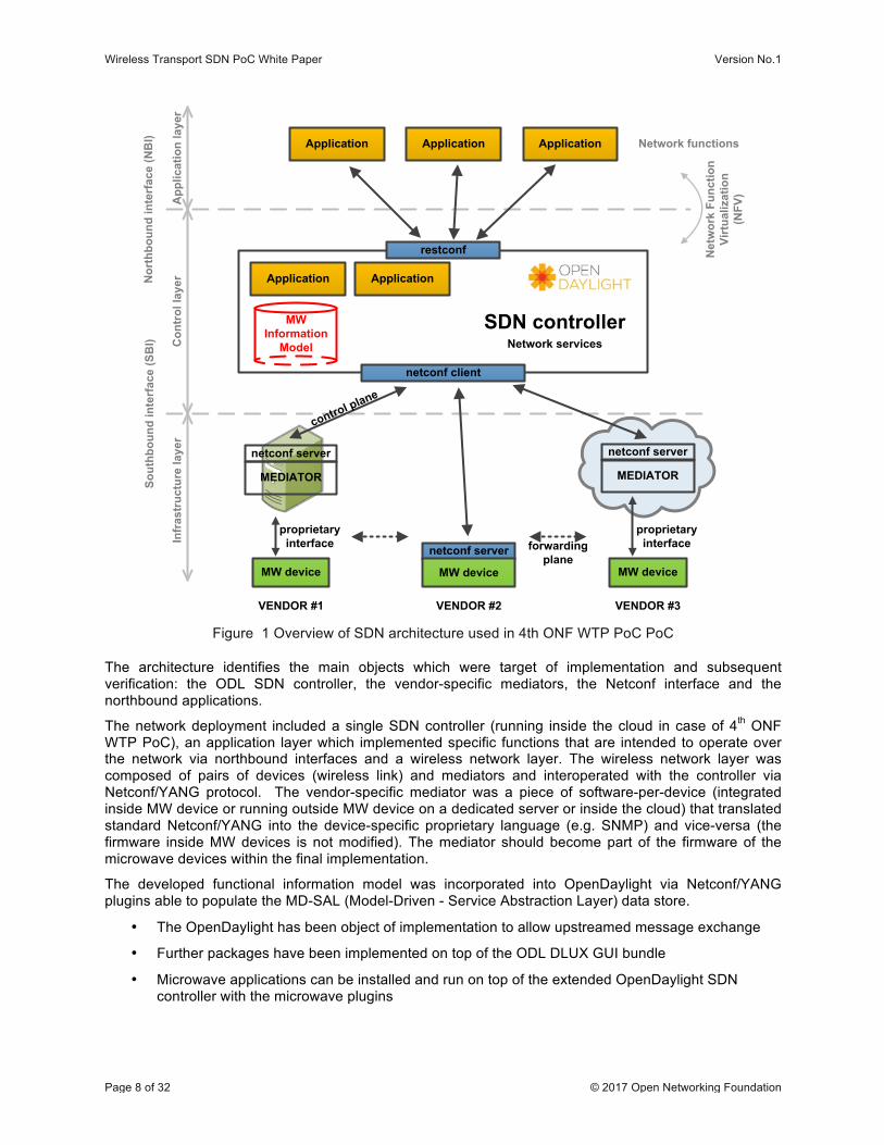
Figure 1 Overview of SDN architecture used in 4th ONF WTP PoC PoC
The architecture identifies the main objects which were target of implementation and subsequent verification: the ODL SDN controller, the vendor-specific mediators, the Netconf interface and the northbound applications.
The network deployment included a single SDN controller (running inside the cloud in case of 4th ONF WTP PoC), an application layer which implemented specific functions that are intended to operate over the network via northbound interfaces and a wireless network layer. The wireless network layer was composed of pairs of devices (wireless link) and mediators and interoperated with the controller via Netconf/YANG protocol. The vendor-specific mediator was a piece of software-per-device (integrated inside MW device or running outside MW device on a dedicated server or inside the cloud) that translated standard Netconf/YANG into the device-specific proprietary language (e.g. SNMP) and vice-versa (the firmware inside MW devices is not modified). The mediator should become part of the firmware of the microwave devices within the final implementation.
The developed functional information model was incorporated into OpenDaylight via Netconf/YANG plugins able to populate the MD-SAL (Model-Driven - Service Abstraction Layer) data store.
• The OpenDaylight has been object of implementation to allow upstreamed message exchange
• Further packages have been implemented on top of the ODL DLUX GUI bundle
• Microwave applications can be installed and run on top of the extended OpenDaylight SDN controller with the microwave plugins
Application Application
Application ApplicationApplication
MW Information
Model
netconf client
netconf server
MEDIATOR
MW device
VENDOR #1
restconf
SDN controllerNetwork services
proprietary interfaceIn
fras
truc
ture
laye
rC
ontr
ol la
yer
App
licat
ion
laye
r
Sout
hbou
nd in
terf
ace
(SB
I)N
orth
boun
d in
terf
ace
(NB
I)
forwarding plane
control plane
Network functions
Net
wor
k Fu
nctio
n Vi
rtua
lizat
ion
(NFV
)
netconf server
MW device
VENDOR #2
netconf server
MEDIATOR
MW device
VENDOR #3
proprietary interface
Wireless Transport SDN PoC White Paper Version No.1
Page 9 of 32 © 2017 Open Networking Foundation
Netconf has been chosen over OpenFlow as a protocol for configuration and management of the microwave devices for several reasons. It is by design a general-purpose management protocol, while OpenFlow is primarily intended for operating the traffic forwarding plane of the device (e.g. traffic flows). Also, YANG can be used to describe the data model for Netconf, coming to a representation of a clearer and more readable information model. Instead of implementing Netconf protocol handlers in the devices, some external mediators (adapters) were used for translating the Netconf/YANG Microwave Information Model to/from the existing proprietary management protocols of each vendor’s devices. This approach allowed:
• being more flexible
• saving time in the development and the debugging phase
• sharing code between PoC participants
In addition to the mediators required to connect the physical network elements (NEs), an NE simulator (“Default Values Mediator”) has been developed. It behaves like a generic NE, which allows re-demonstrating the use cases and applications from the PoC without the actual need and installation of physical microwave equipment. This supports ONF WTP plans on maintaining a server running a demonstration and testing environment for future application developments.
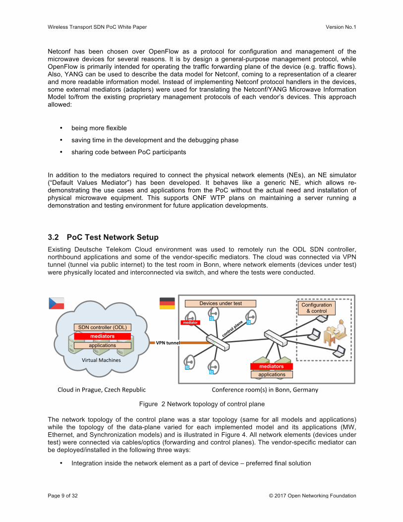
3.2 PoC Test Network Setup Existing Deutsche Telekom Cloud environment was used to remotely run the ODL SDN controller, northbound applications and some of the vendor-specific mediators. The cloud was connected via VPN tunnel (tunnel via public internet) to the test room in Bonn, where network elements (devices under test) were physically located and interconnected via switch, and where the tests were conducted.
Figure 2 Network topology of control plane
The network topology of the control plane was a star topology (same for all models and applications) while the topology of the data-plane varied for each implemented model and its applications (MW, Ethernet, and Synchronization models) and is illustrated in Figure 4. All network elements (devices under test) were connected via cables/optics (forwarding and control planes). The vendor-specific mediator can be deployed/installed in the following three ways:
• Integration inside the network element as a part of device – preferred final solution
VPN tunnel
Conference room(s) in Bonn, GermanyCloud in Prague, Czech Republic
SDN controller (ODL)
mediators
applications
mediators
control p
lane
applications
Devices under test
mediator
Virtual Machines
Configuration & control
Wireless Transport SDN PoC White Paper Version No.1
Page 10 of 32 © 2017 Open Networking Foundation
• Installation inside the cloud running on dedicated Virtual Machine – temporary solution • Installation on the local server/computer – temporary solution
All three deployment options were successfully demonstrated during the 4th ONF WTP PoC.
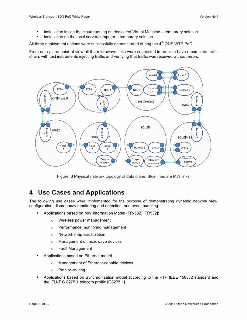
From data-plane point of view all the microwave links were connected in order to have a complete traffic chain, with test instruments injecting traffic and verifying that traffic was received without errors:
south-‐west
south
north-‐east
NEC-‐Z
north-‐west north
east
south-‐east
west
Nokia-‐Z
Nokia-‐A
Ceragon-‐Z
Ceragon-‐A
Fujitsu-‐Z#
Fujitsu-‐A
Huawei-‐ZHuawei-‐A
NEC-‐AZTE-‐ZZTE-‐A
SIAE-‐ZSIAE-‐A
Ericsson-‐ZEricsson-‐A
Dragon Wave-‐Z
Dragon Wave-‐A
ELVA-‐1-‐ZELVA-‐1-‐
A
IntracomTelecom
Z
IntracomTelecomA
Aviat-‐ZAviat-‐A
Figure 3 Physical network topology of data plane. Blue lines are MW links.
4 Use Cases and Applications The following use cases were implemented for the purpose of demonstrating dynamic network view, configuration, discrepancy monitoring and detection, and event handling:
• Applications based on MW Information Model (TR-532) [TR532]:
o Wireless power management
o Performance monitoring management
o Network map visualization
o Management of microwave devices
o Fault Management
• Applications based on Ethernet model
o Management of Ethernet-capable devices
o Path re-routing
• Applications based on Synchronization model according to the PTP IEEE 1588v2 standard and the ITU-T G.8275.1 telecom profile [G8275.1]
Wireless Transport SDN PoC White Paper Version No.1
Page 11 of 32 © 2017 Open Networking Foundation
o Management of PTP-capable devices
o Detection and visualization of synchronization path
Brief description of each application is provided in the subsections below.
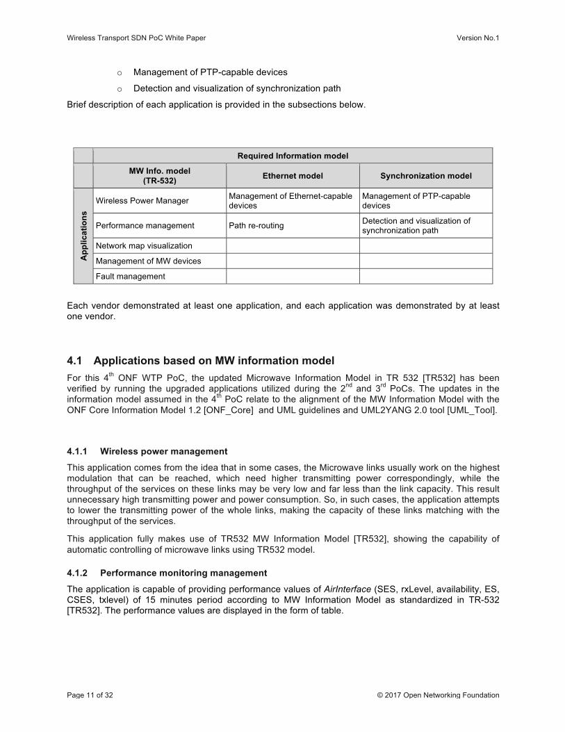
Required Information model
MW Info. model (TR-532) Ethernet model Synchronization model
App
licat
ions
Wireless Power Manager Management of Ethernet-capable devices
Management of PTP-capable devices
Performance management Path re-routing Detection and visualization of synchronization path
Network map visualization
Management of MW devices
Fault management
Each vendor demonstrated at least one application, and each application was demonstrated by at least one vendor.
4.1 Applications based on MW information model For this 4th ONF WTP PoC, the updated Microwave Information Model in TR 532 [TR532] has been verified by running the upgraded applications utilized during the 2nd and 3rd PoCs. The updates in the information model assumed in the 4th PoC relate to the alignment of the MW Information Model with the ONF Core Information Model 1.2 [ONF_Core] and UML guidelines and UML2YANG 2.0 tool [UML_Tool].
4.1.1 Wireless power management
This application comes from the idea that in some cases, the Microwave links usually work on the highest modulation that can be reached, which need higher transmitting power correspondingly, while the throughput of the services on these links may be very low and far less than the link capacity. This result unnecessary high transmitting power and power consumption. So, in such cases, the application attempts to lower the transmitting power of the whole links, making the capacity of these links matching with the throughput of the services.
This application fully makes use of TR532 MW Information Model [TR532], showing the capability of automatic controlling of microwave links using TR532 model.
4.1.2 Performance monitoring management
The application is capable of providing performance values of AirInterface (SES, rxLevel, availability, ES, CSES, txlevel) of 15 minutes period according to MW Information Model as standardized in TR-532 [TR532]. The performance values are displayed in the form of table.
Wireless Transport SDN PoC White Paper Version No.1
Page 12 of 32 © 2017 Open Networking Foundation
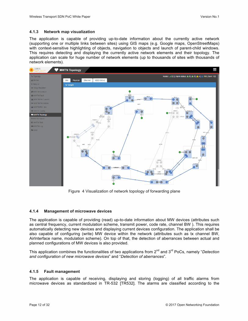
4.1.3 Network map visualization
The application is capable of providing up-to-date information about the currently active network (supporting one or multiple links between sites) using GIS maps (e.g. Google maps, OpenStreetMaps) with context-sensitive highlighting of objects, navigation to objects and launch of parent-child windows. This requires detecting and displaying the currently active network elements and their topology. The application can scale for huge number of network elements (up to thousands of sites with thousands of network elements).
Figure 4 Visualization of network topology of forwarding plane
4.1.4 Management of microwave devices
The application is capable of providing (read) up-to-date information about MW devices (attributes such as central frequency, current modulation scheme, transmit power, code rate, channel BW ). This requires automatically detecting new devices and displaying current devices configuration. The application shall be also capable of configuring (write) MW device within the network (attributes such as tx channel BW, AirInterface name, modulation scheme). On top of that, the detection of aberrances between actual and planned configurations of MW devices is also provided.
This application combines the functionalities of two applications from 2nd and 3rd PoCs, namely “Detection and configuration of new microwave devices” and “Detection of aberrances”.
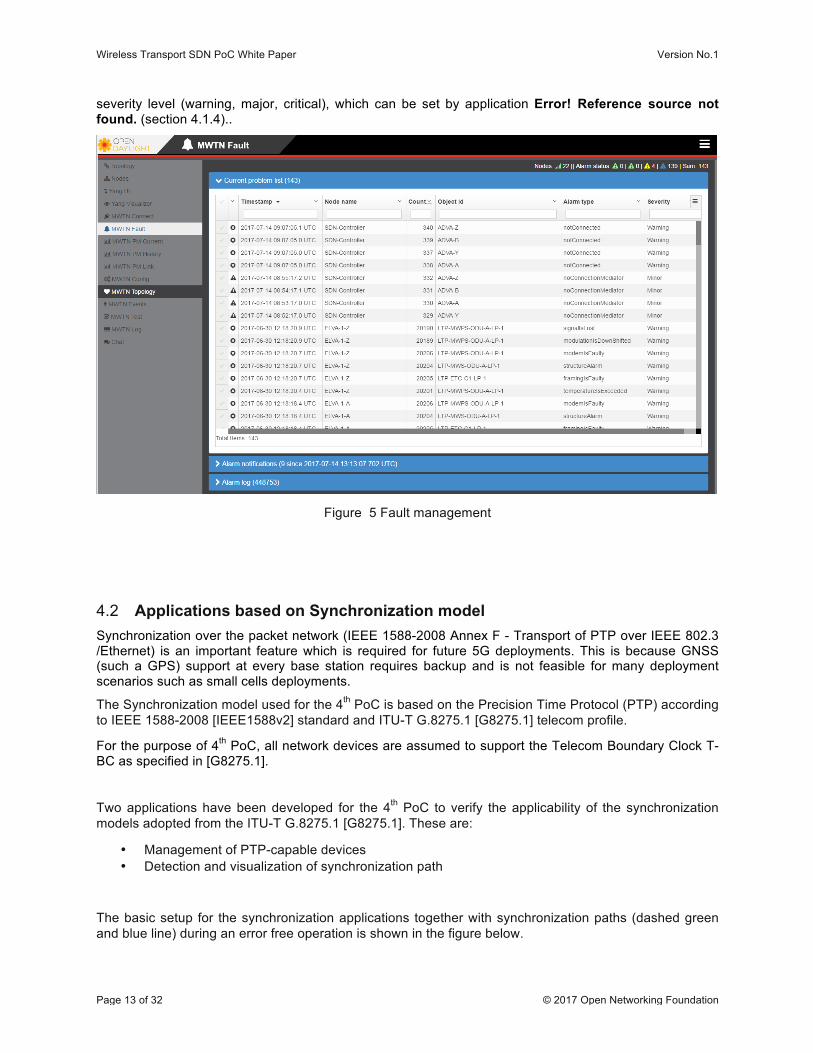
4.1.5 Fault management
The application is capable of receiving, displaying and storing (logging) of all traffic alarms from microwave devices as standardized in TR-532 [TR532]. The alarms are classified according to the
Wireless Transport SDN PoC White Paper Version No.1
Page 13 of 32 © 2017 Open Networking Foundation
severity level (warning, major, critical), which can be set by application Error! Reference source not found. (section 4.1.4)..
Figure 5 Fault management
4.2 Applications based on Synchronization model Synchronization over the packet network (IEEE 1588-2008 Annex F - Transport of PTP over IEEE 802.3 /Ethernet) is an important feature which is required for future 5G deployments. This is because GNSS (such a GPS) support at every base station requires backup and is not feasible for many deployment scenarios such as small cells deployments.
The Synchronization model used for the 4th PoC is based on the Precision Time Protocol (PTP) according to IEEE 1588-2008 [IEEE1588v2] standard and ITU-T G.8275.1 [G8275.1] telecom profile.
For the purpose of 4th PoC, all network devices are assumed to support the Telecom Boundary Clock T-BC as specified in [G8275.1].
Two applications have been developed for the 4th PoC to verify the applicability of the synchronization models adopted from the ITU-T G.8275.1 [G8275.1]. These are:
• Management of PTP-capable devices • Detection and visualization of synchronization path
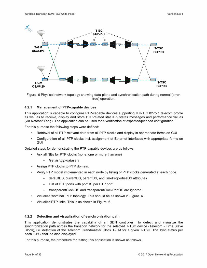
The basic setup for the synchronization applications together with synchronization paths (dashed green and blue line) during an error free operation is shown in the figure below.
Wireless Transport SDN PoC White Paper Version No.1
Page 14 of 32 © 2017 Open Networking Foundation
Figure 6 Physical network topology showing data-plane and synchronisation path during normal (error-free) operation.
4.2.1 Management of PTP-capable devices
This application is capable to configure PTP-capable devices supporting ITU-T G.8275.1 telecom profile as well as to receive, display and store PTP-related status & states messages and performance values (via Netconf/Yang). The application can be used for a verification of expected/planned configuration.
For this purpose the following steps were defined:
• Retrieval of all PTP-relevant data from all PTP clocks and display in appropriate forms on GUI
• Configuration of all PTP clocks incl. assignment of Ethernet interfaces with appropriate forms on GUI
Detailed steps for demonstrating the PTP-capable devices are as follows:
• Ask all NEs for PTP clocks (none, one or more than one)
– Get list ptp-datasets
• Assign PTP clocks to PTP domain.
• Verify PTP model implemented in each node by listing of PTP clocks generated at each node.
– defaultDS, currentDS, parentDS, and timePropertiesDS attributes
– List of PTP ports with portDS per PTP port
– transparentClockDS and transparentClockPortDS are ignored.
• Visualize ‘nominal’ PTP topology. This should be as shown in Figure 6.
• Visualize PTP links. This is as shown in Figure 6.
4.2.2 Detection and visualization of synchronization path
This application demonstrates the capability of an SDN controller to detect and visualize the synchronization path across the transport network for the selected T-TSC device (Telecom - Time Slave Clock), i.e. detection of the Telecom Grandmaster Clock T-GM for a given T-TSC. The sync status per each T-BC shall be also displayed.
For this purpose, the procedure for testing this application is shown as follows.
Wireless Transport SDN PoC White Paper Version No.1
Page 15 of 32 © 2017 Open Networking Foundation
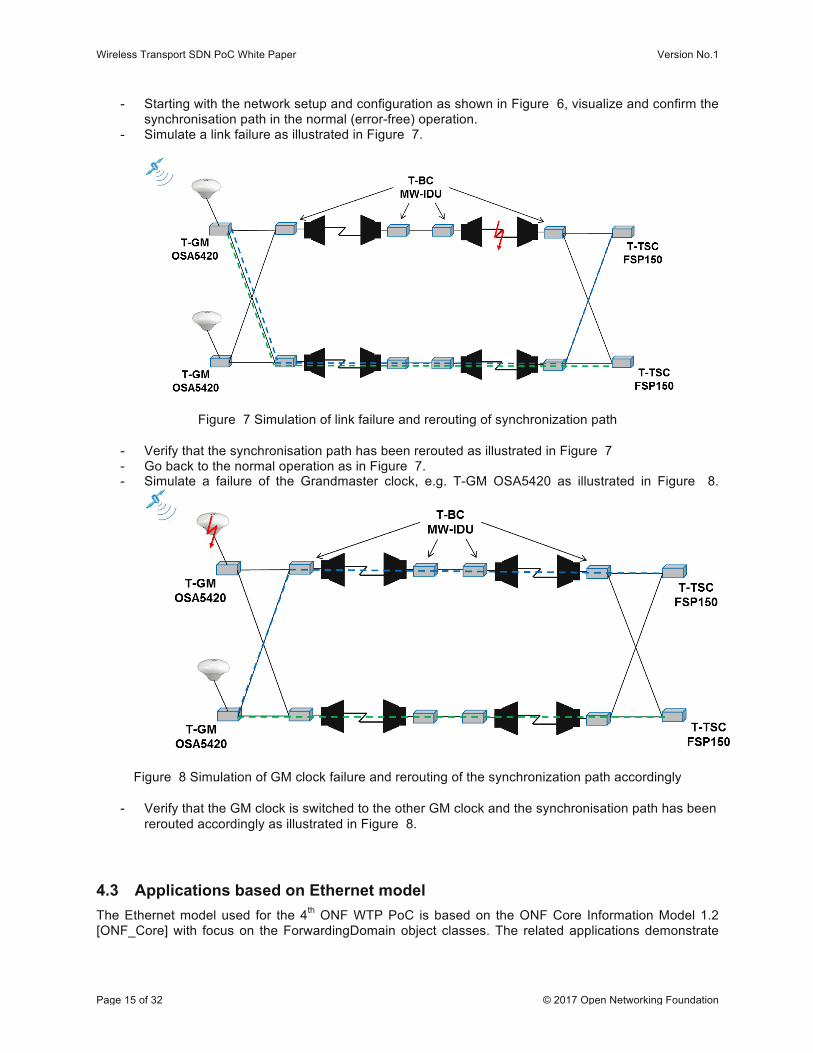
- Starting with the network setup and configuration as shown in Figure 6, visualize and confirm the synchronisation path in the normal (error-free) operation.
- Simulate a link failure as illustrated in Figure 7.
Figure 7 Simulation of link failure and rerouting of synchronization path
- Verify that the synchronisation path has been rerouted as illustrated in Figure 7 - Go back to the normal operation as in Figure 7. - Simulate a failure of the Grandmaster clock, e.g. T-GM OSA5420 as illustrated in Figure 8.
Figure 8 Simulation of GM clock failure and rerouting of the synchronization path accordingly
- Verify that the GM clock is switched to the other GM clock and the synchronisation path has been rerouted accordingly as illustrated in Figure 8.
4.3 Applications based on Ethernet model The Ethernet model used for the 4th ONF WTP PoC is based on the ONF Core Information Model 1.2 [ONF_Core] with focus on the ForwardingDomain object classes. The related applications demonstrate
Wireless Transport SDN PoC White Paper Version No.1
Page 16 of 32 © 2017 Open Networking Foundation
configuration of the Ethernet capable devices such as creation, modification and deletion and detection and rerouting of Ethernet flows when a problem with a link along a path is detected.
Two applications are defined and demonstrated for that purpose:
- Management of Ethernet capable devices. - Path rerouting
south-‐westsouth
north-‐eastNEC-‐Z
Spirent Traffic Analyzer
north-‐westnorth
east
south-‐eastwest
Nokia-‐Z#6
Nokia-‐A#6 91
Ceragon-‐Z#6
Ceragon-‐A#6
32
Fujitsu-‐Z#6
Fujitsu-‐A#6
61
Huawei-‐Z#6
Huawei-‐A#6 71
#6
NEC-‐A#6 81
ZTE-‐Z#6
ZTE-‐A#6 111
SIAE-‐Z#6
SIAE-‐A#6 101
Ericsson-‐Z#6
Ericsson-‐A#6 31
ADVA-‐ZT-‐TSC
#3
ADVA-‐YT-‐TSC
#1
#2
#1
#2
#3
#4
#4
#5
#5
#5
#5
#3
#5#5#5#5
#5#5
#5
#4
#4
#4
#4
#3
#3
#4
#1
#2
#2
#4
#4
Dragon Wave-‐Z#6
Dragon Wave-‐A #6 41#2
#6
ELVA-‐1-‐Z#6
ELVA-‐1-‐A#6
121
#7
#2
#2
#8
Intracom-‐Z#6Intracom-‐A #6 131#2#2
Aviat-‐Z#6
Aviat-‐A#6 21
#5#5
#5
#5
#5 #5
#5
#6 LTP ETC
LTP ETY
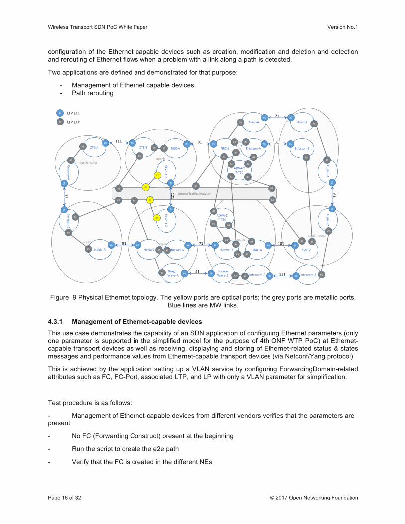
Figure 9 Physical Ethernet topology. The yellow ports are optical ports; the grey ports are metallic ports. Blue lines are MW links.
4.3.1 Management of Ethernet-capable devices
This use case demonstrates the capability of an SDN application of configuring Ethernet parameters (only one parameter is supported in the simplified model for the purpose of 4th ONF WTP PoC) at Ethernet-capable transport devices as well as receiving, displaying and storing of Ethernet-related status & states messages and performance values from Ethernet-capable transport devices (via Netconf/Yang protocol).
This is achieved by the application setting up a VLAN service by configuring ForwardingDomain-related attributes such as FC, FC-Port, associated LTP, and LP with only a VLAN parameter for simplification.
Test procedure is as follows:
- Management of Ethernet-capable devices from different vendors verifies that the parameters are present
- No FC (Forwarding Construct) present at the beginning
- Run the script to create the e2e path
- Verify that the FC is created in the different NEs
Wireless Transport SDN PoC White Paper Version No.1
Page 17 of 32 © 2017 Open Networking Foundation
- Start with traffic running over the main path
- Verify counters on instrument
4.3.2 Path re-routing
The purpose of this application is to show interaction between the physical layer of the microwave transport and the Ethernet protocol layer. In particular, bandwidth variation caused by Adaptive Modulation shall influence service routing. Within the application, the services shall be distinguished by following criterion:
• Guaranteed Bit Rate to be Assured (GBA)
Routing of the service shall be successful, if the GBA of the allocated service is lower than the capacity (calculated from configuration and status information of the physical layer) of all links within the path of the service
Routing shall be calculated according to the following algorithm:
• For all links along this path, the capacity should be checked. If capacity of any link along the path is lower than GBA of the routed service, then another path fulfilling the GBA criterion will be selected.
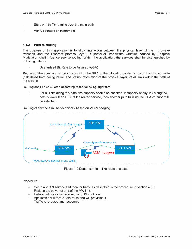
Routing of service shall be technically based on VLAN bridging.
Figure 10 Demonstration of re-route use case
Procedure:
- Setup a VLAN service and monitor traffic as described in the procedure in section 4.3.1 - Reduce the power of one of the MW links - Failure notification is received by SDN controller - Application will recalculate route and will provision it - Traffic is rerouted and recovered
Wireless Transport SDN PoC White Paper Version No.1
Page 18 of 32 © 2017 Open Networking Foundation
5 Test Results
The wireless transport equipment vendors and application providers listed in section 2 participated successfully in the tests. The tests were performed with an OpenDaylight (version Boron SR1) SDN controller. Additional functions required for the PoC use cases were provided by various SDN applications which had been implemented for the purpose of PoC and integrated into the SDN controller (see section 4).
The same south bound interface (using NETCONF protocol and YANG data models) was used between the SDN controller and the mediators of all vendors. The interfaces between mediators and network elements were proprietary interfaces which were not subject of the tests in this PoC.
The first series of tests demonstrated the application of the final version of the Microwave Information Model (as documented in the technical report TR-532 [TR532]) for managing a network of microwave equipment. All network elements were visible in a graphical representation of the PoC network in the related northbound application. Microwave specific data for each network element could be explored in the application. The configuration of the network was then modified in two ways: by switching off the transmitter of one link through the GUI respectively by increasing the attenuation of one link. As a consequence, the affected links provided less or no capacity and the overall capacity of the network was reduced. This effect could be seen both at the application and at the GUI of the traffic analyzer. The original capacity was restored as soon as the respective configuration was reverted to the initial values. The changes of configuration also triggered the network elements to report alarms which were forwarded as NETCONF notifications to the controller and displayed at the northbound application.
The second series of tests demonstrated the management of the Precision Timing Protocol (PTP) described in IEEE 1588 v2 [IEEE1588v2]. The application showed a graphical representation of the synchronization paths based on the data retrieved from the network elements. The PTP specific data for each network element could be explored at the application. The configuration of the network was then modified by switching off the link to one of the two Grandmaster clocks. As a consequence, the whole network synchronized on the second Grandmaster clock. The updated parent and Grandmaster clock identities could be seen at the application.
The third series of tests demonstrated the rerouting of Ethernet traffic transported over the microwave links. The rerouting application, first, established a path for Ethernet traffic by configuring a Layer 2 connection (VLAN) in each of the network elements along the path. Then a path degradation was simulated by manually reducing the modulation of one MW link. The resulting reduced capacity was detected by the application which then deleted the VLANs in the existing path and created new VLANs in the network elements along the new path. The traffic analyzer GUI showed that the traffic was restored.
6 Conclusions
The 4th Wireless Transport SDN PoC has reaffirmed the importance of the Wireless Transport Model (as documented in TR-532), for the adoption of SDN in the Wireless Transport Domain. In this PoC applications from the previous PoCs as well as new applications have been successfully tested and demonstrated by a larger group of vendors (in total 13 vendors). This shows that the model effectively covers the different aspects of operating and controlling Wireless Transport network elements in a SDN network.
After ONF Microwave Information Model (TR-532) has been released at the end of 2016, it has been widely adopted by the microwave vendors. In total 12 microwave/millimeter wave equipment vendors have implemented it, and demonstrated it during the PoC. As a matter of fact, all the significant providers of microwave equipment were attending the PoC, some of them for the first time. This proves the maturity of the model and the commitment of all the significant equipment vendors to provide a standard interface
Wireless Transport SDN PoC White Paper Version No.1
Page 19 of 32 © 2017 Open Networking Foundation
that will facilitate the operator ability to install them as part of multi-vendor SDN Wireless Transport network.
The PoC has proved to be a significant step toward common way of controlling and managing Wireless Transport Networks including Microwave, Ethernet connectivity and Network synchronization allowing non-proprietary open source SDN controller (e.g. OpenDaylight) to manage multi-vendor wireless transport networks. This will enable the operators to control all aspects of the network elements. It will facilitate the ability to have multi-vendor, multi-technology, multi-layer control, and advance innovative applications that control and optimize the different aspects of a network and not only microwave specific aspects.
All the developed applications have been successfully executed on top of the SDN controller toward different network elements implementing the same information model. This has been possible thanks to the fact that the same southbound interface was implemented by all vendors, and it adds another reason to implement the same model.
This PoC does not conclude the activities of ONF WTP, that need to work to extend the standard models for Ethernet ports control, Ethernet connectivity, Quality of Service model and others. This can be done by taking advantage of models developed by other standardization teams and adapting them to the ONF architecture. For this purpose, the PoC demonstrated that the Microwave Transport SDN Network architecture can smoothly integrate models defined by different standardization bodies (e.g. IETF model for IEEE1588 PTP).
Next target for WT activities will also include coordination with other domains and layers of the network (e.g. RAN, Core, OTN) to achieve a multi-layer and multi-domain hierarchical SDN solely based on open source models and open interfaces
7 Acknowledgments Thank you to Deutsche Telekom for hosting this event and for the perfect organization in terms of logistic and resources, in particular to Petr Jurcik, Thomas Kessler and Dimitris Siomos for the effort spent and the personal commitment for the success of the event. Thank you to all the team participating to the event (AT&T, Telefonica, Deutsche Telekom, ADVA, Aviat, Ceragon, DragonWave, ELVA-1, Ericsson, Fujitsu, Huawei, Intracom Telecom, NEC, Nokia, SIAE, ZTE, Highstreet Technologies, FRINX, Spirent).
Finally, thank you to the contributors and reviewers to the various sections of this White Paper, namely:
- Alexandru Stancu – Ceragon
- James Ries – Nokia
- Michael Binder – Ericsson
- Yossi Victor – Ceragon
- Alfons Mittermaier– Highstreet Technology
- Martin Skorupski – Highstreet Technology
- Nader Zein – NEC
- Lukáš Beleš - FRINX
- Giorgio Cazzaniga – SM Optics (SIAE Microelettronica group)
- Petr Jurcik - DT
- Thomas Kessler - DT
- Yang Yongang - ZTE
Wireless Transport SDN PoC White Paper Version No.1
Page 20 of 32 © 2017 Open Networking Foundation
8 Contributions
8.1 Applications based on MW Information model (TR-532) Context
The basic building blocks (GET requests, SET requests, notifications) of a south bound interface from SDN controller to a NetConf server were already shown in previous proof-of-concepts. Due to the introduction of yang naming conventions, it was necessary to refactor and update existing applications. New applications were created to automate the communication.
MWTN Connect had the same functionality as in previous PoC, but can now fetch data directly from the devices in 3rd and 4th PoC format to store them in a database as 4th PoC format.
MWTN Config was updated to display data according to the 3rd PoC and 4th PoC format and to configure ONF-TR-532 (4th PoC format) attributes. In addition the configuration for Ethernet and PTP was added – please see next chapters.
MWTN Fault collects all ONF-TR-532 ProblemNotifications and stores them in a database. A network wide current alarms list is derived from the received raised and cleared alarms together with the current problem list of the NetConf servers (Mediators, devices).
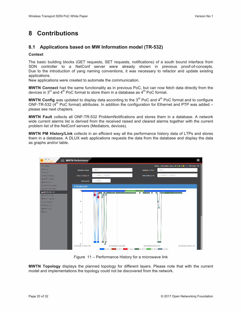
MWTN PM History/Link collects in an efficient way all the performance history data of LTPs and stores them in a database. A DLUX web applications requests the data from the database and display the data as graphs and/or table.
Figure 11 – Performance History for a microwave link
MWTN Topology displays the planned topology for different layers. Please note that with the current model and implementations the topology could not be discovered from the network.
Wireless Transport SDN PoC White Paper Version No.1
Page 21 of 32 © 2017 Open Networking Foundation
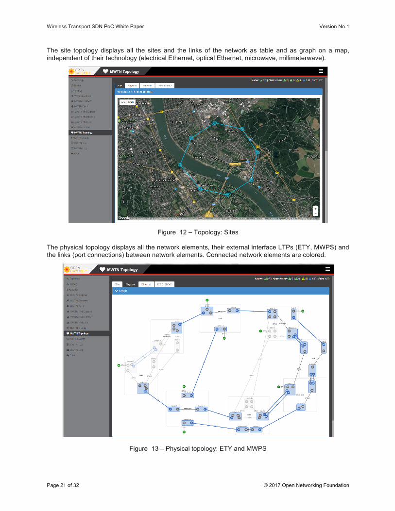
The site topology displays all the sites and the links of the network as table and as graph on a map, independent of their technology (electrical Ethernet, optical Ethernet, microwave, millimeterwave).
Figure 12 – Topology: Sites
The physical topology displays all the network elements, their external interface LTPs (ETY, MWPS) and the links (port connections) between network elements. Connected network elements are colored.
Figure 13 – Physical topology: ETY and MWPS
Wireless Transport SDN PoC White Paper Version No.1
Page 22 of 32 © 2017 Open Networking Foundation
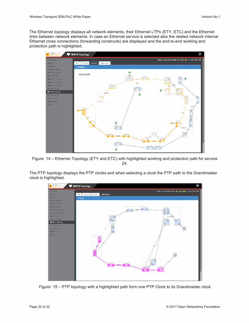
The Ethernet topology displays all network elements, their Ethernet LTPs (ETY, ETC) and the Ethernet links between network elements. In case an Ethernet service is selected also the related network internal Ethernet cross connections (forwarding constructs) are displayed and the end-to-end working and protection path is highlighted.
Figure 14 – Ethernet Topology (ETY and ETC) with highlighted working and protection path for service 24.
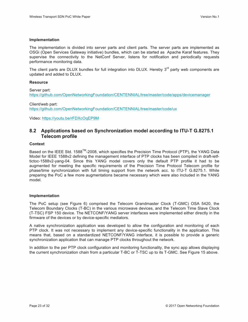
The PTP topology displays the PTP clocks and when selecting a clock the PTP path to the Grandmaster clock is highlighted.
Figure 15 – PTP topology with a highlighted path form one PTP Clock to its Grandmaster clock
Wireless Transport SDN PoC White Paper Version No.1
Page 23 of 32 © 2017 Open Networking Foundation
Implementation
The implementation is divided into server parts and client parts. The server parts are implemented as OSGi (Open Services Gateway initiative) bundles, which can be started as Apache Karaf features. They supervise the connectivity to the NetConf Server, listens for notification and periodically requests performance monitoring data.
The client parts are DLUX bundles for full integration into DLUX. Hereby 3rd party web components are updated and added to DLUX.
Resource
Server part: https://github.com/OpenNetworkingFoundation/CENTENNIAL/tree/master/code/apps/devicemanager Client/web part: https://github.com/OpenNetworkingFoundation/CENTENNIAL/tree/master/code/ux Video: https://youtu.be/rFDXcOqEP9M
8.2 Applications based on Synchronization model according to ITU-T G.8275.1 Telecom profile
Context
Based on the IEEE Std. 1588TM-2008, which specifies the Precision Time Protocol (PTP), the YANG Data Model for IEEE 1588v2 defining the management interface of PTP clocks has been compiled in draft-ietf-tictoc-1588v2-yang-04. Since this YANG model covers only the default PTP profile it had to be augmented for meeting the specific requirements of the Precision Time Protocol Telecom profile for phase/time synchronization with full timing support from the network acc. to ITU-T G.8275.1. While preparing the PoC a few more augmentations became necessary which were also included in the YANG model.
Implementation
The PoC setup (see Figure 6) comprised the Telecom Grandmaster Clock (T-GMC) OSA 5420, the Telecom Boundary Clocks (T-BC) in the various microwave devices, and the Telecom Time Slave Clock (T-TSC) FSP 150 device. The NETCONF/YANG server interfaces were implemented either directly in the firmware of the devices or by device-specific mediators.
A native synchronization application was developed to allow the configuration and monitoring of each PTP clock. It was not necessary to implement any device-specific functionality in the application. This means that, based on a standardized NETCONF/YANG interface, it is possible to provide a generic synchronization application that can manage PTP clocks throughout the network.
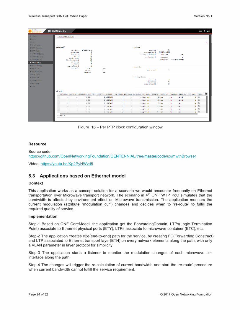
In addition to the per PTP clock configuration and monitoring functionality, the sync app allows displaying the current synchronization chain from a particular T-BC or T-TSC up to its T-GMC. See Figure 15 above.
Wireless Transport SDN PoC White Paper Version No.1
Page 24 of 32 © 2017 Open Networking Foundation
Figure 16 – Per PTP clock configuration window
Resource
Source code: https://github.com/OpenNetworkingFoundation/CENTENNIAL/tree/master/code/ux/mwtnBrowser
Video: https://youtu.be/Kp2PyHWvd5
8.3 Applications based on Ethernet model Context
This application works as a concept solution for a scenario we would encounter frequently on Ethernet transportation over Microwave transport network. The scenario in 4th ONF WTP PoC simulates that the bandwidth is affected by environment effect on Microwave transmission. The application monitors the current modulation (attribute “modulation_cur”) changes and decides when to “re-route” to fulfill the required quality of service.
Implementation
Step-1 Based on ONF CoreModel, the application get the ForwardingDomain, LTPs(Logic Termination Point) associate to Ethernet physical ports (ETY), LTPs associate to microwave container (ETC), etc.
Step-2 The application creates e2e(end-to-end) path for the service, by creating FC(Forwarding Construct) and LTP associated to Ethernet transport layer(ETH) on every network elements along the path, with only a VLAN parameter in layer protocol for simplicity.
Step-3 The application starts a listener to monitor the modulation changes of each microwave air-interface along the path.
Step-4 The changes will trigger the re-calculation of current bandwidth and start the ‘re-route’ procedure when current bandwidth cannot fulfill the service requirement.
Wireless Transport SDN PoC White Paper Version No.1
Page 25 of 32 © 2017 Open Networking Foundation
Step-5 The ‘re-route’ process involves deleting the old e2e(end-to-end) service and creating new e2e(end-to-end) service on the selected new path.
Resource
Additional information about how to install and use the application, and the source files are available at https://github.com/OpenNetworkingFoundation/CENTENNIAL/tree/master/code/apps/route
Video: https://youtu.be/xO2Z7Jn6vs0
8.4 Product simulator Context
For the preparation of the 4th ONF WTP PoC, as well as for being able to execute the applications even after the PoC ended, without having the need to maintain the physical topology, consisting of expensive Wireless Transport network equipment, an emulator was developed. Its purpose is to facilitate the development and testing of SDN applications, by eliminating the need of owning real, expensive network elements. The simulator that was developed is based on the Default Values Mediator (DVM), which was used in the previous two PoCs and is called Wireless Transport Emulator (WTE).
Implementation
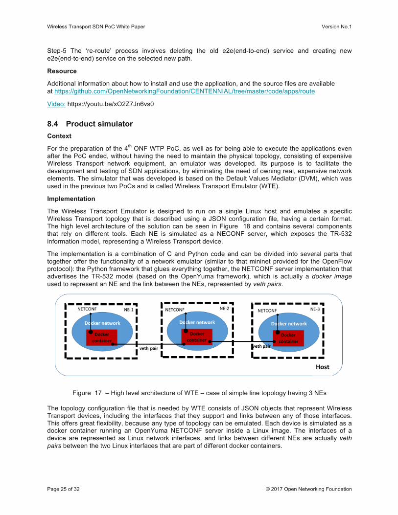
The Wireless Transport Emulator is designed to run on a single Linux host and emulates a specific Wireless Transport topology that is described using a JSON configuration file, having a certain format. The high level architecture of the solution can be seen in Figure 18 and contains several components that rely on different tools. Each NE is simulated as a NECONF server, which exposes the TR-532 information model, representing a Wireless Transport device.
The implementation is a combination of C and Python code and can be divided into several parts that together offer the functionality of a network emulator (similar to that mininet provided for the OpenFlow protocol): the Python framework that glues everything together, the NETCONF server implementation that advertises the TR-532 model (based on the OpenYuma framework), which is actually a docker image used to represent an NE and the link between the NEs, represented by veth pairs.
Figure 17 – High level architecture of WTE – case of simple line topology having 3 NEs
The topology configuration file that is needed by WTE consists of JSON objects that represent Wireless Transport devices, including the interfaces that they support and links between any of those interfaces. This offers great flexibility, because any type of topology can be emulated. Each device is simulated as a docker container running an OpenYuma NETCONF server inside a Linux image. The interfaces of a device are represented as Linux network interfaces, and links between different NEs are actually veth pairs between the two Linux interfaces that are part of different docker containers.
Wireless Transport SDN PoC White Paper Version No.1
Page 26 of 32 © 2017 Open Networking Foundation
Each simulated NE registers itself automatically to the SDN controller and exposes the Microwave Information Model. ODL can then use this model to read or write values for the attributes in that model. Some parameters are only read from a file and their values do not have a meaning to the WTE (e.g., the transmitter frequency – tx-frequency). Other attributes have their value bound to the emulation environment. For example, if ODL modifies the modulation of a certain interface, the characteristics of the link associated to that interface are changed (e.g., delay on link, link bandwidth), making WTE very powerful and capable of running even use cases that involve transmitting traffic between devices.
WTE proved to be an important tool in the context of the 4th ONF WTP PoC. It enabled SDN application developers to implement their applications and test them without need to own Wireless Transport devices. Of course some integration tests need to be done between the applications and real mediators/NEs, because an emulator cannot anticipate every situation that might arise. It is also an important tool after the PoC has ended, because it allows one to still demonstrate the proposed use cases, even if the physical topology is no longer available in the PoC test room.
Resource
WTE is part of the MeLaCon project. Details about installation and usage guidelines can be found in GitHub: https://github.com/Melacon/WirelessTransportEmulator
8.5 Power Control application for Ethernet transport Context
The application shall be capable of data throughput prediction of MW links based on the performance statistics, and accordingly tune the transmission power and modulation level of MW devices in order to match MW link capacity with current data throughput, resulting in savings of consumed energy. MW links usually work on the highest possible modulation level all the time. Assuming the same path loss, higher modulation level requires higher transmit power in comparison with lower modulation level. On the other hand, lower modulation level requiring lower transmission power results in lower data throughput.
The application should make the decision based on a combination of the following inputs:
• Stored historical performance statistics - data throughput vs. time • Current performance data (e.g. buffer occupancy) • Current MW link capacity (e.g. impacted by the weather conditions – adaptive modulation) • Time and date
Wireless Transport SDN PoC White Paper Version No.1
Page 27 of 32 © 2017 Open Networking Foundation
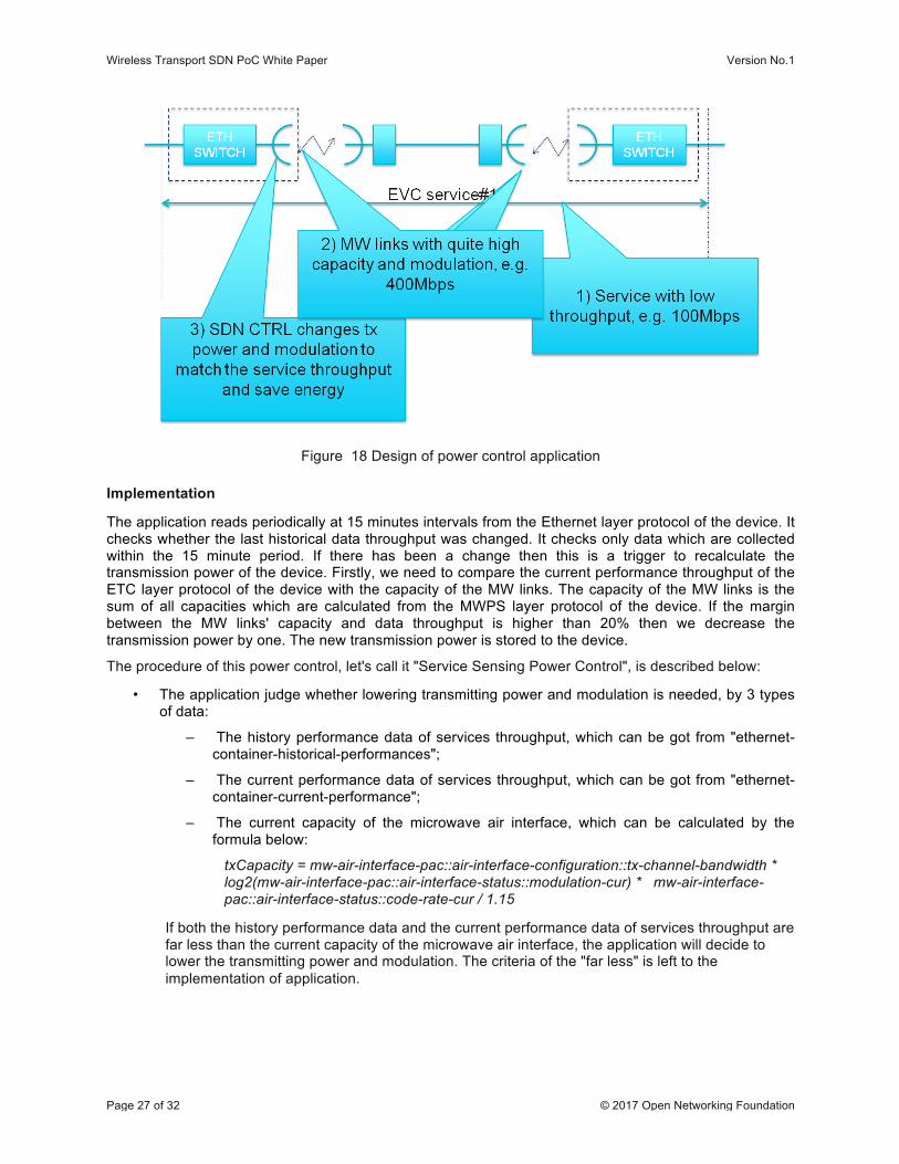
Figure 18 Design of power control application
Implementation
The application reads periodically at 15 minutes intervals from the Ethernet layer protocol of the device. It checks whether the last historical data throughput was changed. It checks only data which are collected within the 15 minute period. If there has been a change then this is a trigger to recalculate the transmission power of the device. Firstly, we need to compare the current performance throughput of the ETC layer protocol of the device with the capacity of the MW links. The capacity of the MW links is the sum of all capacities which are calculated from the MWPS layer protocol of the device. If the margin between the MW links' capacity and data throughput is higher than 20% then we decrease the transmission power by one. The new transmission power is stored to the device.
The procedure of this power control, let's call it "Service Sensing Power Control", is described below:
• The application judge whether lowering transmitting power and modulation is needed, by 3 types of data:
– The history performance data of services throughput, which can be got from "ethernet-container-historical-performances";
– The current performance data of services throughput, which can be got from "ethernet-container-current-performance";
– The current capacity of the microwave air interface, which can be calculated by the formula below:
txCapacity = mw-air-interface-pac::air-interface-configuration::tx-channel-bandwidth * log2(mw-air-interface-pac::air-interface-status::modulation-cur) * mw-air-interface-pac::air-interface-status::code-rate-cur / 1.15
If both the history performance data and the current performance data of services throughput are far less than the current capacity of the microwave air interface, the application will decide to lower the transmitting power and modulation. The criteria of the "far less" is left to the implementation of application.
Wireless Transport SDN PoC White Paper Version No.1
Page 28 of 32 © 2017 Open Networking Foundation
• The application calculate the target transmitting power, modulation and code rate, by 6 attributes below:
– transmission mode channel-bandwidth mw-air-interface-pac::air-interface-capability::supported-channel-plan-list::transmission-mode-list::channel-bandwidth
– transmission mode modulation-scheme mw-air-interface-pac::air-interface-capability::supported-channel-plan-list::transmission-mode-list::modulation-scheme
– transmission mode code-rate mw-air-interface-pac::air-interface-capability::supported-channel-plan-list::transmission-mode-list::code-rate
– configuration tx-channel-bandwidth mw-air-interface-pac::air-interface-configuration::tx-channel-bandwidth
– remote air interface's rx-threshold mw-air-interface-pac::air-interface-capability::supported-channel-plan-list::transmission-mode-list::rx-threshold
– remote air interface's rx-level-cur mw-air-interface-pac::air-interface-status::rx-level-cur
By calculate the capacity of each transmission mode whose channel bandwidth matching the configuration tx-channel-bandwidth, by formula:
txCapacity = mw-air-interface-pac::air-interface-configuration::tx-channel-bandwidth * log2(mw-air-interface-pac::air-interface-capability::supported-channel-plan-list::transmission-mode-list::modulation-scheme) * mw-air-interface-pac::air-interface-capability::supported-channel-plan-list::transmission-mode-list::code-rate / 1.15
the application decide the target modulation and code rate, which hold current services fitly, actually target "mw-air-interface-pac::air-interface-capability::supported-channel-plan-list::transmission-mode-list::modulation-scheme" and "mw-air-interface-pac::air-interface-capability::supported-channel-plan-list::transmission-mode-list::code-rate".
• By getting the remote air interface's rx-threshold corresponding to the target modulation and code rate, the application tune the transmitting power, until the remote air interface's rx-level-cur fulfil the remote air interface's rx-threshold(the margin between rx-level-cur and rx-threshold is left to the implementation of application)
• Viceversa, the application tune up the transmitting power and modulation, when the current link capacity at the risk that cannot hold the current services.
Resource
Additional information about the Power Control application, how to install it, and the source files, are available at the Github [CENTEN]. .
8.6 Mediator for microwave products Context
In previous ONF WTP PoCs most of the vendors had implemented a C++ version of a mediator for later integration in the devices (native NetConf/YANG). However, there are microwave devices in the field which will never be updated with new software version or which do not have hardware capabilities to host a NetConf server.
For such cases a Java version of a mediator was implemented, which can be integrated in an OSGi based controller platform (OpenDaylight, ONOS).
Wireless Transport SDN PoC White Paper Version No.1
Page 29 of 32 © 2017 Open Networking Foundation
Implementation
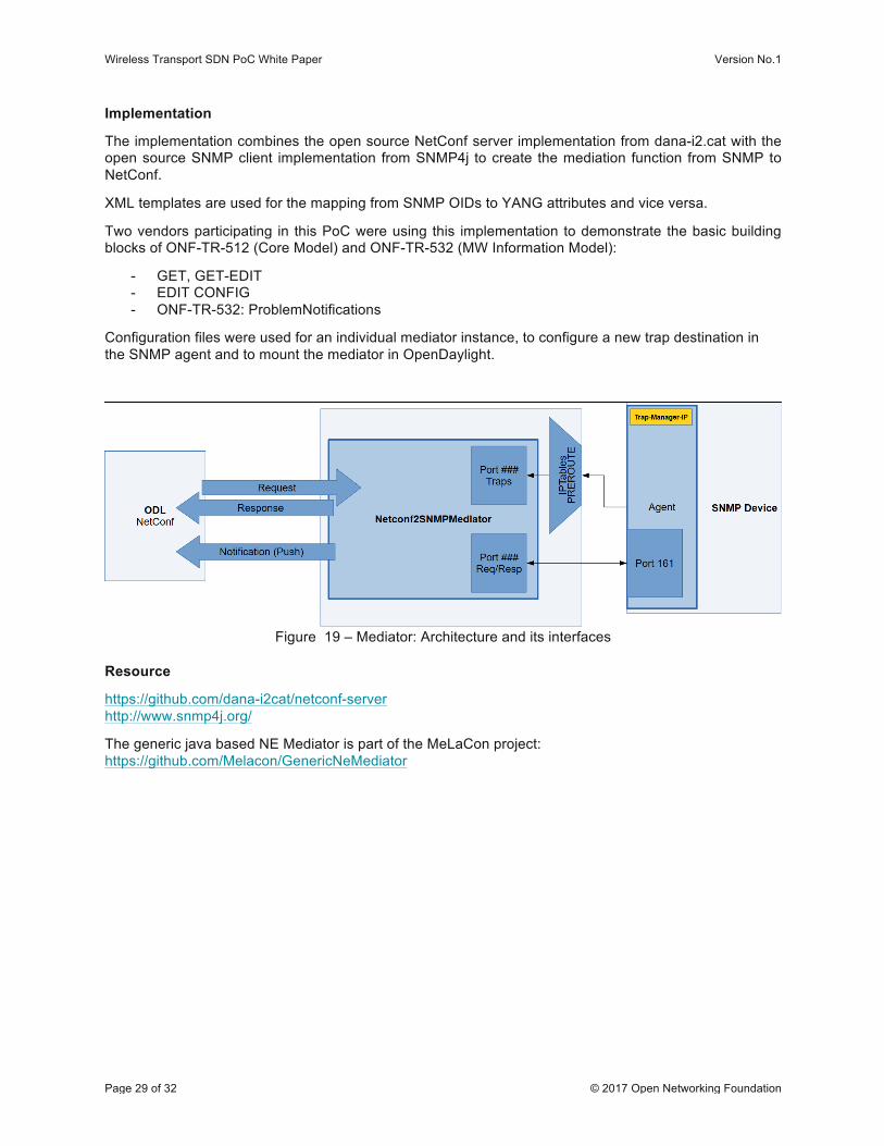
The implementation combines the open source NetConf server implementation from dana-i2.cat with the open source SNMP client implementation from SNMP4j to create the mediation function from SNMP to NetConf.
XML templates are used for the mapping from SNMP OIDs to YANG attributes and vice versa.
Two vendors participating in this PoC were using this implementation to demonstrate the basic building blocks of ONF-TR-512 (Core Model) and ONF-TR-532 (MW Information Model):
- GET, GET-EDIT - EDIT CONFIG - ONF-TR-532: ProblemNotifications
Configuration files were used for an individual mediator instance, to configure a new trap destination in the SNMP agent and to mount the mediator in OpenDaylight.
Figure 19 – Mediator: Architecture and its interfaces
Resource
https://github.com/dana-i2cat/netconf-server http://www.snmp4j.org/
The generic java based NE Mediator is part of the MeLaCon project: https://github.com/Melacon/GenericNeMediator
Wireless Transport SDN PoC White Paper Version No.1
Page 30 of 32 © 2017 Open Networking Foundation
9 References
[IEEE1588v2] “IEEE Standard for a Precision Clock Synchronization Protocol for Networked Measurement and Control Systems”, available at https://standards.ieee.org/findstds/standard/1588-2008.html
[CENTEN] GitHUB CENTENNIAL available at https://github.com/OpenNetworkingFoundation/CENTENNIAL
[G8275.1] “Precision time protocol telecom profile for phase/time synchronization with full timing support from the network”, available at https://www.itu.int/rec/T-REC-G.8275.1/en
[TR532] “Microwave Information Model, v1.0, 2016-12”, available at https://www.opennetworking.org/images/stories/downloads/sdn-resources/technical-reports/TR-532-Microwave-Information-Model-V1.pdf
[WP_3PoC] “Third Wireless Transport SDN Proof of Concept White Paper, 2016-12”, available at https://www.opennetworking.org/images/stories/downloads/sdn-resources/technical-reports/Third-Wireless-Transport-SDN-Proof-of-Concept-White-Paper.pdf
[WP_1PoC] “Wireless Transport SDN PoC White Paper, v1.0, 2015-10-09”, available at https://www.opennetworking.org/images/stories/downloads/sdn-resources/white-papers/ONF_Microwave_SDN_PoC_White_Paper%20v1.0.pdf
[WP_2PoC] “Wireless Transport SDN Proof of Concept 2 Detailed Report, v1.0, 2016-06-06”, available at https://www.opennetworking.org/images/stories/downloads/sdn-resources/technical-reports/Wireless_Transport_SDN_PoC_White_Paper.pdf
[ONF_Core] ONF Core Model 1.2 (TR-512) https://www.opennetworking.org/images/stories/downloads/sdn-resources/technical-reports/TR-512_CIM_(CoreModel)_1.2.zip[UML_Tool] UML to Yang Conversion
[UML_Tool] UML2YANG 2.0 – UML to Yang mapping tool, available at https://github.com/OpenNetworkingFoundation/EAGLE-Open-Model-Profile-and-Tools/tree/ToolChain/UmlYangTools
Wireless Transport SDN PoC White Paper Version No.1
Page 31 of 32 © 2017 Open Networking Foundation
10 Terminology API Application Programming Interface
CoS Class of Service
CVID Customer VLAN ID
CVLAN Customer VLAN
CSES Consecutive Severely Errored Seconds
DVM Default Values Mediator
ETH Ethernet MAC Layer
ETY Ethernet Physical Layer
EVC Ethernet Virtual Circuit/Connection
ES Errored Seconds
FC Forwarding Construct (as defined in ONF CoreModel)
GBA Guaranteed Bandwidth Available
GNSS Global Navigation Satellite System
GPS Global Positioning System
IDU In Door Unit
LP Layer Protocol (as defined in ONF CoreModel)
LTP Logical Termination Point
MWPS MicroWave Physical Section
NBI Northbound Interface
NE Network Element (= device under test)
Netconf Network Configuration Protocol
NFV Network Function Virtualisation
OAM Operation, Administration and Maintenance
ODL OpenDaylight
ONF Open Networking Foundation
ONOS Open Network Operating System
OSGi Open Services Gateway initiative
OTWG Open Transport Working Group
PoC Proof of Concept
PTP Precision Time Protocol
QoS Quality of Service
SBI Southbound Interface

Wireless Transport SDN PoC White Paper Version No.1
Page 32 of 32 © 2017 Open Networking Foundation
SDN Software Defined Networking
SES Severely Error Seconds
SNMP Simple Network Management Protocol
SVLAN Service/Provided VLAN
T-BC Telecom Boundary Clock
T-GM Telecom Grandmaster Clock
T-TSC Telecom Time Slave Clock
TR Technical Recommendation
UML Unified Modelling Language
VLAN Virtual Local Area Network
WTE Wireless Transport Emulator
WTP Wireless Transport Project
XML Extensible Markup Language
END OF DOCUMENT