50 disassembly and assembly engine and cooling system · 2017-11-03 · 50 disassembly and assembly...
TRANSCRIPT
50 Disassembly and assemblyEngine and cooling system
• When an angle tightening tool is not usedPut a mark on cylinder head and bolt byusing a felt pen and retighten the bolt to90 ± 5 deg.
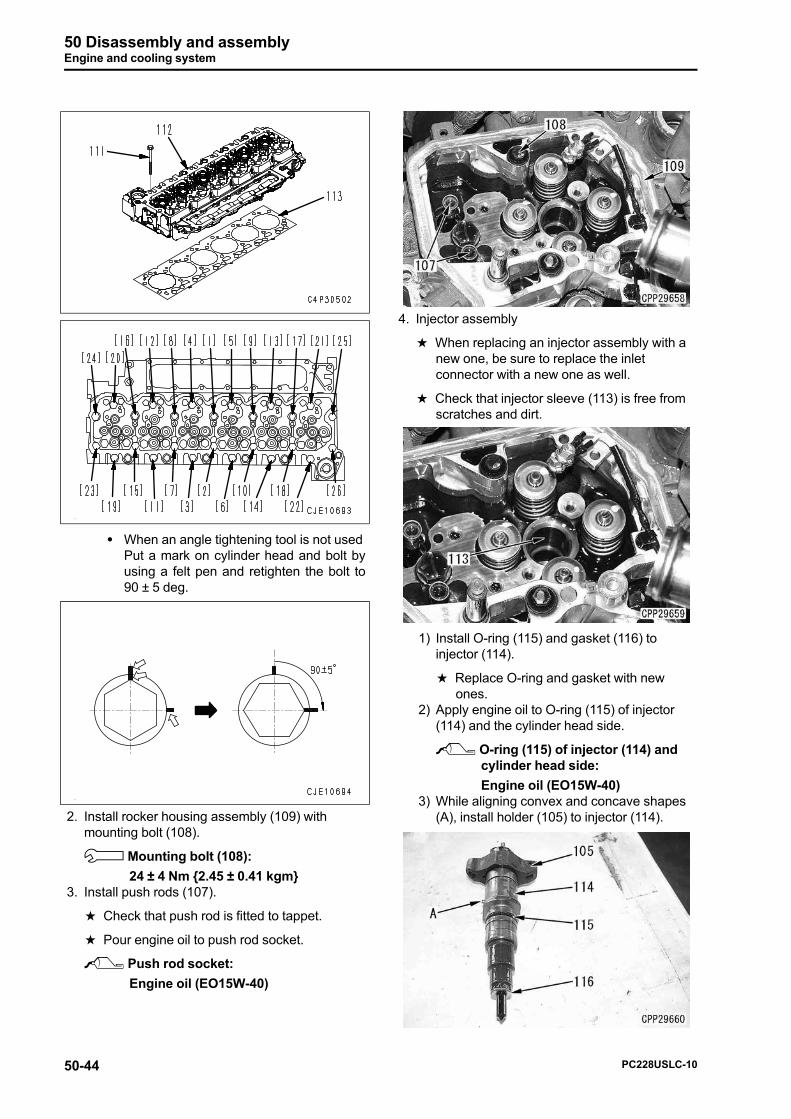
2. Install rocker housing assembly (109) withmounting bolt (108).
3 Mounting bolt (108):
24 ± 4 Nm {2.45 ± 0.41 kgm}3. Install push rods (107).
a Check that push rod is fitted to tappet.
a Pour engine oil to push rod socket.
2 Push rod socket:
Engine oil (EO15W-40)
4. Injector assembly
a When replacing an injector assembly with anew one, be sure to replace the inletconnector with a new one as well.
a Check that injector sleeve (113) is free fromscratches and dirt.
1) Install O-ring (115) and gasket (116) toinjector (114).
a Replace O-ring and gasket with newones.
2) Apply engine oil to O-ring (115) of injector(114) and the cylinder head side.
2 O-ring (115) of injector (114) andcylinder head side:
Engine oil (EO15W-40)3) While aligning convex and concave shapes
(A), install holder (105) to injector (114).
50-44 PC228USLC-10
50 Disassembly and assemblyEngine and cooling system
4) Direct fuel inlet hole of injector assembly(106) toward air intake manifold, and install itto the cylinder head.
5) Tighten holder mounting bolt (104) by 3 to 4threads.
6) Check inlet connector on the following points.If any abnormality is found, replace it.
1] When burrs or wear are found on front-end part (a) or rear-end part (b) of inletconnector
2] When foreign matters are found in theedge filter at rear-end (c) of the inletconnector
3] When cracks or deterioration are foundon the O-ring of inlet connector upper part(d).
4] When wear or uneven contact are foundon seat surface (e) at tip-end of the inletconnector.
a If high-pressure fuel leaks through theinlet connector, seat surface has finestreaks or cracks.
7) Apply engine oil to O-ring (part C) and headside (part B) of inlet connector (103).
2 O-ring of inlet connector andcylinder head side:
Engine oil (EO15W-40)8) Insert inlet connector (103) to injector (106),
and tighten retaining nut (102) lightly.
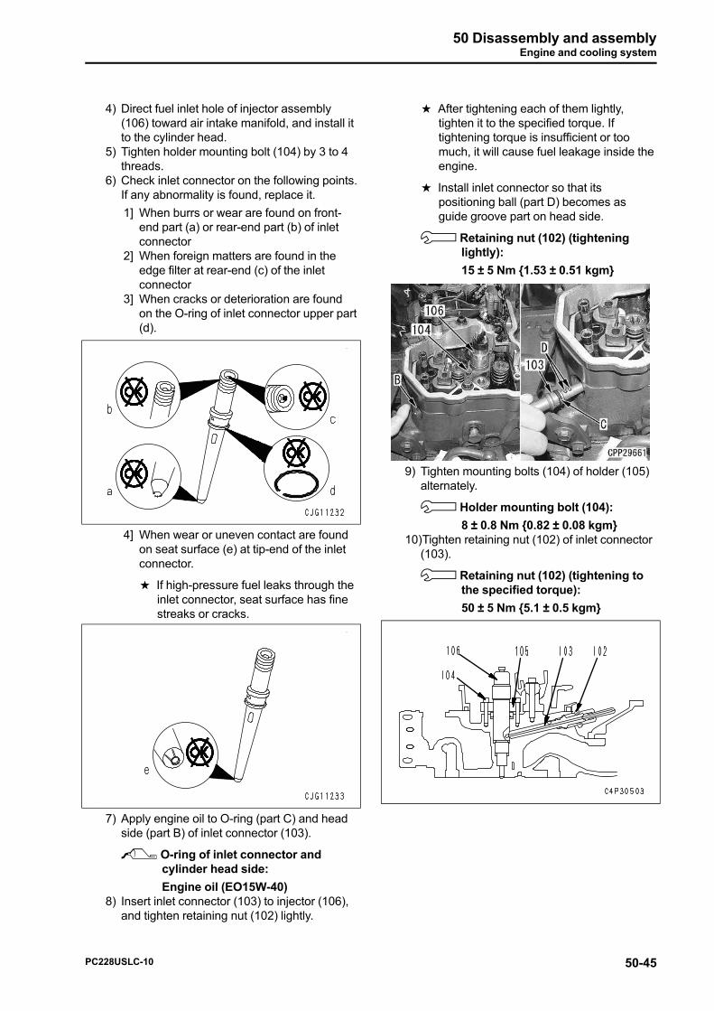
a After tightening each of them lightly,tighten it to the specified torque. Iftightening torque is insufficient or toomuch, it will cause fuel leakage inside theengine.
a Install inlet connector so that itspositioning ball (part D) becomes asguide groove part on head side.
3 Retaining nut (102) (tighteninglightly):
15 ± 5 Nm {1.53 ± 0.51 kgm}
9) Tighten mounting bolts (104) of holder (105)alternately.
3 Holder mounting bolt (104):
8 ± 0.8 Nm {0.82 ± 0.08 kgm}10)Tighten retaining nut (102) of inlet connector
(103).
3 Retaining nut (102) (tightening tothe specified torque):
50 ± 5 Nm {5.1 ± 0.5 kgm}
PC228USLC-10 50-45

50 Disassembly and assemblyEngine and cooling system
5. Rocker arm and crosshead assembly
1) Install rocker arm assembly (98), crosshead(99), and the rocker arm support.
a Shape of hole in (a) and (b) portions ofcrosshead is not identical. So whenreusing them for the same intake orexhaust valve, be sure to install them inthe same direction.
a Check that spherical part of adjustmentscrew (101) is fitted securely to socket ofpush rod, and then tighten mounting bolt(97).
3 Mounting bolt (97):
36 ± 5 Nm {3.7 ± 0.5 kgm}2) Adjust the valve clearance.
a See Testing and adjusting, "Testing andadjusting valve clearance".
a Rotate crankshaft to adjust valveclearance of each cylinder by using toolA3.
3) After adjusting the valve clearance, checkthat lock nut (100) is tightened to thespecified torque.
3 Lock nut (100):
24 ± 4 Nm {2.45 ± 0.41 kgm}4) Install harness mounting nuts (95) to injector
assembly (106).
a Check that wiring harness does notinterfere with rocker arm.
a Wiring harness mounting position
Color of wiringharness
Cylinder No.
White 1, 3, 5
Black 2, 4, 6
3 Mounting nut:
1.5 ± 0.25 Nm {0.15 ± 0.03 kgm}
a If the injector wiring harness connector(96) is removed, apply liquid gasket to O-ring part (117) and flange surface (118) ofconnector when installing.
As for O-ring, apply liquid gasket f3 mmin diameter until O-ring groove iscompletely hidden.
When O-ring is damaged, replace anentire wiring harness assembly.
2 O-ring part and flange surface ofconnector:
Liquid gasket (LG-7)
3 Connector flange mounting bolt(119):
10 ± 2 Nm {1 ± 0.2 kgm}
6. Head cover
50-46 PC228USLC-10

50 Disassembly and assemblyEngine and cooling system
1) Install gasket, and install head cover (94)with mounting nut (93).
3 Mounting nut (93):
24 ± 4 Nm {2.45 ± 0.41 kgm}2) Install blowby duct (92).
3 Mounting bolt:
7 ± 2 Nm {0.7 ± 0.2 kgm}3) Install spill tube (91).
3 Joint bolt:
24 ± 4 Nm {2.45 ± 0.41 kgm}
7. Fuel high-pressure pipe
kDo not bend the fuel high-pressure pipeto correct before installing.
kBe sure to use the genuine fuel high-pressure pipe clamp and strictly observethe specified tightening torque.
k Install each fuel high-pressure pipe andwiring harness at least 10 mm apart fromeach other.
a A fuel high-pressure pipe must be replaced ifdents such as slits (b) or spots (c) arevisually recognizable in taper seal portion (a)(in 2 mm area from tip part) of its connection,or if level difference in portion (d) (2 mm fromtip part) due to fatigue is large enough tocatch your fingers because such fuel high-pressure pipe can induce fuel leakage.
1) Lightly tighten common rail (125) and fuelhigh-pressure pipes (34) to (39).
3 Mounting bolt and sleeve nut(lightly tightening):
0.2 to 0.8 Nm {0.02 to 0.08 kgm}2) Fasten fuel high-pressure pipes (34) to (39)
to the specified torque according to thefollowing procedure.
1] Fuel high-pressure pipe ((34): Connectorside)o ((35): Connector side)o ((36):Connector side)o ((34): Common railside)o ((35): Common rail side)o ((36):Common rail side)
2] Fuel high-pressure pipe ((37): Connectorside)o ((38): Connector side)o ((39):Connector side)o ((37): Common railside)o ((38): Common rail side)o ((39):Common rail side)
3 Sleeve nut:
35 ± 3.5 Nm {3.57 ± 0.36 kgm}3) Lightly tighten fuel high-pressure pipe (40)
and tube clamp.4) Tighten fuel high-pressure pipe (40) in the
order of supply pump sideo common railside.
3 Sleeve nut:
35 ± 3.5 Nm {3.57 ± 0.36 kgm}5) Tighten common rail (125) with the bolts (4
pieces).
a Apply liquid gasket to threaded part ofbolts (P) (2 pieces) inside engine.
2 Threaded part of bolt (P):
Liquid gasket (LG-7)
3 Mounting bolt:
24 ± 4 Nm {2.45 ± 0.41 kgm}6) Fasten clamp to the specified torque.
3 Mounting bolt:
24 ± 4 Nm {2.45 ± 0.41 kgm}7) Install fuel spray prevention cap (41).
PC228USLC-10 50-47

50 Disassembly and assemblyEngine and cooling system
kWhen installing the fuel spray preventioncaps, direct their slits outward ordownward.
8. EGR cooler, exhaust manifold
1) Install bracket (90).
3 Mounting bolt:
24 ± 4 Nm {2.45 ± 0.41 kgm}2) Lightly tighten EGR cooler (86b) to bracket
(90).
a After tightening exhaust manifold lightly,tighten EGR cooler to the specifiedtorque.
3) Install bottom side tube of EGR cooler (89).
3 Mounting bolt:
9.5 ± 2 Nm {0.97 ± 0.2 kgm}
3 Hose clamp:
5 ± 1 Nm {0.5 ± 0.1 kgm}
4) Install new gasket to exhaust manifold (87a).Then install the exhaust manifold to thecylinder head and EGR cooler (86b). Tightenexhaust manifold with mounting bolts (86a)and (87b).
a Adjust the cylinder head, exhaustmanifold, and EGR cooler by looseningand tightening the mounting bolts so thatthere is no phase shift or play in them.
5) Tighten exhaust manifold mounting bolts(87b) to the specified torque in the ordershown in the figure.
3 Mounting bolt:
1] Tighten bolts in the order of [1] to [12] asshown in the figure to 53 ± 5 Nm {5.4 ±0.5 kgm}.
2] Retighten bolts [1] to [4] shown in thefigure to 53 ± 5 Nm {5.4 ± 0.5 kgm}.
6) Tighten mounting bolt (86a) to the specifiedtorque.
3 Mounting bolt:
43 ± 6 Nm {4.4 ± 0.6 kgm}7) Tighten EGR cooler (86b) to bracket to the
specified torque.
3 Mounting bolt:
24 ± 4 Nm {2.45 ± 0.41 kgm}8) Install tube (88).
3 Joint bolt:
12 ± 2 Nm {1.2 ± 0.2 kgm}
3 Sleeve nut:
15 ± 1 Nm {1.5 ± 0.1 kgm}9) Install tube (85).
3 Sleeve nut (sensor bracket side):
24.5 ± 9.8 Nm {2.5 ± 1.0 kgm}
3 Sleeve nut (exhaust manifoldside):
18 ± 3 Nm {1.8 ± 0.3 kgm}
50-48 PC228USLC-10

50 Disassembly and assemblyEngine and cooling system
10)Install tube (64).
3 Hose clamp (84):
5 ± 1 Nm {0.5 ± 0.1 kgm}
3 Tube mounting bolt:
9.5 ± 2 Nm {0.96 ± 0.2 kgm}11)Install tube clamp (83).
3 Mounting nut:
9.5 ± 2 Nm {0.96 ± 0.2 kgm}
9. Alternator
1) Install exhaust manifold pressure sensorconnector (EXHASTPRESSURE)(82).
2) Install alternator (78).
3 Mounting bolt (bracket side):
43 ± 6 Nm {4.4 ± 0.6 kgm}
3 Mounting bolt (plate side):
24 ± 4 Nm {2.45 ± 0.41 kgm}3) Install terminal B (79) and connector E12
(80) to alternator (78).
3 Terminal B (79):
5.9 to 9.8 Nm {0.6 to 1.0 kgm}4) Install wiring harness clamp (81).
5) Install fan belt (75).
1] Set tool A13 and tool A14.2] Install set tool A13 and tool A14 to A part
(width across flats: 12.7 mm) of tensionerassembly (76).
3] Install fan belt (75) as rotating tool A14 inthe opposite direction (e) to the winding-up direction.
kDo not attach a pipe to use tool A14.(The pipe may come off when you turnit, and that is very dangerous.)
kBefore turning tool A14, check thattool A14 and tool A13 are connectedsecurely and part (a) of tool A13 is setsecurely to part A of tensionerassembly (76). (If you install tool A13and tool A14 halfway and turn them,they come off, and that is verydangerous since the spring oftensioner assembly (76) is strong.)
kAfter installing fan belt (75), slowly andcarefully restore tensioner assembly(76).
kBe careful not to get your fingerscaught between the pulley and fan belt(75) during work.
PC228USLC-10 50-49

50 Disassembly and assemblyEngine and cooling system
6) Install air conditioner compressor belt (120).
a See Testing and adjusting, "Testing andadjusting air conditioner compressor belttension".
10.KVGT
1) Install gasket and install tube (69) to EGRcooler side.
3 Mounting bolt:
24 ± 4 Nm {2.45 ± 0.41 kgm}2) Install the tube clamp of tube (69) to bracket.
3 Mounting bolt:
43 ± 6 Nm {4.4 ± 0.6 kgm}3) Install heat insulation plate (68).
3 Mounting bolt:
24 ± 4 Nm {2.45 ± 0.41 kgm}4) Install bracket (67).
5) Install new gasket, and install KVGT (66).
4 KVGT (66):
25 kg
3 Mounting nut:
43 ± 6 Nm {4.4 ± 0.6 kgm}6) Install new gasket, and install KVGT return
tube (65).
3 Hose clamp:
5 ± 1 Nm {0.5 ± 0.1 kgm}
3 Mounting bolt:
24 ± 4 Nm {2.45 ± 0.41 kgm}
7) Install tube (64).
a KVGTside is tightened together. Becareful about narrow working range.
50-50 PC228USLC-10
50 Disassembly and assemblyEngine and cooling system
3 Sleeve nut:
24 ± 4 Nm {2.45 ± 0.41 kgm}8) Install tube (63).
a KVGTside is tightened together.
3 Sleeve nut:
24 ± 4 Nm {2.45 ± 0.41 kgm}9) Install tube (62) to KVGT.
a KVGTside is tightened together.
a Install eye joint (121) which is tightenedwith tube (62) so that its mounting anglebecomes 15 deg. ± 5 deg.
3 Joint bolt:
24 ± 4 Nm {2.45 ± 0.41 kgm}
10)Install tube (61).
3 V-Clamp:
7 ± 1.1 Nm {0.7 ± 0.11 kgm}
• MIKALOR clamp
a Be sure to use a new clamp.
1] Align hose to its original position(marked position).
a Reference
Air horse insertion depth: 50 mm(aftercooler side)
Air hose insertion depth: 40 mm(KVGTside)
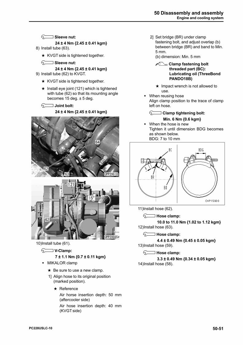
2] Set bridge (BR) under clampfastening bolt, and adjust overlap (b)between bridge (BR) and band to Min.5 mm.(b) dimension: Min. 5 mm
2 Clamp fastening boltthreaded part (BC):Lubricating oil (ThreeBondPANDO18B)
a Impact wrench is not allowed touse.
• When reusing hoseAlign clamp position to the trace of clampleft on hose.
3 Clamp tightening bolt:
Min. 6 Nm {0.6 kgm}• When the hose is new
Tighten it until dimension BDG becomesas shown below.BDG: 7 to 10 mm
11)Install hose (62).
3 Hose clamp:
10.0 to 11.0 Nm {1.02 to 1.12 kgm}12)Install hose (63).
3 Hose clamp:
4.4 ± 0.49 Nm {0.45 ± 0.05 kgm}13)Install hose (59).
3 Hose clamp:
3.3 ± 0.49 Nm {0.34 ± 0.05 kgm}14)Install hose (58).
PC228USLC-10 50-51
50 Disassembly and assemblyEngine and cooling system
15)Install the tube (57) with V-clamp by usingtool A12 (long socket).
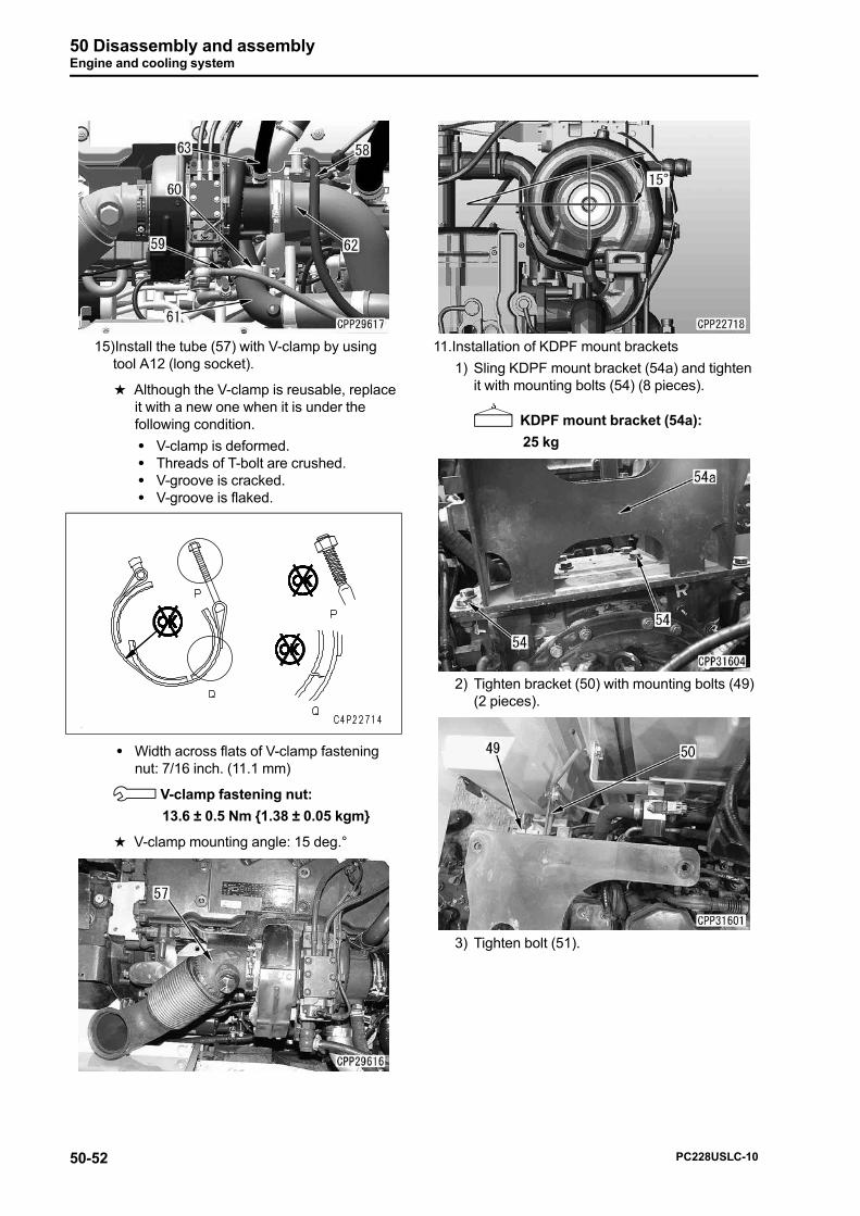
a Although the V-clamp is reusable, replaceit with a new one when it is under thefollowing condition.
• V-clamp is deformed.• Threads of T-bolt are crushed.• V-groove is cracked.• V-groove is flaked.
• Width across flats of V-clamp fasteningnut: 7/16 inch. (11.1 mm)
3 V-clamp fastening nut:
13.6 ± 0.5 Nm {1.38 ± 0.05 kgm}
a V-clamp mounting angle: 15 deg.°
11.Installation of KDPF mount brackets
1) Sling KDPF mount bracket (54a) and tightenit with mounting bolts (54) (8 pieces).
4 KDPF mount bracket (54a):
25 kg
2) Tighten bracket (50) with mounting bolts (49)(2 pieces).
3) Tighten bolt (51).
50-52 PC228USLC-10
50 Disassembly and assemblyEngine and cooling system
4) Tighten bracket (53) with mounting bolts (52)(2 pieces).
12.Install KDPF assembly (122). For details, see"Removal and installation of KDPF assembly".
13.EGR valve
1) Install gasket (123).
a When installing gasket, be careful aboutdirection of part number tag.
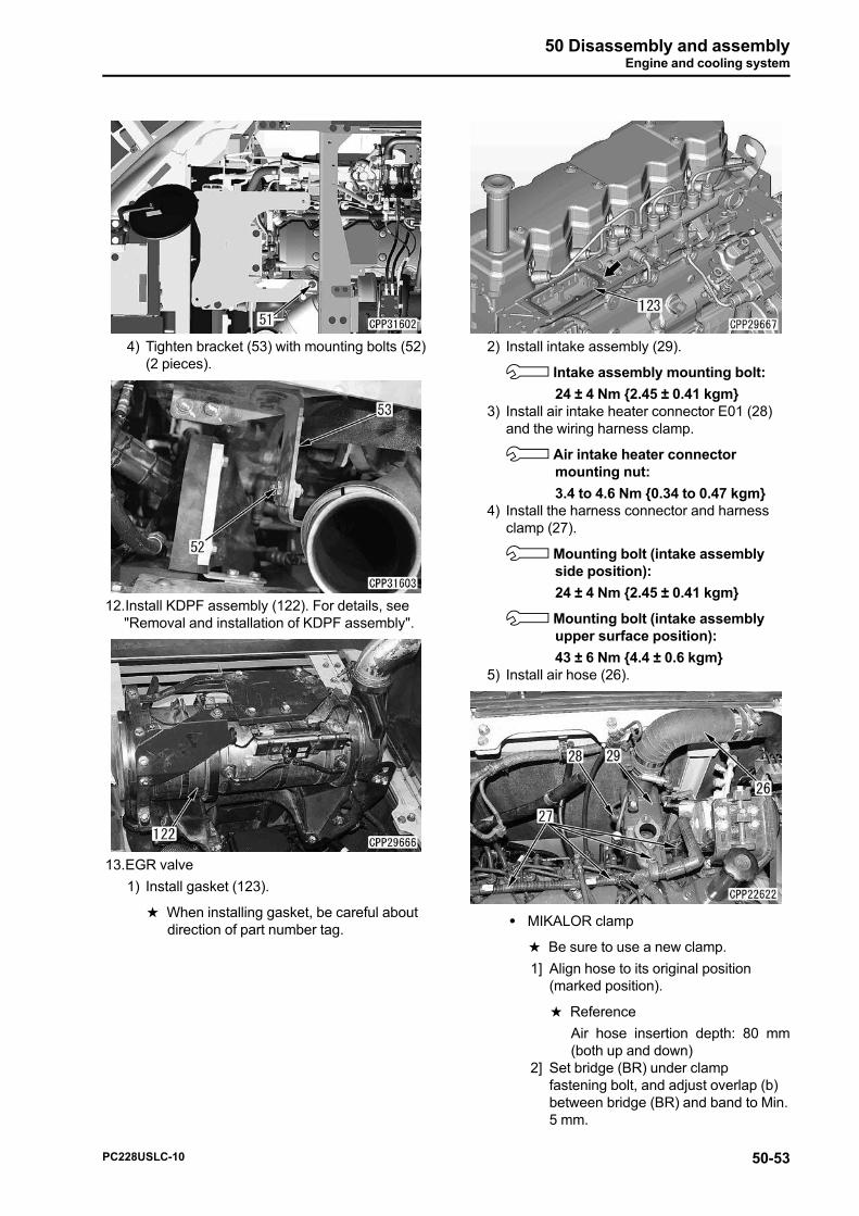
2) Install intake assembly (29).
3 Intake assembly mounting bolt:
24 ± 4 Nm {2.45 ± 0.41 kgm}3) Install air intake heater connector E01 (28)
and the wiring harness clamp.
3 Air intake heater connectormounting nut:
3.4 to 4.6 Nm {0.34 to 0.47 kgm}4) Install the harness connector and harness
clamp (27).
3 Mounting bolt (intake assemblyside position):
24 ± 4 Nm {2.45 ± 0.41 kgm}
3 Mounting bolt (intake assemblyupper surface position):
43 ± 6 Nm {4.4 ± 0.6 kgm}5) Install air hose (26).
• MIKALOR clamp
a Be sure to use a new clamp.
1] Align hose to its original position(marked position).
a Reference
Air hose insertion depth: 80 mm(both up and down)
2] Set bridge (BR) under clampfastening bolt, and adjust overlap (b)between bridge (BR) and band to Min.5 mm.
PC228USLC-10 50-53