505 digital control for steam turbines - dsf … digital governor for single/split-range actuators...
TRANSCRIPT

Product Manual 26839V1(Revision NEW, 2/2015)
Original Instructions
505 Digital Control for Steam Turbines
8200-1300, 8200-1301, 8200-1302
Manual 26839 consists of 2 volumes (26839V1 & 26839V2).
Volume 1

General Precautions
Read this entire manual and all other publications pertaining to the work to be performed before installing, operating, or servicing this equipment.
Practice all plant and safety instructions and precautions.
Failure to follow instructions can cause personal injury and/or property damage.
Revisions
This publication may have been revised or updated since this copy was produced. To verify that you have the latest revision, check manual 26455, Customer Publication Cross Reference and Revision Status & Distribution Restrictions, on the publications page of the Woodward website:
www.woodward.com/publications The latest version of most publications is available on the publications page. If your publication is not there, please contact your customer service representative to get the latest copy.
Proper Use
Any unauthorized modifications to or use of this equipment outside its specified mechanical, electrical, or other operating limits may cause personal injury and/or property damage, including damage to the equipment. Any such unauthorized modifications: (i) constitute "misuse" and/or "negligence" within the meaning of the product warranty thereby excluding warranty coverage for any resulting damage, and (ii) invalidate product certifications or listings.
Translated Publications
If the cover of this publication states "Translation of the Original Instructions" please note:
The original source of this publication may have been updated since this translation was made. Be sure to check manual 26455, Customer Publication Cross Reference and Revision Status & Distribution Restrictions, to verify whether this translation is up to date. Out-of-date translations are marked with . Always compare with the original for technical specifications and for proper and safe installation and operation procedures.
Revisions—Changes in this publication since the last revision are indicated by a black line
alongside the text. Woodward reserves the right to update any portion of this publication at any time. Information provided by Woodward is believed to be correct and reliable. However, no responsibility is assumed by Woodward unless otherwise expressly undertaken.
Manual 26839V1 Copyright © Woodward 2015
All Rights Reserved

Manual 26839V1 505 Digital Governor for Single/Split-Range Actuators
Woodward 1
Contents
WARNINGS AND NOTICES ............................................................................ 6
ELECTROSTATIC DISCHARGE AWARENESS .................................................. 8
REGULATORY COMPLIANCE ........................................................................ 9
SAFETY SYMBOLS ..................................................................................... 11
CHAPTER 1. GENERAL INFORMATION ......................................................... 12 Introduction ........................................................................................................... 12 Controller Overview .............................................................................................. 13 Functional Block Diagrams ................................................................................... 15 505 Inputs and Outputs ........................................................................................ 16 Keypad and Display .............................................................................................. 21 Watchdog Timer/CPU Fault Control ..................................................................... 23
CHAPTER 2. HARDWARE SPECIFICATIONS ................................................. 24 Flex505 Description and Features ....................................................................... 24 Environmental Specifications ............................................................................... 25 Electromagnetic Compatibility (EMC) ................................................................... 25 Outline Drawing for Installation ............................................................................ 26 Input Power Specification ..................................................................................... 26 Visual Indicators (LED’s) & CPU Configuration.................................................... 28 Communications (Ethernet) .................................................................................. 28 Communications (CAN) ........................................................................................ 30 Communications (RS-232/RS-485) ...................................................................... 32 Communications (Service Ports) .......................................................................... 33 Hardware - Terminal Blocks & Wiring .................................................................. 34 Hardware—Speed Sensor Inputs ......................................................................... 36 Hardware—Analog Inputs (4-20 mA) ................................................................... 37 Hardware—Analog Outputs (4-20 mA) ................................................................ 38 Hardware - Actuator Outputs ................................................................................ 39 Hardware - Discrete Inputs ................................................................................... 40 Hardware - Relay Outputs .................................................................................... 41 Troubleshooting Fault Codes ............................................................................... 42 Troubleshooting & Commissioning checks .......................................................... 42
CHAPTER 3. 505 CONTROL DESCRIPTION .................................................. 45 Introduction ........................................................................................................... 45 Turbine Start Modes ............................................................................................. 45 Start Permissive ................................................................................................... 45 Open Wire Detection on MPU Speed Signals ...................................................... 46 Zero Speed Signal Override ................................................................................. 46 Manual Speed Override ........................................................................................ 46 Automatic Speed Override ................................................................................... 47 Acceleration Limiter .............................................................................................. 47 Turbine Start Mode Procedures ........................................................................... 48 Speed Control Overview ....................................................................................... 59 Speed PID Operational Modes ............................................................................. 59 Manual Demand ................................................................................................... 73 Load Rejection ...................................................................................................... 74 Feed-Forward Input .............................................................................................. 74 Cascade Control ................................................................................................... 76 Auxiliary Control ................................................................................................... 82 Remote Auxiliary Set Point ................................................................................... 86

505 Digital Governor for Single/Split-Range Actuators Manual 26839V1
2 Woodward
Contents Auxiliary 2 Control................................................................................................. 88 Valve Limiter ......................................................................................................... 88 Inlet Steam Pressure Compensation .................................................................... 89 Emergency Shutdown .......................................................................................... 90 Controlled Shutdown ............................................................................................ 91 Overspeed Test Function ..................................................................................... 92 Local/Remote Function ......................................................................................... 93 Relays ................................................................................................................... 94
CHAPTER 4. CONFIGURATION PROCEDURES .............................................. 96 Program Architecture ............................................................................................ 96 Display Modes and User Levels ........................................................................... 96 Configuring the 505 .............................................................................................. 97 Exiting the Configure Mode ................................................................................126 Valve/Actuator Calibration & Test .......................................................................133 Calibration/Stroking Procedure ...........................................................................134
CHAPTER 5. 505 OPERATION ................................................................... 136 Software Architecture .........................................................................................136 Power-Up Screen ...............................................................................................137 Control Mode Architecture ..................................................................................138 User Login Levels ...............................................................................................139 Navigation ...........................................................................................................140 Page Organization ..............................................................................................141 Overview Screen ................................................................................................143 Speed Control Screen ........................................................................................143 Valve Demand Screen ........................................................................................144 Controllers Screen ..............................................................................................145 Cascade Control Screen ....................................................................................145 Auxiliary Control Screen .....................................................................................146 Analog Input Summary Screen ...........................................................................147 Contact Input Summary Screen .........................................................................147 Analog Output Summary Screen ........................................................................148 Relay Output Summary Screen ..........................................................................149 Actuator Driver Summary Screen .......................................................................149 Starting Procedures (Start Curve Screen) ..........................................................150 Overspeed Test Function (Speed Control Screen) ............................................151 Stop Key .............................................................................................................153 Alarm Summary ..................................................................................................153 Shutdown Summary ...........................................................................................158 Speed, Cascade, and Auxiliary Dynamics Adjustments .....................................160
CHAPTER 6. COMMUNICATIONS ................................................................ 164 Modbus Communications ...................................................................................164 Port Adjustments ................................................................................................167 505 Control Modbus Addresses .........................................................................167 Specific Address Information ..............................................................................180
CHAPTER 7. PRODUCT SUPPORT AND SERVICE OPTIONS ......................... 183 Product Support Options ....................................................................................183 Product Service Options .....................................................................................183 Returning Equipment for Repair .........................................................................184 Replacement Parts .............................................................................................185 Engineering Services ..........................................................................................185 Contacting Woodward’s Support Organization ..................................................185 Technical Assistance ..........................................................................................186

Manual 26839V1 505 Digital Governor for Single/Split-Range Actuators
Woodward 3
Contents
APPENDIX A. 505 PROGRAM MODE WORKSHEETS ................................... 187
APPENDIX B. 505 MARINE XXXX-XXXX .................................................. 201
DECLARATIONS ....................................................................................... 202
The following are trademarks of Woodward, Inc.: DSLC easYgen GAP LINKnet MicroNet RTCnet Woodward The following are trademarks of their respective companies: Modbus (Schneider Automation Inc.) VxWorks (Wind River Systems, Inc.)

505 Digital Governor for Single/Split-Range Actuators Manual 26839V1
4 Woodward
Illustrations and Tables Figure 1-1. Typical Single or Dual Inlet Steam Turbine........................................ 13 Figure 1-2. Explanation of Symbols ...................................................................... 15 Figure 1-3. Single or Split-Range Turbine Configurations ................................... 16 Figure 1-4. 505 Keypad and Display .................................................................... 21 Figure 2-1. Functional Block Diagram (505D Control) ......................................... 24 Figure 2-2. 505D Outline Drawing ........................................................................ 27 Figure 2-3. Input Power Connector Pinout ........................................................... 28 Figure 2-4. Ethernet Ports #1-4 (10/100) ............................................................. 29 Figure 2-5. CAN Connector Pinout ....................................................................... 30 Figure 2-6. COM1 Serial Port (RS-232/485) ........................................................ 32 Figure 2-7. COM1 Example RS-485 wiring .......................................................... 32 Figure 2-8. CPU Service Port (3 pin, 2 mm) ......................................................... 33 Figure 2-9. 505 Back Cover Label ........................................................................ 34 Figure 2-10. Terminal Block Connectors .............................................................. 35 Figure 2-11. Speed Sensor Block Diagram .......................................................... 36 Figure 2-12. Analog Input – Self-Powered Block Diagram ................................... 37 Figure 2-13. Analog Input – Loop-Powered Block Diagram ................................. 38 Figure 2-14. Analog Output Block Diagram .......................................................... 39 Figure 2-15. Actuator Output Block Diagram ....................................................... 40 Figure 2-16. Discrete Input Block Diagram .......................................................... 40 Figure 2-17. Relay Output Block Diagram ............................................................ 41 Figure 3-1. Open Wire Detection Test .................................................................. 46 Figure 3-2. Manual Start Mode Example .............................................................. 48 Figure 3-3. Semiautomatic Start mode Example .................................................. 49 Figure 3-4. Automatic Start Mode Example ......................................................... 50 Figure 3-5. Idle/Rated Start .................................................................................. 53 Figure 3-6. Automatic Start Sequence ................................................................. 54 Figure 3-7. Speed Control Functional Diagram .................................................... 59 Figure 3-8. Speed PID Control Modes ................................................................. 61 Figure 3-9. Frequency and Unit Load Relationship .............................................. 62 Figure 3-10. Speed Relationships ........................................................................ 64 Figure 3-11. Load Sharing Logic .......................................................................... 72 Figure 3-12. Typical Anti-surge Valve and Speed Feed-Forward Logic Trend .... 76 Figure 3-13. Cascade Functional Diagram ........................................................... 77 Figure 3-14. Aux Control Overview ...................................................................... 82 Figure 3-15. Aux 2 Control Overview ................................................................... 88 Figure 4-1. Initial HOME Screen (unit not configured) ......................................... 97 Figure 4-2. Configuration Menu – Configuration Mode (Edit) .............................. 99 Figure 5-1. Software Architecture .......................................................................136 Figure 5-2. 505 Splash Screen ...........................................................................137 Figure 5-3. Boot-up to HOME Screen ................................................................138 Figure 5-4. Control Mode Architecture ...............................................................139 Figure 5-5. Mode Screen ....................................................................................139 Figure 5-6. Navigation Cross ..............................................................................140 Figure 5-7. Service Menu showing “Speed Control” IN-Focus ...........................141 Figure 5-8. Configuration Menu – Operation Mode (View only) .........................141 Figure 5-9. Configuration Menu – Configuration Mode (Edit) ............................142 Figure 5-10. Overview Screen ............................................................................143 Figure 5-11. Speed Control Screen ....................................................................143 Figure 5-12. Valve Demand Screen ...................................................................144 Figure 5-13. Controllers Screen .........................................................................145 Figure 5-14. Cascade Control Screen ................................................................145 Figure 5-15. Auxiliary Control Screen ................................................................146 Figure 5-16. Analog Input Summary Screen ......................................................147
Manual 26839V1 505 Digital Governor for Single/Split-Range Actuators
Woodward 5
Illustrations and Tables Figure 5-17. Contact Input Summary Screen ..................................................... 147 Figure 5-18. Analog Output Summary Screen ................................................... 148 Figure 5-19. Relay Output Summary Screen ..................................................... 149 Figure 5-20. Actuator Driver Summary Screen .................................................. 149 Figure 5-21. HOME Menu showing “Startup Curve” IN-Focus ........................... 150 Figure 5-22. Overspeed Test Permissives ......................................................... 151 Figure 5-23. Internal (505) Overspeed Test ....................................................... 152 Figure 5-24. External Overspeed Test ............................................................... 152 Figure 5-25. ALARM Screen .............................................................................. 154 Figure 5-26. Shutdown Summary Screen .......................................................... 158 Figure 5-27. Speed Dynamics Adjustment Screen ............................................ 160 Figure 5-28. Typical Response to Load Change ................................................ 163 Figure 6-1. ASCII/RTU Representation of 3 ....................................................... 165 Figure 6-2. Modbus Frame Definition ................................................................. 166 Table 3-1. Frequency Arm/Disarm Generator Control Modes ............................. 66 Table 3-2. On-Line/Off-Line Dynamics Selection ................................................. 67 Table 3-3. Load Sharing Logic ............................................................................. 72 Table 4-1. Mode Access by User Level ................................................................ 96 Table 4-2. Actuator Driver Limits ........................................................................ 134 Table 5-1. ALARM Messages ............................................................................ 157 Table 5-2. TRIPPED Messages ......................................................................... 159 Table 6-1. ASCII vs RTU Modbus ...................................................................... 165 Table 6-2. Modbus Function Codes ................................................................... 166 Table 6-3. Modbus Error Codes ......................................................................... 167 Table 6-4. Maximum Modbus Discrete and Analog Values ............................... 167 Table 6-5. Boolean Write Addresses .................................................................. 169 Table 6-6. Boolean Read Addresses ................................................................. 173 Table 6-7. Analog Read Addresses ................................................................... 176 Table 6-8. Analog Write Addresses .................................................................... 176 Table 6-9. Control Status .................................................................................... 177 Table 6-10. Analog Input Configuration .............................................................. 177 Table 6-11. Analog Output Configuration ........................................................... 178 Table 6-12. Relay Configuration ......................................................................... 179 Table 6-13. Contact Input Configurations ........................................................... 180

505 Digital Governor for Single/Split-Range Actuators Manual 26839V1
6 Woodward
Warnings and Notices Important Definitions
This is the safety alert symbol. It is used to alert you to potential personal injury hazards. Obey all safety messages that follow this symbol to avoid possible injury or death.
DANGER—Indicates a hazardous situation which, if not avoided, will result in death or serious injury.
WARNING—Indicates a hazardous situation which, if not avoided, could result in death or serious injury.
CAUTION—Indicates a hazardous situation which, if not avoided, could result in minor or moderate injury.
NOTICE—Indicates a hazard that could result in property damage only (including damage to the control).
IMPORTANT—Designates an operating tip or maintenance suggestion.
Overspeed / Overtemperature /
Overpressure
The engine, turbine, or other type of prime mover should be equipped with an overspeed shutdown device to protect against runaway or damage to the prime mover with possible personal injury, loss of life, or property damage.
The overspeed shutdown device must be totally independent of the prime mover control system. An overtemperature or overpressure shutdown device may also be needed for safety, as appropriate.
Personal Protective Equipment
The products described in this publication may present risks that could lead to personal injury, loss of life, or property damage. Always wear the appropriate personal protective equipment (PPE) for the job at hand. Equipment that should be considered includes but is not limited to: Eye Protection Hearing Protection Hard Hat Gloves Safety Boots Respirator
Always read the proper Material Safety Data Sheet (MSDS) for any working fluid(s) and comply with recommended safety equipment.
Start-up
Be prepared to make an emergency shutdown when starting the engine, turbine, or other type of prime mover, to protect against runaway or overspeed with possible personal injury, loss of life, or property damage.

Manual 26839V1 505 Digital Governor for Single/Split-Range Actuators
Woodward 7
IOLOCK. When a CPU or I/O module fails, watchdog logic drives it into an IOLOCK condition where all output circuits and signals are driven to a known de-energized state as described below. The System MUST be designed such that IOLOCK and power OFF states will result in a SAFE condition of the controlled device. CPU and I/O module failures will drive the module into an
IOLOCK state CPU failure will assert an IOLOCK signal to all modules and
expansion racks to drive them into an IOLOCK state. Discrete outputs / relay drivers will be non-active and de-
energized Analog and Actuator outputs will be non-active and de-
energized with zero voltage or zero current. The IOLOCK state is asserted under various conditions including CPU and I/O module watchdog failures Power Up and Power Down conditions. System reset and hardware/software initialization Entering configuration mode
NOTE: Additional watchdog details and any exceptions to these failure states are specified in the related CPU or I/O module section of the manual.
Emergency Disconnecting
Device
An emergency switch or circuit breaker shall be included in the building installation that is in close proximity to the equipment and within easy reach of the operator. The switch or circuit breaker shall be clearly marked as the disconnecting device for the equipment. The switch or circuit breaker shall not interrupt the Protective Earth (PE) conductor.
Risk of Calibration and Checkout
The calibration and checkout procedure should only be performed by authorized personnel knowledgeable of the risks posed by live electrical equipment.
Fuse Power Supply Mains
The Power Supply MAINS should be properly fused according the the NEC/CEC or Authority Having Final Jurisdiction per the Input Power Specifications.
Battery Charging Device
To prevent damage to a control system that uses an alternator or battery-charging device, make sure the charging device is turned off before disconnecting the battery from the system.

505 Digital Governor for Single/Split-Range Actuators Manual 26839V1
8 Woodward
Electrostatic Discharge Awareness
Electrostatic Precautions
Electronic controls contain static-sensitive parts. Observe the following precautions to prevent damage to these parts: Discharge body static before handling the control (with power to
the control turned off, contact a grounded surface and maintain contact while handling the control).
Avoid all plastic, vinyl, and Styrofoam (except antistatic versions) around printed circuit boards.
Do not touch the components or conductors on a printed circuit board with your hands or with conductive devices.
To prevent damage to electronic components caused by improper handling, read and observe the precautions in Woodward manual 82715, Guide for Handling and Protection of Electronic Controls, Printed Circuit Boards, and Modules.
Follow these precautions when working with or near the control. 1. Avoid the build-up of static electricity on your body by not wearing clothing
made of synthetic materials. Wear cotton or cotton-blend materials as much as possible because these do not store static electric charges as much as synthetics.
2. Do not remove the printed circuit board (PCB) from the control cabinet unless absolutely necessary. If you must remove the PCB from the control cabinet, follow these precautions:
Do not touch any part of the PCB except the edges. Do not touch the electrical conductors, the connectors, or the
components with conductive devices or with your hands. When replacing a PCB, keep the new PCB in the plastic antistatic
protective bag it comes in until you are ready to install it. Immediately after removing the old PCB from the control cabinet, place it in the antistatic protective bag.

Manual 26839V1 505 Digital Governor for Single/Split-Range Actuators
Woodward 9
Regulatory Compliance ALL COMPLIANCE LISTINGS PENDING: European Compliance for CE Marking: These listings are limited only to those units bearing the CE Marking. EMC Directive: Declared to 2004/108/EC COUNCIL DIRECTIVE of
15 Dec 2004 on the approximation of the laws of the Member States relating to electromagnetic compatibility.
ATEX – Potentially Declared to 94/9/EC COUNCIL DIRECTIVE of 23 Explosive March 1994 on the approximation of the laws of the Atmospheres Member States concerning equipment and Directive: protective systems intended for use in potentially
explosive atmospheres Zone 2, Category 3 G, Ex nA IIC T4 Gc X; IP20 Low Voltage Directive: Declared to 2006/95/EC COUNCIL DIRECTIVE of
12 December 2006 on the harmonization of the laws of Member States relating to electrical equipment designed for use within certain voltage limits.
North American Compliance: These listings are limited only to those units bearing the CSA identification. CSA: CSA Certified for Class I, Division 2, Groups A, B, C,
& D, T4 at 70 °C surrounding air temperature. For use in Canada and the United States.
CSA Certificate xxxxxx-xxxxxxx Marine Compliance [Lloyd’s Type Approval is pending]: Lloyd’s Register of LR Type Approval Test Specification No. 1, Shipping: July 2013; Environmental Categories ENV1, ENV2
and ENV3 Special Conditions for Safe Use A fixed wiring installation is required. Field wiring must be in accordance with North American Class I, Division 2 (CEC and NEC), or European Zone 2, Category 3 wiring methods as applicable, and in accordance with the Local Inspection Authority having jurisdiction. Field wiring must be suitable for at least 10 °C above ambient conditions during operation. Grounding of the 505 Digital Control is required using the PE terminal. A switch or circuit breaker shall be included in the building installation that is in close proximity to the equipment and within easy reach of the operator. The switch or circuit breaker shall be clearly marked as the disconnecting device for the equipment. The switch or circuit breaker shall not interrupt the Protective Earth (PE) conductor.

505 Digital Governor for Single/Split-Range Actuators Manual 26839V1
10 Woodward
Hazardous Locations The 505 Digital Control is suitable for use in European Zone 2, Group IIC environments when installed in an IP54 minimum rated enclosure per s EN 60079-0 and EN 60079-15. This equipment must be installed in an area or enclosure providing adequate protection against impact greater than 2 Joules and the entry of dust or water. For ATEX/IECEx the 505 Digital Control shall be installed in an enclosure that is coded Ex nA, providing a minimum IP54 ingress protection. The installer shall ensure that the maximum surrounding air temperature does not exceed the rated temperature of +70 °C at the final installation location. The 505 Digital Control shall not be installed in areas exceeding Pollution Degree 2 as defined in IEC 60664-1. The interior of the enclosure shall not be accessible in normal operation without the use of a tool.
Explosion Hazard
For ATEX/IECEx installation compliance, an ATEX/IECEx approved 505 Control shall be used with the input power limited to 18–36 Vdc. If an external power supply is used to supply the Control, it shall be IECEx approved for Class 1, Division 2 Applications.
Explosion Hazard
Due to the Hazardous Location Listings associated with this product, proper wire type and wiring practices are critical to the operation.
Explosion Hazard
ENCLOSURE REQUIREMENT— ATEX/IECEx Zone 2, Category 3G applications require the final installation location provide a minimum IP-54 ingress protection enclosure against dust and water per IEC 60529. The enclosure must meet IEC 60079-0 Design & Test Requirements.
Explosion Hazard
Do not remove covers or connect/disconnect electrical connectors unless power has been switched off and the area is known to be non-hazardous.
Explosion Hazard
Substitution of components may impair suitability for Class I, Division 2 or Zone 2.
Explosion Hazard
The external ground lugs shown on the installation drawing must be properly connected to ensure equipotential bonding. This is will reduce the risk of electrostatic discharge in an explosive atmosphere. Cleaning by hand or water spray must be performed while the area is known to be non-hazardous to prevent an electrostatic discharge in an explosive atmosphere.

Manual 26839V1 505 Digital Governor for Single/Split-Range Actuators
Woodward 11
Explosion Hazard
Do not use any test points on the power supply or control boards unless the area is known to be non-hazardous.
Risque d'explosion
Ne pas enlever les couvercles, ni raccorder / débrancher les prises électriques, sans vous en assurez auparavant que le système a bien été mis hors tension; ou que vous vous situez bien dans une zone non explosive.
Risque d'explosion
La substitution de composants peut rendre ce matériel inacceptable pour les emplacements de Classe I, Division 2 et/ou Zone 2.
Risque d'explosion
Ne pas utiliser les bornes d’essai du block d’alimentation ou des cartes de commande à moins de se trouver dans un emplacement non dangereux.
Safety Symbols

505 Digital Governor for Single/Split-Range Actuators Manual 26839V1
12 Woodward
Chapter 1. General Information
Introduction This manual describes the Woodward 505 Digital Governor for steam turbines with single or split-range actuators. Released versions are 8200-1300, 8200-1301, and 8200-1302. The option charts below show the differences between the part numbers. Volume 1 of this manual provides installation instructions, describes the control, and explains the configuration (programming) and operating procedures. Volume 2 includes notes on applying the control to specific applications, Service mode information, and 505 hardware specifications. This manual does not contain instructions for the operation of the complete turbine system. For turbine or plant operating instructions, contact the plant-equipment manufacturer. Part Number Options Part Number Power 8200-1300 LVDC (18–32 Vdc) Standard Compliance 8200-1301 AC/DC (88–132 Vac or 90–150 Vdc) Standard Compliance 8200-1302 Marine/ATEX Compliance LVDC (18–32 Vdc) General Installation and Operating Notes and Warnings This equipment is suitable for use in Class I, Division 2, Groups A, B, C, and D (Class I, Zone 2, Group IIC) or non-hazardous locations. The 505s are suitable for use in European Zone 2, Group II environments per compliance with EN60079-15, Electrical apparatus for explosive atmospheres – Type of protection ‘n’ These listings are limited only to those units bearing the certification identification. Field wiring must be stranded copper wire rated at least 75 °C for operating ambient temperatures expected to exceed 50 °C. Peripheral equipment must be suitable for the location in which it is used. Wiring must be in accordance with North American Class I, Division 2 or European Zone 2 wiring methods as applicable, and in accordance with the authority having jurisdiction. For the Marine Type approved version, the field wiring must be installed with an additional shield layer which is grounded to the enclosure. The additional shielding is beyond the standard shielding described elsewhere in the manual, and it may be made from solid or flexible metal conduit, armored cabling, or a cable with an overall shield.

Manual 26839V1 505 Digital Governor for Single/Split-Range Actuators
Woodward 13
Controller Overview General Description The 505 controller is designed to control single or dual (split range) actuator steam turbines (extraction steam turbines require the 505XT version). The 505 is field programmable which allows a single design to be used in many different control applications and reduces both cost and delivery time. It uses menu driven software to instruct site engineers on programming the control to a specific generator or mechanical drive application. The 505 can be configured to operate as a stand-alone unit or in conjunction with a plant’s Distributed Control System. The 505 control has five PID controllers that can affect the demand of the inlet steam flow into the turbine; the Speed/load PID controller, the Auxiliary PID controller, Auxiliary 2 PID controller, and the Cascade PID controller. Depending on the configuration of the 505, these PIDs interact differently with each other. Please refer to the Block diagrams listed later in this chapter to fully understand PID relationships. An additional PID is available as an isolated control loop that is optional and can be used to drive an independent Analog Output signal (that is not driving a Steam Valve) for any single loop ancillary control that may be required (such as Seal Gas, Gland Seals, or lube oil pressure loops. When using the Isolated PID Control, it is recommended to select the “Enable Readback Fault” option for the Analog Output channel configured as the Isolated PID Demand. This will trigger an alarm in the 505 if a fault of the output circuit is detected. By default, Analog Output channels are not configured to produce an alarm when the output circuit has a fault. The 505 drives one or two steam turbine throttle valves to control one turbine parameter at a time, and if desired, limit turbine operation based on other parameters. The one controlled parameter is typically speed (or load), however, the 505 could be utilized to control or limit: turbine inlet pressure or flow, exhaust (back) pressure or flow, first stage pressure, generator power output, plant import and/or export levels, compressor inlet or discharge pressure or flow, unit/plant frequency, process temperature, or any other turbine related process parameter. Refer to Volume 2 of this manual for details on applications.
Figure 1-1. Typical Single or Dual Inlet Steam Turbine

505 Digital Governor for Single/Split-Range Actuators Manual 26839V1
14 Woodward
Operator Control Panel The 505 is a field configurable steam turbine control and operator control panel (OCP) integrated into one package. A comprehensive graphical operator control panel display and keypad is located on the 505’s front panel. This display can be used to configure the 505, make On-Line program adjustments, and operate the turbine/system. Easy to follow instructions allow operators to view actual and set point values at anytime during turbine operation. Communications The 505 control can communicate directly with plant Distributed Control Systems and/or Human Machine Interface (HMI) control panels, through Modbus communication ports. One serial port support RS-232 or RS-485 communications using ASCII or RTU MODBUS transmission protocols. Two Ethernet ports are also available to communication this same information between the 505 and a plant DCS. Additional Features The 505 also provides the following features: First-Out Trip indication of Alarm and Trip events with RTC time stamp, 10 External DI trip inputs, 10 External Alarm inputs, Critical Speed Avoidance (3 speed bands), Auto Start Sequence (hot & cold starts) with Temperature Input options, Dual Speed/Load Dynamics, Zero Speed Detection, Peak Speed Indication for Overspeed trip, and Isochronous Load sharing between units (with an DSLC-2 control), Feed-forward loop, Acceleration protection at initial startup, Remote droop, Frequency dead-band. Using the 505 The 505 control has three normal operating modes, Configuration Mode, Service Mode and the Run Mode. See chapter 4 for more information about the User Levels required to enter each of these modes. Configuration Mode – This mode is used to select the options needed to configure the control to your specific turbine application. While in this mode, the control will force the hardware into IO LOCK, meaning that no outputs will be active, all Relays will be de-energized, and all Analog output signals will be at 0 current. Once the control has been configured, the Program Mode is typically not needed again, unless turbine options or operation changes. It is available to be viewed at any time. A password is required to log into this mode.
Anytime the control is in IOLOCK all Relays will be de-energized and all Analog outputs will be at 0 current. Ensure that the devices receiving these commands are fail-safe at these states.
Calibration Mode – This mode is used to calibrate, tune and adjust certain parameters either while the unit is shutdown, or during turbine run time. A password is required to log into this mode. Operation Mode - This mode is the typical state for normal operations of the control and the turbine. The Run Mode is used to operate the turbine from start-up through shutdown.

Manual 26839V1 505 Digital Governor for Single/Split-Range Actuators
Woodward 15
Functional Block Diagrams An overview of the 505 valve demands is shown in Figure 1-4. The Cascade and Auxiliary PIDs are optional controllers, and are shown in the following diagrams for PID relationship purposes only. Later in this manual, more detailed functional block diagrams will be shown in relative to each control loop PID.
Figure 1-2. Explanation of Symbols

505 Digital Governor for Single/Split-Range Actuators Manual 26839V1
16 Woodward
Figure 1-3. Single or Split-Range Turbine Configurations
(Valve Demand Overview)
505 Inputs and Outputs Control Inputs Two redundant speed inputs are configurable to accept MPUs (magnetic pickup units), proximity probes or eddy current probes. Eight programmable analog inputs can be configured as one of the following input functions: 1 ‐‐‐ Not Used ‐‐‐ 2 Remote Speed Setpoint 3 Synchronizing Input 4 Sync / Load Share 5 KW / Unit Load Input 6 Cascade Input 7 Remote Cascade Setpoint 8 Auxiliary Input 9 Remote Auxiliary Setpoint 10 Auxiliary 2 Input 11 Remote Auxiliary 2 Setpoint 12 Inlet Pressure Input 13 I/H Actuator 1 Feedback 14 I/H Actuator 2 Feedback 15 Speed Feed‐Forward 16 Remote Droop 17 Remote KW Setpoint

Manual 26839V1 505 Digital Governor for Single/Split-Range Actuators
Woodward 17
18 Exhaust Steam Pressure 19 HP Valve FDBK Position 20 HP2 Valve FDBK Position 21 Isolated PID PV 22 Remote SP for Isolated PV 23 Signal Monitoring #1 24 Signal Monitoring #2 25 Signal Monitoring #3 26 Start Temperature 1 27 Start Temperature 2 Twenty contact inputs are available. The first four are defaulted for the following functions: shutdown, reset, raise speed set point, and lower speed set point. If the control is used in a generator application, two contact inputs must be configured for use as for a generator breaker and utility tie-breaker. The rest of the additional contact inputs are available for configuration to function as various controller discrete input functions as listed below. On the front panel display there are 4 additional keys that are always available – Start/Stop/Reset and Adjust Up/Down for raising or lowering a highlighted value. 1 ‐‐‐Not Used‐‐‐ 2 Reset Command 3 Speed Raise Command 4 Speed Lower Command 5 Generator Breaker 6 Utility Tie Breaker 7 Overspeed Test 8 External Run 9 Start Permissive 1 10 Idle / Rated Command 11 Halt/Continue Auto Start 12 Override MPU Fault 13 Select On‐Line Dynamics 14 Local / Remote 15 Rmt Spd Setpt Enable 16 Sync Enable 17 Freq Control Arm/Disarm 18 Casc Setpt Raise 19 Casc Setpt Lower 20 Casc Control Enable 21 Rmt Casc Setpt Enable 22 Aux Setpt Raise 23 Aux Setpt Lower 24 Aux Control Enable 25 Rmt Aux Setpt Enable 26 Auxiliary 2 Setpoint Raise 27 Auxiliary 2 Setpoint Lower 28 Spare 28 29 Remote Auxiliary 2 Enable 30 Valve Limiter Open 31 Valve Limiter Close 32 Controlled Shutdown(STOP)

505 Digital Governor for Single/Split-Range Actuators Manual 26839V1
18 Woodward
33 External Trip 2 34 External Trip 3 35 External Trip 4 36 External Trip 5 37 External Trip 6 38 External Trip 7 39 External Trip 8 40 External Trip 9 41 External Trip 10 42 External Alarm 1 43 External Alarm 2 44 External Alarm 3 45 External Alarm 4 46 External Alarm 5 47 External Alarm 6 48 External Alarm 7 49 External Alarm 8 50 External Alarm 9 51 Spare 52 I/H Actuator 1 Fault 53 I/H Actuator 2 Fault 54 Speed Forward Enable 55 Instant Min Gov/Load Speed 56 Select Hot Start 57 Remote KW Setpoint Enable 58 Clock SYNC Pulse Contact 59 Enable Rem SP for Isolated PID 60 Isolated Controller Raise 61 Isolated Controller Lower 62 Spare 62 Control Outputs Two 4–20 mA or 20–160 mA configurable actuator outputs with linearization curves are available for use. Actuator 1 is defaulted to be the main HP inlet valve demand, but both actuator channels are configurable to be HP, HP2 (for split range) or a readout Six 4–20 mA analog outputs are available for use and each can be configured as one of the following output functions: 1 ‐‐‐ Not Used ‐‐‐
2 Actual Shaft Speed
3 Speed Reference Setpoint
4 Remote Speed Setpoint
5 Load Share Input
6 Synchronizing Input
7 Generator Load
8 Cascade Input Signal
9 Cascade Setpoint
10 Remote Cascade Setpoint

Manual 26839V1 505 Digital Governor for Single/Split-Range Actuators
Woodward 19
11 Auxiliary Input Signal
12 Auxiliary Setpoint
13 Remote Auxiliary Setpoint
14 Auxiliary 2 Input Signal
15 Auxiliary 2 Setpoint
16 Remote Auxiliary 2 Setpoint
17 Valve Limiter Setpoint
18 LSS Value
19 HP Valve Demand
20 HP2 Valve Demand
21 Inlet Pressure Input
22 I/H Actuator 1 Feedback Readout
23 I/H Actuator 2 Feedback Readout
24 Isolated PID Dmd Output
25 Isolated PID PV Input Signal
26 Isolated PID Setpoint
27 Remote Isolated PID Setpoint
28 Remote KW Setpoint
29 Exhaust Pressure Input
30 HP Valve Feedback Position
31 HP2 Valve Feedback Position
32 Signal Monitoring #1
33 Signal Monitoring #2
34 Signal Monitoring #3
35 Start Temperature 1
36 Start Temperature 2
37 Spare 37
38 Spare 38 Eight Form-C relay contact outputs are available. The first channel is dedicated to be a Trip output and can be configured for use as a complete Summary Trip or a TRIP relay output (where the External Trip inputs are not included). The other seven are configurable relays, however the second relay is defaulted to be an Alarm Summary output. Each relay can be programmed to provide a contact related to a conditional state as listed in the first list, or it can be triggered as a level-active switch as per the second list Conditional States 1 ‐‐‐ Not Used ‐‐‐ 2 Summary Shutdown 3 Summary Shutdown (Trip Relay) 4 Summary Alarm 5 All Alarms Clear 6 Control Status OK 7 Overspeed Trip 8 Overspeed Test Enabled 9 Speed PID in Control 10 Remote Speed Setpoint Enabled 11 Remote Speed Setpoint Active

505 Digital Governor for Single/Split-Range Actuators Manual 26839V1
20 Woodward
12 Underspeed Switch 13 Auto Start Sequence Halted 14 On‐Line Speed PID Dynamics Mode 15 Local Interface Mode Selected 16 Frequency Control Armed 17 Frequency Control 18 Sync Input Enabled 19 Sync / Loadshare Input Enabled 20 Loadshare Mode Active 21 Cascade Control Enabled 22 Cascade Control Active 23 Remote Cascade Setpoint Enabled 24 Remote Cascade Setpoint Active 25 Auxiliary Control Enabled 26 Auxiliary Control Active 27 Auxiliary PID in Control 28 Remote Auxiliary Setpoint Enabled 29 Remote Auxiliary Setpoint Active 30 Auxiliary 2 Control Enabled 31 Auxiliary 2 Control Active 32 Auxiliary 2 PID in Control 33 Remote Auxiliary 2 Setpoint Enabled 34 Remote Auxiliary 2 Setpoint Active 35 HP Valve Limiter in Control 36 Command from Modbus BW addresses 37 Reset Pulse (2 sec) 38 Open GEN Breaker Cmd 39 Feed‐Forward Enabled 40 Feed‐Forward Active 41 Cascade PID in Control 42 Spare 42 43 Spare 43 44 Spare 44 45 Unit OK (No SD) 46 Remote KW SP Enabled 47 Remote KW Setpoint Active 48 Manual Relay Control 49 Isolated Controller in Auto 50 Spare 50 Level activated switch using this value: 1 ‐‐‐ Not Used ‐‐‐ 2 Actual Speed 3 Speed Setpoint 4 KW Input 5 Sync/Load Share Input 6 Cascade Input 7 Cascade Setpoint 8 Auxiliary Input 9 Auxiliary Setpoint 10 Auxiliary 2 Input
Manual 26839V1 505 Digital Governor for Single/Split-Range Actuators
Woodward 21
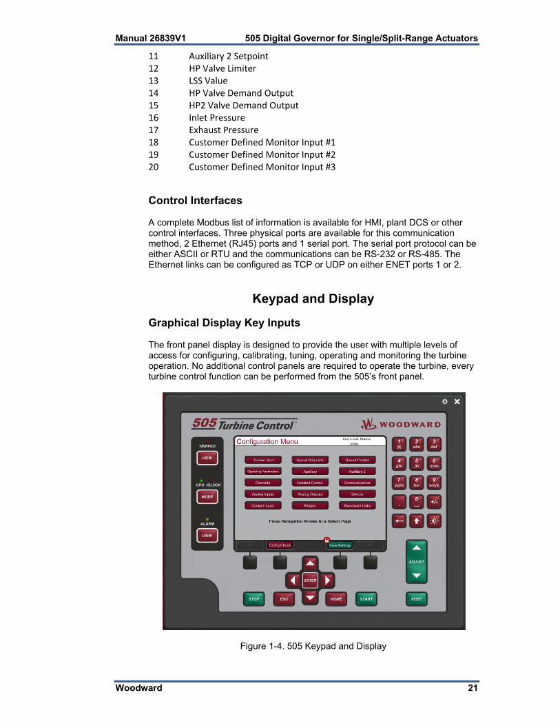
11 Auxiliary 2 Setpoint 12 HP Valve Limiter 13 LSS Value 14 HP Valve Demand Output 15 HP2 Valve Demand Output 16 Inlet Pressure 17 Exhaust Pressure 18 Customer Defined Monitor Input #1 19 Customer Defined Monitor Input #2 20 Customer Defined Monitor Input #3 Control Interfaces A complete Modbus list of information is available for HMI, plant DCS or other control interfaces. Three physical ports are available for this communication method, 2 Ethernet (RJ45) ports and 1 serial port. The serial port protocol can be either ASCII or RTU and the communications can be RS-232 or RS-485. The Ethernet links can be configured as TCP or UDP on either ENET ports 1 or 2.
Keypad and Display Graphical Display Key Inputs The front panel display is designed to provide the user with multiple levels of access for configuring, calibrating, tuning, operating and monitoring the turbine operation. No additional control panels are required to operate the turbine, every turbine control function can be performed from the 505’s front panel.
Figure 1-4. 505 Keypad and Display

505 Digital Governor for Single/Split-Range Actuators Manual 26839V1
22 Woodward
A description of each key’s function follows. Hard Key Commands NUMERIC KEYPAD = These are available for entering numeric values or text strings directly into the control when a configurable or programmable edit field has been selected. The bottom row of keys have some special features.
This is a backspace and delete (used when entering text)
In text mode this functions as a Shift key. When making analog adjustments with the ADJUST key – pressing this key at the same time as the ADJUST will invoke a ‘Fast’ rate of adjustment
Brightness key – hold this down and then use the ADJUST key to increase/decrease the screen brightness EMERGENCY TRIP KEY = This will Trip the Turbine and remove all current from the Actuator outputs (zero current). LED = Four LED’s are found on the left side – a Summary Trip, Summary Alarm, IO Lock and CPU Health. The first 2 are controlled solely by the GAP program and relate to the status of the control. The IOLOCK and CPU LED’s relate to the H/W status and are identical to these same indications on the back of the 505 VIEW buttons will jump to the Trip or Alarm Summary screen to show these events in sequence with time stamp. MODE button will jump to a Login screen that allows the user to view current permissions and allow access to changing the user login level ESC Key – this will always step the user ‘back’ one page from the current page displayed HOME Key = brings the user to the Home menu for Run, Service, or Configure. Pressing it a second time will return to the Run (Operate) Menu Home Screen NAVIGATION CROSS KEYS = These are the primary keys for navigating from page to page, or for navigation of the FOCUS on any page. Soft Key Commands – Dependent on the screen currently in view – the user must used the navigation cross keys to move the “Focus” to the desired component GREEN KEYS = Generally perform Operational Actions – such as Enabling, Disabling, Starting, Stopping, Tuning or Adjusting values MAROON KEYS = Generally perform Navigational actions that escort the user through the screen menus BLACK KEYS = Are soft-key functions that relate to the display indication above them. They can be navigational or operational. These items do not require “Focus”, they are always available on that particular screen.

Manual 26839V1 505 Digital Governor for Single/Split-Range Actuators
Woodward 23
Screen Tutorial
The 505 has a detailed Tutorial that is always accessible through the Service Menu. It provides ‘On-Screen’ help on topics such as Navigation, User Levels, Operating Modes, how to adjust parameters, and more. The User should familiarize themselves with these screens
Watchdog Timer/CPU Fault Control The IO Lock and CPU Health LED’s on the front left side of the display – are always in an identical state as the LED’s on the back side of the control. They are completely controlled by the 505 control hardware and are not controlled by the GAP application. A watchdog timer and CPU fault circuit monitors the operation of the microprocessor and microprocessor memory. If the microprocessor fails to reset the timer within 15 milliseconds of the last reset, the CPU fault-control will activate the reset output. This resets the CPU, de-energizes all relay outputs and turns off all milliamp outputs.

505 Digital Governor for Single/Split-Range Actuators Manual 26839V1
24 Woodward
Chapter 2. Hardware Specifications
Flex505 Description and Features The Flex505 controller is a significant upgrade to the existing 505 product line with enhanced CPU, Graphical display, communications, and I/O functions. Note: This controller supports expanded I/O options when using Woodward CAN distributed I/O nodes (RTCnet and LINKnet HT). Features Same installation/mounting as current 505 8.4” LCD Display (800x600) and Keypad (LV) input power: 18-36 Vdc input, isolated (HV) input power: 88-264 Vac / 90-150 Vdc, isolated Operating range of –30 °C to +70 °C (with display) Communications (4) Ethernet 10/100 communication ports, isolated (4) CAN communication ports (1 Mbit), isolated (1) RS-232/RS-485 port, isolated (1) RS-232 Service port, isolated I/O circuits GAP configurable update rates of 5 ms to 160 ms (2) Speed Sensor inputs (MPU/Prox) (with Prox Power) (8) Analog input 4-20 mA channels (with Loop Power) (6) Analog output 4-20 mA channels (2) Actuator output channels (configurable 4-20 mA/20-200 mA) (20) Discrete input channels (with Contact Power) (8) Relay outputs (form-c)
Figure 2-1. Functional Block Diagram (505D Control)

Manual 26839V1 505 Digital Governor for Single/Split-Range Actuators
Woodward 25
Environmental Specifications
Operating Temperature –30 °C to +70 °C (with display) Storage Temperature –30 °C to +70 °C (recommended 0 °C to 40 °C) Vibration 8.2 Grms, industrial skid mount, per Woodward RV1 Shock1 10 G, 3x each axis, per Woodward MS1 procedure Humidity2 5 % to 95 %, non-condensing Ingress Rating / Installation3 IP20, Pollution Degree2, Overvoltage Category 3 EMC Emissions4 EN 61000-6-4 (Heavy Industrial)
IACS UR E10 (Commercial Marine) EMC Immunity4 EN 61000-6-2 (Heavy Industrial)
IACS UR E10 (Commercial Marine) 1Limited by internal relay specification 2Cyclic condensing humidity is supported with an appropriate enclosure 3ATEX, IP-54, and Pollution Degree 3 are supported with an appropriate enclosure
using the ATEX/Marine qualified unit. 4Marine specification applies to the ATEX/Marine qualified unit
Electromagnetic Compatibility (EMC) The Flex500 product family complies with Heavy Industrial EMC requirements per EN 61000-6-4 & EN 61000-6-2 specifications. Marine Type Approval is also met per IACS UR E10 EMC test requirements when a Marine qualified version is used. Emissions EN 61000-6-4 & IACS UR E10 Radiated RF Emissions Limits 150 kHz to 5000 MHz per IEC 61000-6-4 &
Marine Type Approval. Power Line Conducted RF Emissions Limits 10 kHz to 30 MHz per IEC
61000-6-4 & Marine Type Approval. Immunity EN 61000-6-2 & IACS UR E10 Electrostatic Discharge (ESD) immunity to ±6 kV contact / ±8 kV air per IEC
61000-4-2. Radiated RF Immunity to 10 V/m from 80 MHz to 3000 MHz per IEC
61000-4-3. Electrical Fast Transients (EFT) Immunity to ±2.0 kV on I/O and Power
Supply inputs per IEC 61000-4-4. Surge Immunity on DC Power Supply inputs to ±1.0 kV line to earth and
±0.5 kV line to line per IEC 61000-4-5. Surge Immunity on AC Power Supply inputs to ±2.0 kV line to earth and
±1.0 kV line to line per IEC 61000-4-5. Surge Immunity on I/O to ±1.0 kV line to earth per IEC 61000-4-5. Conducted RF Immunity to 10 V (rms) from 150 kHz to 80 MHz per IEC
61000-4-6. Conducted Low Frequency Injection Immunity at 10% of the nominal supply
level from 50 Hz to 12 kHz on Power Inputs per Marine Type Approval test requirements.

505 Digital Governor for Single/Split-Range Actuators Manual 26839V1
26 Woodward
Outline Drawing for Installation The physical outline dimensions for the 505D control are shown below. See Woodward Reference drawing 9989-3210 for additional details if necessary.
This 505 unit has the identical mounting hole pattern as the previous version, however the holes do not come through the front of this unit; therefore mounting screws of correct length must be used.
Panel Mounting information – There are 8 x 10-32 UNF-2B tapped holes that are used to mount the 505. The holes are tapped to 0.312” min Depth. Choose the proper length screw
to not exceed this depth into the Bezel. Use screw 1069-949 (.375 Long, 10-32) for panel thickness (including
washers) .065” - .100" Use screw 1069-948 (.438 Long, 10-32) for panel thickness (including
washers) .101”- .125” Use screw 1069-946 (.500 Long, 10-32) For panel thickness (including
washers) .126” - .187”
Input Power Specification Specifications (LV) LV Input Voltage range: 18-36 Vdc Input Power (max): < 77 W, 4.3 A max Output Voltage Holdup time: > 14 ms with 24 Vdc input voltage Isolation to other circuits: > 500 Vrms to all other circuits Isolation to EARTH: > 500 Vrms to EARTH Input Overvoltage Protection: ±60 Vdc @ 25 °C Reverse Polarity Protection: 60 Vdc @ 25 °C Input Undervoltage shutdown: ~11 Vdc, non-latching Note: Breaker or power-line fusing of 8 A min is recommended to protect the power wiring network from possible wiring shorts. Specifications (HV) HV Input Voltage range: 88-264 Vac / 90-150 Vdc HV Input Frequency range: 45-65 Hz Input Power (AC max): < 73 W, 1.6 A max Input Power (DC max): < 73 W, 0.8 A max Output Voltage Holdup time: > 30 ms with 110 Vac input voltage Output Voltage Holdup time: > 120 ms with 220 Vac input voltage Isolation to other circuits: > 3000 Vrms to all other circuits Isolation to EARTH: > 1500 Vrms to EARTH Input Overvoltage Protection: ±375 Vdc @ 25 °C Reverse Polarity Protection: 375 Vdc Input Undervoltage Shutdown: ~65 Vdc, non-latching Note: Breaker or power-line fusing of 3.5 A min is recommended to protect the power wiring network from possible wiring shorts.

Manual 26839V1 505 Digital Governor for Single/Split-Range Actuators
Woodward 27
Figure 2-2. 505D Outline Drawing
505 Digital Governor for Single/Split-Range Actuators Manual 26839V1
28 Woodward
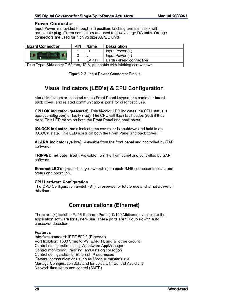
Power Connector Input Power is provided through a 3 position, latching terminal block with removable plug. Green connectors are used for low voltage DC units. Orange connectors are used for high voltage AC/DC units.
Board Connection PIN Name Description
1 L+ Input Power (+) 2 L- Input Power (–) 3 EARTH Earth / shield connection
Plug Type: Side entry 7.62 mm, 12 A, pluggable with latching screw down
Figure 2-3. Input Power Connector Pinout
Visual Indicators (LED’s) & CPU Configuration Visual indicators are located on the Front Panel keypad, the controller board, back cover, and related communications ports for diagnostic use. CPU OK indicator (green/red): This bi-color LED indicates the CPU status is operational(green) or faulty (red). The CPU will flash fault codes (red) if they exist. This LED exists on both the Front Panel and back cover. IOLOCK indicator (red): Indicate the controller is shutdown and held in an IOLOCK state. This LED exists on both the Front Panel and back cover. ALARM indicator (yellow): Viewable from the front panel and controlled by GAP software. TRIPPED indicator (red): Viewable from the front panel and controlled by GAP software. Ethernet LED's (green=link, yellow=traffic) on each RJ45 connector indicate port status and operation. CPU Hardware Configuration The CPU Configuration Switch (S1) is reserved for future use and is not active at this time.
Communications (Ethernet) There are (4) isolated RJ45 Ethernet Ports (10/100 Mbit/sec) available to the application software for system use. These ports are full duplex with auto crossover detection. Features Interface standard: IEEE 802.3 (Ethernet) Port Isolation: 1500 Vrms to PS, EARTH, and all other circuits Control configuration using Woodward AppManager Control monitoring, trending, and datalog collection Control configuration of Ethernet IP addresses General communications such as Modbus master/slave Manage Configuration data and tunables with Control Assistant Network time setup and control (SNTP)

Manual 26839V1 505 Digital Governor for Single/Split-Range Actuators
Woodward 29
Network Configuration. Ethernet ports (ETH1-4) can be configured for the customer network as desired. See the on-site Network Administrator to define an appropriate I/P address configuration.
ETHERNET CABLES—Max cable length is 100 meters. To ensure signal integrity and robust operation, double shielded (SSTP) Cat5 Ethernet cables are required for customer installations. (Woodward PN 5417-394, 10 feet)
This module has been factory configured with fixed Ethernet IP addresses of Ethernet #1 (ETH1) = 172.16.100.15, Subnet Mask = 255.255.0.0 Ethernet #2 (ETH2) = 192.168.128.20, Subnet Mask =
255.255.255.0 Ethernet #3 (ETH3) = 192.168.129.20, Subnet Mask =
255.255.255.0 Ethernet #4 (ETH4) = 192.168.130.20, Subnet Mask =
255.255.255.0
Each of the ETHERNET ports is required to be configured for a unique subnet (domain) (view default settings as an example).
Ethernet Connector (RJ45) Board Connection Description
Pin 1 – TX+ Pin 2 – TX- Pin 3 – RX+ Pin 4 – not used Pin 5 – not used Pin 6 – RX- Pin 7 – not used Pin 8 – not used SHIELD = Chassis GND
Figure 2-4. Ethernet Ports #1-4 (10/100)
Network Configuration Utility (AppManager) Woodward's AppManager software can be used to configure network setting and load Control software (GAP), HMI display software (QT), and operating system service packs. The AppManager utility can be downloaded from www.woodward.com/software. A PC connection must be made to Ethernet #1 (ETH1) using a RJ45 Ethernet cable. Note: AppManager can always be used to “discover/view” the current CPU IP Address. However, to modify settings or load applications, the PC running AppManager must be reconfigured to be on the same “network” as the CPU.

505 Digital Governor for Single/Split-Range Actuators Manual 26839V1
30 Woodward
Locate the ControlName on the module faceplate and highlight it in AppManager.
To VIEW the IP address configuration, select menu option CONTROL - CONTROL INFORMATION. Look for the Ethernet adapter addresses under the Footprint Description.
To CHANGE the IP address configuration, select menu option CONTROL - CHANGE NETWORK SETTINGS.
Communications (CAN) (4) Isolated CAN ports are available for general communications as well as simplex or redundant distributed control. Compatible devices include Woodward RTCnet nodes, LINKnet HT nodes, DVP valve products, and other 3rd party devices. Removable latching connector plugs are provided for field wiring. Network Termination: CAN networks must include a 120 Ω termination resistor at each end of the trunk line. Network Topology: Daisy chain connections between multiple devices are recommended. Any drop cable connection of a device to the trunk line should be as short as possible and much less than 6 meters. It is recommended to design the network trunk to be less than 100 meters with a max cumulative drop length of less than 39 meters. Important: For 1 Mbit/sec communication it is required that each drop cable be less than 1 meter and as short as possible. CAN Specifications Interface Standard CAN 2.0B, CANopen Network Connections (4) CAN ports, separate connectors Network Isolation 500 Vrms to EARTH, other CAN ports, all other I/O Network Speed/Length 1 Mbit @ 30 m
500 Kbit @ 100 m 250 Kbit @ 250 m (thick cable only, otherwise limited to 100 m) 125 Kbit @ 500 m (thick cable only, otherwise limited to 100 m)
Network Termination: (120 ± 10) Ω is required at each end of the network trunk line. **The termination resistor is NOT built into the hardware.
CAN Address Software configurable CAN Baud Rate Software configurable for 125 K, 500 K, 250 K, and 1 Mbit Cable / Part Number 2008-1512 (120 Ω, 3-wire, shielded twisted pair)
—Belden YR58684 or similar Cable Drops (1 Mbit) CAN Cable drops shall be < 1 m and as short as possible Cable Drops (500K, etc) CAN Cable drops shall be < 6 m and as short as possible **If needed, an isolated CAN to USB converter is IXXAT, HW221245 CAN Connectors Board Connection PIN Color Description
1 BLACK CAN Signal Ground 2 BLUE CAN Low 3 Shield CAN Shield (30 Meg + AC coupled to EARTH) 4 WHITE CAN High 5 n/a Not used, no internal connection
Plug Type: Side entry 3.5 mm, 8 A, pluggable with latching screw down Max wire size: 1.3 mm² / 16 AWG for single wires, 0.5 mm² / 20 AWG for two wires
Figure 2-5. CAN Connector Pinout

Manual 26839V1 505 Digital Governor for Single/Split-Range Actuators
Woodward 31
CAN Cable Specifications Belden YR58684 (Woodward PN 2008-1512) communications / CAN cable is approved and recommended. This is a smaller and more flexible 0.3 mm² / 22 AWG, low capacitance cable suitable for tight routing in industrial environments.
Belden YR58684, bulk cable (Woodward PN 2008-1512)
Impedance: 120 Ω 10 % at 1 MHz
DC resistance: 17.5 Ω per 1000 ft Cable capacitance: 11 pF/ft at 1 kHz
Data Pair: 0.3 mm² / 22 AWG, 7 strands, individually tinned, FEP insulation (BLUE, WHITE twisted pair)
Ground: 0.3 mm² / 22 AWG, 7 strands, individually tinned, FEP insulation (BLACK) Drain / Shield Wire: 0.3 mm² / 22 AWG, 7 strands, individually tinned
Shielding: Foil 100 % with outer Braid 65 % Jacket: FEP Insulation, BLACK
Cable type: 1.5 pair, twisted shielded Outer Diameter: 0.244 inch
Bend Radius: 2.5 inches Temperature: –70 °C to +125 °C Similar Cable: Belden 3106A (has different colors & lower temperature specs)
CAN Wiring / Shield Terminations & Limitations For robust communications performance, the CAN cabling needs to minimize the exposed, non-shielded cable section that occurs at terminal blocks. The exposed length of CAN wiring must be limited to less than 3.8 cm / 1.5 inches from the end of the shield to the terminal block. CAN shields are terminated to chassis (EARTH) through a capacitor-resistor network. This is designed into the Flex500 / 505 hardware products. However, the shield must also be directly terminated to chassis (Earth) at one point in the network. In the case of Woodward equipment, the direct ground is meant to be located at the master device end, as it exits the master device’s enclosure.
Always use shielded cables for improved communications in industrial environments. Wire terminations should expose as little un-shielded cable as possible (less than 3.8 cm / 1.5 inches).

505 Digital Governor for Single/Split-Range Actuators Manual 26839V1
32 Woodward
Communications (RS-232/RS-485) An isolated, configurable RS-232 / 485 serial port is available for customer use, as configured by the GAP software application. RS-422 communications is NOT supported. Specifications Interface standard: RS-232C and RS-485 Isolation: 500 Vrms to EARTH and all other I/O Baud Rates: 19.2K, 38.4K, 57.6K, and 115.2 K Max Distance (RS-232): 15 m (50 feet) max Max Distance (RS-485): 1220 m (4000 feet) max A shielded cable is required when using this port.
RS-485 networks require termination at both ends with approx 90–120 impedance that matches the characteristic impedance of the cable used.
Cable Note: Woodward cable 2008-1512 (3-wire) is a shielded, low capacitance 120 ohm cable that is designed for communications. This cable is also used for CAN communications.
COM1 Serial Port Connector Board Connection Description
(8 pins)
Pin 1 – RS-232 Transmit Pin 2 – RS-232 Receive Pin 3 – Signal Common Pin 4 – Shield (AC) Pin 5 – RS-485 (+) Pin 6 – Termination Resistor (+) Pin 7 – Termination Resistor (-) Pin 8 – RS-485 (-)
Plug Type: Side entry 3.5 mm, 8 A, pluggable with latching screw down Max wire size: 1.3 mm² / 16 AWG for single wires, 0.5 mm² / 20 AWG for two wires
Figure 2-6. COM1 Serial Port (RS-232/485)
Figure 2-7. COM1 Example RS-485 wiring

Manual 26839V1 505 Digital Governor for Single/Split-Range Actuators
Woodward 33
Communications (Service Ports) RS-232 Service Port An isolated RS-232 service port is located on the CPU board. Isolation is specified at 500 Vrms and baud rate is fixed at 115.2K baud, 8 data bits, no parity, 1 stop-bit, and no flow control. This port is for VxWorks operating system use only and cannot be configured for application software use. For debug use, a Woodward PN 5417-1344, USB to serial debug cable is required to attach this port to a PC. This port is to be used by trained Field Service personnel only!
Dura-Clik connector (male) Pin 1 – RS-232 Transmit Pin 2 – RS-232 Receive Pin 3 – Signal Ground
Figure 2-8. CPU Service Port (3 pin, 2 mm) USB Service Port Note: A USB service port is provided for future use, but is disabled.

505 Digital Governor for Single/Split-Range Actuators Manual 26839V1
34 Woodward
Hardware - Terminal Blocks & Wiring Back cover view with wiring label.
Figure 2-9. 505 Back Cover Label

Manual 26839V1 505 Digital Governor for Single/Split-Range Actuators
Woodward 35
Terminal Block Connectors
Figure 2-10. Terminal Block Connectors

505 Digital Governor for Single/Split-Range Actuators Manual 26839V1
36 Woodward
Hardware—Speed Sensor Inputs This controller includes (2) Digital Speed Sensor circuits that are capable of interfacing to MPU and Proximity speed probe sensors. Each channel is isolated from each other and may be configured to use with either a MPU or PROX sensor. A dedicated and isolated, PROX power (+24 V) is provided on each channel for proximity sensor use. Features (2) Digital Speed Sensor circuits, isolated individually GAP configurable for MPU sensors or Proximity sensor operation Separate terminals provided for MPU and Prox sensors Isolated Prox Power (+24 Vdc) is provided with short-circuit protection Woodward GAP block, diagnostics, and configuration support GAP configurable update rates of 5 ms to 160 ms Specifications (MPU / PROX) MPU Input Voltage: 1 to 35 Vrms MPU Input Frequency: 10 Hz to 35 KHz MPU Input Impedance: 2000 Ω, DC MPU Input Isolation: 500 Vrms to EARTH and all other I/O 500 Vrms to other MPU and PROX channels Prox Input Voltage: 0-32 VDC Prox Input Frequency: 0.04 Hz to 35 KHz (low limit depends on range) Prox Input Impedance: 2000 Ω, DC Prox Low Threshold: < 8 VDC Prox High Threshold: > 16 VDC Prox Input Isolation: 500 Vrms to EARTH and all other I/O 500 Vrms to other MPU and PROX channels. Prox Power1 output: 24 V ± 14%, 0-200 mA, short circuit & diode protected Prox Power2 output: 24 V ± 14%, 0-200 mA, short circuit & diode protected Prox Power Isolation: 500 Vrms to EARTH, all other I/O, & other Prox Power Max Speed Range: software selectable from 5 kHz to 35 kHz Accuracy (-40,70c): < ±0.025% full scale range selected Resolution: > 22 bits Speed Filter (ms): 5-10,000 ms (2 poles) Derivative Filter (ms): 5-10,000 ms (speed filter + 1 pole) Acceleration limit: 1-10,000 %/sec
Figure 2-11. Speed Sensor Block Diagram

Manual 26839V1 505 Digital Governor for Single/Split-Range Actuators
Woodward 37
Hardware—Analog Inputs (4-20 mA) AI Description and Features The Flex500 controller includes (8) 4–20 mA input channels for I/O monitoring and control. Each channel is differential (self-powered) but can be software configured for Loop Power mode. An Isolated Loop Power (+24 Vdc) is provided for analog input transducers and includes short-circuit/over-voltage protection. Features (8) 4–20 mA Analog Input Channels, 16 bit resolution Differential inputs with high common-mode voltage capability Isolated Loop Power +24 V is provided with short-circuit protection Fast AI channel #8 for special control functions Woodward GAP block, diagnostics, and configuration support GAP configurable update rates of 5 ms to 160 ms GAP configurable for Loop power operation Specifications (AI) Number of channels 8 AI Input Range 0 to 24 mA
AI Input Isolation 0 V channel to channel. 500 Vrms to EARTH and all other I/O (except USB)
AI Accuracy (@ 25 °C) ≤ 0.024 mA (0.1% of FS=24 mA) AI Accuracy (–40, +70 °C) ≤ 0.06 mA (0.25% of FS=24 mA) AI Resolution ~16 bits of full scale
AI Hardware filter 2 poles @ ~10 ms **Fast channel (ch 8) has 2 poles @ ~5 ms
AI Input Impedance 200 ohms (Rsense = 162 ohms) AI Loop power output 24 V ±14% (0-250 mA) short circuit & diode protected AI Loop power Isolation 500 Vrms to EARTH and all other I/O AI CMRR over temp > 70 dB @ 50/60 Hz (typical 86 db) AI CMVR > 200 V (dc) to EARTH AI Overvoltage ±36 V (dc) continuous at room temperature
Figure 2-12. Analog Input – Self-Powered Block Diagram

505 Digital Governor for Single/Split-Range Actuators Manual 26839V1
38 Woodward
Figure 2-13. Analog Input – Loop-Powered Block Diagram
Hardware—Analog Outputs (4-20 mA) This control provides an isolated group of (6) 4-20 mA outputs for customer use. Each output can drive up to 600 ohm loads and provides fault monitoring of individual source and return currents. Features (6) Analog Output channels (4-20 mA) Source and return current monitors Group isolated from other circuits Capable of driving higher impedance loads up to 600 ohms Woodward GAP block, diagnostics, and configuration support GAP configurable update rates of 5 ms to 160 ms Specifications (AO) Number of channels 6 (each with readback) AO Output Range 0 to 24 mA, 0 mA during shutdown
AO Output Isolation 0 V channel to channel 500 Vrms to EARTH and all other I/O
AO Accuracy (@ 25 °C) ≤ 0.024 mA (0.1% of FS=24 mA) AO Accuracy (–40, +70 °C) ≤ 0.120 mA (0.5% of FS=24 mA) AO Resolution ~14 bits of full scale AO Hardware filter (max) 3 poles @ 250 μs AO Load Capability 600 Ω at 20 mA AO Output Readbacks (0 to 24) mA, source and return AO Readback Accuracy < 3 % over full temperature range AO Readback HW Filter ~0.5 ms nominal
IOLOCK state AO circuits are driven to 0 mA during power-up, power-down, core voltage failures, and watchdog failures

Manual 26839V1 505 Digital Governor for Single/Split-Range Actuators
Woodward 39
Figure 2-14. Analog Output Block Diagram
Hardware - Actuator Outputs This control provides an isolated group of (2) Actuator outputs for customer use. Each driver can be configured for low-range (20 mA) or high-range (200 mA) operation. Fault monitoring of individual source and return currents is included. Features (2) Actuator Output channels (4-20 mA, 20-200 mA) Source and return current monitoring Group isolated from other circuits Capable of driving higher impedance loads Woodward GAP block, diagnostics, and configuration support GAP configurable update rates of 5 ms to 160 ms Specifications (ACT)
Number of channels (2) proportional drivers with source & return readbacks ACT Output Range Configurable for 24 mA or 200 mA range ACT Output Range (low) 0-24 mA, 0 mA during shutdown (FS = 24 mA) ACT Output Range (high) 0-200 mA, 0 mA during shutdown (FS = 210 mA)
ACT Output Isolation 0 V channel to channel 500 Vrms to EARTH and all other I/O
ACT Accuracy (25 °C) Low Range ≤ 0.024 mA (0.1%) High Range ≤ 0.21 mA (0.1%) ACT Accuracy (–40, +70 °C) Low Range ≤ 0.120 mA (0.5%) High Range ≤ 1.00 mA (0.5%) ACT Resolution ~14 bits of full scale ACT Hardware filter (max) 3 poles @ 500 μs ACT Load Capability (low) 600 Ω at 20 mA ACT Load Capability (high) 65 Ω at 200 mA ACT Output Readbacks (0 to 24) mA, source and return ACT Readback Accuracy < 3 % over full temperature range, (source & return) ACT Readback HW Filter ~0.5 ms nominal
ESTOP action Front panel ESTOP button will shutdown the actuator circuit and remove actuator power
IOLOCK action During IOLOCK, ACT power is shutdown and ACT circuits are driven to 0 mA during power-up, power-down, core voltage failures, and watchdog failures.
505 Digital Governor for Single/Split-Range Actuators Manual 26839V1
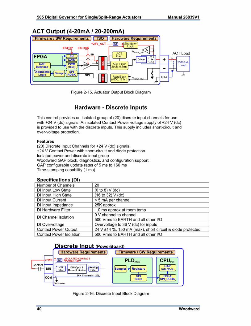
40 Woodward
Figure 2-15. Actuator Output Block Diagram
Hardware - Discrete Inputs This control provides an isolated group of (20) discrete input channels for use with +24 V (dc) signals. An isolated Contact Power voltage supply of +24 V (dc) is provided to use with the discrete inputs. This supply includes short-circuit and over-voltage protection. Features (20) Discrete Input Channels for +24 V (dc) signals +24 V Contact Power with short-circuit and diode protection Isolated power and discrete input group Woodward GAP block, diagnostics, and configuration support GAP configurable update rates of 5 ms to 160 ms Time-stamping capability (1 ms) Specifications (DI) Number of Channels 20 DI Input Low State (0 to 8) V (dc) DI Input High State (16 to 32) V (dc) DI Input Current < 5 mA per channel DI Input Impedance 25K approx DI Hardware Filter 1.0 ms approx at room temp
DI Channel Isolation 0 V channel to channel 500 Vrms to EARTH and all other I/O
DI Overvoltage Overvoltage to 36 V (dc) for inputs Contact Power Output 24 V ±14 %, 150 mA (max), short circuit & diode protected Contact Power Isolation 500 Vrms to EARTH and all other I/O
Figure 2-16. Discrete Input Block Diagram

Manual 26839V1 505 Digital Governor for Single/Split-Range Actuators
Woodward 41
Hardware - Relay Outputs This control provides (8) Isolated, Form-C Relay outputs with NO, COM, NC contacts available at the terminal block. Features (8) Relay Output Channels Each Relay Output provides NO, COM, and NC contacts Each Relay Output channel provides a coil voltage readback fault Woodward GAP block, diagnostics, and configuration support Contact isolation maintained at terminal blocks ATEX approved version available using hermetically sealed relays GAP configurable update rates of 5 ms to 160 ms Specifications (Relay outputs)
Number of channels (8) relays Contact Type Form-C with NO, COM, and NC terminals STD Relay, contacts (DC) 5 A, 5-30 Vdc (resistive) STD Relay, contacts (AC) 2 A, 115 Vac (resistive) STD Relay, operate time < 15 ms typical RELAY Coil Readback Coil voltage readback status is available RELAY Coil Rdbk Filter 1 ms approx at room temp RELAY Output Isolation 500 Vrms minimum to EARTH and all other I/O RELAY Contact Isolation 500 Vrms minimum between open contacts RELAY to RELAY Isolation 500 Vrms minimum between relays
IOLOCK State Relay outputs are de-energized during power-up, power-down, core voltage failures and watchdog failures
ATEX version: The ATEX approved control uses a Hermetically sealed relay ATX Relay, contacts (DC) 5 A, 5-30 Vdc (resistive), 0.2-0.5 A (inductive) ATX Relay, contacts (AC)** 2 A, 115 Vac (resistive), 0.1-0.2 A (inductive)
Explosion Hazard
ATEX/IECEx Compliance requires relay contact loads be < 32 Vac rms / < 32 Vdc.
Figure 2-17. Relay Output Block Diagram

505 Digital Governor for Single/Split-Range Actuators Manual 26839V1
42 Woodward
Troubleshooting Fault Codes The CPU board runs diagnostics that display troubleshooting messages through the debug Service Port and AppManager. Additional information on diagnostics tests, subsequent LED flash codes, and serial port messages is contained in the VxWorks manual. A table of the CPU fault LED flash codes is shown below:
Failure Flash CodeCPU not operational, IOLOCK state Solid Red RAM Test Failure 2, 1 FPGA Test Failure 2, 9 Watchdog not enabled 2, 10 RAM drive error 2, 11 Flash drive error 2, 12
Troubleshooting & Commissioning checks Power checks
Verify proper polarity on power connections Verify power source and wire size is sufficient for all loads Verify input power voltage is correct (i.e.: low voltage unit is 18 V to 36 Vdc) Verify PS(+) and PS(–) impedance to EARTH is > 10 MΩ
RS-232 wiring checks
Verify the RS-232 wiring uses a high quality shielded communication cable. For example, Woodward 2008-1512 (Belden YR58684) or equivalent low capacitance, shielded communications wire.
Verify the RS-232 wiring uses the signal common (COM1_GND) Verify RS-232 network length is within specifications (typically < 50 feet) Verify Signal wires (TX+,RX-) are not shorted to each other Verify Signal wires (TX+,RX-) are not shorted to COM1_GND Verify Signal wires (TX+,RX-) are not shorted to COM1_SHLD Verify Signal wires (TX+,RX-) are not connected to PS(+), PS(–), EARTH Verify COM1_GND is not connected to PS(+), PS(–), EARTH Verify the overall cable shield is terminated to EARTH at only (1) location.
RS-485 wiring checks
Verify the RS-485 wiring uses a high quality shielded communication cable. For example, Woodward 2008-1512 (Belden YR58684) or equivalent low capacitance, shielded communications wire.
Verify RS-485 network length is within spec for the baud-rate (typically < 4000 feet) Verify the network is terminated properly at both ends with approx 90–120 Verify the RS-485 wiring uses the signal common (COM1_GND) Verify Signal wires (RS-485+, RS-485–) are not shorted to each other Verify Signal wires (RS-485+, RS-485–) are not shorted to COM1_GND Verify Signal wires (RS-485+, RS-485–) are not shorted to COM1_SHLD Verify Signal wires (RS-485+, RS-485–) are not connected to PS(+), PS(–), EARTH Verify COM1_GND is not connected to PS(+), PS(–), EARTH Verify the overall cable shield is terminated to EARTH at only (1) location.

Manual 26839V1 505 Digital Governor for Single/Split-Range Actuators
Woodward 43
CAN wiring checks Verify the CAN wiring uses a high quality, 3-wire, shielded communication cable. For
example, Woodward 2008-1512 (Belden YR58684) or equivalent low capacitance, shielded communications wire.
Verify CAN network length is < max length spec for the baud rate being used Verify network is terminated properly at both ends with 120 , ±10% Verify the CAN wiring uses the signal common (CAN_GND) Verify CAN drop cables to each device are as short as possible and meets spec. Verify CANH is not connected to PS(+), PS(–), EARTH Verify CANL is not connected to PS(+), PS(–), EARTH Verify CAN_COM is not connected to PS(+), PS(–), EARTH Verify CAN_SHLD shield wire is not shorted to PS(+), PS(–) Verify the CAN overall cable shield is terminated to EARTH at only (1) location for
each network. For redundant CAN devices, verify CAN1 and CAN2 networks are not miswired and
connected together.
AI (non-loop), Analog Input wiring checks Verify that external XDCR's are NOT used with these self-powered channels. Verify each AI(+,–) is not shorted to another input channel. Verify each AI(+) terminal is not shorted to PS(+), PS(–), EARTH. Verify each AI(–) terminal is not shorted to PS(+), PS(–), EARTH. Verify each AI shield wire is not shorted to PS(+), PS(–). Verify each AI shield wire is terminated at the node properly. Functionally verify the wiring for each AI channel using a simulator source.
AI (Loop power), Analog Input wiring checks
Verify that external XDCR's are connected to these channels. Verify the LPWR voltage level (+24 V dc) is correct for the XDCR. Verify each LPWR(+) terminal is wired to the XDCR POWER(+). Verify each LPWR(+) terminal is not shorted to PS(+), PS(–), EARTH. Verify each AI(–) terminal is not shorted to PS(+), PS(–), EARTH. Verify each AI shield wire is not shorted to PS(+), PS(–). Verify each AI shield wire is terminated at the node properly. Verify that all XDCR's channels use less than 250 mA of LPWR. Functionally verify the wiring for each AI channel using a simulator source.
AO, Analog Output wiring checks
Verify each AO(+,–) is not shorted to another output channel. Verify each AO(+,–) is not shorted to another Analog Input channel. Verify each AO(+) terminal is not shorted to PS(+), PS(–), EARTH. Verify each AO(–) terminal is not shorted to PS(+), PS(–), EARTH. Verify each AO shield wire is not shorted to PS(+), PS(–). Verify each AO shield wire is terminated at the node properly. Functionally verify the wiring for each AOUT by driving 4 mA and 20 mA to the load
from the GAP application. Verify correct output current with a meter. Verify the correct SRC_RDBK & RET_RDBK values in GAP. DI, Discrete Input wiring checks
Verify each DI(+) is not shorted to another input. Verify each DI(+) is not shorted to CPWR(+), CPWR(–), PS(+), PS(–), EARTH. Verify each DI(+) wiring is functional by setting each input HIGH (>16 V DC) and then
LOW (<8 V DC). Verify GAP software detects the state change. When possible, consider using a shielded DIN cable.

505 Digital Governor for Single/Split-Range Actuators Manual 26839V1
44 Woodward
DI, Contact Power (CPWR) wiring checks CPWR(+) is an output voltage, it should never be connected to any other supply. To maintain node isolation, verify CPWR(–) is not shorted to PS(–). Using the internal isolated Contact Power output (CPWR,COM) is highly
recommended to maintain discrete input isolation for other plant devices / controls Verify CPWR(+) is not connected to CPWR(–), PS(–), EARTH. Verify CPWR(–) is not connected to CPWR(+), PS(+), EARTH. Verify CPWR voltage meets spec at the terminal block (18 to 32 V dc).
DO Relays, Relay wiring checks
Verify each Relay output (NO,C,NC) contact is connected to the load properly Verify each Relay output (NO,C,NC) is not shorted to another output channel. Verify the function of each Relay output (NC,NO) wiring by driving each output ON
then OFF. Verify the GAP software detects the readback state change. When possible, consider using shielded wiring for relay cables.
Additional wiring checks when using RTCnet/LINKnet nodes TC, Thermocouple Input wiring checks
Verify each TC(+,–) is not shorted to another input channel. Verify each TC(+) terminal is not shorted to PS(+), PS(–), EARTH. Verify each TC(–) terminal is not shorted to PS(+), PS(–), EARTH. Verify each TC shield wire is not shorted to PS(+), PS(–). Verify no wires are landed accidently on the NC, no-connect terminals. Verify each TC shield wire is terminated at the node properly. Functionally verify the wiring for each TC channel using a simulator source. TC OPENS: A TC input will read MAX DegC if the (+) or (–) wire is broken / open. TC SHORTS: A TC input will read 0 DegC if the (+) and (–) wires are shorted.
GROUND FAULTS: Input channels accidently shorted to EARTH will be more susceptible to spurious noise events related to the installation and environment.
RTD, Input wiring checks
Verify each RTD(+,–) is not shorted to another input channel. Verify each RTD(+) terminal is not shorted to PS(+), PS(–), EARTH. Verify each RTD(–) terminal is not shorted to PS(+), PS(–), EARTH. Verify each RTD(sense) terminal is not shorted to PS(+), PS(–), EARTH. Verify each RTD(sense) terminal is connected properly for 3-wire sensors. Verify each RTD(sense) terminal is jumpered to RTD(–) for 2-wire sensors. Verify each RTD shield wire is not shorted to PS(+), PS(–). Verify each RTD shield wire is terminated at the node properly. Functionally verify the wiring for each RTD channel using a simulator source. RTD OPENS: RTD channels will read MAX DegC if the (+) or (–) wire is broken.

Manual 26839V1 505 Digital Governor for Single/Split-Range Actuators
Woodward 45
Chapter 3. 505 Control Description
Introduction The 505 has five PID controllers that can affect the demand to the main inlet steam valve; the speed/load PID controller, an Acceleration PID, two Auxiliary PID controllers, and the Cascade PID controller. Depending on the configuration of the 505, these PIDs interact differently with each other. Please refer to the Block diagrams listed earlier in this manual to fully understand PID relationships.
Turbine Start Modes The 505 has three turbine start modes (manual, semi-automatic or automatic) from which to choose from. One of these start modes must be chosen and programmed to perform a system start-up. Once a ‘RUN’ command is issued, the speed set point and valve limiter are manipulated automatically by the 505 or manually by the operator, depending on which start mode is selected. After a turbine start sequenced has been completed, turbine speed will be controlled at a minimum controlling speed. The minimum controlling speed may be idle if idle/rated is being used, low idle if the auto start sequence is used, or minimum governor if neither idle/rated or auto start sequence is used. A ‘RUN’ command may be issued from the 505 keypad, an external contact, or through Modbus communications. If an ‘External Run’ contact is programmed, a ‘RUN’ command is issued when the contact is closed. If the contact is closed prior to start-up it must be opened and re-closed to issue a ‘RUN’ command. If turbine speed is sensed when a ‘RUN’ command is issued, the control will instantly match the speed set point to the sensed speed and continue towards the minimum controlling speed. In the event the sensed turbine speed is greater than the minimum controlling speed setting, the speed set point will match this sensed speed, the Speed PID will control at this point, and the control will wait for further action to be taken by the operator (unless auto start sequence is configured). If turbine speed is first sensed within a critical speed avoidance band when a ‘Run’ command is received, the speed set point will match the actual speed, decrease to the lower end of the critical avoidance band, and wait for action to be taken by the operator.
Start Permissive An external contact may be used as a turbine start-up permissive. When programmed for this functionality, the contact input must be closed in order for a ‘RUN’ command to be executed. Should the contact be open when a ‘RUN’ command is given, an alarm will be issued and the 505 display will indicate that the start permissive was not met (Start Perm Not Met). The alarm does not need to be cleared but the contact must be closed before the 505 will accept the ‘RUN’ command. After ‘RUN’ has been accepted, the start permissive contact will have no effect on operation. Example: This input could be connected to a Trip & Throttle valve’s closed limit switch to verify that it is in the closed position before a turbine start-up is performed.

505 Digital Governor for Single/Split-Range Actuators Manual 26839V1
46 Woodward
Open Wire Detection on MPU Speed Signals The 505 automatically verifies continuity of the speed MPU circuits each time it prepares to issue a “Ready to Start” status message. If an open wire is detected it will issue an alarm for this input, if all MPU’s appear to have open wires a Trip is initiated. This open wire test can be done manually any time the turbine is stopped and the speed is zero. It is also possible to Disable the automatic test at start from this screen The screen is located under Analog Inputs/Speed Signal X/Open Wire Test.
Figure 3-1. Open Wire Detection Test
Zero Speed Signal Override The 505 issues a shutdown if no speed signal is detected (magnetic pickup voltage less than 1 Vrms or speed is less than the ‘Failed Speed Level’). To allow the control to start with speed not being sensed, this shutdown logic must be overridden. The control can be configured to provide a manual or an automatic speed override. For added protection, a timed limit on the override is available. The status of the MPU override logic may be viewed in the Service mode or through Modbus communications. The override logic applies to both passive and active speed probes.
Manual Speed Override If the ‘Override MPU Fault’ function is assigned to a contact input, the loss-of- speed detection logic is overridden as long as this contact is closed; until the maximum time expires. Opening the assigned contact input, disables the override logic, and re-arms the loss-of-speed detection circuit. Once re-armed, a system shutdown is executed if the sensed speed drops below the ‘Failed Speed Level’ setting. A maximum override time limit is provided as an extra level of protection, in the event the contact input is left closed. A ten minute maximum time limit is applied to a Manual override command (as defaulted in the Service Mode). This time starts when the RUN command is initiated and re-arms the loss-of-speed detection when the time expires. The 505 will execute a system shutdown if turbine speed isn’t above the ‘Failed Speed Level’ setting when the time expires.

Manual 26839V1 505 Digital Governor for Single/Split-Range Actuators
Woodward 47
Automatic Speed Override If the Manual Speed Override option is not programmed, the Automatic Speed Override logic is used by the 505 to override the loss-of-speed signal shutdown logic during a turbine start-up. With the Automatic Override logic, the loss-of-speed signal failure is armed when the turbine trips and remains armed until the sensed turbine speed exceeds the programmed (‘Failed Speed Level’ setting + 50 rpm). Once turbine speed exceeds this level, the loss of speed detection circuit is re-armed and the control will execute a system shutdown if sensed speed drops below the ‘Failed Speed Level’ setting. For added protection, a timed limit is available on the automatic speed override function. The timed speed override timer deactivates the loss-of-speed override logic after the programmed time expires. If programmed, this timer starts counting down once a ‘START’ command has been issued. This timer when programmed provides an extra level of protection, in the event both speed input probes are failed when the unit is started. This timer may be programmed in the 505’s Service mode.
Acceleration Limiter The acceleration limiter is available for startup to significantly reduce speed overshoot to the minimum controllable speed setpoint at turbine start. The Acceleration Limiter is disabled after reaching the minimum controllable speed and the 505 will continue the start sequence via the Speed PID. If the Acceleration Limiter is set to be used via the Service menu, then it will control speed at the ‘Rate to Min’ rate (RPM/s), as set in the Turbine Start configuration, until the Speed PID is in control at the Minimum Controllable Speed. When the Start Sequence is set to “No Start Sequence”, the Minimum Controllable Speed is Minimum Governor. When the Start Sequence is set to “Idle/Rated Sequence” or “Auto Start Sequence”, the Minimum Controllable Speed is the Lowest Idle setting.
Acceleration Control
Using the Acceleration Limiter feature carries some risk without proper tuning of the Acceleration PID. Please monitor actuator behavior at turbine start. Verify there is no instability in the Acceleration Controller that may result in system damage during oscillation of the actuator/valve if it is unstable. When the response of the Acceleration Controller is over-damped, it may follow the speed setpoint very slowly at startup or even move the valve closed but, after this, acceleration should be controlled fairly well until the Acceleration Limiter logic is disabled.

505 Digital Governor for Single/Split-Range Actuators Manual 26839V1
48 Woodward
Turbine Start Mode Procedures Manual Start Mode The following start-up procedure is employed when the Manual start mode is configured: 1. Issue a RESET command (to reset all alarms and shutdowns) 2. Issue a START command (verify T&T valve is closed before issuing)
At this point the 505 will ramp open the governor valve to its maximum position at the ‘Valve Limiter Rate’.
The speed set point will ramp from zero to the minimum controlling speed setting at the ‘Rate To Min’ rate.
3. Open Trip & Throttle valve at a controlled rate When turbine speed increases to the minimum controlling speed, the
505’s Speed PID will take control of turbine speed by controlling turbine inlet valve position.
4. Open Trip & Throttle valve to 100% Speed remains controlled at the minimum controlling point until action is
taken by the operator or the ‘Auto Start Sequence’, if programmed, begins controlling.
The ‘Limiter Max Limit’, ‘Valve Limiter Rate’ and ‘Rate To Min’ settings are tunable in the Service mode.
The trip-and-throttle valve must be closed before pushing the ‘RUN’ key in Manual Start mode. If a START command is given while the trip-and-throttle valve is open, there exists a possibility of turbine runaway with resultant serious injury or loss of life.
START TIME
100%
0%
ACTUATOR
SPEED
VALVE LIMITER
COMMAND
TRIP & THROTTLEVALVE
CONTROLSPEED
Operator Must ThrottleOpen Trip & Throttle Valve
Figure 3-2. Manual Start Mode Example

Manual 26839V1 505 Digital Governor for Single/Split-Range Actuators
Woodward 49
Semiautomatic Start Mode The following start-up procedure is employed when the Semiautomatic start mode is configured: 1. Issue a RESET command (to reset all alarms and shutdowns) 2. Open the Trip & Throttle valve (verify that the turbine does not accelerate) 3. Issue a START command
At this point the speed set point will ramp from zero to the minimum controlling speed setting at the ‘Rate to Min’ rate.
4. Raise the 505’s VALVE LIMITER at a controlled rate. When turbine speed increases to the minimum controlling speed, the
505’s Speed PID will take control of turbine speed by controlling turbine inlet valve position.
5. Raise the 505’s VALVE LIMITER to 100%. Speed remains controlled at the minimum controlling point until action is
taken by the operator or the ‘AUTO START SEQUENCE’, if programmed, begins controlling.
The valve limiter will open at the ‘Valve Limiter Rate’ and may be moved using the 505 keypad, external contacts or Modbus communications. The ‘Limiter Max Limit’, ‘Valve Limiter Rate’ and ‘Rate To Min’ settings are tunable in the Service mode.
START TIME
100%
0%
ACTUATOR
SPEED
VALVE LIMITER
COMMAND
TRIP & THROTTLEVALVE
CONTROLSPEED
Operator Must ManuallyRaise Valve Limiter
Figure 3-3. Semiautomatic Start mode Example

505 Digital Governor for Single/Split-Range Actuators Manual 26839V1
50 Woodward
Automatic Start Mode The following start-up procedure is employed when the Automatic start mode is configured: 1. Issue a RESET command (to reset all alarms and shutdowns) 2. Open the Trip & Throttle valve (verify that the turbine does not accelerate) 3. Issue a START command
At this point the 505 will ramp open the governor valve to its “HP Max at Start” setting at the ‘Valve Limiter Rate’ setting.
The speed set point will ramp from zero to the minimum controlling speed setting at the ‘Rate to MIN’ rate.
When turbine speed increases and matches the ramping speed set point, the 505’s Speed PID will take control of turbine speed by controlling turbine inlet valve position.
Speed remains controlled at the minimum controlling point until action is taken by the operator or the ‘Auto Start Sequence’, if programmed, begins controlling.
Once the Speed PID begins controlling turbine speed, the HP Limiter will automatically ramp to the ‘Vlv Lmtr Max Limt’.
Optionally the ‘HP Max at Start’ and ‘Vlv Lmtr Max Limt’, ‘Valve Limiter Rate’ and ‘Rate To Min’ settings can be adjusted in the Service mode, while the turbine is in operation. The automatic start routine may be aborted at any time by issuing valve limiter raise or lower commands, or an emergency shutdown.
START TIME
100%
0%
ACTUATOR
SPEED
VALVE LIMITER
COMMAND
TRIP & THROTTLEVALVE
CONTROLSPEED
Figure 3-4. Automatic Start Mode Example
Manual 26839V1 505 Digital Governor for Single/Split-Range Actuators
Woodward 51
Critical Speed Avoidance In many turbines, it is desirable to avoid certain speeds or speed ranges (or pass through them as quickly as possible) due to excessive turbine vibration or other factors. During programming, three critical speed ranges may be configured. These bands may be any speed range that is less than the minimum governor speed setting. Within a critical speed range, the 505 moves the speed set point at the critical speed rate programmed and does not allow the speed set point to stop within the critical speed avoidance band. If the turbine is accelerating through a critical avoidance band and excessively high vibrations are experienced, selecting the speed set point lower command will bring the unit back to the lower limit of the band. The speed set point cannot be stopped in the critical band. If a Raise/Lower Speed Set point command is issued while in a critical band, the speed set point will ramp up or down (depending on raise or lower command) to the extent of the critical range. Since the lower speed set point has priority over a raise set point, issuing a lower command while increasing through the band will reverse the set point direction and return it to the lower limit of the band. If a lower speed set point command is given while in a critical band, turbine speed must reach the bottom of the band before another command can be executed. A speed set point value cannot be directly entered (with the ENTER key) within the programmed critical speed band settings. In the event this is attempted, an error message will appear on the 505 front panel display. If another controlling parameter, besides the Speed PID, drives the turbine’s speed into a critical band for longer than five seconds, the speed set point will instantly go to the idle setting and an alarm will occur (Stuck in Critical). During a start-up routine if the Speed PID cannot accelerate the unit though a programmed band within a calculated length of time, a “Stuck in Critical” alarm will be issued and the speed set point will instantly return to idle. The “calculated length of time” is a value of five times the length of time it should normally take to accelerate through the band (based on the “Critical Speed Rate” setting). If the “Stuck in Critical” alarm occurs on a regular basis, it may be indicating that the “Critical Speed Rate” is set too fast for the turbine to respond to. Critical speed bands are defined in the configure mode. All critical speed band settings must be set below the ‘Min Governor Speed Set Point’. A configure error will occur if an idle set point is programmed within a critical speed band. The rate in which the speed set point moves through a critical speed band is set by the ‘Critical Speed Rate’ setting. The ‘Critical Speed Rate’ setting should be set at but no higher than the turbine’s rated maximum acceleration rate. No Start Sequence If neither, the Idle/Rated or Auto Start Sequence functions are programmed, the speed set point will ramp from zero to the minimum governor set point at the ‘Rate To Min’ setting rate. Critical speed bands cannot be programmed with this configuration.

505 Digital Governor for Single/Split-Range Actuators Manual 26839V1
52 Woodward
Idle/Rated The idle/rated function gives an operator the ability to move between a programmed idle speed and a programmed rated speed at a configured rate. The selection of idle or rated speed set point positions can be made through the front panel keypad, through remote contact inputs, or through the Modbus communications links. The idle/rated function can also be programmed as a ramp-to-rated function only. If the 505’s Idle/Rated function is programmed, once a ‘START’ command is given, the 505 ramps turbine speed from zero to the programmed Idle setting, then waits for a command from the operator to ramp turbine speed to the “Rated Speed” setting. When deselected, the turbine speed ramps down to the application’s Idle Speed setting (as defaulted in the Service Mode). The Idle/Rated function can be used with any 505 start mode (manual, semiautomatic, automatic). When a START command is issued, the speed set point will ramp from zero rpm up to and hold at the ‘Idle Setpt’ setting. When a ramp- to-rated command is given, the speed set point ramps to the ‘Rated Setpt’ setting at the ‘Idle/Rated Rate’. While ramping to a Rated speed, the set point can be stopped by a raise or lower speed command or a valid entered speed set point. The 505 will inhibit a ramp-to-idle speed or ramp-to-rated speed command, if the Generator Breaker is closed, Remote Speed Set Point is enabled, Cascade PID is in control, or the Auxiliary PID is in control (as defaulted in the Service Mode). Alternatively, the 505’s ‘Idle Priority’ and ‘Use Ramp to Idle Function’ Service mode settings can be configured to change the defaulted idle/rated logic. Ramp to Rated Feature The Idle/Rated function can be changed to a “Ramp to Rated” function (see Service Mode). With this configuration, the speed set point holds at the idle speed setting until a Ramp-to-Rated command is given. Upon command the speed set point will accelerate to the Rated speed set point, however, it will not ramp back to the idle speed setting. When Rated is de-selected, the speed set point stops as opposed to returning to Idle. When this configuration is used, there is no Ramp- to-Idle option; it is not used. If Rated is de-selected while in a critical speed avoidance band (using Ramp to Rated only feature), the speed set point will stop at the top end of the avoidance band. If the Ramp to Rated function is stopped/halted using a raise or lower speed set point command, the set point will continue to the upper limit of the band if a Raise command was used or will reverse direction to the lower limit of the band if a Lower command was used. If Idle is selected while in a critical speed avoidance band (not using Ramp to Rated only feature), the speed set point will return to the Idle set point, continuing to move at the critical avoidance rate while within the band. The speed set point cannot be stopped within a critical speed avoidance band. Attempting to stop the ramp to rated while in a critical band will continue the speed set point to the upper limit of the band if a Raise command was used or will reverse direction to the lower limit of the band if a Lower command was used. A Ramp-to-Idle speed or Ramp-to-Rated speed command may be selected from the 505 keypad, contact input, or Modbus communications. The last command given from any of these three sources dictates the function performed.

Manual 26839V1 505 Digital Governor for Single/Split-Range Actuators
Woodward 53
If a 505 contact input is programmed to select between Idle or Rated speeds, Idle speed is selected when the contact is open and rated speed is selected when it is closed. The Idle/Rated contact can be either open or closed when a trip condition is cleared. If the contact is open, it must be closed to initiate a Ramp-to-Rated speed. If the contact is closed, it must be opened and re-closed to initiate a Ramp- to-Rated speed. When the turbine is used for mechanical drive applications, rated speed may be set at the minimum governor speed setting. When the turbine is used to drive a generator, the ‘rated speed’ setting may be set at or between the minimum governor and synchronous speed settings. All pertinent Idle/Rated parameters are available through the Modbus links, refer to Chapter 6 for a complete listing.
Figure 3-5. Idle/Rated Start
Automatic Start Sequence
This function is not the same as the ‘AUTOMATIC START MODE’. The Automatic Start Sequence can be used with any one of the three start modes.
The 505 can be configured to utilize an Automatic Start Sequence to start the turbine. This sequencing logic allows the 505 to perform a complete controlled system start-up from zero speed to rated speed. With this function, the turbine’s starting ramp rates and idle speed hold times depending on either the length of time the unit was shutdown or upon optional temperature input signals. This sequence logic may be used with any of the three start modes (manual, semiautomatic, automatic), and is initiated by a ‘RUN’ command.

505 Digital Governor for Single/Split-Range Actuators Manual 26839V1
54 Woodward
With this function, when a ‘START’ command is given, the Automatic Start Sequence ramps the speed set point to a low idle set point, holds at this setting for the set duration, ramps the speed set point to the Idle-2 setting, holds at this setting for a the set duration, ramps the speed set point to Idle-3 setting, holds at this setting for the set duration, then finally ramps the speed set point to the programmed rated turbine speed setting. All ramp rates and hold times are programmable for both hot start and cold start conditions. The control differentiates between hot and cold starts by using a “Hours-Since-Trip” timer or a contact input. When using the “Hours-Since-Trip” timer, the timer starts when a shutdown has been executed and turbine speed has decreased below the low idle speed setting.
Figure 3-6. Automatic Start Sequence
With this sequence, a set of hot-start ramp rates and hold times is programmed for use when a ‘START’ command is given and the turbine has been shutdown for less than the programmed ‘HOT START’ time setting. A set of cold-start ramp rates and hold times is also programmed for use when a ‘START’ command is given and the turbine has been shutdown for longer than the programmed ‘COLD START’ time setting. If a turbine ‘START’ command is given when the length of time the system has been shutdown is between the ‘HOT START’ and ‘COLD START’ time settings, the control can be configured to interpolate between the hot and cold programmed start values to determine starting rates and hold times.

Manual 26839V1 505 Digital Governor for Single/Split-Range Actuators
Woodward 55
For example, if the unit had the following Automatic Start Sequence settings: COLD START (> xx HRS) = 22 HRS HOT START (< xx HRS) = 2 HRS LOW IDLE SETPT = 1000 RPM LOW IDLE DELAY (COLD) = 30 MINIMUM LOW IDLE DELAY (HOT) = 10 MINIMUM USE IDLE 2 = *TRUE RATE TO IDLE 2 (COLD) = 5 RPM/S RATE TO IDLE 2 (HOT) = 15 RPM/S IDLE 2 SETPT = 1500 RPM USE IDLE 3 = *TRUE RATE TO IDLE 3 (COLD) = 5 RPM/S RATE TO IDLE 3 (HOT) = 15 RPM/S IDLE 3 SETPT = 2000 RPM IDLE 3 DELAY TIME (COLD) = 30 MINIMUM IDLE 3 DELAY TIME (HOT) = 20 MINIMUM RATE TO RATED (COLD) = 10 RPM/S RATE TO RATED (HOT) = 20 RPM/S RATED SETPT = 3400 RPM If the unit was tripped for 12 hours, the control would interpolate between the hot and cold parameters and use the following rates and delays (viewed in the Service Mode, see Volume 2): LOW IDLE DELAY = 20 MINIMUM RATE TO IDLE 2 = 10 RPM/S IDLE 2 DELAY = 10 MINIMUM RATE TO IDLE 3 = 10 RPM/S IDLE 3 DELAY = 10 MINIMUM RATE TO RATED = 15 RPM/S RST Timer Level = 3500 RPM Hot RST Timer (min) = 10 MINUTES Based on the example’s configuration and trip time, the Speed Set Point would ramp to 1000 rpm at the rate to minimum setting and hold for 20 minutes (turbine speed must also be at or above 1000 rpm), move to 1500 rpm at 10 rpm/s and hold there for 10 minutes, move to 2000 rpm at 10 rpm/s and hold there for 10 minutes and lastly, move to 3400 rpm at 15 rpm/s. At 3400 rpm, the sequence would be completed. However, speed reference must be above the HOT RESET LEVEL during
more than HOT RESET DELAY, to fully use the HOT parameter If the unit was tripped for 2 hours or less and restarted, the control would
use the hot start parameters. If the unit was tripped for 22 hours or longer and restarted, the control would use the cold start parameters.
The 505 will automatically set the hours-since-trip timer to its maximum setting of 200 hours to ensure a cold start is selected after a power up or upon exiting the Program mode. The hours-since-trip timer will reset only when the turbine speed has increased above the minimum governor speed/RST timer level setting for the Not RST timer duration.
Optionally, if a contact input is configured for the “Select Hot Start” function, then the Auto Start Sequence’s Hot start setting will be selected and used during the start routine when the respective contact is closed, and the Cold start curves will be used when the respective contact is open.

505 Digital Governor for Single/Split-Range Actuators Manual 26839V1
56 Woodward
If it is desired to have the control NOT interpolate between the Cold/Hot ramp times, then the Cold Start and Hot Start hour settings can be set equal to each other and no DI input is needed (the Cold and Hot Start hours setting is found in Configuration/Turbine Start menu). The unit will follow the Hot times below this setting and the Cold Values when this time is exceeded. Hot/Cold Start Temperature Inputs An analog input configured as a temperature signal can be used to determine whether the turbine is hot or cold for startup speed setpoint rates and idle delay times. In addition, a warm setting is also available for a total of 3 turbine temperature conditions. Cold, warm, and hot starts each have programmable speed setpoint rates for each speed level in the startup sequence, whether Idle/Rated or Automatic Start with Idle 1, Idle 2, Idle 3, and Rated speed is used. To specify cold or hot conditions for the turbine, the Hot/Cold Temperature logic will determine if the “Start Temperature 1” analog input is greater than the configured “Hot Minimum Temperature”. If so, the HOT rates and delays will be used for the startup sequence configured. If not, the COLD rates and delays will be used for the startup sequence configured. Optionally, a Warm setting is available. If “Use Warm Condition” is selected in the Turbine Start configuration menu, it provides an intermediate level between Hot and Cold rates and delay times for the start sequence. Using the Warm setting requires another temperature level to be configured. If the “Start Temperature 1” analog input is greater than the configured “Hot Minimum Temperature” then the HOT rates and delays will be used for the startup sequence configured. If the “Start Temperature 1” analog input is greater than the configured “Warm Minimum Temperature” but less than the “Hot Minimum Temperature” then the WARM rates and delays will be used for the startup sequence configured. If the temperature is below both settings, then the COLD rates and delays will be used for start sequence configured. A second temperature analog input can be used with the Hot/Warm/Cold feature as well. This requires configuring a second analog input as “Start Temperature 2” and the “Use Temperature Input 2” checkbox should be selected in the Turbine Start configuration menu. This will provide a second unique setpoint for this temperature input for both the Warm and Hot conditions. When using the second temperature analog input an option to use the temperature difference, as a condition for a Warm or Hot start, is also available. Select the “Use Temperature Difference” checkbox in the Turbine Start configuration menu. The difference between Start Temperature 1 and 2 must be less than the configured amount for Hot/Warm conditions to be met. If the “Select Hot/Cold” contact input is configured, the Hot/Cold Temperature logic will respond to this signal. If the contact is open, Cold will be selected. If the contact is closed, it allows for a Warm or Hot start if all the temperature conditions for the Warm or Hot start are satisfied. When a temperature input fails then the Hot/Warm conditions for that input will not be met, which means that the start sequence will use the Cold start values. The start will proceed normally as if the turbine is running the cold condition.

Manual 26839V1 505 Digital Governor for Single/Split-Range Actuators
Woodward 57
See the following for all conditions that are required, if configured, for a Warm or Hot start. T1 = Start Temperature 1 T2 = Start Temperature 2 Td = Difference between Start Temperature 1 and 2 CI = Select Hot/Cold Contact input Hot/Warm/Cold Start Description of Conditions
COLD HOT or WARM conditions not met or temperature input failed.
WARM T1 > Warm T1 setpoint T2 > Warm T2 setpoint Td < Warm Td Setpoint
CI closed HOT T1 > Hot T1 setpoint
T2 > Hot T2 setpoint Td < Hot Td Setpoint
CI closed Halting the Auto Start Sequence The Auto Start Sequence can be halted at any time from the 505 keypad, contact input or through Modbus. The sequence can be halted by a halt command, a raise or lower speed set point command, or when a speed set point is directly ‘Entered’ from the 505 keypad or through Modbus communications. When the sequence is halted, the delay timers do not stop if they have already started counting down. The sequence will resume when a ‘Continue’ command is issued. If there were 15 minutes remaining to hold at an idle speed and the Halt command was issued for 10 minutes before a issuing a Continue command, the sequence would remain at the idle speed for the remainder of the ‘Hold Time’—which in this example is 5 minutes.
The ‘Hold Time’ is only used if the speed setpoint exactly equals the associated Idle hold setpoint. If the speed setpoint is different from this hold point, selecting ‘Continue’ will ramp the setpoint up to the next hold point regardless of the ‘Hold Time’. Caution should be taken when raising or lowering the speed set point to ‘Halt’ the Automatic Start Sequence.
The halting and continuing of the Auto Start Sequence can be performed through the 505 keypad, contact input, or Modbus. The last command given from any of these three sources determines the mode of operation. However, a shutdown condition will disable this function, requiring it to be re-enabled after a start-up has been performed. If a 505 contact input is programmed to function as a Halt/Continue command, the sequence is halted when the contact is open, and continued when the contact is closed. The Halt contact can be either open or closed when a Reset command is given. If the contact is closed, it must be opened to allow the sequence to be halted. If the contact is open, it must be closed and reopened to issue a halt command. Alternatively, a relay can be programmed to indicate when the Auto Start Sequence is halted.

505 Digital Governor for Single/Split-Range Actuators Manual 26839V1
58 Woodward
An option is available to automatically halt the auto start sequence at the idle set points. This feature would result in the unit automatically stopping or halting at the low idle set point and at the high idle set point. If the unit is started and the speed is above the low idle set point, the sequence will initialize as halted. The sequence must be given a ‘Continue’ command once halted. The hold timers are still active with this option. If ‘Continue’ is selected and the hold timer has not expired, the sequence will remain in a timed wait until the hold timer has expired and then continue from that point. When the ‘Auto Halt at Idle Setpts’ option is programmed, the Auto Start Sequence Continue contact input only requires a momentary closure to continue the sequence. Automatic Start Sequence Idle Temperatures In addition to the Automatic Start Sequence Idle delay timers and “Auto Halt at Idle Setpoints” features, temperature analog inputs can be used to determine when the start sequence may continue from an Idle setpoint. These inputs will allow for a temperature permissive to be configured for each idle speed level. The start sequence will not continue from that idle until the temperature permissive is met. If “Use Temperature for Autostart” is configured, the start sequence will determine if the “Start Temperature 1” analog input is greater than the configured “Temperature 1 Setpoint” for each Idle speed. If so, the start sequence will continue as long all other permissives are met, which include the idle timer and any halt command. A second temperature analog input can be used with the Automatic Start Sequence temperature feature as well. This requires configuring a second analog input as “Start Temperature 2” and the “Use Temperature Input 2” checkbox should be selected in the Turbine Start configuration menu under “Autostart Sequence Settings”. If this option is programmed it will be use in one of the following ways - 1) It will provide a second unique setpoint relative to this temperature input for each idle speed level configured. For the unit to advance from one Idle speed to the next, both temperature conditions must be met. 2) Using the second temperature analog input makes available an option to use the temperature difference between these 2 signals. Select the “Use Temperature Difference” checkbox in the Turbine Start configuration menu under “Autostart Sequence Settings”. For the unit to advance from one Idle speed to the next, the difference between Start Temperature 1 and 2 must be less than the configured amount, in addition to the individual temperature setpoints. When a temperature input fails then the conditions to continue from any idle speed will not be met, which means that the start sequence will not continue past that idle level. In order to proceed with the start sequence, the temperature input can be overridden via the Service menu. If configured, the following conditions must be met to continue from each idle speed: “Auto Halt at Idle Setpoints” not selected or operator ‘Continue’ command. Idle delay time expired. Start Temperature 1 is greater than “Temperature 1 Setpoint”. Start Temperature 2 is greater than “Temperature 2 Setpoint”. Difference between Start Temperature 1 and 2 is less than “Max
Temperature Difference”.
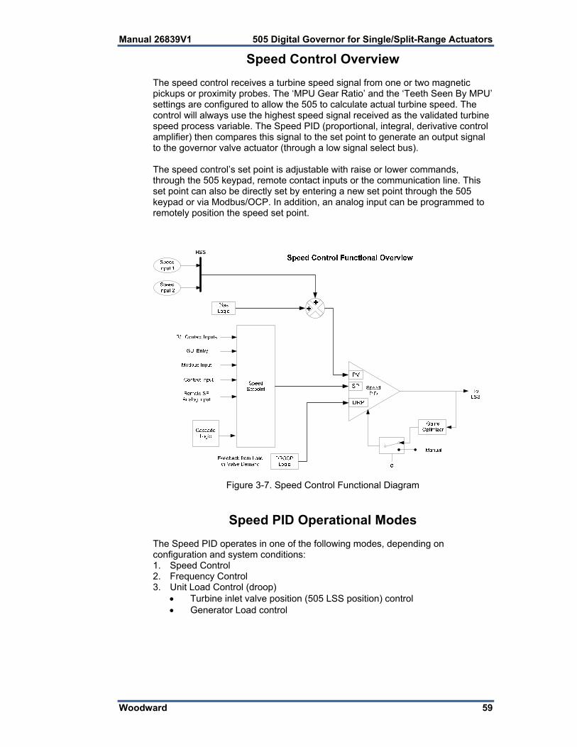
Manual 26839V1 505 Digital Governor for Single/Split-Range Actuators
Woodward 59
Speed Control Overview The speed control receives a turbine speed signal from one or two magnetic pickups or proximity probes. The ‘MPU Gear Ratio’ and the ‘Teeth Seen By MPU’ settings are configured to allow the 505 to calculate actual turbine speed. The control will always use the highest speed signal received as the validated turbine speed process variable. The Speed PID (proportional, integral, derivative control amplifier) then compares this signal to the set point to generate an output signal to the governor valve actuator (through a low signal select bus). The speed control’s set point is adjustable with raise or lower commands, through the 505 keypad, remote contact inputs or the communication line. This set point can also be directly set by entering a new set point through the 505 keypad or via Modbus/OCP. In addition, an analog input can be programmed to remotely position the speed set point.
Figure 3-7. Speed Control Functional Diagram
Speed PID Operational Modes The Speed PID operates in one of the following modes, depending on configuration and system conditions: 1. Speed Control 2. Frequency Control 3. Unit Load Control (droop)
Turbine inlet valve position (505 LSS position) control Generator Load control
505 Digital Governor for Single/Split-Range Actuators Manual 26839V1
60 Woodward
When not programmed for generator applications, the 505 Speed PID operates in a Speed control mode at all times. When programmed for generator applications, the state of the generator and utility tie breakers determine the operational mode of the Speed PID.
When the Generator breaker contact is open, the Speed PID operates in a Speed control mode.
When the generator breaker is closed and the utility tie breaker is open, the Frequency control mode is selected.
When both the generator and utility tie breakers are closed, a Unit Load control mode is selected.
Speed Control While in the Speed Control mode, the Speed PID will control a turbine at the same speed or frequency regardless of the load it is supplying (up to the unit’s load capability). With this configuration, no form of droop or second controlling parameter (bias logic) is used by the PID for stability or control. The following Speed PID mode descriptions are based on the 505 program’s default settings. For information on how to change the 505’s defaulted breaker logic, refer to Volume 2 of this manual. All pertinent speed control parameters are available through Modbus communications. See Chapter 6 for a list of all Modbus parameters. Frequency Control The following Frequency Control mode descriptions are based on the 505 program’s default settings. For information on how to change the 505’s defaulted breaker logic, refer to Volume 2 of this manual. The Speed PID operates in the Frequency control mode when the generator breaker is closed and the utility tie breaker is open. In the Frequency control mode, the unit will operate at the same speed or frequency regardless of the load it is supplying (up to the unit’s load capability). Refer to Figure 3-8. When breaker positions result in the Speed PID switching to Frequency control, the speed set point is instantly stepped to the last turbine speed (frequency) sensed before Frequency control was selected. This allows a bumpless transfer between modes. If the last speed sensed was not at the ‘Rated Speed Set Point’ (synchronous speed) setting, the speed set point will ramp to the ‘Rated Speed Set point’ setting at a defaulted rate of 1 rpm/s (tunable through the Service mode). In the Frequency control mode the speed set point can be varied with the Speed Set Point Raise/Lower commands, as desired, to allow manual synchronization across a tie breaker to an infinite bus. See the Synchronization section in this Chapter. For indication purposes, a relay can be programmed to energize when the unit is in Frequency control.

Manual 26839V1 505 Digital Governor for Single/Split-Range Actuators
Woodward 61
Unit Load Control The 505’s Speed PID can control two independent parameters when the generator breaker is closed; frequency when the generator is isolated, and unit load when the generator is paralleled with an infinite bus. When the generator breaker and utility tie breaker inputs are both closed, the Speed PID operates in a Unit Load mode. This method of allowing a PID to control a second parameter is referred to as Droop. Giving the Speed PID two parameters to control allows it to control unit load and act as a stabilizing effect for any change in bus frequency. With this configuration, when bus frequency decreases or increases, unit load increases and decreases respectively, based on the unit’s droop setting. The net effect is a more stable bus. See Figure 3-9 for a frequency and load relationship diagram.
Figure 3-8. Speed PID Control Modes

505 Digital Governor for Single/Split-Range Actuators Manual 26839V1
62 Woodward
The term “droop” was derived from an isolated unit’s speed reaction to an increase in load when another parameter (unit load) is fed back to a Speed PID’s summing junction. The Droop term, as used throughout this manual refers to a PID’s second controlling parameter. A second parameter representing unit load is fed back into the 505’s Speed PID to allow it to control two parameters; speed when operating in an isolated mode, and unit load when paralleled to an infinite bus. See Figure 3-9.
Figure 3-9. Frequency and Unit Load Relationship
Because the 505’s Speed PID and set point are used to control turbine speed and a second parameter, this second parameter (unit load) is normalized to allow all three terms (speed, set point, unit load) to be summed together within the PID summing junction. This normalization is based on a percentage of rated speed and creates a direct relationship between unit load and the Speed PID’s set point. Once unit load (0–100%) is represented as a percent of rated speed, the speed set point can be varied by this percent, above rated speed, to increase load from 0–100% when paralleled to the utility. Unit load is converted to a percentage of rated speed as shown in the following example calculation:
DROOP % x (gen load or valve position-%) x Rated Speed = Speed Set Point change in rpm Example: 5% x 100% x 3600 rpm = 180 rpm For this example when paralleled to a utility bus, the speed set point can be adjusted from 3600 rpm to 3780 rpm to vary unit load from 0 to 100%.
Manual 26839V1 505 Digital Governor for Single/Split-Range Actuators
Woodward 63
Droop feedback allows the Speed PID to control unit load (generator power or turbine valve position) once it is paralleled with a utility bus or other generating systems which do not have droop or load sharing capability. When a turbine generator set is paralleled with a utility bus, the utility determines the unit frequency/speed, thus the governor must control another parameter. The 505 uses turbine inlet valve position (LSS bus position) or generator load as a second parameter to control when paralleled to an infinite bus. The generator load or turbine inlet valve position droop percentage cannot be set greater that 10%, and is typically set to 5%. Optionally, the set droop percentage value can be changed from front panel, while turbine is running, or via a remote 4–20 mA signal (remote droop), to change the control’s response to grid frequency changes. In some extreme cases, where the utility grid frequency is unstable, and changes significantly (day/night), it is possible to change the unit’s: Frequency set point (50 Hz/60 Hz ±2.5 Hz) via front panel Frequency dead-band (±3 Hz). Used to reduce/prevent constant valve
corrections due to a constantly changing grid frequency. To configure the 505 for generator load control when paralleled to a infinite bus, check the ‘Use KW Droop’ option on the Operating Parameters page of the configuration menu. the 505 must also be configured to accept a KW Load signal either from an analog input from a Watt transducer sensing generator load, or from a Woodward Power Management product/device via a digital communication link (Woodward Links). To configure the 505 for turbine valve position control when paralleled to an infinite bus, uncheck the ‘Use KW Droop’ option . The generator load or turbine inlet valve position droop percentage cannot be set greater that 10%, and is typically set to 5%. If the 505 is programmed to control unit load using turbine inlet valve position droop (LSS bus position), the 505 calculates load based on the valve position at the time the generator breaker was closed. This valve position is considered to be zero load. In a typical application where turbine inlet and exhaust pressures are at rated levels when the generator breaker is closed, this type of calculation allows unit load to be accurately sensed, and controlled.
In an application where turbine inlet or exhaust pressures are NOT at rated levels when the generator breaker is closed, the considered zero load level will be incorrect when system pressures do reach rated levels.
If turbine inlet or exhaust pressures are not at rated when the breaker closes, it is recommended that the user do the following: Use the available tunable in Service mode to correct the valve position at zero load once the system is operating at rated steam pressure. To do this, adjust the Zero Load Value, (under the Service mode’s ‘BREAKER LOGIC’ header) and set this value to the correct valve position demand at Sync no load condition
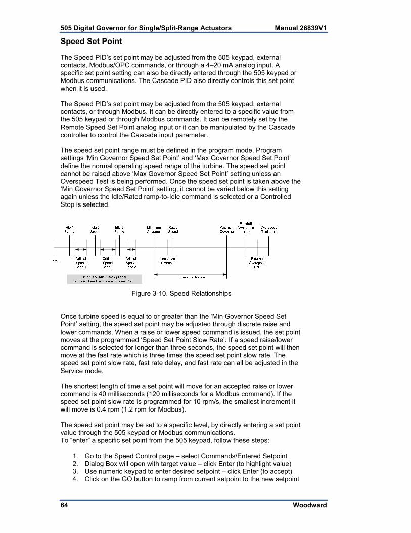
505 Digital Governor for Single/Split-Range Actuators Manual 26839V1
64 Woodward
Speed Set Point The Speed PID’s set point may be adjusted from the 505 keypad, external contacts, Modbus/OPC commands, or through a 4–20 mA analog input. A specific set point setting can also be directly entered through the 505 keypad or Modbus communications. The Cascade PID also directly controls this set point when it is used. The Speed PID’s set point may be adjusted from the 505 keypad, external contacts, or through Modbus. It can be directly entered to a specific value from the 505 keypad or through Modbus commands. It can be remotely set by the Remote Speed Set Point analog input or it can be manipulated by the Cascade controller to control the Cascade input parameter. The speed set point range must be defined in the program mode. Program settings ‘Min Governor Speed Set Point’ and ‘Max Governor Speed Set Point’ define the normal operating speed range of the turbine. The speed set point cannot be raised above ‘Max Governor Speed Set Point’ setting unless an Overspeed Test is being performed. Once the speed set point is taken above the ‘Min Governor Speed Set Point’ setting, it cannot be varied below this setting again unless the Idle/Rated ramp-to-Idle command is selected or a Controlled Stop is selected.
Figure 3-10. Speed Relationships
Once turbine speed is equal to or greater than the ‘Min Governor Speed Set Point’ setting, the speed set point may be adjusted through discrete raise and lower commands. When a raise or lower speed command is issued, the set point moves at the programmed ‘Speed Set Point Slow Rate’. If a speed raise/lower command is selected for longer than three seconds, the speed set point will then move at the fast rate which is three times the speed set point slow rate. The speed set point slow rate, fast rate delay, and fast rate can all be adjusted in the Service mode. The shortest length of time a set point will move for an accepted raise or lower command is 40 milliseconds (120 milliseconds for a Modbus command). If the speed set point slow rate is programmed for 10 rpm/s, the smallest increment it will move is 0.4 rpm (1.2 rpm for Modbus). The speed set point may be set to a specific level, by directly entering a set point value through the 505 keypad or Modbus communications. To “enter” a specific set point from the 505 keypad, follow these steps:
1. Go to the Speed Control page – select Commands/Entered Setpoint 2. Dialog Box will open with target value – click Enter (to highlight value) 3. Use numeric keypad to enter desired setpoint – click Enter (to accept) 4. Click on the GO button to ramp from current setpoint to the new setpoint

Manual 26839V1 505 Digital Governor for Single/Split-Range Actuators
Woodward 65
If a valid number was entered, the setting will be accepted as the new target setpoint. If an invalid number is “entered” the setting will not be accepted and the 505’s screen will momentarily display a value out-of-range message. This ‘Entered’ rate is tunable through the Service mode. Requirements for valid entries are the following:
Speed must be below the maximum governor setting Speed must be above the idle setting and not within any critical speed
avoidance band Once the speed set point is above the minimum governor setting, the set
point cannot be lowered below minimum governor If the unit is driving a generator and the unit is on-line, the speed set
point cannot be set below the minimum load setting (set in Service) The speed set point can also be directly entered from Modbus/OPC, however, the allowed range is between the minimum governor and the maximum governor speed settings. The allowed set point range is limited to between the minimum load and the maximum governor settings if the unit is driving a generator and the unit is on-line. When the 505 is configured for a generator application, a special speed set point rate (Sync Window Rate) is used to increase set point resolution around synchronous speed. This allows for tighter set point control to accommodate synchronizing manually or by an automatic synchronizer which interfaces to the 505 using discrete contacts. This Sync Window Rate is defaulted to two rpm/s and is only used when the generator breaker is open and the speed set point is within 10 rpm of rated speed. Both the synchronizing rate and the synchronizing window are tunable in the Service mode. When configured for generator applications a Minimum Load set point can be used by the 505 to reduce the chance of reverse powering a unit upon closing the generator breaker. With the utility tie breaker closed, when a generator breaker closed indication is received, the Speed set point is stepped to the Minimum Load setting. The Minimum Load setting is defaulted to 3% (changeable in the Service Mode). To disable the use of the Minimum Load Set Point, set the ‘Use Min Load’ setting (under the Service mode’s ‘BREAKER LOGIC’ header) to ‘Unchecked’ (Not Used). As a related feature, if ‘Use Min Load’ is selected and the parameter ‘Reverse Power on Controlled Stop’ in OPERATING PARAMETERS is NOT selected, then the 505 will use this Minimum Load setting as the lower speed setpoint limit whenever the breaker is closed When the 505 is configured for a mechanical drive application, a contact input can be configured to instantly step the speed setpoint to the minimum governor speed. This feature can only be used after the start up sequence has been completed. In addition to stepping the speed setpoint to the minimum governor speed, closing the contact input will also disable the Cascade and Auxiliary controls. See Chapter 6 for a list of all speed set point related Modbus parameters.

505 Digital Governor for Single/Split-Range Actuators Manual 26839V1
66 Woodward
Frequency Arm/Disarm The Frequency Arm/Disarm feature can be used only when load sharing is not being performed, to allow multiple units to operate on the same isolated bus. With this feature, one unit on a multiple unit isolated bus controls frequency and the other units operate in a unit-load mode. The unit controlling frequency is referred to as the “Swing Machine” because its load will swing (vary) depending on the load of the plant. Caution should be taken with this configuration to not overload or reverse power the “Swing Machine”. This feature, when programmed, allows an operator to Arm or Disarm a unit’s Frequency control mode while it is in operation. When Armed, a unit will switch to Frequency control if the plant-to-utility tie breaker opens. When Disarmed, a unit will stay in a unit-load control mode when the plant-to-utility tie breaker opens. To use this feature, the program’s ‘Use Freq Arm/Disarm’ setting box must be checked, the Sync/Load Sharing mode cannot be programmed, and a discrete command must programmed. The Frequency Arm/Disarm mode can be selected from a programmed contact input, Function key, or Modbus command. When the programmed contact input is closed the unit’s Frequency control mode is Armed. When the programmed contact input is open the unit’s Frequency control mode is Disarmed. Depending on a unit’s size, health, and running status, an operator may select which unit is designated as the plant Frequency control unit if or when the plant- to-utility tie breaker opens. Frequency control can be Armed at any time, but it will only go into control when the generator breaker is closed and the utility tie breaker is open.
Only one unit at a time should have its Frequency control mode armed. If multiple units try to control plant frequency at the same time, they may fight and cause system instability, with the potential of damage to the equipment due to overloading or reverse-powering a machine.
If the ‘Use Freq Arm/Disarm’ setting box is unchecked, Frequency control is always Armed and the unit will go into Frequency control when the utility tie contact is open. If the program’s ‘Use Freq Arm/Disarm’ setting box is checked, then Frequency control must first be armed before the unit will switch into Frequency control when the utility tie contact is open.
Tie Breaker Contact Status
Gen Breaker Contact Status
Frequency Arm Speed Control Mode Initial Speed Reference
Cascade or Auxiliary (if used)
closed open XXXX Speed, Off-Line Dynamics
XXXX not active
closed closed XXXX Unit Load Control, On-Line Dynamics
Droop Setpoint active
open open XXXX Speed, Off-Line Dynamics
XXXX not active
open closed Arm Frequency Control, Off-Line Dynamics
Current Speed then Rated
not active
open closed Disarm Droop, Off- Line dynamics
Droop Setpoint not active
Table 3-1. Frequency Arm/Disarm Generator Control Modes

Manual 26839V1 505 Digital Governor for Single/Split-Range Actuators
Woodward 67
Speed Control Dynamics The 505 has a variety of options for the setting of dynamics (PID gain settings). When a system needs variable response times, due to changing system conditions, these dynamic variables allow the Speed PID to be tuned for optimal response. There values are separated into 2 main operational conditions, Off-Line and On-Line. Off-Line and On-Line - When the 505 is configured for a generator application, the utility tie and generator breakers determine which set of dynamics is used by the Speed PID. The speed PID’s off-line dynamics are selected when either the utility tie or generator breakers are open. The Speed PID’s on-line dynamics are selected if both breakers are closed (see Table 3-2). When not configured for a generator application, the 505 uses the programmed ‘Min Governor Speed Set Point’ setting to determine which set of dynamic values are used by the Speed PID. The Speed PID’s off-line dynamics are selected when turbine speed is below the ‘Min Governor Speed Set Point’ setting. The Speed PID’s on-line dynamics are selected when turbine speed is above the ‘Min Governor Speed Set Point’ setting. (see Table 3-2). When not configured for a generator application, the 505 will transfer from off- line to on-line dynamics once minimum governor speed is reached. Optionally a contact input may be programmed to perform a “Select On-Line Dynamics” function. If this contact is programmed the utility tie and generator breaker positions (gen applications), and the minimum speed setting status (non- gen applications) do not effect dynamics selection. When the programmed contact input is open, off-line dynamics are selected and used by the Speed PID. When the programmed contact input is closed, on-line dynamics are selected and used by the Speed PID. A relay can be programmed to indicate that the On-Line Dynamics are selected and used by the Speed PID. ON-LINE DYNAMICS OFF-LINE DYNAMICS CONFIGURATION SELECTED SELECTED GEN SET BOTH BREAKERS CLOSED EITHER BREAKER OPEN NOT A GEN SET SPD > MIN GOV SETTING SPD < MIN GOV SETTING *CONTACT INPUT CLOSED OPEN
*The contact input option has priority, when programmed.
Table 3-2. On-Line/Off-Line Dynamics Selection Dynamic Gain Settings – Dynamic gain values for the speed PID are initially defined in the configure mode and tunable at any time. For Off-Line settings there is 1 set of values for the Proportional, Integral and Derivative terms. The On-Line settings can be a single set of values or a curve created by optimizing the dynamics at 2 or 3 different load points. The procedure for setting these values is as follows.
1. Start by manually setting the gains for both Off-Line and On-Line conditions, referring to the PID Dynamic Adjustments section in this manual for completing this process.
2. Use the automated PID Dynamic Optimizer routine that will automatically analyze the system response and calculate ideal gains for that particular running condition.

505 Digital Governor for Single/Split-Range Actuators Manual 26839V1
68 Woodward
3. Once the analysis is complete and the gains are calculated, the user can choose to keep these gains or return to the manual values. For ONLINE operation, this routine can be performed at low, medium and high load points to create an ideal gain curve for optimum dynamics at all load conditions.
Refer to the PID Dynamic Adjustments section in this manual for more information on the PID Dynamic Optimizer procedure. Remote Speed Set Point The Speed set point can be positioned remotely through an analog signal by programming the Remote Speed Set Point analog input function. This allows the Speed set point to be set remotely by a process control or distributed plant control system. The remote speed set point input directly affects the 505’s speed set point. The maximum rate at which the remote input signal can change the speed set point is programmable. When the remote set point is enabled, the speed set point will move at a much slower rate until the two settings are matched at which time the speed set point will be allowed to move at the maximum rate. The Remote Speed Set Point (RSS) range is determined by the programmed Analog input’s 4 mA and 20 mA settings. The Remote Speed Set Point range is tunable in the Service mode (under REMOTE SPEED SETTINGS), but cannot control outside of the min governor and max governor speed set point values. Since RSS is a secondary speed setting function, the Speed PID must be in-control of the 505’s LSS bus to allow the RSS to position the actuator. When configured as a generator application, the RSS will not take control unless both breakers are closed and the speed PID is in control. When not configured as a generator application, turbine speed must reach min governor before the RSS can take control. The Cascade and Auxiliary (if configured to be enabled/disabled) controls are automatically disabled if RSS is enabled. The Remote Speed Set Point may be enabled or disabled from the 505 keypad, external contact or Modbus. The last command given from any of these three sources dictates the enabled/disabled state. It does not matter whether the last command was given from the keypad or other devices. A contact input can be programmed to perform as an external “Remote Speed Set Point Enable” function. When this programmed contact is open the RSS is disabled, and when it is closed the RSS is enabled. The contact can be either open or closed when trip condition is cleared. If the contact is open it must be closed to enable the RSS. If the contact is closed it must be opened and re-closed to enable the RSS function. If the milliamp signal to the Remote Speed set point input is out of range (below 2 mA or above 22 mA) an alarm will occur and the Remote Speed set point will be inhibited until the input signal is corrected and the alarm is cleared.

Manual 26839V1 505 Digital Governor for Single/Split-Range Actuators
Woodward 69
Remote Speed Set Point Status Messages The Remote Speed Set Point may be in one of the following states (505 front panel screen messages): Disabled—The remote set point function is not enabled and will have no
effect on the speed set point. Enabled—The remote set point has been enabled. Active—The remote set point is in control of the Speed set point but the
speed PID is not in control of the actuator output. In Control—The remote set point is in control of the Speed set point and the
speed PID is in control of the actuator output. Inhibited—RSS cannot be enabled. The input signal has failed, a controlled
stop is selected, the unit is shut down, or RSS is not programmed. When enabled, the Remote Speed set point may not match the Speed set point. In this case, the Speed set point will ramp to the Remote Speed set point at the programmed ‘Speed Set Point Slow Rate’ setting (as defaulted in the Service mode). Once in control, the maximum rate that the Speed set point will ramp, for a RSS change, is at the programmed ‘Remote Speed Set Point Max Rate’ setting. If the ‘Remote Speed Set Point Max Rate’ were set at 10 rpm/s and the Remote Speed set point analog input instantly moved from 3600 rpm to 3700 rpm, the Speed set point will move to 3700 rpm at 10 rpm/s. Refer to Volume 2 of this manual for information on related Service mode tunables. All pertinent Remote Speed Set Point parameters are available through the Modbus links, refer to Chapter 6 for a complete listing of Modbus parameters. Synchronization Automatic generator synchronization can be performed through a Woodward EGCP-3, easYgen, or DSLC-2. The DSLC-2 product is the easiest to integrate with the 505 as it can be integrated via a digital communication connection by using the Woodward Links wizard. In some cases, the analog input signal interfaces described below are not required, but can be used as a redundant signal if desired. These products connect to a 505 analog input to bias the 505’s speed set point directly to vary generator speed, frequency and phase. Optionally these products can interface with the unit voltage regulator to match system voltage across a generator breaker. When the 505 is configured for a Generator application, a special speed set point rate (Sync Window Rate) is used to increase set point resolution around synchronous speed. This allows for tighter set point control to accommodate synchronizing manually or by an automatic synchronizer which interfaces to the 505 discretely. This Sync rate is defaulted to two rpm/s and is only adjustable through the 505’s Service mode. This rate is only used when the generator breaker is open and the actual speed is within +10 rpm of rated speed (also tunable through the Service mode).

505 Digital Governor for Single/Split-Range Actuators Manual 26839V1
70 Woodward
These products can be used as a synchronizer only or as a synchronizer and load control. When used as a synchronizer only, the 505 must be configured to accept the products analog Speed Bias signal and have this input enabled. A ‘Sync Enable’ contact input can be programmed to enable the 505’s synchronizing input when synchronization is desired. The Sync Enable command becomes disabled when the generator breaker closes, however, it may re-enabled again to allow the load management product to perform tie breaker synchronizations. To re-enable this input the ‘Sync Enable’ contact must be opened and re-closed. Typically a double pole single throw (DPST) switch is used on a site’s synchronizer control panel to select automatic synchronizing by enabling both the load management product sync mode and 505 analog input at the same time. Alternatively this signal can be sent to the 505, and the 505 can configure a relay output to send this Enable command to the synchronizer. To configure the 505 to utilize a load management product for generator synchronization only, program the ‘Synchronizing input’ function setting and program the ‘Sync Enable” function to a ‘CONTACT INPUT X’ setting. The ‘Synchronizing input’ function has a menu to allow this signal to come from the digital communication link, or from an Analog Input. If an AI is used, the range and gain settings are preset and are tunable only in the Service mode. Thus the 4 mA and 20 mA Program Mode settings for the Synchronizing input are irrelevant and are not used by the function’s operation. See Volume #2 of this manual. When the 505 is programmed to use a load management product for Synchronization, the Speed Control screen can also be used to access and enable the Synchronizing function and monitor all synchronization mode messages. The following synchronizing mode messages can be viewed: Disabled—The Synchronizing Input is disabled and will have no effect on
the Speed set point. Enabled—The Synchronizing Input has been enabled. In Control—The Synchronizing Input is biasing the Speed set point. Inhibited—The Synchronizing Input is inhibited and cannot be enabled. input
signal is failed, both the utility tie and generator breakers are closed, the turbine is shut down, a controlled shutdown is being per-formed, or synchronizing control is not programmed.
Synchronizing/Load Sharing The 505 is capable of using an analog input to accept a load sharing signal from Woodward’s EGCP-3, easYgen or DSLC-2. The DSLC-2 product is the easiest to integrate with the 505 as it can be integrated via a digital communication connection by using the Woodward Links wizard. With this connection, the analog input signal interfaces described below may not required, but can be used as a secondary backup signal if desired. This input in conjunction with these power management products allows the control to isochronously load share with any other system using the same product. The 505’s internal summing junction adds this signal with the speed/load PID’s reference. In addition to load sharing, this signal input to the 505 can be used to synchronize the unit to either the plant bus or to the utility.

Manual 26839V1 505 Digital Governor for Single/Split-Range Actuators
Woodward 71
Each of these power management products is able to provide VAR/Power Factor control, allowing all of the units to reactive load share as well as real power load share. These products sense unit load through generator PTs & CTs and system load through the network interconnects (a combination of all units on the same bus). When used as a synchronizer and load control, these products perform automatic synchronization and control unit load based on an internal base-load setting, a system average load setting, a process loop’s control setting, or a Master Synchronizer & Load Control’s (MSLC) demand setting. After synchronization, unit load can be controlled by the power management product through the Sync/Load Share input or by the 505’s internal speed/load set point. The Utility Tie Breaker Contact is used to select unit load control through the 505’s internal load set point. When the 505’s internal load control is selected (utility tie contact closed), the Speed PID set point is used to control unit load. Optionally the Cascade or Auxiliary control modes may be used to set unit load based on another system parameter. The EGCP-3 interfaces to the 505 via its Speed Bias signal. To configure the 505 to utilize a load management product for generator synchronizing and load sharing, program the ‘Sync/Load Share input’ function to one of the Analog Inputs setting and program the ‘Sync/Ld Share Enable” function to a ‘Contact Input #X’ setting. The ‘Sync/Ld Share input’ function has preset range and gain settings that are tunable only in the Service mode (see Volume 2). Thus the 4 mA and 20 mA Configuration Mode settings for the Synchronizing input are irrelevant and are not used by the function’s operation.
A combination of the Utility Tie Breaker contact, Generator Breaker contact, and Sync/Ld Share Enable contact define the state of the 505’s synchronizing and load sharing operating modes (See Table 3-3). The Utility Tie breaker contact input is used to enable and disable Load Sharing when the generator breaker is closed. If the Utility Tie contact is open, load sharing is enabled, and the 505’s internal Speed PID droop, Cascade, and Auxiliary modes are disabled (as defaulted in Service mode). If the Utility Tie contact is closed load sharing is disabled and the 505’s Speed PID droop, Cascade, and Auxiliary modes are enabled, if used. The Generator Breaker contact input is used in conjunction with the utility tie contact to activate load sharing. The ‘Sync/Ld Share Enable’ contact input option is used to enable the Sync/Load Share analog input before the generator breaker is closed. There is also a button on the speed Control screen that can be used to enable the 505’s Sync/Load Share analog input instead of an external contact. This discrete enable/disable function is ignored after the generator breaker is closed, and must be reselected after the generator breaker opens. Typically a double pole single throw (DPST) switch is used on a site’s synchronizer control panel to select automatic synchronizing by enabling both the power management product’s sync mode and 505 analog input at the same time.

505 Digital Governor for Single/Split-Range Actuators Manual 26839V1
72 Woodward
Figure 3-11. Load Sharing Logic
Tie Breaker Contact Status
Gen Breaker Contact Status
Sync/Ld Share Enable Contact
Speed Control Mode Initial Speed Reference
Cascade or Auxiliary (if used)
closed open open Speed, Off-Line Dynamics
XXXX not active
closed closed XXXX Unit Load Control, On-Line Dynamics
Droop Setpoint active
open open open Speed, Off-Line Dynamics
XXXX not active
open open closed Synchronizing Off-Line Dynamics
XXXX not active
open closed XXXX Load Sharing, Off- Line dynamics
Current Speed not active
Table 3-3. Load Sharing Logic
If using the display screen button to enable Sync/Load Share, then a 505 relay output, can be also be programmed to select the power management product’s synchronizing mode. To configure the 505 for this functionality, program the ‘Sync/Ld Share Enabled’ function to a ‘RELAY X ENERGIZES ON’ setting. When the 505 is programmed to use a load management product for Synchronization and Load Sharing, the Speed Control screen can also be used to access and enable these functions and monitor all synchronization mode messages.

Manual 26839V1 505 Digital Governor for Single/Split-Range Actuators
Woodward 73
The following synchronizing mode messages can be viewed: Disabled—The Sync/Load Share Input is disabled and will have no effect on
the Speed set point. Enabled—The Sync/Load Share Input has been enabled. In Control—The Sync/Load Share Input is biasing the Speed set point. Inhibited—The Sync/Load Share Input cannot be enabled; the input signal is
failed, the turbine is shut down, a controlled shutdown is being performed, or the sync/load share feature is not programmed.
All pertinent synchronizing and load sharing parameters are available through the Modbus links. See Chapter 6 for a complete listing of Modbus parameters.
Manual Demand The manual valve demand feature functions just like the valve limiter except that, instead of providing an input to the Low Signal Select to limit how high the valve demand can go, it disables all other controllers (including speed) to ensure that manual demand has full control of the valve demand output. The intent of this feature is to aid in the troubleshooting of plant stability or oscillation issues. It can be used to temporarily hold the valve in its current position. This feature can be selected using the Service Menu. In addition to holding the valve demand output, manual demand allows the valve demand to be adjusted manually, preferably at a very slow and safe rate. When selected, the valve ramp rate for this feature can be adjusted. This should be set to a value that is safe and stable for speed, load, or any process and pressures associated with the turbine that will be affected by moving this valve. Also, the timeout time can be adjusted. After this time the feature will disable if no raise/lower manual demand commands are received. Every time a raise or lower manual demand command is issued the timer will restart. Because of the risk associated with locking the valve in place there are many protections that disable this function, which will return the unit to Speed PID control, in addition to the normal disable command functionality and the timeout protection. All items that will disable this feature are as follows: Operator interface disable command Manual Demand not used (Service menu setting) Any Turbine Trip Startup not completed or Overspeed Test enabled Speed less than Minimum Governor Speed greater than Maximum Governor Both breakers not closed (generator applications only) Timeout due to inactivity
Manual Valve Demand
Use caution when adjusting manual demand as the 505 is no longer in control of any speed, load, or process. It is the responsibility of the operator to ensure safe operation of all processes related to valve movement. Use caution even while using this feature to hold the valve position as the 505 may not react to any system upsets until the conditions have become unsafe. Failure to do so may result in loss of control with possible personal injury, loss of life, or property damage.

505 Digital Governor for Single/Split-Range Actuators Manual 26839V1
74 Woodward
Load Rejection The Generator Load Rejection logic along with Woodward’s PID_OPTI block automatically react to large load drop events to reduce valve demand (energy) to minimize speed overshoot and prevent an overspeed trip when a load rejection occurs. For a generator application there are 2 types of events that result in large load transients. Event 1—At Generator Breaker Opening: This case is typically a ‘full load’ rejection of a unit running in Unit Load Control (Droop) against a Utility grid and all load of the steam turbine is lost. When the Generator Breaker is opened, and the speed exceeds more than 1% above rated speed, the control will immediately drive the HP valve demand to zero (0%). It will hold the valve at zero until the turbine speed decreases back to a level that is with 1% of the speed setpoint. This speed setpoint is identified as the Generator Breaker Open Setpoint and is defaulted to be 50 rpm below rated speed. Event 2—At Utility Breaker Opening (with GEN Breaker still closed): In this case, a unit that is normally running in Unit Load Control (Droop), against a utility, loses the Utility breaker, but the Generator breaker remains closed and the unit is switched to ‘Island mode’. In this case there is usually still some load on the turbine. When the Utility Breaker is opened, and the speed exceeds more than 1% above rated speed, the control will immediately drive the HP valve demand to zero (0%). It will hold the valve at zero until the turbine speed decreases back to a level that is with 1% of the speed setpoint. This speed setpoint is this case is rated speed.
Feed-Forward Input For 505 controllers configured for compressor applications, it is possible to experience a coupling effect between an anti-surge controller (external) and the 505’s internal Speed or Cascade PID controllers. If a plant condition exists where the anti-surge controller is required to open and control the anti-surge valve, compressor suction pressure will change. If the 505 Cascade controller is also controlling the compressor suction pressure, it will then respond to this pressure change, resulting in the two controllers temporarily affecting (fighting) each other. The 505 is capable of being configured to use an analog input (feed-forward signal) from an anti-surge controller. This input allows the 505 controller to decouple the response of its Speed and Cascade PID controls from that of the anti-surge controller, allowing for increased system stability in all conditions. Refer to this manual’s Speed Controller block diagram to better understand how this input is applied within the 505’s controller logic. This signal should represent the anti-surge controller’s anti-surge valve demand where 0% = 4 mA = Closed and 100% = 20 mA = Open. Delays in this signal should be kept to a minimum. This Feed-Forward function is only active when operating within the normal operating range (between Min Gov and Max Gov) and when it has been enabled. This function can be enabled/disabled through a contact input, programmable function key, or Modbus communications.

Manual 26839V1 505 Digital Governor for Single/Split-Range Actuators
Woodward 75
When enabled, if the feed forward analog input increases or decreases, the speed set point will be increased or decreased respectively. This is an offset added to or subtracted from the speed set point. After a feed-forward event, this speed offset will slowly ramp back to zero based on the delay time configured (typically 120 seconds). For example, if the max offset is 100 rpm with the max forward rate at 50%/s and the min offset is –75 rpm with the min forward rate at –25%/s and “Action Delay” is set to 120 seconds, then the following events describe the feed-forward action: 1. The speed set point is at Rated speed, X rpm. 2. The Feed-Forward Analog Input increases by 50% in one second. 3. The speed set point is instantly increased by 100 rpm. 4. The set point slowly decreases back to X rpm (at least 120 seconds). 5. The Feed-Forward Analog Input decreases by 25% in one second. 6. The speed set point is lowered by 75 rpm. 7. The set point slowly increases back to X rpm taking at least 120 seconds. The feed-forward loop can be configured for a temporary response, as described here, or as a direct action (continuous deviation based on the incoming signal). Emergency Loop In case of a compressor surge event, a large speed upset may occur, and recovery may be very difficult. If this event occurs, Emergency Feed-Forward action can be programmed to instantly bias the control’s speed reference using a larger offset than the regular feed-forward loop. When configured, the Emergency Feed-Forward bias action will increase the anti-surge controller’s effect for a short period, configured as the ‘Emergency Action Delay’, to assist the anti-surge controller with protecting the compressor. The Emergency Action takes effect when the Feed-Forward Analog Input increases or decreases faster than the configured ‘FW Rate to Activate’ (this should be larger than the ‘Min/Max Forward Rate’ used for the regular Feed Forward loop). The ‘Emergency Max Speed Offset’ will be added to the speed reference. This offset immediately begins ramping down and will reach zero after the configured ‘Emergency Action Delay’. At this point, only the normal feed forward action offset will be in effect since the emergency will typically have a much shorter duration. Direct Action When configured for direct action, the feed-forward loop will offset the speed set point proportional to its 4–20 mA calibration. This offset will not ramp back to zero; it remains active and offsets the speed reference based on the actual value of the Feed-Forward Analog Input. For example, if configured for a max offset of 150 rpm and a min offset of –50 rpm, then Direct Feed-Forward action offsets the set point by 0 rpm if the analog input is at 8 mA. The offset is 100 rpm if the analog input is at 16 mA, and the offset will not ramp down to 0; it remains at 100 rpm as long as the analog input is at 16 mA. The direct action cannot be used to decrease speed below Min governor and above Max Governor.

505 Digital Governor for Single/Split-Range Actuators Manual 26839V1
76 Woodward
Figure 3-12. Typical Anti-surge Valve and Speed Feed-Forward Logic Trend
Cascade Control The Cascade control can be configured to control any system process, related to or affected by turbine speed or load. Typically this controller is configured and used as a turbine inlet, or exhaust pressure controller. Cascade control is a PID controller that is cascaded with the Speed PID. The Cascade PID compares a 4–20 mA process signal with an internal set point to directly position the speed set point, thus changing turbine speed or load until the process signal and set point match. By Cascading two PIDs in this fashion, a bumpless transfer between the two controlling parameters can be performed. When enabled, the Cascade PID can move the speed set point at a variable rate up to the ‘Max Speed Set Point Rate’ setting (programmed under the CASCADE CONTROL header).

Manual 26839V1 505 Digital Governor for Single/Split-Range Actuators
Woodward 77
Figure 3-13. Cascade Functional Diagram Since Cascade is a secondary speed setting function, the Speed PID must be in control of the 505’s LSS bus in order for Cascade to take control. When the 505 is configured for a generator application, both the utility tie and generator breakers must be closed, before the Cascade PID can begin controlling a process. The selection of the Process Variable to use for this control is: Cascade Analog Input KW/Load Input Inlet Steam Pressure Exhaust Steam Pressure Cascade control may be enabled and disabled from the 505 keypad, a contact input, or Modbus communications. The last command given from any of these three sources dictates the Cascade PID’s control state. If a contact input is programmed to function as a Cascade Enable contact, when the contact is open Cascade control is disabled, and when it is closed Cascade control is enabled. This contact can either be open or closed when a trip condition is cleared. If the contact is open it must be closed to enable Cascade control. If the contact is closed it must be opened and re-closed to enable Cascade control. Cascade Control Status Messages Cascade is Disabled—Cascade control is not enabled and will have no
effect. Cascade is Enabled—Cascade has been enabled but is not active or in
control. Permissives have not been met (speed < min gov, generator or tie breaker open).
Casc Active/Not Spd Ctl—Cascade has been enabled but the Speed PID is not in control of the LSS bus (either aux or valve limiter is in control).
Cascade is In Control—Cascade is in control of the LSS bus.

505 Digital Governor for Single/Split-Range Actuators Manual 26839V1
78 Woodward
Casc Active w/Rmt Setpt—Cascade has been enabled and the Remote Cascade set point is in control of the set point but the Speed PID is not in control of the LSS bus.
Casc Control w/Rmt Setpt—Cascade is in control of the LSS bus (via the Speed PID) and the Remote Cascade Set Point is positioning the Cascade set point.
Cascade is Inhibited—Cascade cannot be enabled; the Cascade input signal has failed, a controlled stop is selected, the unit is shut down, or cascade control is not programmed.
Cascade control is automatically disabled on a shutdown condition, and must be re-enabled after a successful system start-up. Cascade control is disabled if Remote Speed Set Point is used and enabled. Should another parameter on the LSS bus take control of governor valve position from the Speed PID, Cascade control will stay active, and begin controlling again when the Speed PID is the lowest parameter on the LSS bus again. All pertinent cascade control parameters are available through the Modbus links, refer to Chapter 6 for a complete listing of Modbus parameters. Cascade Dynamics The Cascade PID control uses its own set of dynamic settings. These values are programmable and may be tuned at any time. Refer to the PID Dynamic Adjustments section in this manual. Cascade Set Point The Cascade set point can be adjusted from the 505 keypad, external contacts, Modbus commands, or through a 4–20 mA analog input. A specific setting can also be directly entered from the 505 keypad or through Modbus commands. The Cascade set point range must be defined in the program mode. Program settings ‘Min Cascade Set Point’ and ‘Max Cascade Set Point’ define the range of the Cascade set point and control.
Cascade set point raise/lower contact inputs act as speed set point raise/lower contacts when Cascade is not active or in control. This allows a single set of contacts (one SPDT switch) to control the Speed set point when the generator breaker is open, the load set point when paralleled to a utility, and the Cascade set point when enabled. Alternatively, a second set of contacts (speed raise and lower) could be used to independently control the speed and load set points.
When a raise or lower Cascade Set Point command is issued, the set point moves at the programmed ‘Casc Setpt Rate’ setting. If a Cascade raise or lower command is selected for longer than three seconds, the Cascade set point will move at the fast rate which is three times the cascade set point rate. The Cascade set point rate, fast rate delay, and fast rate can all be adjusted in the Service mode. The shortest length of time a set point will move for an accepted raise or lower command is 40 milliseconds (120 milliseconds for a Modbus command). If the Cascade set point slow rate is programmed for 10 psi/s, the smallest increment it will move is 0.4 psi (1.2 psi for Modbus).

Manual 26839V1 505 Digital Governor for Single/Split-Range Actuators
Woodward 79
A specific set point may also be directly entered from the 505 keypad or through Modbus communications. When this is performed, the set point will ramp at the ‘Casc Setpt Rate’ (as defaulted in Service mode). To “enter” a specific set point from the 505 keypad, press the CAS key to view the Cascade control screen, press the ENTER key, enter the set point level desired, then press the ENTER key again. If a valid number was entered, equal-to or between the min and max set point settings, the setting will be accepted and the Cascade set point will ramp to the “entered” set point level. If an invalid number is “entered”, the setting will not be accepted and the 505’s screen will momentarily display a value out-of-range message. When a valid set point value is entered, the set point will ramp at the Cascade Set Point Rate to the newly entered set point value. This ‘Entered’ rate is tunable through the Service mode. To “enter” a specific set point from the 505 Display use the following steps:
1. From the HOME page go to the Cascade Control page 2. Press the Commands button until ‘Entered Setpoint’ appears 3. Select ‘Entered Setpoint’ and a pop-up will appear 4. Press Enter from the Navigation cross and the pop-up value will highlight 5. Adjust the value with the Adjust keys or enter a value from the keypad 6. Press Enter again when desired value has been entered 7. The value in the pop-up will be accepted if it is valid, if it is out of range
then an error message will appear stating the entered value is invalid 8. Select the GO button to ramp the setpoint to this entered value
Refer to Volume 2 of this manual for information on which programmed settings are tunable through the 505’s Service mode. Service mode values can be tuned/adjusted while the 505 is shutdown or in the RUN mode. Cascade Set Point Tracking To allow a bumpless transfer from turbine Speed/load control to Cascade control, the Cascade PID can be programmed to track its controlling process input when disabled. When this tracking feature is programmed, the Cascade PID will be satisfied when enabled, and no turbine speed or load correction will be performed. After the Cascade control is enabled, its set point can moved, as required, to another setting. Cascade Set Point with No Tracking If the Cascade control is programmed not to use the set point tracking feature the set point will remain at its last setting (running or shutdown). When the 505 is powered-up the set point is reset to the ‘Setpt Initial Value’. With this configuration, when Cascade control is enabled, and its sensed process signal does not match set point, the Cascade control will ramp turbine speed/load up or down to match the two signals, at a controlled “not-matched” rate (defaulted to the ‘Speed Set Point Slow Rate’ setting, and tunable through the Service mode). If Cascade is the controlling parameter and one of the permissives is lost or Cascade is disabled, the speed set point will remain at its last setting until another parameter adjusts it.

505 Digital Governor for Single/Split-Range Actuators Manual 26839V1
80 Woodward
Cascade Droop When sharing control of a parameter with another external controller, the Cascade PID can also receive a programmable DROOP feedback signal for control loop stability. This feedback signal is a percentage of the Cascade PID’s output. By including this second parameter into the control loop, the Cascade PID becomes satisfied, and does not fight with the other external controller over the shared parameter. If Cascade droop is used, the Cascade input signal will not match the Cascade set point when in control. The difference will depend on the amount (%) of droop programmed and the output of the Cascade PID. The Droop value fed back to the Cascade PID is equal to the following defaulted settings:
PID OUTPUT % x ‘CASCADE DROOP %’ x ‘MAX CASC SET POINT’ x 0.0001 Where the ‘CASCADE DROOP %’ and ‘MAX CASC SET POINT’ values are set in the Program Mode and the ‘PID output %’ is determined by the Cascade demand. Example: 25% x 5% x 600 psi x 0.0001 = 7.5 psi
Refer to Volume 2 of this manual for information on related Service mode tunables. Invert Cascade Depending on the control action required, the Cascade input signal can be inverted. If a decrease in inlet governor valve position is required to increase the Cascade process signal, program the ‘INVERT CASCADE INPUT’ setting to ‘YES’. An example of this required control action would be when the Cascade PID is configured to control turbine inlet steam pressure. To increase turbine inlet steam pressure, the inlet control valve position must be decreased. Remote Cascade Set Point If desired, the Cascade set point can be positioned through an analog signal. Optionally, one of the 505’s six analog inputs can be programmed to position the Cascade PID set point. This allows the Cascade set point to be positioned remotely by a process control or distributed plant control system. The Remote Cascade Set Point (RCS) range is determined by the programmed Analog input’s 4 mA and 20 mA settings. The Remote Cascade Set Point range is tunable in the Service mode, but cannot be set outside of the min and max Cascade Set Point settings. The Remote Cascade Set Point input may be enabled from the 505 keypad, contact input, or Modbus communications. The last command given from any of these three sources dictates enable/disable. If the milliamp signal to the Remote Cascade set point input is out of range (below 2 mA or above 22 mA) an alarm will occur and the Remote Cascade set point will be inhibited until the input signal is corrected and the alarm is cleared. Depending on configuration and system conditions, the Remote Cascade Set Point may be in one of the following states (505 front panel screen messages):

Manual 26839V1 505 Digital Governor for Single/Split-Range Actuators
Woodward 81
Disabled—The Remote Set Point function is not enabled and will have no effect on the Cascade set point.
Enabled—The Remote Set Point has been enabled but cascade control is not active. The breakers are not closed, speed < min gov, or cascade has not taken control.
Active—The Remote Set Point has been enabled but Cascade is not in control. Cascade has been enabled and the Remote Cascade set point is in control of the set point but the Speed PID is not in control of the LSS bus.
In Control—Cascade is in control of the LSS bus (via the Speed PID) and the Remote Cascade Set Point is positioning the Cascade set point.
Inhibited—Remote Set Point cannot be enabled; input signal is failed, Cascade input signal is failed, a controlled stop is selected, the unit is shut down, or the remote cascade control is not programmed.
When enabled, the Remote Cascade set point may not match the Cascade set point. In this case, the Cascade set point will ramp to the Remote Cascade set point at the programmed ‘Casc Setpt Rate’ setting (as defaulted in the Service mode). Once in control, the fastest the Remote Cascade set point will adjust the Cascade set point is at the programmed ‘Rmt Cascade Max Rate’ setting. If the ‘Rmt Cascade Max Rate’ was set at 10 and the Remote Cascade set point analog input instantly moved from 0 units to 1000 units, the Remote Cascade set point will move to 1000 units at 10 units/s). Remote Cascade Enable Logic There are three different options for enabling Remote Cascade Set Point and Cascade control as follows: One Remote Enable contact input or function key command Both enable commands programmed; Remote Casc Enable and Cascade
Enable No enable commands programmed When only one Remote Enable command is programmed (either F-key or contact input), selecting ‘Enable’ will enable both Cascade control and Remote Cascade control. This configuration allows both functions to be enabled with one command if this is the normal operation mode. If ‘Disable’ is selected, both control modes are disabled. A contact input can be programmed to enable and disable the Remote Cascade Set Point (RCS) input/function. When this contact is open the RCS is disabled, and when it is closed the RCS is enabled. The contact can be either open or closed when a trip condition is cleared. If the contact is open it must be closed to enable the RCS input. If the contact is closed it must be opened and re-closed to enable the RCS input. When both Remote Cascade Enable and Cascade Control Enable commands are programmed, each function is enabled by its respective command selection. If Remote Cascade Enable is selected, only the Remote Cascade Set Point will be enabled. If Cascade Control Enable is selected, only Cascade control will be enabled. If Remote Cascade Disable is selected, only the Remote Cascade Set Point will be disabled. If Cascade Control Disable is selected, both Remote Cascade control and Cascade control will be disabled. However, if before the Cascade PID was ‘In-control’, a Cascade disabled command is given, only Cascade control will be disabled.

505 Digital Governor for Single/Split-Range Actuators Manual 26839V1
82 Woodward
If no external contact input or function keys are programmed for the ‘Enable’ commands, Cascade Control and Remote Cascade Control must be enabled from either the front panel keypad or from Modbus. Since the front panel and Modbus provide both Remote Cascade Enable and Cascade Control Enable commands, they will operate in the same manner as ‘both enables programmed’. Refer to Volume 2 of this manual for information on related Service mode tunables. All pertinent Remote Cascade control parameters are available through the Modbus links. See Chapter 6 for a complete listing of Modbus parameters.
Auxiliary Control The Auxiliary PID controller can be used to limit or control generator power, plant import/export power, turbine inlet pressure, turbine exhaust pressure, pump/compressor discharge pressure, or any other auxiliary parameters, directly related to turbine speed/load. The selection of the Process Variable to use for this control is:
Auxiliary Analog Input KW/Load Input Inlet Steam Pressure Exhaust Steam Pressure
Each of these inputs is a 4 to 20 mA current signal (the KW/Load could be from a ‘Woodward Links’ digital communication link). The PID control amplifier compares this input signal with the Auxiliary set point to produce a control output to the digital LSS (low-signal select) bus. The LSS bus sends the lowest signal to the actuator driver circuitry. The Auxiliary set point is adjustable with raise or lower commands through the 505 front keypad, through remote contact inputs or through Modbus. Also, the set point can be directly set by entering the new set point from the keypad or through Modbus communications. In addition, an analog input can be programmed to remotely position the Auxiliary set point.
Figure 3-14. Aux Control Overview

Manual 26839V1 505 Digital Governor for Single/Split-Range Actuators
Woodward 83
Auxiliary as a Limiter (not using Enable/Disable) When configured as a limiter, the Auxiliary control is low signal selected (LSS) with all of the other PIDs, allowing it to limit turbine speed/load based on any auxiliary parameter which is directly related. To configure the Auxiliary controller to function as a limiter, do NOT check the configuration parameter of ‘Use Aux as Controller’. When Auxiliary is configured to act as a limiter the Auxiliary PID will ‘limit’ the LSS bus when the input reaches the set point. The Aux set point initializes to the programmed ‘Setpoint Initial Value’ setting on a power-up-reset. This set point may be adjusted at any time and will remain at a setting (running or shutdown), provided a power-up-reset did not occur. Depending on configuration and system conditions, the Auxiliary Limiter may be in one of the following states (505 front panel screen messages): Auxiliary is Enabled—Auxiliary has been enabled but the generator and
utility tie breaker permissives have not been met (generator applications only).
Aux Active/Not Lmting—Auxiliary is configured as a limiter but is not limiting the LSS bus.
Aux Active w/Rmt Setpt—Auxiliary is not in control of the LSS bus and the remote Auxiliary input is in command of the set point.
Aux Control w/Rmt Setpt—Auxiliary is in limiting the LSS bus and the remote Auxiliary analog input is in command of the set point.
Auxiliary is Inhibited—Auxiliary cannot be enabled. The input signal has failed.
For generator applications, Auxiliary control limiting can be configured to be disabled when the generator and/or utility tie breakers are open. Program settings ‘Generator Breaker Open Aux Disable’ and ‘Tie Breaker Open Aux Disable’ may be configured to deactivate Auxiliary PID limiting, depending on system breaker positions. When both settings are programmed as unchecked (NO), the Auxiliary limiter will always stay ‘active’. If either setting is programmed as checked (YES), the Auxiliary limiter will be active only when the tie breaker or generator breaker respectively, is closed. If the unit is not configured for a generator application, the utility tie and generator breaker inputs do not affect Auxiliary limiter status, and the Limiter will be active at all times. Auxiliary as a Controller (using Enable/Disable) When configured as a controller, the Auxiliary PID may enabled and disabled on command. With this configuration, when Auxiliary control is enabled it instantly takes full control of the LSS bus, and the Speed PID is switched to a tracking mode. When Auxiliary control is disabled the Speed PID instantly takes full control of the LSS bus. To allow a bumpless transfer between modes, when the Auxiliary PID is enabled, the Speed PID tracks a few % above the Auxiliary PID’s LSS bus signal. When the Auxiliary PID is disabled, its set point tracks the Auxiliary PID’s process signal. To configure the Auxiliary controller to function as a controller, check the configuration box ‘Use Aux as Controller’ on the Auxiliary Control configuration page.
505 Digital Governor for Single/Split-Range Actuators Manual 26839V1
84 Woodward
The Speed PID will only track the Auxiliary PID LSS bus signal up to 100% speed/load. Thus if turbine speed/load reaches 100%, the Speed PID will protect the unit by limiting unit speed/load to less than or equal to 100%. Depending on the configuration and system conditions, the Auxiliary PID may be in one of the following states (505 front panel screen messages): Auxiliary is Disabled—Auxiliary is disabled and will have no effect on the
LSS bus. Auxiliary is Enabled—Auxiliary has been enabled but the generator and
utility tie breaker permissives have not been met (generator applications only).
Aux Active/Not in Ctrl—Auxiliary has been enabled, permissives met, but is not in control of the LSS bus.
Aux Active w/Rmt Setpt—Auxiliary has been enabled but is not in control of the LSS bus and the remote Auxiliary input is controlling the set point.
Auxiliary in Control—Auxiliary is in control of the LSS bus. Aux Control w/Rmt Setpt—Auxiliary is in control of the LSS bus and the
remote Auxiliary analog input is in control of the set point. Auxiliary is Inhibited—Auxiliary cannot be enabled; input signal is failed, 505
is in Frequency Control, controlled shutdown is selected, unit is shut down or Auxiliary control is not programmed.
For generator applications, Auxiliary control can be configured to be disabled when the generator and/or utility tie breakers are open. Program settings ‘Generator Breaker Open Aux Disable’ and ‘Tie Breaker Open Aux Disable’ may be configured to deactivate Auxiliary PID control, depending on system breaker positions. When both settings are programmed as unchecked (NO), the Auxiliary limiter will always stay ‘active’. If either setting is programmed as checked (YES), the Auxiliary limiter will be active only when the tie breaker or generator breaker respectively, is closed. If the unit is not configured for a generator application, the utility tie and generator breaker inputs do not affect Auxiliary control status, and the controller will be active at all times (capable of being enabled). Auxiliary control may be enabled from the 505 keypad (GUI), remote contacts, or Modbus/OPC communications. The last command given from any of these three sources dictates which state the Auxiliary control is in. If an external Auxiliary Enable contact is programmed, disable is selected when the contact is open and enable is selected when it is closed. The contact can be either open or closed when a trip condition is cleared. If the contact is open it must be closed to enable. If the contact is closed it must be opened and re-closed to enable. When configured as enable/disable controller, the Auxiliary control will automatically be disabled upon a shutdown condition. Auxiliary control will be disabled and inhibited when the 505 is in frequency control. If the Process Variable (PV) milliamp input signal is out of range (below 2 mA or above 22 mA) an alarm will occur and Auxiliary control will be inhibited until the input signal is corrected and the alarm is cleared. Optionally the unit can be programmed to issue a shutdown on a loss of the Auxiliary input process variable signal. Auxiliary Dynamics The Auxiliary PID control uses its own set of dynamic settings. These values are programmable and may be tuned at any time. Refer to the PID Dynamic Adjustments section in this manual.

Manual 26839V1 505 Digital Governor for Single/Split-Range Actuators
Woodward 85
Generator Load Limiter/Control On generator applications, the Auxiliary PID may be programmed to use the ‘KW/Unit Load Input’ signal instead of the Auxiliary input signal for limiting or control. This is the same input signal (KW/Unit Load input) used by the Speed PID for KW droop. This configuration allows the Auxiliary PID to limit or control generator power. Auxiliary Droop When sharing control of a parameter with another external controller, the Auxiliary control amplifier can also receive a programmable DROOP feedback signal for control loop stability. This feedback signal is a percentage of the LSS bus (control valve position). By including this second parameter into the control loop, the Auxiliary PID becomes satisfied, and does not fight with the other external controller over the shared parameter. The Droop % fed back to the Auxiliary PID is equal to the following defaulted settings:
LSS BUS OUTPUT % x ‘AUXILIARY DROOP %’ x ‘MAX AUX SET POINT’ x 0.0001 Example: 25% x 5% x 600 psi x 0.0001 = 7.5 psi Where the ‘AUX DROOP %’ is set in Program mode, ‘MAX AUX SET POINT’ value is determined by the upper range limit of the process variable selected and the ‘LSS bus output %’ is determined by the Auxiliary demand.
Invert Auxiliary Input Depending on the control action required, the Auxiliary PID’s input signal can be inverted. If a decrease in inlet control valve position is required to increase the Auxiliary process signal, program the ‘INVERT AUX INPUT’ setting to ‘YES’. An example of this control action would be when the Auxiliary PID is configured to control turbine inlet steam pressure. To increase turbine inlet steam pressure, inlet control valve position must be decreased. Auxiliary Set Point The Auxiliary set point can be adjusted from the 505 keypad, external contacts, Modbus/OPC commands, or through a 4–20 mA analog input. A specific setting can also be directly entered from the 505 keypad or through Modbus commands. The Auxiliary set point range must be defined in the program mode. Program settings ‘Minimum Auxiliary Setpoint’ and ‘Maximum Auxiliary Setpoint’’ define the range of the Auxiliary set point and control. When a raise or lower Auxiliary Set Point command is issued, the set point moves at the programmed ‘Auxiliary Setpoint Rate’ setting. If a Auxiliary raise or lower command is selected for longer than three seconds, the Auxiliary set point will move at three times at the fast rate which is three times the Auxiliary set point rate. The Auxiliary set point rate, fast rate delay, and fast rate can all be adjusted in the Service mode. The shortest length of time a set point will move for an accepted raise or lower command is 40 milliseconds (120 milliseconds for a Modbus command

505 Digital Governor for Single/Split-Range Actuators Manual 26839V1
86 Woodward
A specific set point may also be directly entered from the 505 keypad or through Modbus/OPC communications. When this is performed, the set point will ramp at the ‘Auxiliary Setpoint Rate’ (as defaulted in Service mode). To “enter” a specific set point from the 505 Display use the following steps:
1. From the HOME page go to the Auxiliary Control page 2. Press the Commands button until ‘Entered Setpoint’ appears 3. Select ‘Entered Setpoint’ and a pop-up will appear 4. Press Enter from the Navigation cross and the pop-up value will highlight 5. Adjust the value with the Adjust keys or enter a value from the keypad 6. Press Enter again when desired value has been entered 7. The value in the pop-up will be accepted, if it is invalid a message will
appear 8. Select the GO button to ramp the setpoint to this entered value
Refer to Volume 2 of this manual for further information on Service mode and on-line tunables. All pertinent auxiliary control parameters are available through the Modbus links. See Chapter 6 for a complete listing of Modbus parameters.
Remote Auxiliary Set Point Remote Aux Set Point The Auxiliary set point can be positioned through an analog signal. Optionally, one of the 505’s analog inputs can be programmed to position the Auxiliary PID set point. This allows the Auxiliary set point to be positioned remotely by a process control or distributed plant control system. The Remote Auxiliary Set Point (RAS) range is determined by the programmed Analog input’s 4 mA and 20 mA settings. The Remote Auxiliary Set Point range is tunable in the Service mode, but cannot be set outside of the min and max Auxiliary Set Point settings. When enabled, the Remote Auxiliary Set Point may not match the Auxiliary set point. In this case, the Auxiliary set point will ramp to the Remote Auxiliary Set Point at the programmed ‘Aux Set Point Rate’ setting (as defaulted in the Service mode). Once in control, the fastest the Remote Auxiliary Set Point will adjust the Auxiliary set point is at the programmed ‘Remote Aux Max Rate’ setting. If the ‘Remote Aux Max Rate’ were set at 10 and the Remote Auxiliary Set Point analog input instantly moved from 0 units to 1000 units, the Auxiliary set point will move to 1000 units at 10 units/s. If the milliamp signal to the Remote Auxiliary Set Point input is out of range (below 2 mA or above 22 mA) an alarm will occur and the Remote Auxiliary Set Point will be inhibited until the input signal is corrected and the alarm is cleared. Depending on configuration and system conditions, the Remote Auxiliary Set Point may be in one of the following states (505 display screen messages): Disabled—The Remote Set Point function is disabled and will have no effect
on the Aux set point. Enabled—The Remote Set Point has been enabled, but permissives are not
met. Active—The Remote Set Point has been enabled, permissives are met, but
Auxiliary PID is not in control of the LSS bus. In Control—The Remote Set Point is in control of the Auxiliary set point, and
the Auxiliary PID is in control of the LSS bus.
Manual 26839V1 505 Digital Governor for Single/Split-Range Actuators
Woodward 87
Inhibited—Remote Set Point cannot be enabled; Remote Set Point input signal is failed, Auxiliary control is Inhibited, or Remote Auxiliary Set Point is not programmed.
Remote Auxiliary Enable Logic The Remote Auxiliary Set Point input may be enabled from the 505 keypad, contact input, or Modbus/OPC communications. The last command given from any of these three sources dictates the state of the RAS input. A contact input can be programmed to enable and disable the Remote Auxiliary Set Point input/function. When this contact is open the RAS is disabled, and when it is closed the RAS is enabled. The contact can be either open or closed when a trip condition is cleared. If the contact is open it must be closed to enable the RAS input. If the contact is closed it must be opened and re-closed to enable the RAS input. When the Auxiliary PID is programmed to function as a limiter, the Remote Auxiliary Set Point may be enabled at any time when the 505 is in the RUN mode. When the Auxiliary PID is programmed as a Controller (enabled/disabled), there are three different options for enabling Remote Auxiliary Set Point and Auxiliary control as follows: Contact input configured for Remote Auxiliary Setpoint Enable From the 505 Display keypad Modbus/OPC command When only one Remote Enable command is programmed as a contact input, selecting ‘Enable’ will enable both Auxiliary control and Remote Auxiliary control. This configuration allows both functions to be enabled with one command if this is the normal operation mode. If ‘Disable’ is selected, both control modes are disabled. When both Remote Auxiliary Enable and Auxiliary Control Enable commands are programmed, each function is enabled by its respective command selection. If Remote Auxiliary Enable is selected, only the Remote Auxiliary Set Point will be enabled. If Auxiliary Control Enable is selected, only Auxiliary control will be enabled. If Remote Auxiliary Disable is selected, only the Remote Auxiliary Set Point will be disabled. If Auxiliary Control Disable is selected, both Remote Auxiliary control and Auxiliary control will be disabled. However, if before the Auxiliary PID was ‘In-control’ an Auxiliary Disable command is given, only Auxiliary control will be disabled. If no external contact inputs are programmed for the ‘Enable’ commands, Auxiliary Control and Remote Auxiliary Control must be enabled from either the front panel keypad or from Modbus. Since the front panel and Modbus provide both Remote Auxiliary Enable and Auxiliary Control Enable commands, they will operate in the same manner as ‘both enables programmed’. Refer to Volume 2 of this manual for information on related Service mode tunables. All pertinent Remote Auxiliary Set Point parameters are available through the Modbus links. See Chapter 6 for a complete listing of Modbus parameters.
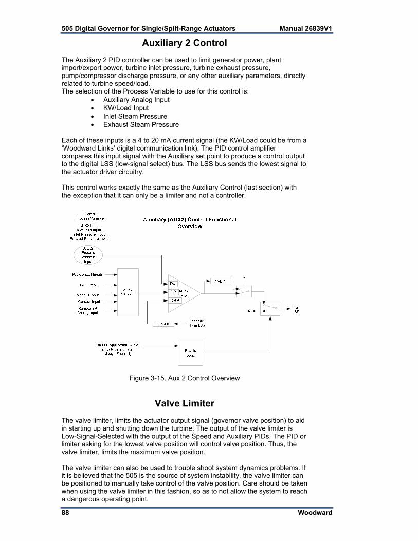
505 Digital Governor for Single/Split-Range Actuators Manual 26839V1
88 Woodward
Auxiliary 2 Control The Auxiliary 2 PID controller can be used to limit generator power, plant import/export power, turbine inlet pressure, turbine exhaust pressure, pump/compressor discharge pressure, or any other auxiliary parameters, directly related to turbine speed/load. The selection of the Process Variable to use for this control is:
Auxiliary Analog Input KW/Load Input Inlet Steam Pressure Exhaust Steam Pressure
Each of these inputs is a 4 to 20 mA current signal (the KW/Load could be from a ‘Woodward Links’ digital communication link). The PID control amplifier compares this input signal with the Auxiliary set point to produce a control output to the digital LSS (low-signal select) bus. The LSS bus sends the lowest signal to the actuator driver circuitry. This control works exactly the same as the Auxiliary Control (last section) with the exception that it can only be a limiter and not a controller.
Figure 3-15. Aux 2 Control Overview
Valve Limiter The valve limiter, limits the actuator output signal (governor valve position) to aid in starting up and shutting down the turbine. The output of the valve limiter is Low-Signal-Selected with the output of the Speed and Auxiliary PIDs. The PID or limiter asking for the lowest valve position will control valve position. Thus, the valve limiter, limits the maximum valve position. The valve limiter can also be used to trouble shoot system dynamics problems. If it is believed that the 505 is the source of system instability, the valve limiter can be positioned to manually take control of the valve position. Care should be taken when using the valve limiter in this fashion, so as to not allow the system to reach a dangerous operating point.

Manual 26839V1 505 Digital Governor for Single/Split-Range Actuators
Woodward 89
The valve limiter level is adjusted through the 505 keypad, contact input, or through Modbus communications. When raise or lower commands are received, the limiter ramps up or down, at the ‘VALVE LIMITER RATE’. The maximum the limiter can increase is 100%. The Valve Limiter ‘Rate’ and ‘Max Valve position’ settings can be adjusted in the Service mode. A specific set point may also be directly entered from the 505 keypad or through Modbus communications. When this is performed, the set point will ramp at the ‘Valve Limiter Rate’ (as defaulted in Service mode). To “enter” a specific set point from the 505 keypad, press the LMTR key to view the Valve Limiter screen, press the ENTER key, enter the set point level desired, then press the ENTER key again. If a valid number was entered, equal-to or between the min and max set point settings, the setting will be accepted and the Valve Limiter will ramp to the “entered” level. If an invalid number is “entered”, the setting will not be accepted and the 505’s screen will momentarily display a value out-of-range message. To “enter” a specific set point from the 505 Display use the following steps:
1. From the HOME page go to the Auxiliary Control page 2. Press the Commands button until ‘Entered Setpoint’ appears 3. Select ‘Entered Setpoint’ and a pop-up will appear 4. Press Enter from the Navigation cross and the pop-up value will highlight 5. Adjust the value with the Adjust keys or enter a value from the keypad 6. Press Enter again when desired value has been entered 7. The value in the pop-up will be accepted, if it is invalid a message will
appear 8. Select the GO button to ramp the setpoint to this entered value
When a valid set point value is entered, the set point will ramp at the ‘Valve Limiter Rate’ to the newly entered set point value. This ‘Entered’ rate is tunable through the Service mode. During start-up, if the control is set to use Automatic start-up, and if the valve limiter as been manually set for trouble shooting, it is possible to automatically ramp it back to 100%, by issuing a ‘Run’ command again. Refer to Volume 2 of this manual for further information on Service mode and on-line tunables. All pertinent valve limiter parameters are available through the Modbus links. See Chapter 6 for a complete listing of Modbus parameters.
Inlet Steam Pressure Compensation The inlet pressure compensation feature is used to adjust the control response based on variations in the inlet steam header pressure. Inlet pressure compensation is enabled in Configure Mode (under Operating Parameters). To use this feature, an analog input must be configured as inlet steam pressure. Once this is configured, the Pressure compensation curve will be available in the Service Menu screens. The compensation factor is determined by a user-defined curve. The X values of the curve points are inlet pressures in engineering units. The Y values of the curve points are a gain multiplier on the HP valve demand. By default, all Y values are initially set to 1.0. The X values should be set to the expected range of inlet pressure for normal operation, with at least one Point being the rated pressure and a gain of 1.0. Increase the gain (Y values) for pressures less than rated and decrease the gains for pressures greater than rated. This gain factor is applied to the valve demand prior to the valve linearization curve (if that option is used).

505 Digital Governor for Single/Split-Range Actuators Manual 26839V1
90 Woodward
Example: Curve for a Steam Turbine rated at 500 psi and operating range of +/-150 psi. X Y Point 1 350 1.2 Point 2 400 1.1 Point 3 500 1.0 Point 4 600 0.9 Point 5 650 0.8 All X values entered in the curve must be increasing. The curve block has been implemented such that it will limit the gain to the first and last points entered by the user. If the inlet steam pressure signal fails, then the curve is bypassed and the gain is forced to 1.0. The gain output of this curve should be left at 1.0 (all Y values at 1.0) until the control PID gains have been tuned at the rated inlet pressure. Once this is done, then the inlet pressure compensation curve points can be set for other inlet pressures.
Pressure compensation will affect the accuracy of the droop calculation when the 505 is configured for droop with valve position control.
Emergency Shutdown When an Emergency Shutdown condition occurs, the actuator output signal is stepped to zero milliamps, the Shutdown relay de-energizes, and the shutdown cause (first shutdown condition sensed) is displayed on the 505’s front panel. See Chapter 5 for a detailed list of the possible shutdown (Trip) conditions. Up to ten (10) Emergency Shutdown inputs (contact inputs) can be programmed to allow the 505 to indicate the cause of an emergency shutdown. By wiring trip conditions directly into the 505, instead of a trip string, the 505 can pass a trip signal directly to its output relay (to trip the T&T valve), and also indicate the first trip condition sensed. The 505’s total throughput time is 20 milliseconds (worse case). Each of these discrete input shutdown inputs will be time-stamped by the real-time clock with 1 ms resolution. All trip conditions are indicated through the 505’s front panel, and Modbus communications. The cause of the last trip is displayed by pressing the VIEW key under the TRIP LED. The last trip indication, is latched-in and can be viewed at any time after a trip and before the next trip condition is latched in. Once latched-in the last trip indication cannot be reset. This allows an operator to confirm what the trip condition was hours or days after the unit has been reset and restarted. In addition to the dedicated Shutdown relay, the other programmable relays may be configured as Shutdown condition or Trip relays. The Shutdown Condition relay may be programmed to indicate a shutdown condition on a remote panel or to a plant DCS. The Shutdown Indication relay is normally de-energized. This relay will energize upon any shutdown condition and stay energized until all trips have been cleared. The ‘Reset Clears Trip’ function has no effect on the programmable Shutdown Indication relay. When programmed as a Trip relay, the respective relay will function like the dedicated Shutdown relay (normally energized and de-energizes on a shutdown) to indicate the position of the dedicated Shutdown relay.

Manual 26839V1 505 Digital Governor for Single/Split-Range Actuators
Woodward 91
Controlled Shutdown The Controlled Shutdown function is used to stop the turbine in a controlled manner, as opposed to an Emergency Trip. When a STOP command (controlled shutdown) is issued, the following sequence is performed: 1. Cascade and Auxiliary(if not a limiter) PID controllers are disabled 2. The Speed Set Point is ramped to min load set point at normal rate (only for
generator application). 3. When at min load (only for generator application), the controller will wait until
the generator breaker opens (only if “Reverse Power on Controlled Stop?” = False). If a relay output is configured as “generator open pulse (2s)”, then this relay will temporarily energize for 2 seconds.
4. The Speed Set Point is ramped to its low idle level. 5. Once the speed set point has reached its low idle point, the HP valve limiter
is then ramped to zero percent at a controlled rate. At this point if the “Controlled Stop & Trip” setting is configured to “no” the control will then wait for a Start command to restart the turbine. However, if the “Controlled Stop & Trip” setting is configured to “yes” the control will then execute a turbine shutdown.
For redundant configurations, the “Control Stop & Trip” setting should be configured to “yes”. This will shut down the “Tracking” unit at the end of the controlled shutdown. If the “Control Stop & Trip” setting is configured as “no”, the “Tracking” unit will trip on an MPU failure as the Unit rolls down.
With the control in the run mode and the turbine turning, when the 505’s “STOP” key is pressed, the control will display a message prompting the operator to verify the command (“Initialize Normal Stop?”). At this point, if the “OK” command is issued, the control will perform the controlled shutdown sequence explained above. Issuing the “Cancel” command will cause no change in the 505’s operation and the Normal Stop confirmation pop-up box will disappear. This verification feature prevents an unwanted shutdown if the STOP key is accidentally pushed. A controlled shutdown can be initiated or aborted from the 505 front panel, a programmed contact input or either Modbus communication link. Verification is not required if a controlled shutdown command is initiated by a programmed contact input or Modbus communication link. The controlled shutdown sequence can be aborted at any time. During a controlled shutdown sequence, by pressing the STOP key, the 505 will display a “Abort Normal Stop?” message. Selecting “OK” from this screen will cause the shutdown sequence to be aborted. At this point the shutdown sequence can be re-initiated when desired, or the unit can be brought back to a fully operational state. If an external contact is programmed to issue a controlled shutdown command, closing the contact will initiate the controlled shutdown sequence. The shutdown sequence will go through the same steps described above, with the exception that verification of the shutdown sequence is not needed. Opening the programmed contact will stop the sequence. The contact can be either open or closed when a trip condition is cleared. If the contact is open it must be closed to issue the command. If the contact is closed it must be opened and re-closed to issue the command. The Modbus initiated Control Shutdown Sequence requires two commands, one to start the sequence and the other to stop it.

505 Digital Governor for Single/Split-Range Actuators Manual 26839V1
92 Woodward
The speed sensor failure trip, generator breaker open trip, and tie breaker open trip commands are overridden when a controlled shutdown is initiated.
This command can be disabled through the Service Mode, if desired (see Key Options). When disabled, the Controlled Stop feature is disabled from front panel, Modbus, and contact commands.
See Chapter 5 of this Volume for all 505 service panel messages.
Overspeed Test Function The 505’s Overspeed Test function allows an operator to increase turbine speed above its rated operating range to periodically test turbine electrical and/or mechanical overspeed protection logic and circuitry. This includes the 505’s internal overspeed trip logic and any external overspeed trip device’s settings and logic. An Overspeed Test will allow the control’s speed set point to be increased above the normal maximum governor limit. This test can be performed from the front panel of the control or with external contacts. This test is not permissible through the Modbus. An overspeed test is allowed only under the following conditions: The Speed PID must be in control The Auxiliary, Cascade, and Remote Speed Set Point PIDs/functions must
be disabled If configured for a generator application the Generator breaker must be
open. The Speed Set Point must be at the, “Max Governor Speed” setting. If the ‘OSPD’ key is pressed or an external Overspeed Test contact is closed (if programmed) and the above conditions are not met the control will display a “Overspeed Test/Not Permissible” message. At any time the Max Peak Speed reached can be seen on the Overspeed Test page – it can be reset if the user is logged in at Service Mode level or above. An overspeed test can be performed through an external contact, if the ‘Overspeed Test’ function is programmed to a ‘Contact Input # Function’ setting. When configured this contact performs the same function as the 505’s front panel OSPD key. There are two programmable relay options available to indicate overspeed status. One programmable relay option indicates an Overspeed Trip condition. The second relay option provides indication that an Overspeed Test is being performed. See Chapter 5 of this manual for a complete Overspeed Test Procedure. All pertinent overspeed test parameters are available through the Modbus links. See Chapter 6 for a complete listing of Modbus parameters.

Manual 26839V1 505 Digital Governor for Single/Split-Range Actuators
Woodward 93
Local/Remote Function The 505’s Local/Remote function allows an operator at the turbine skid or 505 to disable any remote command (from a remote Control Room) that may put the system in a unsafe condition. This function is typically used during a system start-up, overspeed test or shutdown to allow only one operator to manipulate the 505 control modes and settings. The Local/Remote function must first be programmed before a Local or Remote mode can be selected by an operator. This function can be programmed under the OPERATING PARAMETERS BLOCK. If this function is not programmed all contact inputs and Modbus commands (when Modbus is programmed) are active at all times. If the Local/Remote function is programmed, Local and Remote modes can be selected through a programmed contact input, or Modbus command. When Local mode is selected, the 505 is defaulted to be operable from its front panel only. This mode disables all contact inputs and Modbus commands, with exceptions noted below:
External trip Contact In (defaulted in program) External trip 2 Contact In (active at all times, if programmed) External trip 3 Contact In (active at all times, if programmed) External trip 4 Contact In (active at all times, if programmed) External trip 5 Contact In (active at all times, if programmed) External trip 6 Contact In (active at all times, if programmed) External trip 7 Contact In (active at all times, if programmed) External trip 8 Contact In (active at all times, if programmed) External trip 9 Contact In (active at all times, if programmed) External trip 10 Contact In (active at all times, if programmed) External alarm 1 Contact In (active at all times, if programmed) External alarm 2 Contact In (active at all times, if programmed) External alarm 3 Contact In (active at all times, if programmed) External alarm 4 Contact In (active at all times, if programmed) External alarm 5 Contact In (active at all times, if programmed) External alarm 6 Contact In (active at all times, if programmed) External alarm 7 Contact In (active at all times, if programmed) External alarm 8 Contact In (active at all times, if programmed) External alarm 9 Contact In (active at all times, if programmed) Override MPU Fault Contact In (active at all times, if programmed) Frequency Arm/Disarm (active at all times, if programmed) Generator breaker Contact In (active at all times, if programmed) Utility tie breaker Contact In (active at all times, if programmed) Start permissive Contact In (active at all times, if programmed Switched dynamics Contact In (active at all times, if programmed) Select In-Control Unit Contact In (active at all times, if programmed) Local/Remote Contact In (active at all times, if programmed) Modbus Commands (can be active in Local with Service
setting)
For users familiar with the previous 505 version with 2-line displays, this feature is slightly different. In this 505 model, Modbus commands are inhibited when in local mode unless the “Enable When Local” Service settings is selected. This is available for each Modbus link. Note that the trip command and “Local/Remote” command are no longer exceptions to this rule. All addresses for the link will be considered either Local or Remote commands.

505 Digital Governor for Single/Split-Range Actuators Manual 26839V1
94 Woodward
When the Remote mode is selected the 505 can be operated through its front panel, contact inputs, and/or all Modbus commands. When using a contact input to select between Local and Remote modes, a closed contact input selects the Remote mode and an open contact input selects the Local mode. Optionally a relay can be programmed to indicate when Local mode is selected (energizes when the Local mode is selected). There is also indication of the Local/Remote mode selection through Modbus (address = true when the Remote mode is selected and false = when the Local mode is selected). The 505 is defaulted to only allow control operation though its front panel when the Local mode is selected. If desired, this defaulted functionality can be changed through the 505’s Service mode. The 505 can be modified to also allow operation through contacts inputs, or Modbus port #1 or Modbus port #2 when the Local mode is selected. All pertinent local/remote control parameters are available through the Modbus links. See Chapter 6 for a complete listing of all Modbus parameters.
Relays The 505 has eight relay outputs available. The first of these relays is dedicated for a system shutdown command from the 505. The second relay is configurable, but is defaulted for an alarm indication. The other six relays can be programmed for a variety of indications, and system functions. For fail-safe operation, the dedicated Shutdown relay is energized during normal system operation, and will de-energize when a shutdown occurs. The dedicated Alarm relay is normally de-energized. This relay will energize upon an alarm condition and stay energized until the alarm condition is cleared. Optionally this relay can be configured, through the 505’s Service mode, to toggle on and off repeatedly when an alarm conditions has occurred. With this configuration if a reset command is given and the alarm condition still exists, the relay will stop toggling and stay energized. The relay will start toggling again, upon a new alarm condition. This option can be used to inform the operator when another alarm condition has occurred. Any of the configurable relays can be programmed to function as a level switch or mode indication. When programmed as a level switch the relay will change state when the selected parameter reaches the programmed level (energizes when value is higher the programmed level). Relay Functional Clarifications The Shutdown Condition relay may be programmed to indicate a shutdown condition on a remote panel or to a plant DCS. The Shutdown Indication relay is normally de-energized. This relay will energize upon any shutdown condition and stay energized until all trips have been cleared. The ‘RESET CLEARS TRIP’ function has no effect on the programmable Shutdown Indication relay.

Manual 26839V1 505 Digital Governor for Single/Split-Range Actuators
Woodward 95
When programmed as a Trip relay, the respective relay will function like the dedicated “Shutdown” relay (normally energized and de-energizes on a shutdown) to indicate the position of the dedicated Shutdown relay. This relay output can be programmed to indicate a 505 initiated trip by setting the ‘Ext trips in Trip Relay’ option to NO. Using this option, 505 trip annunciation will only occur if the 505 tripped the turbine and not annunciate when the other external devices shuts down the unit (external trips). The Alarm Condition relay may be programmed to indicate an alarm condition on a remote control panel or to a DCS. The Alarm Indication relay is normally de- energized. This relay will energize upon any alarm condition and stay energized until all alarms have been cleared. If the ‘BLINK ALARMS’ option is ‘YES’ the programmable Alarm Condition relay will toggle on and off repeatedly when an alarm condition has occurred. With this configuration if a reset command is given and the alarm condition still exists, the relay will stop toggling and stay energized. The 505 Control Status OK relay is normally energized, and will only de-energize if unit inlet power is lost, the 505’s CPU fails, or the 505 is in the program mode. The Overspeed Test Enable relay will energize when an Overspeed Test is performed. This relay functions like the 505 OSPD key’s LED (it repeatedly toggles on and off when turbine speed is above the turbine Overspeed trip setting). An Underspeed Switch function can be programmed to indicate a turbine underspeed or overpower condition. If the Underspeed option is configured, once turbine speed reaches a level above the minimum governor speed setting, then decreases 100 rpm below the minimum governor speed setting, the respective relay energizes (indicating an underspeed condition). The ‘Underspeed setting’ is adjustable through the Service mode, under the ‘Speed Values’ header. When the Sync Enabled function is programmed, the assigned relay energizes when a synchronize command is given. After the unit generator or utility tie breaker is closed this function becomes disabled and the relay de-energizes. The 505’s Synchronization function can be used to synchronize across a generator breaker or utility tie breaker. When the Sync or Load Share Active function is programmed, the assigned relay energizes when a synchronizing or Load Sharing is active. When both the generator and utility tie breaker inputs are closed (Load Sharing not selected) this function becomes disabled and the relay de-energizes. When the Modbus Command function is programmed, the assigned relay energizes when the respective Modbus command “Turn On Modbus Relay X” is issued, then de-energizes when the respective Modbus command “Turn Off Modbus Relay X” is issued. This feature allows a 505 relay to be driven directly from Modbus to control a system related function (synchronizing). In addition, the assigned relay can be momentarily energized using the Modbus command “Momentarily Energize Modbus Relay X” is issued (voltage raise/lower commands). Refer to Chapter 6 of this manual for more information on Modbus commands.

505 Digital Governor for Single/Split-Range Actuators Manual 26839V1
96 Woodward
Chapter 4. Configuration Procedures
Program Architecture The 505 is easy to configure, due in large part to the menu-driven software. When the control is powered up and after the CPU self test has been completed, the control displays the home screen and the CPU LED on the left side of the front panel should be green. The operating procedures are divided into two sections: the Configuration Mode, discussed in this chapter, and the Run Modes (Operation and Calibration) (refer to Chapter 5 for RUN Mode information). The Configure Mode is used to configure the 505 for the specific application and set all operating parameters. The Run Mode is the normal turbine operation mode and is used to view operating parameters and run the turbine. The configuration cannot be changed or altered while the turbine is running, however, it can be accessed and all programmed values monitored. This minimizes the possibility of introducing step disturbances into the system. To monitor or review the program while in the run mode, enter the Configuration menu from the first (leftmost) soft key on the Home screen.
Display Modes and User Levels The 505 Display operates in several modes and access user levels, each of which has a different purpose. The modes are: OPERATION, CALIBRATION, and CONFIGURATION. In order to enter and exit a particular mode, the user must be logged in with an appropriate user level. These user levels are: MONITOR, OPERATOR, SERVICE, and CONFIGURE. In addition to granting authority to enter and exit modes, user levels also determine what parameters the user is authorized to adjust. See Table 4-1, Mode Access by User Level.
Mode
Operation Calibration Configuration
User Level
Monitor
Operator X
Service X X
Configure X X X
Table 4-1. Mode Access by User Level Mode Descriptions The OPERATION mode is the only mode that can be used to run the turbine. This is the default mode. Exiting CALIBRATION or CONFIGURATION mode will return to OPERATION mode. User levels: Operator, Service, or Configure. The CALIBRATION mode is used to force signal outputs in order to calibrate signals and field devices. In this mode, the actuator, analog, and relay outputs can be manually controlled. To enter this mode the turbine speed must be shutdown with no speed detected. User levels: Service or Configure.

Manual 26839V1 505 Digital Governor for Single/Split-Range Actuators
Woodward 97
The CONFIGURE mode is used to set up the parameters for a specific application prior to operation of the unit. To enter this mode the turbine speed must be shutdown with no speed detected. When the unit enters CONFIGURE mode the control is placed in IOLOCK which will disable all Output I/O channels. If the control is not shutdown, navigating through the configuration pages will allow viewing of CONFIGURE, but will not permit any changes to be made.
User Level Descriptions The Monitor user level is view-only access. All commands from the front panel are inhibited. All values displayed on each screen are continuously updated. The Operator user level allows for control of the turbine. Front panel commands to start, change setpoints, enable/disable functions, and stop the turbine are accepted. The Service user level allows the same commands as the Operator user level plus tuning of Service menu parameters and issuing of additional commands.. The Configure user level allows the same commands and access as the Service user level plus tuning of Configuration menu parameters.
Configuring the 505 Before the 505 can be used to operate any turbine, it must be configured with a valid configuration. A handy 505 Configure Mode Worksheet is provided in Appendix A of this manual. This chapter contains additional information related to completing this worksheet and configuring the specific application. It is recommended that this worksheet be completed and used to document your specific configuration. Figure 4-1 illustrates the 505 screen displayed when power is first applied and the unit is not configured. This is the HOME screen. It includes tips on how to enter the Configure Mode from this point. A password is required to protect against both intentional and inadvertent configuration changes. The password can be changed if desired, refer to Volume 2 for information on changing passwords. This screen will become the main menu once the unit is configured. From this HOME screen, operational screens as well as the Service and Configure menus can be accessed.
Figure 4-1. Initial HOME Screen (unit not configured)

505 Digital Governor for Single/Split-Range Actuators Manual 26839V1
98 Woodward
Use the following procedure to begin configuring the 505: 1. Press the MODE key. 2. Press the LOGIN softkey to open the User Login popup. 3. Login to the ‘Configure’ user level. 4. Close the User Login popup screen. 5. Press the Configuration softkey to enter configuration mode. Verify that
the following Calibration and Configuration Mode Permissives are met: a. Unit Shutdown b. No Speed Detected c. “Configure” User Level or greater is logged in
6. Press MODE or HOME to return to the HOME screen. 7. Press the Configuration softkey to access the configuration menus. 8. Use the navigation cross to navigate up/down/left/right and use ENTER
to select a menu or item. The 505 configure mode may be accessed if the unit is in a Shutdown state, no speed is detected, and the correct user level is logged in (Configure or higher). For safety reasons the configuration may be monitored only and no changes will be accepted if the turbine is running. By pressing the MODE key, pressing the soft key for LOGIN, and logging in as the “Configure” user level by entering the password (wg1113). Select a field using the navigation cross arrows and then press ENTER to enter text. When finished, press ENTER again. All configuration values and saved service mode changes are stored in the nonvolatile memory (EEPROMs) of the 505 control. To ensure that values are saved, exit Configure mode or select ‘Save Settings’ from the MODE screen. If power is removed from the 505 all saved values will return once power is restored. No batteries or back up power is required.
The field-configured portion of the configuration settings will be zeroed out after factory repair. You must reconfigure these values before the unit is put back into service.
Using Configure Menus Once the Configure Mode has been entered with the password, the specific application information must be entered into the 505. To access the configure menu, select the ‘Configuration’ softkey from the HOME screen. The navigation arrow keys (red navigation cross keypad; up, down, left, and right) are used for navigation of the Configure menus. Press ENTER to go into a menu. Then use the navigation cross to move up or down (left/right, if needed) in the menu. In the Program Mode, the control will generate an error message shown on the Configuration menu home screen as well as the MODE screen if an invalid configuration exits. A configuration error will cause the control to remain tripped. It is possible to exit program mode with such an error but the control will be tripped until the Configuration mode is entered again and the Configuration error is corrected. See the Tutorial to learn how to adjust a value. The tutorial can be accessed from the HOME screen by pressing the Tutorial softkey before the unit is configured or from the Service menu any time.

Manual 26839V1 505 Digital Governor for Single/Split-Range Actuators
Woodward 99
To return to the previous screen, press the ESC key. While in a Configure menu, to return to the main Configure menu screen, press the HOME key. To return to the main Home screen, press the HOME key again. To exit the Configure mode, go to the MODE screen and select the ‘Exit Configuration’ soft key. This will save values, exit I/O Lock, and reboots the 505. Configure Menus To program the control, navigate through the menus and configure the control features for the desired application. The first four configure menus listed below, as well as drivers and other I/O, must be programmed for every installation. The remaining menus contain optional features which can be selected if desired. The configure menus and their basic functions are described below.
Figure 4-2. Configuration Menu – Configuration Mode (Edit) Turbine Start– to configure start mode, idle/rated, and auto start
sequence settings; Speed Set Point Values– to configure speed set points, overspeed trip set
point, remote speed setting control and critical speed avoidance bands;
Speed Control– to configure MPU or PROX PROBE information and speed control dynamics settings;
Operating Parameters– to configure the unit for generator application, redundant operation, feed-forward and to use the local/remote function;
Auxiliary Control– to configure auxiliary control information; Auxiliary 2 Control– to configure auxiliary 2 control information; Cascade Control– to configure pressure, temperature control
information; Isolated Control– to configure isolated PID control information; Communications– to configure Modbus communication options; Analog Inputs– to configure analog input options; Analog Outputs (Readouts)– to configure analog readout options;

505 Digital Governor for Single/Split-Range Actuators Manual 26839V1
100 Woodward
Drivers– to configure driver outputs, pressure compensation, and, if not using driver 2, to use driver 2 for a 4–20 mA readout;
Contact Inputs– to configure contact input options; Relays– to configure relay options; Woodward Links– to configure digital communication links to other
Woodward products. The configure menus are described in detail below and contain information detailing each question and/or 505 configuration option. Each question/option shows the default (dflt) value and the adjustable range of that parameter (shown in parentheses). In addition, any additional constraints on the configuration are shown in italics following the description. There is a program mode worksheet in Appendix A of this manual that should be completed/filled-in and used as a guide for your particular application. This worksheet can also be used for future reference to document your application program. Turbine Start Menu Start Mode: (One of the three start modes must be selected before the unit will run.) MANUAL START? dflt= NO (Yes/No) Select this to configure a manual start mode. When configured for a manual
start mode, the operator controls the turbine speed from zero up to the minimum control speed using an external trip-throttle valve. The Manual Start Sequence would be: Push RUN. The actuator(s) automatically move to max position. Lastly, the operator slowly opens the trip-throttle valve until the governor takes control.
AUTOMATIC START? dflt= NO (Yes/No) Select this to configure an automatic start mode. When configured for an
automatic start mode, the 505 controls the turbine speed from zero up to the minimum control speed. The Automatic Start Sequence would be: Operator opens the T&T valve, then push RUN. The valve limiter opens automatically until the governor takes control.
SEMIAUTOMATIC START? dflt= NO (Yes/No) Select this to configure a semiautomatic start mode. When configured, the
505 valve limiter must be manually opened by the operator, slowly, to open the control valve and bring the turbine speed from zero up to the minimum control speed. The Semi-automatic Start Sequence would be: Open the T&T valve, then push RUN. The valve limiter must then be raised by the operator until governor takes control.
RATE TO MIN (rpm/s) dflt= 10.0 (0.01, 2000) Enter the speed set point acceleration rate to minimum. This is the rate the
set point moves from zero to the lowest controlling speed on a start command (assuming the turbine is at zero speed). The minimum controlling speed will be either ‘idle’ if idle/rated is used or ‘low idle’ if the auto start sequence is used. If neither of these start-up features is used, the min speed will be the minimum governor speed set point.
VALVE LIMITER RATE (%/s) dflt= 5.0 (0.1, 25) Enter the Valve Limiter Rate, in percent per second. This is the rate at which
the valve limiter moves when RUN is selected or when the limiter setting is changed through open/close commands. When using a semiautomatic or automatic start, this setting should be very slow—typically less than 2 %/s. When using a manual start, this setting is less critical and can be left at the default of 5 %/s.

Manual 26839V1 505 Digital Governor for Single/Split-Range Actuators
Woodward 101
Start Sequence: (One of the three start modes must be selected) NO START SEQUENCE ? dflt= YES (Yes/No) Select this if this no start sequence is desired. If not, skip to ‘Use
Idle/Rated’. If no start sequence is selected, the control will ramp to a programmable Minimum Governor speed set point when a START command is issued.
USE IDLE/RATED ? dflt= NO (Yes/No) If this is selected, the control will ramp from a programmable Idle speed to a
programmable Rated speed set point when Rated is selected through keypad, Modbus or external switch. If not, skip to ‘Use Auto Start Sequence’.
USE AUTO START SEQUENCE ? dflt= NO (Yes/No) If this function is configured and RUN is selected, the 505 automatically
accelerates the speed set point to a programmable low idle speed and holds for a programmable time then ramps to a programmable high idle speed and holds for a programmable time then ramps to programmable rated speed set point. The start sequence can be actuated or halted through the keypad, Modbus or external switch. If this is not selected, then the program will step to the ‘Use Temperature for Hot/Cold’ question.
USE TEMPERATURE FOR HOT/COLD dflt= NO (Yes/No) If this function is selected, it allows the turbine Hot/Cold status for startup to
be determined by using temperature analog inputs. Step to ‘Use Temperature Input 2’. If not selected, step to the ‘Reset Timer Level (rpm)’ question.
Hot Reset Level (rpm) dflt= 3000 (0.0, 20000) Enter the Level setting for the Hot Reset Timer. This is the speed setting
which is used to determine that the turbine has reached its HOT level. Speed must be above this level for five seconds to trigger the Hot Reset Timer.
(Must be greater than or equal to the ‘Minimum Governor’ Setting) Hot Reset Timer (min) dflt= 0 (0.0, 200) Enter the reset LEVEL Setting. This is the time needed, when RST Timer
level is reached, to transfer the start-up parameters from fully COLD to fully HOT.
COLD START (> xx HRS) dflt= 10 (0.0, 200) Enter the time in hours allowed after a trip before the ‘cold start’ sequence
curves are to be used. If this much time has expired (or more) after a trip condition, then the control will use the cold start values. If less than this time has expired, the control will interpolate between the hot and cold start values to determine rates and hold times.
HOT START (< xx HRS) dflt= 1.0 (0.0, 200) Enter the maximum time allowed after a trip for the ‘hot start’ sequence
curves to be used. If less than this time has expired after a trip condition, then the control will use the hot start values.
(Must be less than or equal to the ‘Cold Start’ Hours) USE TEMPERATURE INPUT 2 dflt= NO (Yes/No) If this function is selected, it allows the turbine Hot/Cold status for startup to
be determined by using 2 temperature analog inputs. To use the temperature difference feature, Temperature Input 2 must be used. If not selected, only 1 temperature AI will be used.
HOT MINIMUM TEMPERATURE 1 dflt= 1400.0 (0.0, 1.0e+38) Set the minimum temperature for the turbine to be considered HOT based
on temperature analog input 1. Above this temperature, the turbine is considered HOT for this input. See the functional description in this manual for other conditions that may be required for the turbine to be considered HOT.

505 Digital Governor for Single/Split-Range Actuators Manual 26839V1
102 Woodward
HOT MINIMUM TEMPERATURE 2 dflt= 1400.0 (0.0, 1.0e+38) Set the minimum temperature for the turbine to be considered HOT based
on temperature analog input 2. Above this temperature, the turbine is considered HOT for this input. See the functional description in this manual for other conditions that may be required for the turbine to be considered HOT.
USE WARM CONDITION dflt= NO (Yes/No) If this function is selected, an additional warm condition is available between
cold and hot, which means that each ramp rate and idle will allow a warm rate and hold time to be configured. If not selected, only Hot/Cold conditions will be used.
WARM MINIMUM TEMPERATURE 1 dflt= 1200.0 (0.0, 1.0e+38) Set the minimum temperature for the turbine to be considered WARM based
on temperature analog input 1. Above this temperature, the turbine is considered WARM for this input. See the functional description in this manual for other conditions that may be required for the turbine to be considered WARM.
WARM MINIMUM TEMPERATURE 2 dflt= 1200.0 (0.0, 1.0e+38) Set the minimum temperature for the turbine to be considered WARM based
on temperature analog input 2. Above this temperature, the turbine is considered WARM for this input. See the functional description in this manual for other conditions that may be required for the turbine to be considered WARM.
USE TEMPERATURE DIFFERENCE dflt= NO (Yes/No) If this function is selected, it allows the turbine Hot/Cold status for startup to
be determined by the difference between temperature analog inputs 1 and 2. Two temperature inputs must be configured. If not selected, Hot/Warm/Cold conditions will be based on the value of each temperature analog input and not the difference between the two.
HOT TEMPERATURE DIFFERENCE dflt= 10.0 (0.0, 1.0e+38) Set the temperature difference between temperature analog inputs 1 and 2
for the turbine to be considered HOT. If the difference is less than this value, the turbine is considered HOT. See the functional description in this manual for other conditions that may be required for the turbine to be considered HOT.
WARM TEMPERATURE DIFFERENCE dflt= 10.0 (0.0, 1.0e+38) Set the temperature difference between temperature analog inputs 1 and 2
for the turbine to be considered WARM. If the difference is less than this value, the turbine is considered WARM. See the functional description in this manual for other conditions that may be required for the turbine to be considered WARM.
IDLE SETPOINT (rpm) dflt= 1000 (0.0, 20000) Enter the Idle Speed set point desired. This is the lowest speed control set
point when using the Idle/Rated function. RATED SETPOINT (rpm) dflt= 3600 (0.0, 20000) Enter the Rated Speed set point desired. This is the speed control set point
that the unit accelerates to when using the Idle/Rated function. (Must be greater than or equal to the ‘Minimum Governor Speed’ Setting) IDLE/RATED COLD RATE (rpm/s) dflt= 5.0 (0.01, 2000) Enter the Idle/Rated cold rate (rpm/second). This is the at which the speed
set point moves between Idle and Rated speed set points when using the Idle/Rated commands and a COLD start is determined by the Hot/Cold start timer or temperature analog inputs if configured/used.
IDLE/RATED WARM RATE (rpm/s) dflt= 5.0 (0.01, 2000) Enter the Idle/Rated warm rate (rpm/second). This is the at which the speed
set point moves between Idle and Rated speed set points when using the Idle/Rated commands and a WARM start is determined by the temperature analog inputs if configured/used. The warm condition is only available when using temperature analog inputs.

Manual 26839V1 505 Digital Governor for Single/Split-Range Actuators
Woodward 103
IDLE/RATED HOT RATE (rpm/s) dflt= 5.0 (0.01, 2000) Enter the Idle/Rated rate (rpm/second). This is the at which the speed set
point moves between Idle and Rated speed set points when using the Idle/Rated commands and a HOT start is determined by the Hot/Cold start timer or temperature analog inputs if configured/used..
LOW IDLE SETPT (rpm) dflt= 1000 (0.0, 20000) Enter the Low Idle Speed Setting. This is the first hold speed when using the
automatic start sequence. The speed set point will remain at this setting until the low idle delay/hold time has expired.
LOW IDLE DELAY TIME—COLD (MINUTES) dflt= 1.0 (0.0, 500) Enter the cold start hold time desired at low idle. This is the programmable
time, in minutes, that the turbine will wait/hold at the low idle speed when a cold start is determined.
LOW IDLE DELAY TIME—WARM (MINUTES) dflt= 1.0 (0.0, 500) Enter the warm start hold time desired at low idle. This is the programmable
time, in minutes, that the turbine will wait/hold at the low idle speed when a warm start is determined. The warm condition is only available when using temperature analog inputs.
LOW IDLE DELAY TIME- HOT (MINUTES) dflt= 1.0 (0.0, 500) Enter the hot start hold time at low idle. This is the programmable time, in
minutes/seconds, that the turbine will wait/hold at the low idle speed when a hot start is determined. If the turbine has been shutdown for longer than the Hot time but shorter than the Cold time, the control will interpolate between the Hot and Cold delays to determine the low idle hold time.
Use IDLE 2? dflt= False When TRUE, the speed reference will ramp to Idle 2 level when timer is
passed. When FALSE is selected, the speed reference will go to rated speed. RATE TO IDLE 2—COLD (rpm/s) dflt= 5.0 (0.01, 500) Enter the cold start rate to Idle 2. This is the programmable rate, in rpm per
second, that the speed set point will accelerate at when moving to high idle when a cold start is determined.
RATE TO IDLE 2—WARM (rpm/s) dflt= 5.0 (0.01, 500) Enter the warm start rate to Idle 2. This is the programmable rate, in rpm per
second, that the speed set point will accelerate at when moving to high idle when a warm start is determined. The warm condition is only available when using temperature analog inputs.
RATE TO IDLE 2—HOT (rpm/s) dflt= 5.0 (0.01, 500) Enter the hot start rate to Idle 2. This is the programmable rate, in rpm per
second, that the speed set point will accelerate at when moving to Idle 2 when a hot start is determined. If the turbine has been shutdown for longer than the Hot time but shorter than the Cold time, the control will interpolate between the Hot and Cold rates to determine the acceleration rate to the Idle 2 set point.
IDLE 2 SETPT (rpm) dflt= 1100 (0.0, 20000) Enter the Idle 2 Speed Setting. This is the second hold speed when using
the automatic start sequence. The speed set point will remain at this setting until the Idle 2 Delay/hold time has expired.
(Must be greater than the ‘Low Idle’ Setting) IDLE 2 DELAY TIME—COLD (MINUTES) dflt= 1.0 (0.0, 500) Enter the cold start hold time desired at Idle 2. This is the programmable
time, in minutes, that the turbine will wait/hold at the Idle 2 speed when a cold start is determined.
IDLE 2 DELAY TIME—WARM (MINUTES) dflt= 1.0 (0.0, 500) Enter the cold start hold time desired at Idle 2. This is the programmable
time, in minutes, that the turbine will wait/hold at the Idle 2 speed when a warm start is determined. The warm condition is only available when using temperature analog inputs.

505 Digital Governor for Single/Split-Range Actuators Manual 26839V1
104 Woodward
IDLE 2 DELAY TIME—HOT (MINUTES) dflt= 1.0 (0.0, 500) Enter the hot start hold time desired at Idle 2. This is the programmable
time, in minutes, that the turbine will wait/hold at the Idle 2 speed when a hot start is determined. If the turbine has been shutdown for longer than the Hot time but shorter than the Cold time, the control will interpolate between the Hot and Cold delays to determine the hi idle hold time.
Use IDLE 3? dflt= False When TRUE, the speed reference will ramp to Idle 3 level when timer is
passed. When FALSE is selected, the speed reference will go to RATED speed. RATE TO IDLE 3—COLD (rpm/s) dflt= 5.0 (0.01, 500) Enter the cold start rate to Idle 3. This is the programmable rate, in rpm per
second, that the speed set point will accelerate at when moving to high idle when a cold start is determined.
RATE TO IDLE 3—WARM (rpm/s) dflt= 5.0 (0.01, 500) Enter the warm start rate to Idle 3. This is the programmable rate, in rpm per
second, that the speed set point will accelerate at when moving to high idle when a warm start is determined. The warm condition is only available when using temperature analog inputs.
RATE TO IDLE 3—HOT (rpm/s) dflt= 5.0 (0.01, 500) Enter the hot start rate to Idle 3. This is the programmable rate, in rpm per
second, that the speed set point will accelerate at when moving to Idle 3 when a hot start is determined. If the turbine has been shutdown for longer than the Hot time but shorter than the Cold time, the control will interpolate between the Hot and Cold rates to determine the acceleration rate to the Idle 3 set point.
IDLE 3 SETPT (rpm) dflt= 1200 (0.0, 20000) Enter the Idle 3 Speed Setting. This is the third hold speed when using the
automatic start sequence. The speed set point will remain at this setting until the Idle 3 Delay/hold time has expired.
(Must be greater than the ‘ Idle 2’ Setting) IDLE 3 DELAY TIME—COLD (MINUTES) dflt= 1.0 (0.0, 500) Enter the cold start hold time desired at Idle 3. This is the programmable
time, in minutes, that the turbine will wait/hold at the Idle 3 speed when a cold start is determined.
IDLE 3 DELAY TIME—WARM (MINUTES) dflt= 1.0 (0.0, 500) Enter the warm start hold time desired at Idle 3. This is the programmable
time, in minutes, that the turbine will wait/hold at the Idle 3 speed when a warm start is determined. The warm condition is only available when using temperature analog inputs.
IDLE 3 DELAY TIME—HOT (MINUTES) dflt= 1.0 (0.0, 500) Enter the hot start hold time desired at Idle 3. This is the programmable
time, in minutes, that the turbine will wait/hold at the Idle 3 speed when a hot start is determined. If the turbine has been shutdown for longer than the Hot time but shorter than the Cold time, the control will interpolate between the Hot and Cold delays to determine the Idle 3 hold time.
USE TEMPERATURE FOR IDLES dflt= NO (Yes/No) If this function is selected, it allows the temperature analog inputs to be used
to determine when the automatic start sequence can proceed from an idle setpoint. If not selected, only idle timers and halt/continue commands will be used.
USE TEMPERATURE INPUT 2 dflt= NO (Yes/No) If this function is selected, it allows 2 temperature analog inputs to be used
to determine when the automatic start sequence can proceed from an idle setpoint. To use the temperature difference feature, Temperature Input 2 must be used. If not selected, only 1 temperature AI will be used.

Manual 26839V1 505 Digital Governor for Single/Split-Range Actuators
Woodward 105
USE TEMPERATURE DIFFERENCE dflt= NO (Yes/No) If this function is selected, it allows the difference between temperature
analog inputs 1 and 2 to be used to determine when the automatic start sequence can proceed from an idle setpoint. Two temperature inputs must be configured. If not selected, idle hold conditions will be based on the value of each temperature analog input and not the difference between the two.
TEMPERATURE 1 SETPOINT FOR IDLE 1 dflt= 1500.0 (0.0, 1.0e+38) Set the temperature that must be reached for the automatic start sequence
to continue through the Idle 1 speed setpoint based on temperature analog input 1. Above this temperature, the Idle 1 condition will be satisfied for this temperature input. See the functional description in this manual for other conditions that may be required for the automatic start sequence to continue from Idle 1.
TEMPERATURE 2 SETPOINT FOR IDLE 1 dflt= 1500.0 (0.0, 1.0e+38) Set the temperature that must be reached for the automatic start sequence
to continue through the Idle 1 speed setpoint based on temperature analog input 2. Above this temperature, the Idle 1 condition will be satisfied for this temperature input. See the functional description in this manual for other conditions that may be required for the automatic start sequence to continue from Idle 1.
MAX TEMPERATURE DIFFERENCE FOR IDLE 1 dflt= 1500.0 (0.0, 1.0e+38) Set the temperature difference that must be achieved for the automatic start
sequence to continue through the Idle 1 speed setpoint based on the difference between temperature analog inputs 1 and 2. If the difference between temperature input 1 and 2 is less than this value, the Idle 1 condition will be satisfied. See the functional description in this manual for other conditions that may be required for the automatic start sequence to continue from Idle 1.
TEMPERATURE 1 SETPOINT FOR IDLE 2 dflt= 1500.0 (0.0, 1.0e+38) Set the temperature that must be reached for the automatic start sequence
to continue through the Idle 2 speed setpoint based on temperature analog input 1. Above this temperature, the Idle 2 condition will be satisfied for this temperature input. See the functional description in this manual for other conditions that may be required for the automatic start sequence to continue through Idle 2.
TEMPERATURE 2 SETPOINT FOR IDLE 2 dflt= 1500.0 (0.0, 1.0e+38) Set the temperature that must be reached for the automatic start sequence
to continue through the Idle 2 speed setpoint based on temperature analog input 2. Above this temperature, the Idle 2 condition will be satisfied for this temperature input. See the functional description in this manual for other conditions that may be required for the automatic start sequence to continue through Idle 2.
MAX TEMPERATURE DIFFERENCE FOR IDLE 2 dflt= 10.0 (0.0, 1.0e+38) Set the temperature difference that must be achieved for the automatic start
sequence to continue through the Idle 2 speed setpoint based on the difference between temperature analog inputs 1 and 2. If the difference between temperature input 1 and 2 is less than this value, the Idle 2 condition will be satisfied. See the functional description in this manual for other conditions that may be required for the automatic start sequence to continue through Idle 2.
TEMPERATURE 1 SETPOINT FOR IDLE 3 dflt= 1500.0 (0.0, 1.0e+38) Set the temperature that must be reached for the automatic start sequence
to continue through the Idle 3 speed setpoint based on temperature analog input 1. Above this temperature, the Idle 3 condition will be satisfied for this temperature input. See the functional description in this manual for other conditions that may be required for the automatic start sequence to continue through Idle 3.

505 Digital Governor for Single/Split-Range Actuators Manual 26839V1
106 Woodward
TEMPERATURE 2 SETPOINT FOR IDLE 3 dflt= 1500.0 (0.0, 1.0e+38) Set the temperature that must be reached for the automatic start sequence
to continue through the Idle 3 speed setpoint based on temperature analog input 2. Above this temperature, the Idle 3 condition will be satisfied for this temperature input. See the functional description in this manual for other conditions that may be required for the automatic start sequence to continue through Idle 3.
MAX TEMPERATURE DIFFERENCE FOR IDLE 3 dflt= 10.0 (0.0, 1.0e+38) Set the temperature difference that must be achieved for the automatic start
sequence to continue through the Idle 3 speed setpoint based on the difference between temperature analog inputs 1 and 2. If the difference between temperature input 1 and 2 is less than this value, the Idle 3 condition will be satisfied. See the functional description in this manual for other conditions that may be required for the automatic start sequence to continue through Idle 3.
RATE TO RATED SETPT—COLD (rpm/s) dflt= 5.0 (0.01, 500) Enter the cold start rate to the rated speed set point. This is the
programmable rate, in rpm per second, that the speed set point will accelerate at when moving to rated when a cold start is determined.
RATE TO RATED SETPT—WARM (rpm/s) dflt= 5.0 (0.01, 500) Enter the warm start rate to the rated speed set point. This is the
programmable rate, in rpm per second, that the speed set point will accelerate at when moving to rated when a warm start is determined. The warm condition is only available when using temperature analog inputs.
RATE TO RATED SETPT—HOT (rpm/s) dflt= 5.0 (0.01, 500) Enter the hot start rate to the rated speed set point. This is the
programmable rate, in rpm per second, that the speed set point will accelerate at when moving to rated when a hot start is determined. If the turbine has been shutdown for longer than the Hot time but shorter than the Cold time, the control will interpolate between the Hot and Cold rates to determine the acceleration rate to the rated set point.
(Must be greater than or equal to the ‘Rate to Rated—Cold’ Setting) RATED SETPOINT (rpm) dflt= 3000 (0.0, 20000) Enter the Rated Speed Setting. This is the final speed setting when using
the automatic start sequence. Once this speed set point is reached, the start sequence is complete.
(Must be greater than or equal to the ‘Minimum Governor’ Setting) AUTO HALT AT IDLE SETPOINTS? dflt= NO (Yes/No) Select YES to automatically halt the auto start sequence at the idle set
points. This feature would result in the unit automatically stopping/halting at the low idle set point and at the high idle set point. Also, if the unit is started and the speed is above the low idle set point, the sequence will be halted. Select NO to allow the control to perform its automatic start sequence routine without interruption.
Speed Set Point Values Menu (The maximum speed input frequency is 35000 hertz.) OVERSPEED TEST LIMIT (rpm) dflt= 1100 (0.0, 20000) Set the overspeed test limit (in rpm). This is the maximum speed set point
the control will increase to when overspeed testing the unit. The set point can only be raised to this level when the overspeed test function is being performed.
OVERSPEED TRIP LEVEL (rpm) dflt= 1000 (0.0, 20000) Set the 505’s overspeed trip level (in rpm). This is the governor overspeed
trip set point only and is not to be used as ultimate overspeed protection. (Must be less than the ‘Overspeed Test Limit’ Setting)

Manual 26839V1 505 Digital Governor for Single/Split-Range Actuators
Woodward 107
MAX GOVERNOR SPEED SET POINT (rpm) dflt= 1.0 (0.0, 20000) Set the maximum governor control speed. This is the normal governor
operation upper limit. For turbine/generator applications, this value must be at least equal to [Rated Speed + (Droop % x Rated Speed)].
(Must be less than the ‘Overspeed Trip Level’ Setting) RATED SPEED (rpm) dflt= 3600 (0.0, 20000) Set the generator’s rated speed set point. (Must be greater than or equal to the ‘Minimum Governor Speed’ Setting
and less than the/Maximum Governor Speed’ setting) MIN GOVERNOR SPEED SET POINT (rpm) dflt= 1.0 (0.0, 20000) Set the minimum governor control speed. This is the normal governor
operation lower limit. (Must be less than the ‘Maximum Governor Speed’ Setting) OFF-LINE SLOW RATE (rpm/s) dflt= 5.0 (0.01, 100) Enter the speed set point slow rate in rpm per second. This is the rate of
speed change for normal operation when turbine is Off-line. ON-LINE SLOW RATE (rpm/s) dflt= 5.0 (0.01, 100) Enter the speed set point slow rate in rpm per second. This is the rate of
speed change for normal operation when turbine is On-line. REMOTE SETPOINT ? dflt= NONE (None/Speed/kW) Set to Speed or kW if using an analog input to set the Speed/Load Set
Point. Select None if no remote speed or load setpoint will be used. REMOTE SETPOINT MAX RATE (rpm/s or kW) dflt= 50.0 (0.01, 500) Enter the Maximum Rate of speed or kW change for the remote setpoint
operation. USE CRITICAL SPEEDS ? dflt= NO (Yes/No) Set to YES to use the critical speed avoidance logic. When set to YES,
allows up to two critical speed avoidance bands to be programmed. Within the band, the speed set point cannot be stopped. These bands are used to protect the turbine and driven device from speeds that have inherently high vibration.
(Must program either ‘Idle/Rated’ or ‘Auto Start Sequence’ to use critical speed avoidance. The lowest critical speed min must be greater than idle or low idle.)
CRITICAL SPEED RATE (rpm/s) dflt= 50.0 (0.1, 2000) Set the rate that the speed set point will move through the critical speed
avoidance ranges (in rpm/second) (Must be greater than the ‘Speed Setpt Slow Rate’ Setting) CRITICAL SPEED 1 MAX (rpm) dflt= 1.0 (1.0, 20000) Set the upper limit of the critical speed avoidance band. (Must be less than the ‘Minimum Governor Speed’ Setting) CRITICAL SPEED 1 MIN (rpm) dflt= 1.0 (1.0, 20000) Set the lower limit of the critical speed avoidance band. (Must be less than the ‘Critical Speed 1 Max’ Setting) USE CRITICAL SPEED 2 ? dflt= NO (Yes/No) Select YES to use the second critical speed avoidance band. CRITICAL SPEED 2 MAX (rpm) dflt= 1.0 (1.0, 20000) Set the upper limit of the critical speed avoidance band. (Must be less than the ‘Minimum Governor Speed’ Setting) CRITICAL SPEED 2 MIN (rpm) dflt= 1.0 (1.0, 20000) Set the lower limit of the critical speed avoidance band. (Must be less than the ‘Critical Speed 2 Max’ Setting) USE CRITICAL SPEED 3 ? dflt= NO (Yes/No) Select YES to use the second critical speed avoidance band. CRITICAL SPEED 3 MAX (rpm) dflt= 1.0 (1.0, 20000) Set the upper limit of the critical speed avoidance band. (Must be less than the ‘Minimum Governor Speed’ Setting)

505 Digital Governor for Single/Split-Range Actuators Manual 26839V1
108 Woodward
CRITICAL SPEED 3 MIN (rpm) dflt= 1.0 (1.0, 20000) Set the lower limit of the critical speed avoidance band. (Must be less than the ‘Critical Speed 3 Max’ Setting) Speed Control Menu (The maximum speed input frequency is 35000 hertz.) PROBE TYPE dflt= MPU (MPU, ACTIVE) Set the probe type, whether passive or active,. TEETH SEEN BY MPU dflt= 60.0 (1, 300) Enter the number of teeth on gear that the speed probe is mounted on. MPU GEAR RATIO dflt= 1.0 (0.05, 100) Enter the speed sensor gear ratio. This value is the ratio of the speed
sensor gear to the turbine shaft. This gear ratio is the result of dividing the speed of the speed sensor gear by the speed of the turbine shaft.
MAXIMUM SPEED LEVEL (rpm) dflt= 250 (0.5, 1000) Enter the Maximum Speed Level (in rpm) to set the speed probe input
maximum detectable level. If speed goes above this level, it will not be read in the control.
(Must be greater than the Overspeed Test Limit Setting) FAILED SPEED LEVEL (rpm) dflt= 250 (0.5, 1000) Enter the Failed Speed Level (in rpm) to set the speed probe input failure
level. If speed drops below this level, the control will determine the speed input device is failed and issue an alarm. If all speed inputs fail, the 505 will issue a trip on loss of speed inputs.
(Must be greater than or equal to 0.0204 x Maximum Speed Level) Note: The MPU override level is this value + 50 RPM. When speed
increases above this level the speed input override is removed and the failure detection is armed.
USE SPEED INPUT #2? dflt= NO (Yes/No) Select YES if both speed inputs are to be used. PROBE TYPE dflt= MPU (MPU, ACTIVE) Set the probe type, whether passive or active,. TEETH SEEN BY MPU dflt= 60.0 (1, 300) Enter the number of teeth on gear that the speed probe is mounted on. MPU GEAR RATIO dflt= 1.0 (0.05, 100) Enter the speed sensor gear ratio. This value is the ratio of the speed
sensor gear to the turbine shaft. This gear ratio is the result of dividing the speed of the speed sensor gear by the speed of the turbine shaft.
MAXIMUM SPEED LEVEL (rpm) dflt= 250 (0.5, 1000) Enter the Maximum Speed Level (in rpm) to set the speed probe input
maximum detectable level. If speed goes above this level, it will not be read in the control.
(Must be greater than the Overspeed Test Limit Setting) FAILED SPEED LEVEL (rpm) dflt= 250 (0.5, 1000) Enter the Failed Speed Level (in rpm) to set the speed probe input failure
level. If speed drops below this level, the control will determine the speed input device is failed and issue an alarm. If all speed inputs fail, the 505 will issue a trip on loss of speed inputs.
(Must be greater than or equal to 0.0204 x Maximum Speed Level) Note: The MPU override level is this value + 50 RPM. When speed
increases above this level the speed input override is removed and the failure detection is armed.

Manual 26839V1 505 Digital Governor for Single/Split-Range Actuators
Woodward 109
OFF-LINE PROPORTIONAL GAIN dflt= 5.0 (0.0, 100) Enter the off-line PID proportional gain percentage. This value is used to set
speed/load control response when the Generator or Utility Tie breaker contacts are open (if the unit is a generator) or if the turbine speed is below minimum governor speed (if the unit is not a generator) or when the Select Dynamics function is used and the contact is open. This value can be changed in the Run Mode while the turbine is operating. A recommended starting value is 5%.
OFF-LINE INTEGRAL GAIN dflt= 0.5 (0.01, 50) Enter the off-line PID integral gain percentage. This value is used to set
speed/load control response when the Generator or Utility Tie breaker contacts are open (if the unit is a generator) or if the turbine speed is below minimum governor speed (if the unit is not a generator) or when the Select Dynamics function is used and the contact is open. This value can be changed in the Run Mode while the turbine is operating. A recommended starting value is 0.5%.
OFF-LINE DERIVATIVE RATIO dflt= 5.0 (0.01, 100) Enter the off-line PID derivative ratio. This value is used to set speed/load
control response when the Generator or Utility Tie breaker contacts are open (if the unit is a generator) or if the turbine speed is below minimum governor speed (if the unit is not a generator) or when the Select Dynamics function is used and the contact is open. This value can be changed in the Service Mode while the turbine is operating. When this value is between 0.01 and 1.0, the derivative term is considered to be ‘input dominant’ and the derivative is equal to (Deriv Ratio)/(Integral Gain). When this value is between 1.0 and 100, the derivative term is considered to be ‘feedback dominant’ and the derivative is equal to 1.0/[(Deriv Ratio)*(Integral Gain)].
ON-LINE PROPORTIONAL GAIN dflt= 5.0 (0.0, 100) Enter the on-line PID proportional gain percentage. This value is used to set
speed/load control response when the Generator and Utility Tie breaker contacts are closed (if the unit is a generator) or if the turbine speed is above minimum governor speed (if the unit is not a generator) or when the Select Dynamics function is used and the contact is closed. This value can be changed in the Run Mode while the turbine is operating. A recommended starting value is 5%.
ON-LINE INTEGRAL GAIN dflt= 0.5 (0.01, 50) Enter the on-line PID integral gain percentage. This value is used to set
speed/load control response when the Generator and Utility Tie breaker contacts are closed (if the unit is a generator) or if the turbine speed is above minimum governor speed (if the unit is not a generator) or when the Select Dynamics function is used and the contact is closed. This value can be changed in the Run Mode while the turbine is operating. A recommended starting value is 0.5%.
ON-LINE DERIVATIVE RATIO dflt= 5.0 (0.01,100) Enter the on-line PID derivative ratio. This value is used to set speed/load
control response when the Generator and Utility Tie breaker contacts are closed (if the unit is a generator) or if the turbine speed is above minimum governor speed (if the unit is not a generator) or when the Select Dynamics function is used and the contact is closed. This value can be changed in the Service Mode while the turbine is operating. See Chapter 5—PID Dynamics Settings for more information. When this value is between 0.01 and 1.0, the derivative term is considered to be ‘input dominant’ and the derivative is equal to (Deriv Ratio)/(Integral Gain). When this value is between 1.0 and 100, the derivative term is considered to be ‘feedback dominant’ and the derivative is equal to 1.0/[(Deriv Ratio)*(Integral Gain)].

505 Digital Governor for Single/Split-Range Actuators Manual 26839V1
110 Woodward
Operating Parameters Block GENERATOR APPLICATION? dflt= NO (Yes/No) Select YES if the turbine is driving a generator. If YES, requires a Generator
breaker and Utility Tie breaker to be programmed as contact inputs. If NO, skip to the ‘Use Local/Remote’ question.
USE GEN BREAKER OPEN TRIP? dflt= NO (Yes/No) Select YES if opening the generator breaker is to initiate a turbine trip. If
YES, the unit will trip when the generator breaker opens after being closed, unless a Controlled Stop is selected. If NO, the speed set point will instantly reset to the ‘Gen Open Set Point’ which is defaulted to 50 rpm below rated speed.
USE TIE BREAKER OPEN TRIP? dflt= NO (Yes/No) Select YES if opening the utility tie breaker is to initiate a turbine trip. If YES,
the unit will trip when the utility tie breaker opens after being closed, unless a Controlled Stop is selected. If NO and the generator breaker is closed, the speed set point will instantly reset to the speed last seen by the unit and move to the ‘Rated Speed Set Point’ and an alarm is issued. If NO and the generator breaker is open, there is only an alarm when the utility tie breaker opens.
RATED SPEED (Configured in Speed Setpoints menu). FREQUENCY AT RATED dflt 50 Hz(50 Hz, 60 Hz) Set the generator’s frequency at rated speed set point. DROOP (%) dflt= 5.0 (0.0, 10) Enter the droop percentage. Typically set between 4–6% and not more than
10%. USE MW AS LOAD UNITS? dflt= NO (Yes/No) When set to Yes, the control will use and display MW as the load units.
When set to No, the control will use and display KW as the load units. USE LOAD DROOP? dflt= NO (Yes/No) Set to YES to use load droop (generator load control) or NO to use internal
Speed droop (turbine inlet valve position). If YES, generator load feedback is used as the controlling parameter for stability when the unit is on-line. If NO, internal LSS demand/actuator position droop is used.
MAX LOAD (dflt = KW) dflt= 20000 (0.1, 20000) Enter the max load. This setting limits the maximum load the
turbine/generator can carry. (Must be less than or equal to the ‘KW Input at 20 mA’ Setting) PRIMARY Load SIGNAL dflt= None Select the source for the kW input signal, if used. SECONDARY Load SIGNAL dflt= None Select the backup source for the kW input signal (optional). PRIMARY SYNC/LOAD SHARE SIGNAL dflt= None Select the source for the synchronization/load share input signal, if used. SECONDARY SYNC/LOAD SHARE SIGNAL dflt= None Select the backup source for the synchronization/load share input signal
(optional). PRIMARY SYNC SIGNAL dflt= None Select the source for the synchronization input signal, if used. If load sharing
is used in this application, this input will not be used and the sync/load share input should be used.
SECONDARY SYNC SIGNAL dflt= None Select the backup source for the synchronization input signal (optional).

Manual 26839V1 505 Digital Governor for Single/Split-Range Actuators
Woodward 111
USE FREQ ARM/DISARM? dflt= NO (Yes/No) Set to YES is using frequency control arm/disarm. If YES, frequency control
must be armed before the unit will switch into frequency control. If NO, frequency control is always armed and the unit will go into frequency control whenever the generator breaker is closed and the utility tie breaker is open.
(CANNOT PROGRAM BOTH FREQ ARM/DISARM AND LOAD SHARING) REVERSE POWER ON CONTROLLED STOP? dflt = No (Yes/No) Set to YES if reverse power is allowed during a controlled shutdown. Set to
NO if a controlled SD should ramp the speed reference to “min load” speed and wait for the Generator Breaker Open signal before continuing the shutdown.
TIE OPN/ALWAYS ACT? dflt = No (Yes/No) Set to YES if using the Tie breaker opening to enable the load rejection logic
followed by the ENTER. USE FEED-FORWARD? dflt = No (Yes/No) Set to YES if using the feed-forward loop followed by the ENTER. The feed-forward loop allows an analog input representing the anti-surge
valve demand to offset (bias) the 505’s speed reference in order to assist the anti-surge controller. This bias then slowly decreases back to 0 rpm offset in the configured feed-forward action delay.
FEED FORWARD SPEED DEADBAND (rpm) dflt = 0.1 (0.1,100) Set the dead band for the Feed-Forward speed bias, followed by the
ENTER. This setting is needed if the Feed-Forward Analog Input signal is noisy.
USE ONLY WHEN CASCADE? dflt = Yes (Yes/No) Set to YES if the feed-forward loop can only be enabled when cascade is
enabled, followed by the ENTER. If set to NO, then Feed-Forward can be enabled in both speed or cascade control.
CASC DEADBAND WHEN FORWARD ACTIVE? dflt = 0.1 (0,50) Set the cascade dead band when Feed-Forward is enabled, followed by the
ENTER. This value directly sets the DB input on the Cascade PID. DIRECT FEED-FORWARD? dflt = No (Yes/No) Set to YES if using the feed-forward loop as direct command followed by the
ENTER. If YES is selected, the feed-forward speed bias will be directly proportional
to the 4–20 mA signal. The speed bias, when using direct feed-forward, does not slowly reduce over time. This feature proportionally affects the speed reference.
SPEED OFFSET AT 4 mA (rpm) dflt = -100 (-1000,0) Only when direct action is selected, set the speed bias applied when the
Feed-Forward Analog Input is at 4 mA,. The range of the values configured for the speed offset at 4 mA and 20 mA determines the amount that speed reference is changed when the Feed-Forward Analog Input current changes. If the analog input current is increased/decreased by 25% while Direct Feed-Forward is enabled, for example, then the speed reference will be increased/decreased by 25% of the range between ‘Speed Offset at 4 mA’ and ‘Speed Offset at 20 mA’.
SPEED OFFSET AT 20 mA (rpm) dflt = 100 (0,2000) Only when direct action is selected, set the speed bias applied when the
Feed-Forward Analog Input is at 20 mA,. The range of the values configured for the speed offset at 4 mA and 20 mA determines the amount that speed reference is changed when the Feed-Forward Analog Input current changes. If the analog input current is increased/decreased by 25% while Direct Feed-Forward is enabled, for example, then the speed reference will be increased/decreased by 25% of the range between ‘Speed Offset at 4 mA’ and ‘Speed Offset at 20 mA’.

505 Digital Governor for Single/Split-Range Actuators Manual 26839V1
112 Woodward
ACTION DELAY? (s) dflt = 180 (0,1000) Only when ‘Direct feed-forward?’ = NO. Set the minimum response time
(lag) needed to remove the effect of the feed-forward loop. After a feed-forward event, when the speed reference is biased by the feed-forward loop, this parameter determines how long it takes (minimum) for the offset to ramp back to 0 rpm (no speed reference offset). Essentially it is the duration of the feed-forward action.
MIN FORWARD RATE (%/s) dflt = -100(-100,-1) Set the minimum effective rate (negative value) of the feed-forward signal,
when decreasing, followed by the ENTER. This sets the highest level of response for the feed-forward loop based on the 4-20 mA signal’s rate of decrease.
SPEED OFFSET AT MIN RATE (rpm) dflt =-100(-1000,0) Set the speed offset at the Min Forward Rate (%/s) followed by the ENTER.
This sets the largest negative offset that can be provided by the feed-forward loop. It is the amount the speed reference will be biased (RPM) when the Analog Input decreases by the “Min Forward Rate”.
MAX FORWARD RATE (%/s) dflt = 100(1,100) Set the maximum effective rate (positive value) of the feed-forward signal,
when increasing, followed by the ENTER. This sets the highest level of response for the feed-forward loop based on the 4-20 mA signal’s rate of increase.
SPEED OFFSET AT MAX RATE (rpm) dflt = 100 (0,2000) Set the speed offset at the Max Forward Rate (%/s) followed by the ENTER.
This sets the largest positive offset that can be provided by the feed-forward loop. It is the amount the speed reference will be biased (RPM) when the Analog Input increases by the “Max Forward Rate”.
USE EMERGENCY? dflt = No (Yes/No) Only when ‘Direct feed-forward?’ = NO. Set to YES if using the feed-forward
emergency loop followed by the ENTER. This loop can be configured to provide a larger feed-forward response. For example, when the compressor is extremely close to a surge condition and the anti-surge valve demand moves at a greater rate, this can be detected by this loop and a larger offset than the normal feed-forward response can be introduced. This response can also have a much shorter duration so that it does not cause problems for the anti-surge controller rather than help it. The Emergency Feed-Forward Loop effects overlap the normal Feed-Forward Loop; they are not summed. The Emergency Feed-Forward Loop acts only in the positive direction.
EMERGENCY ACTION DELAY (s) dflt = 10 (2,100) Set the response time (lag) needed to remove the effect of the emergency
feed-forward loop. After an emergency feed-forward event, when the speed reference is biased by the emergency feed-forward loop, this parameter determines how long it takes for the emergency offset to ramp back to 0 rpm (no speed reference offset). Essentially it is the duration of the emergency feed-forward action. After this time expires, only the normal Feed-Forward will be in effect until its Action Delay time expires.
FORWARD RATE TO ACTIVATE (%/s) dflt = 10(2,100) Set the minimum required rate of increase (%/s) to activate the emergency
loop, followed by the ENTER. This is the rate at which the Feed-Forward analog input has to increase in order to trigger the Emergency Feed-Forward action.
EMERGENCY MAX FORWARD RATE (%/s) dflt = 100 (7,100) Set the maximum effective rate (positive direction) of the feed-forward
analog input, when increasing, followed by the ENTER. This sets the highest level of response for the Emergency Feed-Forward Loop based on the 4-20 mA signal’s rate of increase. Must be greater than ‘FW RATE TO ACTIVATE’.

Manual 26839V1 505 Digital Governor for Single/Split-Range Actuators
Woodward 113
EMERGENCY MAX SPEED OFFSET dflt = 300 (0,2000) Set the speed bias at “Emerg Max Forward Rate”, followed by the ENTER.
When the Emergency Feed-Forward action is triggered, this parameter defines the maximum speed offset that will be applied by the Emergency Feed-Forward Loop when the analog input increases at the “Erg Max Forward Rate”.
EMERGENCY MAX SPEED RATE (rpm/s) dflt = 500 (0,2000) Set the max speed bias rate when Emergency Feed-Forward is activated,
followed by the ENTER. This limits how fast the emergency action can change the speed offset and, hence, limits how fast the speed reference is increased when the Emergency Feed-Forward Loop is activated.
(end of FW) EXTERNAL TRIPS IN TRIP RELAY ? dflt= YES (Yes/No) Select YES to allow the external trip input(s) to de- energize the Trip Relay
output. When set to NO, an external trip contact input to the 505 will shut down the 505 control but will not de-energize the 505’s trip relay output.
RESET CLEARS TRIP OUTPUT ? dflt= NO (Yes/No) Select YES to configure the Reset Clears Trip Relay output function. When
set to YES, a Reset command will energize the trip relay output even when a trip condition is still sensed by the 505—typically due to one of the external trip inputs. Once reset, the unit will be ‘Ready to Start’ as soon as all external trip inputs are closed. When NO, the trip relay output will be de-energized on a 505 trip and will not energize until all trips have cleared and a ‘Reset’ command is given.
CONTROLLED STOP & TRIP? dflt= No(Yes/No) Set to YES if when controlled SD is completed, the unit must be Tripped,
followed by the ENTER. If set to NO, the unit will remain in a stopped but reset state after a controlled shutdown.
USE LOCAL/REMOTE? dflt= NO (Yes/No) Set to YES if using Local/Remote control logic. If YES, permits the unit to go
from REMOTE (Modbus, contact input and front panel) control to LOCAL (front panel) control only. If NO, all programmed inputs are active at all times. Refer to the Service Mode information in Volume 2 for additional settings on the Local/Remote function.
USE PRESSURE COMPENSATION ? dflt= NO (Yes/No) Select YES to enable inlet pressure compensation. Selecting NO disables
this function so an inlet pressure signal will not affect the actuator demand. Auxiliary Control Menu USE AUXILIARY CONTROL? dflt= NO (Yes/No) Select YES to configure the auxiliary control function. Select NO if the
auxiliary function is not used. LOST INPUT SHUTDOWN? dflt= NO (Yes/No) Select YES if a shutdown command is to be given when the auxiliary input
fails. If NO, then no shutdown command will be given when the auxiliary input fails, only an alarm. If Auxiliary is used as a limiter (“USE AS CONTROLLER” = NO, see below) and it is limiting the valve demand at the time of the input failure, then selecting NO will cause the valve limiter to step to the valve demand at the time of the failure to ensure that the limiting condition is not exceeded until the operator has time to take action.
PROCESS SIGNAL dflt= Auxiliary Input Select which input the control should use. The input selected here should be
configured as an analog input, which is used as the process value for this controller.

505 Digital Governor for Single/Split-Range Actuators Manual 26839V1
114 Woodward
INVERTED? dflt= NO (Yes/No) Select YES if the auxiliary control will be reverse acting. If NO, then the
control will be forward acting. Typically this will be set to NO, the only time the input would be inverted is if the valve needs to open when the input exceeds the set point. An example where the invert would be YES is for turbine inlet pressure control.
MIN SETPOINT (UNITS) dflt= 0.0 (-20000, 20000) Set the min AUX set point. This value is the minimum set point value that
the auxiliary set point can be decreased/lowered to (lower limit of AUX set point).
MAX SETPOINT (UNITS) dflt= 100 (-20000, 20000) Set the max AUX set point. This value is the maximum set point value that
the auxiliary set point can be increased/raised to (upper limit of AUX set point).
(Must be greater than the ‘Min Aux Setpt’ Setting) SETPOINT RATE (UNITS/s) dflt= 5.0 (0.01, 1000) Set the AUX set point rate. This value is the rate (in units per second) at
which AUX set point moves when adjusted. USE AS CONTROLLER? dflt= NO (Yes/No) Select YES if using the Auxiliary control enable/disable feature. If YES, Aux
will require an enable command to enable Aux control. If NO, then the Auxiliary function will be enabled constantly and will act as a controlling limiter. An example of using Aux as a limiter is using Aux to limit the maximum KW load that the unit carries. The Aux PID is not normally in control of the valve output. But if the Aux (KW) input exceeds the set point, the Aux PID controller would decrease and take control of the valve until the KW level decreases below the maximum kW(Aux) setting. Alternatively, if the Aux enable is used, the Aux set point tracks the Aux input. When enabled, the Aux PID takes control of the valve and the speed set point tracks the speed/load of the unit for bumpless transfer between modes.
SETPT INITIAL VALUE (UNITS) dflt= 0.0 (-20000, 20000) Set the set point initialization value. When not using the Aux Enable
function, this is the value that the auxiliary set point initializes to upon power- up or exiting the program mode.
(Must be less than or equal to the ‘Max Aux Set Point’ Setting) DROOP (%) dflt= 0.0 (0.0, 100) Enter the droop percentage. If required, typically set between 4–6%. PID PROPORTIONAL GAIN (%) dflt= 1.0 (0.0, 100) Enter the AUX PID proportional gain value. This value is used to set
auxiliary control response. This value can be changed in the Run Mode while the turbine is operating. If unknown, a recommended starting value is 1%.
PID INTEGRAL GAIN (%) dflt= 0.3 (0.001, 50) Enter the AUX PID integral gain value. This value is used to set auxiliary
control response. This value can be changed in the Run Mode while the turbine is operating. If unknown, a recommended starting value is 3%.
PID DERIVATIVE RATIO (%) dflt= 100 (0.01, 100) Enter the AUX PID derivative ratio. This value is used to set auxiliary control
response. This value can be changed in the Service Mode while the turbine is operating. If unknown, a recommended starting value is 100%.
TIEBRKR OPEN AUX DSBL ? dflt= YES (Yes/No) Select YES if the auxiliary control will be disabled when the utility tie breaker
opens. If NO is selected, then auxiliary control will not be disabled when the utility tie breaker is opened.
GENBRKR OPEN AUX DSBL ? dflt= YES (Yes/No) Select YES if the auxiliary control will be disabled when the generator
breaker opens. If NO is selected, then auxiliary control will not be disabled when the generator breaker is opened.

Manual 26839V1 505 Digital Governor for Single/Split-Range Actuators
Woodward 115
USE REMOTE SETPOINT ? dflt= NO (Yes/No) Set to YES to allow the set point to be adjusted from an analog input. (Must program a ‘remote auxiliary set point’ analog input) REMOTE MAX RATE (UNITS/s) dflt= 5.0 (0.1, 1000) Enter the maximum rate at which the remote input will move the remote set
point. UNITS OF MEASURE (Configured with Analog Inputs) DECIMALS DISPLAYED (Configured with Analog Inputs) Auxiliary 2 Control Menu USE AUXILIARY CONTROL? dflt= NO (Yes/No) Select YES to configure the auxiliary control function. Select NO if the
auxiliary function is not used. LOST INPUT SHUTDOWN? dflt= NO (Yes/No) Select YES if a shutdown command is to be given when the auxiliary input
fails. If NO, then no shutdown command will be given when the auxiliary input fails, only an alarm. If Auxiliary is used as a limiter (“USE AS CONTROLLER” = NO, see below) and it is limiting the valve demand at the time of the input failure, then selecting NO will cause the valve limiter to step to the valve demand at the time of the failure to ensure that the limiting condition is not exceeded until the operator has time to take action.
PROCESS SIGNAL dflt= Auxiliary 2 Input Select which input the control should use. The input selected here should be
configured as an analog input, which is used as the process value for this controller.
INVERTED? dflt= NO (Yes/No) Select YES if the auxiliary control will be reverse acting. If NO, then the
control will be forward acting. Typically this will be set to NO, the only time the input would be inverted is if the valve needs to open when the input exceeds the set point. An example where the invert would be YES is for turbine inlet pressure control.
MIN SETPOINT (UNITS) dflt= 0.0 (-20000, 20000) Set the min AUX set point. This value is the minimum set point value that
the auxiliary set point can be decreased/lowered to (lower limit of AUX set point).
MAX SETPOINT (UNITS) dflt= 100 (-20000, 20000) Set the max AUX set point. This value is the maximum set point value that
the auxiliary set point can be increased/raised to (upper limit of AUX set point).
(Must be greater than the ‘Min Aux Setpt’ Setting) SETPOINT RATE (UNITS/s) dflt= 5.0 (0.01, 1000) Set the AUX set point rate. This value is the rate (in units per second) at
which AUX set point moves when adjusted. USE AS CONTROLLER? dflt= NO Auxiliary 2 is only available as a limiter. SETPT INITIAL VALUE (UNITS) dflt= 0.0 (-20000, 20000) Set the set point initialization value. When not using the Aux Enable
function, this is the value that the auxiliary set point initializes to upon power- up or exiting the program mode.
(Must be less than or equal to the ‘Max Aux Set Point’ Setting) DROOP (%) dflt= 0.0 (0.0, 100) Enter the droop percentage. If required, typically set between 4–6%. PID PROPORTIONAL GAIN (%) dflt= 1.0 (0.0, 100) Enter the AUX PID proportional gain value. This value is used to set auxiliary
control response. This value can be changed in the Run Mode while the turbine is operating. If unknown, a recommended starting value is 1%.

505 Digital Governor for Single/Split-Range Actuators Manual 26839V1
116 Woodward
PID INTEGRAL GAIN (%) dflt= 0.3 (0.001, 50) Enter the AUX PID integral gain value. This value is used to set auxiliary
control response. This value can be changed in the Run Mode while the turbine is operating. If unknown, a recommended starting value is 3%.
PID DERIVATIVE RATIO (%) dflt= 100 (0.01, 100) Enter the AUX PID derivative ratio. This value is used to set auxiliary control
response. This value can be changed in the Service Mode while the turbine is operating. If unknown, a recommended starting value is 100%.
TIEBRKR OPEN AUX DSBL ? dflt= YES (Yes/No) Select YES if the auxiliary control will be disabled when the utility tie breaker
opens. If NO is selected, then auxiliary control will not be disabled when the utility tie breaker is opened.
GENBRKR OPEN AUX DSBL ? dflt= YES (Yes/No) Select YES if the auxiliary control will be disabled when the generator
breaker opens. If NO is selected, then auxiliary control will not be disabled when the generator breaker is opened.
USE REMOTE SETPOINT ? dflt= NO (Yes/No) Set to YES to allow the set point to be adjusted from an analog input. (Must program a ‘remote auxiliary set point’ analog input) REMOTE MAX RATE (UNITS/s) dflt= 5.0 (0.1, 1000) Enter the maximum rate at which the remote input will move the remote set
point. UNITS OF MEASURE (Configured with Analog Inputs) DECIMALS DISPLAYED (Configured with Analog Inputs) Cascade Control Menu USE CASCADE CONTROL? dflt= NO (Yes/No) Select YES to configure the cascade control function. Select NO if the
cascade function is not used. PROCESS SIGNAL dflt= Cascade Input Select which input the control should use. The input selected here should be
configured as an analog input, which is used as the process value for this controller.
INVERTED? dflt= NO (Yes/No) Select YES if the cascade control will be reverse acting. If NO is selected,
the control will be forward acting. Typically this will be set to NO, the only time the input would be inverted is if the valve needs to open when the input exceeds the set point. An example where the invert would be YES is for turbine inlet pressure control.
MIN CASCADE SETPOINT (UNITS) dflt= 0.0 (-20000, 20000) Set the minimum cascade set point. This value is the minimum set point
value that the cascade set point can be decreased/lowered to (lower limit of cascade set point).
MAX CASCADE SETPOINT (UNITS) dflt= 100 (-20000, 20000) Set the maximum cascade set point. This value is the maximum set point
value that the cascade set point can be increased/raised to (upper limit of cascade set point).
(Must be greater than the ‘Min Cascade Setpt’ Setting) CASCADE SETPOINT RATE (UNITS/s) dflt= 5.0 (0.01, 1000) Set the cascade set point rate. This value is the rate (in units per second) at
which cascade set point moves when adjusted. USE SETPOINT TRACKING? dflt= NO (Yes/No) Select YES or NO. If YES, the cascade set point tracks the cascade input to
provide bumpless transfer to cascade control when it is enabled. If NO, the cascade set point remains at the last position except on power-up or exiting the program mode.

Manual 26839V1 505 Digital Governor for Single/Split-Range Actuators
Woodward 117
SETPOINT INITIAL VALUE (UNITS) dflt= 100.0 (-20000, 20000) Set the set point initialization value. When not using the Set Point Tracking
function, this is the value that the cascade set point initializes to upon power-up or exiting the program mode.
(Must be less than or equal to the ‘Max Cascade Setpt’ Setting) SPEED SETPOINT LOWER LIMIT (rpm) dflt= 3605 (0.0, 20000) Set the minimum speed set point that the cascade controller can lower the
speed set point to. To protect the unit, this value should be at or above rated speed if the unit is a generator.
(Must be greater than or equal to the ‘Minimum Governor Speed Setpt’ Setting)
SPEED SETPOINT UPPER LIMIT (rpm) dflt= 3780 (0.0, 20000) Set the maximum speed set point that cascade controller can raise the
speed set point to. (Must be less than or equal to the ‘Maximum Governor Speed Setpt’
Setting) MAX SPEED SETPOINT RATE (rpm/s) dflt= 20 (0.1, 100) Set the maximum rate at which the cascade control can vary the speed set
point. CASCADE DROOP (%) dflt= 0.0 (0.0, 100) Enter the droop percentage. If needed, typically set between 4–6%. PID PROPORTIONAL GAIN (%) dflt= 5.0 (0.0, 100) Enter the cascade PID proportional gain value. This value is used to set
cascade control response. This value can be changed in the Run Mode while the turbine is operating. If unknown, a recommended starting value is 5%.
PID INTEGRAL GAIN (%) dflt= 0.3 (0.001, 50.0) Enter the cascade PID integral gain value. This value is used to set cascade
control response. This value can be changed in the Run Mode while the turbine is operating. If unknown, a recommended starting value is 0.3%.
PID DERIVATIVE RATIO (%) dflt= 100 (0.01, 100) Enter the cascade PID derivative ratio. This value is used to set cascade
control response. This value can be changed in the Service Mode while the turbine is operating. If unknown, a recommended starting value is 100%. When this value is between 0.01 and 1.0 the derivative term is considered to be ‘input dominant’ and the derivative is equal to (Deriv Ratio)/(Integral Gain). When this value is between 1.0 and 100 the derivative term is considered to be ‘feedback dominant’ and the derivative is equal to 1.0/[(Deriv Ratio)*(Integral Gain)].
USE REMOTE CASCADE SETPOINT? dflt= NO (Yes/No) Set to YES to allow the Cascade set point to be adjusted from an analog
input. (Must program a ‘remote cascade set point’ analog input REMOTE CASCADE MAX RATE (UNITS/s) dflt= 5.0 (0.1, 1000) Enter the maximum rate at which the remote input will move the cascade set
point. UNITS OF MEASURE (Configured with Analog Inputs) DECIMALS DISPLAYED (Configured with Analog Inputs)

505 Digital Governor for Single/Split-Range Actuators Manual 26839V1
118 Woodward
Isolated Control Menu USE ISOLATED PID dflt= NO (Yes/No) Select YES to configure the Isolated PID function. Select NO if the this
function is not used. When using the Isolated PID Control, it is recommended to select the “Enable Readback Fault” option for the Analog Output channel configured as the Isolated PID Demand. This will trigger an alarm in the 505 if a fault of the output circuit is detected. By default, Analog Output channels are not configured to produce an alarm when the output circuit has a fault.
USE REMOTE SETPOINT dflt= NO (Yes/No) Set to YES to allow the Cascade set point to be adjusted from an analog
input. OUTPUT ACTION ON INPUT FAULT dflt= HOLD DEMAND Set to “HOLD Demand” maintain the demand at the time of failure. Set to
“Go to Maximum Demand” to move the demand to 100% output. Set to “Go to Minimum Demand” to move the demand to 0% output.
INVERTED? dflt= NO (Yes/No) Select YES if the control will be reverse acting. If NO is selected, the control
will be forward acting. Typically this will be set to NO, the only time the input would be inverted is if the valve needs to open when the input exceeds the set point.
ALLOW MANUAL CONTROL? dflt= NO (Yes/No) Set to YES to allow the Isolated PID output to be manipulated by the
operator. Set to NO to keep this controller in automatic, controlled by the PID, at all times except in the event of an input failure.
Communications Menu
Each of the ETHERNET ports is required to be configured for a unique subnet (domain) (view default settings as an example).
Ethernet IP Configuration ENET 1 ADDRESS dflt= 172.16.100.15 (0, 255) Enter the integers corresponding to the network TCP/IP address. ENET 1 SUBNET MASK dflt= 255.255.0.0 (0, 255) Enter the integer corresponding to the network subnet mask. ENET 2 ADDRESS dflt= 192.168.128.20 (0, 255) Enter the integers corresponding to the network TCP/IP address. ENET 2 SUBNET MASK dflt= 255.255.255.0 (0, 255) Enter the integer corresponding to the network subnet mask. ENET 3 ADDRESS dflt= 192.168.129.20 (0, 255) Enter the integers corresponding to the network TCP/IP address. ENET 3 SUBNET MASK dflt= 255.255.255.0 (0, 255) Enter the integer corresponding to the network subnet mask. NOTE – the ENET 4 address is not changeable at the front panel. It is
always available for service tools and is defaulted to the following: ENET 4 ADDRESS 192.168.130.20 ENET 4 SUBNET MASK 255.255.255.0

Manual 26839V1 505 Digital Governor for Single/Split-Range Actuators
Woodward 119
Modbus Configuration USE MODBUS? dflt= NO (Yes/No) Set to YES to use the Modbus communications feature of the 505. There
are 3 identical Modbus ports available; 1 via the Serial port and 2 available via Ethernet. Select NO if Modbus communications will not be used.
USE SERIAL LINK 1? dflt= NO (Yes/No) Set to YES to use the serial Modbus port. USE ETHERNET LINK 2 dflt= NO (Yes/No) Select a protocol to use the Modbus Link 2 via Ethernet. Selecting UDP will
use port 5001. USE ETHERNET LINK 3? dflt= NO (Yes/No) Select a protocol to use the Modbus Link 3 via Ethernet. Selecting UDP will
use port 5002. Modbus – Link 1 - Serial DEVICE ADDRESS dflt= 1 (1, 247) Enter the integer corresponding to the Modbus device number/address
required. ENABLE WRITE COMMANDS dflt= NO (Yes/No) Select YES to allow this Modbus link to write values to the control. If NO, it
will be read only. PROTOCOL dflt= ASCII (ASCII, RTU) Select ASCII or RTU to determine the format of the Modbus
communications. BAUD RATE dflt= 115,200 Select the communications baud rate. BITS dflt= 7 (7, 8) Select the integer corresponding to the bits required. STOP BITS dflt= 1 (1, 2, 1.5) Select the stop bits required. PARITY dflt= NONE (NONE, ODD, EVEN) Select the parity required. DRIVER dflt= RS-232 (RS-232, RS-422, RS-485) Select the serial communications mode required. Enter RS-232, RS-422, or
RS-485 communications. Modbus Ethernet Link 2 ETHERNET PROTOCOL dflt= TCP (TCP, UDP port 5001) Select TCP or UDP to determine the Ethernet communication protocol.
Selecting UDP will use port 5001 for Link 2. DEVICE ADDRESS dflt= 2 (1, 247) Enter the integer corresponding to the Modbus device number/address
required. ENABLE WRITE COMMANDS dflt= NO (Yes/No) Select YES to allow this Modbus link to write values to the control. If NO, it
will be read only. Modbus Ethernet Link 3 ETHERNET PROTOCOL dflt= TCP (TCP, UDP port 5001) Select TCP or UDP to determine the Ethernet communication protocol.
Selecting UDP will use port 5002 for Link 3. DEVICE ADDRESS dflt= 2 (1, 247) Enter the integer corresponding to the Modbus device number/address
required. ENABLE WRITE COMMANDS dflt= NO (Yes/No) Select YES to allow this Modbus link to write values to the control. If NO, it
will be read only.

505 Digital Governor for Single/Split-Range Actuators Manual 26839V1
120 Woodward
Analog Inputs Menu No two analog inputs can be programmed for the same function. In addition, the function that the analog input uses must be programmed or an error message will occur. For example, to use the Cascade Input, the ‘Use Cascade’ function must be programmed. ANALOG INPUT # 1 INPUT FUNCTION (must choose from list) Scroll through the menu by navigating the focus highlighter to the desired
item, pressing ENTER, using the Adjust Up/Down Arrows, and then pressing the ENTER key again to select the option/function. Press the ESC key to cancel the selection.
See the following list of options:
Not Used Remote Speed Setpt Synchronizing Input Sync/Load Share Input KW/Unit Load Input Cascade Input Remote Cascade Setpoint Auxiliary Input Remote Aux Setpoint Auxiliary 2 Input Remote Aux 2 Setpoint Inlet Steam Pressure I/H Actuator 1 Feedback I/H Actuator 2 Feedback
Speed Feed Forward Input Remote Droop Remote kW Setpoint Exhaust Steam Pressure HP Valve Feedback Position HP 2 Valve Feedback Position Isolated PID PV Rmt Setpoint for Isolated PID Signal Monitoring #1 Signal Monitoring #2 Signal Monitoring #3 Start Temperature 1 Start Temperature 2
Many of the functions in this list are described in other sections of the manual containing the functional description. Functions that are not described elsewhere in the manual or need clarification are described as follows: Inlet Steam Pressure – This can be configured as the input for a controller to
control the inlet steam header pressure or it must be used if the Inlet Pressure Compensation feature is used.
Exhaust Steam Pressure – This can be configured as the input for a controller to control the exhaust steam header pressure.
4 mA VALUE (UNITS) dflt= 0.0 (-1.0e+38, 1.0e+38) Set the value (in engineering units) that corresponds to 4 milliamps (mA) on
the analog input. 20 mA VALUE (UNITS) dflt= 100 (-1.0e+38, 1.0e+38) Set the value (in engineering units) that corresponds to 20 milliamps (mA)
on the analog input. (Must be greater than the ‘Input 4 mA Value’ Setting) LOOP POWERED dflt= NO (Yes/No) Check this box if the 505 should provide loop power for the transmitter.
In previous 505 models, there were jumpers that determined it this function was used or not. When upgrading the user will need to remove the cover of the old 505 to determine the proper setting for this option
DEVICE TAG This is a user entered field. It allows entry of a short description or tag name
for this channel.

Manual 26839V1 505 Digital Governor for Single/Split-Range Actuators
Woodward 121
UNITS This is a user entered field. It allows entry of a unit label for this channel. MDOBUS MULTIPLIER dflt= 1.0 (0.01, 0.1, 1.0, 10, 100) This is the multiplier that will be used for this parameter address on the 505
slave modbus communication link DECIMALS DISPLAYED dflt= 1.0 (0, 1, 2, 3) This is the number of decimals to be displayed on the 505 screens for this
parameter Analog Inputs # 2 through # 8 are configured following the same rules as described for Analog Input # 1.
Entering Text
The Device Tag is a text field that is available for the user to enter a unique name or identifier for each I/O channel. An example would be to use the signal device tag such as PT-1234 for an Inlet Steam Pressure sensor. Enter Text characters by focusing on the field, press Enter, then press and hold down the alphanumeric keys – they will cycle throught the available characters on that key
Analog Outputs Menu All 4–20 mA analog readouts may be configured. The function that the readout uses must be programmed or an error message will occur. For example, to use the Cascade Set Point readout, the ‘Use Cascade’ function must be programmed. ANALOG OUTPUT # 1 OUTPUT FUNCTION (must choose from list) Scroll through the menu by navigating the focus highlighter to the desired
item, pressing ENTER, using the Adjust Up/Down Arrows, and then pressing the ENTER key again to select the option/function. Press the ESC key to cancel the selection.
ANALOG READOUT OPTIONS
Not Used Actual Speed Speed Setpoint Remote Speed Setpoint Load Share Input Synchronizing Input Generator Load Cascade Input Cascade Setpoint Rmt Cascade Setpoint Auxiliary Input Auxiliary Setpoint Rmt Auxiliary Setpoint Auxiliary 2 Input
Auxiliary 2 Setpoint Rmt Auxiliary 2 Setpoint Valve Limiter Setpoint LSS Value HP Valve Demand HP 2 Valve Demand Inlet Steam Pressure I/H Actuator 1 Feedback I/H Actuator 2 Feedback Isolated PID Demand Isolated PID PV Isolated PID Setpoint Remote Isolated PID Setpoint Remote KW Setpoint
4 mA VALUE (UNITS) dflt= 0.0 (-1.0e+38, 1.0e+38) Set the value (in engineering units) that corresponds to 4 milliamps (mA) on
the analog output. 20 mA VALUE (UNITS) dflt= 100 (-1.0e+38, 1.0e+38) Set the value (in engineering units) that corresponds to 20 milliamps (mA)
on the analog output. (Must be greater than the ‘Readout 4 mA Value’ Setting)

505 Digital Governor for Single/Split-Range Actuators Manual 26839V1
122 Woodward
DEVICE TAG This is a user entered field. It allows entry of a short description or tag name
for this channel. UNITS This is a user entered field. It allows entry of a unit label for this channel. ENABLE READBACK FAULT ? dflt= NO (Yes/No) Select YES to issue an alarm when an actuator fault is detected. If YES, the
505 will issue an alarm if the analog channel has a fault. If NO, no fault alarm will be issued. A fault will be determined if the current drops below the failure level or if the difference between the current detected on the source and return wires of the circuit is greater than approximately 5%. It is recommended to enable this feature when the Analog Output channel is configured as the “Isolated PID Demand Output” function.
Analog Outputs # 2 through # 6 are configured following the same rules as described for Analog Output # 1. Driver Configuration Menu When this header appears in the display, press the down arrow key to configure this block or press a left or right arrow key to select another block to configure. ACTUATOR 01 FUNCTION dflt= HP Demand Scroll through the menu by navigating the focus highlighter to the desired
item, pressing ENTER, using the Adjust Up/Down Arrows, and then pressing the ENTER key again to select the option/function. Press the ESC key to cancel the selection. Select ‘Not Used’, ‘HP Demand’, ‘HP2 Demand’, or Readout. The readout option is available for customers who do not need more actuator drivers and would like an additional readout.
RANGE dflt= 4-20 mA (4-20, 0-200) Select the actuator channel output current range. Select 4–20 mA or 20–160
mA. The range can be adjusted via calibration, for example, for a 20-160 mA actuator select the 0-200 mA range.
ACTUATOR 1 DITHER (%) dflt= 0.0 (0.0, 10) Enter the dither percentage for the actuator channel. Enter 0.0 if no dither is
required. Woodward TM-type actuators typically require dither. USE ACTUATOR FAULT SHUTDOWN ? dflt= YES (Yes/No) Select YES to issue a trip whenever an actuator fault is detected. If YES, the
505 will issue a shutdown if Actuator 1 has a fault. If NO, an actuator fault alarm will be issued when a fault is detected. An actuator fault will be determined if the current drops below or goes above the failure levels, basically checking for an open or a short circuit in the actuator wires/coil.
INVERT ACTUATOR OUTPUT ? dflt= NO (Yes/No) Set to YES to invert actuator driver output. This is normally set to NO. When Set to YES, unless the front panel Emergency Stop button is used,
the actuator output will go to 20 mA at shutdown. DEVICE TAG This is a user entered field. It allows entry of a short description or tag name
for this channel. HP2 OFFSET (%) dflt= 0.0 (0.0, 100) Enter the percentage actuator #1 is opened when actuator #2 begins to
open. Enter 0.0 if both actuators open together. READOUT FUNCTION: (must choose from list) Scroll through the menu by navigating the focus highlighter to the desired
item, pressing ENTER, using the Adjust Up/Down Arrows, and then pressing the ENTER key again to select the option/function. Press the ESC key to cancel the selection.

Manual 26839V1 505 Digital Governor for Single/Split-Range Actuators
Woodward 123
OPTIONS FOR ACTUATOR READOUT Not Used Actual Speed Speed Setpoint Remote Speed Setpt Load Share Input Synchronizing Input Generator Load Cascade Input Cascade Setpoint Rmt Cascade Setpoint Auxiliary Input Auxiliary Setpoint Rmt Auxiliary Setpoint Auxiliary 2 Input
Auxiliary 2 Setpoint Rmt Auxiliary 2 Setpoint Valve Limiter Setpoint LSS Value HP Valve Demand HP2 Valve Demand Inlet Pressure Input I/H Actuator 1 Feedback I/H Actuator 2 Feedback Isolated PID Demand Isolated PID PV Input Isolated PID Setpoint Remote Isolated PID Setpoint Remote KW Setpoint
(The function that the readout uses must be programmed or an error message will occur. For example, to use the Cascade Setpoint readout, the ‘Use Cascade’ function must be programmed)
READOUT 4 mA VALUE (UNITS) dflt= 0.0 (-1.0e+38, 1.0e+38) Set the value (in engineering units) that corresponds to 4 milliamps (mA) on
the analog output. If the value on the display is correct, just select the ENTER key which will advance you to the next question.
READOUT 20 mA VALUE (UNITS) dflt= 0.0 (-1.0e+38, 1.0e+38) Set the value (in engineering units) that corresponds to 20 milliamps (mA)
on the analog output. If the value on the display is correct, just select the ENTER key which will advance you to the next question.
(Must be greater than the ‘Readout 4 mA Value’ Setting) ENABLE READBACK FAULT? dflt= NO (Yes/No) Set to YES to enable alarm annunciation when this channel detects a
current fault. DEVICE TAG This is a user entered field. It allows entry of a short description or tag name
for this channel. UNITS This is a user entered field. It allows entry of a unit label for this channel. ACTUATOR 02 Actuator 2 is configured following the same rules as Actuator 1. Contact Inputs Menu If unit is configured as a ‘Generator Set’, then contact inputs must be programmed for generator and tie breaker contacts. Also, each contact input option may be configured only once. In addition, the function that the contact input uses must be programmed or an error message will occur. For example, to use the Cascade Control Enable contact input, the ‘Use Cascade’ function must be programmed. CONTACT INPUT 01 FUNCTION Emergency Stop This channel is a dedicated trip input. DEVICE TAG This is a user entered field. It allows entry of a short description or tag name
for this channel.

505 Digital Governor for Single/Split-Range Actuators Manual 26839V1
124 Woodward
CONTACT INPUT 02 FUNCTION (must choose from list) Scroll through the menu by navigating the focus highlighter to the desired
item, pressing ENTER, using the Adjust Up/Down Arrows, and then pressing the ENTER key again to select the option/function. Press the ESC key to cancel the selection.
CONTACT INPUT OPTIONS Not Used Reset Raise Speed Lower Speed Generator Breaker Utility Tie Breaker Overspeed Test External Run Start Permissive 1 Idle/Rated Halt/Continue Start Sequence Override MPU Fault Select On-Line Dynamics Local/Remote Remote Speed Setpoint Enable Sync Enable Freq Control Arm/Disarm Raise Casc Setpt Lower Casc Setpt Casc Control Enable Remote Casc Setpt Enable Raise Aux Setpt Lower Aux Setpt Aux Control Enable Remote Aux Setpt Enable Aux 2 Setpoint Raise Aux 2 Setpoint Lower Remote Aux 2 Setpt Enable Valve Limiter Open Valve Limiter Close
Controlled Shutdown (Stop) External Trip 2 External Trip 3 External Trip 4 External Trip 5 External Trip 6 External Trip 7 External Trip 8 External Trip 9 External Trip 10 External Alarm 1 External Alarm 2 External Alarm 3 External Alarm 4 External Alarm 5 External Alarm 6 External Alarm 7 External Alarm 8 External Alarm 9 I/H Actuator 1 Fault I/H Actuator 2 Fault Feed Forward Enable Instant Min Gov Select Hot Start Remote kW Setpoint Enable Clock Sync Pulse Enable Isolated PID Rmt Setpt Isolated PID Setpoint Raise Isolated PID Setpoint Lower
Many of the functions in this list are described in other sections of the manual containing the functional description. Functions that are not described elsewhere in the manual or need clarification are described as follows: Instant Minimum Governor – This feature will quickly ramp the speed setpoint to
the configured Minimum Governor setpoint, if configured as a mechanical drive application, or to the Minimum Load Setpoint if configured as a generator application.
DEVICE TAG This is a user entered field. It allows entry of a short description or tag name
for this channel. Contact Inputs # 3 through # 20 are entered following the same rules as described for Contact Input # 2.

Manual 26839V1 505 Digital Governor for Single/Split-Range Actuators
Woodward 125
Relays Menu You may configure up to seven relays in addition to the one pre-assigned relay (Shutdown). Each relay can be configured as either a level switch or as an indication. An example of a level switch is a Speed Switch and an example of an indication is Cascade Control Enabled. RELAY OUTPUT 01 RELAY OUTPUT FUNCTION Trip Relay This channel is a dedicated trip output. DEVICE TAG This is a user entered field. It allows entry of a short description or tag name
for this channel. RELAY OUTPUT 02 USE AS LEVEL SWITCH? dflt= NO (Yes/No) Select this to use this relay output as a level switch. Otherwise, the relay
output will be a status indication. RELAY OUTPUT FUNCTION (must choose from list) Scroll through the menu by navigating the focus highlighter to the desired
item, pressing ENTER, using the Adjust Up/Down Arrows, and then pressing the ENTER key again to select the option/function. Press the ESC key to cancel the selection.
OPTIONS FOR RELAYS IF USED TO INDICATE STATE
Not Used Shutdown Trip Relay Alarm All Alarms Clear Control Status OK Overspeed Trip Overspeed Test Enabled Speed PID in Control Remote Speed Setpt Enabled Remote Speed Setpt Active Underspeed Switch Auto Start Sequence Halted On-Line Speed PID Dynamics Local Control Mode Frequency Control Armed Frequency Control Sync Enabled Sync or Load Share Enabled Load Share Enabled
Casc Control Enabled Cascade Control Active Remote Casc Setpt Enabled Remote Casc Setpt Active Aux Control Enabled Aux Control Active Auxiliary PID in Control Remote Aux Setpt Enabled Remote Aux Setpt Active Aux 2 Control Enabled Aux 2 Control Active Auxiliary 2 PID in Control Remote Aux 2 Setpt Enabled Remote Aux 2 Setpt Active Valve Limiter in Control Modbus Selected Reset Pulse (2 sec) Open Generator CMD Feed-Forward Enabled Feed-Forward Active
LIST OF OPTIONS FOR LEVEL SWITCH
Not Used Actual Speed Speed Setpoint KW Input Sync/Load Share Input Cascade Input Cascade Setpoint Auxiliary Input Aux Setpoint Auxiliary 2 Input
Auxiliary 2 Setpoint HP Valve Limiter LSS Value HP Valve Demand HP2 Valve Demand Inlet Pressure Exhaust Pressure Monitor Analog Input #1 Monitor Analog Input #2 Monitor Analog Input #3

505 Digital Governor for Single/Split-Range Actuators Manual 26839V1
126 Woodward
LEVEL ON (UNITS) dflt= 0.0 (-1.0e+38, 1.0e+38) Enter the level switch ON setting in engineering units. There is an ON and
an OFF setting for each level switch option. This allows the user to program the desired hysteresis for the function selected.
LEVEL OFF (UNITS) dflt= 0.0 (-1.0e+38, 1.0e+38) Enter the level switch OFF setting in engineering units. (Must be less than the ‘Relay On Level’ Setting) RELAY 1 ENERGIZES ON : (must choose from list) Scroll through the menu by navigating the focus highlighter to the desired
item, pressing ENTER, using the Adjust Up/Down Arrows, and then pressing the ENTER key again to select the option/function. Press the ESC key to cancel the selection.
DEVICE TAG This is a user entered field. It allows entry of a short description or tag name
for this channel. INVERT LOGIC? dflt= NO (Yes/No)Use to invert the normal status of the relay. Note that Normally Open and Normally Closed contacts are available when wiring to the relays and that these states will be inverted. In the event of a control power failure, the contact will return to its normal state.
Relay outputs # 3 through # 8 are entered following the same rules as described for Relay output # 2.
Exiting the Configure Mode Once the programming steps have been completed, the Program Mode can be exited. To exit the Configure mode the User Level must still be logged in with Configure privileges. Then the ‘Exit Configuration’ softkey will be available on the MODE screen. Pressing this initiates the 505 to save the configuration and exit IO Lock. If there are no errors in the configuration, the 505 will be in the Shutdown state. At this point it may be ready to reset and run but, if this is the first time the 505 has been configured with the unit’s actuator/linkage/valve, then it is recommended to run the valve stroking procedure in calibration mode and adjust current limits as needed. However, if there is an error in the program, the 505 will be in a shutdown state and unable to reset. Configuration errors can be viewed by going to the Configuration Menu (softkey on the HOME/main menu screen) and pressing the ‘Config Check’ softkey. The next section identifies the various configuration error messages and explains the meaning of the error. There is a procedure in the Appendix on how to restore a unit to the original factory defaults, using a service tool. Configuration Error Messages The control automatically performs a check on the configured values to assure that required program blocks have values loaded into them. This check cannot determine if the values entered are realistic but it makes sure that values have been loaded into required parameters. If any errors are found in the program, the 505 will remain in a shutdown state and a banner message will appear on the Configuration Menu and MODE screens. They can be displayed by pressing the ‘Config Check’ softkey on the Configuration Menu screen. The configuration error message alerts you that a configuration change is required before the 505 can operate the turbine. All errors must be corrected before in order to be able to reset the 505 to the “Ready to Start” condition.

Manual 26839V1 505 Digital Governor for Single/Split-Range Actuators
Woodward 127
The figure below identifies the various configuration error messages that may appear and explains the meaning of the error. Event ID
Description Error Meaning
1 Duplicate Contact Input Channel
Two contact inputs were programmed for the same function.
2 Contact Input Error Should never appear (always FALSE) since Contact Input 01 is hard coded as a trip input.
3 Contact Input 02 Error The specified contact input was configured for a function that is not configured as used. Either the contact input was mis-configured or the function required is mis-configured. For example, contact input #1 is programmed for Remote Cascade Set Point Enable but Remote Cascade Set Point was not programmed under the Cascade configure menu.
4 Contact Input 03 Error See "Contact Input 02 Error".
5 Contact Input 04 Error See "Contact Input 02 Error".
6 Contact Input 05 Error See "Contact Input 02 Error".
7 Contact Input 06 Error See "Contact Input 02 Error".
8 Contact Input 07 Error See "Contact Input 02 Error".
9 Contact Input 08 Error See "Contact Input 02 Error".
10 Contact Input 09 Error See "Contact Input 02 Error".
11 Contact Input 10 Error See "Contact Input 02 Error".
12 Contact Input 11 Error See "Contact Input 02 Error".
13 Contact Input 12 Error See "Contact Input 02 Error".
14 Contact Input 13 Error See "Contact Input 02 Error".
15 Contact Input 14 Error See "Contact Input 02 Error".
16 Contact Input 15 Error See "Contact Input 02 Error".
17 Contact Input 16 Error See "Contact Input 02 Error".
18 Contact Input 17 Error See "Contact Input 02 Error".
19 Contact Input 18 Error See "Contact Input 02 Error".
20 Contact Input 19 Error See "Contact Input 02 Error".
21 Contact Input 20 Error See "Contact Input 02 Error".
22 Duplicate Analog Input Channel
Two analog inputs were programmed for the same function.
23 Analog Input 01 Error The specified analog input was configured for a function that is not configured as used. Either the analog input was mis‐configured or the function required is mis‐configured. For example, analog input #1 is programmed for Remote Cascade Set Point but Remote Cascade Set Point was not configured under the Cascade configuration menu.
24 Analog Input 02 Error See "Analog Input 01 Error".
25 Analog Input 03 Error See "Analog Input 01 Error".
26 Analog Input 04 Error See "Analog Input 01 Error".
27 Analog Input 05 Error See "Analog Input 01 Error".
28 Analog Input 06 Error See "Analog Input 01 Error".

505 Digital Governor for Single/Split-Range Actuators Manual 26839V1
128 Woodward
29 Analog Input 07 Error See "Analog Input 01 Error".
30 Analog Input 08 Error See "Analog Input 01 Error".
31 Relay 01 Error The specified relay was programmed for a function that is not configured as used. Either the relay was mis‐configured or the function required is mis‐programmed. For example, relay #1 is configured for Remote Cascade Set Point Enabled but Remote Cascade Set Point was not configured under the Cascade configure menu.
32 Relay 02 Error See "Relay 01 Error".
33 Relay 03 Error See "Relay 01 Error".
34 Relay 04 Error See "Relay 01 Error".
35 Relay 05 Error See "Relay 01 Error".
36 Relay 06 Error See "Relay 01 Error".
37 Relay 07 Error See "Relay 01 Error".
38 Relay 08 Error See "Relay 01 Error".
39 Analog Output 01 Error The specified readout was configured for a function that is not configured as used. Either the readout was mis‐configured or the function required is mis‐configured. For example, readout #1 is configured for Cascade Set Point but Cascade Control was not configured under the Cascade configure menu.
40 Analog Output 02 Error See "Analog Output 01 Error".
41 Analog Output 03 Error See "Analog Output 01 Error".
42 Analog Output 04 Error See "Analog Output 01 Error".
43 Analog Output 05 Error See "Analog Output 01 Error".
44 Analog Output 06 Error See "Analog Output 01 Error".
45 HP Valve Not Configured No HP actuator channel has been configured. This is required for control of the steam turbine.
46 Duplicate HP Configured Both actuator channels have been configured for the HP valve functionality. This function is only allowed on one channel.
47 Duplicate HP2 Configured Both actuator channels have been configured for the HP2 valve functionality. This function is only allowed on one channel.
48 Actuator 01 Readout Error The Actuator/Driver channel readout was configured for a function that is not configured as used. Either the readout was mis‐configured or the function required is mis‐configured. For example, readout is configured for Cascade Set Point but Cascade Control was not configured under the Cascade Program Block.
49 Actuator 02 Readout Error See "Actuator 01 Readout Error".
50 Max KW Load > Max KW AIScale
The KW Max Load setting was programmed at a higher value than the maximum KW input (KW input at 20 mA).

Manual 26839V1 505 Digital Governor for Single/Split-Range Actuators
Woodward 129
51 Selected KW Source Not Configured
Occurs when a Primary or Secondary kW Signal source has been selected under Operating Parameters but that source is not configured. For example, Primary kW Source is set as 'Analog Input' but no analog input is configured as a kW Input.
52 Inlet Pressure Configured, No AI
A controller has been configured to use an Inlet Pressure input but no Analog Input is configured as Inlet Pressure.
53 Exhaust Pressure Configured, No AI
A controller has been configured to use an Exhaust Pressure input but no Analog Input is configured as Exhaust Pressure.
54 Auxiliary Configured, No AI The Auxiliary control function was configured but no Auxiliary analog input was configured.
55 KW AUX Configured, AUX AI Configured
The Auxiliary control function was configured to use the kW analog input but an Auxiliary analog input was configured also. With this configuration, only the kW analog input is used for the Auxiliary controller.
56 Remote AUX Configured, No AI
The Remote Auxiliary set point control function was configured but no Remote Auxiliary set point analog input was configured.
57 Inlet Pres AUX Config, AUX AI Config
The Auxiliary control function was configured to use the Inlet Pressure analog input but an Auxiliary analog input was configured also. With this configuration, only the Inlet Pressure analog input is used for the Auxiliary controller.
58 Exhaust Pres AUX Config, AUX AI Config
The Auxiliary control function was configured to use the Exhaust Pressure analog input but an Auxiliary analog input was configured also. With this configuration, only the Exhaust Pressure analog input is used for the Auxiliary controller.
59 Auxiliary2 Configured, No AI
The Auxiliary 2 control function was configured but no Auxiliary 2 analog input was configured.
60 KW AUX2 Configured, AUX AI Configured
The Auxiliary 2 control function was configured to use the kW analog input but an Auxiliary 2 analog input was configured also. With this configuration, only the kW analog input is used for the Auxiliary 2 controller.
61 Remote AUX 2 Configured, No AI
The Remote Auxiliary 2 set point control function was configured but no Remote Auxiliary 2 set point analog input was configured.
62 Inlet Pres AUX2 Config, AUX2 AI Config
The Auxiliary 2 control function was configured to use the Inlet Pressure analog input but an Auxiliary 2 analog input was configured also. With this configuration, only the Inlet Pressure analog input is used for the Auxiliary 2 controller.
63 Exhst Pres AUX2 Config, AUX2 AI Config
The Auxiliary 2 control function was configured to use the Exhaust Pressure analog input but an Auxiliary 2 analog input was configured also. With this configuration, only the Exhaust Pressure analog input is used for the Auxiliary 2 controller.
64 Cascade Configured, No AI The Cascade control function was programmed but no Cascade analog input was configured.

505 Digital Governor for Single/Split-Range Actuators Manual 26839V1
130 Woodward
65 KW CASC Configured, CASC AI Configured
The Cascade control function was configured to use the kW analog input but an Cascade analog input was configured also. With this configuration, only the kW analog input is used for the Cascade controller.
66 Remote Casc Configured, No AI
The Remote Cascade set point control function was configured but no Remote Cascade set point analog input was configured.
67 Inlet Pres CASC Config, CASC AI Config
The Cascade control function was configured to use the Inlet Pressure analog input but an Cascade analog input was configured also. With this configuration, only the Inlet Pressure analog input is used for the Cascade controller.
68 Exhst Pres CASC Config, CASC AI Config
The Cascade control function was configured to use the Exhaust Pressure analog input but an Cascade analog input was configured also. With this configuration, only the Exhaust Pressure analog input is used for the Cascade controller.
69 Spare Not Used
70 Remote Speed Configured, No AI
The remote speed set point control function was configured but no remote speed set point analog input was configured.
71 Feed Forward Programmed, No AI
The Feed Forward function was configured but no Feed Forward analog input is configured.
72 Sync and Sync/Load Share Configured
Both the synchronizing analog input and the sync/load share or load share analog inputs are configured. If the application needs to perform both synchronizing and load sharing with analog signals, only the sync/load sharing analog input needs to be configured.
73 Load Share and Frequency Arm Cnfg
Both the frequency arm/disarm function and the load share control functions are configured. Only one of these modes can be programmed — either freq arm/disarm OR Load Sharing.
74 Generator Application, No Tie Breaker
The unit is configured for a generator application but no utility tie breaker contact input is configured. This is a requirement.
75 Generator Application, No Gen Breaker
The unit is configured for a generator application but no generator breaker contact input is configured. This is a requirement.
76 Idle 1 in Critical Band Either the Idle speed set point (when using Idle/Rated) or the Idle 1 set point (when using the Automatic Start sequence) is configured within a critical speed avoidance band.
77 Idle 2 in Critical Band The Idle 2 speed set point (when using the Automatic Start sequence) is configured within a critical speed avoidance band.
78 Idle 3 in Critical Band The Idle 3 speed set point (when using the Automatic Start sequence) is configured within a critical speed avoidance band.

Manual 26839V1 505 Digital Governor for Single/Split-Range Actuators
Woodward 131
79 Min Control Speed < Failed Speed Level
Either the Idle speed set point (when using Idle/Rated) or the Idle 1 set point (when using the Automatic Start sequence) is configured lower than the Failed Speed Level for speed input 1 or 2.
80 Idle 1 Setpoint > Minimum Governor
The Idle Speed setpoint is configured at a higher speed than the minimum governor speed setpoint.
81 Idle 2 Setpoint > Minimum Governor
The Idle Speed setpoint is configured at a higher speed than the minimum governor speed setpoint.
82 Idle 3 Setpoint > Minimum Governor
The Idle Speed setpoint is configured at a higher speed than the minimum governor speed setpoint.
83 Idle 1 > Idle 2 The Idle 1 speed setpoint is configured at a higher speed than the Idle 2 speed setpoint.
84 Idle 2 > Idle 3 The Idle 2 speed setpoint is configured at a higher speed than the Idle 3 speed setpoint.
85 Rate to Idle 2 Error The Cold Rate to Idle 2 (rpm/second) is configured at a higher rate than the Hot Rate to Idle 2. Or the Warm Rate to Idle 2 (if used) is configured at a higher rate than the Hot Rate to Idle 2.
86 Rate to Idle 3 Error The Cold Rate to Idle 3 (rpm/second) is configured at a higher rate than the Hot Rate to Idle 3. Or the Warm Rate to Idle 3 (if used) is configured at a higher rate than the Hot Rate to Idle 3.
87 Rate to Rated Error The Cold Rate to Rated (rpm/second) is configured at a higher rate than the Hot Rate to Rated. Or the Warm Rate to Rated (if used) is configured at a higher rate than the Hot Rate to Rated.
88 Critical Band Rate < Slow Rate
The acceleration rate (rpm/second) through the critical speed avoidance band must be faster than the normal speed set point rate.
89 Critical Speeds Enabled, No Idle
A critical speed avoidance band is configured but neither idle/rated nor auto start sequence is configured. To use the critical speed avoidance logic one of these functions that uses an idle speed must be programmed.
90 Critical Band Below 1st Idle Setpoint
A critical speed avoidance band is configured below either the Idle speed set point (when using Idle/Rated) or the Idle 1 set point (when using the Automatic Start sequence).
91 Critical Band > Minimum Governor
A critical speed avoidance band is configured higher than the Minimum Governor speed level.
92 Critical Band Min > Max A critical speed avoidance band minimum limit is configured higher than the maximum limit of that band.
93 Minimum Governor > Maximum Governor
The Minimum Governor speed level is configured higher than the Maximum Governor speed level.
94 Rated Speed < Min Gov The Rated speed set point is configured at a lower speed than the Minimum Governor speed set point.
95 Rated Speed > Max Gov The Rated speed set point is configured at a higher speed than the Maximum Governor speed set point.

505 Digital Governor for Single/Split-Range Actuators Manual 26839V1
132 Woodward
96 Max Gov > Overspeed Test Limit
The Maximum Governor speed level is configured greater than the Overspeed Test Limit.
97 Overspeed Trip > Overspeed Test SP
The Overspeed Trip setpoint is greater than the Overspeed Test Limit.
98 Overspeed Test Limit > Maximum Speed
The Overspeed Test Limit is configured greater than the Maximum Speed Level for speed input 1 or 2 (if used).
99 Maximum Speed > Probe 1 Freq Range
The maximum speed input is 35000 hertz. This is a limitation of the 505’s hardware/speed sensing circuitry. The frequency input of the speed sensor must be less than this value. The gear the speed sensor is mounted on may need to be changed to one with less teeth, this will decrease the frequency seen by the speed probes. The Maximum Speed Level for Speed Input Channel 1, converted to frequency (Hz), is greater than 35000 Hz.
100 Maximum Speed > Probe 2 Freq Range
The maximum speed input is 35000 hertz. This is a limitation of the 505’s hardware/speed sensing circuitry. The frequency input of the speed sensor must be less than this value. The gear the speed sensor is mounted on may need to be changed to one with less teeth, this will decrease the frequency seen by the speed probes. The Maximum Speed Level for Speed Input Channel 2, converted to frequency (Hz), is greater than 35000 Hz.
101 Speed Sensor #1 Failed < Freq Range
The failed speed setting for speed input #1 is below the minimum allowed setting. The minimum allowed setting is calculated as follows: (Maximum Speed Level) * (0.0204).
102 Speed Sensor #2 Failed < Freq Range
The failed speed setting for speed input #2 is below the minimum allowed setting. The minimum allowed setting is calculated as follows: (Maximum Speed Level) * (0.0204).
103 No Start Mode Configured No start mode is selected in the Configure mode. One of the three start modes must be selected in the Configure mode under the Start menu.
104 Remote KW Setpoint Configured, No AI
The Remote kW Setpoint is configured as used but no analog input is configured as a Remote kW Setpoint.
105 Remote Speed and KW Setpoint
Both Remote Speed Setpoint and Remote kW Setpoints are configured as used. Only one of these inputs may be configured.
106 Hot Start greater than Cold Start
The time configured for a Hot Start is greater than the Cold Start. The time remaining after shutdown for a Hot Start must be less than the time for a Cold Start.
107 Hot Reset Timer Level Error
Hot Reset Timer Level is greater than the Maximum Governor speed level or less than the Minimum Governor speed level. The Hot Reset Timer Level must be between Minimum and Maximum Governor.
108 Temperature 1 or 2 used, no AI
A Start Temperature function is configured but no Analog Input is configured as a temperature input.

Manual 26839V1 505 Digital Governor for Single/Split-Range Actuators
Woodward 133
109 Cascade Speed Limit Error The Cascade minimum speed limit is configured less than Minimum Governor, the Cascade maximum speed limit is configured greater than Maximum Governor, or the Cascade minimum speed limit is greater than the Cascade maximum speed limit.
110 KW Signal Source Not Selected
A controller has been configured to use a kW input but no Primary or Secondary Signal source has been selected under Operating Parameters.
111 SYNC Signal Source Not Selected
A controller has been configured to use a Synchronization input but no Primary or Secondary Signal source has been selected under Operating Parameters.
112 SYNC LS Signal Source Not Selected
A controller has been configured to use a Synchronization/Load Sharing input but no Primary or Secondary Signal source has been selected under Operating Parameters.
113 Isolated Process Control Error
An analog input for the process value and/or an analog output for the PID demand have not been configured.
114 Selected SYNC Source Not Configured
Occurs when a Primary or Secondary Synchronization Signal source has been selected under Operating Parameters but that source is not configured. For example, Primary Synchronization Source is set as 'Analog Input' but no analog input is configured as a Synchronization Input.
115 Selected SYNC LS Source Not Configured
Occurs when a Primary or Secondary Synchronization/Load Sharing Signal source has been selected under Operating Parameters but that source is not configured. For example, Primary Synchronization/Load Sharing Source is set as 'Analog Input' but no analog input is configured as a Synchronization/Load Sharing Input.
116 Duplicate Node ID's on CAN3 Network
Multiple nodes on the CAN3 network have the same Node ID. Node ID's on the same network must be unique.
117 Remote KW SP Selected, Not Genset
The unit is not a generator unit but the Remote kW Setpoint is selected.
Valve/Actuator Calibration & Test Before initial operation or after a turbine overhaul where any actuator or valve travel may have been affected, the below Valve Calibration procedure should be followed to insure that the 505 is correctly calibrated to the turbine control valve(s). When calibration is complete, 0 to 100% actuator position as displayed by the 505 must equal 0 to 100% actual valve travel. After a valid configuration has been entered, the actuator and valve minimum and maximum positions can be adjusted and tested, if needed. Actuator and valve positions are determined by the drive current to the actuator. The maximum actuator current can not be adjusted lower than the minimum actuator current (see Table 4-2 below). The minimum actuator current can not be adjusted higher than the maximum actuator current. The driver current ranges are determined by the setting in the Configuration Mode under the Driver configuration menu.

505 Digital Governor for Single/Split-Range Actuators Manual 26839V1
134 Woodward
When adjusting or testing actuator and valve travel, verify that sufficient valve overtravel at the minimum stop is achieved (1%). This assures that each valve can fully close to completely shut off the steam flow to the turbine. Driver Limits 20–160 mA Range 4–20 mA Range Overcurrent 210 mA 24 mA Undercurrent 5 mA 0.6 mA Max Output Current Range 10–200 mA 2–24 mA Max Output Impedance 65 600 Min Stop Adjust Range 10–80 mA 2–20 mA Max Stop Adjust Range 100–200 mA 10–24 mA
Table 4-2. Actuator Driver Limits To ensure proper control to actuator resolution do not calibrate the span of the actuator output to less than a range of 100 mA (20–160 mA output) or 12 mA (4–20 mA output). If necessary, the actuator to valve linkage may need to be adjusted to ensure proper 505 to valve resolution. Calibration Mode, required to force/stroke the actuator(s), is only available when the 505 control is in a shutdown state. After enabling Calibration Mode, there are options available to adjust the minimum and maximum stops and to manually stroke the output(s). The manual adjustment mode can be used to stroke the actuator and valves from 0 to 100% after the minimum and maximum positions have been adjusted. This allows both the actuator and valve to be tested for binding, play, resolution, linearity, and repeatability. As a safety precaution, if turbine speed ever exceeds either of the speed probe failed speed settings the Calibration mode will be automatically disabled, which disables forcing of the actuator and takes actuator currents to zero.
Calibration/Stroking Procedure
Before calibrating or testing, the unit must be tripped and the steam supply removed. This is to ensure that opening the control valve(s) will not allow steam into the turbine. Overspeeding the turbine may cause damage to turbine and can cause severe injury or death to personnel. STEAM TO THE TURBINE MUST BE SHUT OFF BY OTHER MEANS DURING THIS PROCESS.
1. The 505 must be shutdown to enter Calibration Mode. 2. Go to the MODE screen by pressing the MODE key. 3. Enter Calibration Mode by pressing the ‘Calibration’ softkey. The following
permissives must be met: a. Unit Shutdown b. No Speed Detected c. Appropriate User Level Login
4. Navigate to the Actuator Driver Summary page by pressing the ‘Drivers’ in either the HOME menu or Configure menu.
5. Select the desired Actuator channel. 6. In the Actuator channel screen, press the ‘Calibration’ softkey to access the
calibration options. 7. Press the ‘Force Output’ softkey to access the Actuator Forcing screen. 8. Verify the green “Calmode Enabled” LED is ON to confirm that the unit is in
Calibration Mode.

Manual 26839V1 505 Digital Governor for Single/Split-Range Actuators
Woodward 135
9. Press the ‘Forcing’ sofkey. Then confirm on the popup that actuator forcing can be enabled by selecting ‘OK’ and pressing ENTER.
10. Verify that the green “Forcing Enabled” LED is now also ON. 11. Use the focus navigation to select and adjust items on the screen (Manual
Adjust, Goto Demand, Force Rate, etc.). 12. Actuator current output at min and max can be adjusted by selecting “mA at
0% Demand” or “mA at 100% Demand”. Use the up/down Adjust arrows or numerical keypad and ENTER key to the change the values.
13. Press the ‘Commands’ softkey to access other commands such as “Go to Min”, Go to Max”, and “GO”. “GO” can be used with the “Goto Demand” value.
14. When finished, make sure to save the settings by pressing any ‘Save Settings’ softkey. A ‘Save Settings’ softkey can be accessed on the MODE screen.
15. Exit Calibration Mode by pressing the ‘Exit Calmode’ softkey from the MODE page or, if it is desired to stroke another channel, return to the Driver or I/O screen to continue stroking other channels.
If changes are made to the minimum or maximum current values, they can be recorded on the Configure Mode worksheets. Exiting the Calibration Mode or Forcing Mode will not permanently save any calibration changes.
Press the ‘Save Settings’ softkey to permanently save any minimum or maximum actuator settings into the 505. If variables are tuned or changed but not stored in EEPROM, then those changes will be lost if power is removed from the control or if the control receives a CPU reset.

505 Digital Governor for Single/Split-Range Actuators Manual 26839V1
136 Woodward
Chapter 5. 505 Operation
Software Architecture The 505 is a field configurable steam turbine control and graphical user interface (GUI) integrated into one package. The 505 control has been designed to run 2 separate, independent programs on the same platform. One controls the I/O and therefore controls turbine operation. The other program provides all the visual and command interaction with the user.
Figure 5-1. Software Architecture
The primary application program is the GAP based control application program. This controls all the system I/O and functional algorithms which control the operation of the turbine. The secondary application program is the Digia/Qt based graphical user interface (GUI) program. This controls all the screen information that is displayed to the user. It links to the GAP via an internal communication link to pass all required interface variables to and from the display. Both of these programs are automatically launched at power-up. The GAP program MUST always be executing to run the turbine. However the GUI program may be ‘Stopped’ using a service tool (AppManager) and restarted at any time without affecting GAP or the turbine operation. This unique and useful feature of the 505 allows the following operations to be accomplished (if needed or desired) while the 505 control is operating the turbine.
Change the language on the screen Update the GUI program (newer build revisions with
improvement/enhancements) Upgrade the GUI program – load a custom version that may be created
for a specific OEM or customer jobsite
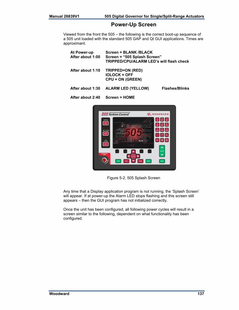
Manual 26839V1 505 Digital Governor for Single/Split-Range Actuators
Woodward 137
Power-Up Screen Viewed from the front the 505 – the following is the correct boot-up sequence of a 505 unit loaded with the standard 505 GAP and Qt GUI applications. Times are approximant.
At Power-up Screen = BLANK /BLACK After about 1:00 Screen = “505 Splash Screen”
TRIPPED/CPU/ALARM LED’s will flash check
After about 1:10 TRIPPED=ON (RED) IOLOCK = OFF CPU = ON (GREEN)
After about 1:30 ALARM LED (YELLOW) Flashes/Blinks
After about 2:40 Screen = HOME
Figure 5-2. 505 Splash Screen Any time that a Display application program is not running, the ‘Splash Screen’ will appear. If at power-up the Alarm LED stops flashing and this screen still appears – then the GUI program has not initialized correctly. Once the unit has been configured, all following power cycles will result in a screen similar to the following, dependent on what functionality has been configured.

505 Digital Governor for Single/Split-Range Actuators Manual 26839V1
138 Woodward
Figure 5-3. Boot-up to HOME Screen Refer to Figure 4.1 for the view of an initial power-up of an unconfigured unit. There is a Screen Saver function that is invoked after a period of inactivity. It is defaulted to 4 hours (adjustable in Service / Screen Settings) – when this comes it a small version of the ‘Splash Screen’ will bounce around on the screen. Press any key to revive the display (maroon keys are recommended). When awaking from screen saver the user login level will be reduced to Operator. This also is adjustable in Service / Screen Settings if desired, it can be changed to awaken to Monitor.
Control Mode Architecture Basic control program architecture is illustrated in Figure 5-1. The 505’s normal operating architecture divides the control into two states. Run – which includes Operation and Calibration modes Program - Configuration mode Pressing the MODE key at anytime will open the Login and Mode Screen The Configuration Mode is used to configure the 505 for the specific application and set all operating parameters (see Chapter 4). In this mode the control will issue an IOLOCK (LED) and the state of all Outputs from the 505 are disabled. This means that all Relays are de-energized and all Analog/Driver outputs are at zero current. Initially all 505’s must be placed in this mode to enter a valid configuration of the I/O and functions desired for the specific turbine application. The Calibration Mode is used after the configuration of the 505 is complete. It is used to perform calibration of signals, verification of speed signals and the forcing of outputs of the control in preparation to run the turbine. All I/O is functional in this state. To enter this mode the turbine must be TRIPPED (LED). The Operation Mode is used to view operating parameters and run the turbine. This is the typical mode the control uses and is the default mode it enters at Power-up. All I/O is functional in this state. The turbine may be either running or not running in this mode.

Manual 26839V1 505 Digital Governor for Single/Split-Range Actuators
Woodward 139
Figure 5-4. Control Mode Architecture
User Login Levels Pressing the MODE key at anytime will open the Login and Mode Screen
Figure 5-5. Mode Screen

505 Digital Governor for Single/Split-Range Actuators Manual 26839V1
140 Woodward
Monitor – (logout to enter this) Even Keypad Green keys inhibited Operator – (passwords are provided in Vol 2 Appendix C) Intended for normal turbine operation – default mode Screen saver initiates to this level Service – (passwords are provided in Vol 2 Appendix C) Allows tuning of parameters, while turbine is running (PID dynamics) and entering of Calibration Mode Configure – (passwords are provided in Vol 2 Appendix C) Highest user authority / can enter any Mode
EMERGENCY STOP is always available in all modes and logins as it has direct H/W action to open the Actuator circuits.
To Login –
1. Press the LOGIN button 2. ** Navigate so the Login or Password field is highlighted (in-focus) 3. Press Enter on the Navigation Cross 4. Use the keypad to enter the text field (hold key down to scroll options) 5. Press Enter on the Navigation Cross – to accept your entry
** Or you can navigate to the Autofill buttons and press Enter – it will auto-populate the Login information so you only need to enter the Password.
Navigation This is NOT a touchscreen! Due to quality, robustness, screen cleanliness and long term reliability concerns Woodward chose not to implement a touchscreen directly on this product. Using the RemoteView tool a user can take advantage of either a mouse device or a touchscreen on an external computer, but for navigation and selection directly on the 505 display, buttons and an IN-Focus highlighter indication are used. In general the maroon buttons provide navigation from page-to-page and throughout the components on a page. Most of the navigation is done with the Navigation cross.
Figure 5-6. Navigation Cross

Manual 26839V1 505 Digital Governor for Single/Split-Range Actuators
Woodward 141
1. Use the “Arrow” buttons to move the IN-Focus highlighter to the desired page
2. Press the “Enter” button to launch the page selected 3. Press the “ESC” (Escape) button to go back 1 page from current page 4. Press the “HOME” button to return to the main menu Note: If in Service
or Configure menu a second press of HOME will return to the Operational Home screen
Figure 5-7. Service Menu showing “Speed Control” IN-Focus
Page Organization There are 3 primary menu lists that organize the access to all of the information that is available on the display. These menu lists are available at all times. The user simply uses the navigation cross to Focus on the desired page and press Enter, or use the the Black ‘soft keys’ (no Focus needed). Run/Operation menus - The HOME page contains the Run/Operation menus and is automatically updated to match the configuration of the control. Service menus - The Service ‘HOME’ page contains navigation buttons to all of the service related parameters and special feature of the control and it too is is automatically updated to match the configuration of the Configuration menus - The Configuration ‘HOME’ page contains navigation buttons to all features and options of the 505. When the unit is in Configure Mode (IOLOCK) the background of all pages will be a blue gradient as shown below, in addition to the status in the upper right.
Figure 5-8. Configuration Menu – Operation Mode (View only)

505 Digital Governor for Single/Split-Range Actuators Manual 26839V1
142 Woodward
Figure 5-9. Configuration Menu – Configuration Mode (Edit) Refer to chapter 1 for more details about all of the keys – below are some general reminders about the keypad functions
Green keys – initiate operational commands Red keys - navigate or enter values via the alpha numeric keys Black keys – are software dependent and may do either, they never require ‘IN-Focus’ the command shown in above the key is always available
Start and Stop Keys – always require a Confirmation and user must be logged-in at appropriate User level (Operator or greater)
EMERGENCY STOP is always available in all modes and logins as it has direct H/W action to open the Actuator circuits.
When entering string text from the keypad, holding down the key will make is slowly cycle through the characters available on that key. Releasing the key will select the character shown at that time.

Manual 26839V1 505 Digital Governor for Single/Split-Range Actuators
Woodward 143
Overview Screen
Figure 5-10. Overview Screen The Overview screen will adapt to the configuration of the 505 and show all configured options. During normal run operation, this screen should provide the user with all of the primary turbine parameter values and operational status. The menu bar functions will allow the user to use typical operational commands related to the control loop selected – such as directly entering a setpoint or enabling or disabling a controller while remaining on the Overview page
Speed Control Screen
Figure 5-11. Speed Control Screen

505 Digital Governor for Single/Split-Range Actuators Manual 26839V1
144 Woodward
The Speed Control screen will adapt to the configuration of the 505 and show all configured options. During normal run operation, this screen provides the user with all details that are related to the turbine when operating in speed control. The menu bar functions will allow the user to access a number of other screens that are related to speed control, such as directly entering a setpoint, access to the valve limiter feature, adjusting speed control dynamic settings, enabling or disabling a remote speed setpoint or performing an Overspeed test. For generator units the breaker status of the breakers is shown and the menu bar will give the user access to Enabling the synchronizer.
Valve Demand Screen
Figure 5-12. Valve Demand Screen The Valve Demand screen will adapt to the configuration of the 505 and show all configured options that can affect the final output demand to the valve. During normal run operation, this screen provides the user with a clear picture of what control or ramp is controlling the valve demand output. The Low Signal Select (LSS) bus will output the lowest value seen at its inputs. The valve logic box represents options that may be use to adjust this value (such as valve linearization and/or pressure compensation) prior to output to the HP valve. If these options are not used, the HP valve demand output will always equal the LSS value. During normal operation the Valve Limiter setting is at 100% and not limiting. Typically, the only time this parameter is adjusted is during a start sequence or to troubleshoot system dynamics problems. The menu bar will allow the user to access the valve limiter setpoint and the manual valve demand (if configured for use).

Manual 26839V1 505 Digital Governor for Single/Split-Range Actuators
Woodward 145
Controllers Screen
Figure 5-13. Controllers Screen The Controllers screen will adapt to the configuration of the 505 and show all configured options. During normal run operation, this screen provides the user with information similar to the Overview, but in a graphical gauge view. It provides larger values for distance viewing and control PID information which is useful for monitoring when the 505 is near transition points between controllers or limiters. The menu bar functions will allow the user to use typical operational commands related to the control loop selected – such as directly entering a setpoint or enabling or disabling a controller while remaining on the Controllers page
Cascade Control Screen
Figure 5-14. Cascade Control Screen

505 Digital Governor for Single/Split-Range Actuators Manual 26839V1
146 Woodward
The Cascade Control screen will adapt to the configuration of the 505. During normal run operation, this screen provides the user with all details that are related to the cascade control loop. The cascade control output determines the setpoint for the speed control. This allows the 505 to vary the speed control setpoint as it relates to another process variable selected by the user. The menu bar functions will allow the user to access a number of other screens that are related to cascade control, such as directly entering a setpoint, access to the valve limiter, or adjusting cascade control dynamic settings.
Auxiliary Control Screen
Figure 5-15. Auxiliary Control Screen The Auxiliary Control screen will adapt to the configuration of the 505. During normal run operation, this screen provides the user with all details that are related to the auxiliary control loop. The auxiliary control output goes to the LSS bus and can directly affect the HP valve demand output. This can be configured as a limiter or a controller. If it is a limiter it will always be enabled and provide protection related to the process variable being used for this function. When configured as a controller it will disable the speed PID whenever it’s enabled. The menu bar functions will allow the user to access a number of other screens that are related to auxiliary control, such as directly entering a setpoint, access to the valve limiter, or adjusting auxiliary control dynamic settings. The Auxiliary 2 Control is identical to the Auxiliary Control with the exception that it can only be used as a limiter.

Manual 26839V1 505 Digital Governor for Single/Split-Range Actuators
Woodward 147
Analog Input Summary Screen
Figure 5-16. Analog Input Summary Screen The Analog Input Summary screen will display the status of all channels available on the 505 hardware. The fault status, function, device tag, engineering value and units are shown for each channel as well as navigation buttons for each channel that take the user to a page showing all parameters available for that input. The menu bar functions will allow the user to access the detailed page of the speed input signals
Contact Input Summary Screen
Figure 5-17. Contact Input Summary Screen

505 Digital Governor for Single/Split-Range Actuators Manual 26839V1
148 Woodward
The Contact Input Summary screen will display the status of channels available on the 505 hardware. The fault status, function, and device tags are shown for each channel as well as navigation buttons for each channel that take the user to a page showing all parameters available for that input. The contact input summary is broken into 3 pages and the menu bar contains navigation buttons to view all the channels
Analog Output Summary Screen
Figure 5-18. Analog Output Summary Screen The Analog Output Summary screen will display the status of all channels available on the 505 hardware. The fault status, function, device tag, engineering value and units are shown for each channel as well as navigation buttons for each channel that take the user to a page showing all parameters available for that output.

Manual 26839V1 505 Digital Governor for Single/Split-Range Actuators
Woodward 149
Relay Output Summary Screen
Figure 5-19. Relay Output Summary Screen The Relay Output Summary screen will display the status of all channels available on the 505 hardware. The coil status, function, and device tag are shown for each channel as well as navigation buttons for each channel that take the user to a page showing all parameters available for that output.
Actuator Driver Summary Screen
Figure 5-20. Actuator Driver Summary Screen The Actuator Driver Summary screen will display the status of the 2 channels available on the 505 hardware. The fault status, function, current value (in mA), engineering value and units are shown for each channel as well as navigation buttons for each channel that take the user to a page showing all parameters available for that input.

505 Digital Governor for Single/Split-Range Actuators Manual 26839V1
150 Woodward
Starting Procedures (Start Curve Screen)
Figure 5-21. HOME Menu showing “Startup Curve” IN-Focus Refer to the turbine manufacturer’s operating procedures for complete information on turbine start up, and Chapter 3 of this manual for a step by step procedure, depending on the start mode selected. The following is a typical start- up procedure:
The engine, turbine, or other type of prime mover should be equipped with an overspeed shutdown device to protect against runaway or damage to the prime mover with possible personal injury, loss of life, or property damage. The overspeed shutdown device must be totally independent of the prime mover control system. An overtemperature or overpressure shutdown device may also be needed for safety, as appropriate.
1. Press the RESET key to clear all alarms and trips. If the 505’s RESET
CLEARS TRIP setting is programmed "YES", the 505's shutdown relay will reset or energize upon pressing the RESET key after a shutdown. If the RESET CLEARS TRIP OUTPUT setting is programmed "NO", the 505's shutdown relay will reset or energize upon pressing the Reset key ONLY after all trip conditions are cleared.
2. Press the START key and Confirm, to initiate the selected start-up mode. This will function from any screen, but it is recommended to be on the Startup Curve page during the turbine startup. It will automatically be matched to show the correct information relative to the start sequence that has been configured. If a semi-automatic start mode is configured, the valve limiter must be manually increased to open the control valve. A ‘Start Perm Not Closed’ alarm will be issued if the application is using
a Start Permissive contact input and this contact input was not closed when the RUN command was issued.
3. After the selected start-up mode has been performed, the turbine will operate at the minimum or idle speed setting. The 505’s speed set point will move to minimum governor speed unless an idle speed is programmed. The Idle/Rated or Auto Start Sequence functions must be programmed for the turbine to control at idle speed. An operator at this time may vary turbine speed through the 505's keypad, external switches or communication links.

Manual 26839V1 505 Digital Governor for Single/Split-Range Actuators
Woodward 151
Overspeed Test Function (Speed Control Screen) The 505’s Overspeed Test function allows an operator to increase turbine speed above its rated operating range to periodically test turbine electrical and/or mechanical overspeed protection logic and circuitry. This includes the 505’s internal overspeed trip logic and any external overspeed trip device’s settings and logic. Figure 5-11 shows the screen that is displayed when the ‘Overspeed Test’ key is pressed from the Speed Control page. It shows the permissives required to be able to perform an overspeed test (in the case of a mechanical drive application the Generator Breaker Open is not shown)
Figure 5-22. Overspeed Test Permissives
The engine, turbine, or other type of prime mover should be equipped with an overspeed shutdown device to protect against runaway or damage to the prime mover with possible personal injury, loss of life, or property damage. The overspeed shutdown device must be totally independent of the prime mover control system. An overtemperature or overpressure shutdown device may also be needed for safety, as appropriate.
Overspeed Test Procedure (from the 505 display) Be sure the generator breaker is open or if unit is a generator drive Raise the Speed Set Point to the maximum governor setting If desired, clear the ‘Highest Speed Reached’ value, to record the highest
speed reached during this overspeed test. (Reset Max key) This function has a safety timeout to insure the unit does not run in this
mode unattended. Once the mode is entered, the user must begin to raise the speed within 30 seconds. As long as the user is adjusting the speed the timeout value will be reset.
Timeout value is shown, if it expires the test mode will be aborted and the unit will return to the maximum governor limit

505 Digital Governor for Single/Split-Range Actuators Manual 26839V1
152 Woodward
Figure 5-23. Internal (505) Overspeed Test To perform an Internal Overspeed Test Press the Enable Int Test key and
the above pop-up page will appear. An Alarm will be annunciated that indicates Overspeed Test Enabled
Put the Adjust button in Focus and use the ADJUST key to raise the speed above the normal Max Governor limit.
Once turbine speed reaches the 505’s internal OVERSPEED TRIP (rpm) setting, the 505 will TRIP the turbine
Figure 5-24. External Overspeed Test An external trip test is intended to be used to test the unit’s safety overspeed protection device (in many cases a Woodward ProTech). In this mode the 505 internal overspeed trip will be changed to be just an alarm and the 505 will allow the speed to continue increasing up to the Overspeed Test Limit (rpm). If the 505 speed OR the Setpoint reaches the Overspeed Test Limit it will TRIP To perform an External Overspeed Test Press the Enable Ext Test key and
the above pop-up page will appear. An Alarm will be annunciated that indicates Overspeed Test Enabled
Put the Adjust button in Focus and use the ADJUST key to raise the speed above the normal Max Governor limit.

Manual 26839V1 505 Digital Governor for Single/Split-Range Actuators
Woodward 153
Once turbine speed reaches the 505’s internal OVERSPEED TRIP (rpm) setting, the 505 will trigger an alarm that this has been reached
If the timeout expires while the unit is above the Overspeed Trip setting, but below the Overspeed Test Limit, the 505 will Trip on Overspeed
If the Speed or the Setpoint reach the Overspeed Test Limit the 505 will issue a Trip
In the configuration of Speed Setpoints be sure that the Overspeed Test Limit rpm value is above the expected Overspeed setting of the external safety overspeed protection device.
It is recommended to perform Overspeed Tests from these screens, either at the control (preferred) or via the RemoteView service tool. Alternatively the turbine’s overspeed logic and circuitry can be tested remotely, by programming an Overspeed Test contact input. The Overspeed Test contact functions as the enable external test on the display. When the conditions outlined in the above procedure are met, closing this contact allows the Speed set point to be increased up to the “Overspeed Test limit” setting. The testing procedure is similar to using the OSPD key. An Overspeed Test Enabled relay can be programmed to provide the status feedback that testing is enabled. The Overspeed Test function cannot be performed over the Modbus communications, however, the Overspeed Test Permissive, Overspeed Test In Progress, Overspeed Alarm, and Overspeed Trip indications are available through Modbus.
Stop Key The STOP key is used to perform a controlled/manual turbine shutdown or stop. To perform a Manual Shutdown, press the STOP key and confirm from the keypad or close the Controlled Shutdown contact input (if programmed) or select Controlled Shutdown from a Modbus communications link. Once initiated, the display dialog box will change to give the user the option to abort the Normal stop sequence. This dialog box will close after 10 seconds, but can be reopened by pressing the STOP key. This function can be also be stopped by opening the contact or selecting Abort Controlled Shutdown from a Modbus communications link.
Alarm Summary The ALARM screen is always available with the VIEW button under the ALARM LED. When an alarm is detected, it gets latched in the event logic, the Alarm relay is energized, and the ALARM LED illuminates (Yellow). The cause of the event will be indicated with an Event ID, description and time/date stamp on the Alarm Summary page. The list will always place the first event at the top of the list, if more than one alarm condition is present they will all be listed with their corresponding time stamp. To clear any alarms that are no longer present, press the RESET key, close the Reset contact input, or select Reset from either Modbus communications link. If the cause of the event has been corrected the alarm will clear, it not it will remain and the time-stamp will remain unchanged.

505 Digital Governor for Single/Split-Range Actuators Manual 26839V1
154 Woodward
Figure 5-25. ALARM Screen Each individual alarm condition is available through the Modbus links to monitor the control status. A common alarm indication is also provided. Relay indications can be programmed to indicate a 505 Common Alarm, in addition to the dedicated Alarm Relay output. The table below lists all the potential alarm conditions and their Event ID. Event ID DESCRIPTION MEANING 1 Speed Probe #1 Failed Speed probe #1 failure—(< Failed Speed Level
or 1 Vrms)
2 Speed Probe #2 Failed Speed probe #2 failure—(< Failed Speed Level or 1 Vrms)
3 Remote Spd Input Failed Remote Speed Setpt analog input failure (> 22 mA or < 2 mA)
4 Sync Input Failed Sync analog input failure detected (> 22 mA or < 2 mA)
5 Load Share Input Failed Load Share analog input failure detected (> 22 mA or < 2 mA)
6 KW Load Input Failed KW analog input failure detected (> 22 mA or < 2 mA)
7 Cascade Input Failed Cascade analog input failure detected (> 22 mA or < 2 mA)
8 Remote Casc Input Failed Remote Cascade Setpt analog input failure (> 22 mA or < 2 mA)
9 AUX Input Failed Auxiliary analog input failure detected (> 22 mA or < 2 mA)
10 Remote AUX Input Failed Remote Aux Setpt analog input failure (> 22 mA or < 2 mA)
11 AUX2 Input Failed Auxiliary 2 analog input failure detected (> 22 mA or < 2 mA)
12 Remote AUX2 Input Failed Remote Aux 2 Setpt analog input failure (> 22 mA or < 2 mA)

Manual 26839V1 505 Digital Governor for Single/Split-Range Actuators
Woodward 155
13 Inlet Press Input Failed Inlet Header Pressure analog input failure detected (> 22 mA or < 2 mA)
14 IH‐A Input press AI FLT Fault indication from hydraulic pressure unit A
15 IH‐B Input press AI FLT Fault indication from hydraulic pressure unit B
16 Feed‐forward input failed Feed-Forward analog input failure detected (> 22 mA or < 2 mA)
17 Remote Droop Fault Remote Droop Setting analog input failure detected (> 22 mA or < 2 mA)
18 Remote KW Setpoint Failed Remote KW Setpt analog input failure (> 22 mA or < 2 mA)
19 Exhaust Press Input Failed Exhaust Pressure analog input failure detected (> 22 mA or < 2 mA)
20 Temp for Hot/Cold Starts Failed reserved ‐ not used
21 HP Valve Feedback Failed HP position FDBK analog input failure detected (> 22 mA or < 2 mA)
22 HP2 Valve Feedback Failed HP2 position FDBK analog input failure detected (> 22 mA or < 2 mA)
23 Isolated PID PV Failed Isolated PV analog input failure detected (> 22 mA or < 2 mA)
24 Rem SP Isolated PID Failed Rem Setpoint for Iso analog input failure detected (> 22 mA or < 2 mA)
25 Customer Input #1 Failed Customer analog input 1 failure detected (> 22 mA or < 2 mA)
26 Customer Input #2 Failed Customer analog input 2 failure detected (> 22 mA or < 2 mA)
27 Customer Input #3 Failed Customer analog input 3 failure detected (> 22 mA or < 2 mA)
28 Start Temperature 1 Failed Start Temp 1 analog input failure detected (> 22 mA or < 2 mA)
29 Start Temperature 2 Failed Start Temp 2 analog input failure detected (> 22 mA or < 2 mA)
30 spare_flt_ai_funct29 reserved ‐ not used
31 spare_flt_ai_funct30 reserved ‐ not used
32 External alarm # 1 External Alarm #1 from contact input
33 External alarm # 2 External Alarm #2 from contact input
34 External alarm # 3 External Alarm #3 from contact input
35 External alarm # 4 External Alarm #4 from contact input
36 External alarm # 5 External Alarm #5 from contact input
37 External alarm # 6 External Alarm #6 from contact input
38 External alarm # 7 External Alarm #7 from contact input
39 External alarm # 8 External Alarm #8 from contact input
40 External alarm # 9 External Alarm #9 from contact input
41 IH‐act1 Failed from BI Fault indication from current-to-hydraulic Actuator 1 (CPC)
42 IH‐act2 Failed from BI Fault indication from current-to-hydraulic Actuator 2 (CPC)
43 HP Actuator Fault (Act1 or 2) HP Actuator fault detected (open or short circuit was sensed)
44 HP2 Actuator Fault (Act1 or 2) HP2 Actuator fault detected (open or short circuit was sensed)

505 Digital Governor for Single/Split-Range Actuators Manual 26839V1
156 Woodward
45 Start Perm Not Closed Run selected while the Start Perm contact in was not closed
46 Mod Comm Link #1 Failed Modbus com link #1 was detected as failed—time out error
47 Mod Comm Link #2 Failed Modbus com link #2 was detected as failed—time out error
48 Mod Comm Link #3 Failed Modbus com link #3 was detected as failed—time out error
49 AO_01 Readback Fault Analog Output Chan 1 readback failure detected (> 22 mA or < 2 mA)
50 AO_02 Readback Fault Analog Output Chan 2 readback failure detected (> 22 mA or < 2 mA)
51 AO_03 Readback Fault Analog Output Chan 3 readback failure detected (> 22 mA or < 2 mA)
52 AO_04 Readback Fault Analog Output Chan 4 readback failure detected (> 22 mA or < 2 mA)
53 AO_05 Readback Fault Analog Output Chan 5 readback failure detected (> 22 mA or < 2 mA)
54 AO_06 Readback Fault Analog Output Chan 6 readback failure detected (> 22 mA or < 2 mA)
55 Chassis Summary Alarm 1‐ Display Backlight Fault2‐ CPU OS fault 3‐ 505 Internal temp is high (> 70 deg C) 4‐ Unit Calibration Fault (Factory Calibration)
56 Turbine Tripped Turbine is tripped alarm indication
57 Overspeed Turbine overspeed alarm
58 Overspeed Test Enabled Overspeed Test mode is Active
59 TIE Breaker Opened Utility Tie breaker was opened after it was closed
60 GEN Breaker Opened Generator breaker was opened after it was closed
61 Tie Open / No Auxiliary Utility Tie breaker was opened when Auxiliary was active
62 Gen Open / No Auxiliary Generator breaker was opened when Auxiliary was active
63 Tie Open / No Cascade Utility Tie breaker was opened when Cascade was active
64 Gen Open / No Cascade Generator breaker was opened when Cascade was active
65 Tie Open / No Remote Util. Tie breaker was opened when Remote Spd Setpt was active
66 Gen Open / No Remote Generator breaker was opened when Remote Spd Setpt was active
67 Stuck In Critical Band Turbine is stagnating within critical speed window
68 505 Display Comm Fault GAP to Display communication failed
69 HP Valve Pos Fdbk Diff ALM HP Demand versus Feedback Difference
70 HP2 Valve Pos Fdbk Diff ALM HP2 Demand versus Feedback Difference
71 Limiter in Control reserved ‐ not used
72 Inlet Steam Pressure Lvl1 ALM Inlet Steam Pressure passed alarm level 1 limit
73 Inlet Steam Pressure Lvl2 ALM Inlet Steam Pressure passed alarm level 2 limit
74 Exh Steam Pressure Lvl1 ALM Exhaust Steam Pressure passed alarm level 1 limit

Manual 26839V1 505 Digital Governor for Single/Split-Range Actuators
Woodward 157
75 Exh Steam Pressure Lvl2 ALM Exhaust Steam Pressure passed alarm level 2 limit
76 Selected PV 1 Level 1 ALM Signal Monitoring #1 passed alarm level 1 limit
77 Selected PV 1 Level 2 ALM Signal Monitoring #1 passed alarm level 2 limit
78 Selected PV 2 Level 1 ALM Signal Monitoring #2 passed alarm level 1 limit
79 Selected PV 2 Level 2 ALM Signal Monitoring #2 passed alarm level 2 limit
80 Selected PV 3 Level 1 ALM Signal Monitoring #3 passed alarm level 1 limit
81 Selected PV 3 Level 2 ALM Signal Monitoring #3 passed alarm level 2 limit
82 Tunable Alarm reserved ‐ not used
83 Tie Open / No Auxiliary 2 Utility Tie breaker was opened when Auxiliary 2 was active
84 Gen Open / No Auxiliary 2 Generator breaker was opened when Auxiliary 2 was active
85 Actuator 1 Readout Fault Actuator Driver Chan 1 readback failure detected
86 Actuator 2 Readout Fault Actuator Driver Chan 2 readback failure detected
87 CAN1_DVP1 Summary ALM Summary Alarm from VariStroke device DVP1
88 CAN1_DVP2 Summary ALM Summary Alarm from VariStroke device DVP2
89 HP Actuator Fault (DVP1 or 2) HP Actuator fault detected (CAN1 link to VariStroke)
90 HP2 Actuator Fault (DVP1 or 2) HP2 Actuator fault detected (CAN1 link to VariStroke)
91 Comm Link to DSLC2 Failed Digital Comm Link to DSLC‐2 Failed
92 KW Load AI Failed Backup KW signal is faulted (AI or digital link)
93 Turbine Maintenance Interval Alm Turbine Run Hours Reached Maintenance Interval
94 Start Temperature #1 Override Active
Override of Start Temperature #1 Signal is Active
95 Start Temperature #2 Override Active
Override of Start Temperature #2 Signal is Active
96 Comm Link to easYgen Failed Digital Comm Link to easYgen Failed
97 Comm Link to LS‐5 Failed Digital Comm Link to LS‐5 Failed
98 Comm Link to MFR300 Failed Digital Comm Link to MFR300 Failed
99 Comm Link to HiProtec Failed Digital Comm Link to HiProtec Failed
100 MPU1 Failed Open Wire Test Open wire detected on speed signal circuit channel 1
101 MPU2 Failed Open Wire Test Open wire detected on speed signal circuit channel 2
102 Internal HW Simulation Enabled Internal 505 SIMULATION Mode Active
103 Pressure Compensation Curve Error
Pressure Comp curve error on X-Y points
104 Actuator Linearization Curve Error Output valve curve error on X-Y points
105 Spare_105
Table 5-1. ALARM Messages

505 Digital Governor for Single/Split-Range Actuators Manual 26839V1
158 Woodward
Shutdown Summary The Shutdown Summary screen is always available with the VIEW button under the TRIPPED LED. When a trip is detected, it gets latched in the event logic, the Trip relay is de-energized, all steam valve demand outputs go to zero, and the TRIPPED LED illuminates (Red). The cause of the event will be indicated with an Event ID, description and time/date stamp on the Shutdown Summary page. The list will always place the first event at the top of the list, if more than one trip condition is present they will all be listed with their corresponding time stamp. To clear any shutdowns that are no longer present, press the RESET key, close the Reset contact input, or select Reset from either Modbus communications link. If the cause of the event has been corrected the event will clear, it not it will remain and the time-stamp will remain unchanged.
Figure 5-26. Shutdown Summary Screen The table below lists all the potential shutdown conditions.
Event ID DESCRIPTION MEANING
1 External Trip Input 1 External Trip contact input was opened
2 Emergency Stop Button Front Panel Display Emergency Stop was pressed
3 Overspeed Turbine overspeed was sensed
4 All Speed Probes Failed Loss of all speed probes was sensed
5 HP Actuator Fault HP Actuator fault detected (an open or short circuit was sensed)
6 HP2 Actuator Fault HP2 Actuator fault detected (an open or short circuit was sensed)
7 Aux Input Failed Aux analog input failure detected (> 22 mA or < 2 mA)
8 Power Up Trip 505 lost power or the Configuration mode was exited
9 Normal Shutdown Complete Controlled shutdown was performed and completed
10 Trip Command from Modbus Modbus communication link trip was commanded
11 Unit in Calibration Mode 505 is in Calibration Mode
12 Configuration Error 505 has a configuration error
13 Tie Breaker Opened Utility tie breaker was opened after it was closed
14 GEN Breaker Opened Generator breaker was opened after it was closed

Manual 26839V1 505 Digital Governor for Single/Split-Range Actuators
Woodward 159
15 External Trip 2 External Trip #2 contact input was opened
16 External Trip 3 External Trip #3 contact input was opened
17 External Trip 4 External Trip #4 contact input was opened
18 External Trip 5 External Trip #5 contact input was opened
19 External Trip 6 External Trip #6 contact input was opened
20 External Trip 7 External Trip #7 contact input was opened
21 External Trip 8 External Trip #8 contact input was opened
22 External Trip 9 External Trip #9 contact input was opened
23 External Trip 10 External Trip #10 contact input was opened
24 HP Ramp at Max/No Speed HP Valve Limiter ramp is at Max but no speed is detected
25 Actuator Scaling Min>Max For Act 1&2 the Min current setting must be Less than Max current setting (use Invert option to reverse these)
26 SPARE reserved for future use
27 SPARE reserved for future use
28 SPARE reserved for future use
29 Inlet Stm Pressure Level2 TRIP Inlet Steam Pressure passed trip level limit
30 EXH Stm Pressure Level2 TRIP Exhaust Steam Pressure passed trip level limit
31 Selected PV 1 Level 2 TRIP Customer Monitor Signal 1 passed trip level limit
32 Selected PV 2 Level 2 TRIP Customer Monitor Signal 2 passed trip level limit
33 Selected PV 3 Level 2 TRIP Customer Monitor Signal 3 passed trip level limit
34 Tunable Trip reserved for simulation use
35 Configuration Mode (IO Lock) 505 is in Configuration Mode (in IOLOCK)
36 Aux 2 Input Failed Aux 2 analog input failure detected (> 22 mA or < 2 mA)
37 Open Wire on MPUs Open wires detected on all MPUs
38 spare_38 reserved for future use
39 spare_39 reserved for future use
40 spare_40 reserved for future use
Table 5-2. TRIPPED Messages
Each individual trip condition is available through the Modbus links to monitor the control status. A common trip indication is also provided. Relay indications can be programmed to indicate a 505 Shutdown Condition (energizes for a shutdown condition) or a Trip Relay (de-energizes for a shutdown/trip), in addition to the dedicated Emergency Trip Relay output.

505 Digital Governor for Single/Split-Range Actuators Manual 26839V1
160 Woodward
Speed, Cascade, and Auxiliary Dynamics Adjustments
Dynamic control values are programmed in the configuration mode and adjusted in the RUN (Operation or Service) mode. The Proportional and Integral Gain and the Derivative Ratio dynamic adjustments are available under found under Dynamics pages for each controller (SPEED, CASC, AUX, and AUX2). To adjust the gain settings, the In-Focus highlighter must be on the component value to tune. The In-Focus highlighter is moved using the navigation Cross. The ADJUST UP and DOWN keys can then be used to adjust the function In-Focus.
Figure 5-27. Speed Dynamics Adjustment Screen The Speed, Cascade, Auxiliary and Auxiliary 2 controls are PID controllers. The response of each control loop can be adjusted by selecting the dynamics mode as described above. Proportional gain, integral gain (stability), and DR (derivative ratio) are the adjustable and interacting parameters used to match the response of the control loop with the response of the system. They correspond to the P (proportional), I (integral), and D (derivative) terms, and are displayed by the 505 as follows: P = Proportional gain (%) I = Integral gain (%) D = Derivative (determined by DR and I) Tuning P & I Gains Proportional gain must be tuned to best respond to a system transient or step change. If system response is not known, a typical starting value is 5%. If proportional gain is set too high the control will appear to be overly sensitive, and may oscillate with a cycle time of less than 1 second. Integral gain must be tuned gain for best control at steady state. If system response is not known a typical starting value is 5%. If the integral gain is set too high the control may hunt or oscillate at cycles times of over 1 second.

Manual 26839V1 505 Digital Governor for Single/Split-Range Actuators
Woodward 161
For best response the proportional gain and integral gain should be as high as possible. To obtain a faster transient response, slowly increase the proportional gain setting until the actuator or final driver output begins to oscillate or waver. Then adjust the integral gain as necessary to stabilize the output. If stability cannot be obtained with the integral gain adjustment, reduce the proportional gain setting. A well tuned system, when given a step change, should slightly overshoot the control point then come into control. A PID control loop’s gain is a combination of all the gains in the loop. The loop’s total gain includes actuator gain, valve gain, and valve linkage gain, transducer gain, internal turbine gains, and the 505’s adjustable gains. If the accumulated mechanical gain (actuators, valves, valve linkage, etc.) is very high, the 505’s gain must be very low to be added to the system gain required for system stability. In cases where a small change in the 505's output results in a large speed or load change (high mechanical gain) it may not be possible to take the 505's gains low enough to reach stable operation. In those cases the mechanical interface (actuator, linkage, servo, valve rack) design and/or calibration should be reviewed and changed to achieve a gain of one where 0–100% 505 output corresponds to 0–100% valve travel. Dual Dynamics (Speed/Load) The Speed PID has two sets of dynamics, On-Line and Off-Line; each include Proportional Gain, Integral Gain, and Derivative Ratio (DR) variables. There are three cases that determine when the dynamics switch between On-Line and Off- Line: A “Select On-Line Dynamics” contact input is programmed Unit is driving a generator Unit is driving a mechanical drive (not a generator) If a contact input is programmed to “Select On-Line Dynamics”, it has priority regardless of the driven device. When the contact is closed, On-Line dynamics are selected; when open, Off-Line dynamics are selected. If the unit is driving a generator and no “Select On-Line Dynamics” contact input is programmed, the Speed Off-Line dynamics are used by the Speed PID when the generator or utility tie breaker contacts are open. The speed On-Line dynamics are used by the speed PID when the generator and utility tie breaker contacts are closed. If the speed dynamics select contact is programmed, the generator and utility tie contacts do not effect the dynamics selection. If the unit is not driving a generator and no “Select On-Line Dynamics” contact input is programmed, the Speed Off-Line dynamic settings are used when the turbine speed is below minimum governor speed; .On-Line dynamics are used if the turbine speed is above minimum governor speed. If the speed dynamics select contact is programmed, the turbine speed does not effect the dynamics selection. A relay can be programmed to indicate that the On-Line Dynamics mode is selected.

505 Digital Governor for Single/Split-Range Actuators Manual 26839V1
162 Woodward
Cascade/Auxiliary Droop The Cascade and Auxiliary (1 & 2) controllers can be programmed to use droop for control loop stability. If the parameter being controlled (Cascade or Auxiliary) is also being controlled by another device (letdown station, boiler, or other turbine), droop is typically required for control loop stability. If required, no less than 5% droop is recommend for stable operation. Tuning Derivative The value of the Derivative Ratio (DR) term can range from 0.01 to 100. If unsure of the correct value, set the Speed control’s DR term to 5% and the Aux & Cascade controllers’ DR terms to 100%. In order to simplify adjustment of the dynamics, adjusting the integral gain value sets both the I and D terms of the PID controller. The DR term establishes the degree of effect the integral gain value has on the "D" term, and changes the configuration of a controller from input rate sensitive (input dominant) to feedback rate sensitive (feedback dominant) and vice versa. Another possible use of the DR adjustment is to reconfigure the controller from a PID to a PI controller. This is done by adjusting the DR term to its upper or lower limits, depending on whether an input or feedback dominant controller is desired. A DR setting of 1 to 100 selects feedback dominant mode. A DR setting of .01 to 1 selects input dominant mode. A DR setting of .01 or 100 selects a PI only controller, input and feedback
dominant respectively. The change from one of these configurations to the other may have no effect during normal operation, however, it can cause great differences in response when the governor is coming into control. (at start-up, during a full load change, or during transfer of control from another channel). An input dominant controller is more sensitive to the change-of-rate of its input (Speed, Cascade in or Auxiliary in), and can therefore prevent overshoot of the set point better than a feedback dominant controller. Although this response is desirable during a start-up or full load rejections, it can cause excessive control motions in some systems where a smooth transition response is desired. A controller configured as feedback dominant is more sensitive to the change-of- rate of its feedback (LSS). A feedback dominant controller has the ability to limit the rate of change of the LSS bus when a controller is near its set point but is not yet in control. This limiting of the LSS bus allows a feedback dominant controller to make smoother control transitions than an input dominant controller. Tuning Example If the system is unstable, make sure the governor is the cause. This can be checked by closing the valve limiter until it has control of the actuator output. If the governor is causing the oscillation, time the oscillation cycle time. A rule-of- thumb is, if the system’s oscillation cycle time is less than 1 second reduce the Proportional gain term. A rule-of-thumb is, if the system’s oscillation cycle time is greater the 1 second reduce the Integral gain term (proportional gain may need to be increased also).

Manual 26839V1 505 Digital Governor for Single/Split-Range Actuators
Woodward 163
On an initial start-up with the 505, all PID dynamic gain terms will require adjustment to match the respective PID’s response to that of its control loop. There are multiple dynamic tuning methods available that can be used with the 505’s PIDs to assist in determining the gain terms that provide optimum control loop response times (Ziegler Nichols, etc.). Figure 5-19 shows the typical response to a load change when the dynamics are optimally adjusted.
Figure 5-28. Typical Response to Load Change
For additional information on PID settings, refer to Volume 2.

505 Digital Governor for Single/Split-Range Actuators Manual 26839V1
164 Woodward
Chapter 6. Communications
Modbus Communications The 505 control can communicate with plant distributed control systems and/or CRT based operator control panels through Modbus communication ports. There is one serial port that supports RS-232 and RS-485 communications using ASCII or RTU MODBUS transmission protocols. There are 2 ports available for either Modbus UDP or TCP/IP protocol which can be utilized from Ethernet port 1 or 2. Modbus utilizes a master/slave protocol. This protocol determines how a communication network’s master and slave devices establish and break contact, how a sender is identified, how messages are exchanged, and how errors are detected.
Our experience has been that not all serial interfaces on laptops or Desktop PCs work the same. Many USB-to-Serial converters work, but some do not.
To use a 505 Modbus port to monitor and/or operate, check the “Use Modbus” checkbox under the Configurations menu / Communications page. Monitor Only The three Modbus communication ports, are defaulted as read-only. As read-only ports, the 505 can be monitored but not controlled from an external device. By simply connecting a monitoring device, configured to communicate through Modbus, and to the 505’s defaulted protocol settings (parity, stop bits, etc.), this device can be used to monitor all the 505’s controlling parameters, modes, etc. without affecting control. Configuration of the protocol is found on the Communications page under both the Configuration and Service menus. There are options for the serial settings, slave address number and a checkbox to enable write commands. Monitor and Control Once a Modbus port is configured within the 505’s Program Mode, the 505 will accept RUN mode commands from an external network master device (DCS, etc.). This allows a Modbus compatible device to monitor and perform all 505 RUN mode parameters and commands except for the Overspeed Test enable, On- Line/Off-Line Dynamics select, and Override Failed Speed Signal commands. Each Modbus port is independent of the other, and can be used simultaneously. Each only must have its own slave device address and each has its own enable write checkbox. The last command given from any of the ports has priority or is the mode or function selected.

Manual 26839V1 505 Digital Governor for Single/Split-Range Actuators
Woodward 165
Modbus Communication The 505 control supports two Modbus transmission modes. A mode defines the individual units of information within a message and the numbering system used to transmit the data. Only one mode per Modbus network is allowed. The supported modes are ASCII (American Standard Code for Information Interchange), and RTU (Remote Terminal Unit). These modes are defined in the following table. Characteristic ASCII RTU Coding System hexadecimal (uses 8-bit binary ASCII printable binary characters: 0-9, A-F) Start Bits 1 1 Data Bits per Char 7 8 Parity even, odd even, odd or none or none Stop Bits 1, 1.5, or 2 1, 1.5, or 2 Baud Rate 110, 300, 600, 1200 110,300, 600, 1200 1800,2400, 4800, 9600 1800, 2400, 4800, 9600 19200, 38400, or 57600 19200, 38400, or 57600 Error Checking LRC(Longitudinal CRC(Cyclical Redundancy Check) Redundancy Check)
Table 6-1. ASCII vs RTU Modbus In the RTU mode, data is sent in 8-bit binary characters and transmitted in a continuous stream. In the ASCII mode, each binary character is divided into two 4-bit parts (high order and low order), changed to be represented by a hexadecimal equivalent, then transmitted, with breaks of up to 1 second possible. Because of these differences, data transmission with the ASCII mode is typically slower (see Figure 6-1 below).
Figure 6-1. ASCII/RTU Representation of 3 The Modbus protocol allows one master and up to 247 slaves on a common network. Each slave is assigned a fixed, unique device address in the range of 1 to 247. With the Modbus protocol, only the network master can initiate a transaction. A transaction consists of a request from the master to a slave unit and the slave’s response. The protocol and Modbus device number are set in the Program Mode and can be adjusted in the Service Mode, if required. The 505 control is programmed to function as a slave unit only. As a slave unit, the 505 will only respond to a transaction request by a master device. The 505 can directly communicate with a DCS or other Modbus supporting device on a single communications link, or through a multi-dropped network. If multi-dropping is used, up to 246 devices (505s or other customer devices) can be connected to one Master device on a single network. The control address is programmed under the 505’s communications block and can be changed in the service mode, if needed.

505 Digital Governor for Single/Split-Range Actuators Manual 26839V1
166 Woodward
Each message to or from a master has a defined structure called the message “frame”. A frame consists of the slave device address, a code defining the requested data, and error checking information. See Figure 6-2.
Figure 6-2. Modbus Frame Definition
The Modbus function code tells the addressed slaves what function to perform. The following table lists the function codes supported by this control. Modbus Function Codes Code Definition Reference Address 01 Read Digital Outputs 0XXXX (Raise/Lower and Enable/Disable Commands) 02 Read Digital Inputs 1XXXX (Status Indications/Alarms and Trips) 03 Read Analog Outputs 4XXXX 04 Read Analog Inputs 3XXXX (Speed, Setpt, etc.) 05 Write Single Discrete Output 0XXXX (Raise/Lower and Enable/Disable Commands) 06 Write Single Register 4XXXX (Enter Setpt Directly) 08 Loopback Diagnostic Test N/A (Subfunction 0 only) 15 Write Digital Outputs 0XXXX 16 Write Analog Outputs 4XXXX
Table 6-2. Modbus Function Codes When a Modbus message is received, it is checked for any errors or invalid data. If there is invalid data in the message, an error code is sent back to the master and the control issues an alarm message. The error codes are defined in the following table. The exception error status and respective error codes can be viewed on the Communication pages under the Service Menu. If the control has not received a message for the configured time-out period, the control will alarm with an error message, but no message is sent to the master. This time-out is defaulted to 2 seconds and only applies to units using both monitor and control (adjustable through the Service Menu).

Manual 26839V1 505 Digital Governor for Single/Split-Range Actuators
Woodward 167
Modbus Slave Exception Error Codes
Error Error Code Sent Code Message To Master Description 0 No Error 0 No Error 1 Bad Modbus function 1 The specified function is not supported for
this control. 2 Bad Modbus data address 2 The Modbus value addressed is not valid
for this control. 3 Bad Modbus data value 3 Too many values requested or the on/off
indicator in function code 5 is invalid. 9 Bad Modbus checksum None Message checksum did not match. 10 Bad Modbus message None Message could not be decoded. N/A Lost Modbus link None No messages received for the configured
time-out period
Table 6-3. Modbus Error Codes
Port Adjustments Before the 505 will communicate with the master device, the communication parameters must be verified. These values are set in the Configure Mode and can be adjusted, if required, from the Service Mode. Modbus Communication Port Adjustments Parameter Adjustment Range Baud Rate 110 TO 57600 Parity NONE, ODD or EVEN Stop Bits 1 TO 2 Driver RS-232, RS-422, or RS-485
505 Control Modbus Addresses The Modbus communication ports in the 505 control are programmed for unique Modbus addresses. A complete listing of these addresses for your application is located at the end of this section in the manual. The Modbus address listing consists of Boolean Writes, Boolean Reads, Analog Reads, and Analog Writes. The Boolean reads and writes are also referred to as input and holding coils. The analog reads and writes are also referred to as input registers and holding registers. All values that can be addressed by Modbus are considered to be discrete and numeric. The discrete values are a 1 bit binary, on or off value and the numerics are 16 bit values. Discrete values are sometimes referred to as coils or digitals and numerics are referred to as registers or analogs. All read/write registers are interpreted by the 505 as signed 16 bit integer values. Since Modbus can only handle integers, values that require a decimal point in the Modbus Master Device are multiplied by a scaling constant before being sent by 505. See Tables 6-7 and 6-8 for defaulted communication constants and ranges. The maximum number of discretes and registers that can be transmitted in one packet is dependent on each implementation of Modbus. The following table defines these limits.
Mode Of Max Max Transmission Discretes Registers ASCII 944 59 RTU 1188 118
Table 6-4. Maximum Modbus Discrete and Analog Values

505 Digital Governor for Single/Split-Range Actuators Manual 26839V1
168 Woodward
Boolean Writes (Holding Coils) Holding coils are logical signals that are both readable from and writable to the 505 control. An example of a Boolean write value would be raise or lower commands. A logical true denoted by the value 1 will cause the command listed in the description to be executed. For example, if a 1 is written to address 0:0010 and this corresponded to a speed raise command, the manual speed set point will increase until a 0 is written to address 0:0010. The 505 control supports function codes 1, 5, and 15. These correspond to reading selected holding coils, writing to a single holding coil, and writing to multiple holding coils, respectively. The holding coils available are listed in Table 6-5. Boolean Reads (Input Coils) Input coils are logical signals that are readable from, but not writable to, the 505 control. An example of an Boolean read value would be a turbine trip status indication. The input coil will have the value 1 if the statement in the description column is true and a 0 if false. The `1:’ term in the address identifies an input coil. The 505 control supports Modbus function code 2, which involves reading selected input coils. The input coils available are listed in Table 6-6. Analog Reads (Input Registers) Input registers are analog values that are readable from, but not writable to, the 505 control. An example of an analog read value would be turbine speed. The values of the input registers are stored internal to the control as floating point numbers representing engineering units (kPa or rpm). The values that are transmitted are integer values ranging from -32767 to +32767. Since Modbus can only handle integers, values that have a decimal point are multiplied by a constant before being sent by Modbus. For example, these input registers may be listed as the Modbus value `x100’ or `x10’ under the description heading to denote the value is multiplied by a scaling constant. This will allow transmission of decimal parts of a unit if this is necessary for better resolution. See the 505 Service mode for defaulted communication constants and ranges. The 505 control supports Modbus function code 4, which involves reading selected input registers. The input registers available are listed in Table 6-7. Analog Writes (Holding Registers) Holding registers are analog values that are writable to the 505 control. These values can also be read from by a device performing error checking. An example of an analog write value would be a direct speed set point value as opposed to raise and lower commands. The value of the holding registers are also stored in the control as numbers representing engineering units (psi or rpm). The 505 control supports Modbus function codes 3, 6, and 16. These correspond to reading selected holding registers, writing to a single holding register, and writing to multiple holding registers, respectively. The holding registers available are listed in Table 6-8. The following tables give the address and description of all Boolean and analog, reads and writes:

Manual 26839V1 505 Digital Governor for Single/Split-Range Actuators
Woodward 169
Addr Description Addr Description
0:0001 Emergency Shutdown 0:0048 De-Energize Relay 3 0:0002 Emergency Shutdown Acknowledge 0:0049 Energize Relay 4 0:0003 Controlled Shutdown 0:0050 De-Energize Relay 4 0:0004 Abort Controlled Shutdown 0:0051 Energize Relay 5 0:0005 System Reset 0:0052 De-Energize Relay 5 0:0006 Start / Run 0:0053 Energize Relay 6 0:0007 Manual Open VLV Limiter 0:0054 De-Energize Relay 6 0:0008 Manual Close VLV Limiter 0:0055 0:0009 Lower Speed Setpoint 0:0056 0:0010 Raise Speed Setpoint 0:0057 0:0011 Go To Rated (Idle / Rated) 0:0058 0:0012 Go To Idle (Idle / Rated) 0:0059 0:0013 Halt Auto Start Seq 0:0060 0:0014 Continue Auto Start Seq 0:0061 0:0015 Enable Remote Speed Setpoint Control 0:0062 0:0016 Disable Remote Speed Setpoint Control 0:0063 0:0017 Go To Modbus Entered Speed Setpt 0:0064 0:0018 Spare 0:0065 0:0019 Arm Frequency Control 0:0066 0:0020 Disarm Frequency Control 0:0067 0:0021 Sync Enable 0:0068 0:0022 Sync Disable 0:0069 0:0023 Enable Cascade Control 0:0070 * Enable Droop Setpoint change 0:0024 Disable Cascade Control 0:0071 * Disable Droop Setpoint change 0:0025 Lower Cascade Setpoint 0:0072 * Enable Speed Forwarding 0:0026 Raise Cascade Setpoint 0:0073 * Disable Speed Forwarding 0:0027 Enable Remote Cascade Setpoint Control 0:0074 0:0028 Disable Remote Cascade Setpoint Control 0:0075 Momentarily Energize Relay 1 0:0029 Go To Modbus Entered Cascade Setpt 0:0076 Momentarily Energize Relay 2 0:0030 Spare 0:0077 Momentarily Energize Relay 3 0:0031 Enable Aux Control 0:0078 Momentarily Energize Relay 4 0:0032 Disable Aux Control 0:0079 Momentarily Energize Relay 5 0:0033 Lower Aux Setpoint 0:0080 Momentarily Energize Relay 6 0:0034 Raise Aux Setpoint 0:0081 Enable Aux 2 Control 0:0035 Enable Remote Aux Setpoint Control 0:0082 Disable Aux 2 Control 0:0036 Disable Remote Aux Setpoint Control 0:0083 Lower Aux 2 Setpoint 0:0037 Go To Modbus Entered Auxiliary Setpt 0:0084 Raise Aux 2 Setpoint 0:0038 Spare 0:0085 Enable Remote Aux 2 Setpoint Control0:0039 Select Remote Ctrl (Remote/Local) 0:0086 Disable Remote Aux 2 Setpoint Control0:0040 Select Local Ctrl (Remote/Local) 0:0087 Go To Modbus Entered Auxiliary 2
Setpt 0:0041 Spare 0:0088 Enable Remote KW Setpoint Control 0:0042 Modbus Alarm Acknowledge 0:0089 Disable Remote KW Setpoint Control 0:0043 Energize Relay 1 0:0090 Isolated Controller SP Raise 0:0044 De-Energize Relay 1 0:0091 Isolated Controller SP Lower 0:0045 Energize Relay 2 0:0092 Select Hot Start 0:0046 De-Energize Relay 2 0:0093 Select Cold Start 0:0047 Energize Relay 3
Table 6-5. Boolean Write Addresses

505 Digital Governor for Single/Split-Range Actuators Manual 26839V1
170 Woodward
Addr Description Addr Description
1:0001 Alarm - MPU #1 Failed 1:0181 Idle/Rated Start Configured 1:0002 Alarm - MPU #2 Failed 1:0182 Auto Start Sequence Configured 1:0003 Alarm - Cascade Input Failed 1:0183 Inlet Pressure Configured 1:0004 Alarm - Aux Input Failed 1:0184 Remote Control Configured 1:0005 Alarm - KW Input Failed 1:0185 Loadsharing Configured 1:0006 Alarm - Sync Input Failed 1:0186 HP2 Configured 1:0007 Alarm - Inlet Press Input Failed 1:0187 Gen Set Configured 1:0008 Alarm - Remote Speed Input Failed 1:0188 Cascade Control Configured 1:0009 Alarm - Remote Cascade Input Failed 1:0189 Remote Cascade Configured 1:0010 Alarm - Remote Aux Input Failed 1:0190 Aux Control Configured 1:0011 Alarm - Loadshare Input Failed 1:0191 Remote Aux Configured 1:0012 Alarm - HP Actuator Failed 1:0192 Enables Mod Port1 In Local 1:0013 Alarm - HP2 Actuator Failed 1:0193 Start Permissive Configured 1:0014 Alarm - Start Permissive Not Met 1:0194 Frequency Arm/Disarm Configured 1:0015 Alarm - Communication Link #1 Failed 1:0195 Frequency Control Configured 1:0016 Alarm - Communication Link #2 Failed 1:0196 MPU 2 Configured 1:0017 Alarm - Generator Breaker Open 1:0197 Local/Remote Configured 1:0018 Alarm - Turbine Trip 1:0198 Local Trip Enabled 1:0019 Alarm - Tie Breaker Open 1:0199 Casc Tracking Configured 1:0020 Alarm - Overspeed Alarm 1:0200 KW Signal OK 1:0021 Alarm - Tie Breaker Open / No Aux 1:0201 * Spare E 1:0022 Alarm - Gen Breaker Open / No Aux 1:0202 * Spare E 1:0023 Alarm - Tie Breaker Open / No Casc 1:0203 * Spare E 1:0024 Alarm - Gen Breaker Open / No Casc 1:0204 * Spare E 1:0025 Alarm - Tie Breaker Open / No Remote 1:0205 * Spare E 1:0026 Alarm - Gen Breaker Open / No Remote 1:0206 * Spare E 1:0027 Alarm - Stuck in Critical Alarm 1:0207 * TRUE = NEW 505 R 1:0028 * Alarm - spare E 1:0208 FALSE = 505D, TRUE = 505XT 1:0029 * Alarm - spare E 1:0209 * External Alarm 7 1:0030 * Alarm - spare E 1:0210 * External Alarm 8 1:0031 * Alarm - spare E 1:0211 * External Alarm 9 1:0032 * External Alarm 1 1:0212 IH-act1 Failed from BI 1:0033 * External Alarm 2 1:0213 IH-act2 Failed from BI 1:0034 * External Alarm 3 1:0214 * Tunable ALM 1:0035 * External Alarm 4 1:0215 * IH-A Pressure Input Failed 1:0036 * External Alarm 5 1:0216 * AI FW Fault 1:0037 * External Alarm 6 1:0217 * Remote Droop fault 1:0038 CTC Alarm latch 1:0218 * Hwr com1 fault 1:0039 Modbus Alarm Acknowledge 1:0219 SPARE 1:0040 Alarm Exists (Common Alarm Indication) 1:0220 SPARE 1:0041 Trip - External Trip 1:0221 SPARE 1:0042 Trip - ESD Button 1:0222 * Trip - External Trip 10 1:0043 Trip - Overspeed Trip 1:0223 * SD HP max 1:0044 Trip - Loss of Speed Signals 1:0224 SPARE 1:0045 Trip - HP Actuator Fault 1:0225 SPARE 1:0046 Trip - HP2 Actuator Fault 1:0226 SPARE 1:0047 Trip - Aux Input Failed 1:0227 SPARE 1:0048 Trip - External Trip 2 1:0228 * Tunable SD 1:0049 Trip - External Trip 3 1:0229 SPARE 1:0050 Trip - Modbus Link #1 Trip 1:0230 SPARE 1:0051 SPARE 1:0231 SPARE 1:0052 SPARE 1:0232 SPARE 1:0053 Trip - Tie Breaker Open 1:0233 Controlled Stop In Progress 1:0054 Trip - Gen Breaker Open 1:0234 SPARE 1:0055 Trip - Power up 1:0235 SPARE 1:0056 Trip - Manual Stop 1:0236 SPARE 1:0057 Trip - External Trip 4 1:0237 SPARE 1:0058 Trip - External Trip 5 1:0238 SPARE 1:0059 SPARE 1:0239 SPARE

Manual 26839V1 505 Digital Governor for Single/Split-Range Actuators
Woodward 171
1:0060 * Trip - External Trip 6 1:0240 * Spare 1:0061 * Trip - External Trip 7 1:0241 * IH-B Pressure Input Failed 1:0062 * Trip - External Trip 8 1:0242 Alarm - AUX2 Input Failed 1:0063 * Trip - External Trip 9 1:0243 Alarm - Remote AUX2 Input Failed 1:0064 Shutdown Exists (Trip Indication) 1:0244 Alarm - Remote KW Setpoint Failed 1:0065 Modbus ESD Acknowledge Enable 1:0245 Alarm - Exhaust Press Input Failed 1:0066 Moving to Min Setpoint 1:0246 SPARE 1:0067 Ramping to Idle (Idle / Rated) 1:0247 Alarm - HP Valve Feedback Failed 1:0068 Idle / Rated at Idle 1:0248 Alarm - HP2 Valve Feedback Failed 1:0069 Ramping to Rated (Idle / Rated) 1:0249 Alarm - Isolated PID PV Failed 1:0070 At Rated 1:0250 Alarm - Rem SP Isolated PID Failed 1:0071 Auto Seq - Setpt at Idle 1 1:0251 Alarm - Customer Input #1 Failed 1:0072 Auto Seq - Ramp to Idle 2 1:0252 Alarm - Customer Input #2 Failed 1:0073 Auto Seq - Setpt at Idle 2 1:0253 Alarm - Customer Input #3 Failed 1:0074 Auto Seq - Ramp to rated 1:0254 Alarm - Mod Comm Link #3 Failed 1:0075 Auto Seq - At Rated 1:0255 Alarm - AO_01 Readback Fault 1:0076 Speed PID In Control 1:0256 Alarm - AO_02 Readback Fault 1:0077 Speed Sensor 1 Failed Override ON 1:0257 Alarm - AO_03 Readback Fault 1:0078 Speed Sensor 2 Failed Override ON 1:0258 Alarm - AO_04 Readback Fault 1:0079 Overspeed Test Permissive 1:0259 Alarm - AO_05 Readback Fault 1:0080 Overspeed Test In progress 1:0260 Alarm - AO_06 Readback Fault 1:0081 Speed At or above Min Gov 1:0261 Alarm - Chassis Temp 1:0082 Turbine In Critical Speed Band 1:0262 Alarm - HP Valve Pos Fdbk Diff 1:0083 Remote Speed Setpt Is Enabled 1:0263 Alarm - HP2 Valve Pos Fdbk Diff 1:0084 Remote Speed Setpt Is Active 1:0264 Alarm - Limiter in Control 1:0085 Remote Speed Setpt Is In Control 1:0265 Alarm - Inlet Steam Pressure Lvl1 1:0086 Remote Speed Setpt Is Inhibited 1:0266 Alarm - Inlet Steam Pressure Lvl2 1:0087 * Spare E 1:0267 Alarm - Exh Steam Pressure Lvl1 1:0088 Auto Seq - at idle 3 1:0268 Alarm - Exh Steam Pressure Lvl2 1:0089 Spare 1:0269 Alarm - Selected PV 1 Level 1 1:0090 Generator Breaker Closed 1:0270 Alarm - Selected PV 1 Level 2 1:0091 Utility Tie Breaker Closed 1:0271 Alarm - Selected PV 2 Level 1 1:0092 Synchronizing Rate Selected 1:0272 Alarm - Selected PV 2 Level 2 1:0093 Synchronizing Is Enabled 1:0273 Alarm - Selected PV 3 Level 1 1:0094 Sync or Load Share Is In Control 1:0274 Alarm - Selected PV 3 Level 2 1:0095 Sync / Load Share Is Inhibited 1:0275 Alarm - Tunable Alarm 1:0096 Spare 1:0276 Alarm - Tie Open / No Auxiliary 2 1:0097 Frequency Control Armed 1:0277 Alarm - Gen Open / No Auxiliary 2 1:0098 Frequency Control 1:0278 Alarm - Actuator 1 Readout Fault 1:0099 * Reset 1:0279 Alarm - Actuator 2 Readout Fault 1:0100 Cascade Is Enabled 1:0280 Alarm - CAN1_DVP1 Summary ALM 1:0101 Cascade Is Active 1:0281 Alarm - CAN1_DVP2 Summary ALM 1:0102 Cascade Is In Control 1:0282 Alarm - HP Actuator Fault (DVP1 or 2) 1:0103 Cascade Is Inhibited 1:0283 Alarm - HP2 Actuator Fault (DVP1 or 2)1:0104 Rmt Cascade Is Enabled 1:0284 Alarm - Comm Link to DSLC2 Failed 1:0105 Rmt Cascade Is Active 1:0285 Alarm - KW Load AI Failed 1:0106 Rmt Cascade Is In Control 1:0286 Alarm - Turbine Maintenance Interval
Alm 1:0107 Rmt Cascade Is Inhibited 1:0287 Alarm - Start Temperature #1 Override
Active 1:0108 * IH Configured 1:0288 Alarm - Start Temperature #2 Override
Active 1:0109 Auxiliary Is Enabled 1:0289 Alarm - Comm Link to easYgen Failed 1:0110 Auxiliary Is Active 1:0290 Alarm - Comm Link to LS-5 Failed 1:0111 Auxiliary Is In Control 1:0291 Alarm - Comm Link to MFR300 Failed 1:0112 Aux Active / Not Limiting 1:0292 Alarm - Comm Link to HiProtec Failed 1:0113 Aux Active / Not In Control 1:0293 Alarm - MPU1 Failed Open Wire Test 1:0114 Auxiliary is Inhibited 1:0294 Alarm - MPU2 Failed Open Wire Test 1:0115 Remote Aux Is Enabled 1:0295 Alarm - Internal HW Simulation Enabled1:0116 Remote Aux Is Active 1:0296 Alarm - spare_103 1:0117 Rmt Aux Is In Control 1:0297 Alarm - spare_104 1:0118 Rmt Aux Is Inhibited 1:0298 Alarm - spare_105

505 Digital Governor for Single/Split-Range Actuators Manual 26839V1
172 Woodward
1:0119 * Startup Complete 1:0299 Alarm - spare_106 1:0120 * Spare E 1:0300 Alarm - spare_107 1:0121 * Spare E 1:0301 Alarm - spare_108 1:0122 * Spare E 1:0302 Alarm - spare_109 1:0123 * Spare E 1:0303 Alarm - spare_110 1:0124 * Spare E 1:0304 Alarm - spare_111 1:0125 * Spare E 1:0305 Alarm - spare_112 1:0126 * Spare E 1:0306 Alarm - spare_113 1:0127 * Spare E 1:0307 Alarm - spare_114 1:0128 * Spare E 1:0308 Alarm - spare_115 1:0129 * Spare E 1:0309 Alarm - spare_116 1:0130 * Spare E 1:0310 Alarm - spare_117 1:0131 * Spare E 1:0311 Alarm - spare_118 1:0132 * Auto seq:ramp to Idle 3 1:0312 Alarm - spare_119 1:0133 * Spare E 1:0313 Alarm - spare_120 1:0134 * Spare E 1:0314 Trip - Unit in Calibration Mode 1:0135 * Spare E 1:0315 Trip - Configuration Error 1:0136 * Spare E 1:0316 Trip - Inlet Stm Pressure Level2 1:0137 VLV Limiter Is Open 1:0317 Trip - EXH Stm Pressure Level2 1:0138 VLV Limiter Is Closed 1:0318 Trip - Selected PV 1 Level 2 1:0139 VLV Limiter In Control 1:0319 Trip - Selected PV 2 Level 2 1:0140 Remote/Local Remote Selected 1:0320 Trip - Selected PV 3 Level 2 1:0141 MODBUS Active 1:0321 Trip - Tunable Trip 1:0142 Start Permissive 1:0322 Trip - Configuration Mode (IO Lock) 1:0143 * Spare E 1:0323 Trip - Aux 2 Input Failed 1:0144 * Spare E 1:0324 Trip - Open Wire on MPUs 1:0145 * Spare E 1:0325 Trip - spare_38 1:0146 * Spare E 1:0326 Trip - spare_39 1:0147 * Spare E 1:0327 Trip - spare_40 1:0148 * Spare E 1:0328 Contact In 17 Closed 1:0149 * Spare E 1:0329 Contact In 18 Closed 1:0150 * Spare E 1:0330 Contact In 19 Closed 1:0151 Shutdown Relay Energized(Relay 1) 1:0331 Contact In 20 Closed 1:0152 Alarm Relay Driver 1:0332 Relay 2 Energized 1:0153 Relay 3 Energized 1:0333 Auxiliary 2 Is Enabled 1:0154 Relay 4 Energized 1:0334 Auxiliary 2 Is Active 1:0155 Relay 5 Energized 1:0335 Auxiliary 2 Is In Control 1:0156 Relay 6 Energized 1:0336 Aux 2 Active / Not Limiting 1:0157 Relay 7 Energized 1:0337 Aux 2 Active / Not In Control 1:0158 Relay 8 Energized 1:0338 Auxiliary 2 is Inhibited 1:0159 ESD Contact Input Closed 1:0339 Remote Aux 2 Is Enabled 1:0160 Contact In 2 Closed 1:0340 Remote Aux 2 Is Active 1:0161 Contact In 3 Closed 1:0341 Rmt Aux 2 Is In Control 1:0162 Contact In 4 Closed 1:0342 Rmt Aux 2 Is Inhibited 1:0163 Contact In 5 Closed 1:0343 Aux 2 Limiter Configured 1:0164 Contact In 6 Closed 1:0344 Aux 2 Control Configured 1:0165 Contact In 7 Closed 1:0345 Remote Aux 2 Configured 1:0166 Contact In 8 Closed 1:0346 Remote KW Setpt Is Enabled 1:0167 Contact In 9 Closed 1:0347 Remote KW Setpt Is Active 1:0168 Contact In 10 Closed 1:0348 Remote KW Setpt Is In Control 1:0169 Contact In 11 Closed 1:0349 Remote KW Setpt Is Inhibited 1:0170 Contact In 12 Closed 1:0350 Remote KW Control Configured 1:0171 Contact In 13 Closed 1:0351 * IHB Configured 1:0172 Contact In 14 Closed 1:0352 Enables Mod Port2 In Local 1:0173 Contact In 15 Closed 1:0353 Enables Mod Port3 In Local 1:0174 Contact In 16 Closed 1:0355 Relay 2 is Level Switch 1:0175 Aux Controller Configured 1:0356 Relay 3 is Level Switch 1:0176 Sync Function Configured 1:0357 Relay 4 is Level Switch 1:0177 Modbus- ESD Control Configured 1:0358 Relay 5 is Level Switch 1:0178 Manual Start Configured 1:0359 Relay 6 is Level Switch 1:0179 Auto Start Configured 1:0360 Relay 7 is Level Switch

Manual 26839V1 505 Digital Governor for Single/Split-Range Actuators
Woodward 173
1:0180 Semi-Auto Start Configured 1:0361 Relay 8 is Level Switch
Table 6-6. Boolean Read Addresses Analog Reads:
Addr Description Units Multiplier3:0001 Control Parameter 1 3:0002 Speed Sensor #1 Input (RPM) rpm 1 3:0003 Speed Sensor #2 Input (RPM) rpm 1 3:0004 Actual Turbine Speed (RPM) rpm 1 3:0005 Actual Speed (%) x 100 % 100 3:0006 Speed Setpoint (%) x 100 % 100 3:0007 Speed Setpoint (RPM) rpm 1 3:0008 Speed Droop Setpoint (RPM) rpm 1 3:0009 Speed Droop (%) x 100 % 100 3:0010 Speed PID Output (%) % 100 3:0011 Min Governor Speed Setpoint (RPM) rpm 1 3:0012 Highest Speed reached rpm 1 3:0013 Idle / Rated - Idle Speed (RPM) rpm 1 3:0014 Idle / Rated - Rated Speed (RPM) rpm 1 3:0015 Auto Seq - Idle 1 Speed Setpt (RPM) rpm 1 3:0016 Auto Seq- Idle 1 Dly Time (MIN) X 100 min 100 3:0017 Auto Seq-Time Left Idle 1 (MIN) X 100 min 100 3:0018 Auto Seq- Idle 1 to Idle 2 Rate RPM/SEC rpm/s 1 3:0019 Auto Seq - Idle 2 Speed Setpt (RPM) rpm 1 3:0020 Auto Seq- Idle 2 Dly Time (MIN) X 100 min 100 3:0021 Auto Seq-Time Left Idle 2(MIN) X 100 min 100 3:0022 Auto Seq-Time ramp to Rated (RPM/S) rpm/s 1 3:0023 Auto Seq- Rated speed stpt (RPM) rpm 1 3:0024 Auto Seq - Run Time Hours hrs 1 3:0025 Auto Seq-Hours Since trip hrs 1 3:0026 Cascade Setpoint (Scaled) Casc units AI_SCALE 3:0027 Cascade PID Output (%) x 100 % 100 3:0028 Cascade Input (%) % 100 3:0029 Cascade Setpoint (%) % 100 3:0030 Cascade Scale Factor 1 3:0031 Cascade Input (Scaled) Casc units AI_SCALE 3:0032 Remote Cascade Input (Scaled) Casc units AI_SCALE 3:0033 Aux Setpoint (Scaled) aux units AI_SCALE 3:0034 Aux PID Output (%) x 100 % 100 3:0035 Aux Input (%) % 100 3:0036 Aux Setpoint (%) % 100 3:0037 Aux Scale Factor 1 3:0038 Aux Input (Scaled) aux units AI_SCALE 3:0039 Remote Aux Input (Scaled) aux units AI_SCALE 3:0040 Remote Speed Setpoint Input rpm 1 3:0041 Inlet Pressure Scale Factor 1 3:0042 Inlet Pressure Input (Scaled) IP units AI_SCALE 3:0043 Loadshare Scale Factor 1 3:0044 Sync / Loadshare Input (Scaled) rpm AI_SCALE 3:0045 KW Scale Factor 1 3:0046 KW Input (Scaled) kW units AI_SCALE 3:0047 VLV Limiter Output x 100 % 100 3:0048 LSS Demand (%) x100 % 100 3:0049 HP Actuator Demand (%) x100 % 100 3:0050 HP2 Actuator Demand (%) x100 % 100 3:0051 * Spare E

505 Digital Governor for Single/Split-Range Actuators Manual 26839V1
174 Woodward
3:0052 * Spare E 3:0053 * Spare E 3:0054 * Spare E 3:0055 * Spare E 3:0056 * Spare E 3:0057 * Spare E 3:0058 * Spare E 3:0059 * Spare 3:0060 Modbus Entered Speed Setpoint (fdbk) rpm 1 3:0061 Mod1 Entered Cascade Setpoint (fdbk) Casc units AI_SCALE 3:0062 Mod#1 Entered Aux Setpoint (fdbk) Aux units AI_SCALE 3:0063 * Spare E 3:0064 * Spare E 3:0065 * Spare E 3:0066 * Spare E 3:0067 * Spare E 3:0068 * Spare E 3:0069 * Spare E 3:0070 * Spare E 3:0071 * Spare E 3:0072 Analog Input 1 (percent x 100) % 100 3:0073 Analog Input 2 (percent x 100) % 100 3:0074 Analog Input 3 (percent x 100) % 100 3:0075 Analog Input 4 (percent x 100) % 100 3:0076 Analog Input 5 (percent x 100) % 100 3:0077 Analog Input 6 (percent x 100) % 100 3:0078 Analog Output 1 (mA x 100) mA 100 3:0079 Analog Output 2 (mA x 100) mA 100 3:0080 Analog Output 3 (mA x 100) mA 100 3:0081 Analog Output 4 (mA x 100) mA 100 3:0082 Analog Output 5 (mA x 100) mA 100 3:0083 Analog Output 6 (mA x 100) mA 100 3:0084 Actuator #1 Output (mA x 100) mA 100 3:0085 Actuator #2 Output (mA x 100) mA 100 3:0086 Last Trip 1 3:0087 KW Units (3=MW 4=KW) 1 3:0088 Analog Input 1 Configuration 1 3:0089 Analog Input 2 Configuration 1 3:0090 Analog Input 3 Configuration 1 3:0091 Analog Input 4 Configuration 1 3:0092 Analog Input 5 Configuration 1 3:0093 Analog Input 6 Configuration 1 3:0094 Analog Output 1 Configuration 1 3:0095 Analog Output 2 Configuration 1 3:0096 Analog Output 3 Configuration 1 3:0097 Analog Output 4 Configuration 1 3:0098 Analog Output 5 Configuration 1 3:0099 Analog Output 6 Configuration 1 3:0100 Relay 1 Configuration 1 3:0101 Relay 2 Configuration 1 3:0102 Relay 3 Configuration 1 3:0103 Relay 4 Configuration 1 3:0104 Relay 5 Configuration 1 3:0105 Relay 6 Configuration 1 3:0106 Contact 2 Configuration 1 3:0107 Contact 3 Configuration 1 3:0108 Contact 4 Configuration 1 3:0109 Contact 5 Configuration 1 3:0110 Contact 6 Configuration 1

Manual 26839V1 505 Digital Governor for Single/Split-Range Actuators
Woodward 175
3:0111 Contact 7 Configuration 1 3:0112 Contact 8 Configuration 1 3:0113 Contact 9 Configuration 1 3:0114 Contact 10 Configuration 1 3:0115 Contact 11 Configuration 1 3:0116 Contact 12 Configuration 1 3:0117 Contact 13 Configuration 1 3:0118 SPARE 1 3:0119 SPARE 1 3:0120 * Spare E 1 3:0121 * S/W PN54186768 1 3:0122 *S/W Revision 1 3:0123 * Auto Seq-Time ramp to idle 3(RPM/S) rpm/s 1 3:0124 * Auto Seq Idle 3 speed RPM rpm 1 3:0125 * Auto Seq-HH Idle Dly Time (MIN)X 100 min 100 3:0126 * Auto Seq-Time Left Idle 3(MIN) X100 min 100 3:0127 * Max Governor Speed rpm 1 3:0128 SPARE 1 3:0129 * IH-A Scale Factor 1 3:0130 * IH-A Press Units Configured 1 3:0131 SPARE 1 3:0132 SPARE 1 3:0133 SPARE 1 3:0134 * Feed Forward Bias 1 3:0135 SPARE 1 3:0136 * Droop Setting 100 3:0137 * Autostart seq rate to Idle 1 rpm/s 1 3:0138 * Autostart seq CF Cold rte to Idle 2 rpm/s 1 3:0139 * Autostart seq CF Hot rate to Idle 2 rpm/s 1 3:0140 * Autostart seq CF Cold rte to Idle 3 rpm/s 1 3:0141 * Autostart seq CF Hot rate to Idle 3 rpm/s 1 3:0142 * Autostart seq CF Cold rate to rated rpm/s 1 3:0143 * Autostart seq CF Hot rate to rated rpm/s 1 3:0144 Speed Derivative signal rpm/s 1 3:0145 Speed Accel Rate %/s 1 3:0146 Analog Input 7 (percent x 100) % 100 3:0147 Analog Input 8 (percent x 100) % 100 3:0148 Analog Input 7 Configuration 1 3:0149 Analog Input 8 Configuration 1 3:0150 Relay 7 Configuration 1 3:0151 Relay 8 Configuration 1 3:0152 Contact 14 Configuration 1 3:0153 Contact 15 Configuration 1 3:0154 Contact 16 Configuration 1 3:0155 Contact 17 Configuration 1 3:0156 Contact 18 Configuration 1 3:0157 Contact 19 Configuration 1 3:0158 Contact 20 Configuration 1 3:0159 Aux 2 Setpoint (Scaled) AI_SCALE 3:0160 Aux 2 PID Output (%) x 100 % 100 3:0161 Aux 2 Input (%) 100 3:0162 Aux 2 Setpoint (%) 100 3:0163 Aux 2 Scale Factor 1 3:0164 Aux 2 Input (Scaled) AI_SCALE 3:0165 Remote Aux 2 Input (Scaled) AI_SCALE 3:0166 Mod#1 Entered Aux 2 Setpoint (fdbk) AI_SCALE 3:0167 SPARE 1 3:0168 SPARE 1 3:0169 * IH-B Scale Factor 1

505 Digital Governor for Single/Split-Range Actuators Manual 26839V1
176 Woodward
3:0170 * IH-B Press Units Configured 1 3:0171 * Autostart seq CF Warm rte to Idle 2 rpm/s 1 3:0172 * Autostart seq CF Warm rte to Idle 3 rpm/s 1 3:0173 * Autostart seq CF Warm rate to rated rpm/s 1 3:0174 Idle / Rated Cold Rate rpm/s 1 3:0175 Idle / Rated Warm Rate rpm/s 1 3:0176 Idle / Rated Hot Rate rpm/s 1 3:0177 Remote KW Setpoint Scale Factor 1 3:0178 Remote KW Setpoint Input AI_SCALE 3:0179 Exhaust Steam Pressure Scale Factor 1 3:0180 Exhaust Steam Pressure Input AI_SCALE 3:0181 HP Valve FDBK Position Scale Factor 1 3:0182 HP Valve FDBK Position Input AI_SCALE 3:0183 HP2 Valve FDBK Position Scale Factor 1 3:0184 HP2 Valve FDBK Position Input AI_SCALE 3:0185 Signal Monitoring #1 Scale Factor 1 3:0186 Signal Monitoring #1 Input AI_SCALE 3:0187 Signal Monitoring #2 Scale Factor 1 3:0188 Signal Monitoring #2 Input AI_SCALE 3:0189 Signal Monitoring #3 Scale Factor 1 3:0190 Signal Monitoring #3 Input AI_SCALE 3:0191 Start Temperature 1 Scale Factor 1 3:0192 Start Temperature 1 Input AI_SCALE 3:0193 Start Temperature 2 Scale Factor 1 3:0194 Start Temperature 2 Input AI_SCALE
Table 6-7. Analog Read Addresses
*—Denotes differences between 505 and 505 Enhanced. Analog Writes:
Addr Description Units Multiplier4:0001 Modbus Entered Speed Setpoint rpm none
4:0002 Modbus Entered Casc Setpoint Casc units Casc scale factor
4:0003 Modbus Entered Aux Setpoint Aux units Aux scale factor
4:0004 * Spare E
4:0005 * Modbus Droop demand % x0.01
4:0006 Modbus Entered Aux 2 Setpoint Aux 2 Units Aux 2 scale factor
4:0007 Spare
4:0008 Spare
Table 6-8. Analog Write Addresses Last Turbine Trip Cause The cause of the last turbine trip (address 3:0086) is an integer that represents the Event ID found in Table 5-2.

Manual 26839V1 505 Digital Governor for Single/Split-Range Actuators
Woodward 177
505 Controlling Parameters The controlling parameter status of the 505 uses an Analog Read register (3:0001) to identify the parameters that are in control. This variable follows what is displayed on the controlling parameter screen, under the ‘CONT’ key. The variable gives the current status of the control and is defined in the following table.
Value Description1 Shutdown 2 Controlled Shutdown 3 In Tracking Mode 4 Max Actuator 5 Valve Limiter 6 Acceleration Limiter 7 Manual Demand 8 Remote Auxiliary 9 Auxiliary Control 10 Remote Auxiliary 2 11 Auxiliary 2 Control 12 Configuration Error 13 Start Perm Not Met 14 Ready to Start
Value Description 15 Manual Start 16 Auto Start 17 Semi Auto Start 18 Idle / Rated Start 19 Auto Start Sequence 20 Synchronizing 21 Load Share / Speed 22 Frequency / Speed 23 Remote Cascade/Speed 24 Cascade / Speed 25 Remote / Speed 26 Remote / KW 27 Speed / On-Line 28 Speed / Off-Line
Table 6-9. Control Status Analog Read addresses 3:0088—0093 give the configuration value of the analog inputs in order. The configuration for the analog inputs are defined in the table below.
Value Description 1 --- Not Used --- 2 Remote Speed Setpoint 3 Synchronizing Input 4 Sync / Load Share 5 KW / Unit Load Input 6 Cascade Input 7 Remote Cascade Setpoint 8 Auxiliary Input 9 Remote Auxiliary Setpoint 10 Auxiliary 2 Input 11 Remote Auxiliary 2 Setpoint 12 Inlet Pressure Input 13 I/H Actuator 1 Feedback 14 I/H Actuator 2 Feedback 15 Speed Feed-Forward 16 Remote Droop 17 Remote KW Setpoint 18 Exhaust Pressure Input 19 Spare 19 20 HP Valve Feedback Position 21 HP2 Valve Feedback Position 22 Isolated PID PV 23 Remote SP for Isolated PV 24 Signal Monitoring #1 25 Signal Monitoring #2 26 Signal Monitoring #3 27 Start Temperature 1 28 Start Temperature 2 29 Spare 29 30 Spare 30
Table 6-10. Analog Input Configuration

505 Digital Governor for Single/Split-Range Actuators Manual 26839V1
178 Woodward
Analog Read addresses 3:0094—0099 give the configuration value of the analog outputs in order. The configuration for the analog outputs is defined in the table below. Value Description 1 --- Not Used --- 2 Actual Shaft Speed 3 Speed Reference Setpoint 4 Remote Speed Setpoint 5 Load Share Input 6 Synchronizing Input 7 Generator Load 8 Cascade Input Signal 9 Cascade Setpoint 10 Remote Cascade Setpoint 11 Auxiliary Input Signal 12 Auxiliary Setpoint 13 Remote Auxiliary Setpoint 14 Auxiliary 2 Input Signal 15 Auxiliary 2 Setpoint 16 Remote Auxiliary 2 Setpoint 17 Valve Limiter Setpoint 18 LSS Value 19 HP Valve Demand 20 HP2 Valve Demand 21 Inlet Pressure Input 22 I/H Actuator 1 Feedback Readout 23 I/H Actuator 2 Feedback Readout 24 Isolated PID Dmd Output 25 Isolated PID PV Input Signal 26 Isolated PID Setpoint 27 Remote Isolated PID Setpoint 28 Remote KW Setpoint 29 Exhaust Pressure Input 30 HP Valve Feedback Position 31 HP2 Valve Feedback Position 32 Signal Monitoring #1 33 Signal Monitoring #2 34 Signal Monitoring #3 35 Start Temperature 1 36 Start Temperature 2 37 Spare 37 38 Spare 38 39 Spare 39 40 Spare 40 41 Spare 41 42 Spare 42
Table 6-11. Analog Output Configuration
Analog Read addresses 3:0100—0105 give the configuration value of the relays in order. The configuration for the relays is defined in the table below. Boolean Read addresses 1:0355—0361 specify whether each relay is a level switch.

Manual 26839V1 505 Digital Governor for Single/Split-Range Actuators
Woodward 179
Value Description Relay Configured As Level Switch 1 --- Not Used --- 2 Actual Speed 3 Speed Setpoint 4 KW Input 5 Sync/Load Share Input 6 Cascade Input 7 Cascade Setpoint 8 Auxiliary Input 9 Auxiliary Setpoint 10 Auxiliary 2 Input 11 Auxiliary 2 Setpoint 12 HP Valve Limiter 13 LSS Value 14 HP Valve Demand Output 15 HP2 Valve Demand Output 16 Inlet Pressure 17 Exhaust Pressure 18 Customer Defined Monitor Input #1 19 Customer Defined Monitor Input #2 20 Customer Defined Monitor Input #3 21 spare 21 22 spare 22 23 spare 23 24 spare 24 25 spare 25
Relay Configured to Indicate State Value Description
1 --- Not Used --- 2 Summary Shutdown 3 Summary Shutdown (Trip
Relay) 4 Summary Alarm 5 All Alarms Clear 6 Control Status OK 7 Overspeed Trip 8 Overspeed Test Enabled 9 Speed PID in Control 10 Remote Speed Setpoint
Enabled 11 Remote Speed Setpoint Active 12 Underspeed Switch 13 Auto Start Sequence Halted 14 On-Line Speed PID Dynamics
Mode 15 Local Interface Mode Selected 16 Frequency Control Armed 17 Frequency Control 18 Sync Input Enabled 19 Sync / Loadshare Input
Enabled 20 Loadshare Mode Active 21 Cascade Control Enabled 22 Cascade Control Active 23 Remote Cascade Setpoint
Enabled 24 Remote Cascade Setpoint
Active 25 Auxiliary Control Enabled
Value Description 26 Auxiliary Control Active 27 Auxiliary PID in Control 28 Remote Auxiliary Setpoint
Enabled 29 Remote Auxiliary Setpoint
Active 30 Auxiliary 2 Control Enabled 31 Auxiliary 2 Control Active 32 Auxiliary 2 PID in Control 33 Remote Auxiliary 2 Setpoint
Enabled 34 Remote Auxiliary 2 Setpoint
Active 35 HP Valve Limiter in Control 36 Command from Modbus BW
addresses 37 Reset Pulse (2 sec) 38 Open GEN Breaker Cmd 39 Feed-Forward Enabled 40 Feed-Forward Active 41 Cascade PID in Control 42 Spare 42 43 Spare 43 44 Spare 44 45 Unit OK (No SD) 46 Remote KW SP Enabled 47 Remote KW Setpoint Active 48 Manual Relay Control 49 Isolated Controller in Auto 50 Spare 50
Table 6-12. Relay Configuration

505 Digital Governor for Single/Split-Range Actuators Manual 26839V1
180 Woodward
Analog Read addresses 3:0106—0117 give the configuration value of the contact inputs in order. The configuration for the contact inputs are defined in the table below. Value Description
1 ---Not Used--- 2 Reset Command 3 Speed Raise Command 4 Speed Lower Command 5 Generator Breaker 6 Utility Tie Breaker 7 Overspeed Test 8 External Run 9 Start Permissive 1 10 Idle / Rated Command 11 Halt/Continue Auto Start 12 Override MPU Fault 13 Select On-Line Dynamics 14 Local / Remote 15 Rmt Spd Setpt Enable 16 Sync Enable 17 Freq Control Arm/Disarm 18 Casc Setpt Raise 19 Casc Setpt Lower 20 Casc Control Enable 21 Rmt Casc Setpt Enable 22 Aux Setpt Raise 23 Aux Setpt Lower 24 Aux Control Enable 25 Rmt Aux Setpt Enable 26 Auxiliary 2 Setpoint Raise 27 Auxiliary 2 Setpoint Lower 28 Spare 28 29 Remote Auxiliary 2 Enable 30 Valve Limiter Open 31 Valve Limiter Close 32 Controlled Shutdown(STOP) 33 External Trip 2
Value Description34 External Trip 3 35 External Trip 4 36 External Trip 5 37 External Trip 6 38 External Trip 7 39 External Trip 8 40 External Trip 9 41 External Trip 10 42 External Alarm 1 43 External Alarm 2 44 External Alarm 3 45 External Alarm 4 46 External Alarm 5 47 External Alarm 6 48 External Alarm 7 49 External Alarm 8 50 External Alarm 9 51 Spare 51 52 I/H Actuator 1 Fault 53 I/H Actuator 2 Fault 54 Speed Forward Enable 55 Instant Min Gov/Load Speed 56 Select Hot Start 57 Remote KW Setpoint Enable 58 Clock SYNC Pulse Contact 59 Enable Rem SP for Isolated PID 60 Isolated Controller Raise 61 Isolated Controller Lower 62 Spare 62 63 Spare 63 64 Spare 64 65 Spare 65 66 Spare 66
Table 6-13. Contact Input Configurations
Specific Address Information Entering Set Point from Modbus The set point for the Speed, Cascade and Auxiliary can be entered from the
Modbus. When the set point is entered for any of these functions the set point will not move to the entered set point instantly, but the set point will move towards the entered set point at the entered rate defined for the function in the program mode. This functions the same as entering the set point from the front panel of the control.
There is feedback provided to let the operator know what value was entered. This value will not change until a new value is entered from the Modbus. The addresses, 3:0060-:0062, are for speed, cascade, and auxiliary respectively. When the a new value is entered from the Modbus, the set point will move to the new value. If the entered set point that is the same as the feedback, the operator can use a go to the set point command instead of entering the set point again. This command needs to be used when the set point to be entered is the same as the feedback.

Manual 26839V1 505 Digital Governor for Single/Split-Range Actuators
Woodward 181
Modbus Scale Factors Modbus has two limitations: only integers can be sent across the value is limited between -32767 and 32767 These limitations can be overcome by scaling the value before it is sent across the Modbus. The default scale factor for the analog values is 1. The scale factor can be changed in the service mode between 1 and 100. The following input and set point values that are sent across the Modbus have independent scale factors: Casc (3:0030), Aux (3:0037), Inlet Steam Pressure (3:0041), Exhaust Steam Pressure (3:0179) KW (3:0045), and Sync/Load Share (3:0043). These scaled parameters and their scale factor are available through the Modbus. Values that require a decimal point must be multiplied by the scale factor (10 or 100) prior to being sent across the Modbus. The value sent must then be divided by the scale factor in the Master. The Scale Factor adjusts all associated analog reads and writes accordingly. For example, the Cascade Scale Factor adjusts the cascade input and set point analog read values as well as the Entered Setpt analog write value. For example, if the Cascade set point of 60.15 needs to be sent across the Modbus and have two decimal places, the Cascade Scale Factor would be set to 100 in the Service Mode. This will change the value so that the decimal places can be sent across the Modbus communications link (60.15 * 100 = 6015). After the value is sent across the Modbus, it must be rescaled in the Master to the original value (6015/100 = 60.15). A Directly Entered Cascade Set Point (4:0002) of 61.5 would be sent across the link as 6150 and the 505 automatically divides the value by the Casc Scale Factor and uses the value of 61.5 as the set point desired. Modbus Percentage Some of the analog read addresses have percentages sent across. The formula used in the percentage calculation is (actual/max) * 100). The percentage is multiplied by 100 before being sent across the Modbus to provide up to 2 decimal places, if desired. Modbus Emergency Shutdown Two different types of shutdown commands (emergency and controlled) can be issued through Modbus. The Emergency Shutdown command instantly takes the speed set point and actuator current to zero. Optionally the 505 can be configured to ignore this Emergency Shutdown command if it is desired to not allow the unit to be tripped through Modbus. To avoid an inadvertent trip, the emergency shutdown command from Modbus can be configured to require a two step process before a shutdown command is issued. When the shutdown is a two step process Boolean write address 0001 starts the shutdown process. An “ESD ACKN ENABLE” feedback (1:0065) is given and an acknowledge on address 0002 has to be given within five seconds for the control to issue a shutdown command. See Volume 2 for Service mode tunables.

505 Digital Governor for Single/Split-Range Actuators Manual 26839V1
182 Woodward
For More Modbus Information Detailed information on the Modbus protocol is presented in “Reference Guide PI-MBUS-300” published by AEC Corp./Modicon Inc., formerly Gould Inc. To implement your own source code, you must register with Modicon. Registration includes purchasing document PI-MBUS-303 and signing a non-disclosure agreement. You can register to use Modbus at your nearest Modicon field office. To find the office nearest you, contact Modicon Technical Support at 1-800-468- 5342.

Manual 26839V1 505 Digital Governor for Single/Split-Range Actuators
Woodward 183
Chapter 7. Product Support and Service Options
Product Support Options If you are experiencing problems with the installation, or unsatisfactory performance of a Woodward product, the following options are available: Consult the troubleshooting guide in the manual. Contact the manufacturer or packager of your system. Contact the Woodward Full Service Distributor serving your area. Contact Woodward technical assistance (see “How to Contact Woodward”
later in this chapter) and discuss your problem. In many cases, your problem can be resolved over the phone. If not, you can select which course of action to pursue based on the available services listed in this chapter.
OEM or Packager Support: Many Woodward controls and control devices are installed into the equipment system and programmed by an Original Equipment Manufacturer (OEM) or Equipment Packager at their factory. In some cases, the programming is password-protected by the OEM or packager, and they are the best source for product service and support. Warranty service for Woodward products shipped with an equipment system should also be handled through the OEM or Packager. Please review your equipment system documentation for details. Woodward Business Partner Support: Woodward works with and supports a global network of independent business partners whose mission is to serve the users of Woodward controls, as described here:
A Full Service Distributor has the primary responsibility for sales, service, system integration solutions, technical desk support, and aftermarket marketing of standard Woodward products within a specific geographic area and market segment.
An Authorized Independent Service Facility (AISF) provides authorized service that includes repairs, repair parts, and warranty service on Woodward's behalf. Service (not new unit sales) is an AISF's primary mission.
A Recognized Turbine Retrofitter (RTR) is an independent company that does both steam and gas turbine control retrofits and upgrades globally, and can provide the full line of Woodward systems and components for the retrofits and overhauls, long term service contracts, emergency repairs, etc.
A current list of Woodward Business Partners is available at www.woodward.com/directory.
Product Service Options The following factory options for servicing Woodward products are available through your local Full-Service Distributor or the OEM or Packager of the equipment system, based on the standard Woodward Product and Service Warranty (5-01-1205) that is in effect at the time the product is originally shipped from Woodward or a service is performed: Replacement/Exchange (24-hour service) Flat Rate Repair Flat Rate Remanufacture

505 Digital Governor for Single/Split-Range Actuators Manual 26839V1
184 Woodward
Replacement/Exchange: Replacement/Exchange is a premium program designed for the user who is in need of immediate service. It allows you to request and receive a like-new replacement unit in minimum time (usually within 24 hours of the request), providing a suitable unit is available at the time of the request, thereby minimizing costly downtime. This is a flat-rate program and includes the full standard Woodward product warranty (Woodward Product and Service Warranty 5-01-1205).
This option allows you to call your Full-Service Distributor in the event of an unexpected outage, or in advance of a scheduled outage, to request a replacement control unit. If the unit is available at the time of the call, it can usually be shipped out within 24 hours. You replace your field control unit with the like-new replacement and return the field unit to the Full-Service Distributor.
Charges for the Replacement/Exchange service are based on a flat rate plus shipping expenses. You are invoiced the flat rate replacement/exchange charge plus a core charge at the time the replacement unit is shipped. If the core (field unit) is returned within 60 days, a credit for the core charge will be issued.
Flat Rate Repair: Flat Rate Repair is available for the majority of standard products in the field. This program offers you repair service for your products with the advantage of knowing in advance what the cost will be. All repair work carries the standard Woodward service warranty (Woodward Product and Service Warranty 5-01-1205) on replaced parts and labor.
Flat Rate Remanufacture: Flat Rate Remanufacture is very similar to the Flat Rate Repair option with the exception that the unit will be returned to you in “like-new” condition and carry with it the full standard Woodward product warranty (Woodward Product and Service Warranty 5-01-1205). This option is applicable to mechanical products only.
Returning Equipment for Repair
If a control (or any part of an electronic control) is to be returned for repair, please contact your Full-Service Distributor in advance to obtain Return Authorization and shipping instructions.
When shipping the item(s), attach a tag with the following information: return authorization number; name and location where the control is installed; name and phone number of contact person; complete Woodward part number(s) and serial number(s); description of the problem; instructions describing the desired type of repair.
Packing a Control
Use the following materials when returning a complete control: protective caps on any connectors; antistatic protective bags on all electronic modules; packing materials that will not damage the surface of the unit; at least 100 mm (4 inches) of tightly packed, industry-approved packing material; a packing carton with double walls; a strong tape around the outside of the carton for increased strength.
To prevent damage to electronic components caused by improper handling, read and observe the precautions in Woodward manual 82715, Guide for Handling and Protection of Electronic Controls, Printed Circuit Boards, and Modules.

Manual 26839V1 505 Digital Governor for Single/Split-Range Actuators
Woodward 185
Replacement Parts
When ordering replacement parts for controls, include the following information: the part number(s) (XXXX-XXXX) that is on the enclosure nameplate; the unit serial number, which is also on the nameplate.
Engineering Services
Woodward offers various Engineering Services for our products. For these services, you can contact us by telephone, by email, or through the Woodward website. Technical Support Product Training Field Service
Technical Support is available from your equipment system supplier, your local Full-Service Distributor, or from many of Woodward’s worldwide locations, depending upon the product and application. This service can assist you with technical questions or problem solving during the normal business hours of the Woodward location you contact. Emergency assistance is also available during non-business hours by phoning Woodward and stating the urgency of your problem.
Product Training is available as standard classes at many of our worldwide locations. We also offer customized classes, which can be tailored to your needs and can be held at one of our locations or at your site. This training, conducted by experienced personnel, will assure that you will be able to maintain system reliability and availability.
Field Service engineering on-site support is available, depending on the product and location, from many of our worldwide locations or from one of our Full-Service Distributors. The field engineers are experienced both on Woodward products as well as on much of the non-Woodward equipment with which our products interface.
For information on these services, please contact us via telephone, email us, or use our website: www.woodward.com.
Contacting Woodward’s Support Organization
For the name of your nearest Woodward Full-Service Distributor or service facility, please consult our worldwide directory at www.woodward.com/directory, which also contains the most current product support and contact information.
You can also contact the Woodward Customer Service Department at one of the following Woodward facilities to obtain the address and phone number of the nearest facility at which you can obtain information and service.
Products Used in Electrical Power Systems
Facility --------------- Phone Number Brazil ------------- +55 (19) 3708 4800 China ----------- +86 (512) 6762 6727 Germany: Kempen ---- +49 (0) 21 52 14 51 Stuttgart - +49 (711) 78954-510 India --------------- +91 (129) 4097100 Japan --------------- +81 (43) 213-2191 Korea --------------- +82 (51) 636-7080 Poland -------------- +48 12 295 13 00 United States ----- +1 (970) 482-5811
Products Used in Engine Systems
Facility --------------- Phone Number Brazil ------------- +55 (19) 3708 4800 China ----------- +86 (512) 6762 6727 Germany ------ +49 (711) 78954-510 India --------------- +91 (129) 4097100 Japan --------------- +81 (43) 213-2191 Korea --------------- +82 (51) 636-7080 The Netherlands -- +31 (23) 5661111 United States ----- +1 (970) 482-5811
Products Used in Industrial Turbomachinery Systems
Facility --------------- Phone Number Brazil ------------- +55 (19) 3708 4800 China ----------- +86 (512) 6762 6727 India --------------- +91 (129) 4097100 Japan --------------- +81 (43) 213-2191 Korea --------------- +82 (51) 636-7080 The Netherlands -- +31 (23) 5661111 Poland -------------- +48 12 295 13 00 United States ----- +1 (970) 482-5811
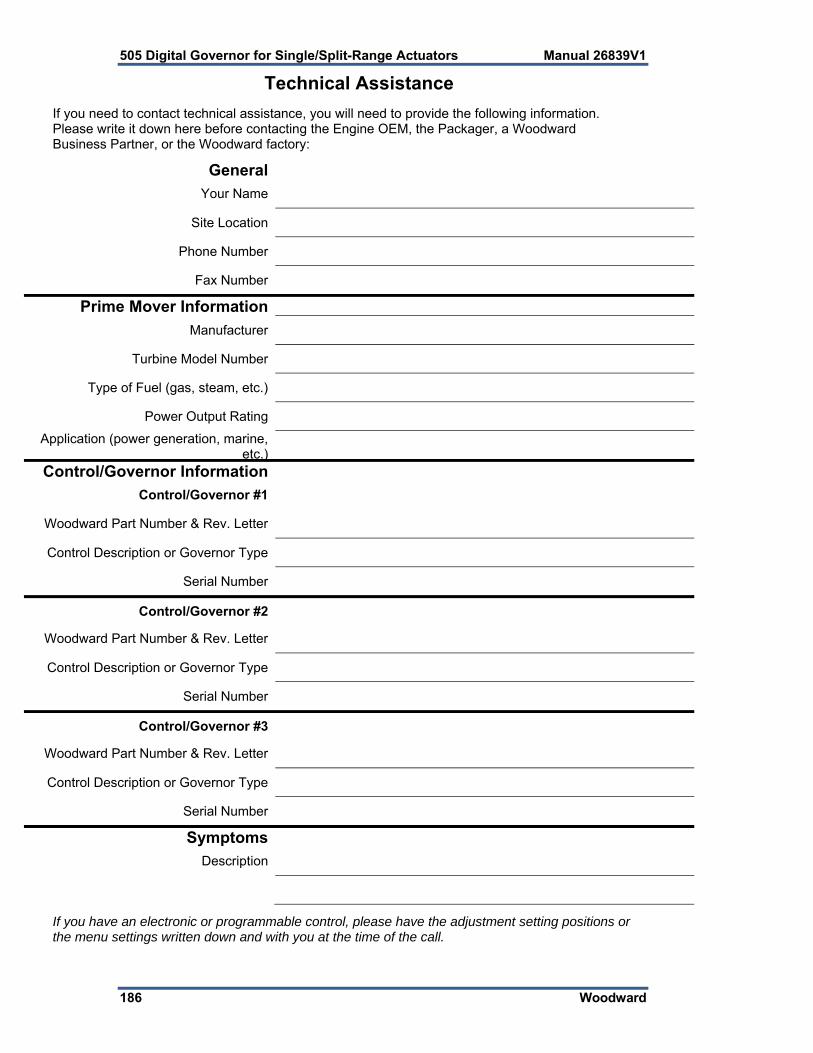
505 Digital Governor for Single/Split-Range Actuators Manual 26839V1
186 Woodward
Technical Assistance
If you need to contact technical assistance, you will need to provide the following information. Please write it down here before contacting the Engine OEM, the Packager, a Woodward Business Partner, or the Woodward factory:
General
Your Name
Site Location
Phone Number
Fax Number
Prime Mover Information
Manufacturer
Turbine Model Number
Type of Fuel (gas, steam, etc.)
Power Output Rating
Application (power generation, marine, etc.)
Control/Governor Information
Control/Governor #1
Woodward Part Number & Rev. Letter
Control Description or Governor Type
Serial Number
Control/Governor #2
Woodward Part Number & Rev. Letter
Control Description or Governor Type
Serial Number
Control/Governor #3
Woodward Part Number & Rev. Letter
Control Description or Governor Type
Serial Number
Symptoms
Description
If you have an electronic or programmable control, please have the adjustment setting positions or the menu settings written down and with you at the time of the call.

Manual 26839V1 505 Digital Governor for Single/Split-Range Actuators
Woodward 187
Appendix A. 505 Program Mode Worksheets
Governor Serial Number ______________________ Application ________________________________ Date ___________ For details on individual settings, refer to Chapter 4. TURBINE START
Start Mode
Manual Start YES NO
Automatic Start YES NO
Semiautomatic Start YES NO
Rate to Min (rpm/s) RPM/s
Valve Limiter Rate (%/s) %/s
Start Sequence
No Start Sequence YES NO
Idle/Rated Sequence YES NO
Auto Start Sequence YES NO
Use Temperature for Hot/Cold YES NO
Hot Reset Level (rpm) RPM
Hot Reset Timer (min) MIN
Cold Start = (hr since trip > xx Hrs) HRS
Hot Start = (hr since trip < xx Hrs) HRS
Use Temperature Input 2 YES NO
Hot Minimum Temperature 1 Units
Hot Minimum Temperature 2 Units
Use Warm Condition YES NO
Warm Minimum Temperature 1 Units
Warm Minimum Temperature 2 Units
Use Temperature Difference YES NO
Hot Temperature Difference Units
Warm Temperature Difference Units
Idle/Rated Settings
Idle Setpoint (rpm) RPM
Rated Setpoint (rpm) RPM
Cold Rate (rpm/s) RPM/s
Warm Rate (rpm/s) RPM/s
Hot Rate (rpm/s) RPM/s
Automatic Start Sequence Settings
Idle 1 Setpoint (rpm) RPM
Cold Idle 1 Delay MIN

505 Digital Governor for Single/Split-Range Actuators Manual 26839V1
188 Woodward
Warm Idle 1 Delay MIN
Hot Idle 1 Delay MIN
Use Idle 2 YES NO
Cold Rate to Idle 2 RPM/s
Warm Rate to Idle 2 RPM/s
Hot Rate to Idle 2 RPM/s
Idle 2 Setpt (rpm) RPM
Cold Idle 2 Delay MIN
Warm Idle 2 Delay MIN
Hot Idle 2 Delay MIN
Use Idle 3 YES NO
Cold Rate to Idle 3 RPM/s
Warm Rate to Idle 3 RPM/s
Hot Rate to Idle 3 RPM/s
Idle 3 Setpoint RPM
Cold Idle 3 Delay MIN
Warm Idle 3 Delay MIN
Hot Idle 3 Delay MIN
Use Temperature for Idle YES NO
Use Temperature Input 2 YES NO
Use Temperature Difference YES NO
Temperature 1 Setpoint for Idle 1 Units
Temperature 2 Setpoint for Idle 1 Units
Maximum Temperature Difference for Idle 1 Units
Temperature 1 Setpoint for Idle 2 Units
Temperature 2 Setpoint for Idle 2 Units
Maximum Temperature Difference for Idle 2 Units
Temperature 1 Setpoint for Idle 3 Units
Temperature 2 Setpoint for Idle 3 Units
Maximum Temperature Difference for Idle 3 Units
Cold Rate to Rated RPM/s
Warm Rate to Rated RPM/s
Hot Rate to Rated RPM/s
Rated Setpoint RPM
Auto Halt at Idle Setpoints YES NO
SPEED SETPOINTS
Overspeed Test Limit (rpm) RPM
Overspeed Trip (rpm) RPM
Max Governor Speed (rpm) RPM
Rated Speed (rpm) RPM
Min Governor Speed (rpm) RPM
Off-line Slow Rate (rpm/s) RPM/s

Manual 26839V1 505 Digital Governor for Single/Split-Range Actuators
Woodward 189
On-line Slow Rate (rpm/s) RPM/s
Remote Setpoint Speed kW
Remote Speed or kW Setpoint Maximum Rate Units/s
Use Critical Speeds? YES NO
Critical Speed Rate RPM/s
Critical Speed 1 Min RPM
Critical Speed 1 Max RPM
Use Critical Band 2 ? YES NO
Critical Speed 2 Min RPM
Critical Speed 2 Max RPM
Use Critical Band 3 ? YES NO
Critical Speed 3 Min RPM
Critical Speed 3 Max RPM
SPEED CONTROL
Select Probe Type MPU Active
Device Tag
Number of Gear Teeth Teeth
Gear Ratio 1
Maximum Speed Level (rpm) RPM
Failed Speed Level (rpm) RPM
Use Speed Input Channel 2 YES NO
Select Probe Type MPU Active
Device Tag
Number of Gear Teeth Teeth
Gear Ratio 2
Maximum Speed Level (rpm) RPM
Failed Speed Level (rpm) PRM
Off-Line Proportional Gain % %
Off-Line Integral Gain rps rps
Off-Line Derivative Ratio % %
On-Line Proportional Gain % %
On-Line Integral Gain rps rps
On-Line Derivative Ratio % %
OPERATING PARAMETERS
Generator Application? YES NO
Generator Settings
Use Generator Breaker Open Trip ? YES NO
Use Tie Breaker Open Trip ? YES NO
Frequency at Rated (50/60 Hz) Hz
Droop (%) %

505 Digital Governor for Single/Split-Range Actuators Manual 26839V1
190 Woodward
Use Load Droop? YES NO
Use MW as Load Units? YES NO
Max Load kW
Primary Generator Load Signal
Secondary Generator Load Signal
Primary Sync/Load Share Signal
Secondary Sync/Load Share Signal
Primary Sync Signal
Secondary Sync Signal
Use Frequency Arm/Disarm? YES NO
Reverse Power on Controlled Stop? YES NO
Mechanical Drive Settings
Use Feed-Forward YES NO
Feed Forward Speed Deadband
Use Only when Cascade YES NO
Cascade Deadband when Forward Active
Use Direct Feed-Forward YES NO
Speed Offset at 4 mA RPM
Speed Offset at 20 mA RPM
Action Delay s
Min Forward Rate %/s
Speed offset at Min Rate RPM
Max Forward Rate %/s
Speed offset at Max Rate RPM
Use Emergency YES NO
Emergency Action Delay s
Forward Rate to Activate %/s
Emrg Max Forward Rate %/s
Emrg Max Speed Offset RPM
Emrg Max Speed Rate RPM/s
Controlled Stop & Trip YES NO
External Trips in Trip Relay YES NO
Reset Clears Trip Output YES NO
Use Local/Remote YES NO
Use Pressure Compensation YES NO
AUXILIARY CONTROL
Use Auxiliary Control ? YES NO
Lost Input Shutdown? YES NO
Process Signal
Inverted? YES NO
Minimum Setpoint Units
Maximum Setpoint Units

Manual 26839V1 505 Digital Governor for Single/Split-Range Actuators
Woodward 191
Setpoint Rate Units/s
Use as Controller? YES NO
Setpoint Initial Value Units
Droop % %
PID Proportional Gain % %
PID Integral Gain rps rps
PID Derivative Ratio % %
Tie Breaker Open Aux Disable YES NO
Gen Breaker Open Aux Disable YES NO
Use Remote Setpoint YES NO
Remote Max Rate Units/s
Units of Measure Configured with AI
Decimals Displayed Configured with AI
AUXILIARY 2 CONTROL
Use Auxiliary Control ? YES NO
Lost Input Shutdown? YES NO
Process Signal
Inverted? YES NO
Minimum Setpoint Units
Maximum Setpoint Units
Setpoint Rate Units/s
Use as Controller? NO
Setpoint Initial Value Units
PID Proportional Gain % %
PID Integral Gain rps rps
PID Derivative Ratio % %
Use Remote Setpoint YES NO
Remote Max Rate Units/s
Units of Measure Configured with AI
Decimals Displayed Configured with AI
CASCADE CONTROL
Use Cascade Control? YES NO
Process Signal
Inverted? YES NO
Minimum Cascade Setpoint Units
Maximum Cascade Setpoint Units
Cascade Setpoint Rate (Units/s) Units/s
Use Setpoint Tracking? YES NO
Setpoint Initial Value Units
Speed Setpoint Lower Limit RPM

505 Digital Governor for Single/Split-Range Actuators Manual 26839V1
192 Woodward
Speed Setpoint Upper Limit RPM
Max Speed Setpoint Rate (rpm/s) RPM/s
Cascade Droop % %
PID Proportional Gain % %
PID Integral Gain rps rps
PID Derivative Ratio % %
Use Remote Cascade Setpoint YES NO
Remote Cascade Max Rate Units/s
Units of Measure Configured with AI
Decimals Displayed Configured with AI
ISOLATED CONTROL
Use Isolated PID YES NO
Use Remote Setpoint YES NO
Output Action on Input Fault
Invert Controller? YES NO
Allow Manual Control? YES NO
COMMUNICATIONS
Ethernet IP Configuration
ENET 1 Address
ENET 1 Subnet Mask
ENET 2 Address
ENET 2 Subnet Mask
ENET 3 Address
ENET 3 Subnet Mask
ENET 4 Address
ENET 4 Subnet Mask
Modbus Configuration
Use Modbus YES NO
Use Serial Link 1 YES NO
Use Ethernet Link 2 YES NO
Use Ethernet Link 3 YES NO
Device Address (1-247)
Enable Write Commands YES NO
Protocol ASCII RTU
Baud Rate
Bits 7 8
Stop Bits 1 2
Parity
Driver
Modbus Ethernet Link 2

Manual 26839V1 505 Digital Governor for Single/Split-Range Actuators
Woodward 193
Ethernet Protocol TCP UDP 5001
Device Address (1-247)
Enable Write Commands YES NO
Modbus Ethernet Link 3
Ethernet Protocol TCP UDP 5002
Device Address (1-247)
Enable Write Commands YES NO
ANALOG INPUTS
Analog Input 01
Input Function
4 mA Value Units
20 mA Value Units
Loop Powered YES NO
Device Tag
Units
Modbus Multiplier
Decimals Displayed
Analog Input 02
Input Function
4 mA Value Units
20 mA Value Units
Loop Powered YES NO
Device Tag
Units
Modbus Multiplier
Decimals Displayed
Analog Input 03
Input Function
4 mA Value Units
20 mA Value Units
Loop Powered YES NO
Device Tag
Units
Modbus Multiplier
Decimals Displayed
Analog Input 04
Input Function
4 mA Value Units
20 mA Value Units
Loop Powered YES NO
Device Tag
Units

505 Digital Governor for Single/Split-Range Actuators Manual 26839V1
194 Woodward
Modbus Multiplier
Decimals Displayed
Analog Input 05
Input Function
4 mA Value Units
20 mA Value Units
Loop Powered YES NO
Device Tag
Units
Modbus Multiplier
Decimals Displayed
Analog Input 06
Input Function
4 mA Value Units
20 mA Value Units
Loop Powered YES NO
Device Tag
Units
Modbus Multiplier
Decimals Displayed
Analog Input 07
Input Function
4 mA Value Units
20 mA Value Units
Loop Powered YES NO
Device Tag
Units
Modbus Multiplier
Decimals Displayed
Analog Input 08
Input Function
4 mA Value Units
20 mA Value Units
Loop Powered YES NO
Device Tag
Units
Modbus Multiplier
Decimals Displayed
ANALOG OUTPUTS
Analog Output 01
Output Function
4 mA Value Units

Manual 26839V1 505 Digital Governor for Single/Split-Range Actuators
Woodward 195
20 mA Value Units
Device Tag
Units
Enable Readback Fault YES NO
Analog Output 02
Output Function
4 mA Value Units
20 mA Value Units
Device Tag
Units
Enable Readback Fault YES NO
Analog Output 03
Output Function
4 mA Value Units
20 mA Value Units
Device Tag
Units
Enable Readback Fault YES NO
Analog Output 04
Output Function
4 mA Value Units
20 mA Value Units
Device Tag
Units
Enable Readback Fault YES NO
Analog Output 05
Output Function
4 mA Value Units
20 mA Value Units
Device Tag
Units
Enable Readback Fault YES NO
Analog Output 06
Output Function
4 mA Value Units
20 mA Value Units
Device Tag
Units
Enable Readback Fault YES NO
DRIVERS
Actuator 01
Function

505 Digital Governor for Single/Split-Range Actuators Manual 26839V1
196 Woodward
Range 4-20 mA 0-200 mA
Dither %
Use Actuator Fault Shutdown YES NO
Invert Output YES NO
Device Tag
HP2 Offset %
Readout Function
4 mA Value Units
20 mA Value Units
Enable Readback Fault YES NO
Device Tag
Units
Actuator 02
Function
Range 4-20 mA 0-200 mA
Dither %
Use Actuator Fault Shutdown YES NO
Invert Output YES NO
Device Tag
HP2 Offset %
Readout Function
4 mA Value Units
20 mA Value Units
Enable Readback Fault YES NO
Device Tag
Units
CONTACT INPUTS
Contact Input 01
Input Function Emergency Stop
Device Tag
Contact Input 02
Input Function
Device Tag
Invert Logic? YES NO
Contact Input 03
Input Function
Device Tag
Invert Logic? YES NO
Contact Input 04
Input Function
Device Tag
Invert Logic? YES NO

Manual 26839V1 505 Digital Governor for Single/Split-Range Actuators
Woodward 197
Contact Input 05
Input Function
Device Tag
Invert Logic? YES NO
Contact Input 06
Input Function
Device Tag
Invert Logic? YES NO
Contact Input 07
Input Function
Device Tag
Invert Logic? YES NO
Contact Input 08
Input Function
Device Tag
Invert Logic? YES NO
Contact Input 09
Input Function
Device Tag
Invert Logic? YES NO
Contact Input 10
Input Function
Device Tag
Invert Logic? YES NO
Contact Input 11
Input Function
Device Tag
Invert Logic? YES NO
Contact Input 12
Input Function
Device Tag
Invert Logic? YES NO
Contact Input 13
Input Function
Device Tag
Invert Logic? YES NO
Contact Input 14
Input Function
Device Tag
Invert Logic? YES NO
Contact Input 15
Input Function
Device Tag
Invert Logic? YES NO

505 Digital Governor for Single/Split-Range Actuators Manual 26839V1
198 Woodward
Contact Input 16
Input Function
Device Tag
Invert Logic? YES NO
Contact Input 17
Input Function
Device Tag
Invert Logic? YES NO
Contact Input 18
Input Function
Device Tag
Invert Logic? YES NO
Contact Input 19
Input Function
Device Tag
Invert Logic? YES NO
Contact Input 20
Input Function
Device Tag
Invert Logic? YES NO
RELAYS
Relay Output 01
Function
Device Tag
Relay Output 02
Use as Level Switch? YES NO
Function
Device Tag
Invert Output YES NO
ON Level Units
OFF Level Units
Relay Output 03
Use as Level Switch? YES NO
Function
Device Tag
Invert Output YES NO
ON Level Units
OFF Level Units
Relay Output 04
Use as Level Switch? YES NO
Function
Device Tag

Manual 26839V1 505 Digital Governor for Single/Split-Range Actuators
Woodward 199
Invert Output YES NO
ON Level Units
OFF Level Units
Relay Output 05
Use as Level Switch? YES NO
Function
Device Tag
Invert Output YES NO
ON Level Units
OFF Level Units
Relay Output 06
Use as Level Switch? YES NO
Function
Device Tag
Invert Output YES NO
ON Level Units
OFF Level Units
Relay Output 07
Use as Level Switch? YES NO
Function
Device Tag
Invert Output YES NO
ON Level Units
OFF Level Units
Relay Output 08
Use as Level Switch? YES NO
Function
Device Tag
Invert Output YES NO
ON Level Units
OFF Level Units
WOODWARD LINKS
DSLC-2
Using a DSLC-2? YES NO
Use Synchronization/Load Share? Sync Sync/LS
Device Slave Address (1-255)
Device IP Address
505 Ethernet 3 IP Address
VS-II
Enable CAN 1 Interface Link? YES NO
Using a VariStroke II Actuator? YES NO
DVP1 Device ID (1-31)

505 Digital Governor for Single/Split-Range Actuators Manual 26839V1
200 Woodward
Enable DVP1 AI Backup? YES NO
Use AI as Primary Demand? YES NO
Select Function HP Demand Split HP2
Using 2 VariStroke II Actuators? YES NO
When Actuator Outputs have been (In Service) Calibrated and Stroked, record values here.
Default 505 Unit #1 Value in 505 Actuator # 1 mA at Minimum Position *4.00 Actuator # 1 mA at Maximum Position *20.00 Actuator # 1 Dither (%) *0.00 Actuator # 2 mA at Minimum Position *4.00 Actuator # 2 mA at Maximum Position *20.00 Actuator # 2 Dither (%) *0.00

Manual 26839V1 505 Digital Governor for Single/Split-Range Actuators
Woodward 201
Appendix B. 505 Marine XXXX-XXXX
For future release

505 Digital Governor for Single/Split-Range Actuators Manual 26839V1
202 Woodward
Declarations
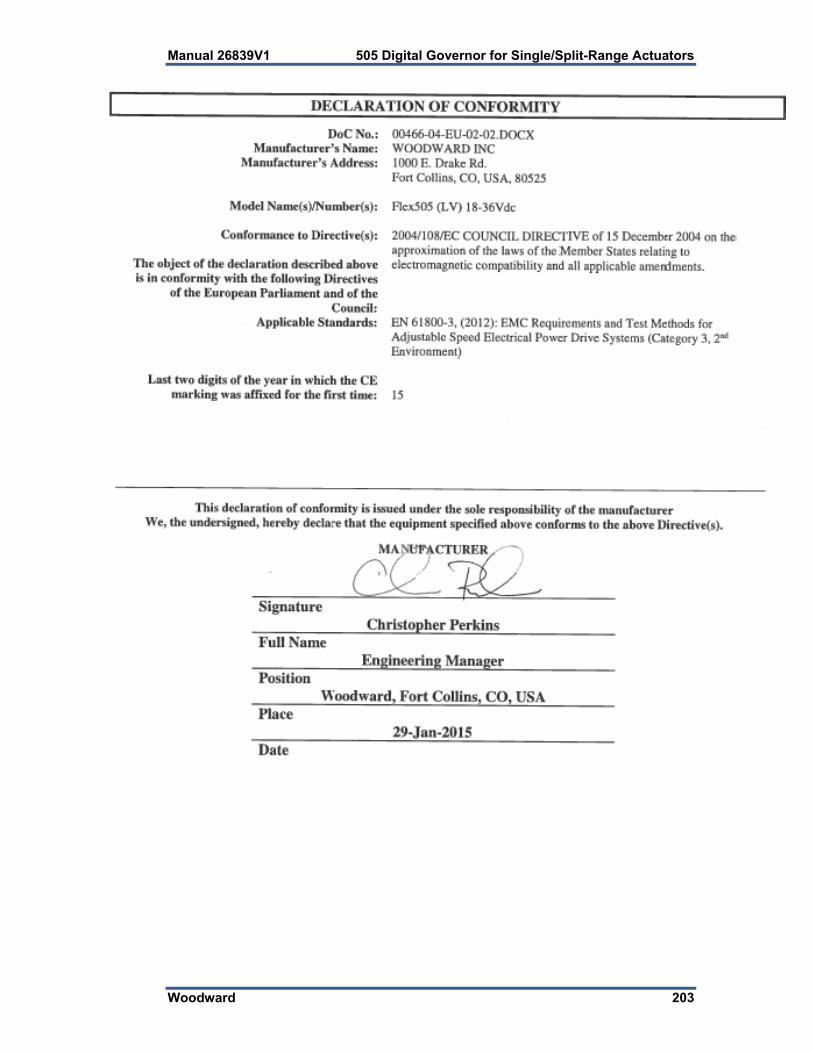
Manual 26839V1 505 Digital Governor for Single/Split-Range Actuators
Woodward 203

We appreciate your comments about the content of our publications.
Send comments to: [email protected]
Please reference publication 26839V1.
PO Box 1519, Fort Collins CO 80522-1519, USA 1000 East Drake Road, Fort Collins CO 80525, USA Phone +1 (970) 482-5811 Fax +1 (970) 498-3058
Email and Website—www.woodward.com
Woodward has company-owned plants, subsidiaries, and branches, as well as authorized distributors and other authorized service and sales facilities throughout the world.
Complete address / phone / fax / email information for all locations is available on our website.