‘55-chevy truck 4-link ‘59 - classic performance products truck_c… · ‘55-chevy truck...
TRANSCRIPT
Page 1 of 10 (c) 2010 Total Cost Involved Engineering, Inc. All Rights Reserved.
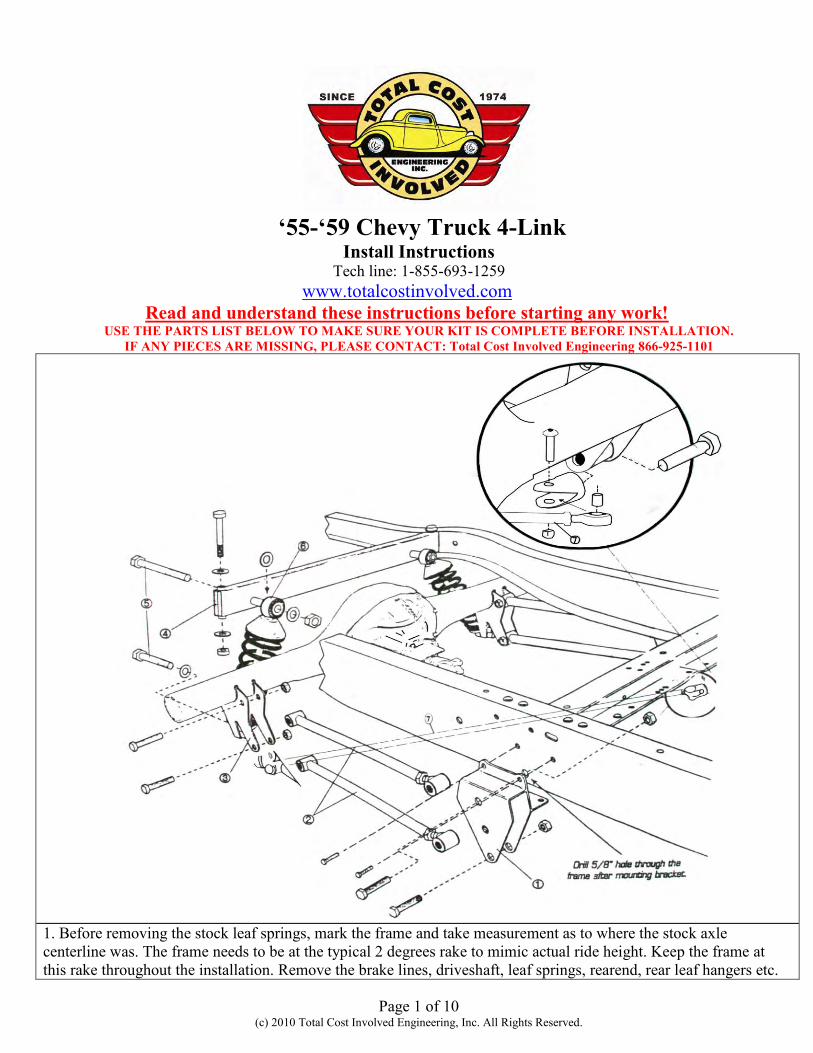
‘55-‘59 Chevy Truck 4-Link
Install Instructions Tech line: 1-855-693-1259
www.totalcostinvolved.com Read and understand these instructions before starting any work!
USE THE PARTS LIST BELOW TO MAKE SURE YOUR KIT IS COMPLETE BEFORE INSTALLATION. IF ANY PIECES ARE MISSING, PLEASE CONTACT: Total Cost Involved Engineering 866-925-1101
1. Before removing the stock leaf springs, mark the frame and take measurement as to where the stock axle centerline was. The frame needs to be at the typical 2 degrees rake to mimic actual ride height. Keep the frame at this rake throughout the installation. Remove the brake lines, driveshaft, leaf springs, rearend, rear leaf hangers etc.

Page 2 of 10 (c) 2010 Total Cost Involved Engineering, Inc. All Rights Reserved.
This picture was taken with the frame flipped upside down to get a better shot. The two rivets holding the stock cross member must be removed in order to install the 4-link frame brackets. Use a grinder to remove the rivet heads.
Once the rivet heads have been trimmed back to the top of the frame rail use a punch and a hammer to knock out the rivets.
Drill through the holes with a 7/16” bit.

Page 3 of 10 (c) 2010 Total Cost Involved Engineering, Inc. All Rights Reserved.
The new bracket will be using the holes that were just drilled out on the bottom and two more per side shown in the picture to the left. Drill out all rivet holes to 7/16”. There are two on the side of the frame and two underneath (on both passenger & driver sides).
Determining left and right side brackets: The lower 4-link bar hole on the frame brackets will be further forward than the upper holes and the brackets sit on the outside of the frame rail. Place the 4-link frame brackets onto the frame where the original front spring perch used to be. Make sure the existing holes line up and install the 7/16” hardware with the nuts on the inside of the frame. Torque to 55 ft lbs Torque these 4 bolts to 55 ft lbs
Locate the 5/8” upper 4-link bar hole within the new bracket. Using a 5/8” bit, drill through the frame using the existing 5/8” hole on the bracket as a guide. This will be for the attachment point for the upper link bar.

Page 4 of 10 (c) 2010 Total Cost Involved Engineering, Inc. All Rights Reserved.
Here is a shot from inside the frame after the 5/8” hole has been drilled.
Welding the Axle brackets onto the housing:
The factory leaf spring pads must first be removed from the housing and the area cleaned up. The axle brackets are installed at 36” Center to center. Make sure that they are centered on the housing. Also, make sure the pinion is pointed up one degree in comparison to the flat area at the backside of the brackets (where the three holes for the coil-overs are located). Use the 3rd member mounting face on a Ford 9” or the differential cover on a GM housing as reference.
Adjust all the 4-link bars to 24.25” center to center and tighten the jam nuts. *NOTE* It might be necessary to adjust the 4-link bars later to center the tires in the wheel wells.

Page 5 of 10 (c) 2010 Total Cost Involved Engineering, Inc. All Rights Reserved.
Install the 4-link bars with the adjuster side onto the frame using the provided 5/8” hardware. The bolts go in from the outside of the frame which will place the nylock on the inboard side. *NOTE* The driver’s side front lower link bar does not use a nylock nut, rather a clevis for attaching the track bar. Install the clevis onto this bolt at this time. Torque all 5/8” hardware to 125 ft lbs(the clevis can be left hand tight for now)
Place the lower 4-link bars onto the lower hole of the axle bracket using the provided 5/8” hardware. *NOTE* The passenger side rear lower link bar does not use a nylock nut, rather a clevis for attaching the track bar. Install the clevis onto this bolt at this time. Leave bolts & the clevis hand tight for now
Place the upper 4-link bars onto the upper hole of the axle bracket using the provided 5/8” hardware. *NOTE* If you purchased the optional anti-sway please use the provided shoulder bolt within the anti-sway bar bolt kit. *Pictures of the anti-sway bar installation are later in this manual Leave bolts loose for now

Page 6 of 10 (c) 2010 Total Cost Involved Engineering, Inc. All Rights Reserved.
Install the offset axle brackets onto the axle brackets using the provided 5/8” hardware. These are designed to keep the coil-overs from making contact with the frame rail as the suspension compresses. The flat area of the plate will sit parallel to the ground and the shock hole will sit inboard of the bracket when properly installed. *NOTE* You may need to run a 5/8” bit through the holes Torque to 125 ft lbs
Remove the factory shock cross member using the same process as before with the leaf spring brackets.
Place the new coil-over cross member into the frame rail with the extended tube for the shock mount pointing forward. *NOTE* The new cross member will be positioned into the same holes that the factory cross member used.

Page 7 of 10 (c) 2010 Total Cost Involved Engineering, Inc. All Rights Reserved.
Drill out the factory holes with a 1/2” bit. Place the cross member into place and install the 1/2” hardware. You can now install the coil-overs using the provided 5/8” hardware. The threaded side goes down as per the picture. *NOTE* The springs were left off the shock for this picture to show the threaded end more clearly. Your shocks will come preassembled. Torque the 1/2” cross member bolts to 65 ft lbs Torque the 5/8” shock bolts to 125 ft lbs
Install one rod end of the track bar onto either clevis and use it as leverage to tighten it down. Remove the rod end from that clevis and repeat this process on the other clevis. You may need to rotate the clevis so that the 9/16” bolts holding the rod end are sitting vertical. Install the track bar completely onto the clevises. Make sure the rear end is centered in the frame and that the wheel base is correct by adjusting the Link & Track bars accordingly. Tighten down the jam nuts on the Track and 4-link bars. Torque the 9/16” bolts to 75 ft lbs
If you purchased the optional anti-sway bar proceed to the next step.
If not, reinstall the driveshaft, brake lines etc and drop the vehicle down onto its full weight. Adjust ride height as needed with the coil-over shocks. Double check all hardware and make sure the pinion angle is still one degree up. Adjust the link bars accordingly.
Installing the optional Anti-Sway bar:

Page 8 of 10 (c) 2010 Total Cost Involved Engineering, Inc. All Rights Reserved.
LOCATING THE REAR ANTI-ROLL BAR HOUSING TO THE FRAME: *NOTE* The pictured frame has been boxed Mark the frame 2 1/4” from the rear face of the coilover cross member.
Measure down 2 1/8” down from the top of the rail at the mark you just made. Use a center punch to mark the frame where these two measurements intersect. This is the anti-roll bar housing centerline. Duplicate the last two steps for the opposite side of the vehicle. Use a 1 ¼” hole saw to drill through the frame at the marked location.
Place the housing through the frame making sure it protrudes the same distance on both sides. Once it is centered, it can be welded into place.
Page 9 of 10 (c) 2010 Total Cost Involved Engineering, Inc. All Rights Reserved.
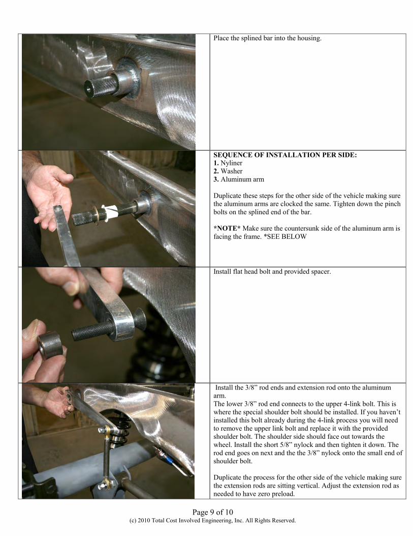
Place the splined bar into the housing.
SEQUENCE OF INSTALLATION PER SIDE: 1. Nyliner 2. Washer 3. Aluminum arm Duplicate these steps for the other side of the vehicle making sure the aluminum arms are clocked the same. Tighten down the pinch bolts on the splined end of the bar. *NOTE* Make sure the countersunk side of the aluminum arm is facing the frame. *SEE BELOW
Install flat head bolt and provided spacer.
Install the 3/8” rod ends and extension rod onto the aluminum arm. The lower 3/8” rod end connects to the upper 4-link bolt. This is where the special shoulder bolt should be installed. If you haven’t installed this bolt already during the 4-link process you will need to remove the upper link bolt and replace it with the provided shoulder bolt. The shoulder side should face out towards the wheel. Install the short 5/8” nylock and then tighten it down. The rod end goes on next and the the 3/8” nylock onto the small end of shoulder bolt. Duplicate the process for the other side of the vehicle making sure the extension rods are sitting vertical. Adjust the extension rod as needed to have zero preload.

Page 10 of 10 (c) 2010 Total Cost Involved Engineering, Inc. All Rights Reserved.
Here is how the finalized installation will look.
No returns or exchanges without a RMA#.
Packages must be inspected upon receipt & be reported within 10 days. If you are missing parts from your kit, TCI Engineering will send the missing parts via FedEx or U.S. mail ground.
Returned packages are subject to inspection before replacement/refund is given.(Some items will be subject to a 15% restocking fee)
Thank you for your business!