6-36kv medium voltage underground power cables · 2017-10-12 · medium voltage underground cables...
TRANSCRIPT

6-36kV Medium Voltage Underground Power Cables
XLPE insulated cables

Med ium Vo l tage Underground Cab les
2
Cable solutions to ensure the reliability of your energy
network
With energy as the basis of its development, Nexans, the worldwide leader
in the cable industry, offers an extensive range of cables and cabling systems.
The Group is a global player in the infrastructure, industry, building and Local

Med ium Vo l tage Underground Cab les
3
Area Network markets. Nexans addresses a series of market segments from
energy, transport and telecom networks to shipbuilding, oil and gas, nuclear
power, automotive, electronics, aeronautics, handling and automation.

Med ium Vo l tage Underground Cab les
4
CABLE
l Cable power circuit design 7
n Conductor 7-8
n Conductor screen 8
n Insulation 8
n Insulation screen 8-9
n Metallic screen 9-10
n Outer protective sheath 10-11
l Table of cable elements 12
l Cable constructions 13
l Cable drums 14
l Cable tests following production 15
ACCESSORIES
l Introduction 16
l Connectors and lugs 16
l Electrical fields 17
l Terminations 17
n Leakage path and creepage distance 17-18
n Slip-on termination 18
n Heat-shrinkable termination 18
n Cold-shrinkable termination 18
l Screened, separable connectors 18-19
l Surge arresters 19
l Joints 19
n Transition joints 19
I
II
Contents
page
Med ium Vo l tage Underground Cab les
5
INSTALLATION
l Cable Drum Handling 20
l Installation Environment 20
l Type of installation 21
l Installation Temperature 22
l Pulling Forces 23
l Bending Radii 23
l Cable Support Spacing 23
l Special Civil Engineering Works 24
l Tests after installation 24
l Current ratings 25
TECHNICAL SPECIFICATIONS
l Introduction 26
l 3.8/6.6 (7.2) kV Three Core armoured copper conductors 27
l 6.35/11 (12) kV Triplex / Single Core unarmoured copper conductors 28
l 6.35/11 (12) kV Triplex / Single Core unarmoured aluminium conductors 29
l 6.35/11 (12) kV Three Core unarmoured copper conductors 30
l 6.35/11 (12) kV Three Core unarmoured aluminium conductors 31
l 6.35/11 (12) kV Single Core armoured copper conductors 32
l 6.35/11 (12) kV Single Core armoured aluminium conductors 33
l 6.35/11 (12) kV Three Core armoured copper conductors 34
l 6.35/11 (12) kV Three Core armoured aluminium conductors 35
l 8.7/15 (17.5) kV Single Core armoured copper conductors 36
l 8.7/15 (17.5) kV Three Core armoured copper conductors 37
l 12/20 (22) kV Single Core copper unarmoured conductors 38
l 12/20 (22) kV Single Core armoured copper conductors 39
l 12/20 (22) kV Three Core armoured copper conductors 40
l 19/33 (36) kV Single Core unarmoured copper conductors 41
l 19/33 (36) kV Single Core unarmoured aluminium conductors 42
l 19/33 (36) kV Single Core armoured copper conductors 43
l 19/33 (36) kV Three Core armoured copper conductors 44
page
III
IV
All the data given in this brochure is com-municated for information only and is not
legally binding to Nexans
Med ium Vo l tage Underground Cab les
6
General power circuit design
This brochure
deals with underground power
circuits featuring three-phase AC
voltage insulated cable with a rated
voltage between 6.6kV and 36kV. These
lines are mainly used in a distribution
network for electrical power, connecting
local substations or small generating units
such as wind turbines to the main grid
supply point, or for connecting plant in
industrial processes which require large
amounts of power. Medium voltage
insulated cables may also be used in
conjunction with bare overhead
lines in networks.
The voltage of a circuit is designated
in accordance with the following
principles:
Example:
Uo/U (Um) : 19/33 (36)
Phase-to-ground voltage,
designated Uo is the effective value
of the voltage between the conductor
and the ground or metallic screen
Rated voltage, designated U, is
the effective phase to phase voltage.
Maximum voltage, designated U,
is the permissible highest voltage for
which the equipment is specified.
In addition, the basic impulse
level (BIL) determines the maximum
capacity any equipment will withstand
if subjected to a lightning strike.
The rated voltage of a medium
voltage cable is determined by the
thickness of the insulation. Unlike
high voltage cables which do not
have set values for the insulation
thickness, the thickness of the
insulation around a conductor
in a medium voltage cable is set
at specified levels according to
international standards.
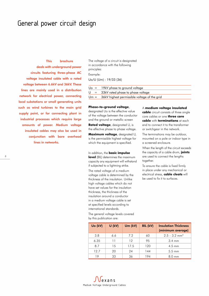
The general voltage levels covered
by this publication are:
A medium voltage insulated
cable circuit consists of three single
core cables or one three core
cable with terminations at each
end to connect it to the transformer
or switchgear in the network.
The terminations may be outdoor,
mounted on a pole or indoor type in
a screened enclosure.
When the length of the circuit exceeds
the capacity of a cable drum, joints
are used to connect the lengths
together.
To ensure the cable is fixed firmly
in place under any mechanical or
electrical stress, cable cleats will
be used to fix it to surfaces.
Uo = 19kV phase to ground voltage
U = 33kV rated phase to phase voltage
Um = 36kV highest permissible voltage of the grid
Uo (kV) U (kV) Um (kV) BIL (kV) Insulation Thickness
(minimum average)
3.8 6.6 7.2 60 2.5 – 3.2 mm*
6.35 11 12 95 3.4 mm
8.7 15 17.5 120 4.5 mm
12.7 20 24 144 5.5 mm
19 33 36 194 8.0 mm

Med ium Vo l tage Underground Cab les
7
The cable
The structure of medium voltage
cables with extruded insulation will
always involve the following items:
CONDUCTOR CORE
For medium voltage cables,
conductors are rated by their
effective cross sectional area in mm2
– this indicates how much current
can flow through the conductor –
i.e. the larger the conductor, the
greater the amount of current.
Conductors for medium voltage are
normally used in the range from
35mm2 up to 1000mm2 and are
usually either compacted stranded
or solid construction.
In some three core designs, sector
shaped conductors can be used to
reduce the overall diameter of the
cable.
As copper has a lower electrical
resistance than aluminium, it is a
more efficient conductor of electrical
current and requires smaller cross
sections to carry the same amount of
power as an aluminium conductor.
For example, a copper conductor
of 300mm2 cross section can carry
approx 670 Amps in a buried
installation, yet an aluminium
conductor will carry only approx 525
Amps under the same conditions. It
would require a larger cross section
of 500mm2 to achieve the same
rating.
However, aluminium is substantially
lighter than copper and therefore
has the advantage of enabling
longer lengths to be safely handled,
meaning less jointing. Also,
aluminium is generally lower in
price than copper on the metals
commodity markets making it more
economical per amp than copper.
Therefore, aluminium conductors
are usually used for medium voltage
distribution networks requiring long
distances and extensive cabling,
whereas copper cables are used
for short links in substations and
industrial installations where smaller
cables or higher power transmitting
properties are required.
Stranded conductors consist of
several layers of spiral wound wires
which are compacted together.
They are normally constructed as
Class 2 according to IEC 60228
(BS EN 60228), although it is
possible to use Class 5 flexible
stranded conductors in conjunction
with Ethylene Propylene Rubber (EPR)
insulation for short leads.
As stranded conductors will have
spaces in the interces, there may
be a requirement to longitudinally
water-block the conductor by using
water swellable powders or tapes in
the conductor construction. These
materials will block the travel of any
moisture through the conductor if
it was to enter at a termination or
joint position. Aluminium conductors
are usually water-blocked to prevent
the corrosive reaction with water,
but copper cables are normally not
specified with these materials unless
the cable is to be used in very wet
conditions, e.g. subsea cables.
Aluminium solid conductors, by
their design are water-blocked
and usually are of slightly reduced
diameter than the equivalent
stranded versions. However, it is
usually too difficult to handle these
conductors for terminating and
jointing for cross sections above
300mm2.
Compact round conductors,
composed of several layers of
concentric spiral-wound wires.
Med ium Vo l tage Underground Cab les
8
Around the conductor, it is necessary
to provide insulation to prevent
electrical short circuits. In medium
voltage cables there are two main
types of insulation material:
l XLPE – Cross linked Polyethylene –
the most common material for MV
cables today.
l EPR – Ethylene Propene Rubber
– more flexible than XLPE but not
as efficient at reducing losses in
circuits as XLPE. Cables used in
marine and offshore applications
are normally constructed with EPR
insulation.
Note:
As the most common type of
insulation, all data provided in this
handbook is based on cables with
XLPE insulation.
According to the requirements
of various standards, cables for
medium and high voltages require
three specific layers of extruded
material around the conductor to
form the insulation system.
These layers are known as the
conductor screen, insulation and
insulation screen and are normally
extruded in one operation, known as
triple pass, or triple extruded.
SEMI-CONDUCTOR
SCREEN ON THE
CONDUCTOR (KNOWN
AS THE “CONDUCTOR
SCREEN”)
This consists of a layer of black
semi-conductive cross–linked
compound, usually less than 1.0mm
in thickness, which is the interface
between the conductor and the
insulation.
The external surfaces of the
conductor may not be smooth,
particularly for stranded conductors,
so this layer provides a smooth
surface at the same potential as
the conductor to keep the electric
field consistent all the way around
the surface. Without this layer, any
small peaks or troughs could cause
concentrations of electrical energy
which could create small arcs, and
over time could erode the insulation
layer and cause failure of the cable.
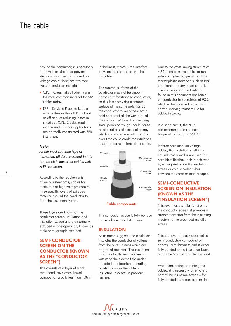
The conductor screen is fully bonded
to the adjacent insulation layer.
INSULATION
As its name suggests, the insulation
insulates the conductor at voltage
from the outer screens which are
at ground potential. The insulation
must be of sufficient thickness to
withstand the electric field under
the rated and transient operating
conditions – see the table on
insulation thickness in previous
section.
Due to the cross linking structure of
XLPE, it enables the cables to run
safely at higher temperatures than
thermoplastic materials such as PVC,
and therefore carry more current.
The continuous current ratings
found in this document are based
on conductor temperatures of 90°C
which is the accepted maximum
normal working temperature for
cables in service.
In a short circuit, the XLPE
can accommodate conductor
temperatures of up to 250°C.
In three core medium voltage
cables, the insulation is left in its
natural colour and is not used for
core identification – this is achieved
by either printing on the insulation
screen or colour coded tubes
between the cores or marker tapes.
SEMI-CONDUCTIVE
SCREEN ON INSULATION
(KNOWN AS THE
“INSULATION SCREEN”)
This layer has a similar function to
the conductor screen: it provides a
smooth transition from the insulating
medium to the grounded metallic
screen.
This is a layer of black cross linked
semi conductive compound of
approx 1mm thickness and is either
fully bonded to the insulation layer,
or can be “cold strippable” by hand.
When terminating or jointing the
cables, it is necessary to remove a
part of the insulation screen – for
fully bonded insulation screens this
Cable components
SC conductorscreen
SC insulationscreen
Conductor
Insulation
Metallicsheath
Anti-corrosion sheath
The cable

Med ium Vo l tage Underground Cab les
9
requires a special rotary stripping
tool with blades at pre-set depths to
consistently remove the black semi-
conductive layer without removing
the insulation.
Cold Strippable screens (sometimes
referred to as “easy strippable”) do
not require such tools and can be
peeled off the insulation leaving a
clean layer of insulation.
However, it can be more difficult to
make a smooth tapered transition
between screen and insulation
with the cold strippable screen
and special care has to be taken
when using knives or other tools to
achieve this.
The rotary stripping tools for bonded
screens can leave a smooth tapered
edge at the end of the screen which
reduces any electrical stress at this
transition point.
Normally, three core cables are
specified with cold strippable screens
as it is difficult to get the rotary
tools in between the adjacent cores.
Single cores, particularly at the
higher voltage levels tend to be fully
bonded.
METALLIC SCREEN
The main function of the metallic
screen is to nullify the electric field
outside of the cable – it acts as a
second electrode of the capacitor
formed by the cable. The screen
needs to connect to earth at least at
one point along the route.
The capacitive charging current
and induced circulating currents
which are generated under normal
operating conditions will be drained
away through the screen.
The screen also drains the zero-
sequence short circuit currents under
fault conditions; this function is used
to determine the required size of the
metallic screen.
The second function of the metallic
screen is to form a radial barrier to
prevent humidity from penetrating
the cable insulation system.
The extruded insulation system
should not be exposed to humidity.
When humidity and a strong
electric field are present together,
the insulation deteriorates by what
is called water-treeing, which can
eventually cause the insulation to
fail.
Note:
In the case of an overhead line,
the insulation is formed by the air
between the bare conductor and
the ground.
The cable
Copper Wire Screen with
equalizing tape
Copper Wire Screen with a copper equalizing tape
Conductor Core
XLPE insulation
Separator tape or water
swellable tape
PE Sheath
Conductor Core
XLPE insulation
Copper Wire Screen
Aluminium foil laminate
PE Sheath
Laminate foil sheath with
additional copper wires
Conductor Core
Semi- conductive
tape
XLPE insulation
Extruded Lead alloy
sheath
PE Sheath
Lead Sheath
Med ium Vo l tage Underground Cab les
10
DIFFERENT TYPES OF
METALLIC SCREEN
Concentric Copper Wire screens
(with optional equalising tape).
Advantages:
l Lightweight and cost effective
design.
l High short-circuit capacity.
l Easy to terminate.
Drawbacks:
l Low resistance of screen may
necessitate need for special screen
connections to limit the circulating
current losses.
l Does not form a complete
moisture barrier (unless water
swellable tapes are used under
and/or over the copper wires).
Aluminium foil laminate
Advantages:
l Lightweight and cost effective
design.
l Moisture proof radial barrier.
Drawbacks:
l Low short circuit capacity.
l More difficult to terminate
– requires special screen
connections.
Extruded lead alloy sheath
Advantages:
l Waterproofing guaranteed by the
manufacturing process.
l Excellent resistance to corrosion
and hydrocarbons (suitable for oil
and gas plants).
Drawbacks:
l Heavy and expensive.
l Lead is a toxic metal whose use is
being restricted in some countries.
l Limited capacity for short circuits.
Other metallic screen constructions
such as copper tape screens can
be used, also combinations of
the mentioned designs such as
lead sheath + copper wires, or
aluminium foil laminate + copper
wires can be used to increase the
short circuit rating of the cables.
ANTI-CORROSION
PROTECTIVE JACKET (OR
SHEATH)
The outer sheath has a number of
functions:
l It insulates the metallic screen
from the ground (particularly for
lines with high circulating currents)
l It protects the metal components
of the screen from humidity and
corrosion.
l It protects the cable from the
mechanical stresses encountered
during installation and service.
It can also be tailored to withstand
specific effects such as termite
attack, resistance to hydrocarbons
etc.
There are two main materials
used for cable sheaths: Poly-Vinyl
Chloride (PVC) and polyethylene
(PE). The PE material used for
sheaths can be medium density
(MDPE) or Linear low density
(LLDPE), or when a very strong
sheath is required, high density
(HDPE).
PVC is used mainly for cables with
wire armouring or lead sheaths
as it is softer than PE. One of
the advantages of PVC is its fire
retardant properties, although the
toxic and corrosive fumes released
are prohibited by many users.
The use of sheaths with increased
fire properties is becoming more
prevalent. Cables installed in tunnels
and confined spaces are required to
reduce the spread of fires and give
off no harmful and corrosive gases
to protect personnel and equipment.
For this application, HFFR (Halogen-
Free Fire Retardant) materials are
used in preference to PVC or PE.
These materials however have
mechanical properties that are
inferior to those of PVC/PE, and
are more costly. They should be
reserved for installations or parts of
installations where the fire protection
is required.
The cable
Med ium Vo l tage Underground Cab les
11
The cable
A semi-conductive layer can be
specified to enable sheath testing to
be carried out following installation.
The thin layer of semi-conductive
compound is extruded onto the PE
sheath material along the entire
length of the cable.
By connecting a DC voltage
between the metallic screen and
the outer layer and measuring the
resistance, any perforations in the
sheath will be apparent by a lower
than expected reading. More details
on the sheath integrity test are
described in the installation section.
The outer sheath is also where the
relevant marking to identify the type,
place of manufacture and date of
manufacture and other information
are placed. The information is
either indented or embossed (raised
characters).
If required, metre marking and the
phase identification (for single core,
triplexed cables) can be marked with
ink jet.
For the UK market, it is accepted
convention that medium voltage
cables up to and including 22kV
have red outer sheaths, and 33kV
cables have black coloured sheaths.
Ongoing work on sheath materials
in Nexans plants is developing new
options, including HFFR materials
which are as strong as PE or PVC
versions. Also being developed
are cables with dual walled sheaths
with air gaps in the middle to act
as shock absorbers under impact.
This will enable cables to be buried
underground in conditions which
normally require ducting or added
protection.
Med ium Vo l tage Underground Cab les
12
The cable
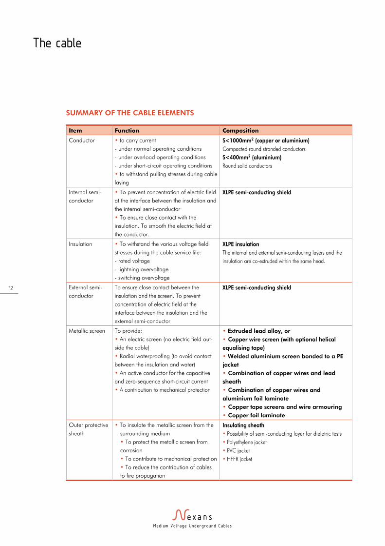
Item Function Composition
Conductor • to carry current
- under normal operating conditions
- under overload operating conditions
- under short-circuit operating conditions
• to withstand pulling stresses during cable
laying
S<1000mm2 (copper or aluminium)
Compacted round stranded conductors
S<400mm2 (aluminium)
Round solid conductors
Internal semi-
conductor
• To prevent concentration of electric field
at the interface between the insulation and
the internal semi-conductor
• To ensure close contact with the
insulation. To smooth the electric field at
the conductor.
XLPE semi-conducting shield
Insulation • To withstand the various voltage field
stresses during the cable service life:
- rated voltage
- lightning overvoltage
- switching overvoltage
XLPE insulation
The internal and external semi-conducting layers and the
insulation are co-extruded within the same head.
External semi-
conductor
To ensure close contact between the
insulation and the screen. To prevent
concentration of electric field at the
interface between the insulation and the
external semi-conductor
XLPE semi-conducting shield
Metallic screen To provide:
• An electric screen (no electric field out-
side the cable)
• Radial waterproofing (to avoid contact
between the insulation and water)
• An active conductor for the capacitive
and zero-sequence short-circuit current
• A contribution to mechanical protection
• Extruded lead alloy, or
• Copper wire screen (with optional helical
equalising tape)
• Welded aluminium screen bonded to a PE
jacket
• Combination of copper wires and lead
sheath
• Combination of copper wires and
aluminium foil laminate
• Copper tape screens and wire armouring
• Copper foil laminate
Outer protective
sheath
• To insulate the metallic screen from the
surrounding medium
• To protect the metallic screen from
corrosion
• To contribute to mechanical protection
• To reduce the contribution of cables
to fire propagation
Insulating sheath
• Possibility of semi-conducting layer for dieletric tests
• Polyethylene jacket
• PVC jacket
• HFFR jacket
SUMMARY OF THE CABLE ELEMENTS
Med ium Vo l tage Underground Cab les
13
The cable
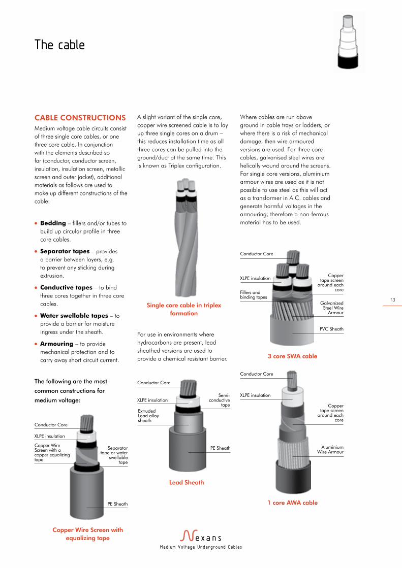
CABLE CONSTRUCTIONS
Medium voltage cable circuits consist
of three single core cables, or one
three core cable. In conjunction
with the elements described so
far (conductor, conductor screen,
insulation, insulation screen, metallic
screen and outer jacket), additional
materials as follows are used to
make up different constructions of the
cable:
l Bedding – fillers and/or tubes to
build up circular profile in three
core cables.
l Separator tapes – provides
a barrier between layers, e.g.
to prevent any sticking during
extrusion.
l Conductive tapes – to bind
three cores together in three core
cables.
l Water swellable tapes – to
provide a barrier for moisture
ingress under the sheath.
l Armouring – to provide
mechanical protection and to
carry away short circuit current.
The following are the most
common constructions for
medium voltage:
A slight variant of the single core,
copper wire screened cable is to lay
up three single cores on a drum –
this reduces installation time as all
three cores can be pulled into the
ground/duct at the same time. This
is known as Triplex configuration.
For use in environments where
hydrocarbons are present, lead
sheathed versions are used to
provide a chemical resistant barrier.
Where cables are run above
ground in cable trays or ladders, or
where there is a risk of mechanical
damage, then wire armoured
versions are used. For three core
cables, galvanised steel wires are
helically wound around the screens.
For single core versions, aluminium
armour wires are used as it is not
possible to use steel as this will act
as a transformer in A.C. cables and
generate harmful voltages in the
armouring; therefore a non-ferrous
material has to be used.
Copper Wire Screen with
equalizing tape
Copper Wire Screen with a copper equalizing tape
Conductor Core
XLPE insulation
Separator tape or water
swellable tape
PE Sheath
Single core cable in triplex
formation
Semi- conductive
tape
Conductor Core
XLPE insulation
Extruded Lead alloy sheath
PE Sheath
Lead Sheath
3 core SWA cable
1 core AWA cable
Conductor Core
XLPE insulation
Fillers and binding tapes
Copper tape screen
around each core
Galvanized Steel Wire
Armour
PVC Sheath
Aluminium Wire Armour
Conductor Core
Copper tape screen
around each core
XLPE insulation
Med ium Vo l tage Underground Cab les
14
The cable
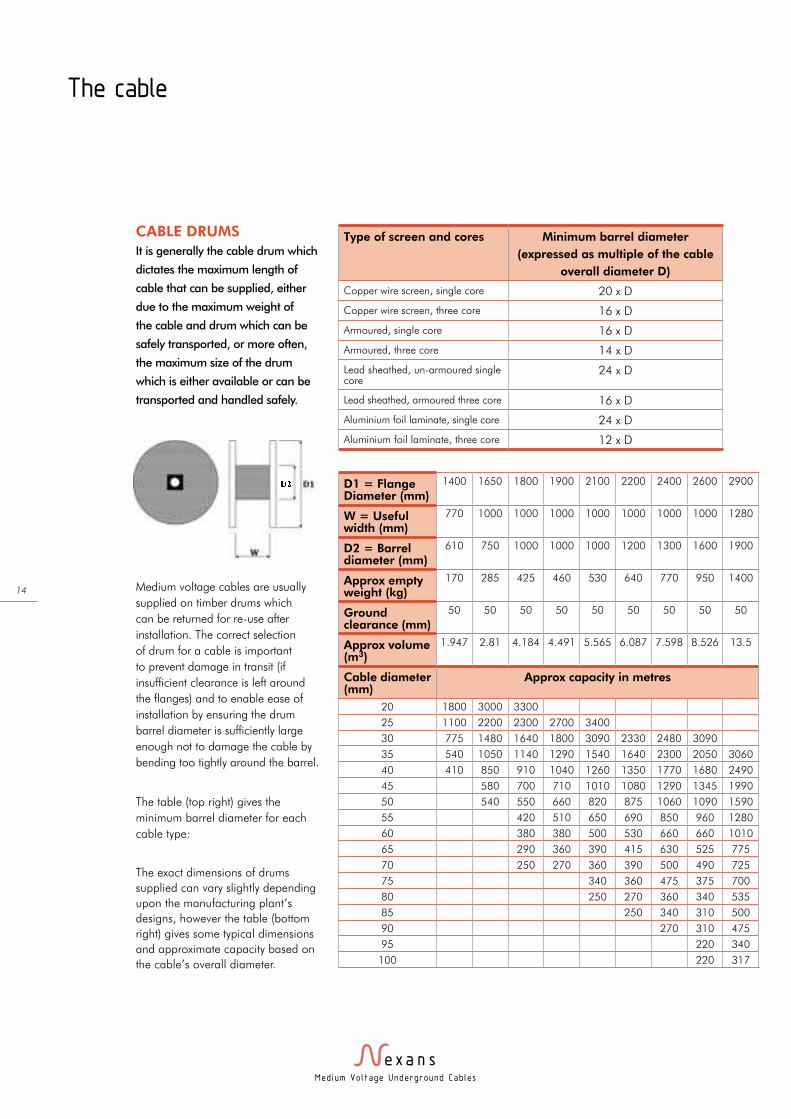
CABLE DRUMS
It is generally the cable drum which
dictates the maximum length of
cable that can be supplied, either
due to the maximum weight of
the cable and drum which can be
safely transported, or more often,
the maximum size of the drum
which is either available or can be
transported and handled safely.
Medium voltage cables are usually
supplied on timber drums which
can be returned for re-use after
installation. The correct selection
of drum for a cable is important
to prevent damage in transit (if
insufficient clearance is left around
the flanges) and to enable ease of
installation by ensuring the drum
barrel diameter is sufficiently large
enough not to damage the cable by
bending too tightly around the barrel.
The table (top right) gives the
minimum barrel diameter for each
cable type:
The exact dimensions of drums
supplied can vary slightly depending
upon the manufacturing plant’s
designs, however the table (bottom
right) gives some typical dimensions
and approximate capacity based on
the cable’s overall diameter.
Type of screen and cores Minimum barrel diameter
(expressed as multiple of the cable
overall diameter D)
Copper wire screen, single core 20 x D
Copper wire screen, three core 16 x D
Armoured, single core 16 x D
Armoured, three core 14 x D
Lead sheathed, un-armoured single core
24 x D
Lead sheathed, armoured three core 16 x D
Aluminium foil laminate, single core 24 x D
Aluminium foil laminate, three core 12 x D
D1 = Flange Diameter (mm)
1400 1650 1800 1900 2100 2200 2400 2600 2900
W = Useful width (mm)
770 1000 1000 1000 1000 1000 1000 1000 1280
D2 = Barrel diameter (mm)
610 750 1000 1000 1000 1200 1300 1600 1900
Approx empty weight (kg)
170 285 425 460 530 640 770 950 1400
Ground clearance (mm)
50 50 50 50 50 50 50 50 50
Approx volume (m3)
1.947 2.81 4.184 4.491 5.565 6.087 7.598 8.526 13.5
Cable diameter (mm)
Approx capacity in metres
20 1800 3000 3300
25 1100 2200 2300 2700 3400
30 775 1480 1640 1800 3090 2330 2480 3090
35 540 1050 1140 1290 1540 1640 2300 2050 3060
40 410 850 910 1040 1260 1350 1770 1680 2490
45 580 700 710 1010 1080 1290 1345 1990
50 540 550 660 820 875 1060 1090 1590
55 420 510 650 690 850 960 1280
60 380 380 500 530 660 660 1010
65 290 360 390 415 630 525 775
70 250 270 360 390 500 490 725
75 340 360 475 375 700
80 250 270 360 340 535
85 250 340 310 500
90 270 310 475
95 220 340
100 220 317
Med ium Vo l tage Underground Cab les
15
The cable
CABLE TESTS
FOLLOWING
PRODUCTION
The tests carried out on cables can
be grouped into three categories:
1. Routine tests
2. Sample tests
3. Type tests
The actual details for each test
vary according to the specification
followed (e.g IEC 60502 or
BS 7870), however they generally
include the following:
Routine tests
These non-destructive tests are
normally carried out on each
manufactured length of cable, and
include:
l Measurement of electrical
resistance of conductors
l Partial discharge test
l Voltage tests, typically a test of
4 x U° between core and metallic
screen for 15 minutes
l D.C. voltage test on sheath
Sample tests
These tests, which can be
destructive, are carried out
on one length or drum from a
manufacturing run:
l Conductor examination
l Dimensions check
l 4 hour voltage test at 4 x U°
l Hot set test (on XLPE insulation)
Type tests
These tests are carried out to
validate the cable design, materials
and/or production process and are
done usually once at the beginning
of the supply of a particular cable
design. The tests can be divided into
two categories, electrical and non-
electrical:
Electrical Type tests
l Partial discharge test.
l Bending test.
l Tan σ measurement.
l Heat cycle test followed by partial
discharge measurement.
l Impulse withstand voltage test.
l Long term voltage test.
Non-Electrical type tests:
l Dimension checks.
l Mechanical properties before and
after ageing (tensile strength and
elongation).
l Thermoplastic properties (hot
pressure tests and behaviour at
low temperatures).
l Other tests.
The cables manufactured by
Nexans’ sites are usually tested
in accordance with international
standards IEC 60502. Test
programmes in accordance with
national standards such as
BS 7870 or BS 6622 or even client
specific specifications may also be
performed.
Med ium Vo l tage Underground Cab les
16
Accessories
The medium voltage network
system, including the cable
and its accessories, has two
functions: the dielectric and the
current function. The current
function transmits the power
and the dielectric function
insulates this system.
CONNECTORS AND
LUGS
Connectors and lugs are used to
connect conductors with each other
or to connect them to other parts of
the installation. In addition to the
nominal current, these connectors
must be able to carry specified short
circuit currents. They have been
designed taking into account the
thermal and mechanical stresses
at the connecting point together
with the nominal and short circuit
currents.
General requirements for
connector
l as compact as possible.
l low and constant ohm
resistance to avoid voltage
drops and to keep heating as
low as possible.
l sufficient mechanical
resistance to accept the
mechanical forces.
l corrosion resistance.
l long life expectancy, will not
wear in case of overcharge or
short circuit.
l easy and reliable installation.
l able to use with different
conductor materials, and
no need for surveillance.
Heating modifies the behaviour of
the cable link, and thus reduces
the life expectancy.
Factors that lead to a rise in
temperature of a cable connection:
l quality loss.
l thermal capacity.
l heat dissipation.
l thermal radiation.
l convection.
The higher the temperature,
the higher the expansion. This
leads to a loss of contact force,
an increased oxide formation
and a loss of contact surface,
which again leads to a higher
temperature.
The quality of a connection can be
improved by:
l a good coordination between
the conductor, the connector
and the tools.
l a respect for the installation
characteristics prescribed by
the supplier.
l a thorough cleaning of the
contacts and meticulous work.
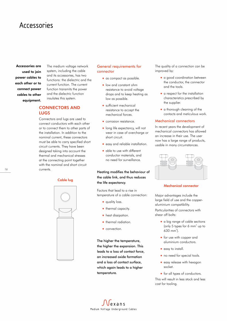
Mechanical connectors
In recent years the development of
mechanical connectors has allowed
an increase in their use. The user
now has a large range of products,
usable in many circumstances.
Major advantages include the
large field of use and the copper-
aluminium compatibility.
Particularities of connectors with
shear off bolts:
l a big range of cable sections
(only 5 types for 6 mm² up to
630 mm²).
l for use with copper and
aluminium conductors.
l easy to install.
l no need for special tools.
l easy release with hexagon
socket.
l for all types of conductors.
This will result in less stock and less
cost for tooling.
Accessories are
used to join
power cables to
each other or to
connect power
cables to other
equipment.
Mechanical connector
Cable lug
Med ium Vo l tage Underground Cab les
17
Crimped connectors
When using the crimping technique,
it is important to note that the
products (connectors, ferrules and
lugs) must be compatible with
the conductor type and the tools
used. Each product has a specific
standard. The producer must ensure
a perfect connection between the
different elements. The crimping
method must be adapted to the type
of conductor and its material.
ELECTRICAL FIELDS
The electrical field control in an
accessory depends on the way
this field is controlled in the cable.
In paper insulated, belted cables
up to 10 kV, there is a common
electrical field and a common
metallic screen. Due to the higher
stresses, there must be greater
distances between the phases and
the earthing. The electrical field is
not directly controlled.
All other medium and high voltage
cables have a stress controlling
screen. The electrical field is guided
by two semi-conductive cylinders,
internally and externally to the
insulation, and thus becomes very
homogeneous.
When connecting cables, the
different layers of the medium
voltage cable have to be removed.
The electrical field distribution is
disturbed by removing the metallic
and semi-conductive screen. This
will lead to partial discharges and
in the short or long term to a break
down. For this reason it is necessary
to fit an electrical field control device
to the cable at voltages higher than
6 kV. These connecting and field
controlling devices are called power
cable accessories.
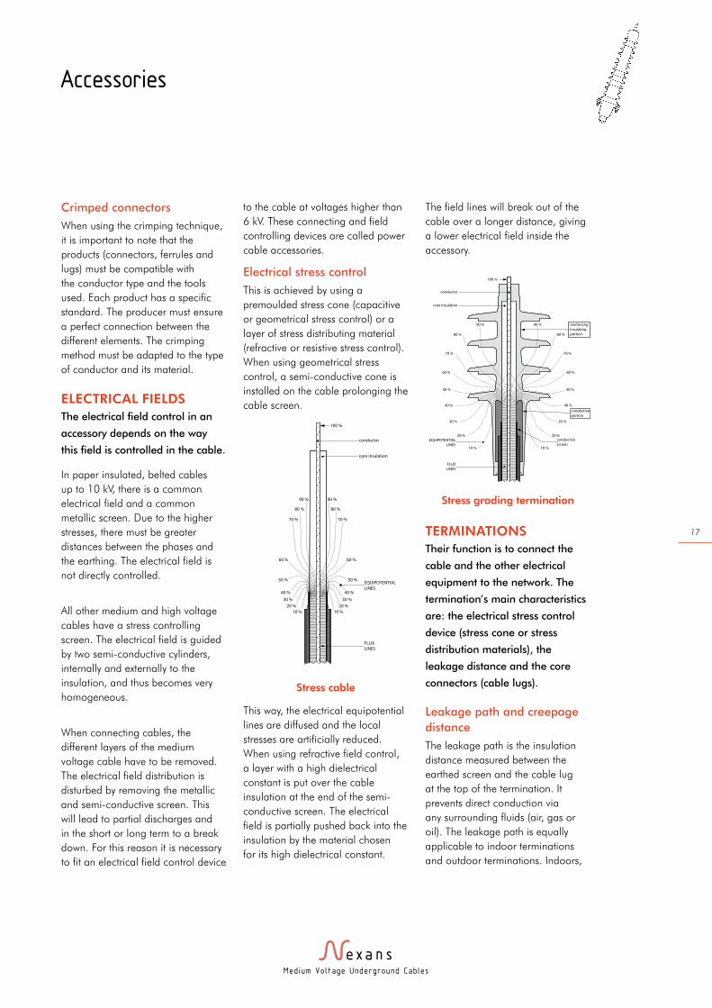
Electrical stress control
This is achieved by using a
premoulded stress cone (capacitive
or geometrical stress control) or a
layer of stress distributing material
(refractive or resistive stress control).
When using geometrical stress
control, a semi-conductive cone is
installed on the cable prolonging the
cable screen.
This way, the electrical equipotential
lines are diffused and the local
stresses are artificially reduced.
When using refractive field control,
a layer with a high dielectrical
constant is put over the cable
insulation at the end of the semi-
conductive screen. The electrical
field is partially pushed back into the
insulation by the material chosen
for its high dielectrical constant.
The field lines will break out of the
cable over a longer distance, giving
a lower electrical field inside the
accessory.
TERMINATIONS
Their function is to connect the
cable and the other electrical
equipment to the network. The
termination’s main characteristics
are: the electrical stress control
device (stress cone or stress
distribution materials), the
leakage distance and the core
connectors (cable lugs).
Leakage path and creepage
distance
The leakage path is the insulation
distance measured between the
earthed screen and the cable lug
at the top of the termination. It
prevents direct conduction via
any surrounding fluids (air, gas or
oil). The leakage path is equally
applicable to indoor terminations
and outdoor terminations. Indoors,
Accessories
60 %
80 %
70 %
90 %
50 %
40 %
20 %
10 %
30 %
60 %
80 %
70 %
90 %
50 %
40 %
20 %
10 %
30 %
100 %
FLUX
LINES
core insulation
conductor
EQUIPOTENTIAL
LINES
Stress cable
60 %
50 %
40 %
80 %
70 %
90 %
20 %
10 %
30 %
conductive
screen
60 %
50 %
40 %
80 %
70 %
90 %
20 %
10 %
conductive
portion
30 %
100 %
FLUX
LINES
EQUIPOTENTIAL
LINES
core insulation
conductor
reinforcing
insulating
portion
Stress grading termination
Med ium Vo l tage Underground Cab les
18
Accessories
the leakage path is almost
unaffected by environmental factors,
but outdoors, the leakage path
has to be designed in line with
environmental considerations, such
as relative humidity, salinity and
atmospheric pollution.
The leakage path of a termination
is determined by multiplying the
IEC 60815 standard pollution
factor expressed in mm/kV and the
maximum grid voltage. Pollution
factor (in mm/kV) x maximum
voltage (in kV) = minimum
termination leakage path (in mm).
The construction of a termination
depends on the voltage, the cable
type and its location, eg. indoor and
outdoor.
Slip-on termination
Since the 1960s slip-on terminations
have been in use. The installation
of these premoulded accessories is
very easy and simple. Due to their
great elasticity they can be installed
on all single or three core polymeric
cables for use indoors and outdoors.
The field control is done by a
semi-conductive stress cone inside
the (EPDM or silicone) rubber
termination housing (capacitive
stress control).
Heat-shrinkable termination
These terminations have co-existed
for many years with the slip-on
terminations. These extruded sleeves
are heated by a flame and retract
around a cable. The sleeves can
contain a hot melt glue that liquefies
when heated and adheres to the
outer cable sheath. This creates
a water tightness that protects the
penetration of humidity in the cable.
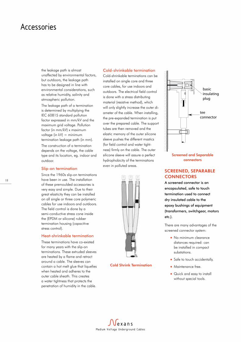
Cold-shrinkable termination
Cold-shrinkable terminations can be
installed on single core and three
core cables, for use indoors and
outdoors. The electrical field control
is done with a stress distributing
material (resistive method), which
will only slightly increase the outer di-
ameter of the cable. When installing,
the pre-expanded termination is put
over the prepared cable. The support
tubes are then removed and the
elastic memory of the outer silicone
sleeve pushes the different mastics
(for field control and water tight-
ness) firmly on the cable. The outer
silicone sleeve will assure a perfect
hydrophobicity of the terminations
even in polluted areas.
SCREENED, SEPARABLE
CONNECTORS
A screened connector is an
encapsulated, safe to touch
termination used to connect
dry insulated cable to the
epoxy bushings of equipment
(transformers, switchgear, motors
etc.).
There are many advantages of the
screened connector system:
l No minimum clearance
distances required: can
be installed in compact
substations.
l Safe to touch accidentally.
l Maintenance free.
l Quick and easy to install
without special tools.
tee
connector
basic
insulating
plug
Cold Shrink Termination
Screened and Separable
connectors
Med ium Vo l tage Underground Cab les
19
l Easy to disconnect.
l Fully watertight.
l Degree of protection IP67:
dust tight and immersion in
water.
l Resistant to UV, ozone,
chemicals, mechanical abuse.
l Temperature range from
-30°C to +110°C.
l Offers many test options:
capacitive test point, cable test.
l A complete range from 12 kV
up to 42 kV.
l Can be used outdoors without
cable box.
For use in potentially explosive
atmospheres, ATEX certified systems
are available. Manufacturers
who apply the provisions of this
directive can sell without any further
requirements with respect to the risks
covered. The directive covers a large
range of equipment, including those
used on fixed offshore platforms,
in petrochemical plants, mines,
flour mills and other areas where a
potential explosive atmosphere may
be present.
The outer cone system (as described
in CENELEC 50180 and 50181)
has several standard interfaces for
the different current classes:
l Interface A: up to 250 A with
a plug-in connection.
l Interface B: up to 400 A with
a plug-in connection.
l Interface C: up to 630 A
(1250 A) with a bolted
connection.
l Interface D: up to 800 A with
a bolted connection.
l Interface E: up to 1250 A with
a bolted connection.
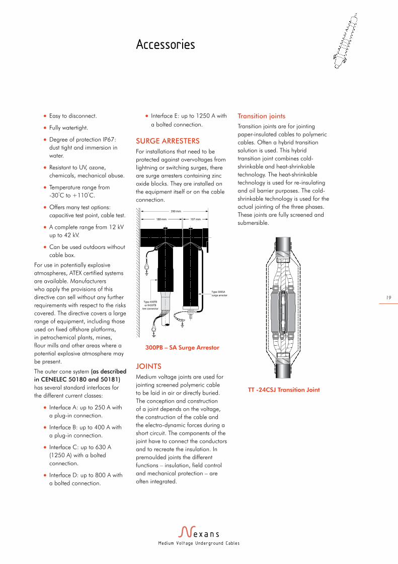
SURGE ARRESTERS
For installations that need to be
protected against overvoltages from
lightning or switching surges, there
are surge arresters containing zinc
oxide blocks. They are installed on
the equipment itself or on the cable
connection.
JOINTS
Medium voltage joints are used for
jointing screened polymeric cable
to be laid in air or directly buried.
The conception and construction
of a joint depends on the voltage,
the construction of the cable and
the electro-dynamic forces during a
short circuit. The components of the
joint have to connect the conductors
and to recreate the insulation. In
premoulded joints the different
functions – insulation, field control
and mechanical protection – are
often integrated.
Transition joints
Transition joints are for jointing
paper-insulated cables to polymeric
cables. Often a hybrid transition
solution is used. This hybrid
transition joint combines cold-
shrinkable and heat-shrinkable
technology. The heat-shrinkable
technology is used for re-insulating
and oil barrier purposes. The cold-
shrinkable technology is used for the
actual jointing of the three phases.
These joints are fully screened and
submersible.
Accessories
290 mm
180 mm 107 mm
Type 430TB
or K430TB
tee connector
Type 300SA
surge arrester
300PB – SA Surge Arrestor
TT -24CSJ Transition Joint
Med ium Vo l tage Underground Cab les
20
Installation
In-service
experience has
shown that the
reliability of
underground
networks is
dependent
on the careful
transportation,
drum handling
and quality
of the cable
installation on
the site.
CABLE DRUM HANDLING
Cable drums should be handled with care using
correct mechanical handling equipment for the lifting
and movement of drums on site.
Drums should be stored on firm flat ground on the
edge of the flanges, never laid flat on the ground.
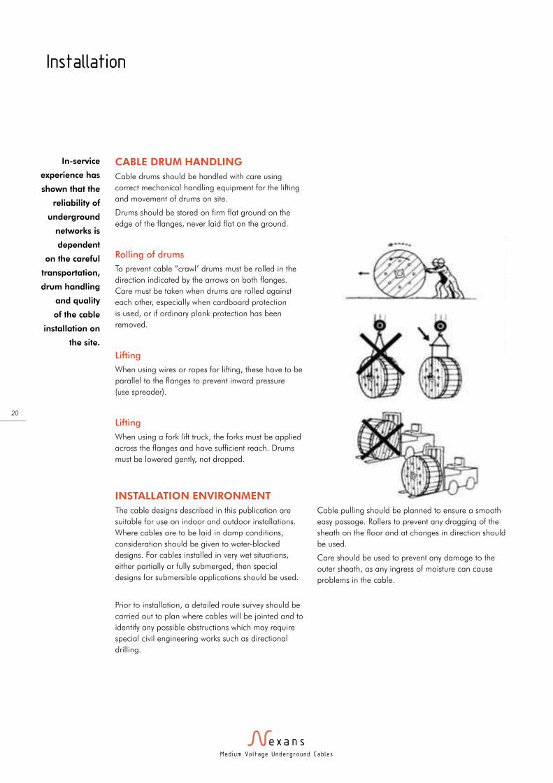
Rolling of drums
To prevent cable “crawl’ drums must be rolled in the
direction indicated by the arrows on both flanges.
Care must be taken when drums are rolled against
each other, especially when cardboard protection
is used, or if ordinary plank protection has been
removed.
Lifting
When using wires or ropes for lifting, these have to be
parallel to the flanges to prevent inward pressure
(use spreader).
Lifting
When using a fork lift truck, the forks must be applied
across the flanges and have sufficient reach. Drums
must be lowered gently, not dropped.
INSTALLATION ENVIRONMENT
The cable designs described in this publication are
suitable for use on indoor and outdoor installations.
Where cables are to be laid in damp conditions,
consideration should be given to water-blocked
designs. For cables installed in very wet situations,
either partially or fully submerged, then special
designs for submersible applications should be used.
Prior to installation, a detailed route survey should be
carried out to plan where cables will be jointed and to
identify any possible obstructions which may require
special civil engineering works such as directional
drilling.
Cable pulling should be planned to ensure a smooth
easy passage. Rollers to prevent any dragging of the
sheath on the floor and at changes in direction should
be used.
Care should be used to prevent any damage to the
outer sheath, as any ingress of moisture can cause
problems in the cable.
Med ium Vo l tage Underground Cab les
21
Installation
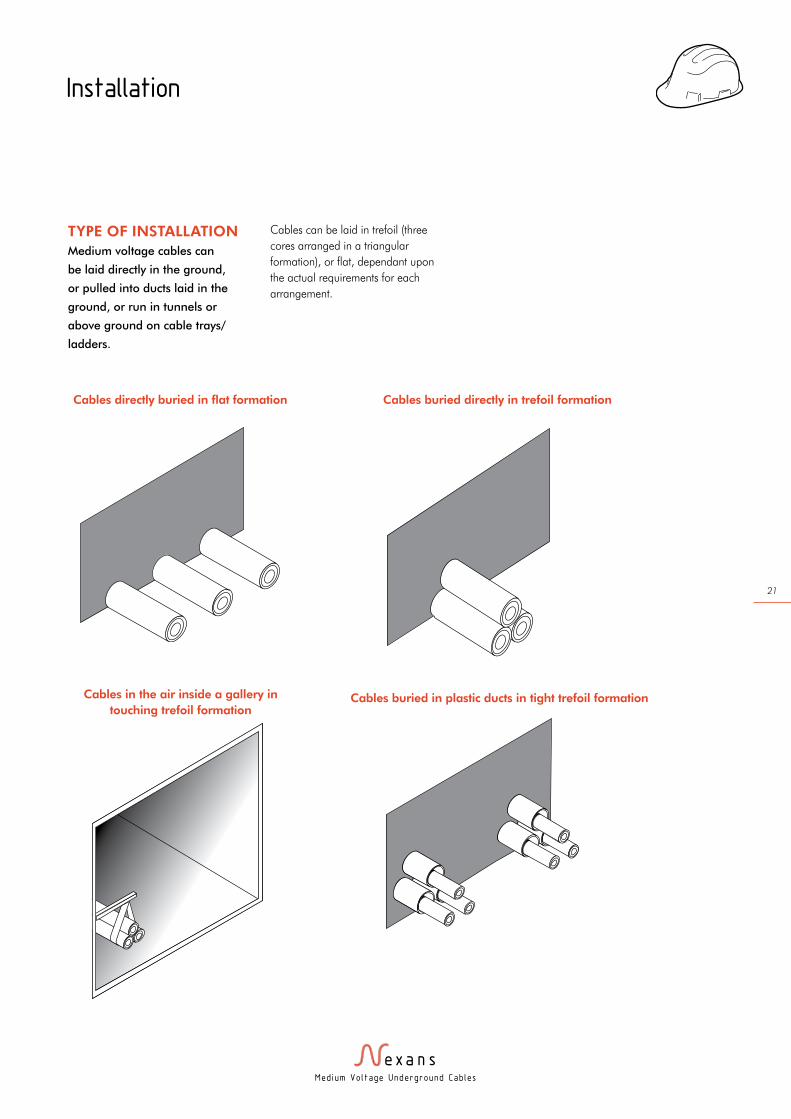
Cables directly buried in flat formation
TYPE OF INSTALLATION
Medium voltage cables can
be laid directly in the ground,
or pulled into ducts laid in the
ground, or run in tunnels or
above ground on cable trays/
ladders.
Cables can be laid in trefoil (three
cores arranged in a triangular
formation), or flat, dependant upon
the actual requirements for each
arrangement.
Cables in the air inside a gallery in
touching trefoil formation
Cables buried directly in trefoil formation
Cables buried in plastic ducts in tight trefoil formation

Med ium Vo l tage Underground Cab les
22
Installation
A2 Cables
per phase
B In air R1 Y1 B1
B2 Y2 R2
R1 Y1 B1
R2 Y2 B2
2 Cables
per phase
In air
groundR1
Y1 B1
R2
B2 Y2
2 Cables
per phase
In air
groundR1 Y1 B1 B2 Y2 R2
3 Cables
per phase
In air
groundR1
Y1 B1
R2
B2 Y2
R3
Y3 B3
4 Cables
per phase
In air
groundR1
Y1 B1
R2
B2 Y2
R3
Y3 B3
R4
B4 Y4
INSTALLATION
TEMPERATURE
To avoid the risk of damage during
installation, cables should only be
pulled when the temperature is
above 0°C, and have stood for over
24hours above this temperature
to ensure the cables are fully
acclimatised.
Cables with HFFR sheaths have
better performances at low
temperature and can be safely
installed at temperatures down to
-10°C.
Cables with PVC sheaths should
be installed at temperatures below
35°C to prevent any possible sheath
damage.
Where multiple single core circuits are laid, care must be taken to ensure how the
phases are connected to ensure a balanced current distribution is achieved.

Med ium Vo l tage Underground Cab les
23
Installation
MAXIMUM PERMISSIBLE
TENSILE FORCE DURING
PULLING
The tensile force applied during the
pulling of the cables into position
must be compatible with the
mechanical strength of the cables. It
is advisable to use a dynamometer
to continuously check the pulling
tension to ensure the forces do not
exceed the recommended guidelines
as follows:
l 50N /mm2 for cables with copper
conductors
l 30N /mm2 for cables with
aluminium conductors
In the case of three core cables,
the cross sectional area of all three
cores is taken into account.
For example, 3 x 120mm2 Copper
cable = (3x120x50) = 18,000N
(1800kg)
When pulling cable using a cable
grip on the sheath, the maximum
permissible tensile force is same as
that on the conductor as calculated
above. However, following
installation it is recommended to
cut off two metres beyond the point
where the cable grip is attached and
check for no signs of stretching on
the sheath.
MINIMUM BENDING
RADIUS DURING
INSTALLATION
Cables should not be bent
to a radius smaller than the
recommended values (table, top
right).
Type of screen and cores
Minimum bending radius during installation
(expressed as multiple of the cable overall
diameter D)
Minimum bending radius after
installation (cables fixed to a former)
Copper wire screen, single core
20 x D 15 x D
Copper wire screen, three core
16 x D 12 x D
Armoured, single core 16 x D 12 x D
Armoured, three core 14 x D 10 x D
Lead sheathed, un-armoured single core
24 x D 20 x D
Lead sheathed, armoured three core
16 x D 12 x D
Aluminium foil laminate, single core
24 x D 20 x D
Aluminium foil laminate, three core
12 x D 10 x D
CABLE SUPPORT
SPACING
Cable systems need to be
adequately fixed to a surface to
prevent problems with expansion
and contraction during service, and
to contain the cables in the event
of a short-circuit which creates high
electro-dynamic loads between
the phases, which would create
uncontrollable damage to the cable
and surrounding area without the
necessary fixings.
It is important to design a cable
support system which provides
the necessary clamping force to
withstand the forces generated in
service and short-circuit conditions.
The table below gives some
preliminary indications of the
necessary spacings for cables
system, however, any final design
should be made for each specific
installation taking all factors into
consideration.
Aluminium conductors Support spacing
Diameter of cable Horizontal (mm) Vertical (mm)
15-20 1200 550
20-40 2000 600
40-60 3000 900
>60 4000 1300
Copper conductors Horizontal (mm) Vertical (mm)
15-20 400 550
20-40 450 600
40-60 700 900
>60 1100 1300
Med ium Vo l tage Underground Cab les
24
Installation
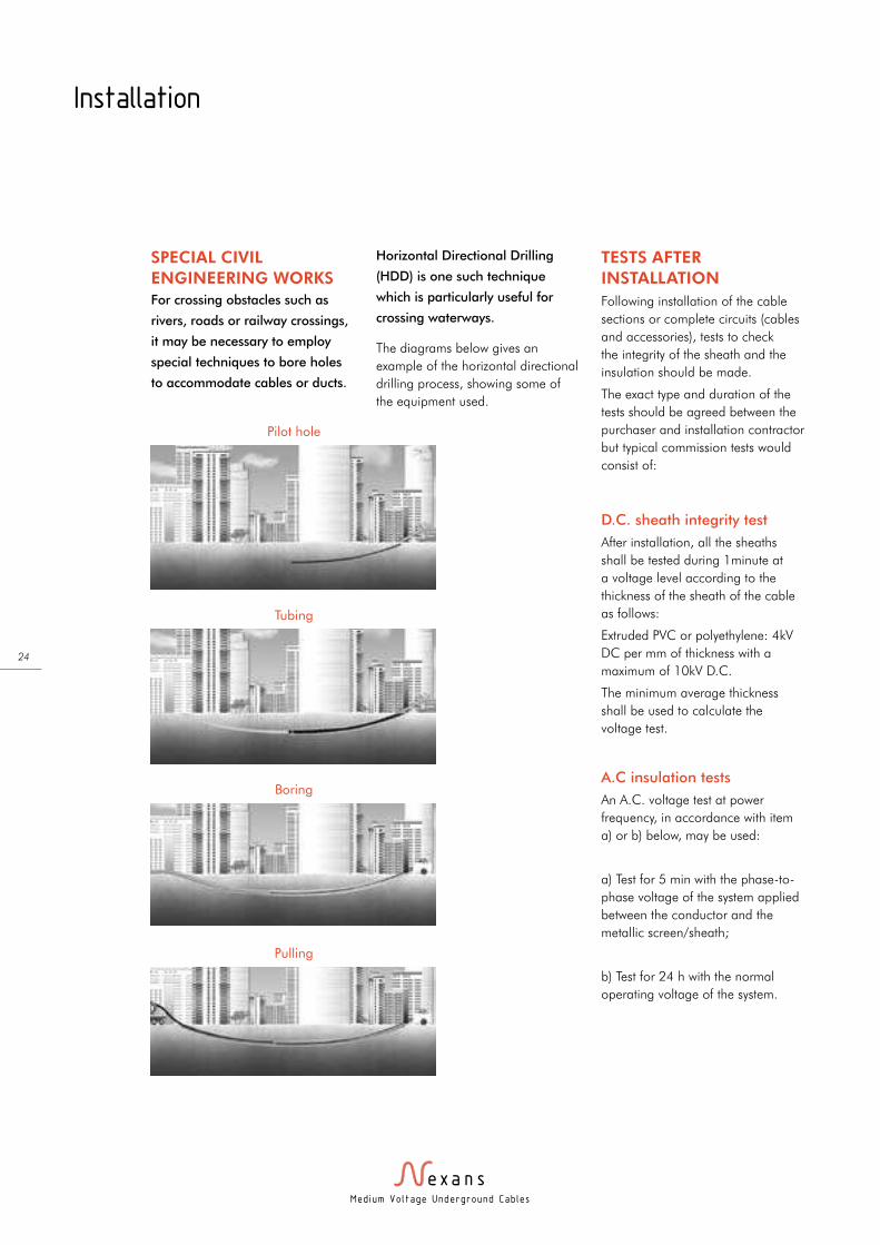
SPECIAL CIVIL
ENGINEERING WORKS
For crossing obstacles such as
rivers, roads or railway crossings,
it may be necessary to employ
special techniques to bore holes
to accommodate cables or ducts.
Horizontal Directional Drilling
(HDD) is one such technique
which is particularly useful for
crossing waterways.
The diagrams below gives an
example of the horizontal directional
drilling process, showing some of
the equipment used.
TESTS AFTER
INSTALLATION
Following installation of the cable
sections or complete circuits (cables
and accessories), tests to check
the integrity of the sheath and the
insulation should be made.
The exact type and duration of the
tests should be agreed between the
purchaser and installation contractor
but typical commission tests would
consist of:
D.C. sheath integrity test
After installation, all the sheaths
shall be tested during 1minute at
a voltage level according to the
thickness of the sheath of the cable
as follows:
Extruded PVC or polyethylene: 4kV
DC per mm of thickness with a
maximum of 10kV D.C.
The minimum average thickness
shall be used to calculate the
voltage test.
A.C insulation tests
An A.C. voltage test at power
frequency, in accordance with item
a) or b) below, may be used:
a) Test for 5 min with the phase-to-
phase voltage of the system applied
between the conductor and the
metallic screen/sheath;
b) Test for 24 h with the normal
operating voltage of the system.
Pilot hole
Tubing
Boring
Pulling

Med ium Vo l tage Underground Cab les
25
The figures given in the following
tables allow an initial estimation to
be made of the required cable cross
section area and type.
However, they cannot replace a
full calculation made by Nexans
Technical experts which will take
into account specific conditions for
individual installations.
CONDUCTOR CROSS
SECTION AND
CALCULATION OF THE
CONTINUOUS CURRENT
RATING
The conductor cross section is
determined by the current carry
capacity of each phase according to
the following formula:
I = S in amperes
√3 x U
where:
I = current rating
S = apparent power of the line in
kVA
U=the rated phase to phase voltage
The conductor cross section must be
of sufficient size so that the heating
of the cable insulation due to the
resistance and dielectric losses
generated in the cable is compatible
to its resistance to heat.
The maximum rated temperatures
are as follows for XLPE insulated
cables
Temperature under
rated operating
conditions
90ºC
Temperature under
emergency operating
conditions
105ºC
Temperature in the event of
a short-circuit (< 5 sec)
250ºC
If the cables are buried in the
ground and loaded continuously,
consideration should be given to the
possibility of a local increase in soil
thermal resistivity due to moisture
migration, making it desirable to
reduce the maximum conductor
operating temperature to 80°C.
The current ratings in the
following tables are given for
three standard methods of
installation; laid direct, in single
way ducts or in air. They need
to be adjusted according to
the actual parameters for each
installation:
l the arrangement of the cables
(trefoil or flat formation).
l the depth of laying.
l the thermal resistivity of the
ground (expressed in K m/W).
l the temperature of the
surrounding ground.
l the temperature of the ambient air.
l the proximity effect from adjacent
circuits.
l the screen bonding arrangement
(i.e. single point or solid bonding).
l the material and diameters of
ducts.
The correction factors in the tables
below can be used to determine the
effect on the current ratings:
Thermal resistivity of
the ground K. m/W0.8 1.0 1.2 1.5 2.0 2.5
Correction Factor 1.07 1.02 1.0 0.93 0.89 0.86
Ground
temperature in °C10 15 20 25 30 35 40
Correction Factor 1.03 1.0 0.97 0.93 0.89 0.86 0.82
Air temperature
in °C25 30 35 40 50 55
Correction Factor 1.0 0.95 0.92 0.88 0.78 0.73
Proximity effects distance between
2 circuits (mm)0.15 0.30 0.45 0.60
1 circuit 1.00 1.00 1.00 1.00
2 circuits 0.85 0.89 0.90 0.92
3 circuits 0.75 0.80 0.84 0.86
4 circuits 0.70 0.77 0.80 0.84
Current ratings for copper and aluminium conductors
Laying depth in metres 0.5 0.6 0.8 1.0 1.5 2.0 3.0
Correction Factor 1.05 1.02 1.0 0.97 0.93 0.89 0.86
Med ium Vo l tage Underground Cab les
26
l 3.8/6.6 (7.2) kV Three Core armoured copper conductors 27
l 6.35/11 (12) kV Triplex / Single Core unarmoured copper conductors 28
l 6.35/11 (12) kV Triplex / Single Core unarmoured aluminium conductors 29
l 6.35/11 (12) kV Three Core unarmoured copper conductors 30
l 6.35/11 (12) kV Three Core unarmoured aluminium conductors 31
l 6.35/11 (12) kV Single Core armoured copper conductors 32
l 6.35/11 (12) kV Single Core armoured aluminium conductors 33
l 6.35/11 (12) kV Three Core armoured copper conductors 34
l 6.35/11 (12) kV Three Core armoured aluminium conductors 35
l 8.7/15 (17.5) kV Single Core armoured copper conductors 36
l 8.7/15 (17.5) kV Three Core armoured copper conductors 37
l 12/20 (22) kV Single Core copper unarmoured conductors 38
l 12/20 (22) kV Single Core armoured copper conductors 39
l 12/20 (22) kV Three Core armoured copper conductors 40
l 19/33 (36) kV Single Core unarmoured copper conductors 41
l 19/33 (36) kV Single Core unarmoured aluminium conductors 42
l 19/33 (36) kV Single Core armoured copper conductors 43
l 19/33 (36) kV Three Core armoured copper conductors 44
Technical Specifications
Med ium Vo l tage Underground Cab les
27
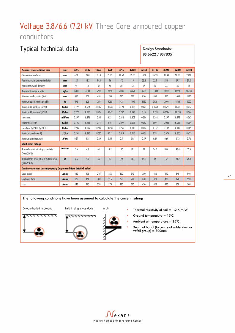
Voltage 3.8/6.6 (7.2) kV Three Core armoured copper
conductors
Typical technical data
Nominal cross-sectional area mm² 3x25 3x35 3x50 3x70 3x95 3x120 3x150 3x185 3x240 3x300 3x400
Diameter over conductor mm 6.00 7.00 8.10 9.80 11.50 12.80 14.30 15.90 18.40 20.50 23.20
Approximate diameter over insulation mm 12.1 13.2 14.3 16 17.7 19 20.5 22.1 24.8 27.7 31.2
Approximate overall diameter mm 45 48 52 56 60 64 67 70 76 85 93
Approximate weight of cable kg/m 3600 4100 5200 6150 7300 8450 9550 11000 13350 16950 20450
Minimum bending radius (static) mm 550 600 650 700 750 800 850 850 950 1050 1150
Maximum pulling tension on cable kg 375 525 750 1050 1425 1800 2250 2775 3600 4500 5000
Maximum DC resistance @20°C Ω/km 0.727 0.524 0.387 0.268 0.193 0.153 0.124 0.0991 0.0754 0.0601 0.047
Maximum AC resistance@ 90°C Ω/km 0.927 0.668 0.494 0.342 0.247 0.196 0.16 0.128 0.0986 0.0798 0.064
Inductance mH/km 0.397 0.376 0.35 0.331 0.316 0.303 0.294 0.288 0.297 0.272 0.267
Reactance@50Hz Ω/km 0.125 0.118 0.11 0.104 0.099 0.095 0.093 0.091 0.088 0.085 0.084
Impedance @ 50Hz @ 90°C Ω/km 0.936 0.679 0.506 0.358 0.266 0.218 0.184 0.157 0.132 0.117 0.105
Maximum capacitance (C) µF/km 0.261 0.293 0.325 0.371 0.419 0.458 0.497 0.531 0.575 0.605 0.631
Maximum charging current A/km 0.31 0.35 0.39 0.44 0.5 0.55 0.59 0.64 0.69 0.72 0.76
Short circuit ratings
1 second short-circuit rating of conductor
(90 to 250°C)
26/08/2009 3.5 4.9 6.7 9.7 13.5 17.1 21 26.3 34.6 43.4 55.6
1 second short-circuit rating of metallic screen
(80 to 250°C)
kA 3.5 4.9 6.7 9.7 12.5 13.4 14.1 15 16.4 23.2 25.4
Continuous current carrying capacity (as per conditions detailed below)
Direct buried Amps 140 170 210 255 300 340 380 430 490 540 590
Single way ducts Amps 125 150 180 215 255 290 330 370 425 470 520
In air Amps 145 175 220 270 330 375 430 490 570 650 700
Design Standards:
BS 6622 / BS7835
The following conditions have been assumed to calculate the current ratings:
• Thermal resistivity of soil = 1.2 K.m/W
• Ground temperature = 15°C
• Ambient air temperature = 25°C
• Depth of burial (to centre of cable, duct or trefoil group) = 800mm
Directly buried in ground Laid in single way ducts In air
Med ium Vo l tage Underground Cab les
28
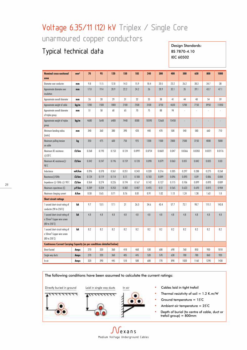
Voltage 6.35/11 (12) kV Triplex / Single Core
unarmoured copper conductors
Typical technical data
Nominal cross-sectional
area
mm² 70 95 120 150 185 240 300 400 500 630 800 1000
Diameter over conductor mm 9.8 11.5 12.8 14.3 15.9 18.4 20.5 23.2 26.2 30.3 34.7 38
Approximate diameter over
insulation
mm 17.8 19.4 20.9 22.2 24.2 26 28.9 32.1 35 39.1 43.7 47.1
Approximate overall diameter mm 26 28 29 31 32 35 38 41 44 48 54 59
Approximate weight of cable kg/m 1200 1500 1800 2100 2500 3100 3750 4650 5700 7150 8950 11050
Approximate overall diameter
of triplex group
mm 51 58 60 65 70 75 88 94 - - - -
Approximate weight of triplex
group
kg/m 4680 5640 6480 7440 8580 10590 12660 15450 - - - -
Minimum bending radius
(static)
mm 340 360 380 390 420 440 470 500 540 580 660 710
Maximum pulling tension
on cable
kg 350 475 600 750 925 1200 1500 2000 2500 3150 4000 5000
Maximum DC resistance
@20°C
Ω/km 0.268 0.193 0.153 0.124 0.0991 0.0754 0.0601 0.047 0.0366 0.0283 0.0221 0.0176
Maximum AC resistance@
90°C
Ω/km 0.342 0.247 0.196 0.159 0.128 0.098 0.079 0.063 0.051 0.042 0.035 0.03
Inductance mH/km 0.396 0.378 0.361 0.351 0.343 0.328 0.316 0.305 0.297 0.288 0.275 0.268
Reactance@50Hz Ω/km 0.124 0.119 0.114 0.11 0.108 0.103 0.099 0.096 0.093 0.09 0.086 0.084
Impedance @ 50Hz @ 90°C Ω/km 0.364 0.274 0.226 0.194 0.167 0.142 0.127 0.115 0.106 0.099 0.093 0.089
Maximum capacitance (C) µF/km 0.289 0.324 0.353 0.382 0.407 0.455 0.51 0.565 0.623 0.693 0.815 0.904
Maximum charging current A/km 0.58 0.65 0.71 0.76 0.81 0.91 1.02 1.13 1.24 1.38 1.63 1.8
Short circuit ratings
1 second short-circuit rating of
conductor (90 to 250°C)
kA 9.7 13.5 17.1 21 26.3 34.6 43.4 57.7 72.1 90.7 115.1 143.8
1 second short-circuit rating of
a 35mm2 Copper wire screen
(80 to 250°C)
kA 4.8 4.8 4.8 4.8 4.8 4.8 4.8 4.8 4.8 4.8 4.8 4.8
1 second short-circuit rating of
a 50mm2 Copper wire screen
(80 to 250°C)
kA 8.2 8.2 8.2 8.2 8.2 8.2 8.2 8.2 8.2 8.2 8.2 8.2
Continuous Current Carrying Capacity (as per conditions detailed below)
Direct buried Amps 270 320 360 410 460 530 600 690 760 850 930 1010
Single way ducts Amps 270 320 360 405 445 520 570 630 700 780 860 920
In air Amps 320 390 445 510 580 680 770 890 1020 1160 1290 1430
Design Standards:
BS 7870-4.10
IEC 60502
The following conditions have been assumed to calculate the current ratings:
• Cables laid in tight trefoil
• Thermal resistivity of soil = 1.2 K.m/W
• Ground temperature = 15°C
• Ambient air temperature = 25°C
• Depth of burial (to centre of cable, duct or trefoil group) = 800mm
Directly buried in ground Laid in single way ducts In air

Med ium Vo l tage Underground Cab les
29
Design Standards:
BS 7870-4.10
IEC 60502
Voltage 6.35/11 (12) kV Triplex / Single Core
unarmoured aluminium conductors
Typical technical data
Nominal cross-sectional
area
mm² 70 95 120 150 185 240 300 400 500 630 800 1000
Diameter over conductor mm 9.8 11.5 12.8 14.3 15.9 18.4 20.5 23.2 26.2 30.3 34.7 38
Approximate diameter over
insulation
mm 17.8 19.4 20.9 22.2 24.2 26 28.9 32.1 35 39.1 43.7 47.1
Approximate overall diameter mm 26 28 29 31 32 35 38 41 44 48 54 59
Approximate weight of cable kg/m 1050 1150 1300 1400 1550 1800 2050 2400 2800 3300 4050 4800
Approximate overall diameter
of triplex group
mm 51 58 60 65 70 75 88 94 - - - -
Approximate weight of triplex
group
kg/m 3150 3450 3900 4200 4650 5400 6150 7200 - - - -
Minimum bending radius
(static)
mm 340 360 380 390 420 440 470 500 540 580 660 710
Maximum pulling tension
on cable
kg 210 475 600 750 925 1200 1500 2000 2500 3150 4000 5000
Maximum DC resistance
@20°C
Ω/km 0.443 0.320 0.253 0.206 0.164 0.125 0.100 0.078 0.061 0.047 0.037 0.029
Maximum AC resistance@
90°C
Ω/km 0.568 0.411 0.325 0.265 0.211 0.161 0.130 0.102 0.080 0.063 0.051 0.042
Inductance mH/km 0.422 0.401 0.385 0.377 0.364 0.348 0.336 0.325 0.320 0.310 0.295 0.287
Reactance@50Hz Ω/km 0.133 0.126 0.121 0.119 0.114 0.109 0.106 0.102 0.100 0.097 0.093 0.090
Impedance @ 50Hz @ 90°C Ω/km 0.583 0.429 0.347 0.29 0.24 0.195 0.167 0.144 0.128 0.116 0.106 0.1
Maximum capacitance (C) µF/km 0.289 0.324 0.353 0.382 0.417 0.465 0.51 0.565 0.623 0.693 0.815 0.904
Maximum charging current A/km 0.58 0.65 0.71 0.76 0.83 0.93 1.02 1.13 1.24 1.38 1.63 1.8
Short circuit ratings
1 second short-circuit rating of
conductor (90 to 250°C)
kA 6.4 8.9 11.3 13.9 17.4 22.9 28.7 36.8 46.4 59.9 >60 >60
1 second short-circuit rating of
a 35mm2 Copper wire screen
(80 to 250°C)
kA 4.8 4.8 4.8 4.8 4.8 4.8 4.8 4.8 4.8 4.8 4.8 4.8
1 second short-circuit rating of
a 50mm2 Copper wire screen
(80 to 250°C)
kA 8.2 8.2 8.2 8.2 8.2 8.2 8.2 8.2 8.2 8.2 8.2 8.2
Continuous current carrying capacity (as per conditions detailed below)
Direct buried Amps 210 250 280 320 360 415 475 540 610 680 770 850
Single way ducts Amps 215 255 285 315 350 405 455 510 570 640 710 790
In air Amps 240 300 335 380 435 510 600 700 810 930 1070 1210
The following conditions have been assumed to calculate the current ratings:
• Cables laid in tight trefoil
• Thermal resistivity of soil = 1.2 K.m/W
• Ground temperature = 15°C
• Ambient air temperature = 25°C
• Depth of burial (to centre of cable, duct or trefoil group) = 800mm
Directly buried in ground Laid in single way ducts In air
Med ium Vo l tage Underground Cab les
30
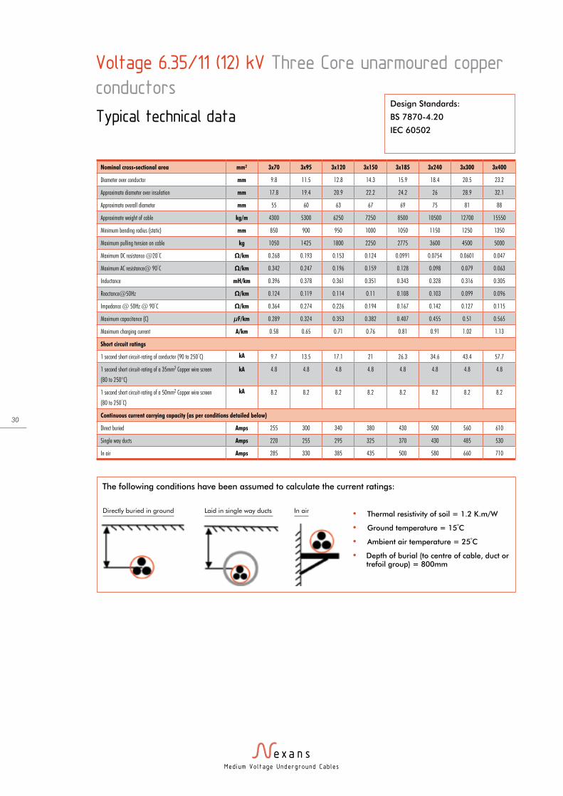
Voltage 6.35/11 (12) kV Three Core unarmoured copper
conductors
Typical technical dataDesign Standards:
BS 7870-4.20
IEC 60502
Nominal cross-sectional area mm² 3x70 3x95 3x120 3x150 3x185 3x240 3x300 3x400
Diameter over conductor mm 9.8 11.5 12.8 14.3 15.9 18.4 20.5 23.2
Approximate diameter over insulation mm 17.8 19.4 20.9 22.2 24.2 26 28.9 32.1
Approximate overall diameter mm 55 60 63 67 69 75 81 88
Approximate weight of cable kg/m 4300 5300 6250 7250 8500 10500 12700 15550
Minimum bending radius (static) mm 850 900 950 1000 1050 1150 1250 1350
Maximum pulling tension on cable kg 1050 1425 1800 2250 2775 3600 4500 5000
Maximum DC resistance @20°C Ω/km 0.268 0.193 0.153 0.124 0.0991 0.0754 0.0601 0.047
Maximum AC resistance@ 90°C Ω/km 0.342 0.247 0.196 0.159 0.128 0.098 0.079 0.063
Inductance mH/km 0.396 0.378 0.361 0.351 0.343 0.328 0.316 0.305
Reactance@50Hz Ω/km 0.124 0.119 0.114 0.11 0.108 0.103 0.099 0.096
Impedance @ 50Hz @ 90°C Ω/km 0.364 0.274 0.226 0.194 0.167 0.142 0.127 0.115
Maximum capacitance (C) µF/km 0.289 0.324 0.353 0.382 0.407 0.455 0.51 0.565
Maximum charging current A/km 0.58 0.65 0.71 0.76 0.81 0.91 1.02 1.13
Short circuit ratings
1 second short circuit-rating of conductor (90 to 250°C) kA 9.7 13.5 17.1 21 26.3 34.6 43.4 57.7
1 second short circuit-rating of a 35mm2 Copper wire screen
(80 to 250°C)
kA 4.8 4.8 4.8 4.8 4.8 4.8 4.8 4.8
1 second short circuit-rating of a 50mm2 Copper wire screen
(80 to 250°C)
kA 8.2 8.2 8.2 8.2 8.2 8.2 8.2 8.2
Continuous current carrying capacity (as per conditions detailed below)
Direct buried Amps 255 300 340 380 430 500 560 610
Single way ducts Amps 220 255 295 325 370 430 485 530
In air Amps 285 330 385 435 500 580 660 710
The following conditions have been assumed to calculate the current ratings:
• Thermal resistivity of soil = 1.2 K.m/W
• Ground temperature = 15°C
• Ambient air temperature = 25°C
• Depth of burial (to centre of cable, duct or trefoil group) = 800mm
Directly buried in ground Laid in single way ducts In air
Med ium Vo l tage Underground Cab les
31
Design Standards:
BS 7870-4.20
IEC 60502
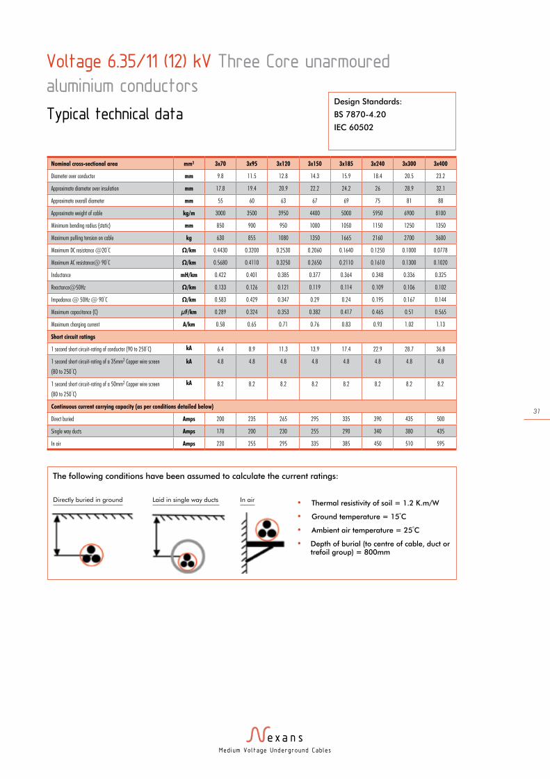
Voltage 6.35/11 (12) kV Three Core unarmoured
aluminium conductors
Typical technical data
Nominal cross-sectional area mm² 3x70 3x95 3x120 3x150 3x185 3x240 3x300 3x400
Diameter over conductor mm 9.8 11.5 12.8 14.3 15.9 18.4 20.5 23.2
Approximate diameter over insulation mm 17.8 19.4 20.9 22.2 24.2 26 28.9 32.1
Approximate overall diameter mm 55 60 63 67 69 75 81 88
Approximate weight of cable kg/m 3000 3500 3950 4400 5000 5950 6900 8100
Minimum bending radius (static) mm 850 900 950 1000 1050 1150 1250 1350
Maximum pulling tension on cable kg 630 855 1080 1350 1665 2160 2700 3600
Maximum DC resistance @20°C Ω/km 0.4430 0.3200 0.2530 0.2060 0.1640 0.1250 0.1000 0.0778
Maximum AC resistance@ 90°C Ω/km 0.5680 0.4110 0.3250 0.2650 0.2110 0.1610 0.1300 0.1020
Inductance mH/km 0.422 0.401 0.385 0.377 0.364 0.348 0.336 0.325
Reactance@50Hz Ω/km 0.133 0.126 0.121 0.119 0.114 0.109 0.106 0.102
Impedance @ 50Hz @ 90°C Ω/km 0.583 0.429 0.347 0.29 0.24 0.195 0.167 0.144
Maximum capacitance (C) µF/km 0.289 0.324 0.353 0.382 0.417 0.465 0.51 0.565
Maximum charging current A/km 0.58 0.65 0.71 0.76 0.83 0.93 1.02 1.13
Short circuit ratings
1 second short circuit-rating of conductor (90 to 250°C) kA 6.4 8.9 11.3 13.9 17.4 22.9 28.7 36.8
1 second short circuit-rating of a 35mm2 Copper wire screen
(80 to 250°C)
kA 4.8 4.8 4.8 4.8 4.8 4.8 4.8 4.8
1 second short circuit-rating of a 50mm2 Copper wire screen
(80 to 250°C)
kA 8.2 8.2 8.2 8.2 8.2 8.2 8.2 8.2
Continuous current carrying capacity (as per conditions detailed below)
Direct buried Amps 200 235 265 295 335 390 435 500
Single way ducts Amps 170 200 230 255 290 340 380 435
In air Amps 220 255 295 335 385 450 510 595
The following conditions have been assumed to calculate the current ratings:
• Thermal resistivity of soil = 1.2 K.m/W
• Ground temperature = 15°C
• Ambient air temperature = 25°C
• Depth of burial (to centre of cable, duct or trefoil group) = 800mm
Directly buried in ground Laid in single way ducts In air
Med ium Vo l tage Underground Cab les
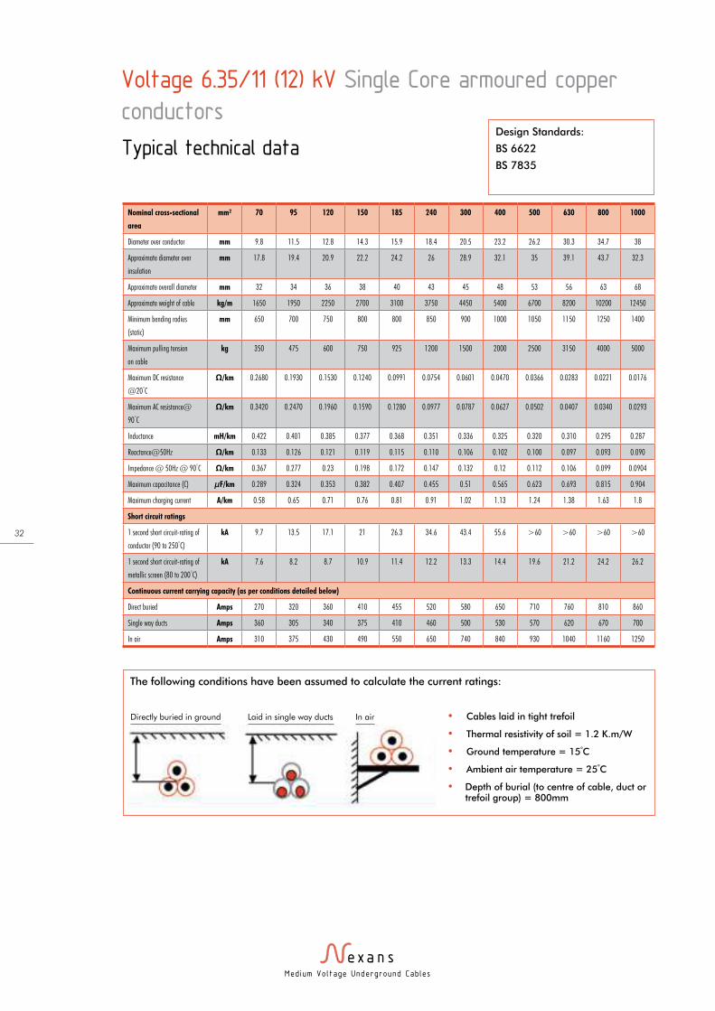
32
Voltage 6.35/11 (12) kV Single Core armoured copper
conductors
Typical technical data
Nominal cross-sectional
area
mm² 70 95 120 150 185 240 300 400 500 630 800 1000
Diameter over conductor mm 9.8 11.5 12.8 14.3 15.9 18.4 20.5 23.2 26.2 30.3 34.7 38
Approximate diameter over
insulation
mm 17.8 19.4 20.9 22.2 24.2 26 28.9 32.1 35 39.1 43.7 32.3
Approximate overall diameter mm 32 34 36 38 40 43 45 48 53 56 63 68
Approximate weight of cable kg/m 1650 1950 2250 2700 3100 3750 4450 5400 6700 8200 10200 12450
Minimum bending radius
(static)
mm 650 700 750 800 800 850 900 1000 1050 1150 1250 1400
Maximum pulling tension
on cable
kg 350 475 600 750 925 1200 1500 2000 2500 3150 4000 5000
Maximum DC resistance
@20°C
Ω/km 0.2680 0.1930 0.1530 0.1240 0.0991 0.0754 0.0601 0.0470 0.0366 0.0283 0.0221 0.0176
Maximum AC resistance@
90°C
Ω/km 0.3420 0.2470 0.1960 0.1590 0.1280 0.0977 0.0787 0.0627 0.0502 0.0407 0.0340 0.0293
Inductance mH/km 0.422 0.401 0.385 0.377 0.368 0.351 0.336 0.325 0.320 0.310 0.295 0.287
Reactance@50Hz Ω/km 0.133 0.126 0.121 0.119 0.115 0.110 0.106 0.102 0.100 0.097 0.093 0.090
Impedance @ 50Hz @ 90°C Ω/km 0.367 0.277 0.23 0.198 0.172 0.147 0.132 0.12 0.112 0.106 0.099 0.0904
Maximum capacitance (C) µF/km 0.289 0.324 0.353 0.382 0.407 0.455 0.51 0.565 0.623 0.693 0.815 0.904
Maximum charging current A/km 0.58 0.65 0.71 0.76 0.81 0.91 1.02 1.13 1.24 1.38 1.63 1.8
Short circuit ratings
1 second short circuit-rating of
conductor (90 to 250°C)
kA 9.7 13.5 17.1 21 26.3 34.6 43.4 55.6 >60 >60 >60 >60
1 second short circuit-rating of
metallic screen (80 to 200°C)
kA 7.6 8.2 8.7 10.9 11.4 12.2 13.3 14.4 19.6 21.2 24.2 26.2
Continuous current carrying capacity (as per conditions detailed below)
Direct buried Amps 270 320 360 410 455 520 580 650 710 760 810 860
Single way ducts Amps 360 305 340 375 410 460 500 530 570 620 670 700
In air Amps 310 375 430 490 550 650 740 840 930 1040 1160 1250
Design Standards:
BS 6622
BS 7835
The following conditions have been assumed to calculate the current ratings:
• Cables laid in tight trefoil
• Thermal resistivity of soil = 1.2 K.m/W
• Ground temperature = 15°C
• Ambient air temperature = 25°C
• Depth of burial (to centre of cable, duct or trefoil group) = 800mm
Directly buried in ground Laid in single way ducts In air
Med ium Vo l tage Underground Cab les
33
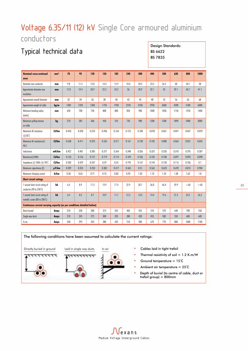
Nominal cross-sectional
area
mm² 70 95 120 150 185 240 300 400 500 630 800 1000
Diameter over conductor mm 9.8 11.5 12.8 14.3 15.9 18.4 20.5 23.2 26.2 30 34.7 38
Approximate diameter over
insulation
mm 17.8 19.4 20.9 22.2 24.2 26 28.9 32.1 35 39.1 43.7 47.1
Approximate overall diameter mm 32 34 36 38 40 43 45 48 53 56 63 68
Approximate weight of cable kg/m 1200 1350 1500 1750 1950 2250 2550 2950 3600 4200 5100 6000
Minimum bending radius
(static)
mm 650 700 750 800 800 850 900 1000 1050 1150 1250 1400
Maximum pulling tension
on cable
kg 210 285 360 450 555 720 900 1200 1500 1890 2400 3000
Maximum DC resistance
@20°C
Ω/km 0.443 0.320 0.253 0.206 0.164 0.125 0.100 0.078 0.061 0.047 0.037 0.029
Maximum AC resistance@
90°C
Ω/km 0.568 0.411 0.325 0.265 0.211 0.161 0.130 0.102 0.080 0.063 0.051 0.042
Inductance mH/km 0.422 0.401 0.385 0.377 0.364 0.348 0.336 0.325 0.320 0.310 0.295 0.287
Reactance@50Hz Ω/km 0.133 0.126 0.121 0.119 0.114 0.109 0.106 0.102 0.100 0.097 0.093 0.090
Impedance @ 50Hz @ 90°C Ω/km 0.583 0.429 0.347 0.29 0.24 0.195 0.167 0.144 0.128 0.116 0.106 0.1
Maximum capacitance (C) µF/km 0.289 0.324 0.353 0.382 0.417 0.465 0.51 0.565 0.623 0.693 0.815 0.904
Maximum charging current A/km 0.58 0.65 0.71 0.76 0.83 0.93 1.02 1.13 1.24 1.38 1.63 1.8
Short circuit ratings
1 second short circuit-rating of
conductor (90 to 250°C)
kA 6.4 8.9 11.3 13.9 17.4 22.9 28.7 36.8 46.4 59.9 >60 >60
1 second short circuit-rating of
metallic screen (80 to 200°C)
kA 6.4 8.2 8.7 10.9 11.7 12.5 13.3 14.4 19.6 21.2 24.2 26.2
Continuous current carrying capacity (as per conditions detailed below)
Direct buried Amps 210 250 280 315 355 405 455 510 570 640 700 760
Single way ducts Amps 210 245 275 300 335 380 420 455 500 550 600 640
In air Amps 240 295 335 380 435 510 580 670 770 880 1000 1100
Voltage 6.35/11 (12) kV Single Core armoured aluminium
conductors
Typical technical dataDesign Standards:
BS 6622
BS 7835
The following conditions have been assumed to calculate the current ratings:
• Cables laid in tight trefoil
• Thermal resistivity of soil = 1.2 K.m/W
• Ground temperature = 15°C
• Ambient air temperature = 25°C
• Depth of burial (to centre of cable, duct or trefoil group) = 800mm
Directly buried in ground Laid in single way ducts In air
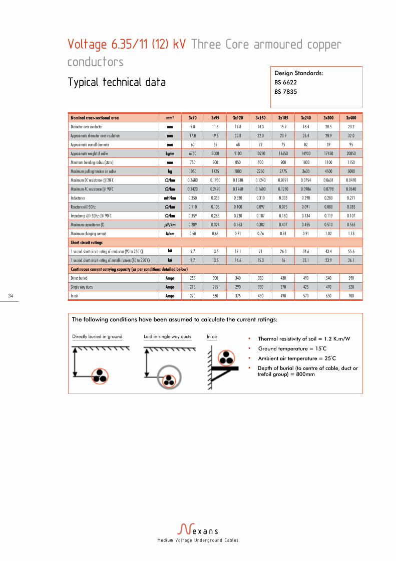
Med ium Vo l tage Underground Cab les
34
Voltage 6.35/11 (12) kV Three Core armoured copper
conductors
Typical technical dataDesign Standards:
BS 6622
BS 7835
Nominal cross-sectional area mm² 3x70 3x95 3x120 3x150 3x185 3x240 3x300 3x400
Diameter over conductor mm 9.8 11.5 12.8 14.3 15.9 18.4 20.5 23.2
Approximate diameter over insulation mm 17.8 19.5 20.8 22.3 23.9 26.4 28.9 32.0
Approximate overall diameter mm 60 65 68 72 75 82 89 95
Approximate weight of cable kg/m 6750 8000 9100 10250 11650 14900 17450 20850
Minimum bending radius (static) mm 750 800 850 900 900 1000 1100 1150
Maximum pulling tension on cable kg 1050 1425 1800 2250 2775 3600 4500 5000
Maximum DC resistance @20°C Ω/km 0.2680 0.1930 0.1530 0.1240 0.0991 0.0754 0.0601 0.0470
Maximum AC resistance@ 90°C Ω/km 0.3420 0.2470 0.1960 0.1600 0.1280 0.0986 0.0798 0.0640
Inductance mH/km 0.350 0.333 0.320 0.310 0.303 0.290 0.280 0.271
Reactance@50Hz Ω/km 0.110 0.105 0.100 0.097 0.095 0.091 0.088 0.085
Impedance @ 50Hz @ 90°C Ω/km 0.359 0.268 0.220 0.187 0.160 0.134 0.119 0.107
Maximum capacitance (C) µF/km 0.289 0.324 0.353 0.382 0.407 0.455 0.510 0.565
Maximum charging current A/km 0.58 0.65 0.71 0.76 0.81 0.91 1.02 1.13
Short circuit ratings
1 second short circuit-rating of conductor (90 to 250°C) kA 9.7 13.5 17.1 21 26.3 34.6 43.4 55.6
1 second short circuit-rating of metallic screen (80 to 250°C) kA 9.7 13.5 14.6 15.3 16 22.1 23.9 26.1
Continuous current carrying capacity (as per conditions detailed below)
Direct buried Amps 255 300 340 380 430 490 540 590
Single way ducts Amps 215 255 290 330 370 425 470 520
In air Amps 270 330 375 430 490 570 650 700
The following conditions have been assumed to calculate the current ratings:
• Thermal resistivity of soil = 1.2 K.m/W
• Ground temperature = 15°C
• Ambient air temperature = 25°C
• Depth of burial (to centre of cable, duct or trefoil group) = 800mm
Directly buried in ground Laid in single way ducts In air

Med ium Vo l tage Underground Cab les
35
Voltage 6.35/11 (12) kV Three Core armoured aluminium
conductors
Typical technical dataDesign Standards:
BS 6622
BS 7835
Nominal cross-sectional area mm² 3x70 3x95 3x120 3x150 3x185 3x240 3x300 3x400
Diameter over conductor mm 9.8 11.5 12.8 14.3 15.9 18.4 20.5 23.2
Approximate diameter over insulation mm 17.8 19.5 20.8 22.3 23.9 26.4 28.9 32.0
Approximate overall diameter mm 60 65 68 72 75 82 89 95
Approximate weight of cable kg/m 5400 6150 6800 7400 8250 10400 11650 13400
Minimum bending radius (static) mm 750 800 850 900 900 1000 1100 1150
Maximum pulling tension on cable kg 630 855 1080 1350 1665 2160 2700 3600
Maximum DC resistance @20°C Ω/km 0.443 0.320 0.253 0.206 0.164 0.125 0.100 0.078
Maximum AC resistance@ 90°C Ω/km 0.568 0.411 0.325 0.265 0.211 0.162 0.130 0.102
Inductance mH/km 0.350 0.333 0.320 0.310 0.301 0.289 0.280 0.271
Reactance@50Hz Ω/km 0.110 0.105 0.100 0.970 0.094 0.091 0.088 0.085
Impedance @ 50Hz @ 90°C Ω/km 0.579 0.424 0.340 0.282 0.231 0.185 0.157 0.133
Maximum capacitance (C) µF/km 0.289 0.324 0.353 0.382 0.417 0.465 0.510 0.565
Maximum charging current A/km 0.58 0.65 0.71 0.76 0.83 0.93 1.02 1.13
Short circuit ratings
1 second short circuit-rating of conductor (90 to 250°C) kA 6.4 8.9 11.3 13.9 17.4 22.9 28.7 36.9
1 second short circuit-rating of metallic screen (80 to 250°C) kA 6.4 8.9 11.3 13.9 16.2 22.5 23.9 26.1
Continuous current carrying capacity (as per conditions detailed below)
Direct buried Amps 195 230 265 300 335 380 435 490
Single way ducts Amps 165 200 225 255 290 335 375 425
In air Amps 210 250 295 330 385 450 510 590
The following conditions have been assumed to calculate the current ratings:
• Thermal resistivity of soil = 1.2 K.m/W
• Ground temperature = 15°C
• Ambient air temperature = 25°C
• Depth of burial (to centre of cable, duct or trefoil group) = 800mm
Directly buried in ground Laid in single way ducts In air
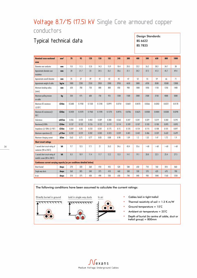
Med ium Vo l tage Underground Cab les
36
Voltage 8.7/15 (17.5) kV Single Core armoured copper
conductors
Typical technical data
Nominal cross-sectional
area
mm² 70 95 120 150 185 240 300 400 500 630 800 1000
Diameter over conductor mm 9.8 11.5 12.8 14.3 15.9 18.4 20.5 23.2 26.2 30.3 34.7 38
Approximate diameter over
insulation
mm 20 21.7 23 24.5 26.1 28.6 31.1 34.2 37.2 41.3 45.7 49.4
Approximate overall diameter mm 35 37 39 41 42 45 47 52 55 59 66 71
Approximate weight of cable kg/m 1800 2200 2550 2850 3300 3950 4650 5800 6950 8500 10500 12800
Minimum bending radius
(static)
mm 650 700 750 800 800 850 900 1000 1050 1150 1250 1400
Maximum pulling tension
on cable
kg 350 475 600 750 925 1200 1500 2000 2500 3150 4000 5000
Maximum DC resistance
@20°C
Ω/km 0.2680 0.1930 0.1530 0.1240 0.0991 0.0754 0.0601 0.0470 0.0366 0.0283 0.0221 0.0178
Maximum AC resistance@
90°C
Ω/km 0.3420 0.2470 0.1960 0.1590 0.1270 0.0976 0.0786 0.0625 0.0500 0.0404 0.0338 0.0290
Inductance mH/km 0.436 0.420 0.403 0.389 0.380 0.363 0.347 0.341 0.329 0.319 0.303 0.295
Reactance@50Hz Ω/km 0.137 0.132 0.126 0.122 0.119 0.114 0.109 0.107 0.103 0.100 0.095 0.093
Impedance @ 50Hz @ 90°C Ω/km 0.369 0.28 0.233 0.201 0.175 0.15 0.135 0.124 0.115 0.108 0.101 0.097
Maximum capacitance (C) µF/km 0.232 0.259 0.282 0.303 0.323 0.359 0.401 0.442 0.486 0.539 0.632 0.699
Maximum charging current A/km 0.63 0.71 0.77 0.83 0.88 0.98 1.09 1.2 1.32 1.47 1.72 1.9
Short circuit ratings
1 second short circuit-rating of
conductor (90 to 250°C)
kA 9.7 13.5 17.1 21 26.3 34.6 43.4 55.6 >60 >60 >60 >60
1 second short circuit-rating of
metallic screen (80 to 200°C)
kA 8.3 10.9 11.4 11.7 12.2 13.3 14.1 19.1 20.8 22.5 25.4 27.5
Continuous current carrying capacity (as per conditions detailed below)
Direct buried Amps 270 320 360 410 455 520 580 650 710 760 810 860
Single way ducts Amps 360 305 340 375 410 460 500 530 570 620 670 700
In air Amps 310 375 430 490 550 650 740 840 930 1040 1160 1250
Design Standards:
BS 6622
BS 7835
The following conditions have been assumed to calculate the current ratings:
• Cables laid in tight trefoil
• Thermal resistivity of soil = 1.2 K.m/W
• Ground temperature = 15°C
• Ambient air temperature = 25°C
• Depth of burial (to centre of cable, duct or trefoil group) = 800mm
Directly buried in ground Laid in single way ducts In air
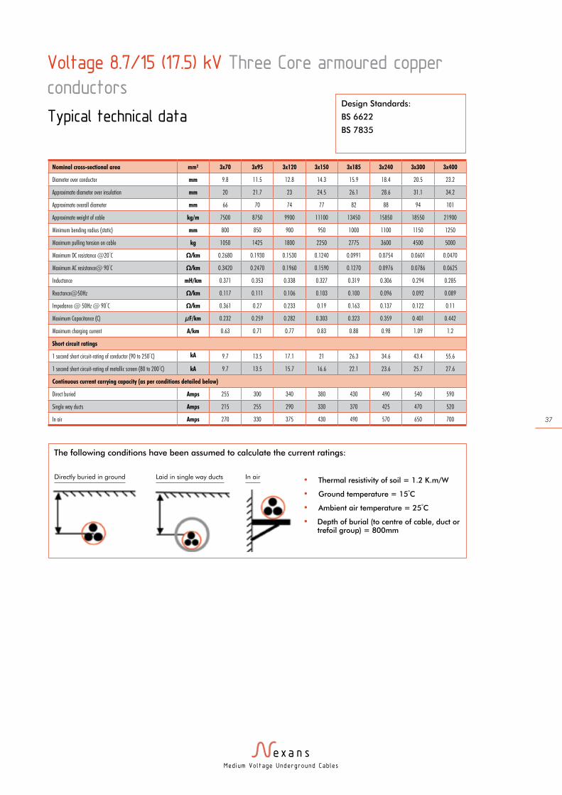
Med ium Vo l tage Underground Cab les
37
Voltage 8.7/15 (17.5) kV Three Core armoured copper
conductors
Typical technical dataDesign Standards:
BS 6622
BS 7835
Nominal cross-sectional area mm² 3x70 3x95 3x120 3x150 3x185 3x240 3x300 3x400
Diameter over conductor mm 9.8 11.5 12.8 14.3 15.9 18.4 20.5 23.2
Approximate diameter over insulation mm 20 21.7 23 24.5 26.1 28.6 31.1 34.2
Approximate overall diameter mm 66 70 74 77 82 88 94 101
Approximate weight of cable kg/m 7500 8750 9900 11100 13450 15850 18550 21900
Minimum bending radius (static) mm 800 850 900 950 1000 1100 1150 1250
Maximum pulling tension on cable kg 1050 1425 1800 2250 2775 3600 4500 5000
Maximum DC resistance @20°C Ω/km 0.2680 0.1930 0.1530 0.1240 0.0991 0.0754 0.0601 0.0470
Maximum AC resistance@ 90°C Ω/km 0.3420 0.2470 0.1960 0.1590 0.1270 0.0976 0.0786 0.0625
Inductance mH/km 0.371 0.353 0.338 0.327 0.319 0.306 0.294 0.285
Reactance@50Hz Ω/km 0.117 0.111 0.106 0.103 0.100 0.096 0.092 0.089
Impedance @ 50Hz @ 90°C Ω/km 0.361 0.27 0.233 0.19 0.163 0.137 0.122 0.11
Maximum Capacitance (C) µF/km 0.232 0.259 0.282 0.303 0.323 0.359 0.401 0.442
Maximum charging current A/km 0.63 0.71 0.77 0.83 0.88 0.98 1.09 1.2
Short circuit ratings
1 second short circuit-rating of conductor (90 to 250°C) kA 9.7 13.5 17.1 21 26.3 34.6 43.4 55.6
1 second short circuit-rating of metallic screen (80 to 200°C) kA 9.7 13.5 15.7 16.6 22.1 23.6 25.7 27.6
Continuous current carrying capacity (as per conditions detailed below)
Direct buried Amps 255 300 340 380 430 490 540 590
Single way ducts Amps 215 255 290 330 370 425 470 520
In air Amps 270 330 375 430 490 570 650 700
The following conditions have been assumed to calculate the current ratings:
• Thermal resistivity of soil = 1.2 K.m/W
• Ground temperature = 15°C
• Ambient air temperature = 25°C
• Depth of burial (to centre of cable, duct or trefoil group) = 800mm
Directly buried in ground Laid in single way ducts In air
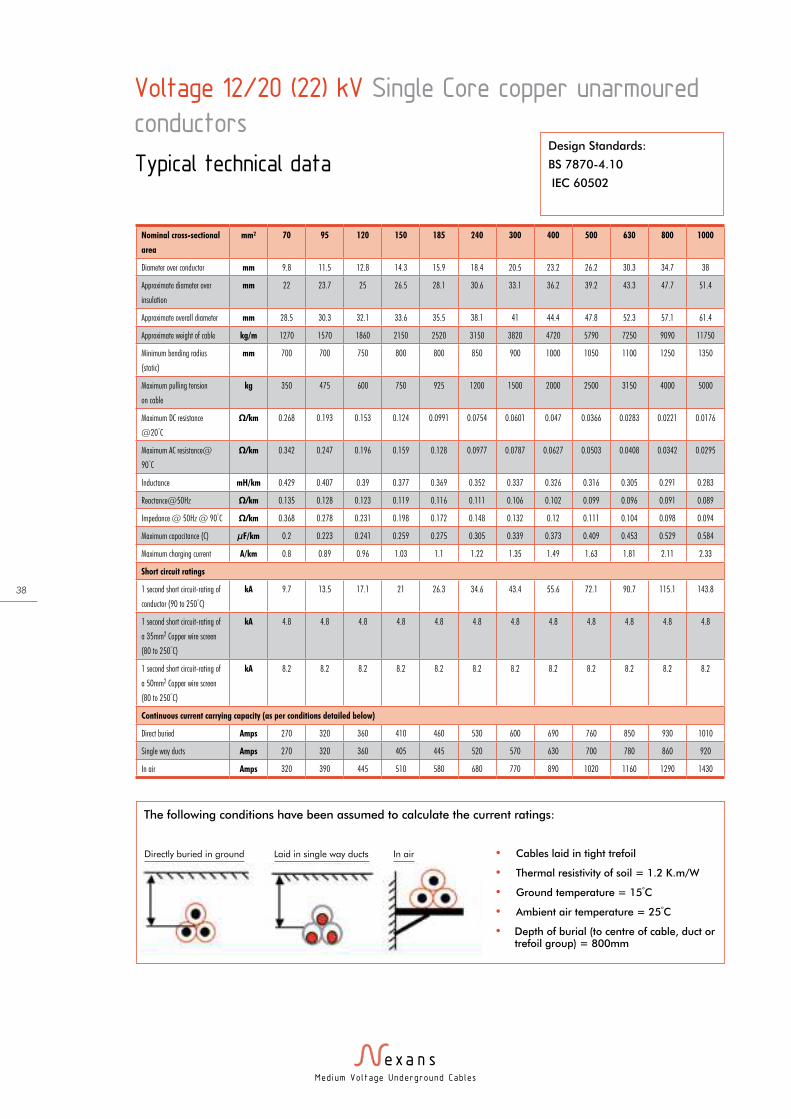
Med ium Vo l tage Underground Cab les
38
Voltage 12/20 (22) kV Single Core copper unarmoured
conductors
Typical technical data
Nominal cross-sectional
area
mm² 70 95 120 150 185 240 300 400 500 630 800 1000
Diameter over conductor mm 9.8 11.5 12.8 14.3 15.9 18.4 20.5 23.2 26.2 30.3 34.7 38
Approximate diameter over
insulation
mm 22 23.7 25 26.5 28.1 30.6 33.1 36.2 39.2 43.3 47.7 51.4
Approximate overall diameter mm 28.5 30.3 32.1 33.6 35.5 38.1 41 44.4 47.8 52.3 57.1 61.4
Approximate weight of cable kg/m 1270 1570 1860 2150 2520 3150 3820 4720 5790 7250 9090 11750
Minimum bending radius
(static)
mm 700 700 750 800 800 850 900 1000 1050 1100 1250 1350
Maximum pulling tension
on cable
kg 350 475 600 750 925 1200 1500 2000 2500 3150 4000 5000
Maximum DC resistance
@20°C
Ω/km 0.268 0.193 0.153 0.124 0.0991 0.0754 0.0601 0.047 0.0366 0.0283 0.0221 0.0176
Maximum AC resistance@
90°C
Ω/km 0.342 0.247 0.196 0.159 0.128 0.0977 0.0787 0.0627 0.0503 0.0408 0.0342 0.0295
Inductance mH/km 0.429 0.407 0.39 0.377 0.369 0.352 0.337 0.326 0.316 0.305 0.291 0.283
Reactance@50Hz Ω/km 0.135 0.128 0.123 0.119 0.116 0.111 0.106 0.102 0.099 0.096 0.091 0.089
Impedance @ 50Hz @ 90°C Ω/km 0.368 0.278 0.231 0.198 0.172 0.148 0.132 0.12 0.111 0.104 0.098 0.094
Maximum capacitance (C) µF/km 0.2 0.223 0.241 0.259 0.275 0.305 0.339 0.373 0.409 0.453 0.529 0.584
Maximum charging current A/km 0.8 0.89 0.96 1.03 1.1 1.22 1.35 1.49 1.63 1.81 2.11 2.33
Short circuit ratings
1 second short circuit-rating of
conductor (90 to 250°C)
kA 9.7 13.5 17.1 21 26.3 34.6 43.4 55.6 72.1 90.7 115.1 143.8
1 second short circuit-rating of
a 35mm2 Copper wire screen
(80 to 250°C)
kA 4.8 4.8 4.8 4.8 4.8 4.8 4.8 4.8 4.8 4.8 4.8 4.8
1 second short circuit-rating of
a 50mm2 Copper wire screen
(80 to 250°C)
kA 8.2 8.2 8.2 8.2 8.2 8.2 8.2 8.2 8.2 8.2 8.2 8.2
Continuous current carrying capacity (as per conditions detailed below)
Direct buried Amps 270 320 360 410 460 530 600 690 760 850 930 1010
Single way ducts Amps 270 320 360 405 445 520 570 630 700 780 860 920
In air Amps 320 390 445 510 580 680 770 890 1020 1160 1290 1430
Design Standards:
BS 7870-4.10
IEC 60502
The following conditions have been assumed to calculate the current ratings:
• Cables laid in tight trefoil
• Thermal resistivity of soil = 1.2 K.m/W
• Ground temperature = 15°C
• Ambient air temperature = 25°C
• Depth of burial (to centre of cable, duct or trefoil group) = 800mm
Directly buried in ground Laid in single way ducts In air

Med ium Vo l tage Underground Cab les
39
Voltage 12/20 (22) kV Single Core armoured copper
conductors
Typical technical data
Nominal cross-sectional
area
mm² 70 95 120 150 185 240 300 400 500 630 800 1000
Diameter over conductor mm 9.8 11.5 12.8 14.3 15.9 18.4 20.5 23.2 26.2 30.3 34.7 38
Approximate diameter over
insulation
mm 22 23.7 25 26.5 28.1 30.6 33.1 36.2 39.2 43.3 47.7 51.4
Approximate overall diameter mm 38 40 41 43 44 47 51 54 57 61 68 73
Approximate weight of cable kg/m 2000 2400 2700 3050 3450 4150 5050 6000 7150 8750 10800 13050
Minimum bending radius
(static)
mm 750 800 850 850 900 950 1050 1100 1150 1250 1350 1450
Maximum pulling tension
on cable
kg 350 475 600 750 925 1200 1500 2000 2500 3150 4000 5000
Maximum DC resistance
@20°C
Ω/km 0.2680 0.1930 0.1530 0.1240 0.0991 0.0754 0.0601 0.0470 0.0366 0.0283 0.0221 0.0176
Maximum AC resistance@
90°C
Ω/km 0.3420 0.2470 0.1960 0.1590 0.1270 0.0976 0.0785 0.0624 0.0499 0.0403 0.0336 0.0288
Inductance mH/km 0.454 0.432 0.413 0.400 0.390 0.372 0.362 0.349 0.338 0.326 0.310 0.301
Reactance@50Hz Ω/km 0.143 0.136 0.130 0.126 0.123 0.117 0.114 0.110 0.106 0.103 0.097 0.095
Impedance @ 50Hz @ 90°C Ω/km 0.371 0.281 0.235 0.203 0.177 0.152 0.138 0.126 0.117 0.11 0.103 0.099
Maximum capacitance (C) µF/km 0.2 0.233 0.241 0.259 0.275 0.305 0.339 0.373 0.409 0.453 0.529 0.584
Maximum charging current A/km 0.8 0.89 0.96 1.03 1.1 1.22 1.35 1.49 1.63 1.81 2.11 2.33
Short circuit ratings
1 second short circuit-rating of
conductor (90 to 250°C)
kA 9.7 13.5 17.1 21 26.3 34.6 43.4 55.6 >60 >60 >60 >60
1 second short circuit-rating of
metallic screen (80 to 200°C)
kA 9.7 11.4 12 12.5 13 13.8 19.1 20.4 21.6 23.3 26.2 28.3
Continuous current carrying capacity (as per conditions detailed below)
Direct buried Amps 270 320 360 410 455 520 580 650 710 760 810 860
Single way ducts Amps 260 300 340 370 400 450 490 530 570 610 670 700
In air Amps 320 380 440 490 560 650 730 830 940 1050 1160 1260
Design Standards:
BS 6622
BS 7835
The following conditions have been assumed to calculate the current ratings:
• Cables laid in tight trefoil
• Thermal resistivity of soil = 1.2 K.m/W
• Ground temperature = 15°C
• Ambient air temperature = 25°C
• Depth of burial (to centre of cable, duct or trefoil group) = 800mm
Directly buried in ground Laid in single way ducts In air

Med ium Vo l tage Underground Cab les
40
Voltage 12/20 (22) kV Three Core armoured copper
conductors
Typical technical dataDesign Standards:
BS 6622
BS 7835
Nominal cross-sectional area mm² 3x70 3x95 3x120 3x150 3x185 3x240 3x300 3x400
Diameter over conductor mm 9.8 11.5 12.8 14.3 15.9 18.4 20.5 23.2
Approximate diameter over insulation mm 22 23.7 25 26.5 28.1 30.6 33.1 36.2
Approximate overall diameter mm 71 75 80 83 87 92 99 106
Approximate weight of cable kg/m 8200 9500 11500 12800 14350 16750 19450 22900
Minimum bending radius (static) mm 850 900 1000 1000 1050 1150 1200 1300
Maximum pulling tension on cable kg 1050 1425 1800 2250 2775 3600 4500 5000
Maximum DC resistance @20°C Ω/km 0.2680 0.1930 0.1530 0.1240 0.0991 0.0754 0.0601 0.0470
Maximum AC resistance@ 90°C Ω/km 0.3420 0.2470 0.1960 0.1590 0.1280 0.0981 0.0792 0.0633
Inductance mH/km 0.388 0.369 0.353 0.342 0.333 0.319 0.306 0.296
Reactance@50Hz Ω/km 0.122 0.116 0.111 0.107 0.105 0.100 0.096 0.093
Impedance @ 50Hz @ 90°C Ω/km 0.363 0.273 0.225 0.192 0.165 0.14 0.125 0.112
Maximum capacitance (C) µF/km 0.2 0.233 0.241 0.259 0.275 0.305 0.339 0.373
Maximum charging current A/km 0.8 0.89 0.96 1.03 1.1 1.22 1.35 1.49
Short circuit ratings
1 second short circuit-rating of conductor (90 to 250°C) kA 9.7 13.5 17.1 21 26.3 34.6 43.4 55.6
1 second short circuit-rating of metallic screen (80 to 200°C) kA 9.7 13.5 17.1 21 23.6 25 26.8 29
Continuous current carrying capacity (as per conditions detailed below)
Direct buried Amps 255 295 335 375 420 480 530 580
Single way ducts Amps 225 260 300 335 380 430 480 530
In air Amps 275 330 380 430 490 570 650 720
The following conditions have been assumed to calculate the current ratings:
• Thermal resistivity of soil = 1.2 K.m/W
• Ground temperature = 15°C
• Ambient air temperature = 25°C
• Depth of burial (to centre of cable, duct or trefoil group) = 800mm
Directly buried in ground Laid in single way ducts In air

Med ium Vo l tage Underground Cab les
41
Voltage 19/33 (36) kV Single Core unarmoured copper
conductors
Typical technical data
Nominal cross-sectional
area
mm² 70 95 120 150 185 240 300 400 500 630 800 1000
Diameter over conductor mm 9.8 11.5 12.8 14.3 15.9 18.4 20.5 23.2 26.2 30.3 34.7 38
Approximate diameter over
insulation
mm 27 28.7 30 31.5 33.1 35.6 38.1 41.2 44.2 48.3 52.7 57.3
Approximate overall diameter mm 34.1 36.1 37.5 39.3 41 43.8 46.6 50.2 53.4 58 66 71
Approximate weight of cable kg/m 1560 1880 2160 2480 2860 3530 4220 5150 6250 7740 9630 12200
Minimum bending radius
(static)
mm 340 360 380 390 420 440 470 500 540 580 660 710
Maximum pulling tension
on cable
kg 350 475 600 750 925 1200 1500 2000 2500 3150 4000 5000
Maximum DC resistance
@20°C
Ω/km 0.268 0.193 0.153 0.124 0.0991 0.0754 0.0601 0.047 0.0366 0.0283 0.0221 0.0176
Maximum AC resistance@
90°C
Ω/km 0.342 0.247 0.196 0.159 0.128 0.098 0.079 0.063 0.051 0.042 0.035 0.03
Inductance mH/km 0.46 0.437 0.4 0.38 0.37 0.36 0.36 0.33 0.32 0.31 0.3 0.29
Reactance@50Hz Ω/km 0.144 0.137 0.131 0.127 0.124 0.118 0.114 0.109 0.106 0.102 0.097 0.094
Impedance @ 50Hz @ 90°C Ω/km 0.371 0.282 0.236 0.204 0.178 0.153 0.138 0.126 0.117 0.11 0.102 0.098
Maximum capacitance (C) µF/km 0.155 0.16 0.17 0.18 0.2 0.22 0.25 0.26 0.29 0.32 0.35 0.38
Maximum charging current A/km 0.93 1.02 1.1 1.17 1.24 1.36 1.51 1.65 1.8 1.98 2.29 2.52
Short circuit ratings
1 second short circuit-rating of
conductor (90 to 250°C)
kA 9.7 13.5 17.1 21 26.3 34.6 43.4 57.7 72.1 90.7 115.1 143.8
1second short circuit-rating of a
35mm2 Copper wire screen (80
to 250°C)
kA 4.8 4.8 4.8 4.8 4.8 4.8 4.8 4.8 4.8 4.8 4.8 4.8
1 second short circuit-rating of
a 50mm2 Copper wire screen
(80 to 250°C)
kA 8.2 8.2 8.2 8.2 8.2 8.2 8.2 8.2 8.2 8.2 8.2 8.2
Continuous current carrying capacity (as per conditions detailed below)
Direct buried Amps 270 320 360 410 460 530 600 690 760 850 930 1010
Single way ducts Amps 270 320 360 405 445 520 570 630 700 780 860 920
In air Amps 320 390 445 510 580 680 770 890 1020 1160 1290 1430
Design Standards:
BS 7870-4.10
IEC 60502
The following conditions have been assumed to calculate the current ratings:
• Cables laid in tight trefoil
• Thermal resistivity of soil = 1.2 K.m/W
• Ground temperature = 15°C
• Ambient air temperature = 25°C
• Depth of burial (to centre of cable, duct or trefoil group) = 800mm
Directly buried in ground Laid in single way ducts In air
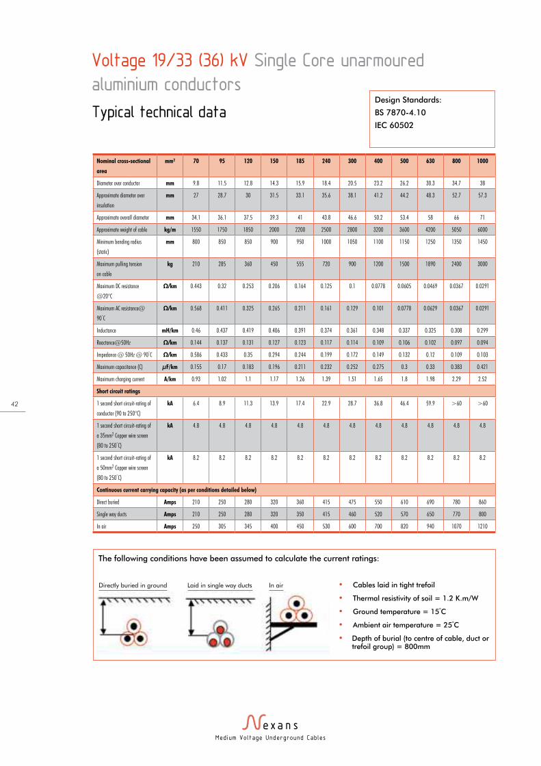
Med ium Vo l tage Underground Cab les
42
Voltage 19/33 (36) kV Single Core unarmoured
aluminium conductors
Typical technical data
Nominal cross-sectional
area
mm² 70 95 120 150 185 240 300 400 500 630 800 1000
Diameter over conductor mm 9.8 11.5 12.8 14.3 15.9 18.4 20.5 23.2 26.2 30.3 34.7 38
Approximate diameter over
insulation
mm 27 28.7 30 31.5 33.1 35.6 38.1 41.2 44.2 48.3 52.7 57.3
Approximate overall diameter mm 34.1 36.1 37.5 39.3 41 43.8 46.6 50.2 53.4 58 66 71
Approximate weight of cable kg/m 1550 1750 1850 2000 2200 2500 2800 3200 3600 4200 5050 6000
Minimum bending radius
(static)
mm 800 850 850 900 950 1000 1050 1100 1150 1250 1350 1450
Maximum pulling tension
on cable
kg 210 285 360 450 555 720 900 1200 1500 1890 2400 3000
Maximum DC resistance
@20°C
Ω/km 0.443 0.32 0.253 0.206 0.164 0.125 0.1 0.0778 0.0605 0.0469 0.0367 0.0291
Maximum AC resistance@
90°C
Ω/km 0.568 0.411 0.325 0.265 0.211 0.161 0.129 0.101 0.0778 0.0629 0.0367 0.0291
Inductance mH/km 0.46 0.437 0.419 0.406 0.391 0.374 0.361 0.348 0.337 0.325 0.308 0.299
Reactance@50Hz Ω/km 0.144 0.137 0.131 0.127 0.123 0.117 0.114 0.109 0.106 0.102 0.097 0.094
Impedance @ 50Hz @ 90°C Ω/km 0.586 0.433 0.35 0.294 0.244 0.199 0.172 0.149 0.132 0.12 0.109 0.103
Maximum capacitance (C) µF/km 0.155 0.17 0.183 0.196 0.211 0.232 0.252 0.275 0.3 0.33 0.383 0.421
Maximum charging current A/km 0.93 1.02 1.1 1.17 1.26 1.39 1.51 1.65 1.8 1.98 2.29 2.52
Short circuit ratings
1 second short circuit-rating of
conductor (90 to 250°C)
kA 6.4 8.9 11.3 13.9 17.4 22.9 28.7 36.8 46.4 59.9 >60 >60
1 second short circuit-rating of
a 35mm2 Copper wire screen
(80 to 250°C)
kA 4.8 4.8 4.8 4.8 4.8 4.8 4.8 4.8 4.8 4.8 4.8 4.8
1 second short circuit-rating of
a 50mm2 Copper wire screen
(80 to 250°C)
kA 8.2 8.2 8.2 8.2 8.2 8.2 8.2 8.2 8.2 8.2 8.2 8.2
Continuous current carrying capacity (as per conditions detailed below)
Direct buried Amps 210 250 280 320 360 415 475 550 610 690 780 860
Single way ducts Amps 210 250 280 320 350 415 460 520 570 650 770 800
In air Amps 250 305 345 400 450 530 600 700 820 940 1070 1210
Design Standards:
BS 7870-4.10
IEC 60502
The following conditions have been assumed to calculate the current ratings:
• Cables laid in tight trefoil
• Thermal resistivity of soil = 1.2 K.m/W
• Ground temperature = 15°C
• Ambient air temperature = 25°C
• Depth of burial (to centre of cable, duct or trefoil group) = 800mm
Directly buried in ground Laid in single way ducts In air

Med ium Vo l tage Underground Cab les
43
Voltage 19/33 (36) kV Single Core armoured copper
conductors
Typical technical data
Nominal cross-sectional
area
mm² 70 95 120 150 185 240 300 400 500 630 800 1000
Diameter over conductor mm 9.8 11.5 12.8 14.3 15.9 18.4 20.5 23.2 26.2 30.3 34.7 38
Approximate diameter over
insulation
mm 27 28.7 30 31.5 33.1 35.6 38.1 41.2 44.2 48.3 52.7 57.3
Approximate overall diameter mm 43 45 47 50 51 54 57 60 63 67 74 79
Approximate weight of cable kg/m 2450 2800 3150 3650 4150 4800 5600 6600 7800 9400 11550 13850
Minimum bending radius
(static)
mm 900 900 950 1000 1050 1100 1150 1200 1300 1350 1500 1600
Maximum pulling tension
on cable
kg 350 475 600 750 925 1200 1500 2000 2500 3150 4000 5000
Maximum DC resistance
@20°C
Ω/km 0.2680 0.1930 0.1530 0.1240 0.0991 0.0754 0.0601 0.0470 0.0366 0.0283 0.0221 0.0176
Maximum AC resistance@
90°C
Ω/km 0.3420 0.2470 0.1960 0.1590 0.1270 0.0974 0.0783 0.0622 0.0496 0.0399 0.0331 0.0284
Inductance mH/km 0.482 0.458 0.439 0.431 0.420 0.400 0.383 0.369 0.357 0.344 0.327 0.317
Reactance@50Hz Ω/km 0.152 0.144 0.138 0.135 0.132 0.126 0.120 0.116 0.112 0.108 0.103 0.099
Impedance @ 50Hz @ 90°C Ω/km .379.374 0.286 0.239 0.209 0.183 0.159 0.144 0.132 0.123 0.115 0.108 0.103
Maximum capacitance (C) µF/km 0.155 0.17 0.183 0.196 0.207 0.228 0.252 0.275 0.3 0.33 0.383 0.421
Maximum charging current A/km 0.93 1.02 1.1 1.17 1.24 1.36 1.51 1.65 1.8 1.98 2.29 2.52
Short circuit ratings
1 second short circuit-rating of
conductor (90 to 250°C)
kA 9.7 13.5 17.1 21 26.3 34.6 43.4 55.6 >60 >60 >60 >60
1 second short circuit-rating of
metallic screen (80 to 200°C)
kA 9.7 13.3 13.8 18.3 19.1 20 21.2 22.5 24.2 25.8 28.7 30.8
Continuous Current Carrying Capacity (as per conditions detailed below)
Direct buried Amps 270 320 360 410 455 520 580 650 710 760 810 860
Single way ducts Amps 260 300 340 370 400 450 490 530 570 610 670 700
In air Amps 320 380 440 490 560 650 730 830 940 1050 1160 1260
Design Standards:
BS 6622
BS 7835
The following conditions have been assumed to calculate the current ratings:
• Cables laid in tight trefoil
• Thermal resistivity of soil = 1.2 K.m/W
• Ground temperature = 15°C
• Ambient air temperature = 25°C
• Depth of burial (to centre of cable, duct or trefoil group) = 800mm
Directly buried in ground Laid in single way ducts In air

Med ium Vo l tage Underground Cab les
44
Voltage 19/33 (36) kV Three Core armoured copper
conductors
Typical technical dataDesign Standards:
BS 6622
BS 7835
Nominal cross-sectional area mm² 3x70 3x95 3x120 3x150 3x185 3x240 3x300 3x400
Diameter over conductor mm 9.8 11.5 12.8 14.3 15.9 18.4 20.5 23.2
Approximate diameter over insulation mm 27 28.7 30 31.5 33.1 35.6 38.1 41.2
Approximate overall diameter mm 75 79 83 86 89 95 101 108
Approximate weight of cable kg/m 6400 7550 8550 9600 11000 13200 15600 18650
Minimum bending radius (static) mm 1150 1200 1250 1300 1350 1450 1550 1650
Maximum pulling tension on cable kg 1050 1425 1800 2250 2775 3600 4500 5000
Maximum DC resistance @20°C Ω/km 0.2680 0.1930 0.1530 0.1240 0.0991 0.0754 0.0601 0.0470
Maximum AC resistance@ 90°C Ω/km 0.3420 0.2470 0.1960 0.1590 0.1280 0.0978 0.0788 0.0629
Inductance mH/km 0.427 0.405 0.387 0.375 0.365 0.348 0.333 0.321
Reactance@50Hz Ω/km 0.134 0.127 0.122 0.118 0.115 0.109 0.105 0.101
Impedance @ 50Hz @ 90°C Ω/km 0.367 0.277 0.23 0.198 0.172 0.147 0.131 0.119
Maximum capacitance (C) µF/km 0.155 0.17 0.183 0.196 0.207 0.228 0.252 0.275
Maximum charging current A/km 0.93 1.02 1.1 1.17 1.24 1.36 1.51 1.65
Short circuit ratings
1 second short circuit-rating of conductor (90 to 250°C) kA 9.7 13.5 17.1 21 26.3 34.6 43.4 55.6
1 second short circuit-rating of metallic screen (80 to 200°C) kA 4.6 4.6 5 5 5.3 5.7 6.1 6.5
Continuous current carrying capacity (as per conditions detailed below)
Direct buried Amps 255 295 335 375 420 490 550 610
Single way ducts Amps 230 260 305 335 380 435 490 550
In air Amps 290 330 390 440 500 580 660 730
The following conditions have been assumed to calculate the current ratings:
• Thermal resistivity of soil = 1.2 K.m/W
• Ground temperature = 15°C
• Ambient air temperature = 25°C
• Depth of burial (to centre of cable, duct or trefoil group) = 800mm
Directly buried in ground Laid in single way ducts In air

Med ium Vo l tage Underground Cab les
45
Notes
Med ium Vo l tage Underground Cab les
46
Notes
Med ium Vo l tage Underground Cab les
47
Notes
PHLB
1009 E
ditio
n 03/2
009
Nexans Energy Networks
Nexans House, Chesney Wold, Bleak Hall, Milton Keynes MK6 1LA
Tel: 01908 250840 Fax: 01908 250841 Email: [email protected]
www.nexans.co.uk
With energy as the basis of its
development, Nexans, the worldwide
leader in the cable industry, offers an
extensive range of cables and cabling
systems, The Group is a global player
in the infrastructure, industry, building
and Local Area Network markets.
Nexans addresses a series of market
segments from energy, transport and
telecom networks to shipbuilding, oil
and gas, nuclear power, automotive,
electronics, aeronautics, handling and
automation. With an industrial presence
in 39 countries and commercial activities
worldwide, Nexans employs 23,500
people and had sales in 2008 of
6.8 billion Euros.