6 global positioning system (gps) survey guidelines documents...global positioning system (gps)...
TRANSCRIPT
GLOBAL POSITIONING SYSTEM (GPS) SURVEY GUIDELINES - FEBRUARY 2010
NCDOT Location and Surveys Manual 6-1
6 Global Positioning System (GPS) Survey Guidelines Survey Guidelines describe recommended methods and procedures needed to attain a desired
survey accuracy standard. The guidelines in this section are based upon several sources of information as well as practical experience. The following sources were utilized in preparing these guidelines:
• “Geometric Geodetic Accuracy Standards and Specifications for using GPS Relative
Positioning Techniques” by the Federal Geodetic Control Committee dated August 1, 1989 • NOAA Technical Memorandum NOS NGS-58 titled “Guidelines for establishing GPS-
derived Ellipsoid Heights” dated November 1997. • CalTrans Survey Manual Chapter 6 titled “Global Positioning System (GPS) Survey
Specifications” dated September 2006.
Location and Surveys GPS Survey Guidelines are to be used for all NCDOT-involved transportation improvement projects, including special-funded projects.
Global Positioning System surveying is a continuously evolving technology. As GPS hardware
and processing software are improved, new guidelines will be developed and existing guidelines will be changed. The guidelines described in this section are not intended to discourage the development of new GPS procedures and techniques.
Note: Newly developed GPS procedures and techniques, which do not conform to the
guidelines in this section, may be employed for production surveys if approved by the Location and Surveys Unit. Newly developed procedures shall be submitted to the Location and Surveys Unit for review and distribution.
Note: The specifications in Section 6A, “Post Processed GPS Survey Specifications” are
separate and distinct from the specifications in Section 6B, “Real-Time Kinematic (RTK) GPS Survey Specifications.”
GLOBAL POSITIONING SYSTEM (GPS) SURVEY GUIDELINES - FEBRUARY 2010
NCDOT Location and Surveys Manual 6-2
6A Post Processed GPS Survey Specifications
6A.1 Methods 6A.1-1 Static GPS Surveys Static GPS survey procedures allow various systematic errors to be resolved when high
accuracy positioning is required. Static procedures are used to measure baselines between stationary GPS receivers by recording data over an extended period of time during which the satellite geometry changes. This procedure should be applied for all occupations requiring horizontal accuracy of greater than 1:100,000.
6A.1-2 Fast-static GPS Surveys Fast-static GPS surveys are similar to static GPS surveys, but with shorter observation
periods. Fast-static GPS survey procedures require more advanced equipment and data reduction techniques than static GPS methods. Typically, the fast-static GPS method should not be used for requiring horizontal accuracy greater than 1: 100,000.
6A.1-3 Kinematic GPS Surveys Kinematic GPS surveys make use of two or more GPS receivers. At least one receiver is
set up over a known (reference) point and remains stationary, while another (rover) receiver is moved from point to point. All baselines are measured from the reference receiver to the roving receiver. Kinematic GPS surveys can be either continuous or stop and go." Stop and go station observation periods are of short duration, typically under two minutes. Kinematic GPS surveys are employed where third-order or lower accuracy standards are applicable.
6A.1-4 OPUS GPS Surveys The NGS On-line Positioning User Service (OPUS) allows users to submit individual
GPS unit data files directly to NGS for automatic processing. Each data file that is submitted is processed with respect to 3 CORS sites. For small standalone projects it is acceptable to use NGS’s Online User Positioning Service (OPUS) in conjunction with other techniques to establish initial control.
GLOBAL POSITIONING SYSTEM (GPS) SURVEY GUIDELINES - FEBRUARY 2010
NCDOT Location and Surveys Manual 6-3
6A.2 Equipment
Post processed GPS surveying equipment generally consists of two major components: the receiver and the antenna.
6A. 2-1 Receiver Requirements
First-order, second-order, and third-order post processed GPS surveys require GPS receivers that are capable of recording data. When performing specific types of GPS surveys (i.e. static, fast-static, and kinematic), receivers and software shall be suitable for the specific survey as specified by the manufacturer. Dual frequency receivers shall be used for observing baselines over 9 miles in length. During periods of intense solar activity, dual frequency receivers shall be used for observing baselines over 6 miles in length.
6A.2-2 Antennas
Whenever feasible, all antennas used for a project should be identical. For vertical control surveys, identical antennas shall be used unless software is available to accommodate the use of different antennas. For first-order and second-order horizontal surveys, antennas with a ground plane attached shall be used, and the antennas shall be mounted on a tripod or a stable supporting tower. When tripods or towers are used, optical plummets or collimators are required to ensure accurate centering over marks. Fixed height tripods are required for third-order or better vertical surveys. The use of range poles and/or stake-out poles to support GPS antennas should only be employed for third-order horizontal and general-order surveys.
6A.2-3 Miscellaneous Equipment Requirements
All equipment must be properly maintained and regularly checked for accuracy. Errors due to poorly maintained equipment must be eliminated to ensure valid survey results. Level vials, optical plummets, and collimators shall be calibrated at the beginning and end of each GPS survey. If the duration of the survey exceeds a week, these calibrations shall be repeated weekly for the duration of the survey.
GLOBAL POSITIONING SYSTEM (GPS) SURVEY GUIDELINES - FEBRUARY 2010
NCDOT Location and Surveys Manual 6-4
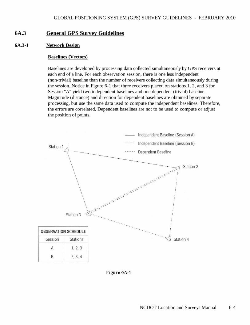
6A.3 General GPS Survey Guidelines 6A.3-1 Network Design Baselines (Vectors) Baselines are developed by processing data collected simultaneously by GPS receivers at
each end of a line. For each observation session, there is one less independent (non-trivial) baseline than the number of receivers collecting data simultaneously during the session. Notice in Figure 6-1 that three receivers placed on stations 1, 2, and 3 for Session "A" yield two independent baselines and one dependent (trivial) baseline. Magnitude (distance) and direction for dependent baselines are obtained by separate processing, but use the same data used to compute the independent baselines. Therefore, the errors are correlated. Dependent baselines are not to be used to compute or adjust the position of points.
GLOBAL POSITIONING SYSTEM (GPS) SURVEY GUIDELINES - FEBRUARY 2010
NCDOT Location and Surveys Manual 6-5
Loops A loop is defined as a series of at least three independent, connecting baselines which
start and end at the same station. Each loop must have at least one baseline in common with another loop. Each loop must contain baselines collected from a minimum of two sessions.
Control Networks Networks should only contain closed loops. Each station in a network must be
connected ,with at least two different independent baselines. Avoid connecting stations to a network by multiple baselines to only one other network station. First-order and second-order GPS control networks should consist of a series of interconnecting, closed loop, geometric figures.
Redundancy First-order, second-order, and third-order GPS control networks are designed with
sufficient redundancy to detect and isolate blunders and/or systematic errors. Redundancy of network design is achieved by:
• Connecting each network station with at least two independent baselines • Series of interconnecting, closed loops • Repeat baseline measurements
Refer to table 6A-1 for the maximum number of baselines per loop, the number of
required repeat independent baseline measurements, and least squares network adjustment guidelines.
Any GPS survey that lacks sufficient network or station redundancy to detect
misclosures in an unconstrained (free) least squares network adjustment must be considered a general order GPS survey.
GLOBAL POSITIONING SYSTEM (GPS) SURVEY GUIDELINES - FEBRUARY 2010
NCDOT Location and Surveys Manual 6-6
Reference Stations The reference (controlling) stations for a GPS survey must meet the following
requirements:
• Same or higher order of accuracy as that intended for the project • All included in, or adjusted to, the High Accuracy Reference Network (HARN) with
coordinate values that are current and meet reference network accuracy standards • The Horizontal Datum for the HARN network is NAD 1983/NSRS 2007 and the
Vertical Datum is NAVD88. Although these will be the preferred datums, it may be necessary to use existing monumentation with an earlier datum in order to keep consistency with previously controlled Projects or with Standalone Projects such as Bridge jobs. It will be the responsibility of the Location and Surveys Unit to determine the datum(s) to be utilized on a case by case basis.
• Evenly spaced throughout the survey project and in a manner that no project station is outside the area encompassed by the exterior reference stations
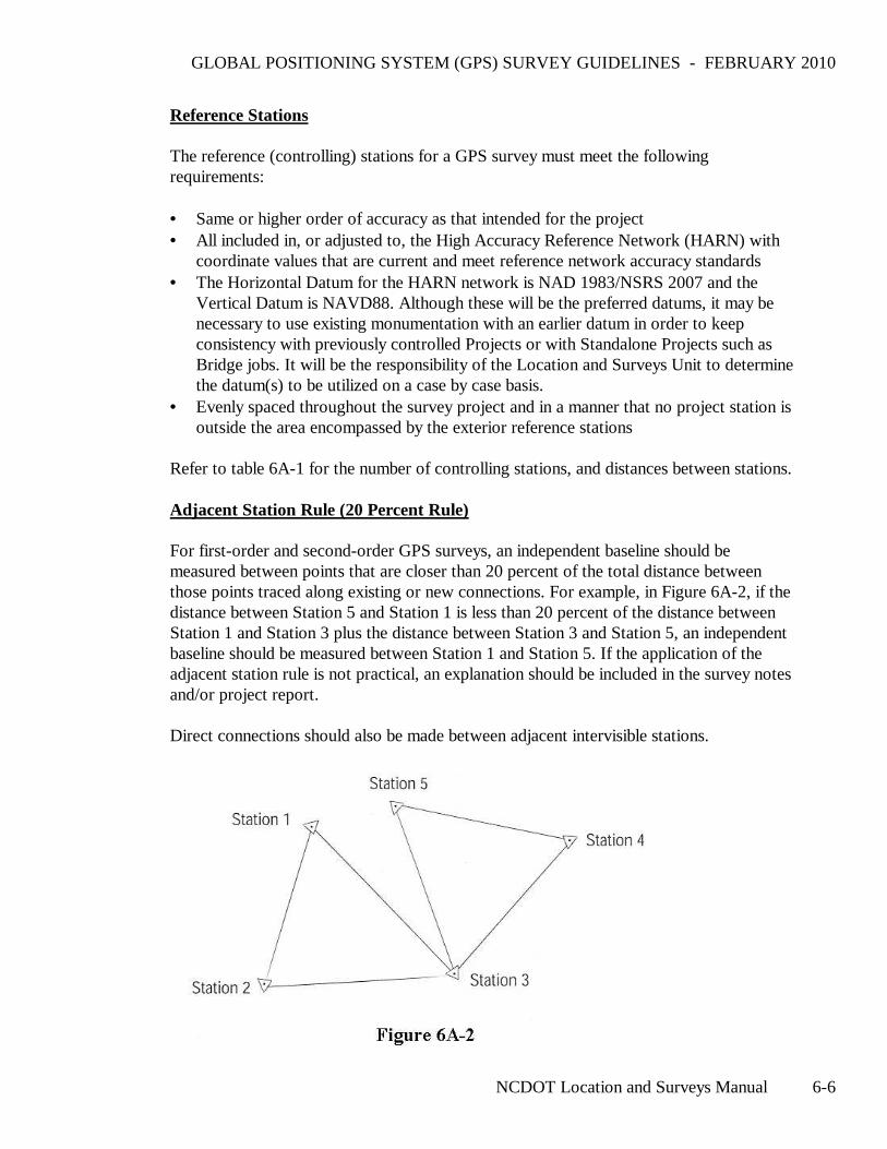
Refer to table 6A-1 for the number of controlling stations, and distances between stations. Adjacent Station Rule (20 Percent Rule) For first-order and second-order GPS surveys, an independent baseline should be
measured between points that are closer than 20 percent of the total distance between those points traced along existing or new connections. For example, in Figure 6A-2, if the distance between Station 5 and Station 1 is less than 20 percent of the distance between Station 1 and Station 3 plus the distance between Station 3 and Station 5, an independent baseline should be measured between Station 1 and Station 5. If the application of the adjacent station rule is not practical, an explanation should be included in the survey notes and/or project report.
Direct connections should also be made between adjacent intervisible stations.
GLOBAL POSITIONING SYSTEM (GPS) SURVEY GUIDELINES - FEBRUARY 2010
NCDOT Location and Surveys Manual 6-7
6A.3-2 Satellite Geometry Satellite geometry factors which must be considered when planning a GPS survey are:
• Number of satellites available • Minimum elevation angle for satellites (elevation mask) • Obstructions limiting satellite visibility • Position Dilution of Precision (PDOP)
Refer to table 6A-1 for specific requirements. 6A.3-3 Field Procedures Reconnaissance Proper field reconnaissance is essential to the execution of efficient, effective GPS
surveys. Reconnaissance should include:
• Station setting or recovery • Checks for obstructions and multipath potential • Preparation of station descriptions (monument description, to-reach descriptions for
azimuth pairs, etc.) • Development of a realistic observation schedule
Station Site Selection The most important factor for determining GPS station location is the project's
requirements (needs). After project requirements, consideration must be given to the following limitations of GPS:
• Stations should be situated in locations that are relatively free from horizontal obstruc-
tions. In general, a clear view of the sky is required. Satellite signals do not penetrate metal, buildings, or trees and are susceptible to signal delay errors when passing through leaves, glass, plastic and other materials.
• Locations near strong radio transmissions should be avoided because radio frequency
transmitters, including cellular phone equipment, may disturb satellite signal reception. • Avoid locating stations near large flat surfaces such as buildings, large signs, fences,
etc., as satellite signals may be reflected off these surfaces causing multipath errors. With proper planning, some obstructions near a GPS station may be acceptable. For example, station occupation times may be extended to compensate for obstructions.
GLOBAL POSITIONING SYSTEM (GPS) SURVEY GUIDELINES - FEBRUARY 2010
NCDOT Location and Surveys Manual 6-8
Weather Conditions Generally weather conditions do not affect GPS survey procedures with the following
exceptions:
• GPS observations should never be conducted during electrical storms. • Significant changes in weather or unusual weather conditions should be noted in the
observation log (field notes). Horizontal GPS surveys should generally be avoided during periods of significant weather changes. Vertical GPS surveys should not be attempted during these periods.
Antenna Height Measurements Blunders in antenna height measurements are the most common source of error in GPS
surveys because all GPS surveys are three dimensional whether the vertical component will be used or not. Antenna height measurements determine the height from the survey monument mark to the phase center of the GPS antenna. With the exception of fixed-height tripods and permanently mounted GPS antennas, independent antenna heights should be measured in both feet and meters at the beginning and end of each observation session. A height hook or slant rod shall be used to make these measurements. All antenna height measurements should be recorded and entered in the receiver data file. Antenna height measurements in both feet and meters should check to within +/- 3 mm.
When a station is occupied during two or more observation sessions back to back, the
antenna/tripod should be broken down, reset, and replumbed between sessions. When adjustable antenna staffs are used (e.g., kinematic surveys), they must be adjusted
so that the body of the person holding the staff does not act as an obstruction. The antenna height for staffs in extended positions must be checked continually throughout each day.
When fixed-height tripods are used, verify the height of the tripod and components
(antenna) at the beginning of the project.
GLOBAL POSITIONING SYSTEM (GPS) SURVEY GUIDELINES - FEBRUARY 2010
NCDOT Location and Surveys Manual 6-9
Documentation The final GPS survey project report should include the following information:
♦ The existing control monuments used in the transfer ♦ An explanation of how adjustments were performed ♦ A printout of the Initial Analysis Worksheet as produced from the most current
version of GPSPrj.XLT ♦ Project Sketch Map ♦ A listing of map projection transformation ♦ A listing of loop closures ♦ Location sketches and descriptions of all azimuth control pairs on control data
sheets to include their X,Y,Z coordinate values, scale factor and GEOID separation ♦ GPS vector map as required by North Carolina Administrative Code, Title 21,
Chapter 56, Section .1607 ♦ An electronic MS-Excel spreadsheet file with all Project data utilizing the most
current version of GPSPrj.XLT. 6A.3-4 Office Procedures General For Primary GPS Control surveys, raw GPS observation (tracking) data must be
collected and post processed for results and analysis. Post processing and analysis are required for first-order and second-order GPS surveys. The primary post processed results that are analyzed are:
♦ Baseline processing results ♦ Loop closures ♦ Repeat baseline differences ♦ Results from least squares network adjustments
Post processing software must be capable of producing relative-position coordinates and corresponding statistics which can be used in a three-dimensional least squares network adjustment. This software should also allow analysis of loop closures and repeat baseline observations.
GLOBAL POSITIONING SYSTEM (GPS) SURVEY GUIDELINES - FEBRUARY 2010
NCDOT Location and Surveys Manual 6-10
Loop Closure and Repeat Baseline Analysis Loop closures and differences in repeat baseline measurements are computed to check
for blunders and to obtain initial estimates of the internal consistency of the GPS network. Tabulate and include loop closures and the differences in repeat baseline measurements in the project documentation. Failure of a baseline in a loop closure does not automatically mean that the baseline in question should be rejected but is an indication that a portion of the network requires additional analysis.
Least Squares Network Adjustment An unconstrained (free) adjustment is performed, after blunders are removed from the
network, to verify the baseline measurements of the network. After a satisfactory standard deviation of unit weight is achieved using realistic a priori error estimates, a constrained adjustment is performed.
The constrained network adjustment fixes the coordinates of the known control points,
thereby adjusting the network to the datum of the control points. A consistent control reference network (datum) must be used for the constrained adjustment.
GLOBAL POSITIONING SYSTEM (GPS) SURVEY GUIDELINES - FEBRUARY 2010
NCDOT Location and Surveys Manual 6-11
6A-4 Primary GPS Control Surveys 6A.4-1 Applications Primary GPS Control Surveys are utilized for the following typical Location and
Surveys survey operations: Supplemental control for engineering and construction surveys Project Controls for Baselines Photogrammetry control 6A.4-2 Guidelines Methods
♦ Static ♦ Fast-static
Table 6A-1 lists the guidelines for Primary GPS Control using Static, Fast-static GPS
procedures.
GLOBAL POSITIONING SYSTEM (GPS) SURVEY GUIDELINES - FEBRUARY 2010
NCDOT Location and Surveys Manual 6-12
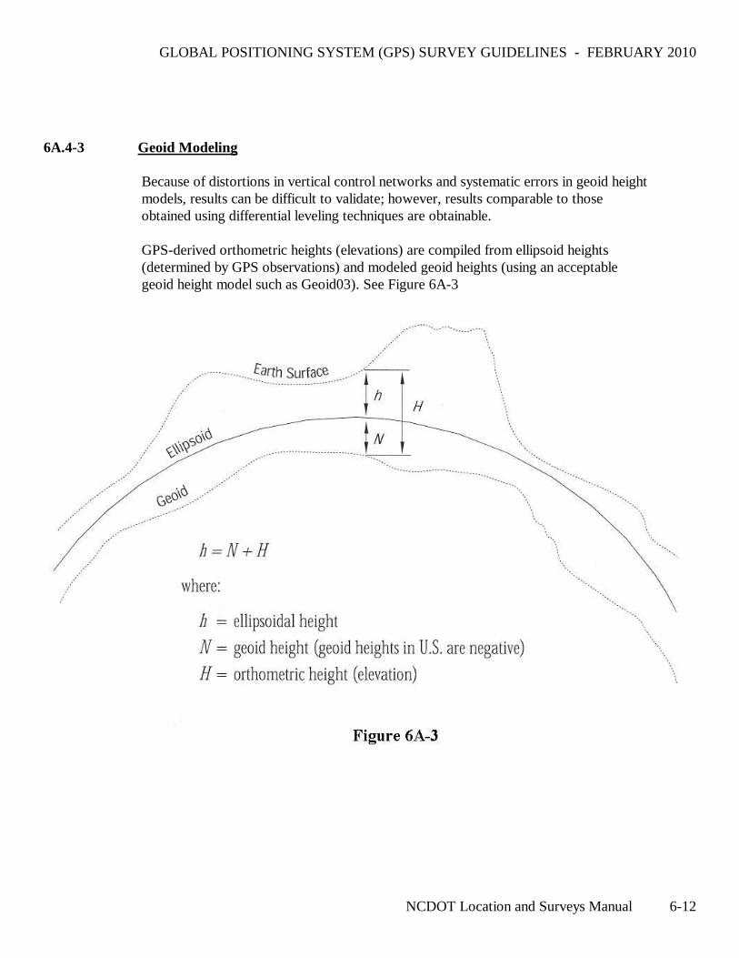
6A.4-3 Geoid Modeling Because of distortions in vertical control networks and systematic errors in geoid height
models, results can be difficult to validate; however, results comparable to those obtained using differential leveling techniques are obtainable.
GPS-derived orthometric heights (elevations) are compiled from ellipsoid heights
(determined by GPS observations) and modeled geoid heights (using an acceptable geoid height model such as Geoid03). See Figure 6A-3
GLOBAL POSITIONING SYSTEM (GPS) SURVEY GUIDELINES - FEBRUARY 2010
NCDOT Location and Surveys Manual 6-13
Table 6A-1 GPS Control Survey Guidelines
Specification Static Fast-Static
General
Minimum number of reference stations for the project 3 HARN or CORS 3 HARN or CORS
Location of horizontal control stations (relative to center of project); minimum number of “quadrants,” not less than
3 3
Minimum number of vertical control stations (benchmarks) for the project
4 4
Location of vertical control stations (relative to center of project); minimum number of “quadrants,” not less than
4 4
Maximum distance between the survey project boundary and network control stations
30 miles (50 km) 30 miles (50 km)
Minimum percentage of all baselines contained in a loop 100% 100%
Direct connection between survey points which are less than 20 percent of the distance between those points traced along existing or new connections (adjacent station rule) Yes Yes
Minimum percentage of repeat independent baseline measurements 5% 5%
Minimum number of independent occupations per station 100% (2 times) 10% (3 or more times)
100% (2 times) 10% (3 or more times)
Direct connection between intervisible azimuth pairs Yes Yes
Field
Dual frequency GPS receivers required Yes Yes
Maximum PDOP during station occupation 6 6
Minimum observation time on station 1-6 km 30 minutes 15 minutes
Minimum observation time on station 6-10 km 30 minutes 20 minutes
Minimum observation time on station 10-15 km 30 minutes 30 minutes
Minimum observation time on station >15 km 1 hour 1 hour
* Relative to the existing vertical control
GLOBAL POSITIONING SYSTEM (GPS) SURVEY GUIDELINES - FEBRUARY 2010
NCDOT Location and Surveys Manual 6-14
Table 6A-1, Continued
Specification Static Fast-Static
Field
Minimum number of satellites observed simultaneously at all stations
5 5
Maximum epoch interval for data sampling 15 seconds 5 seconds
Minimum time between repeat station observations 20 minutes 20 minutes
Minimum satellite mask angle above the horizon 10 degrees 10 degrees
Fixed height antenna tripod required Yes Yes
Specification Static Fast-Static
Office
Fixed integer solution required for all baselines Yes Yes
Ephemeris Precise Precise
Initial position: maximum 3-d position error for the initial station in any baseline solution.
33 feet (10 m) 33 feet (10 m)
Loop closure analysis, maximum number of baselines per loop
8 8
Maximum loop length 47 miles (75 km) 47 miles (75 km)
Maximum misclosure per loop, in terms of loop length 10 ppm 10 ppm
Maximum misclosure per loop in any one component (x,y,z) not to exceed
0.17 feet (0.050 m) 0.17 feet (0.050 m)
Repeat baseline length not to exceed 6 miles (10 km) 6 miles (10 km)
Repeat baseline difference in any one component (x,y,z) not to exceed
10 ppm 10 ppm
Maximum length misclosure allowed for a baseline in a properly-weighted, least squares network adjustment
10 ppm 10 ppm
Maximum allowable residual in any one component (x,y,z) in a properly-weighted, least squares network adjustment
0.10 feet (0.030 m) 0.10 feet (0.030 m)
Maximum ellipsoid height difference for repeat baselines 0.07 feet (0.020 m) 0.16 feet (0.020 m)
Apply high resolution Geoid modey Yes Yes
Maximum RMS values of processed baselines (2σ) 0.05 feet (0.015 m) typically <0.03 feet
(0.010 m)
0.05 feet (0.015 m) typically <0.03 feet
(0.010 m)
GLOBAL POSITIONING SYSTEM (GPS) SURVEY GUIDELINES - FEBRUARY 2010
NCDOT Location and Surveys Manual 6-15
6B Real Time Kinematic (RTK) GPS Survey Specifications
6B.1 Method
6B.1-1 Conventional (Single Base Station) RTK GPS Surveys
Conventional RTK GPS surveys are kinematic GPS surveys (Section 6A.1-3) that are performed with a data transfer link between a reference GPS unit (base station) and rover unit(s). The field survey is conducted like a kinematic survey, except measurement data from the base station is transmitted to the rover unit(s), enabling the rover unit(s) to compute position in real time. The derived solution is a product of a single baseline vector from the base station to the rover unit(s).
6B.1-2 Real Time Network RTK GPS Surveys (VRS)
Real-time surveys with North Carolina’s Network RTK system are similar in principle to conventional RTK surveys. Instead of a single base station, however, the system utilizes the Continuously Operating Reference Stations (CORS) in the State. The CORS send measurement data to the central computer system, which processes the data and monitors the integrity of the CORS network. This also allows for modeling of GPS errors over the entire network area. The Rover unit contacts the central computer system through a cellular link and starts receiving a unique correction based upon its location in the network.
6B.2 Equipment
A conventional RTK system consists of a base station, one or more rover units, and a data transfer link between the base station and the rover unit(s).
6B.2-1 Base Station Requirements
A base station is comprised of a GPS receiver, an antenna, and a tripod. The GPS receiver and the antenna shall be suitable for the specific survey as determined from the manufacturer’s specifications. Tripod requirements are specified in Section 6B.3-3.
6B.2-2 Rover Unit Requirements
The rover unit is comprised of a GPS receiver, an antenna, and a rover pole. The GPS receiver and the antenna shall be suitable for the specific survey as determined from the manufacturer’s specifications.
A rover antenna shall be identical (not including a ground plane, if used at the base station) to the base station antenna unless the firmware/software is able to accommodate antenna modeling of different antenna types.
Rover pole requirements are specified in Section 6B.3-3.
GLOBAL POSITIONING SYSTEM (GPS) SURVEY GUIDELINES - FEBRUARY 2010
NCDOT Location and Surveys Manual 6-16
6B.2-3 Data Transfer Link
The data transfer link can be either a UHF/VHF radio link or a cellular telephone link. The data transfer link shall be capable of sending the base station’s positional data, carrier phase information, and pseudo-range information from the base station to the rover unit. This information shall be sufficient to correct the rover unit’s position to an accuracy that is appropriate for the type of survey being conducted.
If the data transfer link utilizes a UHF/VHF radio link with an output of greater than 1 watt, a Federal Communications Commission (FCC) license is required.
All FCC rules and regulations shall be adhered to when performing an RTK survey.
Voice users have primary authorization on the portion of the radio spectrum utilized for RTK surveying. Data transmission is authorized on a secondary and non-interfering basis to voice use.
Failure to comply with FCC regulations subjects the operator, and their employer, to fines, seizure of their surveying equipment, civil liability, and/or criminal prosecution. Failure to comply also jeopardizes the future use of RTK/GPS surveying by or for NCDOT.
6B.2-4 Miscellaneous Equipment Requirements
The RTK equipment shall be suitable for the work being done.
All RTK equipment shall be properly maintained and checked for accuracy. The accuracy checks shall be conducted before each survey or at a minimum of once a month to ensure valid survey results.
6B.3 General RTK Survey Specifications
In a conventional RTK survey “radial” shots are observed from a fixed base station to a rover unit. A delta X, delta Y, and delta Z are produced from the base station to the rover unit on the WGS84 datum. From these values, coordinates of the points occupied by the rover unit are produced.
6B.3-1 RTK Survey Design
RTK survey design differs from static and fast static GPS survey design. With static and fast static GPS surveys, a network design method is used. See Section 6A.3-1, “Network Design,” for more details on GPS network design. The following criteria shall be used for RTK survey design:
GLOBAL POSITIONING SYSTEM (GPS) SURVEY GUIDELINES - FEBRUARY 2010
NCDOT Location and Surveys Manual 6-17
• The project area shall be “surrounded” and enclosed with RTK control stations. (See the definition of RTK control station below.)
• If the RTK control station is used for horizontal control, the RTK control station shall have horizontal coordinates that are on the same datum and epoch as the datum and epoch required for the project.
• If the RTK control station is used for vertical control, the RTK control station shall have a height that is on the same datum as the datum required for the project.
• All RTK control stations shall be included in a GPS site calibration. (See the end of this section for the definition of a GPS site calibration.)
• If the RTK equipment does not support the use of a GPS site calibration, the RTK control stations shall be used as check shots.
• For third order RTK surveys, each new station shall be occupied twice. The second occupation of a new station shall use a different base station location. If the new station is being elevated by RTK methods, the second occupation of the new station shall have a minimum of 3 different satellites in the satellite constellation. This is generally achieved by observing the second occupation at a time of day that is either 4 hours before or 4 hours after the time of day of the first occupation.
• Establish the new stations in areas where obstructions, electromagnetic fields, radio transmissions, and a multipath environment are minimized.
• Use the current geoid model when appropriate.
Definition: An RTK control station is a station used to control a survey that utilizes RTK methods. The station shall have either horizontal coordinates, a height, or both. The order of accuracy of the horizontal coordinates and the height shall be at least third-order.
GLOBAL POSITIONING SYSTEM (GPS) SURVEY GUIDELINES - FEBRUARY 2010
NCDOT Location and Surveys Manual 6-18
Definition: A GPS site calibration establishes a relationship between the observed WGS84 coordinates and the known grid coordinates. This relationship is characterized by a translation, rotation, and scale factor for the horizontal coordinates and by an inclined plane for the heights. By applying a GPS site calibration to newly observed stations, local variations in a mapping projection are reduced and more accurate coordinates are produced from the RTK survey.
Note: A GPS site calibration can be produced from RTK observations, an “office calibration,” or from a combination of both. If the RTK control stations were established by static or fast static GPS techniques, then an office calibration may be used.
The procedures for an office calibration are:
• Do a minimally constrained adjustment before normalization holding only one WGS84 latitude, longitude, and ellipsoid height fixed.
• The epoch of the fixed values shall correspond to the epoch of the final coordinates of the RTK survey.
• Associate the results of this minimally constrained adjustment with the final grid coordinates in a site calibration.
6B.3-2 Satellite Geometry
Satellite geometry affects both the horizontal coordinates and the heights in GPS/RTK surveys. The satellite geometry factors to be considered for RTK surveys are:
• Number of common satellites available at the base station and at the rover unit.
• Minimum elevation angle for the satellites (elevation mask).
• Positional Dilution of Precision (PDOP) or Geometric Dilution of Precision (GDOP).
• Vertical Dilution of Precision (VDOP).
Refer to tables 6B-1 and 6B-2 for specific requirements.
GLOBAL POSITIONING SYSTEM (GPS) SURVEY GUIDELINES - FEBRUARY 2010
NCDOT Location and Surveys Manual 6-19
6B.3-3 RTK Field Procedures
Proper field procedures shall be followed in order to produce an effective RTK survey. For Control RTK Surveys, these procedures shall include:
• It is recommended that the base station occupy an RTK control station with known coordinates for horizontal RTK surveys and known heights for vertical RTK surveys. (Conventional RTK Only)
• A fixed height tripod shall be used for the base station. (Conventional RTK Only)
• A fixed height survey rod or a survey rod with locking pins shall be used for the rover pole. A tripod and a tribrach may also be used. If a fixed height survey rod or a survey rod with locking pins is not used, independent antenna height measurements are required at the beginning and ending of each setup and shall be made in both feet and meters (as a check). The antenna height measurements shall check to within ± 0.01 feet (0.003 m). (Conventional RTK Only)
• A bipod/tripod shall be used with the rover unit’s survey rod.
• The data transfer link shall be established.
• A minimum of five common satellites shall be observed by the base station and the rover unit(s).
• The rover unit(s) shall be initialized before collecting survey data.
• The initialization shall be a valid checked initialization.
• PDOP shall not exceed 6.
• The precision of the measurement data shall have a value less than or equal to 0.03 feet (0.010 m) horizontal and 0.03 feet (0.010 m) vertical for each observed station.
• A check shot shall be observed by the rover unit(s) immediately after the base station is set up and before the base station is taken down.
• The GPS site calibration shall have a maximum horizontal residual of 0.07 feet (0.030 m) for each horizontal RTK control station.
• The GPS site calibration shall have a maximum vertical residual of 0.10 feet (0.030 m) for each vertical RTK control station.
• The new stations shall be occupied for a minimum of 30 epochs of collected data.
• The rover unit(s) shall not be more than 6 miles from the base station.
• The second occupation of a new observed point shall have a maximum difference in coordinates from the first occupation of 0.07 feet (0.020 m). Additional occupations are needed until this requirement is met.
• The second occupation of a new observed point shall have a maximum difference in height from the first occupation of 0.07 feet (0.020 m). Additional occupations are needed until this requirement is met.
GLOBAL POSITIONING SYSTEM (GPS) SURVEY GUIDELINES - FEBRUARY 2010
NCDOT Location and Surveys Manual 6-20
• When setting supplemental control by RTK methods for conventional surveys, it is recommended that the new control points be a minimum of 1000 feet from each other. See Chapter 5, “Accuracy Classifications and Standards,” for minimum accuracy standards that shall be achieved for specific surveys.
• When establishing set-up points for conventional survey methods, set three intervisible points instead of just an “azimuth pair.” (This allows the conventional surveyor a check shot.)
For general-order RTK surveys, these procedures shall include:
• It is recommended that the base station occupy an RTK control station with known coordinates for horizontal RTK surveys and known heights for vertical RTK surveys.
• Fixed height tripods are recommended for the base station. If fixed height tripods are not used, independent antenna height measurements are required at the beginning and ending of each setup and shall be made in both feet and meters (as a check). The antenna height measurements shall check to within ± 0.01 feet (0.003 m).
• A fixed height survey rod or a survey rod with locking pins shall be used for the rover poles. A tripod and tribrach may also be used. If a fixed height survey rod or a survey rod with locking pins is not used, independent antenna height measurements are required at the beginning and ending of each setup and shall be made in both feet and meters (as a check). The antenna height measurements shall check to within ± 0.01 feet (0.003m).
• A bipod/tripod shall be used with the rover unit’s survey rod.
• The data transfer link shall be established.
• A minimum of five common satellites shall be observed by the base station and the rover unit(s).
• The rover unit(s) shall be initialized before collecting survey data.
• The initialization shall be a valid checked initialization.
• PDOP shall not exceed 6.
A check shot shall be observed by the rover unit(s) immediately after the base station is set up and before the base station is taken down. In the case of Network RTK, a check shot shall be observed by the rover unit(s) at the beginning and end of the day’s survey session.
• The GPS site calibration shall have a maximum horizontal residual of 0.07 feet (0.020 m) for each horizontal RTK control station.
• The GPS site calibration shall have a maximum vertical residual of 0.10 feet (0.020 m) for each vertical RTK control station.
• The precision of the measurement data shall have a value less than or equal to 0.03 feet (0.010 m) horizontal and 0.03 feet (0.010 m)vertical for each observed station.
• The rover unit(s) shall not be more than 6 miles (10 km) from the base station.
GLOBAL POSITIONING SYSTEM (GPS) SURVEY GUIDELINES - FEBRUARY 2010
NCDOT Location and Surveys Manual 6-21
6B.3-4 Office Procedures
Proper office procedures must be followed in order to produce valid results. These procedures shall include:
• Review the downloaded field file for correctness and completeness.
• Check the antenna heights for correctness.
• Check the base station coordinates for correctness.
• Analyze all reports.
• Compare the different observations of the same stations to check for discrepancies.
• After all discrepancies are addressed, merge the observations.
• Analyze the final coordinates and the residuals for acceptance.
6B.3-5 General Notes
• At present, RTK surveys shall not be used for pavement elevation surveys or for staking major structures.
• If the data transfer link is unable to be established, the RTK survey may be performed with the intent of post processing the survey data.
• The data transfer link shall not “step on” any voice transmissions.
• If a radio (UHF/VHF) frequency is used for the data transfer link, it shall be checked for voice transmissions before use.
• The data transfer link shall employ a method for ensuring that the signal does not interfere with voice transmissions.
6B.4 Control RTK Surveys
Applications
Control horizontal accuracy is acceptable for the following typical NCDOT RTK operations:
• Supplemental control for engineering surveys and construction surveys
• Photo control
• Construction survey set-up points
• Topographic survey set-up points
• Right of Way surveys
GLOBAL POSITIONING SYSTEM (GPS) SURVEY GUIDELINES - FEBRUARY 2010
NCDOT Location and Surveys Manual 6-22
Control vertical accuracy is acceptable for the following typical NCDOT RTK operations:
• Supplemental control
• Photo control
• Construction survey set-up points
• Topographic survey set-up points
Table 6B-1 lists the specifications for Control accuracy using RTK procedures.
GLOBAL POSITIONING SYSTEM (GPS) SURVEY GUIDELINES - FEBRUARY 2010
NCDOT Location and Surveys Manual 6-23
Table 6B-1 Control RTK Survey Specifications
Specification RTK Survey Network RTK
Field
Geometry of RTK control stations Surround and enclose the RTK project
Surround and enclose the RTK project
Minimum accuracy of RTK control stations Third-order
Minimum number of horizontal RTK control stations for horizontal RTK surveys 4 5
Minimum number of vertical RTK control stations for vertical RTK surveys 5 5
Base station occupies an RTK control station Recommended N/A
Base station uses a fixed height tripod Yes N/A Percent of data collected with a valid checked initialization 100 % 100 %
Maximum PDOP during station observation 6 6 Minimum number of satellites observed simultaneously 5 5
Maximum epoch interval for data sampling 5 seconds 5 seconds
Minimum satellite mask above the horizon 13 degrees 13 degrees
Minimum number of epochs of collected data for each observation 30 30
Horizontal precision of the measurement data for each observation
Less than or equal to 0.03 feet (0.010 m)
Less than or equal to 0.03 feet (0.010 m)
Vertical precision of the measurement data for each observation
Less than or equal to 0.05 feet (0.015 m)
Less than or equal to 0.05 feet (0.015 m)
Continued
GLOBAL POSITIONING SYSTEM (GPS) SURVEY GUIDELINES - FEBRUARY 2010
NCDOT Location and Surveys Manual 6-24
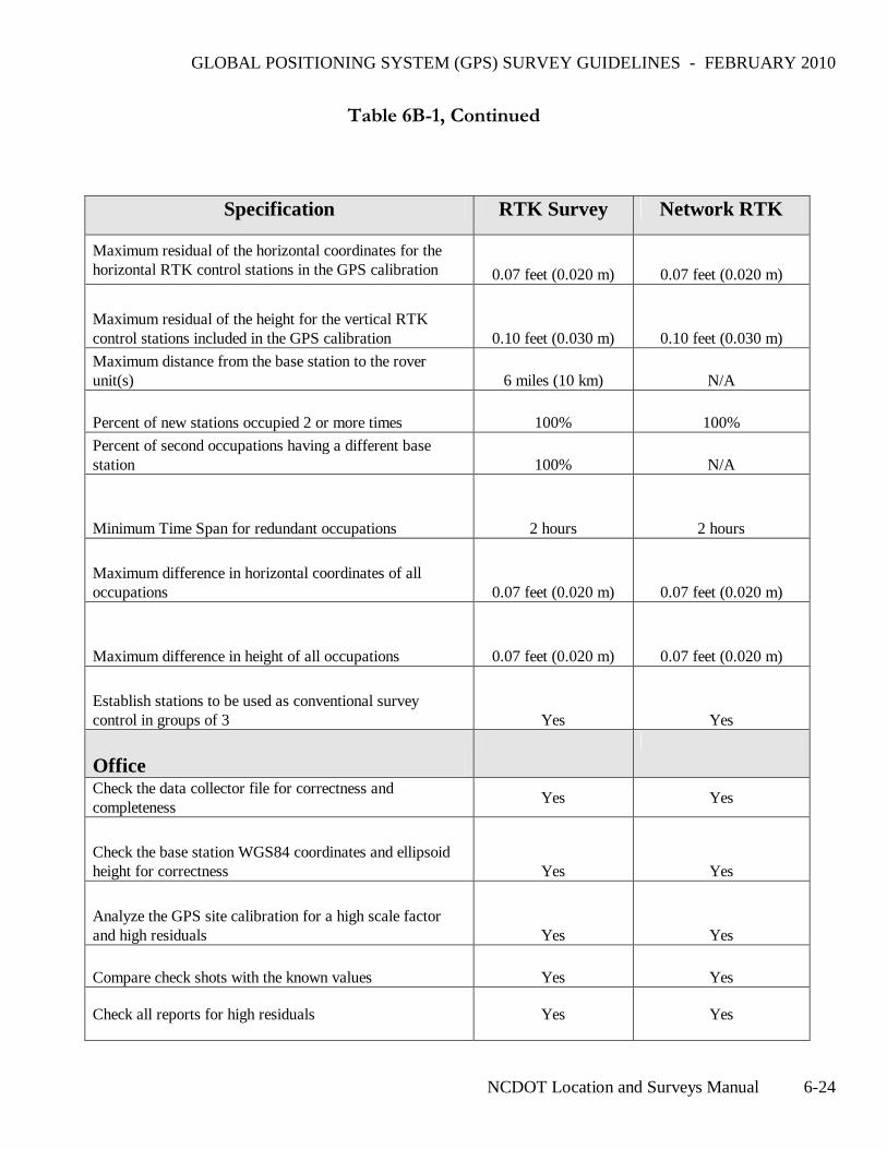
Table 6B-1, Continued
Specification RTK Survey Network RTK
Maximum residual of the horizontal coordinates for the horizontal RTK control stations in the GPS calibration 0.07 feet (0.020 m) 0.07 feet (0.020 m)
Maximum residual of the height for the vertical RTK control stations included in the GPS calibration 0.10 feet (0.030 m) 0.10 feet (0.030 m)
Maximum distance from the base station to the rover unit(s) 6 miles (10 km) N/A
Percent of new stations occupied 2 or more times 100% 100%
Percent of second occupations having a different base station 100% N/A
Minimum Time Span for redundant occupations 2 hours 2 hours
Maximum difference in horizontal coordinates of all occupations 0.07 feet (0.020 m) 0.07 feet (0.020 m)
Maximum difference in height of all occupations 0.07 feet (0.020 m) 0.07 feet (0.020 m)
Establish stations to be used as conventional survey control in groups of 3 Yes Yes
Office
Check the data collector file for correctness and completeness
Yes Yes
Check the base station WGS84 coordinates and ellipsoid height for correctness Yes Yes
Analyze the GPS site calibration for a high scale factor and high residuals Yes Yes
Compare check shots with the known values Yes Yes
Check all reports for high residuals Yes Yes
GLOBAL POSITIONING SYSTEM (GPS) SURVEY GUIDELINES - FEBRUARY 2010
NCDOT Location and Surveys Manual 6-25
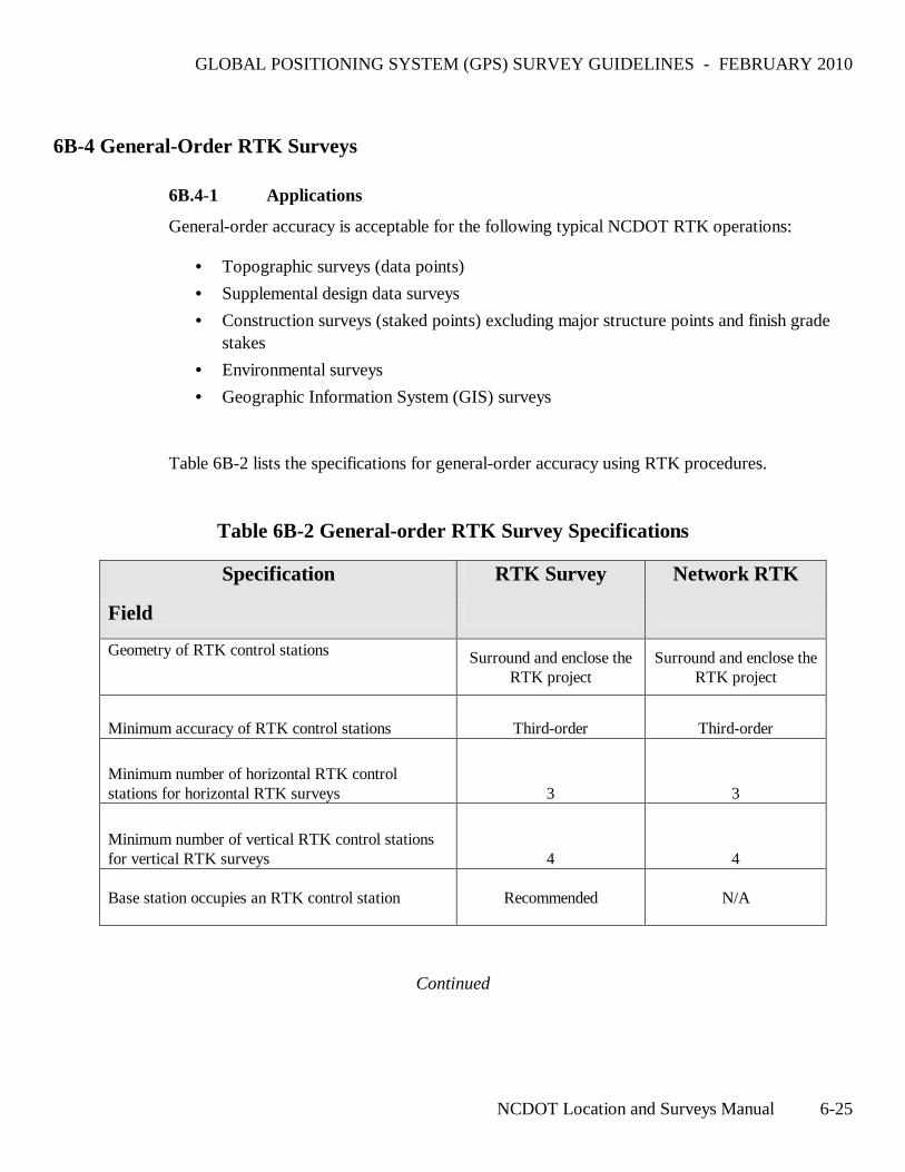
6B-4 General-Order RTK Surveys
6B.4-1 Applications
General-order accuracy is acceptable for the following typical NCDOT RTK operations:
• Topographic surveys (data points)
• Supplemental design data surveys
• Construction surveys (staked points) excluding major structure points and finish grade stakes
• Environmental surveys
• Geographic Information System (GIS) surveys
Table 6B-2 lists the specifications for general-order accuracy using RTK procedures.
Table 6B-2 General-order RTK Survey Specifications
Specification RTK Survey Network RTK
Field
Geometry of RTK control stations Surround and enclose the RTK project
Surround and enclose the RTK project
Minimum accuracy of RTK control stations Third-order Third-order
Minimum number of horizontal RTK control stations for horizontal RTK surveys 3 3
Minimum number of vertical RTK control stations for vertical RTK surveys 4 4
Base station occupies an RTK control station Recommended N/A
Continued
GLOBAL POSITIONING SYSTEM (GPS) SURVEY GUIDELINES - FEBRUARY 2010
NCDOT Location and Surveys Manual 6-26
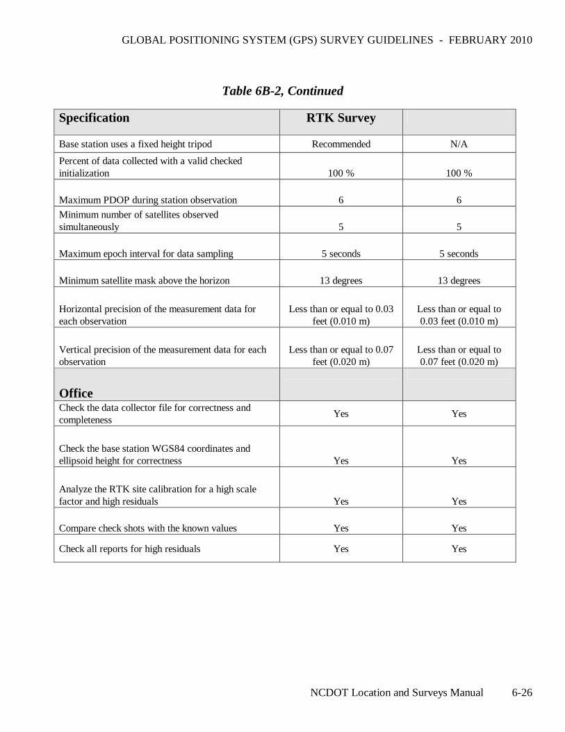
Table 6B-2, Continued
Specification RTK Survey
Base station uses a fixed height tripod Recommended N/A
Percent of data collected with a valid checked initialization 100 % 100 %
Maximum PDOP during station observation 6 6
Minimum number of satellites observed simultaneously 5 5
Maximum epoch interval for data sampling 5 seconds 5 seconds
Minimum satellite mask above the horizon 13 degrees 13 degrees
Horizontal precision of the measurement data for each observation
Less than or equal to 0.03 feet (0.010 m)
Less than or equal to 0.03 feet (0.010 m)
Vertical precision of the measurement data for each observation
Less than or equal to 0.07 feet (0.020 m)
Less than or equal to 0.07 feet (0.020 m)
Office
Check the data collector file for correctness and completeness
Yes Yes
Check the base station WGS84 coordinates and ellipsoid height for correctness Yes Yes
Analyze the RTK site calibration for a high scale factor and high residuals Yes Yes
Compare check shots with the known values Yes Yes
Check all reports for high residuals Yes Yes