61181 crane hose reprint 2006 new cover brown interior …€¦ · resistoflex specializes in...
TRANSCRIPT

www.PTFE-hose.comwww.PTFE-hose.com
HDM-2006

Resistoflex specializes in solving tough fluid handling problems.
Our customers make chemicals, paper, steel, and medicine. They process food, water, & minerals, convert energy, and build cars, ships and aircraft.
Our products combine the best materials with innovative manufacturing technology, to help customers operate more reliably, safely, and cost effectively.

About Resistoflex ..................................................................... 4Resistoflex Product Families .................................................... 5Choosing the Right Hose ......................................................... 6TR - Truck Rail Hose ................................................................ 7SuperFlexTM SFT-Si Hose ......................................................... 8TRC - FEP Rubber Covered Hose ........................................... 9TRC Rubber Covered Hose ................................................... 10 TRC Flared-Through Hose ......................................................11 SBT Braided Hose .................................................................. 12SBTF Braided Hose ............................................................... 13TMH Dual Containment System ............................................. 14 TMH Monel® Dual Containment System ................................. 15 SVT Seamless Vent Tubing Assembly ................................... 16 Twister TM CRC Hose ............................................................ 17 CB Convoluted Stainless Braided Hose ................................. 18 CBF Convoluted Stainless Braided Flared Through Hose ..... 19 CHB Convoluted Hastelloy® Braided Hose ............................. 20CKB Convoluted Kynar® Braided Hose .................................. 21 CPB Convoluted Polypropylene (PP) Braided Hose .............. 22 CPBF Convoluted PP Braided Flared Through Hose ............. 23 SHBT Smoothbore Chlorine/Bromine Transfer Hose ............. 24 CTH Convoluted Bore Chlorine/Bromine Transfer Hose ........ 25 Sanitary Tri-Clamp® and Mini-Sanitary Fittings ....................... 26 Sanitary I-Line and Bevel Seat Fittings .................................. 27 Cam and Groove Fittings ....................................................... 28Flanged (Rotating) Fittings ..................................................... 29Female JIC Fittings ................................................................ 30Pipe Thread Fittings ............................................................... 31Compression Tube Fittings ..................................................... 32Butt Weld Fittings ................................................................... 33Adapters and Accessories ............................................... 34 - 35Resistoflex Hose Qualification and Proof Testing ................... 36Permeation Considerations .................................................... 37Liner Conductivity ................................................................... 37Teflon® PTFE T-62 Properties Comparison ............................ 38Recommended Bolt Torque and Installation Instructions ....... 38Definitions and Hose Motion Guidelines ................................ 39Fraction-Decimal and Unit Conversions ................................. 40Temperature Conversion Chart .............................................. 41Resistoflex Hose Part Numbering System ...................... 42 - 43
Table of Contents
Smooth Bore Hoses
Convoluted Bore Hoses
Specialty Hoses
Fittings &
Accessories
Technical &
Sales Data
Introduction

4
About Resistofl exAbout Resistoflex…
280,000 sq. ft. Headquartersand Plant in Marion, NC
Resistoflex PLPP Shanghai, China
Resistoflex AsiaHeadquarters in
Singapore
Resistoflex B.V. inThe Netherlands
Resistoflex GmbHHeadquarters in Germany
Resistoflex started manufacturing polyvinyl alcohol (PVA) lined braided hose in New Jersey in 1936. The PVA lined hoses were superior to rubber hose for all types of marine, automotive, and aviation applications both commercial and military. At the end of WWII, the jet engine put new demands on existing hose materials in terms of corrosion resistance and higher temperature handling capabilities. It was at that time that Resistoflex began working with a new material called Teflon® PTFE, and eventually developed and patented a process to extrude PTFE tubing. Resistoflex invented PTFE lined hose in 1953 for the aerospace and chemical industries, and in 1956 introduced the world’s first pipe and fittings lined with Teflon® PTFE.
Today, Resistoflex manufactures corrosion-resistant plastic lined pipe, fittings, and Teflon® chemical hoses in our 280,000 sq. ft. plant in Marion, NC. In addition to our domestic capacity, Resistoflex has announced the acquisition of two European facilities, Resistoflex GmbH in Germany, and Resistoflex B.V. in The Nether-lands.
In 1995, Resistoflex Industrial added lined pipe and fittings manufacturing capacity in Singapore and estab-lished a joint venture in Thailand, making Resistoflex a truly global supplier of plastic lined piping products. To further strengthen the Resistoflex commitment to Asia, we opened a sales and fabrication center in China in 1997.
In 1998, Crane Resistoflex acquired the Plastic Line Piping Products division of The Dow Chemical Company (who invented Saran® lined pipe in 1943), making Resistoflex the largest and most technologically advanced lined piping manufacturer in the world. Resistoflex brings this vast array of experience and know-how to bear in the design, engineering, and manufacturing of corrosion-resistant plastic-lined pipe, fittings, and hoses.
Resistoflex flexible products are provided to the market through a network of knowledgeable and technically proficient manufacturer’s representatives and over 300 distributor locations. Please call the factory for your nearest representative or distributor.
Teflon® and Tefzel® are trademarks of DuPontSaran® is a trademark of The Dow Chemical Company

5
Resistofl ex Product Families
SPECIAL SHAPES►Custom fi ttings, manifolds, and small vessels►Lined with TEFZEL® ETFE►Available through 24” diameter
Thermalok Pipe►Stress relieved liner►Unlimited housing material options►Sizes ranging from 1” - 24” diameter
Swaged Pipe►Used exclusively for CONQUEST® and
MULTI-AXIS®
►Sizes ranging from 1” - 8”►Threaded fl anges and threaded
rotatable fl ange assemblies only
CONQUEST® CONNECTIONS►Patented fl angeless joint design►Performance of a welded system►Available in 1” - 4” for all liner types►Virtually zero maintenance
PLASTIC-LINED FITTINGSPP, Kynar® PVDF, and Tefl on® PFA fi ttings are all injection or transfer molded. TEFZEL® lined fi ttings and special shapes are roto-lined in custom housings. Tefl on® PTFE liners are made by isostatic molding.
FLANGED PLASTIC-LINED PIPEResistofl ex plastic lined pipe is made with
a locked-in liner to minimize the adverse affects of differential thermal expansion
between the liner and the steel. Available liners are: PP, Kynar® PVDF,
and Tefl on® PTFE or PFA.
► 2, 3, or 5 Convolute Construction► Bolt or Cable Limited► Tefl on® T-62 for Maximum Flex Life ► 1” - 24” Size Range► DI or SS Flanges Available
Expansion Joints of TEFLON®
6
Choosing the Right Hose
Liner StyleThere are two basic hose styles to be considered.1. Smoothbore: Hose liner has a smooth (TRUE ID) interior for
applications that require no bacteria entrapment.2. Convoluted: Hose liner is vacuum formed from a smooth liner for
flexibility, increased vacuum capabilities, and kink resistance. Since the convolutions are open pitched and helical, the media is not as likely to be trapped as with wrapped convoluted hose. They are usually used in applications requiring tight bends and frequent flexing.
TemperaturePlastics have a tendency to lose strength as the working temperature increases. Resistoflex offers a pressure/vacuum chart for each hose and fitting style based on minimum and maximum working temperature.
ApplicationCareful consideration must be taken on the working conditions of the hose. If the assembly is constantly flexing, surging, or in a bent application, it could change the capabilities of the assembly. Kink guards, vacuum spring wires and armor guard protectors can be installed in some applications that will prolong the life of the hose assembly.
MediaCertainly media is a big factor in which product should be used. One factor to consider is permeation. Some media can diffuse through the liner wall and attack the exterior of the hose. Examples are chlorine, bromine, and hydrogen fluoride, among others. (see the permeation discussion on page 37 for more information). Resistoflex offers various hose systems to combat permeation such as TMH, TMH-Monel® dual containment systems, and exotic braided products with corrosion-resistant braid materials such as Hastelloy®, 316SS, and polypropylene. Custom braid materials such as Kynar® PVDF can also be provided in special applications.
Pressure/VacuumThe pressure/vacuum rating coupled with temperature and application usually determines which hose product can be used.
End FittingsHose fittings come in multiple styles and sizes, and each are rated differently. A hose assembly’s actual operating pressure is usually limited by the fittings. Fitting material selection is another factor affecting corrosion resistance, purity conditions, and longevity of the assembly. In some cases, gaskets or clamping devices used will ultimately determine the final working pressure capabilities.
Testing/QualifyingResistoflex has a more vigorous quality assurance program than any other hose manufacturer. Resistoflex tests 100% of our hose assemblies both hydrostatically and pneumatically with nitrogen. This assures the end users of good fitting retention and a hose free of defects. See page 36 for testing and qualifying information.
Not All Teflon® is the Same
A frequent point of confusion and misapplication for users specifying hoses is the technical distinction among the various resin options available for high purity, chemical resistant hose liners. Adding to the confusion is the fact that various resins are marketed under the brand name Teflon®, including Teflon® PTFE (polytetrafluoroethylene) and Teflon® FEP (fluorinated ethylene propylene copolymer). Teflon® PTFE and Teflon® FEP are not equivalent in every hose application.
Teflon® PTFE T-62 has flex life up to 60 times greater than Teflon® FEP. In the case of a convoluted hose, pressurization imposes a flex load on the liner as the internal pressure attempts to straighten out the convolutions. Our experience has shown that premature failure may occur when FEP convoluted hoses are used in these applications due to its lower flex life.
Resistoflex does offer a rubber covered smooth bore Teflon® FEP lined hose. This hose is suitable in many applications and provides excellent chemical and abrasion resistance properties. Teflon® FEP is suitable in this hose construction because the EPDM materials limit the maximum use temperature. Further, the stiffness of the EPDM and its integrated wire reinforcement limits the radius to which the hose is flexed, thus reducing the potential for possible failure due to overbending.
When specifying hoses for use in harsh or high purity applications, it is important to verify which resin is being supplied. Be sure that you’re getting a resin suitable for your application. Not all fluoropolymer resins are created equal. Specifying hoses lined with Teflon® does not ensure that Teflon® PTFE will be supplied.

7S M O O T H B O R E
NOTE: Hose assembly pressure ratings may be limited by the fi ttings.
TR HOSE PRESSURE RATINGSM
AXI
MU
M V
AC
UU
M (ll H
g)
TR HOSE VACUUM RATINGS
OPERATING TEMPERATURE (F)
MA
XIM
UM
WO
RK
ING
PR
ESSU
RE
- PSI
G
OPERATING TEMPERATURE (F)
TR – Truck-Rail Hose
Inner core: Smooth Tefl on® PTFEReinforcement: Neoprene rubber
ConstructionExtra-thick, natural or conductive smooth bore Tefl on® PTFE liner locked internally inside (exclusive Resistofl ex Thermalok™ system) multiple plies of fabric-supported Neoprene rubber carcass.
Benefi ts • Hose design ensures integrity in frequent
handling/physical abuse applications • “One Piece” carcass resists fi tting
detachment better than crimped-on fi ttings
• Withstands excessive forces on the end fi ttings; will not separate but literally pull the hose in half where most crimped fi ttings separate
• Flanged assemblies are “Flared Through”, providing no exposed metal to the media
ApplicationsFor applications which must require a smooth inner bore for improved fl ow and is easily cleaned in place. TR assemblies are designed to withstand the everyday abuse and handling for loading/unloading trucks, rail cars, barges and process vessels.
FittingsAuxiliary fl anges can be added for fl ared end protection and easy replacement when ends are damaged, thus eliminating the need to replace the complete assembly.
External Protective Accessories
Contact factory for details.
Flared
Nominal Size Hose ID Hose OD Bend Radius Max. Working Pressure at 70oF (21oC)
Burst Pressure at 70oF (21oC) Natural
Part NumberInch DN Inch MM Inch MM Inch MM PSIG BAR PSIG BAR
1 25 0.875 22.2 1.625 41.3 18 457.2 150 10.3 600 41.4 See pages 46-47
1-1/2 40 1.375 34.9 2.188 55.6 18 457.2 150 10.3 600 41.4 See pages 46-47
2 50 1.875 47.6 2.813 71.5 24 609.6 150 10.3 600 41.4 See pages 46-47
3 80 2.813 71.5 3.813 96.9 30 762.0 150 10.3 600 41.4 See pages 46-47
4 100 3.813 96.9 4.938 125.4 36 914.4 150 10.3 600 41.4 See pages 46-47
Note: Vacuum ratings are based on testing done on straight assemblies. Bent assemblies may have reduced vacuum resistance.

8
SuperFlex SFT-Si Hose
Inner core: Smooth Tefl on® PTFEReinforcement: Fiberglass braid, 300-series stainless steel braid, and a silicone cover.
ConstructionNatural or conductive smooth bore Tefl on® PTFE liner. Liner is covered with a fi berglass braid externally bonded to the liner in a patented process. This is followed by a stainless steel braid and silicone cover.
Benefi ts • Ultra Flexible • True I.D. Sizes • Very high pressure capability • No Entrapment Issues • Wide Variety of Fittings Available • Validation Almost a Non-Issue • Vacuum-Rated
Approvals • FDA (reference 21 CFR 177.1550) • USDA (21 CFR 177.1550) • 3A (Sanitary Standards)
Fittings
Fitting Materials Carbon Steel 316 S.S. Solid Tefl on® Tefl on® Encapsulated Solid Kynar® Solid Polypropylene Monel® Hastelloy®
External Protective
Accessories See Page 35.
Nominal SizeHoseI.D.
HoseO.D.
Min.Bend
Radius
Max. Working Pressure
at 70oF (21oC)Burst Pressure at
70oF (21oC) NaturalLiner PartNumber
ConductiveLiner PartNumber
Inch DN Inch MM Inch MM Inch MM PSIG BAR PSIG BAR
1/4” 8 0.250 6.3 0.445 11.3 2.00 50.8 3,200 220.8 14,000 966 04-SFT-W 04-SFT-B
3/8” 10 0.375 9.5 0.710 18 2.50 63.5 2,500 172.5 10,000 690 06-SFT-W 06-SFT-B
1/2” 15 0.500 12.7 0.890 22.6 3.00 76.2 1,800 124.2 7,200 496.8 08-SFT-W 08-SFT-B
3/4” 20 0.750 19 1.120 28.4 5.00 127 1,000 69 6,000 414 12-SFT-W 12-SFT-B
NOTE: For assemblies, pressure ratings of fi ttings may be less than for the hose.
Fiberglass Braid Externally Bonded to the Tefl on® Tube in a Patented Process Silicone Cover
Stainless SteelReinforcing BraidTefl on® PTFE Liner
OPERATING TEMPERATURE (F)
MA
XIM
UM
WO
RK
ING
PR
ESSU
RE
- PSI
G
1/4” - 3/4”
350 400 450
MA
XIM
UM
VA
CU
UM
(ll Hg)
OPERATING TEMPERATURE (F)
SUPERFLEX HOSE PRESSURE RATINGS
SUPERFLEX HOSE VACUUM RATINGS
S M O O T H B O R E
Note: Vacuum ratings are based on testing done on straight assemblies. Bent assemblies may have reduced vacuum resistance.
Threaded Flanged Cam & Groove
Sanitary
(Patent Pending)
(consult factory for availability)
9
Nominal SizeHoseI.D.
HoseO.D.
Min.Bend
Radius
Max. Working Pressure
at 70oF (21oC)Burst Pressure at
70oF (21oC) NaturalLiner PartNumber
ConductiveLiner PartNumber
Inch DN Inch MM Inch MM Inch MM PSIG BAR PSIG BAR
1/4” 8 0.250 6.3 0.445 11.3 2.00 50.8 3,200 220.8 14,000 966 04-SFT-W 04-SFT-B
3/8” 10 0.375 9.5 0.710 18 2.50 63.5 2,500 172.5 10,000 690 06-SFT-W 06-SFT-B
1/2” 15 0.500 12.7 0.890 22.6 3.00 76.2 1,800 124.2 7,200 496.8 08-SFT-W 08-SFT-B
3/4” 20 0.750 19 1.120 28.4 5.00 127 1,000 69 6,000 414 12-SFT-W 12-SFT-B
TRC-FEP Rubber Covered Hose
S M O O T H B O R E
Nominal Size Hose ID Hose OD Bend Radius Max. Working Pressure at 70oF (21oC)
Burst Pressure at 70oF (21oC) Natural
Part NumberINCH DN INCH MM INCH MM INCH MM PSIG BAR PSIG BAR
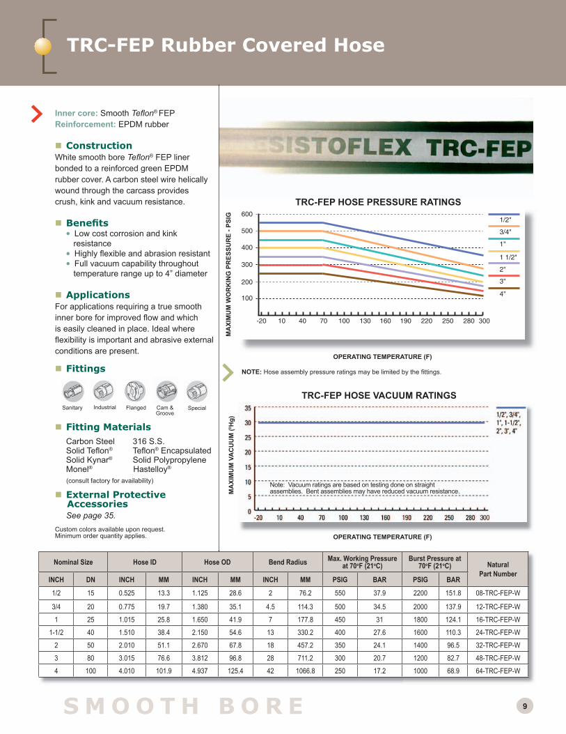
1/2 15 0.525 13.3 1.125 28.6 2 76.2 550 37.9 2200 151.8 08-TRC-FEP-W
3/4 20 0.775 19.7 1.380 35.1 4.5 114.3 500 34.5 2000 137.9 12-TRC-FEP-W
1 25 1.015 25.8 1.650 41.9 7 177.8 450 31 1800 124.1 16-TRC-FEP-W
1-1/2 40 1.510 38.4 2.150 54.6 13 330.2 400 27.6 1600 110.3 24-TRC-FEP-W
2 50 2.010 51.1 2.670 67.8 18 457.2 350 24.1 1400 96.5 32-TRC-FEP-W
3 80 3.015 76.6 3.812 96.8 28 711.2 300 20.7 1200 82.7 48-TRC-FEP-W
4 100 4.010 101.9 4.937 125.4 42 1066.8 250 17.2 1000 68.9 64-TRC-FEP-W
Inner core: Smooth Tefl on® FEPReinforcement: EPDM rubber
ConstructionWhite smooth bore Tefl on® FEP liner bonded to a reinforced green EPDM rubber cover. A carbon steel wire helically wound through the carcass provides crush, kink and vacuum resistance.
Benefi ts • Low cost corrosion and kink
resistance • Highly fl exible and abrasion resistant • Full vacuum capability throughout
temperature range up to 4” diameter
ApplicationsFor applications requiring a true smooth inner bore for improved fl ow and which is easily cleaned in place. Ideal where fl exibility is important and abrasive external conditions are present.
Fittings
Fitting Materials Carbon Steel 316 S.S. Solid Tefl on® Tefl on® Encapsulated Solid Kynar® Solid Polypropylene Monel® Hastelloy®
External Protective
Accessories See page 35. Custom colors available upon request. Minimum order quantity applies.
NOTE: Hose assembly pressure ratings may be limited by the fi ttings.
TRC-FEP HOSE PRESSURE RATINGS
MA
XIM
UM
VA
CU
UM
(ll Hg)
TRC-FEP HOSE VACUUM RATINGS
OPERATING TEMPERATURE (F)
MA
XIM
UM
WO
RK
ING
PR
ESSU
RE
- PSI
G
OPERATING TEMPERATURE (F)
Note: Vacuum ratings are based on testing done on straight assemblies. Bent assemblies may have reduced vacuum resistance.
Flanged Cam & Groove
Sanitary SpecialIndustrial
(consult factory for availability)

10 S M O O T H B O R E
NOTE: Hose assembly pressure ratings may be limited by the fi ttings.
TRC HOSE PRESSURE RATINGS
MA
XIM
UM
VA
CU
UM
(ll Hg)
TRC HOSE VACUUM RATINGS
OPERATING TEMPERATURE (F)
MA
XIM
UM
WO
RK
ING
PR
ESSU
RE
- PSI
G
OPERATING TEMPERATURE (F)
TRC Rubber Covered Hose
Inner core: Smooth Tefl on® PTFEReinforcement: EPDM rubber
ConstructionExtra-thick, natural or conductive smooth bore Tefl on® PTFE liner bonded to a reinforced blue or light gray/white EPDM rubber cover. A carbon steel wire helically wound through the carcass provides crush, kink and vacuum resistance.
Benefi ts • Extra-thick Tefl on® PTFE smooth liner
provides better permeation resistance (see permeation discussion on page 37) than thinner FEP lined hoses.
• EPDM cover provides great fl exibility • PTFE inner core provides better fl ex
life than FEP lined hoses (see pages 6 and 38)
ApplicationsDesigned for applications requiring a true smooth inner bore for improved fl ow and is easily cleaned in place. Ideal where abrasive external conditions, fl exing or permeation situations are present. Fittings
Fitting Materials Carbon Steel 316 S.S. Solid Tefl on® Tefl on® Encapsulated Solid Kynar® Solid Polypropylene Monel® Hastelloy®
External Protective
Accessories See Page 35.
Custom colors available upon request. Minimum order quantity applies.Custom colors available upon request. Minimum order quantity applies.Nominal Size Hose ID Hose OD Bend Radius Max. Working
Pressure at 70oF (21oC)
Burst Pressure at 70oF (21oC)
NaturalPart Number(Blue Cover)
ConductivePart Number(Blue Cover)
NaturalPart Number(Light Gray
Cover)
ConductivePart Number(Light Gray
Cover)INCH DN INCH MM INCH MM INCH MM PSIG BAR PSIG BAR
1/2 15 0.525 13.3 1.125 28.6 2 76.2 550 37.9 2200 151.8 08-TRC-W 08-TRC-B 08-WTRC-W 08-WTRC-B
3/4 20 0.775 19.7 1.380 35.1 4.5 114.3 500 34.5 2000 137.9 12-TRC-W 12-TRC-B 12-WTRC-W 12-WTRC-B
1 25 1.015 25.8 1.650 41.9 7 177.8 450 31 1800 124.1 16-TRC-W 16-TRC-B 16-WTRC-W 16-WTRC-B
1-1/2 40 1.510 38.4 2.150 54.6 13 330.2 400 27.6 1600 110.3 24-TRC-W 24-TRC-B 24-WTRC-W 24-WTRC-B
2 50 2.010 51.1 2.670 67.8 18 457.2 350 24.1 1400 96.5 32-TRC-W 32-TRC-B 32-WTRC-W 32-WTRC-B
Note: Vacuum ratings are based on testing done on straight assemblies. Bent assemblies may have reduced vacuum resistance.
OPERATING TEMPERATURE (F)
Flanged Cam & Groove
Sanitary SpecialIndustrial
(conductive liner shown)
(consult factory for availability)

11
TRC Flared-Through Hose
S M O O T H B O R E
TRC FLARE-THROUGH HOSE PRESSURE RATINGS
MA
XIM
UM
WO
RK
ING
PR
ESSU
RE
- PSI
G
OPERATING TEMPERATURE (F)
Size Hose I.D. Hose O.D. Min Bend Radius
Max. Working Pressure at 70oF (21oC)
Burst Pressure at 70oF (21oC) Natural Liner
Part NumberConductive Liner
Part NumberInch DN Inch MM Inch MM Inch MM PSIG BAR PSIG BAR1/2 15 0.500 12.7 1.02 25.9 2.5 63.5 500 34.5 2000 137.8 08-TRCF-W 08-TRCF-8
3/4 20 0.750 19.05 1.30 33 3 76.2 500 34.5 2000 137.8 12-TRCF-W 12-TRCF-8
1 25 1.000 25 1.56 39.6 4 101.6 400 27.6 1600 110.3 16-TRCF-W 16-TRCF-8
1-1/2 40 1.500 38.1 2.05 52 12 304.8 350 24.1 1400 96.5 24-TRCF-W 24-TRCF-8
2 50 2.000 51 2.56 65 12 304.8 300 20.7 1200 82.8 32-TRCF-W 32-TRCF-8
NOTE: For assemblies, pressure ratings of fi ttings may be less than for the hose.
Inner core: Smooth Tefl on® PTFEReinforcement: EPDM rubber
ConstructionExtra-thick, natural or conductive smooth bore Tefl on® PTFE liner bonded to a reinforced blue or light gray/white EPDM rubber cover. A carbon steel wire helically wound through the carcass provides crush, kink and vacuum resistance. Liner is fl ared out over the face of the fi tting.
Benefi ts • Patented Flare-Through Design • Patented ThermalokTM Process
Results in Interference Fit Liner • No Entrapment Issues • True Sanitary I.D. Dimensions • Wide Variety of Fittings Available • Full Vacuum-Rated
Fittings
Fitting Materials Carbon Steel 316 S.S. Solid Tefl on® Tefl on® Encapsulated Solid Kynar® Solid Polypropylene Monel® Hastelloy®
External Protective
Accessories See Page 35. Custom colors available upon request. Minimum order quantity applies.
Consult factory for vacuum ratings of 1 1/2” - 2” sizes
MA
XIM
UM
VA
CU
UM
(ll Hg)
TRC FLARE-THROUGH HOSE VACUUM RATINGS
OPERATING TEMPERATURE (F)
Note: Vacuum ratings are based on testing done on straight assemblies. Bent assemblies may have reduced vacuum resistance.
(consult factory for availability)
FlaredFlange
Flared Cam & Groove
FlaredSanitary

12
For 1/4"-3/8" high temperature pressure ratings, consult factory
1/4"
3/8"
3/4" - 1 1/2"
1/2"
S M O O T H B O R E
SBT Braided Hose
Inner core: Smooth Tefl on® PTFEReinforcement: 300-series stainless steel braid
ConstructionExtra-thick, natural or conductive smooth bore Tefl on® PTFE liner braided with 300-series stainless steel heavy gauge wire (1” and 1-1/2” are double-braided for extra kink resistance).
Benefi ts • Provides higher working temperatures
and full vacuum capabilities • Heavy gauge stainless steel braid
is corrosion resistant against most chemicals
• Flanged assemblies can be “Flared Through” providing no bacteria traps
• Available in long lengths • “True ID”, for superior fl ow characteristics
and easy dimensional matchup
ApplicationsDesigned for applications requiring a true smooth inner bore for improved fl ow and which is easily cleaned in place. Excellent in static applications where handling, fl exing or abuse is minimal.
Fittings
Fitting Materials Carbon Steel 316 S.S. Solid Tefl on® Tefl on® Encapsulated Solid Kynar® Solid Polypropylene Monel® Hastelloy®
External Protective
Accessories See Page 35. Custom colors available upon request. Minimum order quantity applies.Extruded silicone protection sleeve offered with designation SBT-Si
NOTE: Hose assembly pressure ratings may be limited by the fi ttings.
SBT HOSE PRESSURE RATINGSM
AXI
MU
M V
AC
UU
M (ll H
g)
SBT HOSE VACUUM RATINGS
OPERATING TEMPERATURE (F)
MA
XIM
UM
WO
RK
ING
PR
ESSU
RE
- PSI
G
OPERATING TEMPERATURE (F)
Threaded Flanged Cam & Groove
Sanitary
Nominal Size Hose ID Hose OD Bend Radius Max. Working Pressure at 70oF (21oC)
Burst Pressure at 70oF (21oC) Natural
Part NumberConductive
Part NumberInch DN Inch MM Inch MM Inch MM PSIG BAR PSIG BAR1/4 8 0.250 6.3 .375 9.5 3 50.8 3000 207 12000 828 04-SBT-W 04-SBT-B
3/8 10 0.375 9.5 .515 13 5 127 2000 138 8000 552 06-SBT-W 06-SBT-B
1/2 15 0.500 12.7 0.633 16.1 6.5 165.1 1425 98.2 5700 393 08-SBT-W 08-SBT-B
3/4 20 0.750 19.1 0.875 22.2 8.2 208.3 1000 68.9 4000 275.8 12-SBT-W 12-SBT-B
1 25 1.000 25.4 1.190 30.2 12 304.8 1000 68.9 4000 275.8 16-SBT-W 16-SBT-B
1-1/2 40 1.500 38.1 1.762 44.8 14 355.6 1000 68.9 4000 275.8 24-SBT-W 24-SBT-B
Note: Vacuum ratings are based on testing done on straight assemblies. Bent assemblies may have reduced vacuum resistance.
(consult factory for availability)

13
For 1/4"-3/8" high temperature pressure ratings, consult factory
1/4"
3/8"
3/4" - 1 1/2"
1/2"
SBTF Braided Hose
Inner core: Smooth Tefl on® PTFEReinforcement: 300-series stainless steel braid
ConstructionExtra-thick, natural or conductive smooth bore Tefl on® PTFE liner braided with 300-series stainless steel heavy gauge wire (1” and 1-1/2” are double-braided for extra kink resistance).
Benefi ts • “Flared Through” system allows Tefl on®
PTFE protection of all wetted surfaces • Provides higher working temperatures
and full vacuum capabilities • Heavy gauge stainless steel braid
is corrosion resistant against most chemicals
• Available in long lengths • “True ID”, for superior fl ow characteristics
and easy dimensional matchup
ApplicationsDesigned for applications requiring a true smooth inner bore for improved fl ow and which is easily cleaned in place. Excellent in static applications where handling, fl exing or abuse is minimal.
Fittings
Fitting Materials Carbon Steel 316 S.S. Solid Tefl on® Tefl on® Encapsulated Solid Kynar® Solid Polypropylene Monel® Hastelloy®
External Protective
Accessories See Page 35. Custom colors available upon request. Minimum order quantity applies.Extruded silicone protection sleeve offered with designation SBT-Si
(consult factory for availability)
S M O O T H B O R E
Nominal Size Hose ID Hose OD Bend Radius Max. Working Pressure at 70oF (21oC)
Burst Pressure at 70oF (21oC) Natural
Part NumberConductive
Part NumberInch DN Inch MM Inch MM Inch MM PSIG BAR PSIG BAR1/2 15 0.540 13.7 .760 19.3 8.2 208.3 275 18.9 1100 75.8 08-SBT-W 08-SBT-B
3/4 20 0.750 19.1 .875 22.2 8.2 208.3 275 18.9 1100 75.8 12-SBT-W 12-SBT-B
1 25 1.000 25.4 1.190 30.2 12 304.8 275 18.9 1100 75.8 16-SBT-W 16-SBT-B
1-1/2 40 1.500 38.1 1.762 44.8 14 355.6 275 18.9 1100 75.8 24-SBT-W 24-SBT-B
FlaredFlange
Flared Cam & Groove
FlaredSanitary
1/2"-1 1/2"
SBTF HOSE PRESSURE RATINGS
MA
XIM
UM
WO
RK
ING
PR
ESSU
RE
- PSI
G
OPERATING TEMPERATURE (F)
MA
XIM
UM
VA
CU
UM
(ll Hg)
SBT HOSE VACUUM RATINGS
OPERATING TEMPERATURE (F)
Note: Vacuum ratings are based on testing done on straight assemblies. Bent assemblies may have reduced vacuum resistance.

14 S M O O T H B O R ES M O O T H B O R E
TMH Dual Containment System
Primary Containment (inner core): Smooth Tefl on® PTFE
Secondary containment: 316 stainless steel, convoluted metal hose
Reinforcement: 316 stainless steel braid
ConstructionExtra-thick natural or conductive smooth bore Tefl on® PTFE liner locked inside (exclusive Thermalok™ system) a 316 stainless steel carcass with welded fl ange retainers and over braided with 316 stainless steel. The liner is “Flared Through” the stub ends providing no exposed metal fi ttings to the media.
Benefi ts• Dual Containment - welded 316 SS carcass acts
as a barrier between the inner liner of Tefl on® and the atmosphere
• Reduced risk of the catastrophic failure and environmental releases
• Vent acts as a warning system, allowing the hose to be removed prior to failure
• A coupling can be installed over the vent hole to contain or recycle permeants.
ApplicationsFor severe service applications where leak prevention is imperative.
Fittings
Auxiliary fl anges can be added for fl anged end protection and easy replacement when ends are damaged, thus eliminating the need to replace the complete assembly
Optional Vent Systems• Vent hole
• Vent coupling 1/8" female pipe • Hastelloy® leak detection system (factory)
External Protective AccessoriesContact factory for details.
NOTE: Hose assembly pressure ratings may be limited by the fi ttings.
TMH HOSE PRESSURE RATINGS
MA
XIM
UM
VA
CU
UM
(ll Hg)
TMH HOSE VACUUM RATINGS
OPERATING TEMPERATURE (F)
MA
XIM
UM
WO
RK
ING
PR
ESSU
RE
- PSI
G
OPERATING TEMPERATURE (F)
Nominal Size Hose ID Hose OD Bend Radius Max. Working Pressure at 70oF (21oC)
Burst Pressure at 70oF (21oC) Natural
Part NumberInch DN Inch MM Inch MM Inch MM PSIG BAR PSIG BAR
1 25 0.875 22.2 1.590 40.4 12 304.8 750 51.7 3000 206.8 See pages 46-47
1-1/2 40 1.375 34.9 2.270 57.7 15 381.0 565 39.0 2260 155.8 See pages 46-47
2 50 1.875 47.6 2.910 73.9 21 533.4 500 34.5 2000 137.9 See pages 46-47
3 80 2.797 71.0 3.690 93.7 28 711.2 288 19.9 1152 79.4 See pages 46-47
4 100 3.766 95.7 4.840 122.9 46 1168.4 250 17.2 1000 68.9 See pages 46-47
6 150 5.688 144.5 7.160 181.9 65 1651.0 175 12.1 700 48.3 See pages 46-47
8 200 7.718 196.0 9.310 236.5 89 2260.6 212 14.6 848 58.5 See pages 46-47
Note: Vacuum ratings are based on testing done on straight assemblies. Bent assemblies may have reduced vacuum resistance.
(shown with optional 1/8” vent port accessory)
FlaredFlange
Flared Cam & Groove
FlaredSanitary
TMH with Flared Sanitary Tri-Clamp

15S M O O T H B O R ES M O O T H B O R E
NOTE: Hose assembly pressure ratings may be limited by the fi ttings.
TMH-MONEL® PRESSURE RATINGS
MA
XIM
UM
VA
CU
UM
(ll Hg)
TMH-MONEL® HOSE VACUUM RATINGS
OPERATING TEMPERATURE (F)
MA
XIM
UM
WO
RK
ING
PR
ESSU
RE
- PSI
G
OPERATING TEMPERATURE (F)
TMH-Monel® Dual Containment System
Primary Containment (inner core): Smooth Tefl on®
PTFE Secondary containment: Monel® 400, convoluted
metal hose (Hastelloy available)
Reinforcement: Heavy gauge Monel® braid
ConstructionExtra-thick natural or conductive smooth bore Tefl on® PTFE liner locked inside (exclusive Thermalok™ system) a Monel® 400 carcass with welded Monel® fl ange retainers and over braided with heavy gauge Monel®. The liner is “Flared Through” the stub ends providing no exposed metal fi ttings to the media.
Benefi ts • Dual Containment - welded Monel® carcass acts as
a barrier between the inner liner of Tefl on® and the atmosphere (excellent chlorine transfer hose)
• Reduced risk of the catastrophic failure and environmental releases.
• Vent acts as a warning system, allowing the hose to be removed prior to failure.
• A coupling can be installed over the vent hole to contain or recycle permeants.
ApplicationsTMH-Monel® assemblies with Thermalok™ PTFE liner designed to withstand extreme corrosive applications such as chlorine, HCl, where leak prevention is imperative and chlorine can stress crack stainless steel.
FittingsAuxiliary fl anges can be added for fl ared end protection and easy replacement when ends are damaged, thus eliminating the need to replace the complete assembly.
Optional Vent Systems • Vent hole • Vent coupling 1/8" female pipe • Hastelloy® leak detection system (factory)
External Protective Accessories Contact factory for details.
FlaredFlange
Nominal Size Hose ID Hose OD Bend Radius Max. Working Pressure at 70oF (21oC)
Burst Pressure at 70oF (21oC) Natural
Part NumberInch DN Inch MM Inch MM Inch MM PSIG BAR PSIG BAR
1 25 0.875 22.2 1.590 40.4 12 304.8 692 47.7 2768 190.8 See pages 46-47
1-1/2 40 1.375 34.9 2.270 57.7 15 381.0 419 28.9 1676 115.5 See pages 46-47
2 50 1.875 47.6 2.910 73.9 21 533.4 313 21.6 1252 86.3 See pages 46-47
3 80 2.797 71.0 3.690 93.7 28 711.2 300 20.7 1200 82.7 See pages 46-47
4 100 3.766 95.7 4.840 122.9 46 1168.4 263 18.1 1052 72.5 See pages 46-47
Note: Vacuum ratings are based on testing done on straight assemblies. Bent assemblies may have reduced vacuum resistance.

16 C O N V O L U T E D
Nominal Size Hose ID Hose OD Bend Radius Max. Working Pressure at 70oF (21oC)
Burst Pressure at 70oF (21oC) Natural
Part NumberInch DN Inch MM Inch MM Inch MM PSIG BAR PSIG BAR1/2 15 0.500 12.7 0.700 17.8 2 50.8 25 1.7 100 6.9 See pages 46-47
3/4 20 0.760 19.3 0.990 25.1 2 50.8 25 1.7 100 6.9 See pages 46-47
1 25 1.025 26.0 1.280 32.5 3 76.2 25 1.7 100 6.9 See pages 46-47
1-1/2 40 1.525 38.7 1.960 49.8 4.5 114.3 20 1.4 80 5.5 See pages 46-47
2 50 2.025 51.4 2.390 60.7 8 203.2 20 1.4 80 5.5 See pages 46-47
3 80 2.913 74.0 3.622 92.0 14 355.6 20 1.4 80 5.5 See pages 46-47
4 100 3.937 100.0 4.921 125.0 20 508.0 15 1.0 60 4.1 See pages 46-47
Seamless Vent Tubing
ConstructionExtra-thick, natural or conductive “seamless” helical convoluted Tefl on® PTFE with “Flared Through” fl anges, pipe or tubing sized cuffs or crimped-on fi tting options.
Benefi tsSVT - “Seamless” Vent Tubing assemblies are vacuum formed in an open pitched, helical design for easy cleaning.
• “Flared Through” and cuffed end system allows Tefl on® PTFE protection of all wetted surfaces• Eliminates bacteria traps • Crush resistant and easy to fl ex• Fitting-to-hose crevices are eliminated,
increasing fl ow rates• Optional external vacuum wire provides
increased crush resistance and vacuum capability.
ApplicationsFor low pressure vent or vapor recovery systems, pharmaceutical, chemical, food and beverage, and other applications requiring an extremely fl exible, lightweight Tefl on® PTFE assembly.
Fittings
Fitting MaterialsCarbon Steel 316 S.S.
Solid Tefl on® Tefl on® Encapsulated Solid Kynar® Solid Polypropylene Monel® Hastelloy®
External Protective Accessories See Page 35.
SVT HOSE PRESSURE RATINGSM
AXI
MU
M V
AC
UU
M (ll H
g)
SVT HOSE VACUUM RATINGS
OPERATING TEMPERATURE (F)
MA
XIM
UM
WO
RK
ING
PR
ESSU
RE
- PSI
G
Degrees Fahrenheit (consult factory for use at elevated temperatures)
SVT–Seamless Vent Tubing Assembly
Cuff
SanitaryCam & Groove
FlangedThreaded
2” - 4” not recom-mended for vacuum service
Note: Vacuum ratings are based on testing done on straight assemblies. Bent assemblies may have reduced vacuum resistance.
(conductive liner shown)
Wire wrap available
FlaredFlange
Flared Cam & Groove
FlaredSanitary
(consult factory for availability)

17
CRC HOSE PRESSURE RATINGS
MA
XIM
UM
WO
RK
ING
PR
ESSU
RE
- PSI
G
OPERATING TEMPERATURE (F)
Size Hose I.D. Hose O.D. Min. Bend RadiusMax. Working
Pressure at 70oF (21oC)
Burst Pressure at 70oF (21oC) Natural Liner
Part NumberConductive Liner
Part NumberInch DN Inch MM Inch MM Inch MM PSIG BAR PSIG BAR1/2 15 0.471 12 0.970 24.6 0.500 12.7 785 54.1 3140 216.5 08-CRC-W 08-CRC-B
3/4 20 0.720 18.3 1.250 31.7 0.750 19 570 39.3 2280 157.2 12-CRC-W 08-CRC-B
1 25 0.970 24.6 1.560 39.6 1.000 25.4 350 24.1 1400 96.5 16-CRC-W 08-CRC-B
1-1/2 40 1.540 39 2.240 56.9 1.500 38.1 295 20.33 1180 81.4 24-CRC-W 08-CRC-B
2 50 1.970 50 2.670 67.8 2.000 50.8 275 19 1100 75.8 32-CRC-W 08-CRC-B
NOTE: For assemblies, pressure ratings of fi ttings may be less than for the hose.
Inner core: ConvolutedTefl on® PTFE
Reinforcement: SS reinforcing wire and EPDM cover
Convoluted Tefl on® PTFE Rubber-Covered Hose
Benefi ts • Ultra Flexible • Virtually Kink-Proof • Self-Draining Helical Convolutes • Wide Variety of Fittings Available • Tough Rubber Outer Cover • Vacuum-Rated • Patent Pending
Fittings
Fitting Materials Carbon Steel 316 S.S. Solid Tefl on® Tefl on® Encapsulated Solid Kynar® Solid Polypropylene Monel® Hastelloy®
External Protective
Accessories See Page 35.
MA
XIM
UM
VA
CU
UM
(ll Hg)
CRC HOSE VACUUM RATINGS
OPERATING TEMPERATURE (F)
TwisterTM CRC Hose
Note: Vacuum ratings are based on testing done on straight assemblies. Bent assemblies may have reduced vacuum resistance.
O.D. I.D.
Flanged Cam & Groove
Sanitary SpecialFlared(future)
Industrial
(Patent Pending)
C O N V O L U T E D
(consult factory for availability)

18 C O N V O L U T E D
CB–Convoluted Stainless Braided
Inner core: “Seamless” convoluted Tefl on® PTFEReinforcement: 316 stainless steel
braid (Hastelloy® and custom braids available)
ConstructionExtra-thick natural or conductive “seamless” helical convoluted Tefl on® PTFE liner braided with 316 stainless steel heavy gauge wire.
Benefi ts• Open-pitched, helical convolutions for
easy cleaning• Rated for both medium pressure and
full vacuum applications• Crush resistant and easy to fl ex
• Tighter bend radii than smooth bore • Optional external vacuum wire
provides increased crush resistance and vacuum capability.
ApplicationsFor pharmaceutical, chemical, food and beverage, and other applications requiring an extremely fl exible, lightweight Tefl on® PTFE hose assembly.
Fittings
See CBF, pg. 19, for “Flared Through” assemblies.
Fitting MaterialsCarbon Steel 316 S.S.
Solid Tefl on® Tefl on® Encapsulated Solid Kynar® Solid Polypropylene Monel® Hastelloy®
External Protective
Accessories See Page 35.
NOTE: Hose assembly pressure ratings may be limited by the fi ttings and options.
CB HOSE PRESSURE RATINGSM
AXI
MU
M V
AC
UU
M (ll H
g)
CB HOSE VACUUM RATINGS
OPERATING TEMPERATURE (F)
MA
XIM
UM
WO
RK
ING
PR
ESSU
RE
- PSI
G
OPERATING TEMPERATURE (F)
C O N V O L U T E D
Nominal Size Hose ID Hose OD Bend Radius Max. Working Pressure at 70oF (21oC)
Burst Pressure at 70oF (21oC) Natural
Part NumberConductive
Part NumberInch DN Inch MM Inch MM Inch MM PSIG BAR PSIG BAR
1/2 15 0.470 11.9 0.748 19 2 50.8 1425 98.2 5700 393.0 08-CB-W 08-CB-B
3/4 20 0.720 18.3 1.048 26.6 2.75 69.9 1300 89.6 5200 358.5 12-CB-W 12-CB-B
1 25 0.970 24.6 1.354 34.4 4 101.6 1100 75.8 4400 303.3 16-CB-W 16-CB-B
1-1/2 40 1.540 39.1 2.034 51.7 6 152.4 700 48.3 2800 193.0 24-CB-W 24-CB-B
2 50 1.970 50.0 2.464 62.6 7.5 190.5 525 36.2 2100 144.8 32-CB-W 32-CB-B
3 50 2.913 74.0 3.702 94.0 14 355.6 350 24.1 1400 96.6 48-CB-W 48-CB-B
4 50 3.937 100.0 5.000 127.0 16 406.4 275 19 1100 75.9 64-CB-W 64-CB-B
Note: Vacuum ratings are based on testing done on straight assemblies. Bent assemblies may have reduced vacuum resistance.
(conductive liner shown)
Threaded Flanged Cam & Groove
Sanitary Flared
Optional Wire Wrap(pressure ratings with wire wrap are shown on Pg. 19)
(consult factory for availability)

19C O N V O L U T E D
CBF– Convoluted Stainless Braided Flared-Through
Inner core: “Seamless” convoluted Tefl on® PTFEReinforcement: 316 stainless steel braid
(Hastelloy® and custom braids available)
ConstructionExtra-thick natural or conductive “seamless” helical convoluted Tefl on® PTFE liner braided with 316 stainless steel heavy gauge wire. The liner is passed through the inside of the fi tting and fl ared over the face, creating a self-gasketing sealing surface.
Benefi ts • Open-pitched, helical convolutions for easy
cleaning • “Flared Through” system allows Tefl on® PTFE
protection of all wetted surfaces • Eliminates bacteria traps • Fitting-to-hose crevices are also eliminated,
thereby increasing fl ow rates • Optional external vacuum wire provides
increased crush resistance and vacuum capability.
ApplicationsFor pharmaceutical, chemical, food and beverage, and other applications requiring an extremely fl exible, lightweight Tefl on® PTFE hose with no metal exposed to the media.
Fittings
Fitting Materials Carbon Steel 316 S.S. Solid Tefl on® Tefl on® Encapsulated Solid Kynar® Solid Polypropylene Monel® Hastelloy®
External Protective Accessories See Page 35.
* Use these pressure ratings for CB hose with optional wire wrapNOTE: Hose assembly pressure ratings may be limited by the fi ttings.
CBF HOSE PRESSURE RATINGS*
MA
XIM
UM
VA
CU
UM
(ll Hg)
CBF HOSE VACUUM RATINGS
MA
XIM
UM
WO
RK
ING
PR
ESSU
RE
- PSI
G
OPERATING TEMPERATURE (F)
Nominal Size Hose ID Hose OD Bend Radius Max. Working Pressure at 70oF (21oC)
Burst Pressure at 70oF (21oC) Natural
Part NumberConductive
Part NumberInch DN Inch MM Inch MM Inch MM PSIG BAR PSIG BAR
1/2 15 0.470 11.9 0.748 19 2 50.8 500 34.5 2000 137.9 08-CB-W 08-CB-B
3/4 20 0.720 18.3 1.048 26.6 2.75 69.9 500 34.5 2000 137.9 12-CB-W 12-CB-B1 25 0.970 24.6 1.354 34.4 4 101.6 500 34.5 2000 137.9 16-CB-W 16-CB-B
1-1/2 40 1.540 39.1 2.034 51.7 6 152.4 350 24.1 1400 96.5 24-CB-W 24-CB-B2 50 1.970 50.0 2.464 62.6 7.5 190.5 250 17.2 1000 68.9 32-CB-W 32-CB-B3 75 2.913 74.0 3.702 94.0 14 355.6 175 12.1 700 48.4 48-CB-W 48-CB-B4 100 3.937 100.0 5.000 127.0 16 406.4 150 10.3 600 41.2 64-CB-W 64-CB-B
OPERATING TEMPERATURE (F)
MA
XIM
UM
VA
CU
UM
(H
g)
Note: Vacuum ratings are based on testing done on straight assemblies. Bent assemblies may have reduced vacuum resistance.
OPERATING TEMPERATURE (F)
1/2"-1"
FlaredFlange
Flared Cam & Groove
FlaredSanitary
Optional Wire Wrap
(consult factory for availability)
Flared-Through Female Cam Flared-Through Sanitary Tri-Clamp

20 C O N V O L U T E D
CHB–Convoluted Hastelloy® Braided
Inner core: “Seamless” convoluted Tefl on® PTFEReinforcement: Hastelloy® C276 heavy
gauge wire braid
ConstructionExtra-thick conductive “seamless” helical convoluted Tefl on® PTFE liner braided with Hastelloy® C276 heavy gauge wire braid.
Benefi ts• Open-pitched, helical convolutions for easy
cleaning• Rated for both medium pressure and full vacuum
applications• Crush resistant and easy to fl ex• Tighter bend radii than smooth bore alternatives• Hastelloy® C276 braid is resistant to most
chemicals introduced to the external surface of the hose through permeation, spillage, or atmospheric conditions
• Optional external vacuum wire provides increased crush resistance and vacuum capability.
ApplicationsFor applications requiring an extremely fl exible, lightweight Tefl on® PTFE hose assembly conveying chemicals that permeate aggressively, or for harsh atmospheric conditions that require extreme corrosion resistance on the exterior of the assembly.
Fittings
Fitting MaterialsCarbon Steel 316 S.S.
Solid Tefl on® Tefl on® Encapsulated Solid Kynar® Solid Polypropylene Monel® Hastelloy®
External Protective Accessories See Page 35.
CHB HOSE VACUUM RATINGS
Threaded Flanged Cam & Groove
Sanitary
MA
XIM
UM
VA
CU
UM
(ll Hg)
OPERATING TEMPERATURE (F)
MA
XIM
UM
WO
RK
ING
PR
ESSU
RE
- PSI
G
OPERATING TEMPERATURE (F)
NOTE: Hose assembly pressure ratings may be limited by the fi ttings.
CHB HOSE PRESSURE RATINGS
Nominal Size Hose ID Hose OD Bend Radius Max. Working Pressure at 70oF (21oC)
Burst Pressure at 70oF (21oC) Natural
Part NumberConductive
Part NumberInch DN Inch MM Inch MM Inch MM PSIG BAR PSIG BAR
1/2 15 0.470 11.9 0.748 19.0 2 50.8 500 34.5 2500 172.4 08-CHB-W 08-CHB-B
3/4 20 0.720 18.3 1.048 26.6 2.75 63.5 500 34.5 2500 172.4 12-CHB-W 12-CHB-B
1 25 0.970 24.6 1.354 34.4 4 101.6 500 34.5 2500 172.4 16-CHB-W 16-CHB-B
1-1/2 40 1.540 39.1 2.034 51.7 6 152.4 375 25.9 1875 129.3 24-CHB-W 24-CHB-B
2 50 1.970 50.0 2.464 62.6 7.5 190.5 250 17.2 1250 86.2 32-CHB-W 32-CHB-B
Note: Vacuum ratings are based on testing done on straight assemblies. Bent assemblies may have reduced vacuum resistance.
(conductive liner shown)
(consult factory for availability)
Flared

21C O N V O L U T E D
MA
XIM
UM
VA
CU
UM
(ll Hg)
OPERATING TEMPERATURE (F)
MA
XIM
UM
WO
RK
ING
PR
ESSU
RE
- PSI
G
OPERATING TEMPERATURE (F)
Nominal Size Hose ID Hose OD Bend Radius Weightlbs./ft.
Max. Working Pressure at 70oF (21oC)
Burst Pressure at 70oF (21oC) Natural
Part NumberConductive
Part NumberInch DN Inch MM Inch MM Inch MM PSIG BAR PSIG BAR
1/2 15 0.500 12.7 0.960 24.9 2 50.8 0.17 500 34.5 2500 172.4 08-CKB-W 08-CKB-B
3/4 20 0.740 18.8 1.250 31.8 2.5 69.9 0.26 500 34.5 2500 172.4 12-CKB-W 12-CKB-B
1 25 1.005 25.5 1.560 39.6 6 101.6 0.42 500 34.5 2500 172.4 16-CKB-W 16-CKB-B
1-1/2 40 1.505 38.2 2.240 56.9 10 152.4 0.74 375 25.9 1875 129.3 24-CKB-W 24-CKB-B
2 50 2.005 50.9 2.670 67.8 12 190.5 0.82 375 17.2 1875 86.2 32-CKB-W 32-CKB-B
NOTE: Hose assembly pressure ratings may be limited by the fi ttings.
CKB–Convoluted Kynar® Braided
CKB HOSE PRESSURE RATINGS
CKB HOSE VACUUM RATINGS
Inner core: “Seamless” convoluted Tefl on® PTFEReinforcement: Kynar® PVDF heavy
double braid
ConstructionExtra-thick, natural or conductive “seamless” helical convoluted Tefl on® PTFE liner braided with Kynar® PVDF monofi lament heavy gauge wire braid.
Benefi ts • Open-pitched, helical convolutions for easy
cleaning • Rated for both medium pressure and full
vacuum applications • Crush resistant and easy to fl ex • Tighter bend radii than smooth bore
alternatives • Kynar® braid is resistant to most chemicals
introduced to the external surface of the hose through permeation, spillage, or atmospheric conditions.
• Optional external vacuum wire provides increased crush resistance and vacuum capability.
ApplicationsFor applications requiring an extremely fl exible, lightweight Tefl on® PTFE hose assembly conveying chemicals that permeate aggressively, or for harsh atmospheric conditions that require extreme corrosion resistance on the exterior of the assembly.
Fittings
Fitting Materials Carbon Steel 316 S.S. Solid Tefl on® Tefl on® Encapsulated Solid Kynar® Solid Polypropylene Monel® Hastelloy®
External Protective Accessories See Page 35.
Threaded Flanged Cam & Groove
Sanitary
Note: Vacuum ratings are based on testing done on straight assemblies. Bent assemblies may have reduced vacuum resistance.
(conductive liner shown)
(consult factory for availability)

22 C O N V O L U T E D
CPB–Convoluted Polypropylene Braided
Inner core: “Seamless” convoluted Tefl on® PTFEReinforcement: Blue polypropylene,
UV-stabilized braid
ConstructionExtra-thick natural or conductive “seamless” helical convoluted Tefl on® PTFE liner braided with thick, high density, polypropylene braid.
Benefi ts • Open-pitched, helical convolutions for easy
cleaning • Rated for both medium pressure and full
vacuum applications • Crush resistant and easy to fl ex • Tighter bend radii than smooth bore
alternatives • Abrasion resistant braid • Reduced risk of hand injury from metal braids • Optional external vacuum wire provides
increased crush resistance and vacuum capability.
ApplicationsFor pharmaceutical, chemical, food and beverage, and other applications requiring an extremely fl exible, lightweight Tefl on® PTFE hose assembly, with better abrasion resistance than metal braids.
Fittings
See CPBF (Page 23) for “Flared Through” assemblies.
Fitting Material Availability Carbon Steel 304/316 S.S. Solid Tefl on® Tefl on®Encapsulated Solid Kynar® Solid Polypropylene Monel® Hastelloy®
External Protective Accessories See page 39
NOTE: Hose assembly pressure ratings may be limited by the fi ttings.
CPB HOSE PRESSURE RATINGS
MA
XIM
UM
VA
CU
UM
(ll Hg)
CPB HOSE VACUUM RATINGS
OPERATING TEMPERATURE (F)
MA
XIM
UM
WO
RK
ING
PR
ESSU
RE
- PSI
G
OPERATING TEMPERATURE (F)
Threaded Flanged Cam & Groove
Sanitary
Nominal Size Hose ID Hose OD Bend Radius Max. Working Pressure at 70oF (21oC)
Burst Pressure at 70oF (21oC) Natural
Part NumberConductive
Part NumberInch DN Inch MM Inch MM Inch MM PSIG BAR PSIG BAR
1/2 15 0.470 11.9 0.855 21.7 2 50.8 475 32.7 1900 131 08-CPB-W 08-CPB-B
3/4 20 0.720 18.3 1.160 29.5 2.75 69.9 425 29.3 1700 117.2 12-CPB-W 12-CPB-B
1 25 0.970 24.6 1.440 36.6 4 101.6 375 25.8 1500 103.4 16-CPB-W 16-CPB-B
1-1/2 40 1.540 39.1 2.155 54.7 6 152.4 325 22.4 1300 89.6 24-CPB-W 24-CPB-B
2 50 1.970 50.0 2.560 65.0 7.5 190.5 275 19 1100 75.8 32-CPB-W 32-CPB-B
3 75 2.913 74.0 3.922 99.6 14 355.6 225 15.5 900 62 48-CPB-W 48-CPB-B
4 100 3.937 100.0 5.221 132.6 16 406.4 100 6.9 400 27.6 64-CPB-W 64-CPB-B
Note: Vacuum ratings are based on testing done on straight assemblies. Bent assemblies may have reduced vacuum resistance.
MA
XIM
UM
WO
RK
ING
PR
ESSU
RE
- PSI
G
OPERATING TEMPERATURE (F)
(natural liner shown) Optional Wire Wrap

23
Nominal Size Hose ID Hose OD Bend Radius Max. Working Pressure at 70oF (21oC)
Burst Pressure at 70oF (21oC) Natural
Part NumberConductive
Part NumberInch DN Inch MM Inch MM Inch MM PSIG BAR PSIG BAR
1/2 15 0.470 11.9 0.855 21.7 2 50.8 475 32.7 1900 131 08-CPB-W 08-CPB-B
3/4 20 0.720 18.3 1.160 29.5 2.75 69.9 425 29.3 1700 117.2 12-CPB-W 12-CPB-B
1 25 0.970 24.6 1.440 36.6 4 101.6 375 25.8 1500 103.4 16-CPB-W 16-CPB-B
1-1/2 40 1.540 39.1 2.155 54.7 6 152.4 325 22.4 1300 89.6 24-CPB-W 24-CPB-B
2 50 1.970 50.0 2.560 65.0 7.5 190.5 275 19 1100 75.8 32-CPB-W 32-CPB-B
3 75 2.913 74.0 3.922 99.6 14 355.6 225 15.5 900 62 48-CPB-W 48-CPB-B
4 100 3.937 100.0 5.221 132.6 16 406.4 100 6.9 400 27.6 64-CPB-W 64-CPB-B
Inner core: “Seamless” convoluted Tefl on® PTFEReinforcement: Blue polypropylene,
UV-stabilized braid
ConstructionExtra-thick natural or conductive “seamless” helical convoluted Tefl on® PTFE liner braided with thick, high denier, polypropylene braid. The liner is passed through the inside of the fi tting and fl ared over the face, creating a self-gasketing sealing surface.
Benefi ts • Open-pitched, helical convolutions for easy
cleaning • “Flared Through” system allows Tefl on®
PTFE protection of all wetted surfaces • Eliminates bacteria traps • Fitting-to-hose crevices are also eliminated,
thereby increasing fl ow rates • Optional external vacuum wire provides
increased crush resistance and vacuum capability.
ApplicationsFor pharmaceutical, chemical, food and beverage, or any application requiring an extremely fl exible, lightweight Tefl on® PTFE hose with no metal exposure to the media.
Fittings
Fitting Material Availability Carbon Steel 304/316 S.S. Solid Tefl on® Tefl on® Encapsulated Solid Kynar® Solid Polypropylene Monel® Hastelloy®
External Protective Accessories See Page 35.
CPBF - Convoluted Polypropylene Braided Flared-Through
NOTE: Hose assembly pressure ratings may be limited by the fi ttings.
CPBF HOSE PRESSURE RATINGS
MA
XIM
UM
VA
CU
UM
(ll Hg)
CPBF HOSE VACUUM RATINGS
OPERATING TEMPERATURE (F)
MA
XIM
UM
WO
RK
ING
PR
ESSU
RE
- PSI
G
OPERATING TEMPERATURE (F)
Note: Vacuum ratings are based on testing done on straight assemblies. Bent assemblies may have reduced vacuum resistance.
OPERATING TEMPERATURE (F)
OPERATING TEMPERATURE (F)
Nominal Size Hose ID Hose OD Bend Radius Max. Working Pressure at 70oF (21oC)
Burst Pressure at 70oF (21oC) Natural
Part NumberConductive
Part NumberInch DN Inch MM Inch MM Inch MM PSIG BAR PSIG BAR1/2 15 0.470 11.9 0.855 21.7 2 50.8 475 32.7 1900 131 08-CPB-W 08-CPB-B
3/4 20 0.720 18.3 1.160 29.5 2.75 69.9 425 29.3 1700 117.2 12-CPB-W 12-CPB-B
1 25 0.970 24.6 1.440 36.6 4 101.6 375 25.8 1500 103.4 16-CPB-W 16-CPB-B
1-1/2 40 1.540 39.1 2.155 54.7 6 152.4 325 22.4 1300 89.6 24-CPB-W 24-CPB-B
2 50 1.970 50.0 2.560 65.0 7.5 190.5 275 19 1100 75.8 32-CPB-W 32-CPB-B
3 75 2.913 74.0 3.922 99.6 14 355.6 225 15.5 900 62 48-CPB-W 48-CPB-B
4 100 3.937 100.0 5.221 132.6 16 406.4 100 6.9 400 27.6 64-CPB-W 64-CPB-B
(natural liner shown)
FlaredFlange
Flared Cam & Groove
FlaredSanitary
C O N V O L U T E D
Optional Wire Wrap

24 S P E C I A L T Y
SHBT– Smooth Bore Chlorine/Bromine Transfer Hose Assembly
SHBT HOSE PRESSURE RATINGS
SHBT HOSE VACUUM RATINGS
Inner core: “Seamless” conductive smoothbore Tefl on® PTFE
Reinforcement: Hastelloy® C276 braidExternal Protection: HDPE plastic spiral
guard
ConstructionExtra-thick conductive “seamless” smoothbore Tefl on® PTFE liner braided with Hastelloy® C276 heavy gauge wire braid, and HDPE spiral guard as a protective cover (per the Chlorine Institute pamphlet 6 instructions.)
Benefi ts • Meets Chlorine Institute Pamphlet 6
instructions • Smoothbore liner has signifi cantly less
surface area than convoluted liner - that means reduced permeation.
• Rated for full vacuum • Designed to handle the rigors of
everyday handling at chlorine transfer stations
• Crush resistant and easy to fl ex
ApplicationsFor use in Chlorine/Bromine transfer to 1-ton cylinders (CGA 820 fi tting). These assemblies meet or exceed the Chlorine Institute’s pamphlet 6 recommendations for transfer of chlorine or bromine.
Fittings
Monel® fi ttings standard
Threaded Flanged(300 lb.)
MonelCGA 820 elbow
NOTE: Hose assembly pressure ratings may be limited by the fi ttings.
MA
XIM
UM
VA
CU
UM
(ll Hg)
OPERATING TEMPERATURE (F)
MA
XIM
UM
WO
RK
ING
PR
ESSU
RE
- PSI
G
OPERATING TEMPERATURE (F)
OPERATING TEMPERATURE (F)
Nominal Size Hose ID Hose OD Bend Radius Max. Working Pressure at 70oF (21oC)
Burst Pressure at 70oF (21oC) Assembly
Part NumberInch DN Inch MM Inch MM Inch MM PSIG BAR PSIG BAR
1/2 15 0.470 11.9 0.748 19.0 2 50.8 500 34.5 2500 172.4 See pages 46-47
Note: Vacuum ratings are based on testing done on straight assemblies. Bent assemblies may have reduced vacuum resistance.
(available in 1/2” size, only)

25
NOTE: Hose assembly pressure ratings may be limited by the fi ttings.
S P E C I A L T Y
Inner core: “Seamless” conductive convoluted Tefl on® PTFE
Reinforcement: Hastelloy® C276 braid or Kynar® double braid
External Protection: HDPE plastic spiral guard
ConstructionExtra-thick, natural or conductive “seamless” helical convoluted Tefl on® PTFE liner braided with Hastelloy® C276 heavy gauge wire braid, and HDPE spiral guard as a protective cover (per the Chlorine Institute pamphlet 6 instructions.)
Benefi ts • Meets Chlorine Institute Pamphlet 6
instructions • Open-pitched, helical convolutions for
easy cleaning • Rated for full vacuum • Designed to handle the rigors of
everyday handling at chlorine transfer stations
• Crush resistant and easy to fl ex • Tighter bend radii than smooth bore
alternatives
ApplicationsFor use in Chlorine/Bromine transfer from rail cars, trucks, and 1-ton cylinders (CGA 820 fi tting). These assemblies meet or exceed the Chlorine Institute’s pamphlet 6 recommendations for transfer of chlorine or bromine. (See Permeation, page 37.)
Fittings
Monel® fi ttings standard
CTH - Convoluted Bore Chlorine/Bromine Transfer Hose (Hastelloy)
NOTE: Hose assembly pressure ratings may be limited by the fi ttings.
CTH HOSE PRESSURE RATINGS
MA
XIM
UM
VA
CU
UM
(ll Hg)
CTH HOSE VACUUM RATINGS
OPERATING TEMPERATURE (F)
MA
XIM
UM
WO
RK
ING
PR
ESSU
RE
- PSI
G
OPERATING TEMPERATURE (F)
Threaded Flanged(300 lb.)
Nominal Size Hose ID Hose OD Bend Radius Max. Working Pressure at 70oF (21oC)
Burst Pressure at 70oF (21oC) Assembly
Part NumberInch DN Inch MM Inch MM Inch MM PSIG BAR PSIG BAR
1/2 15 0.470 11.9 0.748 19.0 2 50.8 500 34.5 2500 172.4 See pages 46-47
1 25 0.970 24.6 1.354 34.4 4 101.6 500 34.5 2500 172.4 See pages 46-47
1-1/2 40 1.540 39.1 2.034 51.7 6 152.4 375 25.9 1875 129.3 See pages 46-47
Note: Vacuum ratings are based on testing done on straight assemblies. Bent assemblies may have reduced vacuum resistance.
MonelCGA 820 elbow

26
Tri-Clamp® 90° Elbow
Mini Sanitary(elbows available)
Surface fi nishes meets or exceeds FDA, USDA, and 3A standards. 25 Ra to custom electropolishing available
Tri-Clamp® Part # Examples SAN-08X08-SS Tri-Clamp SAN-08X12-SS Tri-Clamp 1 Step SAN-08X16-SS Tri-Clamp 2 Step SAN-08X24-SS Tri-Clamp 3 Step
Standard Sizes Available 1/2” - 08X08* 1” 16X24 1/2” - 08X12* 1” 16X32 1/2” - 08X16* 1-1/2” 24X24 1/2” - 08X24* 1-1/2” 24X32 3/4” - 12X12 2” 32X32 3/4” - 12X16 3” 48X48 3/4” - 12X24 4” 64X64 1” - 16X16 Size = (Hose Shank X Fitting) Other jump sizes and elbow fi ttings available.
Standard MaterialSS - 316 Stainless SteelTEF - Tefl on® PFA Encapsulated
Custom MaterialK - Kynar®
M - Monel®
ST - Solid Tefl on®
*Not available in Tefl on® Encapsulated
Mini Sanitary (also available in elbows and fl ared-through)
Sanitary Tri-Clamp® and Mini Sanitary
NOTE: Gaskets and clamping devices will ultimately decide the pressure rating of these fi ttings. Consult the manufacturer of each to determine fi nal working pressures.
TRI-CLAMP AND MINI SANITARY FITTING PRESSURE RATINGS
MA
XIM
UM
WO
RK
ING
PR
ESSU
RE
- PSI
OPERATING TEMPERATURE (F)
F I T T I N G S
Tri-Clamp®
Surface fi nishes meet or exceed FDA, USDA, and 3A standards. Custom fi nishes available upon request.
Mini Sanitary Part # Example
MSAN-08X08-SS MSAN-08X12-SS Tri-Clamp 1 Step MSAN = Mini Sanitary Standard Sizes Available 1/4” = - 04 1/2” - 08 3/8” = - 06 3/4” - 12 Standard MaterialSS - 316 Stainless Steel Custom MaterialK - Kynar®
M - Monel®
H - Hastelloy®
ST - Solid Tefl on®
Flared-Through Available
45° Elbow

27F I T T I N G S
Surface fi nishes meets or exceeds FDA, USDA, and 3A standards. Custom fi nishes available upon request.
Sanitary I-Line® Part # Example:
MIL-16-SSMIL = Male I-LineFIL = Female I-Line
Sizes Available 1” -16 3” - 48 1-1/2” - 24 4” - 64 2” - 32
Standard MaterialSS - 316 Stainless Steel
Custom MaterialM - Monel®
H - Hastelloy®
I-Line®
Sanitary I-Line® and Bevel Seat
Bevel Seat
Surface fi nishes meets or exceeds FDA, USDA, and 3A standards. Custom fi nishes available upon request.
Sanitary Bevel Seat Part # Example:
MBS-16-SSMBS = Male Bevel SeatFBS = Female Bevel Seat
Sizes Available 1” - 16 2” - 32 1-1/2” - 24
Standard MaterialSS - 316 Stainless Steel
Custom MaterialM - Monel®
H - Hastelloy®
Female I-Line® Male I-Line®
Female Bevel Seat
NOTE: Gaskets and clamping devices will ultimately decide the pressure rating of these fi ttings. Consult the manufacturer of each to determine fi nal working pressures.
I-LINE AND BEVEL SEAT FITTING PRESSURE RATINGS
MA
XIM
UM
WO
RK
ING
PR
ESSU
RE
- PSI
OPERATING TEMPERATURE (F)
Male Bevel Seat
Flared-Through Assemblies Available with I-Line and Bevel Seat Fittings

28 F I T T I N G S
Stainless Steel Cam & Groove (Locking Handles Standard)
Tefl on® PFA Encapsulated Cam & Groove(Conductive liner available)
Flange X Cam Adapter PFA Encapsulated
Sizes available: 3/4” through 3”, rotating fl anges all materials (see page 42-43).
Available Flange X Male Cam and Flange X Female Cam.
Consult factory for information.
Female/Male Cam InsertStandard insert: Solid metal or plasticTefl on® PFA encapsulated: Injection
molded high purity PFA Tefl on® over entire hose shank and throughout wetted areas of fi tting
Tefl on® PTFE fl ared-through: Hose liner extends throughout the insert and is fl ared over the face under the cam gasket on the female cam only
Cam & Groove Part # Example: FCG-08-SS FCG = Female Cam & Groove (swivel) FCGL = Female Cam & Groove (swivel)
with locking handles MCG = Male Cam & Groove
Sizes Available 1/2” - 08* 2” - 32 3/4” - 12 3” - 48 1” - 16 4” - 64** 1-1/2” - 24
Standard Insert Material SS – 316 Stainless Steel TEF – Tefl on® PFA Encapsulated
Custom Insert Material H - Hastelloy®
K - Kynar®
M - Monel® PP - Polypropylene
* 1/2” hose with actual 3/4” cam fi tting ** Not available in Tefl on® Encapsulated
Rotating Female Cam Body 316 SS is standard. Custom materials
are available. Female cams are available with standard or locking handle systems.
Female Cam Body Options SS - 316 Stainless Steel
Female Cam Body Custom Options
H - Hastelloy®
K - Kynar®
M - Monel® PP - Polypropylene
Cam & Groove
1/2" - 4"
STAINLESS STEEL CAM & GROOVE PRESSURE RATINGS
MA
XIM
UM
WO
RK
ING
PR
ESSU
RE
- PSI
G
OPERATING TEMPERATURE (F)
NOTE: Liquid service only.
(Locking Handles Standard)

29
Rotating Flanges 150# and 300#
Part # Example: FR-08-SS FR = Flange Retainer
Sizes Available 1/2” - 08* 2” - 32 3/4” - 12 3” - 48 1” - 16 4” - 64* 1-1/2” - 24
Standard Material FT – Flared Through H – Hastelloy®
M – Monel® SS – 316 Stainless Steel TEF – Tefl on® Encapsulated
Custom Material K - Kynar®
CP - CPVC PP - Polypropylene ST - Solid Tefl on®
Flange Option: 150# and 300#
DI – Ductile Iron E – Carbon Steel Epoxy Coated
M – Monel® SS – 316 Stainless Steel
Custom Flange Option H - Hastelloy®
K - Kynar®
P – PVDF PP - Polypropylene ST - Solid Tefl on®
*Not available in Tefl on® Encapsulated
150# FLANGE PRESSURE RATINGS
Forged Steel or 316 SS withEncapsulated or Flare-Through Liner M
AXI
MU
M V
AC
UU
M (ll H
g)
300# FLANGE PRESSURE RATINGS
OPERATING TEMPERATURE (F)
MA
XIM
UM
WO
RK
ING
PR
ESSU
RE
- PSI
G
OPERATING TEMPERATURE (F)
F I T T I N G S
Flanged (Rotating)
Ductile Iron Plastic Stainless Epoxy CoatedCarbon Steel
Standard retainer:Solid metal or plastic
Tefl on® PFA encapsulated: Injection molded high purity Tefl on®
PFA over entire hose shank and throughout wetted areas of fi tting
Tefl on® PTFE fl ared-through: Hose liner extends through
the retainer and is fl ared over the face

30 F I T T I N G S
Female JIC Swivel
• Joint Industrial Conference SAEJ514 specifi cations
• 37o JIC metal-to-metal sealing JIC Part # Example: FJX-08-SS FJX = JIC Female Swivel
Sizes Available 1/4” - 04 3/8” - 06 1/2” - 08 3/4” - 12 1” - 16 1 1/2” - 24 2” - 32
Standard Material CS – Carbon Steel SS – 316 Stainless Steel
Custom Material* H - Hastelloy®
M - Monel®
* Mixed combinatoin fi ttings available:Standard – Nut and insert same materialCombination – Nut and insert differentExample: Hastelloy® insert with 316 SS nut
Female JIC
FEMALE JIC STAINLESS FITTINGS PRESSURE RATINGS
MA
XIM
UM
WO
RK
ING
PR
ESSU
RE
- PSI
G
OPERATING TEMPERATURE (F)
FEMALE JIC MONEL FITTINGS PRESSURE RATINGS
MA
XIM
UM
WO
RK
ING
PR
ESSU
RE
- PSI
OPERATING TEMPERATURE (F)

31F I T T I N G S
Pipe Thread Fittings
316 SS MALE AND FEMALE NPT FITTINGS PRESSURE RATINGS
MA
XIM
UM
WO
RK
ING
PR
ESSU
RE
- PSI
G
OPERATING TEMPERATURE (F)
Male/Female Rigid NPTNPT: American National StandardOptional: JIS, BSPT and metric standards
NPT Part # Example: MP-08-SS MP = Male Pipe Rigid Hex FP = Femal Pipe Rigid Hex
Sizes Available
1/4” - 04 3/8” - 06 1/2” - 08 3/4” - 12 1” - 16 1 1/2” - 24 2” - 32 3” - 48 4” - 64
Standard Material SS – 316 Stainless Steel M - Monel® CS – Carbon Steel
Custom Material H - Hastelloy®
K - Kynar®
PP - Polypropylene
Custom materials available.
MONEL 400 MALE AND FEMALE NPT FITTINGS PRESSURE RATINGS
MA
XIM
UM
WO
RK
ING
PR
ESSU
RE
- PSI
OPERATING TEMPERATURE (F)

32 F I T T I N G S
Compression TubeAdapter/Connector
• Tube adapter plain or with nut and ferrule
• Tube connector plain or with nut and ferrule
Compression Tube Part # Example:
TUBEC-08-SS TUBEC = Tube Connector TUBECX = Tube Connector with
Nut and Ferrule TUBEA = Tube Adapter TUBEAX = Tube Adapter with
Nut and Ferrul
Sizes Available 1/4” - 04 3/8” - 06 1/2” - 08 3/4” - 12 1” - 16
Standard Material SS – 316 Stainless Steel
Custom Material* H - Hastelloy®
M - Monel®
Compression Tube
316 SS COMPRESSION FITTINGS PRESSURE RATINGS
MA
XIM
UM
WO
RK
ING
PR
ESSU
RE
- PSI
G
OPERATING TEMPERATURE (F)
Tube Adapter
Tube ConnectorTube Connector with Nut and Female

33F I T T I N G S
Butt Weld
316 SS BUTT WELD FITTINGS PRESSURE RATINGS
MA
XIM
UM
WO
RK
ING
PR
ESSU
RE
- PSI
G
OPERATING TEMPERATURE (F)
Butt Weld Fittings • Schedule 5, 10, and 40 pipe • Sanitary O.D. tube • Extra-long lengths available
Butt Weld Part # Example: BWP5-08-SS BWP5 = Sch. 5 Butt Weld Pipe BWP10 = Sch. 10 Butt Weld Pipe BWP40 = Sch. 40 Butt Weld Pipe BWT = Butt Weld Tube
Sizes Available
1/4” - 04 3/8” - 06 1/2” - 08 3/4” - 12 1” - 16 1 1/2” - 24 2” - 32 3” - 48 4” - 64
Standard Material SS – 316 Stainless Steel
Custom Material CS - Carbon Steel H - Hastelloy®
M - Monel® * Available pipe only.
MA
XIM
UM
WO
RK
ING
PR
ESSU
RE
- PSI
G
OPERATING TEMPERATURE (F)
MONEL 400 BUTT WELD FITTINGS PRESSURE RATINGS
Note: Buttweld fi ttings are available for purchase as bulk fi ttings, only, and are not available on factory-made assemblies.

34
Adapter Fittings
PTFE-Lined Reducing Flange
PTFE-Lined Female I-Line x Male I-Line Reducer
PFA-Lined Flange x Male Cam Lock
PTFE-Lined Flange x Tri-Clamp
PTFE and PFA-Lined
• Available in stainless steel and other alloys • ANSI, DIN, JIS, and other drillings x sanitary, camlock
and other connections.
Flange Adapters
PTFE, PVDF, or Polypropylene-Lined
• Available in stainless steel and other alloys • Available in ANSI, DIN, JIS, and other drillings.
Reducing Flanges
PTFE and PFA-Lined
• Straight or reducing • Tri-Clamp, I-Line, Bevel Seat x Flange, Cam-Lock
and other connections
Sanitary Adapters
A D A P T E R S

35
PTFE-Lined Flange x Tri-Clamp
O P T I O N S
Accessories & Options
Polyolefin Heat Shrink • Entire length • Color coded special lengths • Multiple colors available
High Density Polyethylene Spiral Cut Sleeve
• Entire length • End protectors any length • Standard black color
(other colors available)
Stainless Steel Heavy Duty Anti-Kink Armor Guard
• Entire length • End protectors any length
Vacuum Wire for Convoluted Hoses
• Entire length • Available for any convoluted hose
(standard on TwisterTM CRC hose) • Provides Increased Crush and Vacuum
Resistance • Reduced pressure handling capability in
some hose in some hose styles (consult factory)
External Vacuum Wire
Anti-Kink Guard
HDPE Spiral Guard
Heat Shrink Sleeve

36
Qualification Testing
1.0 Test Method
1.1 Qualification Tests: Hoses lined with Teflon® shall be capable of passing qualification tests designed to demonstrate the hose’s ability to withstand severe operating conditions. Once a hose design has passed qualification testing, re-testing is not required. If the manufacturer changes the hose design, however, the new design must be re-tested. The hose manufacturer shall make hose qualification test reports available upon request. Qualification testing is as follows:
1.1.1 Burst Testing: Subject hose to destructive burst test to determine allowable operating pressure and proof test pressure.
1.) Install hose on test stand, Introduce hydraulic fluid into hose, purge all air.
2.) Pressurize at an approximate rate of 100 psi/sec. until hose fails.
3.) Record burst pressure. 4.) Allowable operating pressure is defined as 25% of
burst pressure for a 4:1 safety factor. 5.) For Chlorine Transfer Hose, allowable operating
pressure is 20% of burst pressure for a 5:1 safety factor.
Note: Allowable operating pressure is also known as “rated working pressure” and “working pressure.”
1.1.2 Steam-Cold Water Cycling: Subject representative Teflon®-lined hose samples to steam-cold water cycling to determine the ability of the lined hoses to withstand rapid temperature changes. Procedure is as follows:
1.) Install hose on closed-loop test stand and circulate saturated steam at 125±5 psig (50 psig for TRC hose) until the skin temperature varies no more than ±2.5°F for 10 minutes. Temperature shall be measured by a thermocouple attached to the crimp collar.
2.) Close off the steam and immediately circulate water at a maximum temperature of 77°F until the skin temperature reaches 122°F.
3.) Vent and introduce air to purge the test hose for a minimum of one minute to completely drain hose of water.
4.) Repeat steps 1-3 for a total of 100 cycles. 5.) During the 100 cycles, leakage is cause for
rejection.
1.1.3 Impulse Testing: Subject hose assemblies to rapid and frequent pressure cycling to determine hose assembly’s ability to withstand long-term pressure cycling. (Note:
impulse testing is not required for TR or TMH)
1.) Install hose on test stand and pressurize hose with hydraulic fluid to 125% of rated working pressure, return to ambient pressure, return to 125% of rated working pressure. This is defined as one cycle.
2.) Continue at a rate of approximately 70 cycles/min. until 50,000 cycles have been completed. (100,000 cycles for TRC non flare-through)
3.) During the test, any leakage is cause for rejection.
1.1.4 Vacuum Testing: Subject representative hose assemblies to vacuum conditions to determine rated vacuum for hose at a given temperature.
1.) Seal assembly ends with modified fittings and the desired vacuum/temperature level and hold for 48 hrs.
2.) At the end of the 48 hrs. turn off the oven and allow the hose to cool to ambient temperature while still under the same vacuum level.
3.) Remove the hose and inspect for buckling or collapse of the liner. Any buckling or collapse of the liner shall be cause for rejection.
4.) If no collapse or buckling has occurred, the vacuum and temperature shall be considered acceptable.
1.2 Proof Testing for Customer Orders: 100% of finished hose assemblies shall be proof tested.
1.2.1 Factory-made assemblies shall be proof tested hydrostatically at 1.5 times rated working pressure and/or pneumatically tested (submerged in water) at 1 times rated working pressure. Chlorine Transfer Hose is proof tested at 2 times rated working pressure according to the Chlorine Institute recommendations. TR and TMH are not pneumatically tested.
1.2.2 Hose assemblies made at an Authorized Fabricating Distributor location shall be hydrostatically or pneumatically proof tested. (TR and TMH are fabricated at the factory, only)
2.0 Quality Documentation
2.1 Manufacturer’s design, engineering, manufacturing, sales, and service shall be certified to ISO 9001.
Resistoflex Qualification Testing
Resistoflex has a more vigorous quality assurance program than any other hose manufacturer. The following tests are performed on 100% of our hoses, ensuring that every unit meets performance specifications.

37
Technical Information
Permeation is a process in which one material, usually a gas, diffuses into and through a solid barrier. All materials are permeable to a degree. The permeation of fl uoropolymers in lined hose and piping systems is an important consideration because of the conditions under which they operate and the fl uids they are meant to contain.Many variables effect permeation rates through fl uoropolymers. These can be broken into categories as follows:1. Type of fl uoropolymer and its associated molecular structure. PVDF, PFA,
and PTFE all have different permeability, which is dependent upon all the other variables
2. The way in which the polymer is processed and its physical state – polymer crystallinity and liner thickness have a profound impact on permeability
3. The permeant itself – the smaller the molecule and greater its polarity, the faster it is likely to permeate through fl uoropolymers.
4. Operating and environmental parameters – temperature and pressure have direct correlation to permeation rates. Temperature differential between process and the pipe wall also impacts permeation rates.
Fluoropolymers are sometimes viewed as more permeable than other plastics. This view arises in part because fl uoropolymers, especially PTFE, are used at higher temperatures and carry more aggressive fl uids than other types of materials are capable of. When conditions are favorable for permeation to occur, it is important to minimize the contributing variables, provide a vent path for permeants to escape, and use exterior materials resistant to the permeant.
Thin Liner Offers Less Resistance to Permeation
Shorter Crystals Provide Few “Traps”
Rough Surface Allows Molecular Penetration
Thicker Liner Provides More Resistance to Permeation
Increased Crystallinity Traps Leaks
Smoother Surface Resists Molecular Penetration
A thin liner and manufacturing shortcomings lead to most permeation problems
A thick liner and advanced manufacturing techniques give Resistofl ex hose superior permeation resistance.
Permeation
Static Electricity Considerations for Fluoropolymer Lined Hoses
Static Electricity ConsiderationsElectrostatic Discharge is a sudden fl ow of electric current through a material that is normally an insulator. As certain liquids fl ow through PTFE lined hoses, static charge generation can occur. These charges accumulate when they are not dissipated as fast as they are generated. Electrostatic discharge occurs when the potential difference between the liner and ground generates such a strong electric fi eld that the liner’s atoms turn into current conducting ions. The energy is then released through this newly formed conductor in the form of an electric spark.Charge generation depends upon the potential of the hose to accept or donate electrons, the fl uid and its velocity, and the conductivity of the hose liner. In applications where charge generation is a concern, conductive fl uoropolymer liners should be used. The conductive properties of the liner allow the generated charge to be dissipated quickly, reducing the risk of electrostatic discharge.

38
Technical Information
ANSI Class 150 systemsLightly oiled A193 B7 bolts and A194 2H nuts
NOTE: These maximum torques are only valid for LIGHTLY OILED A193 B7 bolts and A194 nuts. Lightly oiled is considered lubrication with WD-40* or equivalent. The maximum recommended torque values are suggested for lined systems operating at or near the maximum recommended pressures and temperatures. Systems operating under less severe conditions can in general experience leak-free performance using lower torque values. Additionally, anytime gaskets or spring type washers are used, we suggest using the minimum recommended torque value and that the torque be increased only to obtain satisfactory sealing. For systems that will require frequent disassembly, we suggest using the minimum recommended torque value initially to avoid distortion of the plastic face.
*WD-40 is a registered trademark of WD-40 Company, San Diego, CA.
NOTE: For metal fl anged joints, where the hose liner does not form the gasket, use the bolt torques specifi ed by the manufacturer of the gaskets to be used.
Pipe Size
Bolt Torque (ft-lb per bolt)Flared -Through PFA Encapsulated
Min. Max. Min. Max.
1 8 13 12 17
1.5 19 31 28 41
2 39 65 59 85
3 62 103 93 134
4 40 67 - - - - - -
6 75 124 - - - - - -
8 100 167 - - - - - -
ANSI Class 300 systemsLightly oiled A193 B7 bolts and A194 2H nuts
Recommended Bolt Torques for Hoses with Flared-Through Design or Encapsulated Flange Retainers
Properties of Tefl on® PTFE T-62 Resin
Resistofl ex uses only DuPont Tefl on PTFE T-62 resin because of the extraordinary performance it provides.
Pipe Size
Bolt Torque (ft-lb per bolt)Flared -Through PFA Encapsulated
Min. Max. Min. Max.
1 10 17 15 22
1.5 28 47 42 61
2 20 33 29 42
3 37 62 56 80
4 49 81 - - - - - -
6 50 83 - - - - - -
8 78 130 - - - - - -

39
Pipe Size
Bolt Torque (ft-lb per bolt)Flared -Through PFA Encapsulated
Min. Max. Min. Max.
1 10 17 15 22
1.5 28 47 42 61
2 20 33 29 42
3 37 62 56 80
4 49 81 - - - - - -
6 50 83 - - - - - -
8 78 130 - - - - - -
Technical Information
Related Defi nitions
Rated Working Pressure: Maximum operating pressure at which the hose may operate through the stated bending range.
Proof Test Pressure: Not to exceed 1-1/2 times rated working pressure. Chlorine Transfer Hose proof test pressure is 2 times rated working pressure. See page 40 for detailed information.
Burst Pressure: The average pressure at which the hose can be expected to fail at 70°F.
Minimum Bend Radius: The bend radius to which a hose may be bent when no further motion is to be imposed.
Dynamic Bend Radius: The bend radius used in calculations involving applications where the hose is moving. This bend radius has a direct relation to cycle life. Bending the hose in a smaller radius than rated will adversely affect the life of the hose.
Live Length: The length of hose that will bend, or the length of hose between the braid collars (LL).
Overall Length: The total face-to-face length of a straight hose (OAL).
Length Tolerances: Min.-18” long assemblies +/- 1/4” 18”-36” long assemblies +/- 1/2” 33”-50” long assemblies +/- 3/4” 50” and longer assemblies +/- 1.5%
Installation and Motion Considerations
Fitting Length B
Fitting Length A
Fig. 1
Axial Motion: Motion that occurs when a hose is compressed along itslongitudinal axis. Axial motion is only applicable in very short lengths of annular hose only. Plastic lined hose should not be subjected to axial motion.
Lateral Offset Motion: (Fig. 1) Motion that occurs when one end of the hose is defl ected in a plane perpendicular to its longitudinal axis with the ends remaining parallel. In offset applications where motion is repeated, the offset should never exceed 25% of the minimum bend radius.
OAL = LL + Fitting Length A + Fitting Length B + (2 X nominal hose diameter)
Note: Where offset motion “Y” occurs on both sides of hosecenterline, the hose live length should be based on total travel, or 2Y.
Angular Offset Motion: Angular movement is defi ned as the bending of the hose so that the ends are no longer parallel. Amount of movement is measured in degrees from centerline of the hose.
Radial Motion: This type of movement occurs when the hoses are bent in a 180 degree arc such as in vertical or horizontal loops. In this confi guration, two types of movement are possible. One is where the bend radius remains constant and one end of the hose moves parallel to the other end. The other is where the ends move perpendicular to each other so as to enlarge or decrease the width of the loop.
For more consideration on best practices for hose installation and determining the proper length of a hose assembly, please refer to the NAHAD website at www.nahad.org.

40
Fraction-Decimal and Unit Conversions
Measurement Defi nitions
Length Conversions
Millimeters x .3937 = InchesMeters x 39.39 = InchesMeters x 3.2808 = FeetMeters x 1.09361 = YardsKilometers x 3,280.8 = FeetInches x .0254 = MetersFeet x .30480 = MetersYards x .91440 = MetersFeet x .0003048 = Kilometers
Weight Conversions
Grams x .03527 = Ounces (Avd.)Grams x .033818 = Fluid Oz. (Water)Kilograms x 35.27 = Ounces (Avd.)Kilograms x 2.20462 = Pounds (Avd.)Ounces (Avd.) x 28.35 = GramsFluid Ounces (Water) x 29.57 = GramsOunces (Avd.) x .02835 = KilogramsPounds (Avd.) x .45359 = Kilograms
Pressure Measurements
1 Pound Per Square Inch = 144 Pounds Per Square Foot = 0.068 Atmosphere = 2.042 Inches of Mercury at 62°F = 27.7 Inches of Water at 62°F = 2.31 Feet of Water at 62°F.
1 Atmosphere = 30 Inches of Mercury at 62°F = 14.7 Pounds Per Square Inch = 2116.3 Pounds Per Square Foot = 33.95 Feet of Water at 62°F
1 Foot of Water at 62°F = 62.355 Pounds Per Square Foot = 0.433 Pounds Per Square Inch
1 Inch of Mercury at 62°F = 1.132 Feet of Water = 13.58 Inches of Water = 0.491 Pounds Per Square Inch.
Column of Water 12 Inches High, = 1 Inch in Diameter = .341 Pounds
sehcnIsretemilliM
sehcnIsretemilliMnoitcarF lamiceD noitcarF lamiceD
46/1 526510. 9693. 46/33 526515. 9690.3123/1 52130. 8397. 23/71 52135. 8394.3146/3 578640. 6091.1 46/53 578645. 7098.3161/1 5260. 5785.1 23/91 5265. 6782.4146/5 521870. 4489.1 46/73 521875. 4486.4123/3 57390. 3183.2 23/91 57395. 3180.5146/7 573901. 1877.2 46/93 573906. 2874.518/1 521. 0571.3 8/5 526. 1578.5146/9 526041. 9175.3 46/14 526046. 9172.6123/5 52651. 8869.3 23/12 52656. 8866.6146/11 578171. 6563.4 46/34 578176. 7560.7161/3 5781. 5267.4 61/11 5786. 6264.7146/31 521302. 4951.5 46/54 521307. 4958.7123/7 57812. 3655.5 23/32 57817. 3652.8146/51 573432. 1359.5 46/74 573437. 2356.814/1 52. 0053.6 4/3 57. 1050.9146/71 526562. 9647.6 46/94 526567. 0744.9123/9 52182. 8341.7 23/52 52187. 8348.9146/91 578692. 6045.7 46/15 578697. 7042.0261/5 5213. 5739.7 61/31 5218. 6736.0246/12 521823. 4433.8 46/35 521828. 5430.1223/11 57343. 3137.8 23/72 57348. 3134.1246/32 573953. 2821.9 46/55 573958. 2828.128/3 573. 0525.9 8/7 578. 1522.2246/52 526093. 9129.9 46/75 526098. 0226.2223/31 52604. 8813.01 23/92 52609. 8810.3246/72 578124. 7517.01 46/95 578129. 7514.3261/7 5734. 5211.11 61/51 5739. 6218.3246/92 521354. 4905.11 46/16 521359. 5902.4223/51 57864. 3609.11 23/13 57869. 3606.4246/13 573484. 2303.21 46/36 573489. 2300.522/1 005. 1007.21 1 0.1 1004.52

41
Measurement Defi nitions
Length Conversions
Millimeters x .3937 = InchesMeters x 39.39 = InchesMeters x 3.2808 = FeetMeters x 1.09361 = YardsKilometers x 3,280.8 = FeetInches x .0254 = MetersFeet x .30480 = MetersYards x .91440 = MetersFeet x .0003048 = Kilometers
Weight Conversions
Grams x .03527 = Ounces (Avd.)Grams x .033818 = Fluid Oz. (Water)Kilograms x 35.27 = Ounces (Avd.)Kilograms x 2.20462 = Pounds (Avd.)Ounces (Avd.) x 28.35 = GramsFluid Ounces (Water) x 29.57 = GramsOunces (Avd.) x .02835 = KilogramsPounds (Avd.) x .45359 = Kilograms
Pressure Measurements
1 Pound Per Square Inch = 144 Pounds Per Square Foot = 0.068 Atmosphere = 2.042 Inches of Mercury at 62°F = 27.7 Inches of Water at 62°F = 2.31 Feet of Water at 62°F.
1 Atmosphere = 30 Inches of Mercury at 62°F = 14.7 Pounds Per Square Inch = 2116.3 Pounds Per Square Foot = 33.95 Feet of Water at 62°F
1 Foot of Water at 62°F = 62.355 Pounds Per Square Foot = 0.433 Pounds Per Square Inch
1 Inch of Mercury at 62°F = 1.132 Feet of Water = 13.58 Inches of Water = 0.491 Pounds Per Square Inch.
Column of Water 12 Inches High, = 1 Inch in Diameter = .341 Pounds
C° pmeTneviGF°roC° F° C° pmeTneviG
F°roC° F° C° pmeTneviGF°roC° F°
64- 05- 85- 75+ 531+ 572+ 061+ 023+ 806+34- 54- 94- 06+ 041+ 482+ 361+ 523+ 716+04- 04- 04- 36+ 541+ 392+ 661+ 033+ 026+73- 53- 13- 66+ 051+ 203+ 861+ 533+ 536+43- 03- 22- 86+ 551+ 113+ 171+ 043+ 446+23- 52- 31- 17+ 061+ 023+ 471+ 543+ 356+92- 02- 4- 47+ 561+ 923+ 771+ 053+ 266+62- 51- 5+ 77+ 071+ 833+ 971+ 553+ 176+32- 01- 41+ 97+ 571+ 743+ 281+ 063+ 086+12- 5- 32+ 28+ 081+ 653+ 581+ 563+ 986+81- 0 23+ 58+ 581+ 563+ 881+ 073+ 896+51- 5+ 14+ 88+ 091+ 473+ 191+ 573+ 707+21- 01+ 05+ 19+ 591+ 383+ 391+ 083+ 617+9- 51+ 95+ 39+ 002+ 293+ 691+ 583+ 527+7- 02+ 86+ 69+ 502+ 104+ 991+ 093+ 437+4- 52+ 77+ 99+ 012+ 014+ 202+ 593+ 347+1- 03+ 68+ 201+ 512+ 914+ 402+ 004+ 257+2+ 53+ 59+ 401+ 022+ 824+ 702+ 504+ 167+4+ 04+ 401+ 701+ 522+ 734+ 012+ 014+ 077+7+ 54+ 311+ 011+ 032+ 644+ 312+ 514+ 977+01+ 05+ 221+ 311+ 532+ 554+ 612+ 024+ 887+31+ 55+ 131+ 611+ 042+ 464+ 812+ 524+ 797+61+ 06+ 041+ 811+ 542+ 374+ 122+ 034+ 608+81+ 56+ 941+ 121+ 052+ 284+ 422+ 534+ 518+12+ 07+ 851+ 421+ 552+ 194+ 722+ 044+ 428+42+ 57+ 761+ 721+ 062+ 005+ 922+ 544+ 338+72+ 08+ 671+ 921+ 562+ 905+ 232+ 054+ 248+92+ 58+ 581+ 231+ 072+ 815+ 532+ 554+ 158+23+ 09+ 491+ 531+ 572+ 725+ 832+ 064+ 068+53+ 59+ 302+ 831+ 082+ 635+ 142+ 564+ 968+83+ 001+ 212+ 141+ 582+ 545+ 342+ 074+ 878+14+ 501+ 122+ 341+ 092+ 455+ 642+ 574+ 788+34+ 011+ 032+ 641+ 592+ 365+ 942+ 084+ 698+64+ 511+ 932+ 941+ 003+ 275+ 252+ 584+ 509+94+ 021+ 842+ 251+ 503+ 185+ 452+ 094+ 419+25+ 521+ 752+ 451+ 013+ 095+ 752+ 594+ 329+45+ 031+ 662+ 751+ 513+ 995+ 062+ 005+ 239+
Temperature Conversion
If the given temperature (in the shaded column) is Celsius, read Fahrenheit in the column to the right. If the given temperature (in the shaded column) is Fahrenheit, read Celsius in the column to the left.

42
Note: Some confi gurations are not feasible. Refer to the price page of each product for availability of components.
Assembly Part Numbers
1/16” 011/8” 023/16” 031/4” 043/8” 061/2” 085/8” 103/4” 127/8” 141” 161-1/4” 201-1/2” 242” 322-1/2” 403” 484” 646” 968” 99Special Size 00
ConvolutedPCT Unbraided (SVT or crimpted) UWCT Unbraided Conv. w/SS vac wire (SVT or crimped) VCB Stainless Braid SCPB Polypropylene Braid PCWB Stainless Braid, SS Vacuum Wire ECPWB Poly Braid, SS Vacuum Wire RCHB Hastelloy® Braid, (CTH) HCKB Kynar® Braid K
Rubber Covered ConvolutedCRC TwisterTM Yellow EPDM w/conv. PTFE A
Rubber Covered Smooth-Bore FEP Tefl on® TRC-FEP Green EPDM w/FEP Tefl on® GWTRC-FEP Light Gray EPDM w/FEP Tefl on® W
Rubber Covered Smooth Bore PTFE Tefl on®
TRC Blue EPDM w/PTFE Tube BSmooth Bore Braided (True Bore ID)
SBT Stainless Braid (True ID) FSFT-Si “Superfl ex” SS Braid, Fiberglass, Silicone Cover JSHBT Hastelloy® Braid Smooth Bore I
TMH Dual Containment*TMH 316 Stainless Hose w/PTFE Liner M*TMH-Monel Monel® Hose w/PTFE Liner Y*TMH-Hastelloy Hastelloy® Hose w/PTFE Liner Q
TR Truck-Rail Hose*TR Heavy NEoprene w/Smooth PTFE T
* Indicates Limited Lengths
Natural (White) WConductive (Black) BPlatinum-Cured Silicone SSpecial Tube X
Hose SizeHoseStyle
TubeCode
Fitting #1Style
Fitting #1Material
Flange #1Code
Industrial Fittings Male Pipe (NPT) 10Female Pipe (NPT) 11Male Pipe Union 12Male NPT Step-Down 14Male NPT Step-Up 16Female Pipe Union 13Female JIC (Swivel) 15Male NPT Union Step-Down 17Male NPT Union Step-Up 19Female NPT Union Step-Down 18Tube Connector (Plain) 20Tube Connector (w/ Nut & Ferrule) 21Tube Adapter (Plain) 25Tube Adapter (2/ Nut & Ferrule) 26Grooved End (Victaulic®) 29CGA 820 Chlorine One Ton Ftg 23
FlangedFlange Retainer 30Flare Through 35Flange Beaded End (Flare Through TR) 38
Cuffed & Flared SVT AssembliesCuffed (Tube OD) 43Cuffed (Pipe OD) 44Flared Flange, No Retainer 40
SanitaryTriClamp® 50TriClamp® (One Step Up) 51TriClamp® (Two Steps Up) 52TriClamp® 45o Elbow 57TriClamp® 90o Elbow 53TriClamp® (Flare Through) 54Mini-Sanitary 55Mini-Sanitary 45o Elbow 5KMini-Sanitary 90o Elbow 5LMini Sanitary (Flare hrough 56Mini-Sanitary Step-Up 58I-Line Male (Flare Through) 59I-Line Male 60I-Line Female 61I-Line Female (One Step Up) 62I-Line Female (Flare Through) 63Bevel Seat Male 65Bevel Seat Female 66Female RJT Swivel 67Female SMS Swivel 68Female DIN Swivel 69
Cam & GrooveMale Cam 70Female Cam (Step-Up) 75Female Cam w/ Locking Handle-PT 77Female Cam w/ Locking Handle-W-Lok 78Female Cam (Flare Through) 79
Special FittingNon-Standard Special 99
Ductile Iron 150# DDuctile Iron 150#, Galvanized IDuctile Iron 300# ACarbon Steel 150# (epoxy coated) CCarbon Steel 300# (epoxy coated) BCarbon Steel 150# (uncoated) JCarbon Steel 300# (uncoated) L304 Stainless 150# 4304 Stainless 300# E316 Stainless 150# 6316 Stainless 150# (Domestic) 7316 Stainless 300# G316 Stainless 600# 8316 Stainless DIN PN10 NMonel® 150# MMonel® 300# RHastelloy 150# 2Hastelloy 300# HKynar 150# KPolypropylene 150# PCPVC 150# VNone 0
Tefl on® Encapsulated (Natural) ETefl on® Encapsulated (Conductive) A316 SS 6Monel® MHastelloy® HSolid Kynar® KSolid Tefl on® TSolid Polypropylene PSpec EP/Passivation Q15 Ra EP 316SS RCarbon Steel CSpecial Material XNone 0

43
Fitting #2Style
Fitting #2Material
Flange #2Code
Assembly Length Code AccessoryCodes (if required)
Accessories SS Anti-Kink Casing ASS Bend Guard 12” BSS Bend Guard 18” CSS Bend Guard 24” KClear Silicone Cover DHDPE Plastic Spiral Guard EExternal Spring Guard GFire Sleeve JFEP Tefl on® Heat Shrink MRubber Sleeve F
Polyolefi n Heat Shrink:*Red PR*Black PB*White PW*Yellow PY*Green PG*Clear PCOther colors available on request.
Auxiliary Flange One End RAuxiliary Flange Two End S
TMH Vent Coupling One End 1TMH Vent Coupling Both Ends 2TMH (2) Vent Coupling Both Ends 4TMH Vent Monitor Port (no threads) 5TMH Vent Monitor Port (female pipe) 6
Metal Tag Attached (see note) TPaper Tag TP
Note: Content for tags to be specifi ed in the description)
Special Accessory X
Example: Hose Length = 12-1/2” Length Code = 0124
Whole Inches 1/8”
Ductile Iron 150# DDuctile Iron 150#, Galvanized IDuctile Iron 300# ACarbon Steel 150# (epoxy coated) CCarbon Steel 300# (epoxy coated) BCarbon Steel 150# (uncoated) JCarbon Steel 300# (uncoated) L304 Stainless 150# 4304 Stainless 300# E316 Stainless 150# 6316 Stainless 150# - (Domestic) 7316 Stainless 300# G316 Stainless 600# 8316 Stainless DIN PN10 NMonel® 150# MMonel® 300# RHastelloy 150# 2Hastelloy 300# HKynar 150# KPolypropylene 150# PCPVC 150# VNone 0
Tefl on® Encapsulated (Natural) ETefl on® Encapsulated (Conductive) A316 SS 6Monel® MHastelloy® HSolid Kynar® KSolid Tefl on® TSolid Polypropylene PSpec EP/Passivation Q15 Ra EP 316SS RCarbon Steel CSpecial Material XNone 0
Assembly Part Numbers
Industrial Fittings Male Pipe (NPT) 10Female Pipe (NPT) 11Male Pipe Union 12Male NPT Step-Down 14Male NPT Step-Up 16Female Pipe Union 13Female JIC (Swivel) 15Male NPT Union Step-Down 17Male NPT Union Step-Up 19Female NPT Union Step-Down 18Tube Connector (Plain) 20Tube Connector (w/ Nut & Ferrule) 21Tube Adapter (Plain) 25Tube Adapter (2/ Nut & Ferrule) 26Grooved End (Victaulic®) 29CGA 820 Chlorine One Ton Ftg 23
FlangedFlange Retainer 30Flare Through 35Flange Beaded End (Flare Through TR) 38
Cuffed & Flared SVT AssembliesCuffed (Tube OD) 43Cuffed (Pipe OD) 44Flared Flange, No Retainer 40
SanitaryTriClamp® 50TriClamp® (One Step Up) 51TriClamp® (Two Steps Up) 52TriClamp® 45o Elbow 57TriClamp® 90o Elbow 53TriClamp® (Flare Through) 54Mini-Sanitary 55Mini-Sanitary 45o Elbow 5KMini-Sanitary 90o Elbow 5LMini Sanitary (Flare hrough 56Mini-Sanitary Step-Up 58I-Line Male (Flare Through) 59I-Line Male 60I-Line Female 61I-Line Female (One Step Up) 62I-Line Female (Flare Through) 63Bevel Seat Male 65Bevel Seat Female 66Female RJT Swivel 67Female SMS Swivel 68Female DIN Swivel 69
Cam & GrooveMale Cam 70Female Cam (Step-Up) 75Female Cam w/ Locking Handle-PT 77Female Cam w/ Locking Handle-W-Lok 78Female Cam (Flare Through) 79
Special FittingNon-Standard Special 99

The information contained herein is provided only as a guide for the use of Resistoflex products and does not constitute an express warranty of any kind. Resistoflex specifically disclaims the implied
warranty of merchantability and fitness for a particular purpose. Tri-Clamp® is a trademark of Alfa Laval. Hastelloy® is a trademark of
Cabot Corp. Monel® is a trademark of Huntington Alloys, Inc. Kynar® is a trademark of Atofina North America.
NITRONIC® is a trademark of AK Steel Corp.
ISO • LLOYDS • TUV • CE-PED
Teflon® is a registered trademark of E.I. du Pont de Nemours and Company and is used under license by Crane Resistoflex.
Crane ResistoflexOne Quality WayMarion, NC USA 28752Tel: (828) 724-4000Fax: (828) 724-2368
Crane Resistoflex GmbHIndustriestrasse 9675181 Pforzheim, GermanyTel: 49-7231-785-0Fax: 49-7231-785-33
Resistoflex Asia Pte. Ltd.16 Gul LinkSingapore 629 386Tel: 65-6863-1559Fax: 65-6863-1560
Resistoflex Plastic Lined Piping systems (Shanghai)Room 520Huai Yun Mansion68 East Huai Hai RoadShanghai 200021 ChinaTel: 86-21-6336-0986Fax: 86-21-6336-5734
Crane Australia Pty. Limited146-154 Dunheved CircuitSt. Mary’s, NSW 2760Tel: 612-9623-0234Fax: 612-9673-3870
www.resistoflex.comwww.ptfeflexjoints.comwww.ptfe-hose.comwww.resistopure.com