61680 intellitrol 2 reve for printscully intellitrol® 2 technical manual over˜ll prevention...
TRANSCRIPT

Scully Intellitrol® 2Technical Manual
Over�ll Prevention Control Unit with AutomaticGround Veri�cation & Vehicle Identi�cation Options
Scully Signal Company 70 Industrial Way, Wilmington, MA 01887, USA • 800-272-8559 • [email protected] • www.scully.com
IEC 61508Certi�ed
SIL 2


Intellitrol® 2 - Technical Manual
Table of Contents
Introduction & Functional Safety 5.
General 6.
1.1 Description
1.2 Monitoring functions
1.3 Output capabilities
1.4 Communications
1.5 Bypass
1.6 Additional Equipment
1.7 Display Panel
1.8 Approvals
1.9 Constraints
1.10 Internal Architecture
1.11 Technical Speci�cations
1.12 Con�gurations
Mechanical Installation 14.
2.1 Warnings
2.2 Water Proo�ng
2.3 European Installations
2.4 North American Installations
Electrical Installation 15.
3.1 Non-Intrinsically Safe (IS) Connections
3.2 Intrinsically Safe (IS) Connections
3.3 EMI Shield Kit Installation Instructions
System Setup 21.
4.1 CPU Jumper Settings
4.2 VIP List
4.3 Bypass Key, Add/Erase Procedures
Initial System Check 25.
5.1 Inspect Wiring
5.2 Recommended Test Equipment

Intellitrol® 2 - Technical Manual
Table of Contents
5.3 Model ST-2-DSWJ Tester
5.4 Scully Rack Tester Model 09832
5.5 Fault Conditions
System Operation 28.
6.1 Normal Loading
6.2 After a Normal Load
6.3 Intellitrol2 Not Permitting
6.4 Bypassing Fault Conditions
Maintenance 30.
7.1 Preventative Maintenance
7.2 Functional Safety Proof Testing
7.3 Warranty
7.4 Troubleshooting Guide
7.5 Installing Replacement Parts
7.6 Parts Available
Mechanical Service Hot-Line / Notes 36.
Diagram Appendix 37.
9.1 Dwg. No. 63038C – Intellitrol Enclosure Outline, Model Series ICC-
9.2 Dwg. No. 63038 – Intellitrol Enclosure Outline, Model Series IC-
9.3 Dwg. No. 63039 – Sculcon Plug and Cable Assembly Outline
9.4 Dwg. No. 61337C – Mech. Installation, Intellitrol2 Model Series ICC-
9.5 Dwg. No. 61337, Mech. Installation, Intellitrol Model Series IC-
9.6 Dwg. No. 61335C – (2-Wire, Optic or Therm.) Sculcon Field Wiring Diag.
9.7 Dwg. No. 61335 – (2-Wire, Optic or Therm.) Sculcon Field Wiring Diagram with Deadman.
9.8 Dwg. No. 61394C – Multiple Sculcon (2-wire and 5-wire) Field Wiring Diag.
9.9 Dwg. No. 61506 - Multi-drop Communications Field Wiring
9.10 Dwg. No. 63040SIL – SIL Intellitrol Control Module Outline
9.11 Dwg. No. 61659 Pg.-1 – Intellitrol with Entity Parameters
9.12 Dwg. No. 61659 Pg.-2 – Intellitrol with Entity Parameters
9.13 SIL Speci�c Information

Over�ll Prevention Control Unit (with Automatic Ground Veri�cation & Vehicle Identi�cation Option)
Introduction
Functional Safety
Page 5.
Scully Signal Company was incorporated in 1936 with the invention of the Ventalarm Signal®,a whistling tank-�ll signal designed to replace �oat devices for high level liquid indication and over�ll prevention. It was an immediate success in the United States and Canada and soon replaced unreliable �oats in many tank applications.
Scully Signal Company then followed in 1950 with an Automatic and Continuous Self-Checking concept and patents. This brought a new level of fail-safe operations to Automatic Level Control and Over�ll Prevention Systems with its "Dynamic Self-Checking®" patents and controls, which are installed worldwide with major oil and chemical companies plus military aviation refueling operations.
Scully's level controls check their own operation around the clock and have been applied to numerous monitoring operations in several industries such as �ame safeguard control monitoring systems in re�neries for both oil and chemical operations as well as top and bottom loading operations forterminals and tank trucks worldwide.
Summing up an astonishing fail-safe record worldwide in petrochemical operations this past quarter of a century, Dynamic Self-Checking, the electronic heart-beat system that fails safe "unless incorrectly installed or deliberately bypassed!"
SIL - Safety Integrity Level, the latest industry standard in safety.
The Intellitrol is Scully's most advanced loading rack monitoring system. The Intellitrol2 has beenevaluated by exida and certi�ed as part of a SIL 2 Over�ll Prevention System when used in conjunction with Scully Sensors. This functional safety assessment and certi�cation is an IEC 61508 standard based evaluation of the safety equipment and its various failure modes. Scully's DynamicSelf-Checking design was key in the achievement of this �rst in the industry certi�cation for road tanker over�ll systems.
A SIL rating is based on an end to end assessment of a safety instrumented function or system. In an over�ll system, such as the Intellitrol2, it includes all devices from the sensors to the control relay output of the Intellitrol2 . Each device must have a published Failure in Time (FIT) number for both safe and unsafe failure modes. (See section 9.13 for Intellitrol2 FIT information.) In doing a functional safety calculation, failure contributions (FITS) of all system elements must be aggregated so an overall system prediction can be made and a Safe Failure Fraction (SFF) can be calculated. This information is required when determining a SIL level.

Intellitrol® 2 - Technical Manual
General
Page 6.
1.1 Description The Intellitrol2 is intended to serve as a secondary over�ll protection system for loading operations. It is intended for use in hazardous locations and is packaged in an explosion-proof (�ameproof) enclosure and has both International and US approvals and certi�cations.
The Intellitrol2 performs a variety of monitoring functions and provides a number of outputs to control valves, pumps and other systems including Terminal Automation Systems (TAS). It has an integrated display to indicate system and monitoring status, a bypass capability, and communications for integration with TAS and other systems.
The Intellitrol2 contains a pair of microprocessors, each with its own relay, that monitors critical functions. Only when both processors detect a safe condition will both relays close and make outputs permissive.
The Intellitrol2 is designed to be Faylsafe® and in the event of a failure (power, sensors, or internal electronics) the unit will enter a non-permissive (safe) state.
This state-of-the-art Dynamic Self-Testing® system controller provides over�ll prevention, vehicle ground veri�cation and vehicle identi�cation operating in a single enclosure. The Intellitrol2 also provides the user with comprehensive diagnostic information, both locally on the exterior of the control unit housing and remotely to the terminal automation system via RS-485 communications.
1.2 Monitoring functions
1.2.1 Over�ll The Intellitrol2 monitors 5-wire optic sensors, 2-wire optic and 2-wire thermistor sensors that are compliant with EN13922 and API-1004 standards. The Intellitrol2 does not support 3-wire thermistor sensors such as the SP-BLH or SP-BLHK.
The system automatically determines which sensor type is attached. The Intellitrol2 is compatible with on-vehicle electronics like the Intellicheck and the Onboarder and interprets their output signals according to the interface used.
1.2.2 Ground The Intellitrol2 can be con�gured via an internal jumper setting to monitor static ground veri�cation based on: • Ground Bolt/Ground Ball using Scully pioneered Dynamically Self-Testing® ground veri�cation systems only or • Automatic detection and reporting of the type of grounding. Either resistive ground or Ground Bolt/Ground Ball veri�cation systems.
5.3 Model ST-2-DSWJ Tester
5.4 Scully Rack Tester Model 09832
5.5 Fault Conditions
System Operation 28.
6.1 Normal Loading
6.2 After a Normal Load
6.3 Intellitrol2 Not Permitting
6.4 Bypassing Fault Conditions
Maintenance 30.
7.1 Preventative Maintenance
7.2 Functional Safety Proof Testing
7.3 Warranty
7.4 Troubleshooting Guide
7.5 Installing Replacement Parts
7.6 Parts Available
Mechanical Service Hot-Line / Notes 36.
Diagram Appendix 37.
9.1 Dwg. No. 63038C – Intellitrol Enclosure Outline, Model Series ICC-
9.2 Dwg. No. 63038 – Intellitrol Enclosure Outline, Model Series IC-
9.3 Dwg. No. 63039 – Sculcon Plug and Cable Assembly Outline
9.4 Dwg. No. 61337C – Mech. Installation, Intellitrol2 Model Series ICC-
9.5 Dwg. No. 61337, Mech. Installation, Intellitrol Model Series IC-
9.6 Dwg. No. 61335C – (2-Wire, Optic or Therm.) Sculcon Field Wiring Diag.
9.7 Dwg. No. 61335 – (2-Wire, Optic or Therm.) Sculcon Field Wiring Diagram with Deadman.
9.8 Dwg. No. 61394C – Multiple Sculcon (2-wire and 5-wire) Field Wiring Diag.
9.9 Dwg. No. 61506 - Multi-drop Communications Field Wiring
9.10 Dwg. No. 63040SIL – SIL Intellitrol Control Module Outline
9.11 Dwg. No. 61659 Pg.-1 – Intellitrol with Entity Parameters
9.12 Dwg. No. 61659 Pg.-2 – Intellitrol with Entity Parameters
9.13 SIL Speci�c Information

Over�ll Prevention Control Unit (with Automatic Ground Veri�cation & Vehicle Identi�cation Option)
General
Page 7.
1.2.3 Vehicle Identi�cation Prover The Intellitrol2 is capable of monitoring Scully Truck Identi�cation Modules (T.I.M.®s). The T.I.M. is a small truck-mounted device which gives every vehicle a unique identi�er that can be read by the Vehicle Identi�cation Prover (VIP) feature of the Intellitrol2. This identi�cation can be compared to a programmable list stored in the non-volatile memory on the processor of the Intellitrol2 for a Go/No-Go decision or can be read by a Terminal Automation System (TAS) and used for other functions such as billing and automatic compartment size determination for loading using preset meters.
1.2.4 Deadman Function The Deadman function has two modes – Standard and Active.
1.2.4.1 Standard Mode The Standard mode behaves like all previous versions in that closing the Deadman switch will allow a permit if all other requirements have been met. Subsequently opening the switch for a short period of time, less than 3 seconds, will leave the system in permit . During the Open time, the green Permit bar will �ash at 4 times the Dynacheck rate. If the switch is closed again before the 3 seconds, the permit will continue uninterrupted. If the switch is held open too long, the system will revert to non-permit, but permit can be re-established by simply closing the switch (again, that all other requirements have been met).
1.2.4.2 Active Mode The Active Deadman mode is used to ensure that the system is being monitored by human interaction by requiring that the Deadman switch be periodically opened and closed using prede�ned settings. The Active feature is used per the following �ow:
• Switch is closed to obtain permit (provided all other requirements are met). • Switch must be opened before the Close time limit is reached, or the system will revert to non-permit. • The switch must be closed again before the Open time limit is reached, or the system will revert to non-permit.
For the Scully Intellitrol Deadman feature, the following de�nitions are used: • Close Time – The maximum length of time that the switch can remain closed before the system will revert to non-permit. This time is defaulted to120 seconds. • Open Time - The maximum length of time that the switch can remain opened before the system will revert to non-permit. This time is defaulted to 3 seconds. • Warning Time - The length of time before the end of Close time that the system will �ash the permit bar to warn the operator that the switch must be opened and closed. This time is defaulted to 15 seconds.
In the Active mode, if either the Close time or Open time limits are exceeded, the switch must be closed from an open state to re-establish permit. The switch must be held in the open or closed state for at least one second in order for the system to detect the state as valid.
In order to assist the operator in maintaining permit in the Active mode, the system will �ash the permit bar as the Close Time nears the limit. This Warning Time is defaulted to start 15 seconds before the end of the Close time. Three different �ash rates are used to notify the operator:

Intellitrol® 2 - Technical Manual
General
Page 8.
• With 15 seconds left the permit bar will �ash at the Dynacheck rate. • With 10 seconds left the permit bar �ashes at twice the Dynacheck rate. • With 5 seconds left the permit bar �ashes at four times the Dynacheck rate.
The Deadman switch can be opened and closed at any time during the Permit, and the permit will be sustained as long as the time limits are not exceeded and the switch is held in each state for at least one second.
1.2.4.3 Deadman Function Selection The Deadman option must be enabled by placing the Deadman jumper on the CPU board in the ‘enabled’ position (J5-3 to J5-4). After the option is enabled, the system defaults to the Standard Mode.
Enabling the Active mode must be done via a Modbus command by the Customer or Scully �eld personnel, and also requires the Deadman jumper to be in the Enabled position. Open time, Close time, and Warning time can also be modi�ed using the relevant Modbus commands.
Please refer to the Scully MODBUS User Guide, Scully PN 43177, for highly detailed descriptions and usage of the Modbus commands.
1.2.4.4 Bypass During Active Deadman The Warning �ash will not occur if the system is in bypass mode for a sensor failure while using Active Deadman. In this case, the permit will simply stop once the time limit is reached. If the Active Deadman mode is being used in the case of a sensor bypass, it is suggested that the operator use some other timing method to ensure the switch is opened and closed before the limits are reached. If the system is in bypass mode for a ground or VIP fault, the Warning �ash will display only for the last 5 seconds at the fastest rate.
Note: The form C relay use is restricted to only NO and common contacts when using the deadman input.
1.3 Output capabilities
1.3.1 Form A ( Powered ) Relay contacts (Faylsafe) One set of fuse-protected relay contacts is available for output. These contacts are also used for internal monitoring of relays and must only be used for AC power switching. If a TAS requires voltage-free switching, the Form C contacts should be used. The Main Display on the front panel indicates relay status.
1.3.2 Form C (Volt free) Relay contacts (non Faylsafe) A set of volt free contacts is available for low voltage switching applications. These contacts are switched together with the Form A contacts and cannot operate separately.
1.3.3 Good Ground or Truck Present (non Faylsafe) A transistor switch is available to indicate that a good ground has been detected or that a truck is connected. Typical truck present use is to control a gate to prevent drive-offs while connected to the Intellitrol2.

Over�ll Prevention Control Unit (with Automatic Ground Veri�cation & Vehicle Identi�cation Option)
General
Page 9.
1.4 Communications The Intellitrol2 has an RS-485 interface which can be used to perform maintenance and serves as a communications interface for Terminal Automation Systems (TAS). Through this interface, the TAS can obtain Intellitrol status including truck present, sensor, and ground status as well as directly reading T.I.M. information. For more details on the operation of this interface please contact Technical Services for MODBUS User Manual (PN# 43177).
1.5 Bypass The Intellitrol2 has the capability to bypass some fault conditions when connected to a vehicle. The bypass capability is accessed using a bypass key, sold separately. The bypass key serial number is compared to an internal list stored in non-volatile memory for authorization. If the key is authorized to bypass the unit, the Intellitrol2 will recognize it and bypass the fault (over�ll, ground or vehicle ID). An over�ll sensor that becomes wet while loading cannot be bypassed.
1.6 Additional Equipment 1.6.1 Sculcon Junction Box A Sculcon Junction Box is highly recommended because it is used to interface between the Intellitrol2 intrinsically safe connections and a vehicle connection. It comes with a plug and cable assembly for truck connection. The Sculcon Box enables cable replacement without requiring that the Intellitrol door be opened or the seal on the Intellitrol2 door be broken.
1.6.2 Deadman Control Switch A Deadman Control Switch is used with the Intellitrol2 when the operator must be present and actively involved at all times during the loading operation. The Deadman is optional.
1.7 Display Panel The Intellitrol2 Display Panel is designed to be seen at the terminal by an operator located in the lane area of the tanker delivering or receiving a load. The display contains sections with unique functions which are listed in Figure 1.
Figure 1: Main Status and Diagnostic Display Panel Indicators
Red (Non-Permissive)Main Status Indicator
Green (Permissive)Main Status Indicator
Wet / Faulty SensorIndicators
Communications Indicators
Bypass Port
Dynacheck Indicator
Ground Error Indicator
5-Wire Optic ModeStatus Indicators
Service IndicatorGood Ground Indicator
OptionalVehicle Identi�cationProver Indicators (VIP)
Out
In
Ground Error
Service
Ground
Terminal
Authorized
Unauthorized
Standby
Vehicle
Communication
Vehicle Identi�cation
Optic Pulse
Dynamic Self-Checking®Dynacheck®
BY
PA
SS
1 2 3 49 10 11 12
5 6 7 8Compartment

Intellitrol® 2 - Technical Manual
General
Page 10.
1.7.1 Display Panel Indicators Note: References below to �ashing slow and fast are compared to Dynacheck® �ash rate.
Main Status Bars • Red Bar On, (Non-Permissive) - Flashing slow, faulty sensor bypassed - Flashing fast, main output relay shorted • Green Bar On, (Permissive) - Flashing, ground or vehicle identi�cation bypassed
Compartment Count (Up to 12 Compartments) The Intellitrol2 will indicate the number of dry sensors (up to 12 compartments) on the truck. This count is displayed for the �rst 5 seconds after connection of a truck with dry 5-wire sensors. During this time, the Green Permissive lights will �ash and the compartment LEDs indicating the number of compartments will �ash. For a number greater than 8, all 8 compartment LEDs will �ash, alternating with the LEDs that indicate how many more than 8 compartments exist. The sum of the two numbers is the number of compartments on the truck. For example, with 12 compartments, 1-2-3-4-5-6-7-8 will �ash alternating with 1-2-3-4.
Compartment LEDs (Fault Indicators) • Off, No truck/dry sensor • Red, Wet or warming sensor - Flashing slow = open 2-wire sensor - Flashing fast = shorted 2-wire sensor
Note: When a compartment fault is detected: A compartment LED that is on after the �rst 5 seconds of compartment counting indicates a fault in that compartment. It may be faulty wiring, thermistor sensors not warmed up, or wet compartments.
• For 2-wire only, 6 or 8 compartments are monitored, depending on jumper settings. LEDs on indicate that one or more compartments are faulty and corresponds with a non-permissive condition preventing product transfer. • For 5-wire only, 1 to 12 compartments are monitored. LEDs on indicate the �rst faulty compartment and produces a non-permissive condition preventing product transfer. Compartments 1-8 are indicated by a single LED on. Compartments 9-12 are indicated by LED No.8 on plus one additional LED 1-4. Adding the two LED numbers, (8+1) = 9, and (8+2) = 10, and so on indicates which of the 12 compartments is faulty.
Ground, 2 LEDs • "Ground Error" - Red, No ground connection detected, with vehicle connected • "Ground" - Green, good ground connection detected • "Ground Error" FLASHING, with vehicle connected, Ground veri�cation function bypassed • Both Off, No ground connection detected, no vehicle connected

Over�ll Prevention Control Unit (with Automatic Ground Veri�cation & Vehicle Identi�cation Option)
General
Page 11.
Communication, 2 LEDs • "Terminal" - Yellow, Communications in progress to TAS, Requires RS485 com link • "Vehicle" - Yellow, Communications in progress to T.I.M., Requires VIP option Optic Pulse, 2 LED's • "In" - Green, Receiving pulses from 5-wire sensors • "Out" - Green, Transmitting pulses to 5-wire sensor
Service, 1 LED • FLASHING Red, Operational problem with the Intellitrol2
Dynacheck, 1 LED • FLASHING Yellow, Normal operation, once per second • OFF, Operational problem with the Intellitrol2
Vehicle Identi�cation Prover, 3 LED's • "AUTHORIZED" - Green, Truck Identi�cation Module (T.I.M.) serial number has been read and found in authorization list. - Flashing Green, VIP function bypassed • "UNAUTHORIZED" - Red, Truck Identi�cation Module (T.I.M.) serial number is not found in authorization list. • "STANDBY" - Yellow, Truck Identi�cation Module (T.I.M.) has not been read.
1.8 Approvals All Intellitrol2 units fall under the approvals for:
• FM Approved for use in Canada and the United States Rated: Class I, Division 1, Groups C and D, T4, 4X; with Intrinsically Safe outputs for connection to Class I, Division 1, Group C and D, and Class I, Zone 0, Group IIB. Ta = -40°C to +60°C • NEMA 4X rating, for either indoor or outdoor use and is Watertight, dust tight and corrosion resistant. • ATEX: - Ex d ia IIB T4 IP65 (Tamb = -40oC to +50oC) Gb • IECEx Certi�cation: GBBASExTR11.030500 Intellitrol2 Control Module & Display Board Intellitrol2 ICC Control Module Intellitrol2 ICC-SIL Control Module
1.9 Constraints The Intellitrol2 Control Unit has been designed to be impact-resistant, however, do not subject it to excessive mechanical or thermal stresses. Do not allow the unit to come in contact with aggressive substances. The Intellitrol2 may only be repaired by quali�ed technical personnel by replacing the internal control or display module with equivalent Scully modules. The internal control module and display board modules are not �eld repairable. Do not open the Intellitrol2 door when an explosive gas atmosphere is present. To avoid static discharge buildup, clean only with a damp cloth.

Intellitrol® 2 - Technical Manual
General
Page 12.
1.10 Internal Architecture
1.11 Technical Speci�cations
1.11.1 Temperature Operating: -40 to +50 Degrees C (-40 to +122 Degrees F) Storage: -45 to +85 Degrees C (-50 to +185 Degrees F) 1.11.2 Power Requirements Voltage: 230 V +/-10% 50Hz or 120V +/- 5% 60Hz Consumption: 30 Watts maximum
1.11.3 Outside Dimensions See Appendix 9.1 & 9.2 for mounting details.
1.11.4 Weight 14.1 kgs (31 lbs)
Figure 2: Intellitrol 2 Block Diagram
RS485COMM
GOODGROUND
6
5
1
2
3
FORM C
(NOT USED WITHDEADMAN OPTION)
VOLT FREEOUTPUT
4
TB2
TB3
FORM A LINE OUTPUT
3
TB2
HOT
HOT 2
1
FUSE5A
NEUT
123456789101234
TB4TB6
J1
1
3
2
4TB1
GND
GND
1
32
TB5
10
8
BYPASS
RED
GREEN
PORT
3
6
I.S.CONNECTIONS
NO
NC
COM
NO
SENSORS 1-8GND SENSE
GND RTNDEADMAN
+28VDC+28VDC
+5VDC
K2-B1/2 RELAY1/2 RELAY
K2-A1/2 RELAY
K2-A1/2 RELAY
U8U8
CPU2
F8 FUSE 5A
F5F5
CPU1
K1-B1/2 RELAY1/2 RELAY
K1-A1/2 RELAY
K1-A1/2 RELAYPS1PS1
F4 FUSE 10MA(NON-REPLACEABLE)
Out
In
Resistive Ground
Service
Ground Bolt
Terminal
Authorized
Unauthorized
Standby
Vehicle
1 2 3 4 5 6
Compartment
7 8
Communication
Vehicle Identi�cation
Optic Pulse
Dynamic Self-Checking®Dynacheck®
BY
PA
SS

Over�ll Prevention Control Unit (with Automatic Ground Veri�cation & Vehicle Identi�cation Option)
General
Page 13.
1.12 Con�gurations The following models of the Scully Intellitrol2 are available internationally. All fall under Section 1.8 Approvals and Section 1.11 Technical Speci�cations.
1.12.1 European Table, ATEX European series uses M25 X 1.5 (ISO) METRIC conduit entries. Default Con�guration: (230VAC)
When choosing a location on the loading rack for the Intellitrol2, keep in mind that, while it can be exposed to the elements, the main status indicators and diagnostic display panel on the front of the Intellitrol2 should be readily visible and within easy reach to the user. The control unit should be mounted vertically, at eye level, in a location where the front cover can open 120 degrees for servicing.
Refer to the Intellitrol2 Enclosure Outline and Sculcon Plug and Cable Assembly Drawings in Appendices 9.1 - 9.3 for physical dimensions, location of mounting bolts, electrical gland/cable conduit entry locations, and enclosure bonding stud. The enclosure bonding stud is provided for proper electrical bonding (grounding) of the enclosure to earth ground. Use only the three conduit entry holes provided for wiring. The left and right side holes are for power and control wiring. The bottom hole is for intrinsically safe sensor wiring only.
ATTENTION: Do not drill any additional holes in the enclosure, as doing so violates the enclosure's hazardous location approval and voids the warranty. ATTENTION: Ne pas percer de trous supplémentaires dans le boîtier, ce faisant, viole l'em placement dangereux approbation et annule la garantie.
Model Description Part NumberICC2-OG Over�ll Prevention and Ground Veri�cation 09547ICC2-OGV Over�ll Prevention, Ground Veri�cation and Vehicle Identi�cation Prover 09548
Model Description Part NumberIC2-OG Over�ll Prevention and Ground Veri�cation 09549IC2-OGV Over�ll Prevention, Ground Veri�cation and Vehicle Identi�cation Prover 09550
1.12.2 North American Table, FM/CSA North American series uses 3/4” NPT SAE conduit threads. Default Con�guration: (120VAC)
!
Intellitrol® 2 - Technical Manual
Mechanical Installation
Page 14.
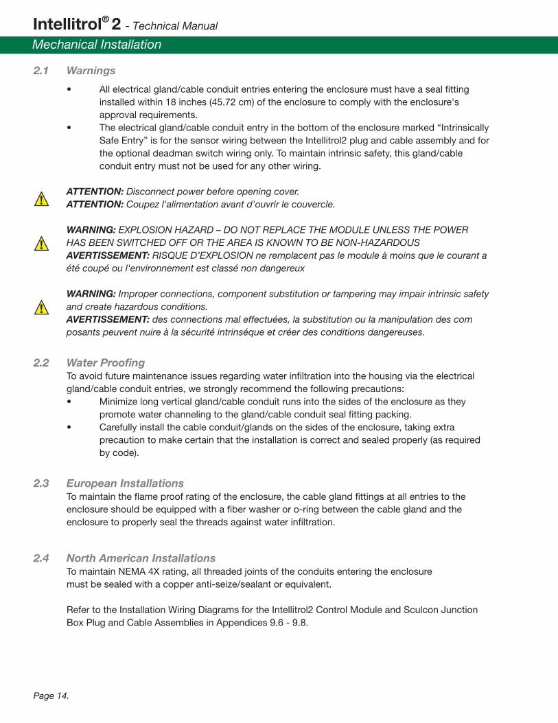
2.1 Warnings
• All electrical gland/cable conduit entries entering the enclosure must have a seal �tting installed within 18 inches (45.72 cm) of the enclosure to comply with the enclosure's approval requirements. • The electrical gland/cable conduit entry in the bottom of the enclosure marked “Intrinsically Safe Entry” is for the sensor wiring between the Intellitrol2 plug and cable assembly and for the optional deadman switch wiring only. To maintain intrinsic safety, this gland/cable conduit entry must not be used for any other wiring.
ATTENTION: Disconnect power before opening cover. ATTENTION: Coupez l'alimentation avant d'ouvrir le couvercle.
WARNING: EXPLOSION HAZARD – DO NOT REPLACE THE MODULE UNLESS THE POWER HAS BEEN SWITCHED OFF OR THE AREA IS KNOWN TO BE NON-HAZARDOUS AVERTISSEMENT: RISQUE D’EXPLOSION ne remplacent pas le module à moins que le courant a été coupé ou l'environnement est classé non dangereux WARNING: Improper connections, component substitution or tampering may impair intrinsic safety and create hazardous conditions. AVERTISSEMENT: des connections mal effectuées, la substitution ou la manipulation des com posants peuvent nuire à la sécurité intrinséque et créer des conditions dangereuses.
2.2 Water Proo�ng To avoid future maintenance issues regarding water in�ltration into the housing via the electrical gland/cable conduit entries, we strongly recommend the following precautions: • Minimize long vertical gland/cable conduit runs into the sides of the enclosure as they promote water channeling to the gland/cable conduit seal �tting packing. • Carefully install the cable conduit/glands on the sides of the enclosure, taking extra precaution to make certain that the installation is correct and sealed properly (as required by code).
2.3 European Installations To maintain the �ame proof rating of the enclosure, the cable gland �ttings at all entries to the enclosure should be equipped with a �ber washer or o-ring between the cable gland and the enclosure to properly seal the threads against water in�ltration.
2.4 North American Installations To maintain NEMA 4X rating, all threaded joints of the conduits entering the enclosure must be sealed with a copper anti-seize/sealant or equivalent.
Refer to the Installation Wiring Diagrams for the Intellitrol2 Control Module and Sculcon Junction Box Plug and Cable Assemblies in Appendices 9.6 - 9.8.
!
!
!

Over�ll Prevention Control Unit (with Automatic Ground Veri�cation & Vehicle Identi�cation Option)
Electrical Installation
Page 15.
3.1 Non-Intrinsically Safe (IS) Connections All Non-IS connections are at the top of the control module and must never be intermixed with IS wiring.
3.1.1 Power Selection The Intellitrol2 is �eld selectable for either 120 or 230 VAC by setting red jumper(s) J10 and J11 at the top of the board. • 120 VAC, Insert 2 horizontal jumpers, one in J10 and one in J11 • 230 VAC, Insert a single vertical jumper between J10 and J11 Note: Refer to Appendix 9.10. See J10 and J11 con�gurations.
3.1.2 Ground It is imperative to Intrinsic Safety that the unit be connected to earth ground. A green terminal block (TB1) is located at the top left of the control module to terminate an incoming ground connection. Do not modify the other connections on this terminal block. • TB1-1, Green wire door ground • TB1-2, Green wire box ground • TB1-3, AC power ground • TB1-4, Extra AC power ground
3.1.3 AC Power Connection • TB2-1, Neutral • TB2-2, Hot
3.1.4 Switched Outputs Powered • TB2-3, Power in • TB2-4, Power out
These connections are used internally to monitor relay status and use a normally open switch for line voltage use.
Caution: Must be the same phase as the power in. Must not be used for low voltage DC switching.
Unpowered • TB3-1, Normally Open (NO) • TB3-3, Normally Closed (NC) • TB3-2, Common (COM)
This set of dry Single Pole Double Throw (SPDT) relay contacts are available for connection of low voltage devices. In the event of a failure all switched power and the NO connections of the unpowered output will fail safe. The NC contact of the unpowered output will remain closed should power be lost and is not fail safe. The NC contact should NOT be used for safety related functions.

Intellitrol® 2 - Technical Manual
Electrical Installation
Page 16.
3.1.5 Ground Permit or Truck Connected Status Output
NOTE: The Ground Permit or Truck Connect is not a Faylsafe output. A single point fault can cause this output to fail.
• TB3-6, is the switched input • TB3-5, Should be connected to the ground of the power supply supplying the switch input TB3-6, and NOT the Intellitrol2 power supply.
TB3-5 and TB3-6 are the terminal connections for the “Ground Permit” or “Truck Connected” output. This output, which is the transistor output of an optoisolator, conducts when a good ground is detected or if a truck is connected to the Intellitrol2, depending on the con�guration. A jumper on J5 of the CPU PCB of the control module con�gures this output to operate either as a “Ground Permit” or “Truck Connected” output (see section 4.1).
This fully isolated output is designed to provide a control logic level signal to a Programmable Logic Controller (PLC) or a Solid State Relay. This output is capable of sinking up to 5 mA (milliamp). When the optoisolator is in the ON or conducting state, the maximum saturation voltage at rated current is 0.4 VDC. In the non-conducting or OFF state, the transistor is capable of withstanding up to 25.2 VDC. If the fuse opens the Intellitrol2 module will have to be returned for repair! This repair is not covered under the warranty.
NOTE: TB3-5 should be connected to the ground of the PLC or solid state relay power supply, NOT to the Intellitrol2 ground!
The output TB3-6 is capable of providing enough current sinking capability to drive SOME low-current Solid State Relays. Some examples of both applications will be illustrated below. The circuit diagram is shown in Figure 3, for reference.
!
!
Figure 3
TB3TerminalNumbers
FUSE
OPTOISOLATOR
6
5

Over�ll Prevention Control Unit (with Automatic Ground Veri�cation & Vehicle Identi�cation Option)
Electrical Installation
Page 17.
!
Some typical wiring diagrams to interface the “Ground Permit” or “Truck Connected” output to a Programmable Logic Controller’s (PLC) input channel (Figure 4) or a Solid State Relay (SSR) is shown in Figure 5.
Figure 5, below, indicates a typical connection from TB3-5 and TB3-6 to an external Solid State Relay (SSR), powered by an external Relay Power Supply (+24 VDC). This external Relay Voltage may be provided by the PLC, or it may be a stand-alone power supply. An appropriate Load Power Source (AC or DC) should be selected to power the appropriate Load (AC or DC).
Some Solid State Relays (SSR) by different manufacturers can also be used. Typical, among these are the CRYDOM ED24C series. These choices are made to insure reliable operation of the Solid State Relays (SSR) by the Intellitrol2’s optoisolator, even with the current limiting resistor and the protective fuse in series with the optoisolator output transistor.
NOTE: DO NOT USE ELECTROMECHANICAL RELAYS. Typically, electromechanical relays draw a higher current than the 5 mA (MAX) that this output will safely provide.
Figure 4
Figure 5
TB3
+5 VDC
PLC
R> 5K Ohms
Buffer
Logic Input Channelwith built-in
pull up resister
6
5{ TB3
10K Ohms
+5 VDC
PLC
(–)
(+)
(–)
(+)CMOSLogicInput
Channel
6
5{ TB3
10K Ohms
+5 VDC
PLC
A to DInput
Channel
6
5{
TB3
Labeled Line
Labeled LoadGEM Safe-Pak Model 22445
Scully P/N 25542
Labeled“Switch”
6
5{Line In
Neutral
Mains120 VAC
Load120 VAC5A Max.
TB3TerminalNumbers
LOAD
1
2
3N+ LoadN- Load
-24VOC
CRYDOM ED24C3 or 5
4
LoadPowerSourceFUSE
OPTOISOLATOR
6
5

Intellitrol® 2 - Technical Manual
Electrical Installation
Page 18.
In any case, the voltage drop across the internal resistor and fuse must be factored into the selection of any appropriate load to be attached. At a maximum allowed current of 5 mA., the voltage lost in the Intellitrol2 optoisolator output circuit will be equal to the current through the selected relay times 85 Ohms plus 0.4 VDC. This loss will occur if a Solid State Relay is connected.
The operating voltage for the connected load should be chosen to assure that:
(Relay Supply Voltage) – (TB3 voltage) > minimum turn on voltage and
(Relay Supply Voltage) – (required relay current X 85 Ohms) > minimum turn on voltage.
In any case, the open circuit control voltage for the relay MUST NOT EXCEED 25 VDC and the MAXIMUM SINK CURRENT MUST NOT EXCEED 5 mA. If the output is interfaced to a low voltage (typ +5 VDC) Programmable Logic Controller (PLC), none of these maximum conditions should present any problems. The pull-up resistors should be at least 5,000 ohms.
Please contact Scully Signal Application Engineering for assistance with any interface requirements or questions not covered by this section.
3.1.6 RS485 Communications Terminal • TB5-1, ground terminal • TB5-2, (TD/RD) “B” terminal • TB5-3, (TD/RD) “A” terminal
Remote communications are available through connector TB5. Appendix 9.9 shows a typical Intellitrol2 multi drop communications wiring scheme for connection details. While it is possible for an Intellitrol2 to share a RS-485 communications line with other equipment, we recommend a dedicated RS-485 communications line to simplify troubleshooting.
3.2 Intrinsically Safe (IS) Connections Caution: DO NOT RUN WIRES connected to Intrinsically Safe connections next to Non Intrinsically Safe wires or connections. Doing so creates risk and an explosion may occur under adverse conditions.
All Intrinsically Safe (IS) connections are made through connectors TB4 and TB6 at the bottom of the box. Connections from TB4 are typically wired one-to-one from the Intellitrol2 to the terminal block in the Sculcon box. Different cable con�gurations are required for connection to 2-wire or 5-wire trucks.

Over�ll Prevention Control Unit (with Automatic Ground Veri�cation & Vehicle Identi�cation Option)
Electrical Installation
Page 19.
!
3.2.1 Sculcon Junction Box Plug and Cable Assembly The Sculcon Junction Box is the preferred way to connect to the IS-Interface. Refer to Appendix 9.3 for the typical Sculcon junction box outline diagram showing physical dimensions, location of mounting bolts and gland/cable conduit entry location details. Refer to Appendices 9.6 - 9.8 for wiring diagrams showing the interconnection details for the Sculcon junction box plug and cable assembly to the Intellitrol. 3.2.2 EN13922 Sensor Wiring Connections • Both 2-wire and 5-wire trucks connect through a 10-pin plug and 10-pin connector (per EN13922)
3.2.3 API Sensor Wiring Connections • 2-wire trucks use an 8- or 10-pin connector with 4 J-Slots on a 10-pin cable. • 5-wire trucks use a 6-pin connector with 3 J-Slots on a 6-pin cable wired to the same connection. Table 1 below describes the connections and function of TB4, Pins 1-10.
3.2.4 Deadman Control • TB6-3, Normally Open (NO), Deadman Switch Input • TB6-4, Return
This Normally Open (NO) connection can optionally be used for a Deadman (switch closure) input signal.
3.2.5 J1 Front Display Panel Connection J1 is located at the bottom left corner of the control board. J1 is a 6-pin ribbon header that provides an IS connection from the controller to the Front Display Panel.
CAUTION: Make sure to note the orientation of this connector before removing. ATTENTION: Assurez-vous de noter l'orientation de ce connecteur avant la dépose.
ConnectionPin Number 1 2 3 4 5 6 7 8 9 10
Terminal Number 1 2 3 4 5 6 7 8 9 10
TB4 Pins
Connection Sculcon Junction Box & Cable Plug Pin / Socket Receptable
2-Wire8 Compartment
2-Wire6 Compartment
5-Wire12Compartment
Sensor1
Sensor2
Sensor3
Sensor4
Sensor5
Sensor6
Sensor1
Sensor2
Sensor3
Sensor4
Sensor5
Sensor6
Sensor7
Sensor8
GND/TIM
Verify
GND
GND/TIM
Verify
GND
GND/TIM
Verify
Pulseto
Sensors
Pulsefrom
Sensors
Powerto
Sensors
GNDDiag.

Intellitrol® 2 - Technical Manual
Electrical Installation
Page 20.
3.3 EMI Shield Kit Installation Instructions In order to minimize Electro Magnetic Interference (EMI), ferrite �lters need to be installed on the three access cables entering the Intellitrol2 Controller. To reduce susceptibility to external EMI, the snap-on ferrite �lters should be installed after the wiring connections are completed inside the Intellitrol2 . Make sure to leave only enough wire near the connectors to accommodate the snap-on ferrites. Simply snap one EMI �lter over all of the wires exiting the control box in all three locations shown.
Control Module: 1. Power in is on the left side 2. Control out/Modbus is on the right side 3. I.S. wiring is at the bottom
KEEP ALL LEADS AS SHORT AS POSSIBLE
61649 RevB

Over�ll Prevention Control Unit (with Automatic Ground Veri�cation & Vehicle Identi�cation Option)
System Setup
Page 21.
1 - 2 TB3-5/6 CONFIG Con�gures TB3 Pins 5-6 to indicate Good Ground (installed) or Truck Present (open)3 - 4 DEADMAN ENABLE Enable Deadman Switch Input5 - 6 DEADMAN DISABLE Disable Deadman Switch Input7 - 8 VAPOR ENABLE Not Used9 - 10 VAPOR DISABLE Not Used11 - 12 VIP ENABLE Enable Vehicle Identi�cation Proving13 - 14 VIP DISABLE Disable Vehicle Identi�cation Proving15 - 16 GND ENABLE Enable Ground Proving17 - 18 GND DISABLE Disable Ground Proving19 - 20 ADD KEY S/N Add Bypass Key Serial Number21 - 22 NORMAL OPERATION Normal Operation23 - 24 ERASE KEY LIST Erase Bypass Key Serial Number List
J5 Function Name Description
4.1 CPU Jumper Settings The Intellitrol2 has a number of features and functions that can be enabled through internal jumper settings. The jumpers on the CPU board are listed below.
4.1.1 Jumper Selectable Options • J5 OPERATING MODE SETTINGS (see 4.1.2) • J8 & J1 COMM MODBUS ADDRESS (see 4.1.3) • J7 COMM PROTOCOL (see 4.1.4)
4.1.2 J5, OPERATING MODE SETTINGS Enable/Disable (purchased options only). Moving the jumper for a non-purchased option to the enable position will have no effect.
Note: The last three jumpers control Enrolling Bypass Key serial numbers into the Intellitrol2’s nonvolatile memory. Refer to Section 4.3 for more detail.
4.1.3 J1 & J8, COMM MODBUS ADDRESS Setting communications speeds and feeds Two sets of jumpers are used for setting the Modbus address. Jumper J8 sets the tens group and jumper J1 sets the ones group. The Modbus address is the sum of the two jumpers.
4.1.4 J7, COMM PROTOCOL RS485 (J7 Jumper Setup) • J7, allow the user to select: - Parity, (NONE/ODD/EVEN) - Baud Rate, (1.2, 2.4, 4.8, 9.6, 19.2 KB/S) - Data Pack, (7 or 8 Bits)

Intellitrol® 2 - Technical Manual
System Setup
Page 22.
Note: Jumper Terminals: Black denotes default installed jumpers, except J5 operating mode settings which are dependent on options purchased.
RESET
Figure 6: CPU Board Layout

Over�ll Prevention Control Unit (with Automatic Ground Veri�cation & Vehicle Identi�cation Option)
System Setup
Page 23.
4.1.5 Control Board Jumper Settings Several modes can be selected using jumpers on the main Control Board.
Note: Refer to Appendix 9.9 for jumper locations on the Intellitrol2 Control Module.
CHANNEL, (Number of Compartments) • J31, Blue - Sets 6 channel mode for 2-wire Sensors • J32, Blue - Sets 8 channel mode for 2-wire Sensors
GND BOLT/BALL OR AUTOMATIC GROUND TYPE DETECTION (Type of ground system check) • J8, Black - Inserted sets automatic ground type detection; otherwise ground bolt/ground ball
THRESHOLD • J4, Black - Inserted sets thermistor threshold = 3.8V for SP-BLK & BLUK type sensors; otherwise thermistor threshold = 3.5V SP-BL & BLU type sensors. (Default for ICC systems is the jumper inserted.)
JUMP START • J21, 22 and 23, Red - Inserted disables Jump Start, limiting IS output voltage for ATEX applications. All three MUST always be in for ATEX installations. Otherwise remove the three jumpers to enable Jump Start for installations requiring preheating of thermistor sensors.
4.2 VIP List The VIP feature is optional and must be ordered. Trucks and Tankers can be out�tted with a Truck Identi�cation Module (TIM) that gives the vehicle a unique serial number. These numbers may be stored on the Intellitrol2 in non-volatile RAM so that the information may be passed to a terminal controller that works in conjunction with the Intellitrol system. The serial numbers must be entered into the Intellitrol via the RS-485 communication port.
4.3 Bypass Key, Add/Erase Procedures Before use, each Bypass Key must �rst be programmed into the Intellitrol2’s permanent memory. Power must be on.
WARNING: The following procedure must not be performed in a �ammable hazardous environment. The Intellitrol2 door cannot be open while fuel or a tanker carrying �ammable substances is present. AVERTISSEMENT: La procédure suivante ne doit être effectuée dans un in�ammables environnement dangereux. Le Intellitrol2 porte ne peut être ouverte pendant que le carburant ou d'un navire-citerne transportant substances in�ammables est présent.
!

Intellitrol® 2 - Technical Manual
System Setup
Page 24.
4.3.1 Adding Bypass Key entries: 1. Unbolt and open the Intellitrol2 door. Store the bolts in a safe place. 2. Move the "NORMAL" jumper on J5 to the "Add Key S/N" position (refer to Figure 6: CPU Board Layout). 3. Push the "Reset" button (top center of CPU board). 4. Close the door and wait for both Optic Pulse and Communications to blink together continuously at double the Dynacheck rate. The Intellitrol2 is now ready for entering a bypass key serial number. 5. Position a bypass key up to the bypass port. The Intellitrol2 will read the bypass key serial number incrementing the "Compartment Number" LED. After all 8 compartment LED's light up, the large green permissive light will �ash brie�y to indicate that the bypass key serial number has been stored in memory. 6. To add additional bypass keys, repeat Step 5 above. When all bypass key serial numbers have been added, proceed to Step 7. 7. Open the Intellitrol2 door and return the jumper on J5 to the "NORMAL" position. 8. Push the "Reset" button. 9. Close and properly secure the Intellitrol2 door using the original bolts. 4.3.2 Erasing Bypass Key entries: It may at some point be necessary to delete the list of "authorized" Bypass Key serial numbers stored within the Intellitrol2's permanent memory (i.e. if a Bypass Key is lost). To delete the list of "authorized" Bypass Keys, do the following:
WARNING: The following procedure must not be performed in a �ammable hazardous environment. The Intellitrol 2 door cannot be open while fuel or a tanker carrying �ammable substances is present. AVERTISSEMENT: La procédure suivante ne doit être effectuée dans un in�ammables environnement dangereux. Le Intellitrol2 porte ne peut être ouverte pendant que le carburant ou d'un navire-citerne transportant substances in�ammables est présent.
Caution: All bypass key entries will be erased.
1. Unbolt and open the Intellitrol2 door. Store the bolts in a safe place. 2. Move the "NORMAL" jumper J5 to the "ERASE_KEY" position (refer to Figure 6: CPU Board Layout). 3. Push the "Reset" button (top center of CPU board). 4. The large red non-permissive indicator will �ash brie�y and the Compartment, Optic Pulse, and Communication LED's will blink at double the Dynacheck rate to indicate that all bypass key entries have been deleted from memory. 5. Return the jumper on J5 to the "NORMAL" position. 6. Push the "Reset" button. 7. Close and properly secure the Intellitrol2 door using the original bolts.
4.3.3 External Bypass key entry/deletion Bypass key serial numbers may be added or deleted one by one from the Intellitrol2 remotely via external software through the communications port.
!

Over�ll Prevention Control Unit (with Automatic Ground Veri�cation & Vehicle Identi�cation Option)
Initial Systems Check
Page 25.
Performing an Initial System Check is essential and proves that the Intellitrol2 installation is performing safely and correctly.
5.1 Inspect Wiring 1. All electrical gland/cable conduit entries must have a seal �tting installed within 18 inches (45.72 cm) of the enclosure to comply with approval requirements. 2. The electrical gland/cable conduit entry in the bottom of the enclosure marked “Intrinsically Safe Entry” is for the sensor wiring between the control unit plug and cable assembly and for the optional deadman switch wiring only. To maintain intrinsic safety, this gland/cable conduit entry must not be used for any other wiring. 3. Inspect all �eld wiring for neat professional installation, and adherence to all wiring instructions above. Verify that all wiring terminals are tightened securely by tugging on each connection. Close the control unit's cover and fasten securely. Tighten the cover bolts in a criss-crossing pattern.
5.2 Recommended Test Equipment While use of Scully Signal Company test equipment is not required, It is recommended. The test equipment provides all of the proper over�ll prevention system signals required to verify the new installation without requiring actual vehicles for the testing.
5.3 Scully Rack Tester Model 09832 The Scully Rack Tester is a portable, self-contained device which incorporates a number of switches, connectors, and all required circuitry necessary to simulate 2-wire optical, 5-wire optical, and thermistor sensors, ground, and TIM functions required to verify proper Rack operation. The Scully Rack Tester is designed with intrinsically safe outputs and is certi�ed to operate in Division I and Zone 0 hazardous locations. The use of this tester is much like the ST-2-DSWJ with switches replacing buttons and including optical 2-wire sensors in addition to thermistors. A notable difference is the Intellitrol2 light indicators match the tester switch numbers in an 8 compartment con�guration. In a 6 compartment con�guration, switch 3 matches indicator 1.
5.4 Model ST-2-DSWJ Tester The Model ST-2-DSWJ Tester provides a rotary switch to select the following functional safety checks: • Cable Continuity • Float Switch Detection • Thermistor Sensor Detection • Optical Sensor Detection

Intellitrol® 2 - Technical Manual
Initial Systems Check
Page 26.
5.4.1 Operational Testing Sequence 1. No vehicle or tester connected to Intellitrol2. 2. Power up Intellitrol2. 3. Intellitrol2 will go through a power up sequence, including the testing of all internal functions and operating parameters. 4. Checks and enables display panel LED's in sequence. 5. Red non-permissive indicator will light after 15 seconds. 6. Yellow Dynacheck LED will �ash indicating that the Intellitrol2 is ready to accept a vehicle. If the Intellitrol2 is connected to a terminal automation system, the yellow terminal LED will also �ash each time the Intellitrol2 is polled by the automation system.
5.4.2 Equipment Attachment Set the ST-2-DSWJ tester to Thermistor Sensor Detection mode. Attach the black or green 2-wire thermistor or 2-wire optic plug from the Intellitrol2 to the 2-wire thermistor or 2-wire optic socket (SJ-8S-2 bayonet pin style) on the right side of the housing.
5.4.3 Two-Wire Thermistor Sensor Operation Testing The ST-2-DSWJ tester uses one "Channel Test" button/switch per thermistor sensor and each corresponding sensor will be tested when that button is depressed.
When the tester is attached to the thermistor socket, the Intellitrol2 will detect that it is attached to a “thermistor” equipped vehicle and proceed to warm up the sensors (the tester has traditional thermistor sensors inside). While the sensors are warming up, the 6 (or 8) red compartment indicator lights at the top of the Intellitrol2's diagnostic display panel will light, indicating 6 (or 8) wet sensors. As each thermistor sensor warms up, the red compartment indicator, corresponding to that sensor, will go out indicating a dry sensor. When all of the thermistor sensors are warmed up (up to 75 seconds required) the Intellitrol2 will permit, and the green main status indicator will come on. Verify that the Intellitrol2's main output relay contact has closed (turned on) and that product can be transferred. This can be done by verifying that this permissive signal is available at the product meter(s) external permissive input terminal(s). Some metering systems also have a visible indicator (LED) to indicate that the external permissive signal is satis�ed.
For each thermistor sensor selected, verify that the Intellitrol2 goes non-permissive and shuts down the Rack/Gantry. For a 6 compartment con�guration, the corresponding compartment indicator light on the Intellitrol2 diagnostic display panel will light when the test button/switch is pushed. For an 8 compartment con�guration, the button 3 matches Intellitrol2 indicator 1 and the buttons an indicators follow in sequence from there.If more than one plug (or two different styles of plugs) is used on this installation for 2-wire thermistor or 2-wire optic operation, repeat the above tests for the other plug.

Over�ll Prevention Control Unit (with Automatic Ground Veri�cation & Vehicle Identi�cation Option)
Initial Systems Check
Page 27.
5.4.4 Five-Wire Optic Sensor Operation Testing Set the ST-2-DSWJ tester to Optic Sensor Detection mode. If the installation uses a single plug for both 2-wire thermistor or 2-wire optic and 5-wire optic modes, leave the plug connected as per the above. If the installation uses separate plugs for 2-wire thermistor or 2-wire optic and 5-wire optic operating modes, attach the optic plug from the Intellitrol2 to the optic socket. This will be either the SJ-6W-3 bayonet pin style socket on the left side of the housing for a blue "6W" style optic plug, or the SAE J- 560 style socket on the back of the tester housing for a "6X" style optic plug. When attached to this optic socket, the Intellitrol2 will detect that it is attached to a 5-wire optic equipped vehicle and proceed immediately to permit. The Intellitrol2's diagnostic display panel will light, indicating an "optic out" pulse from the Intellitrol2 and an "optic in" pulse from the tester. As the Intellitrol2 permits, the green main status indicator will light up. Verify that the output to the metering system again turns on and that product can be transferred. Verify that when push-button/switch no. 2, no. 4 or no. 6 on the tester is pushed, the Intellitrol2 goes non-permissive and shuts down product �ow. Compartment indicator light no. 1 on the Intellitrol2 diagnostic display panel will light when one of these tester buttons is pushed.
5.5 Fault Conditions If the Intellitrol2 fails the power up diagnostic test, the Service LED will �ash ON-OFF and the Dynacheck light will be off. After making sure that the Intellitrol2's plug(s) are not connected to a truck, remove power from the unit for 15 seconds and reapply. If this does not correct the problem, refer to the Troubleshooting Chart in Section 7.3. There can not be a vehicle attached to the Intellitrol2 during power-up (or during a reset). If there is a vehicle attached during power-up, the Intellitrol2 will fail its diagnostic tests.
If the Intellitrol2 does not permit the tester in either of the above modes, refer to the diagnostic display panel for speci�c information on identifying the cause of the problem. Most of the detailed instructions and cautions for operation of the Intellitrol2 system and accessories have already been discussed. The basics of loading a vehicle are described below. Refer to Figure 7 for details of the Intellitrol2's main status indicators and diagnostic display panel.
Figure 7: Main Status and Diagnostic Display Panel Indicators
Red (Non-Permissive)Main Status Indicator
Green (Permissive)Main Status Indicator
Wet / Faulty SensorIndicators
Communications Indicators
Bypass Port
Dynacheck Indicator
Ground Error Indicator
5-Wire Optic ModeStatus Indicators
Service IndicatorGood Ground Indicator
OptionalVehicle Identi�cationProver Indicators (VIP)
Out
In
Ground Error
Service
Ground
Terminal
Authorized
Unauthorized
Standby
Vehicle
Communication
Vehicle Identi�cation
Optic Pulse
Dynamic Self-Checking®Dynacheck®
BY
PA
SS
1 2 3 49 10 11 12
5 6 7 8Compartment

Intellitrol® 2 - Technical Manual
System Operation
Page 28.
6.1 Normal Loading The Intellitrol2 is capable of automatically detecting the presence of 2-wire and 5-wire over�ll sensors. In operation it constantly monitors the truck plug while running diagnostics. Once a truck is detected the system determines the sensor type and monitors for dry condition.
Optic sensors are detected within a second. Thermistor sensors must heat up before indicating a dry condition. The heat-up time for thermistor sensors can take up to 75 seconds. This is a normal condition.
6.2 After a Normal Load Disconnect the plug from the vehicle to be loaded. The Intellitrol2 will return to its non-permissive state and the diagnostic display panel will �rst �ash all of the 8 compartment indicators and then clear (go blank) within a few seconds. This indicates that the Intellitrol2's plug is ready to be connected to the next vehicle.
6.3 Intellitrol2 Not Permitting If the Intellitrol2 main display does not go green, the reason for the problem will be indicated in the front panel display (see Section 7.3 Troubleshooting Chart for details). A faulty or unauthorized TIM, a faulty ground condition and wet or faulty compartment sensors at connection time are indicated on the front panel by red LEDs being illuminated. These conditions can be bypassed with the use of a properly registered bypass key.
All indicators will look correct when the non-permit is due to the deadman switch. The deadman cannot be bypassed.
6.4 Bypassing Fault Conditions 6.4.1 Bypassing in General When blinking green the ground or VIP is bypassed or the active deadman switch is nearing the end of its close time and must be opened to prevent a non-permit. The bypass blink is at a slow rate and the LEDs are on for ¾ of the blink, the deadman blink is fast and the on and off times are equal.

Over�ll Prevention Control Unit (with Automatic Ground Veri�cation & Vehicle Identi�cation Option)
System Operation
Page 29.
6.5 Grounding The Intellitrol2 ground detection is dependent on the proper wiring of the vehicle being loaded. This requires that the vehicle rack connection socket have pins 9 and 10 independently connected to the vehicle chassis. Use of a Scully ground bolt, mounted on the vehicle chassis, ensures a good ground connection is in place. When a ground bolt is not used the EN 13922 standard is that pin 9 of the connection socket is connected to the vehicle chassis through the socket mounting bolt and pin 10 is connected to the chassis by hardwiring. It is recommended that a Truck Identi�cation Module (T.I.M.) be used only in conjunction with a ground bolt. To prevent false ground detection through the T.I.M. rather than the ground bolt the automatic ground detection must be turned off by removing J8, or the T.I.M. ground wire must be connected to the chassis separate from the pin 10 connection.
Correct T.I.M. wiring without a ground bolt requires the T.I.M. be connected between pin 9 and the chassis separate from the pin 10 connection to chassis. Only a small amount of resistance in this connection will result in T.I.M. communication failures.
Corrosion and debris are common causes of grounding problems. Connection points to the chassis should be examined and cleaned if necessary to resolve these problems. The socket enclosure may need to be removed for this.

Intellitrol® 2 - Technical Manual
Maintenance
Page 30.
7.1 Preventative Maintenance The Intellitrol2 should be inspected annually. The o-ring and corrosion pack should be replaced at this time. It is recommended that maintenance on Scully equipment be carried out by Scully certi�ed technicians.
7.2 Functional Safety Proof Testing It is a requirement of the Functional Safety certi�cation that periodic proof testing be performed. Refer to the Intellitrol2 Safety Manual for the recommended test methods and frequency.
7.3 Warranty
7.3.1 Intellitrol2 Control Unit The Intellitrol2 Control Unit is warranteed by Scully Signal Company ("Scully") to be free from defects in material and workmanship under normal use and service for a period of three years. Warranty covers manufacturing defects. Damage speci�cally resulting from improper use or incorrect installation is not covered.
7.3.2 General Terms All equipment returned to Scully that has a manufacturing date code that exceeds the warranty period should be accompanied by an invoice or work order that states the date of installation. Under these warranties, Scully shall be responsible only for actual loss or damage suffered and then only to the extent of Scully's invoiced price of the product. Scully shall not be liable in any case for labor charges for indirect, special, or consequential damages. Scully shall not be liable in any case for the removal and/or reinstallation of defective Scully equipment.
These warranties shall not apply to any defects or other damages to any Scully equipment caused by misuse or negligence, and this warranty shall not apply to any Scully equipment that has been altered or tampered with by anyone other than Scully factory representatives. These warranties are the only warranties, expressed or implied, upon which products are sold by Scully, and Scully makes no warranty of suitability for any particular purpose in respect to the products sold.
Scully products or parts thereof assumed to be defective by the purchaser within the stipulated warranty period should be returned to the seller, local distributor, or directly to Scully for evaluation and service. Whenever direct factory evaluation, service, or replacement is necessary, the customer must �rst, by either email or phone, obtain a Returned Material Authorization Number (RMA) from Scully Company directly. No material may be returned without an RMA number assigned to it or without proper factory authorization.
Any returns must be returned freight prepaid to: Scully Signal Company, 70 Industrial Way Wilmington, MA 01887 U.S.A., Attention: Service Dept. Returned warranty items will be repaired or replaced at the discretion of the Scully Service Department according to Scully Product Warranty Policy and the Scully Returned Materials Procedure. Any Scully items under the Scully Warranty Policy that are deemed not repairable by the Scully Service Department will be replaced at no charge or a credit issued for that item subject to the customer's request.

Over�ll Prevention Control Unit (with Automatic Ground Veri�cation & Vehicle Identi�cation Option)
Maintenance
Page 31.
7.4 Troubleshooting Guide If the front panel Dynacheck LED is not �ashing, with other LEDs illuminated, it likely there is a problem with the module assembly power. The diode pack (heat sink assembly) in the rear of the Intellitrol2 housing should be veri�ed before replacing/installing any new or refurbished module.
7.4.1 Checking the Diode Pack Using a multimeter on the diode setting, measure from the tip of each blue wire to the screws where the black wires are mounted. Correct readings should be ~ .50 - .60 (diode scale) with the red lead on the screws and the black lead on the blue wire. With the leads reversed it should read as an open.
If the reading indicates a short, the diodes in the component are faulty and the pack itself will require replacement. This must be replaced before installing a new or refurbished module. Failure to replace the diode pack WILL result in damage to any module installed.
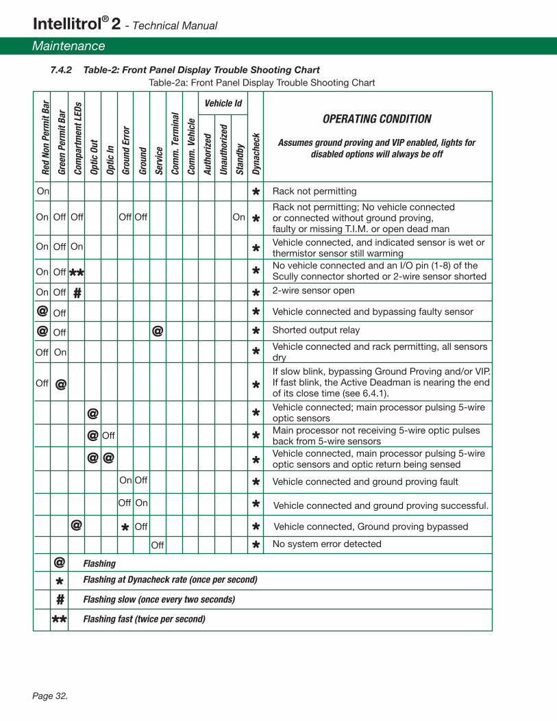
The following table summarizes errors indicated via the front panel and their most likely causes. Problems covered are the: • Intellitrol2 Self Check failure • Unit's plug and cable assembly(s) • Vehicle trying to get a permissive signal to load at the rack. This chart and the troubleshooting guide should be consulted prior to requesting technical service help. If after consulting the chart you are unable to resolve the problem contact Scully Technical Services at 1-800 Scully and be prepared to communicate the status of the indicators on the front panel.
WARNING: Certain checks may require access to the inside of the control unit to verify or change con�guration jumpers. Any activity requiring the opening of the unit should only be performed by quali�ed personnel. The area must be secured and vapor free before opening the enclosure to avoid explosion. AVERTISSEMENT: Certains contrôles peuvent exiger l'accès à l'intérieur de l'unité de contrôle pour véri�er ou modi�er les cavaliers de con�guration. Toute activité nécessitant l'ouverture de l'appareil ne doit être effectué par du personnel quali�é. La zone doit être �xé et la vapeur libre avant d'ouvrir le boîtier pour éviter l'explosion.
!
Intellitrol® 2 - Technical Manual
Maintenance
Page 32.
Rack not permitting
@
@
@
@
@
@ @
@
*#
#
**
**
Red
Non
Perm
it Ba
r
Gree
n Pe
rmit
Bar
Com
part
men
t LED
s
Optic
Out
Optic
In
Grou
nd
Grou
nd E
rror
Serv
ice
Com
m. T
erm
inal
Com
m. V
ehic
le
Auth
oriz
ed
Unau
thor
ized
Stan
dby
Vehicle Id
OPERATING CONDITION
Assumes ground proving and VIP enabled, lights fordisabled options will always be off
Dyna
chec
k
Flashing
Flashing at Dynacheck rate (once per second)
Flashing slow (once every two seconds)
Flashing fast (twice per second)
7.4.2 Table-2: Front Panel Display Trouble Shooting Chart Table-2a: Front Panel Display Trouble Shooting Chart
On
On On
On On
On
On
OnOff
Off
On
Rack not permitting; No vehicle connectedor connected without ground proving,faulty or missing T.I.M. or open dead manVehicle connected, and indicated sensor is wet orthermistor sensor still warmingNo vehicle connected and an I/O pin (1-8) of theScully connector shorted or 2-wire sensor shorted
2-wire sensor open
Vehicle connected and bypassing faulty sensor
Vehicle connected and rack permitting, all sensorsdry
If slow blink, bypassing Ground Proving and/or VIP.If fast blink, the Active Deadman is nearing the endof its close time (see 6.4.1).
Vehicle connected; main processor pulsing 5-wireoptic sensorsMain processor not receiving 5-wire optic pulsesback from 5-wire sensorsVehicle connected, main processor pulsing 5-wireoptic sensors and optic return being sensed
Vehicle connected and ground proving fault
Vehicle connected and ground proving successful.
Vehicle connected, Ground proving bypassed
No system error detected
Off
Off
Off
Off
Off
OffOn
Off
Off
Off OffOff
Off
Off
**
****
@ @ Shorted output relayOff **
*
********

Over�ll Prevention Control Unit (with Automatic Ground Veri�cation & Vehicle Identi�cation Option)
Maintenance
Page 33.
Table-2b: Front Panel Display Trouble Shooting Chart
Terminal communications line error
Red
Non
Perm
it Ba
r
Gree
n Pe
rmit
Bar
Com
part
men
t LED
s
Optic
Out
Optic
In
Grou
nds
Serv
ice
Com
m. T
erm
inal
Com
m. V
ehic
le
Auth
oriz
ed
Unau
thor
ized
Stan
dby
Vehicle Id
OPERATING CONDITION
Assumes ground proving and VIP enabled, lights fordisabled options will always be off
Dyna
chec
k
Flashing
Flashing at Dynacheck rate (once per second)
Flashing slow (once every two seconds)
Flashing fast (twice per second)
On
On
On
On
On
Intellitrol2 not communicating with terminal
Intellitrol2 communicating with terminal
Vehicle communications error
Vehicle not connected/not communicating
Intellitrol2 communicating with the vehicle
Vehicle connected, T.I.M. good, and authorized
Vehicle connected, VIP bypassed
Vehicle connected, T.I.M. good but notunauthorized, i.e. ID not in VIP list
Vehicle not connected, or unable to read T.I.M.s
Intellitrol 2 with VIP operational
With vehicle connected, unable to see T.I.M.s
Intellitrol 2 without VIP operational
Unrecoverable system error occurred
No Power; front panel bad/not connected
All other displays = bad front panel or unit
Off
Off
Off Off
Off
Off
Off
Off
Off
Off Off
Off
Off Off Off Off Off Off Off Off Off Off Off Off Off
Off
@
*
* **************
**
#
**Compartments 7 & 8 Flashing
@***
System error detected. Compartment LEDs7 & 8 �ashing indicates EEPROM or programmemory error.
*
***

Intellitrol® 2 - Technical Manual
Maintenance
Page 34.
7.5 Installing Replacement Parts Warning: Opening the Intellitrol2 exposes Non-Intrinsically safe circuits to the atmosphere. Always assure the location is secured and is non-hazardous before opening an explosion proof housing. l'ouverture du Intellitrol2 expose Non-Intrinsically circuits de sécurité dans l'atmosphère. Toujours assurer l'emplacement est sécurisé et est non dangereux avant d'ouvrir une explosion boîtier étanche
The Intellitrol2 contains only three �eld replaceable modules. Order a replacement with the correct part number corresponding to the options purchased.
• Control Module • Front Panel display • Heat Sink Assembly
7.5.1 Control Module Replacement Procedure • Disconnect the unit from power • Unbolt and open the Intellitrol2 door • Unplug all connectors, noting orientation of J1 ribbon to front panel • Remove all ground wires from the TB1 terminal block • Loosen the four captive screws in the corners of the module and remove the wires on the bottom of the module connecting to the heat sink assembly. • Re-assemble in reverse direction
Warning: The blue and black wires from the IS Barrier Heat sink assembly are an integral part to safety and MUST all be reconnected to assure continued Intrinsic Safety! les �ls bleu et noir de la barrière est assemblage du dissipateur de chaleur sont une partie intégrante de la sécurité et doivent toutes être reconnecté à garantir la poursuite sécurité intrinsèque !
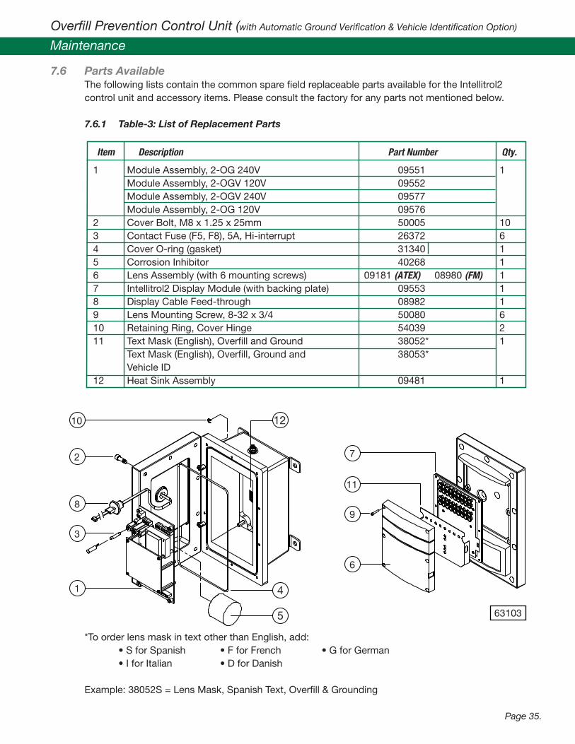
7.5.2 Front Panel Display Module Replacement • Remove power from the unit • Refer to drawing 63103 in section 7.5.1 for the next steps - Remove the 6 screws from the Lens assembly - Remove the panel assembly (items 6, 7 and 11) being careful not to lose the nylon washers between the backing plate and cover (washers not shown in drawing) - Disconnect the connector at the back of the panel assembly noting the orientation - Re-assemble in reverse direction
!
!
Over�ll Prevention Control Unit (with Automatic Ground Veri�cation & Vehicle Identi�cation Option)
Maintenance
Page 35.
7.6 Parts Available The following lists contain the common spare �eld replaceable parts available for the Intellitrol2 control unit and accessory items. Please consult the factory for any parts not mentioned below. 7.6.1 Table-3: List of Replacement Parts
*To order lens mask in text other than English, add: • S for Spanish • F for French • G for German • I for Italian • D for Danish
Example: 38052S = Lens Mask, Spanish Text, Over�ll & Grounding
Item Description Part Number Qty.
1 Module Assembly, 2-OG 240V 09551 1 Module Assembly, 2-OGV 120V 09552 Module Assembly, 2-OGV 240V 09577 Module Assembly, 2-OG 120V 09576 2 Cover Bolt, M8 x 1.25 x 25mm 50005 103 Contact Fuse (F5, F8), 5A, Hi-interrupt 26372 64 Cover O-ring (gasket) 31340 15 Corrosion Inhibitor 40268 16 Lens Assembly (with 6 mounting screws) 09181 (ATEX) 08980 (FM) 17 Intellitrol2 Display Module (with backing plate) 09553 18 Display Cable Feed-through 08982 19 Lens Mounting Screw, 8-32 x 3/4 50080 610 Retaining Ring, Cover Hinge 54039 211 Text Mask (English), Over�ll and Ground 38052* 1 Text Mask (English), Over�ll, Ground and 38053* Vehicle ID12 Heat Sink Assembly 09481 1
10
2
8
3
1 4
5
12
7
11
9
6
63103

Technical Service Hot-Line / Notes
Intellitrol® 2 - Technical Manual
Maintenance
Page 36.
Technical Service Hot-Line Scully's Technical Service Department can be reached at the corporate headquarters in Wilmington, MA U.S.A. by telephone at (617) 692-8602; by FAX at (617) 692-8620; and by email at [email protected]. If calling from within the United States, our toll free Technical Service Hot-Line Number is (800) 272-8559.
Our technical service department staff is available from 8 AM to 5 PM Eastern Standard Time to answer any questions which may arise regarding the installation, operation or service of the Scully Intellitrol2 and accessories.
Notes
7.6.2 Table-4: List of Accessories
08939 Bypass Key Authorizer08863 Deadman Control Switch Assembly08951 Intelliview® 2 Terminal Software09001 RS-232 to RS-485 Converter Kit (for communications)08958 SC-8OB Sculcon Junction Box with 8B Style Black Poly Plug and 6 meter (20 ft) Blue Straight Cable (for 2-wire or 5-wire sensors - 4-bayonet pins - 10 contact pins)08959 SC-8B Sculcon Junction Box with 8B Style Green Poly Plug and 6 meter (20 ft) Blue Straight Cable (for 2-wire or 5-wire sensors - 4 bayonet pins - 10 contact pins)08729 SC-8A Sculcon Junction Box with 8A Style Green Poly Plug and 9 meter (30 ft) Orange Coiled Cable (for 2-wire sensors - 2 bayonet pins - 10 contact pins)08156 SC-6A Sculcon Junction Box with 6A Style Green Poly Plug and 9 meter (30 ft) Orange Coiled Cable (for 2-wire sensors - 2 bayonet pins - 8 contact pins)08159 SC-6W Sculcon Junction Box with 6W Style Blue Poly Plug and 9 meter (30 ft) Blue Coiled Cable (for 5-wire sensors - 3 bayonet pins - 6 contact pins)
Part Number Description

Over�ll Prevention Control Unit (with Automatic Ground Veri�cation & Vehicle Identi�cation Option)
Diagram Appendix
Page 37.
9.1 Dwg. No. 63038C – Intellitrol Enclosure Outline, Model Series ICC
235.
0 M
M
FOR
I.S
. SE
NS
OR
WIR
ING
ON
LYM
25 X
1.5
(IS
O) M
ETR
IC
MO
UN
TIN
G B
OLT
CE
NTE
RS
FOR
8 M
M D
IA. B
OLT
S
177.
8 M
M
43.2
MM
181.
0 M
M
212.
8 M
M
INTR
INS
ICA
LLY
EN
TRY
SA
FE
85.8
MM
212.
8 M
M
EN
CLO
SU
RE
EA
RTH
BO
ND
ING
STU
D
Aut
omat
ic &
Con
tinuo
us S
elf-
Che
ckin
g
4
RD
ynac
heck
Op
tic P
ulse
Ser
vice
Gro
und
In
32
1
Out
R
Com
mun
icat
ion
7
Term
inal
Vehi
cle
65
8
Com
par
tmen
t
347.
7 M
M
85.8
MM
63.5
MM
FOR
PO
WE
R A
ND
CO
NTR
OL
WIR
ING
M25
X 1
.5 (I
SO
) ME
TRIC
PO
RT
63.5
MM
85.8
MM
CO
MM
UM
ICAT
ION
S W
IRIN
GFO
R A
DD
ITIO
NA
L O
UTP
UT
&M
25 X
1.5
(IS
O) M
ETR
IC P
OR
T
6303
8C R
evD

Intellitrol® 2 - Technical Manual
Diagram Appendix
Page 38.
9.2 Dwg. No. 63038 – Intellitrol Enclosure Outline, Model Series IC
6303
8 R
evD
FOR
I.S. S
ENSO
R W
IRIN
G O
NLY
3/4-
14 N
PT C
ON
DU
IT P
ORT
MO
UN
TIN
G B
OLT
CEN
TERS
FOR
3/8
- IN
CH D
IA. B
OLT
S
COM
MU
MIC
ATIO
NS
WIR
ING
FOR
AUX.
OU
TPU
TS &
3/4-
14 N
PT C
ON
DU
IT P
ORT
3/4-
14 N
PT C
ON
DU
IT P
ORT
POW
ER A
ND
CO
NTR
OL
WIR
ING
8.38
7.13
Term
inal
Out
9.25
7.00
1.70
SAFE
ENTR
Y
INTR
INSI
CALL
Y
8.38
Vehi
cle
Auto
mat
ic &
Con
tinuo
us S
elf-
Chec
king
In Gro
und
Serv
ice
Dyn
ache
ckR
R
BON
DIN
G S
TUD
ENCL
OSU
RE E
ART
H
3.38
2.50
Com
part
men
t
51
23
Opt
ic P
ulse
48
67
Com
mun
icat
ion
3.3813
.69
3.38
2.50

Over�ll Prevention Control Unit (with Automatic Ground Veri�cation & Vehicle Identi�cation Option)
Diagram Appendix
Page 39.
6303
9 R
evF
9.3 Dwg. No. 63039 – Sculcon Plug and Cable Assembly Outline

Intellitrol® 2 - Technical Manual
Diagram Appendix
Page 40.
9.4 Dwg. No. 61337C – Mech. Installation, Intellitrol Model Series ICC
AD
DIT
ION
AL
OU
TPU
T C
ON
TRO
L&
CO
MM
UN
ICAT
ION
S W
IRIN
G
OV
ER
FILL
PR
EV
EN
TIO
N S
YS
TEM
ON
PLU
G A
SS
EM
BLY
TO
CO
NN
EC
T TO
WIR
ING
US
ING
SE
PAR
ATE
INTR
INS
ICA
LLY
SA
FE
TYP
E-A
CA
BLE
4
Op
tic P
ulse
Ser
vice
Dyn
ache
ck
In Gro
und
1
Out2
Vehi
cle
Aut
omat
ic &
Con
tinuo
us S
elf-
Che
ckin
gR
R
Com
mun
icat
ion
Term
inal
65
34
Com
par
tmen
t
87
3
VE
HIC
LE.
2
MA
INS
PO
WE
R A
ND
OU
TPU
TC
ON
TRO
L W
IRIN
G
3
1
5. A
NY
UN
US
ED
HO
LES
IN T
HE
FLA
ME
PR
OO
F E
NC
LOS
UR
E M
US
T B
E
PLU
GG
ED
US
ING
A C
ER
TIFI
ED
FLA
ME
PR
OO
F S
TOP
PE
R P
LUG
.
AN
D T
HE
INTE
LLIT
RO
L H
OU
SIN
G A
T A
LL C
AB
LE P
OR
T E
NTR
IES
.
4. U
SE
FIB
ER
SE
ALI
NG
WA
SH
ER
S B
ETW
EE
N T
HE
CA
BLE
GLA
ND
FIT
TIN
GS
4. I
ND
US
TRIA
L C
AB
LE G
LAN
D F
ITTI
NG
.
OF
THE
INTE
LLIT
RO
L H
OU
SIN
G T
O A
VO
ID C
ON
DE
NS
ATIO
N C
HA
NN
ELI
NG
.
CA
BLE
OR
IN A
CO
ND
UIT
. NO
OTH
ER
SIG
NA
LS A
RE
TO
BE
RU
N IN
CA
BLE
JU
NC
TIO
N B
OX
MU
ST
BE
RU
N U
SIN
G D
ED
ICAT
ED
TY
PE
-A
OF
THE
INTE
LLIT
RO
L H
OU
SIN
G A
ND
TH
E S
CU
LCO
N P
LUG
AN
D
2. T
HE
INTR
INS
ICA
LLY
SA
FE W
IRIN
G B
ETW
EE
N T
HE
BO
TTO
M P
OR
T
INTE
ND
ED
TO
RE
PR
ES
EN
T C
OD
E C
OM
PLI
AN
CE
.
DE
TAIL
S S
HO
WN
AR
E F
OR
RE
FER
EN
CE
ON
LY A
ND
AR
E N
OT
RE
GU
LATI
ON
S F
OR
INS
TALL
ATIO
NS
IN H
AZ
AR
DO
US
LO
CAT
ION
S
3. M
INIM
IZE
LO
NG
VE
RTI
CA
L R
UN
S O
F C
AB
LE IN
TO T
HE
TO
P P
OR
TS
1. I
NS
TALL
ATIO
N M
US
T C
OM
PLY
WIT
H N
ATIO
NA
L A
ND
LO
CA
L
INS
TALL
ATIO
N N
OTE
S
3. F
LAM
EP
RO
OF
Exd
CA
BLE
GLA
ND
FIT
TIN
G.
THIS
CA
BLE
OR
CO
ND
UIT
.
EQ
UIP
ME
NT
SC
HE
DU
LE (T
YP
ICA
L)
2. S
CU
LCO
N P
LUG
AN
D C
AB
LE U
NIT
.
1. I
NTE
LLIT
RO
L C
ON
TRO
L U
NIT
.
6133
7C R
evD

Over�ll Prevention Control Unit (with Automatic Ground Veri�cation & Vehicle Identi�cation Option)
Diagram Appendix
Page 41.
9.5 Dwg. No. 61337, Mech. Installation, Intellitrol Model Series IC
6133
7 R
evE
COM
MU
NIC
ATIO
NS
WIR
ING
(3/4
" CO
ND
UIT
)
PLU
G A
SSEM
BLY
TO C
ON
NEC
T TO
OVE
RFIL
L PR
EVEN
TIO
N S
YSTE
M O
N
WIR
ING
IN S
EPA
RATE
INTR
INSI
CALL
Y SA
FE
3/4"
CO
ND
UIT
7
Opt
ic P
ulse
Serv
ice
Dyn
ache
ck
Gro
und
In2 Out
1
Vehi
cle
Auto
mat
ic &
Con
tinuo
us S
elf-
Chec
king
RR
6 Term
inal
Com
mun
icat
ion
Com
part
men
t
43
57
8
3
VEH
ICLE
.
2
MA
INS
POW
ER A
ND
OU
TPU
TCO
NTR
OL
WIR
ING
(3/4
" CO
ND
UIT
)
3
1
54
5. A
PPLY
AN
TISE
IZE
/ SEA
LAN
T TO
TH
E CO
ND
UIT
TH
REA
DS
AT A
LL
4. M
INIM
IZE
LON
G V
ERTI
CAL
RUN
S O
F CO
ND
UIT
INTO
TH
E TO
P CO
ND
UIT
PORT
S O
F TH
E IN
TELL
ITRO
L H
OU
SIN
G T
O A
VOID
CO
ND
ENSA
TIO
N.
THRE
AD
ED JO
INTS
TO
PRE
VEN
T W
ATER
INFI
LTRA
TIO
N IN
TO C
ON
DU
IT.
4. E
XPLO
SIO
N P
ROO
F CO
ND
UIT
OU
TLET
BO
DY.
5. C
ON
DU
IT S
EAL
FITT
ING
WIT
H IN
TEG
RAL
DRA
IN.
6. E
XPLO
SIO
N P
ROO
F JU
NC
TIO
N B
OX
(IF R
EQU
IRED
).
7. W
ATER
TIG
HT
IND
UST
RIA
L EN
CLO
SURE
CO
ND
UIT
HU
B.
INST
ALL
ATIO
N N
OTE
S
1. S
EAL
FITT
ING
S M
UST
BE
INST
ALL
ED W
ITH
IN 1
8 IN
CHES
OF
2. I
NST
ALL
ATIO
N M
UST
CO
MPL
Y W
ITH
ALL
FED
ERA
L, S
TATE
THE
INTE
LLIT
ROL
ENCL
OSU
RE.
PLU
G A
LL U
NU
SED
CO
ND
UIT
EN
TRIE
S.
AN
D L
OCA
L RE
GU
LATI
ON
S FO
R IN
STA
LLAT
ION
S IN
HA
ZARD
OU
S
LOCA
TIO
NS.
DET
AIL
S SH
OW
N A
RE F
OR
REFE
REN
CE O
NLY
AN
D
ARE
NO
T IN
TEN
DED
TO
REP
RESE
NT
COD
E CO
MPL
IAN
CE.
3. T
HE
INTR
INSI
CALL
Y SA
FE W
IRIN
G B
ETW
EEN
TH
E BO
TTO
M C
ON
DU
IT
PORT
OF
THE
INTE
LLIT
ROL
HO
USI
NG
AN
D T
HE
SCU
LCO
N P
LUG
AN
D C
ABL
E JU
NC
TIO
N B
OX
MU
ST B
E RU
N IN
DED
ICAT
ED C
ON
DU
IT.
NO
OTH
ER C
ON
DU
CTO
RS A
RE T
O B
E RU
N IN
TH
IS C
ON
DU
IT.
6
1. I
NTE
LLIT
ROL
CON
TRO
L U
NIT
.
2. S
CULC
ON
PLU
G A
ND
CA
BLE
UN
IT.
3. E
XPLO
SIO
N P
ROO
F CO
ND
UIT
UN
ION
.
EQU
IPM
ENT
SCH
EDU
LE (T
YPIC
AL)
DEA
DM
AN

Intellitrol® 2 - Technical Manual
Diagram Appendix
Page 42.
9.6 Dwg. No. 61335C – (2-Wire, Optic or Therm.) Sculcon Field Wiring Diagram
6133
5C R
evC
STA
ND
ARD
EN
500
39 (S
EE N
OTE
1).
NO
CO
NN
ECTI
ON
MA
IN C
ON
TRO
L O
UTP
UT
- A.C
.
250
VAC,
5A
RES
ISTI
VE M
AX.
OU
TPU
T SI
GN
AL
ON
PER
MIS
SIVE
JUN
CTI
ON
BO
XSC
-8O
B/8B
SCU
LCO
N
TYPE
-A C
ABL
E PE
R EU
ROPE
AN
(SEE
NO
TE 2
)SA
FE W
IRIN
G C
ABL
ES.
NO
N-IN
TRIN
SICA
LLY
EART
H S
CREW
HO
USI
NG
TB4
44
32
110
98
7
TB6
110
46
53
211
120/
240
VOLT 24
0 VO
LT
PER
JUM
PER
SELE
CTI
ON
A.C
PO
WER
DU
PLIC
ATE
GN
D
120
VOLT
2TB
12
14
3TB
2TB5
12
31
TB3
34
56
A.C
. (L)
IN
A.C
. OU
T{LI
VE (L
)
GN
D (E
)
NEU
T (N
){
2. A
LL W
IRIN
G T
O B
E 1.
5 M
M2 (
16 A
WG
) MIN
IMU
M. R
ECO
RD C
OLO
R
GRO
UN
D T
ERM
INA
L IN
TH
E SC
ULC
ON
BO
X A
ND
TH
E EA
RTH
SCR
EW1.
CO
NN
ECT
THE
SCRE
EN O
F EA
CH O
F TH
E CA
BLE
CON
DU
CTO
RS T
O
PLU
G P
IN 1
0PL
UG
PIN
9PL
UG
PIN
8
PLU
G P
IN 1
PLU
G P
IN 7
PLU
G P
IN 6
PLU
G P
IN 5
PLU
G P
IN 2
PLU
G P
IN 4
PLU
G P
IN 3
HA
ZARD
OU
S LO
CATI
ON
.PR
OO
F H
OU
SIN
G, M
OU
NTE
D IN
A Z
ON
E 1
SCU
LLY
INTE
LLIT
ROL
UN
IT IN
A F
LAM
E-
INTR
INSI
CALL
Y SA
FE W
IRIN
G U
SIN
G
IN T
HE
FLA
MEP
ROO
F H
OU
SIN
G.
COD
ES U
SED
.
NO
TES:
VOLT
FRE
E O
UTP
UT
RELA
Y CO
NTA
CTS
THAT
REV
ERSE
STA
TE O
N P
ERM
ISSI
VE
SOLI
D S
TATE
D.C
.TR
UCK
CO
NN
ECTE
D
OU
TPU
T (3
0V, 1
mA
(+)
(-)
{ MAX
.)250
VAC,
5A
RES
ISTI
VE M
AX.
N.C
.CO
MN
.O.
}
1211
TB1
4 10985 7621 3
BLK
WH
T
OPT
ION
AL
SWIT
CHD
EAD
MA
N
FOR
AUX.
STA
TIC
BLEE
D-O
FF56
0 O
HM
, 1/4
W R
ESIS
TOR
ASE
E VI
EW
VIEW
A

Over�ll Prevention Control Unit (with Automatic Ground Veri�cation & Vehicle Identi�cation Option)
Diagram Appendix
Page 43.
9.7 Dwg. No. 61335 – (2-Wire, Optic or Therm.) Sculcon Field Wiring Diagram with Deadman.
6133
5 R
evC
MA
IN C
ON
TRO
L O
UTP
UT
- A.C
.
250
VAC,
5A
RES
ISTI
VE M
AX.
OU
TPU
T SI
GN
AL
ON
PER
MIS
SIVE
NO
CO
NN
ECTI
ON
SEE
NO
TE 2IN
TRIN
SICA
LLY
SAFE
WIR
ING
CON
DU
IT (S
EE N
OTE
1)
(SEE
NO
TE 1
)SA
FE W
IRIN
G C
ON
DU
ITN
ON
-INTR
INSI
CALL
Y
TB4
44
32
110
98
7
TB6
110
46
53
211
DU
PLIC
ATE
GN
D240
VOLT
PER
JUM
PER
SELE
CTI
ON
A.C
PO
WER
120/
240
VOLT
120
VOLT
2TB
12
14
3TB
2TB5
12
31
TB3
34
56
A.C
. OU
T
A.C
. (H
) IN
HO
T (L
)
{NEU
T (N
)
GN
D (E
)
{
3. A
LL W
IRIN
G T
O B
E 16
AW
G M
INIIM
UM
. REC
ORD
CO
LOR
COD
ES U
SED
.
2. O
N 6
CH
AN
NEL
INST
ALL
ATIO
NS,
PLU
G P
INS
1 A
ND
2 A
RE N
OT
USE
D.
S
AFE
WIR
ING
MU
ST A
LWAY
S BE
SEP
ARA
TED
AN
DIM
PORT
AN
T: IN
TRIN
SICA
LLY
SAFE
AN
D N
ON
-INTR
INSI
CALL
YEX
PLO
SIO
N P
ROO
F EN
CLO
SURE
IN A
HA
ZARD
OU
S LO
CATI
ON
. 1
. SEA
L FI
TTIN
GS
MU
ST B
E IN
STA
LLED
WIT
HIN
18
INCH
ES O
F TH
E
DIV
ISIO
N 1
, GRO
UP
C O
R D
HA
ZARD
OU
SPR
OO
F H
OU
SIN
G, M
OU
NTE
D IN
A C
LASS
I,SC
ULL
Y IN
TELL
ITRO
L U
NIT
IN A
N E
XPLO
SIO
N
LOCA
TIO
N.
R
UN
IN S
EPA
RATE
CO
ND
UIT
S.
NO
TES:
VOLT
FRE
E O
UTP
UT
RELA
Y CO
NTA
CTS
THAT
REV
ERSE
STA
TE O
N P
ERM
ISSI
VE
SOLI
D S
TATE
D.C
.TR
UCK
CO
NN
ECTE
D
OU
TPU
T (3
0V, 1
mA
(+)
(-)
{ MAX
.)250
VAC,
5A
RES
ISTI
VE M
AX.
N.C
.CO
MN
.O.
}
DEA
DM
AN
SWIT
CH
BLK
WH
T
11 12106 7 8 93 4 51 2
PLU
G P
IN 3
PLU
G P
IN 4
PLU
G P
IN 5
PLU
G P
IN 6
PL
UG
PIN
7
PLU
G P
IN 2
PLU
G P
IN 1
PLU
G P
IN 8
PLU
G P
IN 9
PLU
G P
IN 1
0
OPT
ION
AL
SC-6
A/8
A S
CULC
ON
JUN
CTI
ON
BO
X
TB1
560
OH
M, 1
/4W
RES
ISTO
R FO
R AU
X. S
TATI
C BL
EED
-OFF
SEE
VIEW
A
AVI
EW

Intellitrol® 2 - Technical Manual
Diagram Appendix
Page 44.
9.8 Dwg. No. 61394C – Multiple Sculcon (2-wire and 5-wire) Field Wiring Diagram
6139
4C R
evC
NO
CO
NN
ECTI
ON
MA
IN C
ON
TRO
L O
UTP
UT
- A.C
.
250
VAC,
5A
RES
ISTI
VE M
AX.
OU
TPU
T SI
GN
AL
ON
PER
MIS
SIVE
HA
ZARD
OU
S LO
CATI
ON
.PR
OO
F H
OU
SIN
G, M
OU
NTE
D IN
A Z
ON
E 1
SCU
LLY
INTE
LLIT
ROL
UN
IT IN
A F
LAM
E-
(SEE
NO
TE 2
)SA
FE W
IRIN
G C
ABL
ES.
NO
N-IN
TRIN
SICA
LLY
EART
H S
CREW
HO
USI
NG
TB4
44
32
110
98
7
TB6
110
46
53
211
120/
240
VOLT 24
0 VO
LT
PER
JUM
PER
SELE
CTI
ON
A.C
PO
WER
DU
PLIC
ATE
GN
D
120
VOLT
2TB
12
14
3TB
2TB5
12
31
TB3
34
56
A.C
. (L)
IN
A.C
. OU
T{LI
VE (L
)
GN
D (E
)
NEU
T (N
){
PLU
G P
IN 1
0PL
UG
PIN
9PL
UG
PIN
8
JUN
CTI
ON
BO
XSC
-8O
B/8B
SCU
LCO
N
PLU
G P
IN 6
PLU
G P
IN 4
PLU
G P
IN 5
PLU
G P
IN 1
0
PLU
G P
IN 8
PLU
G P
IN 9
PLU
G P
IN 1
PLU
G P
IN 2
PLU
G P
IN 7
PLU
G P
IN 6
PLU
G P
IN 5
PLU
G P
IN 4
PLU
G P
IN 3
SC-6
W S
CULC
ON
JUN
CTI
ON
BO
X
TB1
2. A
LL W
IRIN
G T
O B
E 1.
5 M
M2 (
16 A
WG
) MIN
IMU
M. R
ECO
RD C
OLO
R
GRO
UN
D T
ERM
INA
L IN
TH
E SC
ULC
ON
BO
X A
ND
TH
E EA
RTH
SCR
EW1.
CO
NN
ECT
THE
SCRE
EN O
F EA
CH O
F TH
E CA
BLE
CON
DU
CTO
RS T
O
VOLT
FRE
E O
UTP
UT
RELA
Y CO
NTA
CTS
THAT
REV
ERSE
STA
TE O
N P
ERM
ISSI
VE
SOLI
D S
TATE
D.C
.TR
UCK
CO
NN
ECTE
D
OU
TPU
T (3
0V, 1
mA
(+)
(-)
{ MAX
.)250
VAC,
5A
RES
ISTI
VE M
AX.
N.C
.CO
MN
.O.
}
IN T
HE
FLA
MEP
ROO
F H
OU
SIN
G.
COD
ES U
SED
.
NO
TES:
7 8 11109 12
TB1
BLK
WH
T
DEA
DM
AN
SWIT
CH
OPT
ION
AL
32 4 5 6 8 1097 11 12 4 53 6211
TYPE
-A C
ABL
E PE
R EU
ROPE
AN
INTR
INSI
CALL
Y SA
FE W
IRIN
G U
SIN
G
STA
ND
ARD
EN
500
39 (S
EE N
OTE
1).
FOR
AUX.
STA
TIC
BLEE
D-O
FF56
0 O
HM
, 1/4
W R
ESIS
TOR
560
OH
M, 1
/4W
RES
ISTO
R FO
R AU
X. S
TATI
C BL
EED
-OFF
ASE
E VI
EW
SEE
VIEW
A
AVI
EW

Over�ll Prevention Control Unit (with Automatic Ground Veri�cation & Vehicle Identi�cation Option)
Diagram Appendix
Page 45.
9.9 Dwg. No. 61506 - Multi-drop Communications Field Wiring Diagram
4. C
ON
FIG
URE
JU
MPE
RS A
S SH
OW
N. K
IT F
ROM
SC
ULL
Y H
AS J
UM
PERS
CO
NVE
RTER
AN
D U
NIV
ERSA
L AC
INPU
T (9
0-25
0 VA
C) P
OW
ER S
UPP
LY3.
AN
RS-
485
CO
NVE
RTER
KIT
, IN
CLU
DIN
G B
& B
MO
DEL
485
OTL
ED
FAC
TORY
CO
NFI
GU
RED
AS
SHO
WN
.
AS P
/N 0
9001
.W
ITH
IEC
-320
INPU
T C
ON
NEC
TOR
IS A
VAIL
ABLE
FRO
M S
CU
LLY
IS M
OD
EL N
UM
BER
485P
S2 (1
15 V
AC N
ORT
H A
MER
ICAN
PLU
G).
CO
NVE
RTER
IS M
OD
EL N
UM
BER
485O
TLED
AN
D P
OW
ER S
UPP
LY
OR
EQU
IVAL
ENT.
REC
ORD
CO
LOR
CO
DES
USE
D.
B &
B EL
ECTR
ON
ICS
MAN
UFA
CTU
RIN
G C
O.,
OTT
AWA,
IL.
2. R
S-48
5 C
ON
VERT
ER A
ND
PO
WER
SU
PPLY
SH
OW
N A
RE F
ROM
1. R
ECO
MM
END
ED W
IRIN
G T
O B
E 22
AW
G M
INIM
UM
. BEL
DEN
#83
02
NO
TES:
TERM
INAL
'S C
OM
PUTE
R
RDB(
+)}
2, 3
& 4
SEE
NO
TES
RS-2
32
CO
NVE
RTER
PO
WER
SUPP
LYSE
E N
OTE
S 2
& 3
(+)
(-)
}
TB2
12VD
C-
GN
D +
RS-4
85C
ON
VERT
ER
RS-2
32
9600
ECHO4W/2W4W/2WTERM.
1
TO
TB1
ON
OFF
87
65
43
2
RDA(
-)TD
B(+)
TDA(
-)
BLK
/WH
T O
R
INTE
LLIT
ROL
IN L
ANE
#2
TO O
THER
INTE
LLIT
ROLS
}
SMO
OTH
BLK
(610
MET
ERS)
MAX
IMU
M
2000
FEE
T
2TB
11
TB5
TB2
34
21
31
RTN
2TB
11
BA
TB2
34
TB5
21
31
32
45
6TB
3
TB3
32
45
6
INTE
LLIT
ROL
IN L
ANE
#1
SUPP
LIED
)(C
UST
OM
ER
1/2
WAT
T10
0 O
HM
BLK
OR
TYPI
CAL
LY
RIBB
ED B
LK
TYPI
CAL
LY
CO
NN
ECT
TO E
ARTH
GRO
UN
D (C
OM
PUTE
RC
HAS
SIS/
AC P
OW
EREA
RTH
, ETC
.)
RTSSD
JP1
BRT
N
A
WH
T (F
ROM
WH
T/BL
K TW
ISTE
D P
AIR)
RED
/BLK
TW
ISTE
D P
AIR
CAB
LE S
HIE
LD (S
CRE
EN)
6150
6 R
evB

Intellitrol® 2 - Technical Manual
Diagram Appendix
Page 46.
9.10 Dwg. No. 63040SIL – SIL Intellitrol Control Module Outline
6304
0SIL
Rev
B

Over�ll Prevention Control Unit (with Automatic Ground Veri�cation & Vehicle Identi�cation Option)
Diagram Appendix
Page 47.
61659 RevB
2
SC-8OB/8B SCULCON
TB1
JUNCTION BOX
7
1011
98
65
34
PLUG PIN 10PLUG PIN 9PLUG PIN 8
PLUG PIN 5
PLUG PIN 6 PLUG PIN 7
PLUG PIN 4PLUG PIN 3
74 123 910 8
1
36 5 4 12
4 1TB6
10TB4
1
TB5TB1
31 21
4
TB2 6
TB32 3 1 32 54
PLUG PIN 1PLUG PIN 2
>>>
Ci
MIIP
V M
.011 uF-C CABLE
190 mA.55W
39V PEAK
DEADMAN SWITCHOR
I.S. DEVICE
0= Li
<
WITH PARAMETERS
I.S. DEVICE
>P I .55W
.011 uF-CCi < CABLE
39V PEAK190 mA
V >M
M >I
CUSTOMERSWITCHED
LOAD
SEE NOTE 4
PIN 10 ON TB4 TIED TO GROUND INTERNALLY
NON-I.S. CIRCUITS
I.S. CIRCUITS FOR CONNECTION TO CLASS I, DIVISION 1, GROUPS C & D
INTELLITROLMODULE
CABLE
CABLE
OR CLASS I, ZONE 0, GROUP IIB INTRINSICALLY SAFE APPARATUS.
AC IN
GND
LINE
NEUTRAL
NON-INTRINSICALLY SAFE WIRING CANNOT BE OVER EMPHASIZED!3. THE IMPORTANCE OF MAINTAINING ABSOLUTE SEPARATION BETWEEN INTRINSICALLY SAFE AND
2. SEAL FITTINGS MUST BE INSTALLED WITHIN 18 INCHES OF AN EXPLOSION PROOF ENCLOSURE IN A HAZARDOUS LOCATION.
SAFE SYSTEMS FOR HAZARDOUS (CLASSIFIED) LOCATIONS" AND THE NATIONAL ELECTRICAL CODE. (ANSI/NFPA 70).7. INSTALLATION SHOULD BE IN ACCORDANCE WITH ANSI/ISA RP12.06.01 "INSTALLATION OF INTRINSICALLY
6. RESISTANCE BETWEEN INTRINSICALLY SAFE GROUND AND EARTH GROUND MUST BE LESS THAN 1.0 OHM.
5. THE ENTITY CONCEPT ALLOWS INTERCONNECTION OF INTRINSICALLY SAFE APPARATUS WITH ASSOCIATED APPARATUS WHEN THE FOLLOWING IS TRUE.
4. CONTROL EQUIPMENT CONNECTED TO ASSOCIATED APPARATUS MUST NOT USE OR
1. NO RELEASE OF REVISION CHANGE WITHOUT PRIOR FM APPROVAL.
La > Li + LCa > Ci + CPmax or Pi > PoImax or Ii > Isc, It or Io.Vmax or Ui > Voc, Vt or Uo
GENERATE MORE THAN 250 VRMS OR VDC.
NOTES:
HAZARDOUS LOCATION
CLASS I, DIVISION 1, GROUP C
8. I.S. DEVICE MAY CONNECT TO MULTIPLE OUTPUTS PINS 1-8 PROVIDED ENTITY PARAMETERS COMPLY TO CHARTS.
9.11 Dwg. No. 61659 Pg.-1 – Intellitrol with Entity Parameters

Intellitrol® 2 - Technical Manual
Diagram Appendix
Page 48.
9.12 Dwg. No. 61659 Pg.-2 – Intellitrol with Entity Parameters
61659 RevB
SOCKET PIN 7
SOCKET PIN 10
SOCKET PIN 8SOCKET PIN 9
SOCKET PIN 5
SOCKET PIN 6
SOCKET PIN 2SOCKET PIN 3SOCKET PIN 4
DEVICE 9
SOCKET PIN 1 DEVICE 8
DEVICE 7
DEVICE 6
DEVICE 5
DEVICE 4
DEVICE 3
DEVICE 2
DEVICE 1
DEVICE WITH I.S. PARAMETER
Ci
I 1 =>I MAX
.011 uF-C CABLE
0 mH209 mA
DEVICE 9
MAX >V 9V
11.6VV >
Li =
MAX
Ci MAXI >
CABLE
0 mH .011 uF-C191 mA
DEVICE WITH I.S. PARAMETER
DEVICES 1-8
<
<
SEE NOTE 8
SEE NOTE 8
TB4-X W.R.T. TB4, PIN 10
1
U
11.6V
o
191mA
I o
0.55W
P o iC iL
0
2 11.6V 191mA 0.55W 0
3 11.6V 191mA 0.55W 0
4 11.6V 191mA 0.55W 0
5 11.6V 191mA 0.55W 0
6 11.6V 191mA 0.55W 0
7 11.6V 191mA 0.55W 0
8 11.6V 191mA 0.011uF0.55W 0
9 9V 209mA 00.61W 0
INTELLITROL I.S. OUTPUT ENTITY PARAMETERS
AUXILIARY I.S. INPUTS & DEADMAN SWITCH INPUT
TB6-X TB6, PIN 4
3
2
1
39V PEAK
39V PEAK
12mA
190mA
0.011uF
0.011uF
0.04W
0.55W
0
0
39V PEAK
U
190mA
I oo
0.011uF
iC
0.55W
P o
0
iL
0.011uF
0.011uF
0.011uF
0.011uF
0.011uF
0.011uF
0.011uF

Over�ll Prevention Control Unit (with Automatic Ground Veri�cation & Vehicle Identi�cation Option)
Diagram Appendix
Page 49.
9.13 SIL Speci�c Information
Tab
le 5
: Sum
mar
y o
f th
e S
afe
Failu
re F
ract
ion
(SFF
)
Cau
tion
: Sys
tem
is o
nly
oper
atin
g in
SIL
mod
e w
hen
used
with
SIL
Sen
sors
like
Scu
lly S
P-F
U, S
P-T
O o
r D
ynap
rob
es.
SFF
= λ S
+ λ D
D =
λ -
λ DU
λ
λ
λ [F
IT]
42
.680
6
8.40
8 1
967.
489
265
.331
39
7.99
6 2
078.
578
λ S [F
IT]
37.1
27
54.
263
119
8.59
0 2
07.0
43
310.
565
128
9.98
0
λ D [F
IT]
5.55
3
14.
145
76
8.89
9
58.
288
8
7.43
2
788
.597
λ DD
[FIT
] 3.
332
8.48
7
571
.339
35
.773
5
3.65
9
583
.158
λ DU
[FIT
] 2.
221
5.65
8
199
.560
2
2.51
5
33.
773
2
07.4
39
MT
TF d
20
555.
6
8070
.5
148.
5
1958
.5
130
5.7
SFF
94
.795
91
.729
89
.959
9
1.51
4
91.
514
9
0.11
6
Inte
llitr
ol2
w/o
sen
sors
Pow
erSu
pply
Exte
nsio
nBr
d.M
ain
Brd.
Proc
esso
r1
Proc
esso
r2
Tota
l *
117
2
195.
578
140
4
348
2.57
8
139.
6
2218
.178
55.1
213
3.67
8
116
1
405.
980
13
92
268
1.98
0
137
.7
142
7.68
48.
3
13
38.2
8
1
789
.597
12
800.
597
1.9
790.
497
6.8
79
5.39
7
0
583
.158
0
583.
158
0
5
83.1
58
0
583
.158
1
208
.439
12
219
.439
1.9
209
.339
6.8
21
4.23
9
1415
5
95
12.9
60
081.
7
1
6787
.5
99.1
45 9
0.59
8
99.
145
9
3.75
6
98.
639
90
.653
87.
659
9
0.00
53
Tota
lIn
telli
trol
2+
Sens
or
Sing
leCh
anne
l
Inte
llitr
ol2
w/
sing
le 5
-wire
sens
or (S
P-FU
)
Inte
llitr
ol2
w/
twel
ve 5
-wire
sens
ors
(SP-
FU)
Inte
llitr
ol2
w/
2-w
ire s
enso
rs(S
P-TO
)
Inte
llitr
ol2
w/
Ther
mis
tor
sens
ors
(Dyn
apro
bes)
Sing
leCh
anne
lTo
tal
Inte
llitr
ol 2
+ Se
nsor
s
Sing
leCh
anne
l**
Tota
lIn
telli
trol
2+
Sens
ors
Tota
lIn
telli
trol
2
+ Se
nsor
s
Sing
leCh
anne
l**
< 6
0 %
S
IL1
S
IL2
S
IL3
80 %
- <
90
%
SIL
2
SIL
3
SIL
4
90 %
- <
99
%
SIL
3
SIL
4
SIL
4
> 9
9 %
S
IL3
S
IL4
S
IL4
Hard
war
e fa
ult t
oler
ance
***
Safe
Fai
lure
Frac
tion
01
2
Tab
le 6
: Har
dw
are
safe
ty in
tegr
ity: a
rchi
tect
ural
cons
trai
nts
on t
ype
A s
afet
y-re
late
d s
ubsy
stem
s.
< 6
0 %
Not
allo
wed
S
IL1
S
IL2
80 %
- <
90
%
SIL
1
SIL
2
SIL
3
90 %
- <
99
%
SIL
2
SIL
3
SIL
4
> 9
9 %
S
IL3
S
IL4
S
IL4
Hard
war
e fa
ult t
oler
ance
***
Safe
Fai
lure
Frac
tion
01
2
Tab
le 7
: Har
dw
are
safe
ty in
tegr
ity: a
rchi
tect
ural
cons
trai
nts
on t
ype
B s
afet
y-re
late
d s
ubsy
stem
s.
* N
umb
ers
for
Pro
cess
or 1
& P
roce
ssor
2 ar
e in
clud
ed in
the
Mai
n B
rd. n
umb
er.
** A
dd
ition
al 2
-wire
sen
sors
or
ther
mis
tor
sens
ors
do
not
affe
ct t
he
calc
ulat
ions
.
***A
har
dw
are
faul
t to
lera
nce
of N
mea
ns t
hat
N+
1 co
uld
cau
se a
loss
of
the
safe
ty fu
nctio
n
PFD
avg
= 9
.3x1
0-4

Intellitrol® 2 - Technical Manual
Notes:


Dynamic Self-Testing® Over�ll Prevention Systems
Scully Signal Company70 Industrial WayWilmington, MA 01887, USA800 272 8559 • [email protected]
Scully Systems Europe NVMaanstraat 252800 Mechelen, Belgium+32 (0) 15 56 00 70 • [email protected]
Scully UK LtdMeridian House, Unit 3337 Road One Winsford Industrial Estate,Winsford Cheshire CW7 3QG, UK+44 (0) 1606 553805 • [email protected]
61680 Rev EMarch 2017
For over seventy-�ve years Scully has been engineering and building products
to the highest safety and reliability standards. We design and manufacture all
of our systems under one roof to ensure complete quality control over our
manufacturing and testing operations. Scully is ISO certi�ed and all of our
products are 100% made in the U.S.A. In addition, we back up our products
with the best service in the industry. We have direct sales and service
personnel in the U.S.A., The United Kingdom, and Europe and
are represented in over 50 countries.
For more information and 24 hour technical assistance,
call Scully Signal Company at 1-800-2SCULLY (1-800-272-8559).
Scully Headquarters in Wilmington, MA U.S.A.
Copyright © 2017 Scully Signal Company. MaxSafety, Sculcon and Scully are registered
trademarks of Scully Signal Company. The names and logos of other companies mentioned herein
may be trademarkes of their respective owners. This document is for informational purposes only.
Scully makes no warranties, expressed or implied, in this document.
All Rights Reserved. Speci�cations are subject to change without notice.
Scully - Setting Standards in Safety and Dependability since 1936.