63-2607 s05, s10, s20 series spring return direct coupled
TRANSCRIPT
PRODUCT DATA
63-2607—06
S05, S10, S20 Series Spring Return Direct Coupled ActuatorsMS4105, MS4110, MS4120, MS71XX, MS7505, MS7510, MS7520, MS8105, MS8110, MS8120
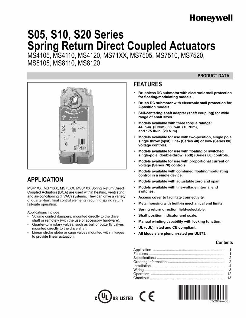
APPLICATIONMS41XX, MS71XX, MS75XX, MS81XX Spring Return Direct Coupled Actuators (DCA) are used within heating, ventilating, and air-conditioning (HVAC) systems. They can drive a variety of quarter-turn, final control elements requiring spring return fail-safe operation.
Applications include:• Volume control dampers, mounted directly to the drive
shaft or remotely (with the use of accessory hardware).• Quarter-turn rotary valves, such as ball or butterfly valves
mounted directly to the drive shaft.• Linear stroke globe or cage valves mounted with linkages
to provide linear actuation.
FEATURES• Brushless DC submotor with electronic stall protection
for floating/modulating models.• Brush DC submotor with electronic stall protection for
2-position models.• Self-centering shaft adapter (shaft coupling) for wide
range of shaft sizes.• Models available with three torque ratings:
44 lb-in. (5 N•m), 88 lb-in. (10 N•m), and 175 lb-in. (20 N•m).
• Models available for use with two-position, single pole single throw (spst), line- (Series 40) or low- (Series 80) voltage controls.
• Models available for use with floating or switched single-pole, double-throw (spdt) (Series 60) controls.
• Models available for use with proportional current or voltage (Series 70) controls.
• Models available with combined floating/modulating control in a single device.
• Models available with adjustable zero and span.• Models available with line-voltage internal end
switches.• Access cover to facilitate connectivity.• Metal housing with built-in mechanical end limits.• Spring return direction field-selectable.• Shaft position indicator and scale.• Manual winding capability with locking function.• UL (cUL) listed and CE compliant.• All Models are plenum-rated per UL873.
ContentsApplication ....................................................................... 1Features ........................................................................... 1Specifications ................................................................... 2Ordering Information ........................................................ 2Installation ........................................................................ 4Wiring ............................................................................... 8Operation ......................................................................... 12Checkout .......................................................................... 13
S05, S10, S20 SERIES SPRING RETURN DIRECT COUPLED ACTUATORS
63-2607—06 2
ORDERING INFORMATIONWhen purchasing replacement and modernization products from your TRADELINE® wholesaler or distributor, refer to the TRADELINE® Catalog or price sheets for complete ordering number.
If you have additional questions, need further information, or would like to comment on our products or services, please write or phone:
1. Your local Honeywell Automation and Control Products Sales Office (check white pages of your phone directory).2. Honeywell Customer Care
1885 Douglas Drive NorthMinneapolis, Minnesota 55422-4386
In Canada—Honeywell Limited/Honeywell Limitée, 35 Dynamic Drive, Toronto, Ontario M1V 4Z9.International Sales and Service Offices in all principal cities of the world. Manufacturing in Australia, Canada, Finland, France, Germany, Japan, Mexico, Netherlands, Spain, Taiwan, United Kingdom, U.S.A.
SPECIFICATIONSModels: See Tables 2 and 3.
NOTE: This document also covers the MS7110K and MS7106K.
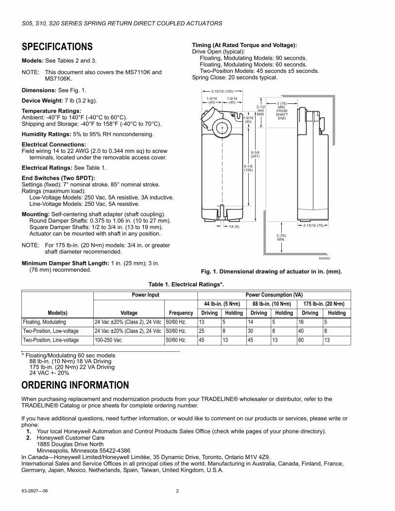
Dimensions: See Fig. 1.
Device Weight: 7 lb (3.2 kg).
Temperature Ratings:Ambient: -40°F to 140°F (-40°C to 60°C).Shipping and Storage: -40°F to 158°F (-40°C to 70°C).
Humidity Ratings: 5% to 95% RH noncondensing.
Electrical Connections:Field wiring 14 to 22 AWG (2.0 to 0.344 mm sq) to screw
terminals, located under the removable access cover.
Electrical Ratings: See Table 1.
End Switches (Two SPDT):Settings (fixed): 7° nominal stroke, 85° nominal stroke.Ratings (maximum load):
Low-Voltage Models: 250 Vac, 5A resistive, 3A inductive.Line-Voltage Models: 250 Vac, 5A resistive.
Mounting: Self-centering shaft adapter (shaft coupling).Round Damper Shafts: 0.375 to 1.06 in. (10 to 27 mm).Square Damper Shafts: 1/2 to 3/4 in. (13 to 19 mm).Actuator can be mounted with shaft in any position.
NOTE: For 175 lb-in. (20 N•m) models: 3/4 in. or greater shaft diameter recommended.
Minimum Damper Shaft Length: 1 in. (25 mm); 3 in. (76 mm) recommended.
Timing (At Rated Torque and Voltage):Drive Open (typical):
Floating, Modulating Models: 90 seconds.Floating, Modulating Models: 60 seconds.Two-Position Models: 45 seconds ±5 seconds.
Spring Close: 20 seconds typical.
Fig. 1. Dimensional drawing of actuator in in. (mm).
Table 1. Electrical Ratings*.
* Floating/Modulating 60 sec models88 lb-in. (10 N•m) 18 VA Driving175 lb-in. (20 N•m) 22 VA Driving 24 VAC +- 20%
9-3/4(247)
1-9/16(40)
2-1/2(64)MIN.
3 (76)MIN.
3 (76)MIN.
FROMSHAFT
END
6-1/8(156)
1-9/16(40)
1-9/16(40)
3-15/16 (100)
2-15/16 (75)1/4 (6)
M20952
Model(s)
Power Input Power Consumption (VA)
Voltage Frequency44 lb-in. (5 N•m) 88 lb-in. (10 N•m) 175 lb-in. (20 N•m)
Driving Holding Driving Holding Driving HoldingFloating, Modulating 24 Vac ±20% (Class 2), 24 Vdc 50/60 Hz. 13 5 14 5 16 5Two-Position, Low-voltage 24 Vac ±20% (Class 2), 24 Vdc 50/60 Hz. 25 8 30 8 40 8Two-Position, Line-voltage 100-250 Vac 50/60 Hz. 45 13 45 13 60 13
S05, S10, S20 SERIES SPRING RETURN DIRECT COUPLED ACTUATORS
3 63-2607—06
60 second modelsMS7510A2016MS7510A2214MS7520A2015MS7520A2213
Stroke: 95° ±3°, mechanically limited.
Approvals: See Table 4.
Design Life (at Rated Voltage):**Two-position models: 50,000 full stroke cycles;
50,000 full stroke spring returns.Floating and Modulating models: 60,000 full stroke cycles;
1,500,000 repositions; 60,000 full stroke spring returns.
Controller Type:S05, S10, S20: See Table 3.S05, S10, S20: Modulating (Series 70) or Floating (Series 60);
controlled by selector switch.MS71XX: Modulating Voltage Input.Input Impedance: 95K ohms minimum.Feedback Signal: 0 or 2-10 Vdc;
Driving current is 3 mA minimum.
Torque Ratings:Typical Holding, Driving, Spring Return:
S05: 44 lb-in. (5 N•m).S10: 88 lb-in. (10 N•m).S20: 175 lb-in. (20 N•m).
Stall Maximum (fully open at 75°F): S05: 100 lb-in. (11.3 N•m).S10: 200 lb-in. (22.6 N•m).S20: 350 lb-in. (39.6 N•m).
Noise Rating at 1m (Maximum):Holding: 20 dBA (no audible noise).Two-position models:
Driving: 50 dBA.Spring Return: 65 dBA.
Floating and Modulating models:Driving: 40 dBA.Spring Return: 50 dBA.
Table 4. Approvals.
Environmental Protection Ratings:NEMA2 (US Models) or IP54 (European Models) when
mounted on a horizontal shaft with access cover below the shaft.
Accessories:27518 Balljoint (5/16 in.).103598 Balljoint (1/4 in.).205860 Electronic Minimum Position Potentiometer.27520A-E,G,H-L,Q Pushrod (5/16 in. diameter).32000085-001 Water-tight Cable Gland/Strain-relief Fitting (10
pack).32003036-001 Weather Enclosure.32004254-002 Self-Centering Shaft Adapter (supplied with
actuator).50001194-001 Foot Mount Kit.50005859-001 NEMA4/4X Enclosure.50006427-001 Anti-Rotation Bracket (supplied with actuator).SW2-US Auxiliary Switch Package.See also Form 62-2620.
** Floating/Modulating 60 sec models20,000 full stroke cycles100,000 repositions
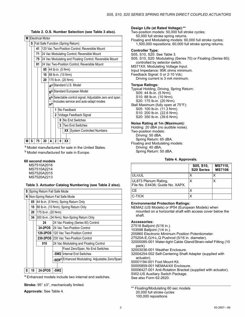
Table 2. O.S. Number Selection (see Table 3 also).
a Model manufactured for sale in the United States.b Model manufactured for sale in Europe.
M Electrical MotorS Fail Safe Function (Spring Return)
41 120 Vac Two-Position Control; Reversible Mount71 24 Vac Modulating Control; Reversible Mount75 24 Vac Modulating and Floating Control; Reversible Mount81 24 Vac Two-Position Control; Reversible Mount
05 44 lb-in. (5 N•m)10 88 lb-in. (10 N•m)20 175 lb-in. (20 N•m)
Aa Standard U.S. Model
Bb Standard European Model
Eb Selectable control signal; Adjustable zero and span; Includes service and auto-adapt modes
Ha
1 No Feedback2 Voltage Feedback Signal
0 No End Switches2 Two End Switches
XX System Controlled Numbers
M S 75 20 A 2 0 XX
Table 3. Actuator Catalog Numbering (see Table 2 also).
a Enhanced models include two internal end switches.
S Spring Return Fail Safe ModeN Non-Spring Return Fail Safe Mode
05 44 lb-in. (5 N•m); Spring Return Only10 88 lb-in. (10 N•m); Spring Return Only20 175 lb-in. (20 N•m)34 300 lb-in. (34 N•m); Non-Spring Return Only
24 24 Vac Floating (Series 60) Control24-2POS 24 Vac Two-Position Control
120-2POS 120 Vac Two-Position Control230-2POS 230 Vac Two-Position Control
010 24 Vac Modulating and Floating ControlFixed Zero/Span, No End Switches
-SW2 Internal End Switches-SERa Enhanced Modulating; Adjustable Zero/Span
S 10 24-2POS -SW2
S05, S10, S20 Series
MS7110,MS7106
UL/cUL X XUL873 Plenum Rating, File No. E4436; Guide No. XAPX.
X X
CE XC-TICK X
S05, S10, S20 SERIES SPRING RETURN DIRECT COUPLED ACTUATORS
63-2607—06 4
SizingRequired TorqueIn lieu of data from a Specification Engineer or Manufacturer, required torque for a given damper load can be determined using the following method:
Where:— TR = Required torque for the damper load.— TD = Damper torque rating from the manufacturer,
expressed in either (lb-in.)/(sq ft) or (N•m)/(sq m). the damper load.
— AD = Damper area expressed in either sq ft or sq m.
Actuators RequiredIn lieu of data from a Specification Engineer or Manufacturer, the number of required actuators for a given damper load can be determined using the following method:
Where:— N = Number of actuators.— TR = Required torque for the damper load. (See above.)— TA = Actuator torque rating.— SF = Safety factor.
NOTE: The safety factor accounts for variables such as mis-alignments, aging of the damper, etc. 0.8 is a typical safety factor.
INSTALLATION
When Installing this Product...1. Read these instructions carefully. Failure to follow
them could damage the product or cause a hazardous condition.
2. Check the ratings given in the instructions and on the product to make sure the product is suitable for your application.
3. Installer must be a trained, experienced service technician.
4. After installation is complete, check out product operation as provided in these instructions.
CAUTIONElectrical Shock or Equipment Damage Hazard.Low voltage can shock individuals or short equipment circuitry.Disconnect power supply before installation.
IMPORTANTAll wiring must agree with applicable codes, ordinances and regulations.
LocationThese actuators are designed to mount directly to a damper external drive shaft. The shaft coupling fastens to the drive shaft. The actuator housing includes slots which, along with an anti-rotation bracket, secure the actuator to the damper frame or duct work (see Fig. 8).
NOTES:— When mounted correctly, these slots allow the
actuator to float without rotating relative to the damper shaft.
— Using other brackets or linkages, the actuator can be foot-mounted or tandem-mounted.
CAUTIONMotor Damage Hazard.Deteriorating vapors and acid fumes can damage metal parts.Install motor in areas free of acid fumes and other deteriorating vapors.
CAUTIONEquipment Damage Hazard.Tightly securing actuator to damper housing can damage actuator.Mount actuator to allow it to float along its vertical axis.
PreparationBefore mounting the actuator onto the damper shaft, determine the:— Damper/valve opening direction for correct spring return
rotation. The actuator can be mounted to provide clockwise or counterclockwise spring return.
— Damper shaft size (see the Specifications section).
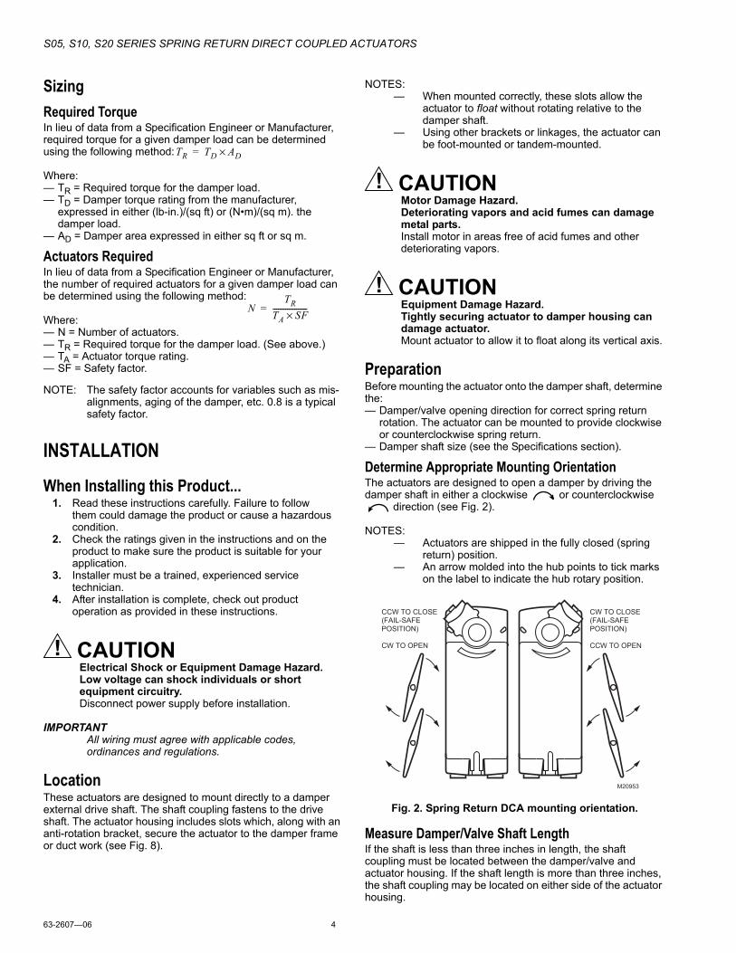
Determine Appropriate Mounting OrientationThe actuators are designed to open a damper by driving the damper shaft in either a clockwise or counterclockwise
direction (see Fig. 2).
NOTES:— Actuators are shipped in the fully closed (spring
return) position.— An arrow molded into the hub points to tick marks
on the label to indicate the hub rotary position.
Fig. 2. Spring Return DCA mounting orientation.
Measure Damper/Valve Shaft LengthIf the shaft is less than three inches in length, the shaft coupling must be located between the damper/valve and actuator housing. If the shaft length is more than three inches, the shaft coupling may be located on either side of the actuator housing.
TR TD AD×=
NTR
TA SF×-------------------=
M20953
CCW TO CLOSE
(FAIL-SAFE
POSITION)
CW TO OPEN
CW TO CLOSE
(FAIL-SAFE
POSITION)
CCW TO OPEN
S05, S10, S20 SERIES SPRING RETURN DIRECT COUPLED ACTUATORS
5 63-2607—06
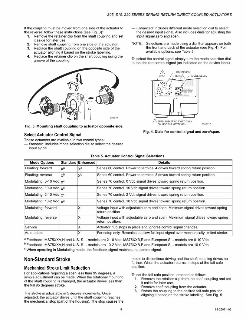
If the coupling must be moved from one side of the actuator to the reverse, follow these instructions (see Fig. 3):
1. Remove the retainer clip from the shaft coupling and set it aside for later use.
2. Remove shaft coupling from one side of the actuator.3. Replace the shaft coupling on the opposite side of the
actuator aligning it based on the stroke labelling.4. Replace the retainer clip on the shaft coupling using the
groove of the coupling.
Fig. 3. Mounting shaft coupling to actuator opposite side.
Select Actuator Control SignalThese actuators are available in two control types:— Standard: includes mode selection dial to select the desired
input signal.
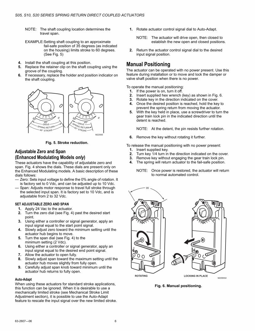
— Enhanced: includes different mode selection dial to select the desired input signal. Also includes dials for adjusting the input signal zero and span.
NOTE: Selections are made using a dial that appears on both the front and back of the actuator (see Fig. 4). For available options, see Table 5.
To select the control signal simply turn the mode selection dial to the desired control signal (as indicated on the device label).
Fig. 4. Dials for control signal and zero/span.
Table 5. Actuator Control Signal Selections.
a Feedback: MS75XXA,H and U.S. S… models are 2-10 Vdc, MS75XXB,E and European S… models are 0-10 Vdc.b Feedback: MS75XXA,H and U.S. S… models are 10-2 Vdc, MS75XXB,E and European S… models are 10-0 Vdc.c When operating in Modulating mode, the feedback signal matches the control signal.
Non-Standard StrokeMechanical Stroke Limit ReductionFor applications requiring a span less than 95 degrees, a simple adjustment can be made. When the rotational mounting of the shaft coupling is changed, the actuator drives less than the full 95 degrees stroke.
The stroke is adjustable in 5 degree increments. Once adjusted, the actuator drives until the shaft coupling reaches the mechanical stop (part of the housing). The stop causes the
motor to discontinue driving and the shaft coupling drives no farther. When the actuator returns, it stops at the fail-safe position.
To set the fail-safe position, proceed as follows:1. Remove the retainer clip from the shaft coupling and set
it aside for later use.2. Remove shaft coupling from the actuator.3. Rotate the coupling to the desired fail-safe position,
aligning it based on the stroke labelling. See Fig. 5.
M19579
32007163-011 Rev. C
Modulating, ForwardModulating, ReverseFloating, ForwardFloating, ReverseServiceAuto Adapt
Start
0V
10V
2V
32V
Span
M20954A
ZERO
LOCKING PIN
SPAN MODE SELECT
1
1
1
SPAN AND ZERO EXIST ONLY
ON MODELS MS75XXE,H.
Mode Options Standard Enhanced DetailsFloating: forward Xa Xa Series 60 control. Power to terminal 4 drives toward spring return position.
Floating: reverse Xb Xb Series 60 control. Power to terminal 3 drives toward spring return position.
Modulating: 0-10 Vdc Xc Series 70 control. 0 Vdc signal drives toward spring return position.
Modulating: 10-0 Vdc Xc Series 70 control. 10 Vdc signal drives toward spring return position.
Modulating: 2-10 Vdc Xc Series 70 control. 2 Vdc signal drives toward spring return position.
Modulating: 10-2 Vdc Xc Series 70 control. 10 Vdc signal drives toward spring return position.
Modulating: forward X Voltage input with adjustable zero and span. Minimum signal drives toward spring return position.
Modulating: reverse X Voltage input with adjustable zero and span. Maximum signal drives toward spring return position.
Service X Actuator hub stops in place and ignores control signal changes.Auto-adapt X For setup only. Rescales to allow full input signal over mechanically limited stroke.
S05, S10, S20 SERIES SPRING RETURN DIRECT COUPLED ACTUATORS
63-2607—06 6
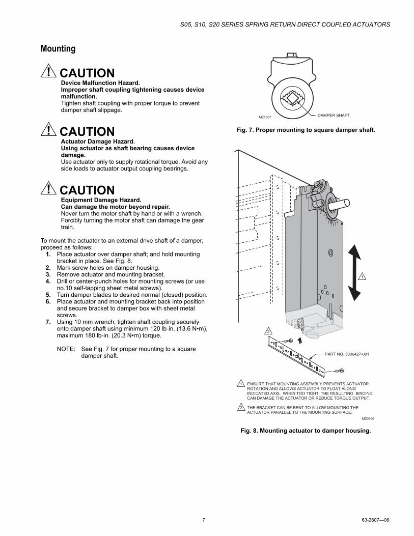
NOTE: The shaft coupling location determines the travel span.
EXAMPLE:Setting shaft coupling to an approximate fail-safe position of 35 degrees (as indicated on the housing) limits stroke to 60 degrees. (See Fig. 5)
4. Install the shaft coupling at this position.5. Replace the retainer clip on the shaft coupling using the
groove of the coupling.6. If necessary, replace the holder and position indicator on
the shaft coupling.
Fig. 5. Stroke reduction.
Adjustable Zero and Span (Enhanced Modulating Models only)These actuators have the capability of adjustable zero and span. Fig. 4 shows the dials. These dials are present only on the Enhanced Modulating models. A basic description of these dials follows:— Zero: Sets input voltage to define the 0% angle of rotation. It
is factory set to 0 Vdc, and can be adjusted up to 10 Vdc.— Span: Adjusts motor response to travel full stroke through
the selected input span. It is factory set to 10 Vdc, and is adjustable from 2 to 32 Vdc.
SET ADJUSTABLE ZERO AND SPAN1. Apply 24 Vac to the actuator.2. Turn the zero dial (see Fig. 4) past the desired start
point.3. Using either a controller or signal generator, apply an
input signal equal to the start point signal.4. Slowly adjust zero toward the minimum setting until the
actuator hub begins to move.5. Turn the span dial (see Fig. 4) to the
minimum setting (2 Vdc).6. Using either a controller or signal generator, apply an
input signal equal to the desired end point signal.7. Allow the actuator to open fully.8. Slowly adjust span toward the maximum setting until the
actuator hub moves slightly from fully open.9. Carefully adjust span knob toward minimum until the
actuator hub returns to fully open.
Auto-AdaptWhen using these actuators for standard stroke applications, this function can be ignored. When it is desirable to use a mechanically limited stroke (see Mechanical Stroke Limit Adjustment section), it is possible to use the Auto-Adapt feature to rescale the input signal over the new limited stroke.
1. Rotate actuator control signal dial to Auto-Adapt.
NOTE: The actuator will drive open, then closed to establish the new open and closed positions.
2. Return the actuator control signal dial to the desired input signal position.
Manual PositioningThe actuator can be operated with no power present. Use this feature during installation or to move and lock the damper or valve shaft position when there is no power.
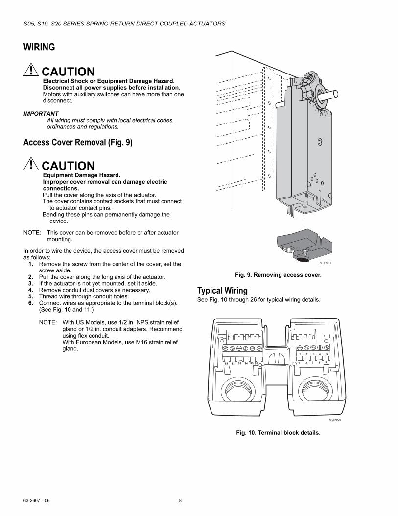
To operate the manual positioning:1. If the power is on, turn it off.2. Insert supplied hex wrench (key) as shown in Fig. 6.3. Rotate key in the direction indicated on the cover.4. Once the desired position is reached, hold the key to
prevent the spring return from moving the actuator.5. With the key held in place, use a screwdriver to turn the
gear train lock pin in the indicated direction until the detent is reached.
NOTE: At the detent, the pin resists further rotation.
6. Remove the key without rotating it further.
To release the manual positioning with no power present:1. Insert supplied key.2. Turn key 1/4 turn in the direction indicated on the cover.3. Remove key without engaging the gear train lock pin.4. The spring will return actuator to the fail-safe position.
NOTE: Once power is restored, the actuator will return to normal automated control.
Fig. 6. Manual positioning.
DRIVESPRING RETURN
90 STROKE
45
M22065
90 0
DRIVESPRING RETURN60STROKE
45
90 0
M20955AROTATING LOCKING IN PLACE
95
S05, S10, S20 SERIES SPRING RETURN DIRECT COUPLED ACTUATORS
7 63-2607—06
Mounting
CAUTIONDevice Malfunction Hazard.Improper shaft coupling tightening causes device malfunction.Tighten shaft coupling with proper torque to prevent damper shaft slippage.
CAUTIONActuator Damage Hazard.Using actuator as shaft bearing causes device damage.Use actuator only to supply rotational torque. Avoid any side loads to actuator output coupling bearings.
CAUTIONEquipment Damage Hazard.Can damage the motor beyond repair.Never turn the motor shaft by hand or with a wrench.Forcibly turning the motor shaft can damage the gear train.
To mount the actuator to an external drive shaft of a damper, proceed as follows:
1. Place actuator over damper shaft; and hold mounting bracket in place. See Fig. 8.
2. Mark screw holes on damper housing.3. Remove actuator and mounting bracket.4. Drill or center-punch holes for mounting screws (or use
no.10 self-tapping sheet metal screws).5. Turn damper blades to desired normal (closed) position.6. Place actuator and mounting bracket back into position
and secure bracket to damper box with sheet metal screws.
7. Using 10 mm wrench, tighten shaft coupling securely onto damper shaft using minimum 120 lb-in. (13.6 N•m), maximum 180 lb-in. (20.3 N•m) torque.
NOTE: See Fig. 7 for proper mounting to a square damper shaft.
Fig. 7. Proper mounting to square damper shaft.
Fig. 8. Mounting actuator to damper housing.
DAMPER SHAFTM21007
M20956
ENSURE THAT MOUNTING ASSEMBLY PREVENTS ACTUATOR
ROTATION AND ALLOWS ACTUATOR TO FLOAT ALONG
INDICATED AXIS. WHEN TOO TIGHT, THE RESULTING BINDING
CAN DAMAGE THE ACTUATOR OR REDUCE TORQUE OUTPUT.
THE BRACKET CAN BE BENT TO ALLOW MOUNTING THE
ACTUATOR PARALLEL TO THE MOUNTING SURFACE.
1
PART NO. 5006427-001
1
2
2
S05, S10, S20 SERIES SPRING RETURN DIRECT COUPLED ACTUATORS
63-2607—06 8
WIRING
CAUTIONElectrical Shock or Equipment Damage Hazard.Disconnect all power supplies before installation.Motors with auxiliary switches can have more than one disconnect.
IMPORTANTAll wiring must comply with local electrical codes, ordinances and regulations.
Access Cover Removal (Fig. 9)
CAUTIONEquipment Damage Hazard.Improper cover removal can damage electric connections.Pull the cover along the axis of the actuator.The cover contains contact sockets that must connect
to actuator contact pins.Bending these pins can permanently damage the
device.
NOTE: This cover can be removed before or after actuator mounting.
In order to wire the device, the access cover must be removed as follows:
1. Remove the screw from the center of the cover, set the screw aside.
2. Pull the cover along the long axis of the actuator.3. If the actuator is not yet mounted, set it aside.4. Remove conduit dust covers as necessary.5. Thread wire through conduit holes.6. Connect wires as appropriate to the terminal block(s).
(See Fig. 10 and 11.)
NOTE: With US Models, use 1/2 in. NPS strain relief gland or 1/2 in. conduit adapters. Recommend using flex conduit.With European Models, use M16 strain relief gland.
Fig. 9. Removing access cover.
Typical WiringSee Fig. 10 through 26 for typical wiring details.
Fig. 10. Terminal block details.
M20957
1 2 3 4 5
1 2 3 4 5
S1 S2 S3 S4 S5 S6
M20958
S05, S10, S20 SERIES SPRING RETURN DIRECT COUPLED ACTUATORS
9 63-2607—06
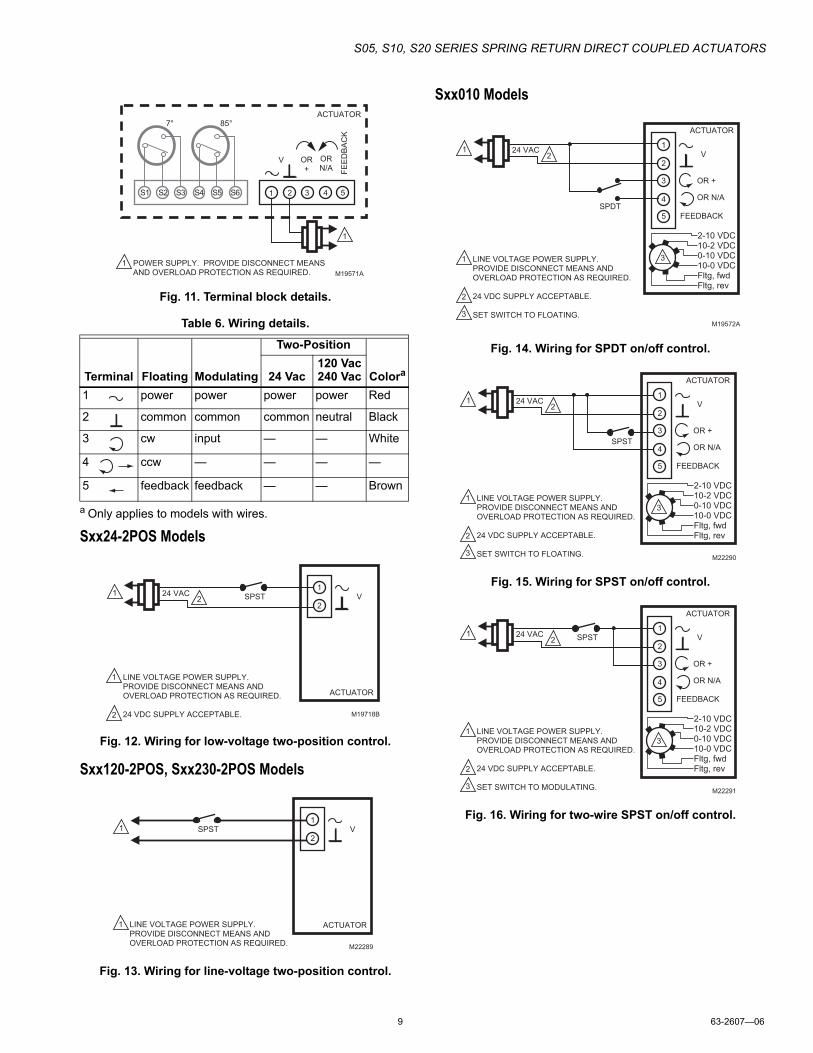
Fig. 11. Terminal block details.
Table 6. Wiring details.
a Only applies to models with wires.
Sxx24-2POS Models
Fig. 12. Wiring for low-voltage two-position control.
Sxx120-2POS, Sxx230-2POS Models
Fig. 13. Wiring for line-voltage two-position control.
Sxx010 Models
Fig. 14. Wiring for SPDT on/off control.
Fig. 15. Wiring for SPST on/off control.
Fig. 16. Wiring for two-wire SPST on/off control.
Terminal Floating Modulating
Two-Position
Colora24 Vac120 Vac 240 Vac
1 power power power power Red
2 common common common neutral Black
3 cw input — — White
4 ccw — — — —
5 feedback feedback — — Brown
1 POWER SUPPLY. PROVIDE DISCONNECT MEANS
AND OVERLOAD PROTECTION AS REQUIRED.
V OR
+
OR
N/A
FE
ED
BA
CK
ACTUATOR
1
5431
7° 85°
S1 S2 S3 S4 S5 S6 2
M19571A
ACTUATOR
SPST24 VAC1
1
2
2
LINE VOLTAGE POWER SUPPLY.
PROVIDE DISCONNECT MEANS AND
OVERLOAD PROTECTION AS REQUIRED.
24 VDC SUPPLY ACCEPTABLE.
V1
2
M19718B
ACTUATOR
SPST1
1 LINE VOLTAGE POWER SUPPLY.
PROVIDE DISCONNECT MEANS AND
OVERLOAD PROTECTION AS REQUIRED.
V1
2
M22289
SPDT
24 VAC1
1
2
3
2
LINE VOLTAGE POWER SUPPLY.
PROVIDE DISCONNECT MEANS AND
OVERLOAD PROTECTION AS REQUIRED.
24 VDC SUPPLY ACCEPTABLE.
SET SWITCH TO FLOATING.M19572A
ACTUATOR
V
OR +
OR N/A
FEEDBACK5
4
3
1
2
2-10 VDC10-2 VDC0-10 VDC10-0 VDCFltg, fwdFltg, rev
3
ACTUATOR
SPST
24 VAC1
1
2
3
2
LINE VOLTAGE POWER SUPPLY.
PROVIDE DISCONNECT MEANS AND
OVERLOAD PROTECTION AS REQUIRED.
24 VDC SUPPLY ACCEPTABLE.
SET SWITCH TO FLOATING.
V
OR +
OR N/A
FEEDBACK5
4
3
1
2
M22290
2-10 VDC10-2 VDC0-10 VDC10-0 VDCFltg, fwdFltg, rev
3
ACTUATOR
SPST24 VAC1
1
2
3
2
LINE VOLTAGE POWER SUPPLY.
PROVIDE DISCONNECT MEANS AND
OVERLOAD PROTECTION AS REQUIRED.
24 VDC SUPPLY ACCEPTABLE.
SET SWITCH TO MODULATING.
V
OR +
OR N/A
FEEDBACK5
4
3
1
2
M22291
2-10 VDC10-2 VDC0-10 VDC10-0 VDCFltg, fwdFltg, rev
3
S05, S10, S20 SERIES SPRING RETURN DIRECT COUPLED ACTUATORS
63-2607—06 10
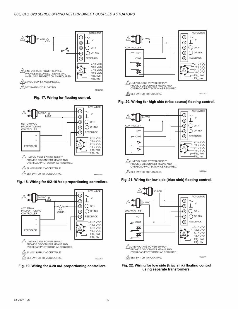
Fig. 17. Wiring for floating control.
Fig. 18. Wiring for 0/2-10 Vdc proportioning controllers.
Fig. 19. Wiring for 4-20 mA proportioning controllers.
Fig. 20. Wiring for high side (triac source) floating control.
Fig. 21. Wiring for low side (triac sink) floating control.
Fig. 22. Wiring for low side (triac sink) floating control using separate transformers.
24 VAC1
1
2
3
2
LINE VOLTAGE POWER SUPPLY.
PROVIDE DISCONNECT MEANS AND
OVERLOAD PROTECTION AS REQUIRED.
24 VDC SUPPLY ACCEPTABLE.
SET SWITCH TO FLOATING.M19573A
ACTUATOR
V
OR +
OR N/A
FEEDBACK5
4
3
1
2
2-10 VDC10-2 VDC0-10 VDC10-0 VDCFltg, fwdFltg, rev
3
ACTUATOR
0/2 TO 10 VDC
PROPORTIONING
CONTROLLER
24 VAC1
1
2
3
2
LINE VOLTAGE POWER SUPPLY.
PROVIDE DISCONNECT MEANS AND
OVERLOAD PROTECTION AS REQUIRED.
24 VDC SUPPLY ACCEPTABLE.
SET SWITCH TO MODULATING.
V
OR +
OR N/A
FEEDBACK
–
+
FEEDBACK
5
4
3
1
2
M19574A
2-10 VDC10-2 VDC0-10 VDC10-0 VDCFltg, fwdFltg, rev
3
ACTUATOR
4 TO 20 mA
PROPORTIONING
CONTROLLER
24 VAC1
1
2
3
2
500
OHMS
LINE VOLTAGE POWER SUPPLY.
PROVIDE DISCONNECT MEANS AND
OVERLOAD PROTECTION AS REQUIRED.
24 VDC SUPPLY ACCEPTABLE.
SET SWITCH TO MODULATING.
V
OR +
OR N/A
FEEDBACK
–
+
FEEDBACK
5
4
3
1
2
M22282
2-10 VDC10-2 VDC0-10 VDC10-0 VDCFltg, fwdFltg, rev
3
ACTUATOR
CONTROLLER
24 VAC1
1
2
LINE VOLTAGE POWER SUPPLY.
PROVIDE DISCONNECT MEANS AND
OVERLOAD PROTECTION AS REQUIRED.
SET SWITCH TO FLOATING.
V
OR +
OR N/A
FEEDBACK
HOT
COM 5
4
3
1
2
M22283
2-10 VDC10-2 VDC0-10 VDC10-0 VDCFltg, fwdFltg, rev
2
ACTUATOR
CONTROLLER
24 VAC1
1
2
LINE VOLTAGE POWER SUPPLY.
PROVIDE DISCONNECT MEANS AND
OVERLOAD PROTECTION AS REQUIRED.
SET SWITCH TO FLOATING.
V
OR +
OR N/A
FEEDBACK
HOT
COM 5
4
3
1
2
M22284
2-10 VDC10-2 VDC0-10 VDC10-0 VDCFltg, fwdFltg, rev
2
ACTUATOR
CONTROLLER
24 VAC1
1
2
LINE VOLTAGE POWER SUPPLY.
PROVIDE DISCONNECT MEANS AND
OVERLOAD PROTECTION AS REQUIRED.
SET SWITCH TO FLOATING.
V
OR +
OR N/A
FEEDBACK
HOT
COM 5
4
3
1
2
M22285
24 VAC1
2-10 VDC10-2 VDC0-10 VDC10-0 VDCFltg, fwdFltg, rev
2
S05, S10, S20 SERIES SPRING RETURN DIRECT COUPLED ACTUATORS
11 63-2607—06
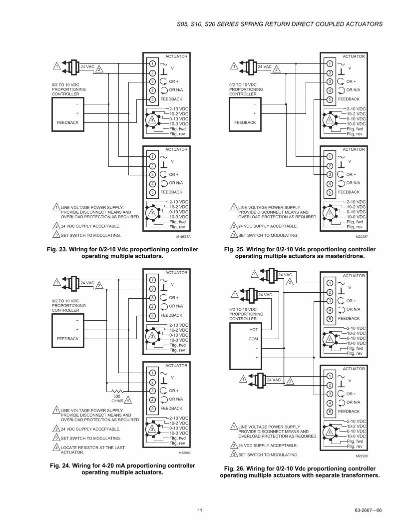
Fig. 23. Wiring for 0/2-10 Vdc proportioning controller operating multiple actuators.
Fig. 24. Wiring for 4-20 mA proportioning controller operating multiple actuators.
Fig. 25. Wiring for 0/2-10 Vdc proportioning controller operating multiple actuators as master/drone.
Fig. 26. Wiring for 0/2-10 Vdc proportioning controller operating multiple actuators with separate transformers.
ACTUATOR
0/2 TO 10 VDC
PROPORTIONING
CONTROLLER
24 VAC1
1
2
3
2
LINE VOLTAGE POWER SUPPLY.
PROVIDE DISCONNECT MEANS AND
OVERLOAD PROTECTION AS REQUIRED.
24 VDC SUPPLY ACCEPTABLE.
SET SWITCH TO MODULATING.
V
OR +
OR N/A
FEEDBACK
–
+
FEEDBACK
5
4
3
1
2
M19575A
2-10 VDC10-2 VDC0-10 VDC10-0 VDCFltg, fwdFltg, rev
3
ACTUATOR
V
OR +
OR N/A
FEEDBACK5
4
3
1
2
2-10 VDC10-2 VDC0-10 VDC10-0 VDCFltg, fwdFltg, rev
3
ACTUATOR
0/2 TO 10 VDC
PROPORTIONING
CONTROLLER
24 VAC1
1
2
3
4
4
2
LINE VOLTAGE POWER SUPPLY.
PROVIDE DISCONNECT MEANS AND
OVERLOAD PROTECTION AS REQUIRED.
24 VDC SUPPLY ACCEPTABLE.
SET SWITCH TO MODULATING.
LOCATE RESISTOR AT THE LAST
ACTUATOR.
V
OR +
OR N/A
FEEDBACK
–
+
FEEDBACK
5
4
3
1
2
M22286
2-10 VDC10-2 VDC0-10 VDC10-0 VDCFltg, fwdFltg, rev
3
ACTUATOR
V
OR +
OR N/A
FEEDBACK5
4
3
1
2
2-10 VDC10-2 VDC0-10 VDC10-0 VDCFltg, fwdFltg, rev
3
500
OHMS
ACTUATOR
0/2 TO 10 VDC
PROPORTIONING
CONTROLLER
24 VAC1
1
2
3
2
LINE VOLTAGE POWER SUPPLY.
PROVIDE DISCONNECT MEANS AND
OVERLOAD PROTECTION AS REQUIRED.
24 VDC SUPPLY ACCEPTABLE.
SET SWITCH TO MODULATING.
V
OR +
OR N/A
FEEDBACK
–
+
FEEDBACK
5
4
3
1
2
M22287
2-10 VDC10-2 VDC0-10 VDC10-0 VDCFltg, fwdFltg, rev
3
ACTUATOR
V
OR +
OR N/A
FEEDBACK5
4
3
1
2
2-10 VDC10-2 VDC0-10 VDC10-0 VDCFltg, fwdFltg, rev
3
ACTUATOR
0/2 TO 10 VDC
PROPORTIONING
CONTROLLER
1
2
3
2
LINE VOLTAGE POWER SUPPLY.
PROVIDE DISCONNECT MEANS AND
OVERLOAD PROTECTION AS REQUIRED.
24 VDC SUPPLY ACCEPTABLE.
SET SWITCH TO MODULATING.
V
OR +
OR N/A
FEEDBACK5
4
3
1
2
M22288
2-10 VDC10-2 VDC0-10 VDC10-0 VDCFltg, fwdFltg, rev
3
ACTUATOR
V
OR +
OR N/A
FEEDBACK5
4
3
1
2
2-10 VDC10-2 VDC0-10 VDC10-0 VDCFltg, fwdFltg, rev
3
24 VAC1
24 VAC1
224 VAC1
HOT
COM
–
+
S05, S10, S20 SERIES SPRING RETURN DIRECT COUPLED ACTUATORS
63-2607—06 12
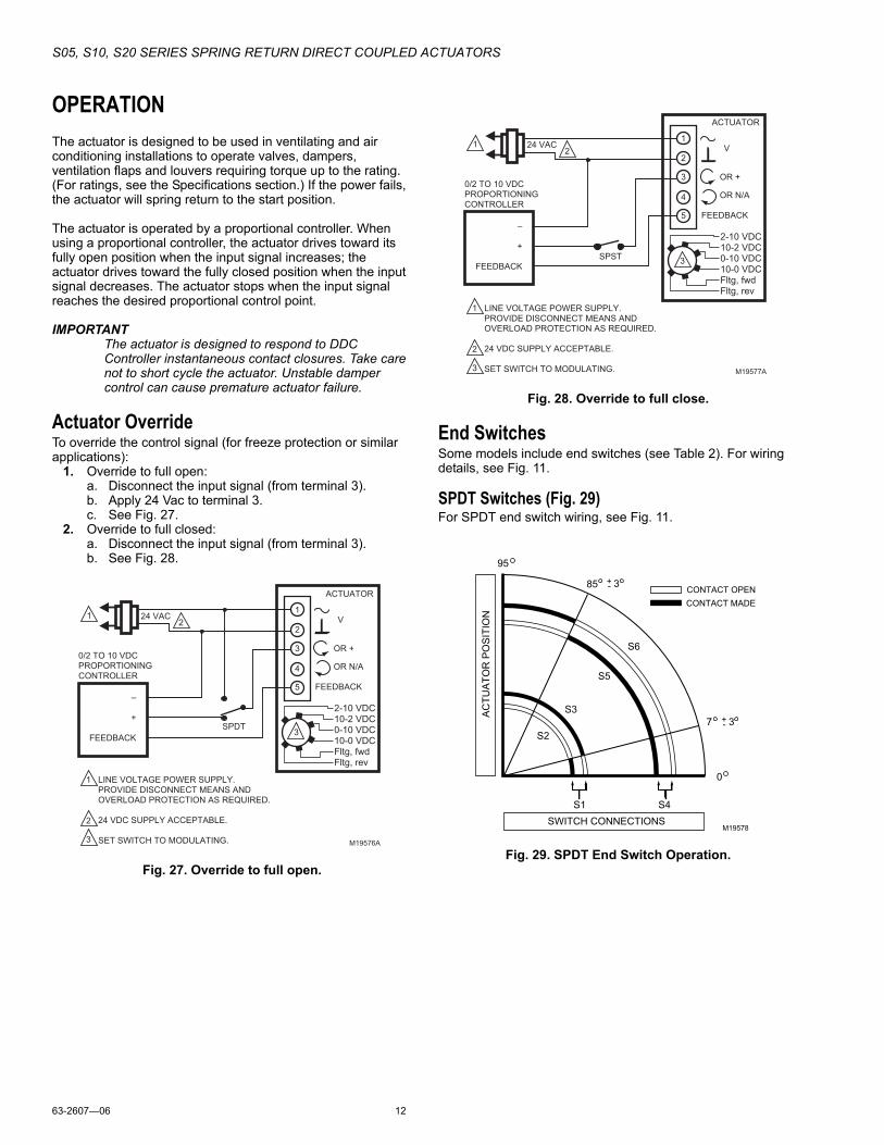
OPERATIONThe actuator is designed to be used in ventilating and air conditioning installations to operate valves, dampers, ventilation flaps and louvers requiring torque up to the rating. (For ratings, see the Specifications section.) If the power fails, the actuator will spring return to the start position.
The actuator is operated by a proportional controller. When using a proportional controller, the actuator drives toward its fully open position when the input signal increases; the actuator drives toward the fully closed position when the input signal decreases. The actuator stops when the input signal reaches the desired proportional control point.
IMPORTANTThe actuator is designed to respond to DDC Controller instantaneous contact closures. Take care not to short cycle the actuator. Unstable damper control can cause premature actuator failure.
Actuator OverrideTo override the control signal (for freeze protection or similar applications):
1. Override to full open:a. Disconnect the input signal (from terminal 3).b. Apply 24 Vac to terminal 3.c. See Fig. 27.
2. Override to full closed:a. Disconnect the input signal (from terminal 3).b. See Fig. 28.
Fig. 27. Override to full open.
Fig. 28. Override to full close.
End SwitchesSome models include end switches (see Table 2). For wiring details, see Fig. 11.
SPDT Switches (Fig. 29)For SPDT end switch wiring, see Fig. 11.
Fig. 29. SPDT End Switch Operation.
ACTUATOR
0/2 TO 10 VDC
PROPORTIONING
CONTROLLER
24 VAC1
1
2
3
2
LINE VOLTAGE POWER SUPPLY.
PROVIDE DISCONNECT MEANS AND
OVERLOAD PROTECTION AS REQUIRED.
24 VDC SUPPLY ACCEPTABLE.
SET SWITCH TO MODULATING.
V
OR +
OR N/A
FEEDBACK
–
+
FEEDBACK
5
4
3
1
2
M19576A
2-10 VDC10-2 VDC0-10 VDC10-0 VDCFltg, fwdFltg, rev
3SPDT
ACTUATOR
0/2 TO 10 VDC
PROPORTIONING
CONTROLLER
24 VAC1
1
2
3
2
LINE VOLTAGE POWER SUPPLY.
PROVIDE DISCONNECT MEANS AND
OVERLOAD PROTECTION AS REQUIRED.
24 VDC SUPPLY ACCEPTABLE.
SET SWITCH TO MODULATING.
V
OR +
OR N/A
FEEDBACK
–
+
FEEDBACK
5
4
3
1
2
M19577A
2-10 VDC10-2 VDC0-10 VDC10-0 VDCFltg, fwdFltg, rev
3SPST
M19578
95
SWITCH CONNECTIONS
AC
TU
AT
OR
PO
SIT
ION
85
7 3
0
S4S1
S6
S5
S3
S2
CONTACT OPEN
CONTACT MADE
+-
3+-
S05, S10, S20 SERIES SPRING RETURN DIRECT COUPLED ACTUATORS
13 63-2607—06
CHECKOUT
Modulating/Floating Operation1. Mount actuator for required application (either clock-
wise or counterclockwise rotation to open the damper).
2. Connect power to terminals 1 and 2. (See Fig. 11 and Table 6.)
3. Set “Mode Select” dial to desired control signal.(See Fig. 4 and Table 5.)
4. Apply control signal for actuator 100% position.(See Fig. 11 and Table 6.)a. (0)2-10 Vdc: apply 10 Vdc signal to terminal 3.b. 10-(0)2 Vdc: apply (0)2 Vdc signal to terminal 3.c. (0)4-20 mA: apply 20 mA signal to terminal 3.d. 20-(0)4mA: apply (0)4 mA signal to terminal 3.e. Floating: apply 24 Vac to appropriate CW (3) or CCW
(4) terminal.5. Actuator drives to 100% position.6. Apply control signal for actuator 0% position.
(See Fig. 11 and Table 6.)a. (0)2-10 Vdc: apply (0)2 Vdc signal to terminal 3.b. 10-(0)2 Vdc: apply 10 Vdc signal to terminal 3.c. (0)4-20 mA: apply (0)4 mA signal to terminal 3.d. 20-(0)4mA: apply 20 mA signal to terminal 3.e. Floating: apply 24 Vac to appropriate CW (3) or CCW
(4) terminal.7. Actuator drives to 0% position.
Spring Return Operation1. Mount actuator for required application (either clock-
wise or counterclockwise rotation to open the damper).
2. Connect power to terminals 1 and 2. (See Fig. 11 and Table 6.)
NOTE: For two-position models skip to step 5.
3. Set “Mode Select” dial to desired control signal.(See Fig. 4 and Table 5.)
4. Apply control signal for actuator 50% position.(See Fig. 11 and Table 6.)a. Vdc Input Signal: apply 5-6 Vdc signal to terminal 3.b. mA Input Signal: apply 10-12 mA signal to terminal 3.
c. Floating: apply 24 Vac to appropriate CW (3) or CCW (4) terminal.
5. Allow the actuator to drive to 50% position.6. Disconnect wire from terminal 1.7. Actuator spring returns to 0% position.8. Re-connect wire to terminal 1, actuator drives towards
100% position.
Feedback Operation1. Connect a multi-meter, set for Vdc, to terminals 2 and 5.2. Apply the same signal as in step 4 of Modulating
Operation.3. The multi-meter reading increases to match the input
signal as actuator drives towards 100% position.4. Apply the same signal as in step 6 of Modulating
Operation.5. The multi-meter reading decreases to match the input
signal as actuator drives towards 0% position.
Direct Checkout1. Mount actuator for required application (either clock-
wise or counterclockwise rotation to open the damper).
2. Check damper position and make sure that 24 Vac is present at the appropriate connections. (See Fig. 10.)
3. Apply control signal to the appropriate connections to move the damper to the opposite position. The actuator should drive the damper.
4. If actuator does not run, verify that the actuator is properly installed for either clockwise or counter-clockwise rotation.
5. If actuator is correctly installed and still does not run, replace the actuator.
Two-Position Checkout1. Mount actuator for required application (either clock-
wise or counterclockwise rotation to open the damper).
2. Check damper position and make sure that power is present at terminals 1 and 2.
3. Actuator drives to 100% position.4. Disconnect power from terminals 1 and 2.5. Actuator spring-returns to 0% position.6. If actuator is correctly installed and does not run, replace
the actuator.

63-2607—06 14

15 63-2607—06
Automation and Control SolutionsHoneywell International Inc. Honeywell Limited-Honeywell Limitée1985 Douglas Drive North 35 Dynamic DriveGolden Valley, MN 55422 Toronto, Ontario M1V 4Z9customer.honeywell.com
S05, S10, S20 SERIES SPRING RETURN DIRECT COUPLED ACTUATORS
® U.S. Registered Trademark© 2007 Honeywell International Inc.63-2607—06 J.Z. Rev. 06-07