64-72 chevelle/ a body rear coilover conversion kit
TRANSCRIPT

1 | P a g e
February 3, 2014
'64-72 Chevelle/ A Body Rear Coilover Conversion Kit
Includes instructions for Currie Brand Axles
The following instructions are intended for professional installers and are guidelines only. Speedtech Performance assumes NO
responsibility for the installation of any of its products. All products are intended for off road use only and must be installed by qualified professionals only.
Thank you for purchasing your new Speedtech A Body coilover conversion kit. Installing this product will require the unbolting and removal of some of your rear suspension. Take all necessary precautions whenever jacking up your vehicle and use safe and sturdy jack stands to support the vehicle whenever it is off the ground. Be sure to take all other safety precautions required to do the job correctly.

2 | P a g e
'64-65 Bracket Kit
'66-72 Bracket Kit

3 | P a g e
’64-65 Bracket Kit with Currie Rear Axle
’66-72 Bracket Kit with Currie Rear Axle

4 | P a g e
A Body Rear Coilover Conversion Hardware Kit Checklist
Installation Instructions (1) Black Aluminum Shock Adapters (2) Shock Mount Conversion Brackets (4)
Bolts, Non Currie Rear Axles
Upper Bracket Mount (8) 5/16 x 1
Lower Bracket Mount (4) 3/8 x 1 ¼ Shock Adapter Mount (2) 5/8 x 1
Upper Shock Mount (2) 1/2 x 2 ½
Lower Shock Mount (2) 5/8 x 4 ½
Rear Lower Trailing Arm Mount (2) 1/2 x 4 ½
Nylock Nuts Washers
5/16 (8) 5/16 (16)
3/8 (4) 3/8 (8) 1/2 (4) 1/2 (8)
5/8 (2) 5/8 (4) Bolts, Currie Rear Axles
Upper Bracket Mount (8) 5/16 x 1
Lower Bracket Mount (4) 1/2 x 1 ¼ Shock Adapter Mount (2) 5/8 x 1
Upper Shock Mount (2) 1/2 x 2 ½
Lower Shock Mount (2) 5/8 x 4 ½
Rear Lower Trailing Arm Mount (2) 1/2 x 4 ½
Nylock Nuts Washers
5/16 (8) 5/16 (16)
1/2 (8) 1/2 (16)
5/8 (2) 5/8 (4)
*Additionally you will need a drill with a 5/16” and 3/8” bit for non Currie
and a 1/2” bit for Currie Rears to properly mount these brackets and shocks.

5 | P a g e
The vehicle should be on a level surface before you start.
1. In a couple short hours you can update your Chevelle with your new Speedtech Performance coilover brackets and shocks. We recommend you inspect all of your car's suspension prior to installation of our parts, such as bushings and trailing arms which may be worn and could cause adverse effects. Replace parts as necessary. Now is also a great time to upgrade to our Articulink rear trailing arms and adjustable rear sway bar. 2. Jack up and properly support the vehicle's frame on sturdy jack stands. Remove the rear wheels if needed for extra room to work. With the rear axle supported, remove one side’s shock and the rearward part of the lower control arm. Carefully lower the rear axle to the point that you can remove the coil springs. Note: doing one side at a time keeps the rear axle stable in position. Lower bracket for factory style axle brackets is the same for all years, '64-72.

6 | P a g e
Lower Brackets for Factory Style Axles 4. Attach the new lower conversion bracket to the factory shock mount/ trailing arm bracket. First, bolt down the outer tab using a 3/8 x 1 ¼” bolt, (2) 3/8” washers and a 3/8” Nylock nut through the original lower shock mount hole. Note: The tab is installed to the forward side of the shock mount! For determining left and right sides, the tabs go towards the outside of the car. Only snug the bolt, do not tighten completely. Using the upper 3/8” hole in the Speedtech bracket as a guide, drill a 3/8” hole in the side of the factory trailing arm bracket, just above the trailing arm mounting hole (see diagram on page 5). Using a 3/8 x 1 ¼” bolt, (2) 3/8” washers, and a 3/8” Nylock nut, bolt down this part of the bracket. Now go back and tighten the other 3/8” bolt. Reattach the lower trailing arm to the bracket using the new ½ x 4 1/2” bolt, washers, and nut.
Left side bracket assembly as seen from the back of the car.
7 | P a g e
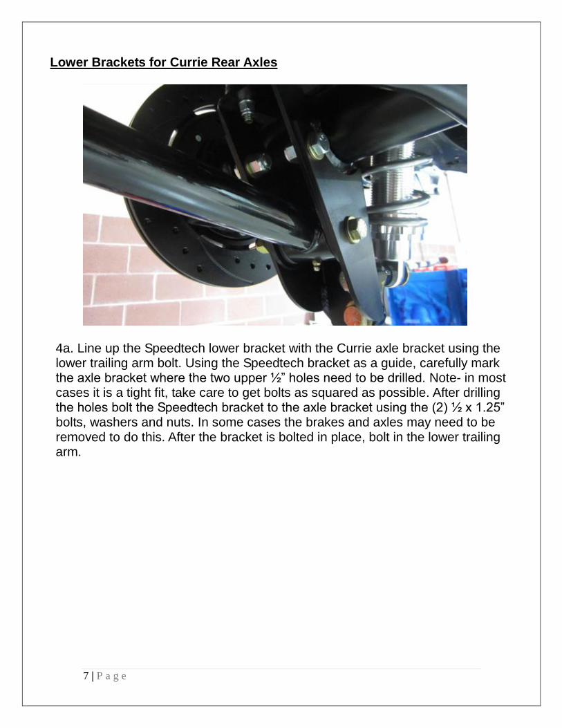
Lower Brackets for Currie Rear Axles
4a. Line up the Speedtech lower bracket with the Currie axle bracket using the lower trailing arm bolt. Using the Speedtech bracket as a guide, carefully mark the axle bracket where the two upper ½” holes need to be drilled. Note- in most cases it is a tight fit, take care to get bolts as squared as possible. After drilling the holes bolt the Speedtech bracket to the axle bracket using the (2) ½ x 1.25” bolts, washers and nuts. In some cases the brakes and axles may need to be removed to do this. After the bracket is bolted in place, bolt in the lower trailing arm.

8 | P a g e
5. Install the billet shock mount adapter to the bracket using the 5/8 x 1” bolt. There are 2 possible positions to mount this adapter, each affecting ride height up or down. We recommend bolting the longer 5/8 x 4 1/2” bolt through the bottom hole as a starting point. If you want additional ride height lift, simply rotate the adapter vertically to move that longer bolt to the upper hole. Do not install the shock at this time.

9 | P a g e
Upper Bracket Installation 1964-65 Cars 6a. Using 5/16” bolts, washers and nuts, bolt the upper bracket into place through the original upper shock mount holes. Using the 5/16” holes in the Speedtech bracket as a guide, drill two 5/16” holes in the frame. Bolt down the bracket using the 5/16” bolts, washers, and nuts. DO NOT skip this step, as all 4 bolts are necessary to keep the bracket securely mounted. See diagram below.
7a. Install your shocks. Be sure the 1/2” inside diameter bolt sleeve is located in the top and the 5/8” inside diameter bolt sleeve is located in the bottom of the shock.

10 | P a g e
1966-1972 Cars 6b. Place the upper bracket up into position using the factory upper shock mount holes to align the bracket. Using the Speedtech bracket as a guide, carefully mark the frame where the side 5/16” and 3rd 5/16” upper hole will need to be drilled. Drill the upper hole to 5/16”.

11 | P a g e
Drill the side hole to 5/16”.
7b. For the 66-72 cars, you will find it is easier to bolt the shock to the upper bracket first, and then install the assembly into the frame. Make sure the ½ x 2½” upper shock mount bolt points towards the front of the car. Using the 5/16” bolts and associated washers and nuts, install the bracket onto the frame.

12 | P a g e
Shock Assembly Diagram

13 | P a g e
7. Once all parts are installed in position, double check to see that all bolts are tight. Repeat this process for the other side. 9. With the weight off the rear suspension, support the rear axle and set the initial ride height according to shock manufacturer instructions. Replace wheels and tires and carefully lower the vehicle back onto the ground. Now you can fine tune your ride height adjustments. Because you have used factory mounting points as a base for this kit a wheel alignment may not be necessary. If you have installed adjustable trailing arms and/or changed front suspension components at the same time we do recommend having an alignment performed by a reputable source familiar with performance based alignments on older vehicles. On the following page you will find baseline specs for a performance Pro Touring type alignment. We do not recommend using alignment shop preprogrammed alignment specs for a performance handling vehicle.

14 | P a g e
Note: These are only suggestions and may need additional changes to achieve the optimum settings for your driving style or situation. Daily Driving, Street Performance Specifications
Driver Side Passenger Side
4 Degrees positive Caster 4 ½ Degrees positive Caster
0 to ½ Degree negative Camber 0 to ½ Degree negative Camber
3/ 32 Total Toe-in 3/ 32 Total Toe-in
Aggressive Track Alignment Specifications
Driver Side Passenger Side
5 ½ Degrees positive Caster 6 Degrees positive Caster
½ to 1 Degree negative Camber ½ to 1 Degree negative Camber
3/ 32 Total Toe-in 3/ 32 Total Toe-in
Original Specifications. **For reference purposes only. Do Not use these.
Driver Side Passenger Side
½ Degree positive Caster ½ Degree positive Caster
¼ to ½ Degree negative Camber ¼ to ½ Degree negative Camber
1/8 Total Toe-in 1/8 Total Toe-in

15 | P a g e
Speedtech performance USA LLC 1-435-628-4300
www.speedtechperformance.com Copyright Sppedtech Performance USA, LLC 2014

16 | P a g e
Terms and Conditions of Sale 1. Effective January, 2008, supersedes all previous policy statements. Policies are subject to change without notice. Speed tech performance Ltd. is not responsible for printing errors. 2. Speed Tech Performance Ltd. does not endorse, nor recommend modification of vehicles for use on public highways, since warranty or government regulations may be violated. As an express condition of sale of any performance part, the buyer acknowledges and agrees to use the performance parts for the modification of vehicles in sanctioned OFF-ROAD competitive events and show purposes only. Customers should exercise their discretion on matters with regards to the purchase and installation of these products. 3. Speed Tech Performance Ltd. does not ensure the legal use of these products. We do not guarantee the fitment of these products for anything other than there intended application nor do we assume any responsibilities what so ever for the misuse or losses incurred by the use of any of these components. While every effort is made to provide technical information and assistance, we have no control over owner installation, modification, and unusual stress that performance parts are subject to. 4. The customer acknowledges that Speed Tech Performance Ltd. and its employees are not responsible for any mechanical failures due to the use of parts sold, supplied or installed not for their intended application. Speed Tech Performance Ltd will not be held liable for any damages which are incurred directly or indirectly on the vehicles or operators or passengers of the vehicle 5. Please consult your sales agent and/or technician prior to purchase of any of Speed Tech Performance Ltd. Products to ensure proper fit. The buyer assumes all responsibilities for determining the suitability of the product. All aftermarket products should always be installed by professionals only. Warranty Claim: 1. Speed tech Performance Ltd. Warrants its products against materials and workmanship failure for the term of 12 months (1 year) from the date of purchase and only up to the amount paid with proof of purchase. 2. Seller’s liability shall as limited to repairing or replacing, at its option, any defective product which is returned, freight prepaid to Seller, according to the Merchandise Return Procedure set forth in Section 3 below. Buyer shall bear all responsibility for shipping charges and risk of loss or damage during transit to Seller. Products which have been subjected to abuse, misuse, alteration, neglect or unauthorized repair or installation, as determined solely by Seller, are not covered by this warranty. Any alterations, addition, improvements or attachments to the product(s) not authorized in writing by the Seller shall be deemed to be a waiver of this warranty by Buyer and shall render this warranty null and void. Seller shall return repaired or replaced product(s) to Buyer, at its expense via regular ground service in Canada. Shipping charges by all other methods and to all other destinations shall be borne by Buyer. 3. Merchandise return procedure A. If you purchased your Speed tech performance ltd product from us or from an authorized dealer, you are covered by the terms of this policy. All claims however, must be submitted directly to Speed tech performance Ltd.
B. Call the customer service representative at 1-888-467-1625.
C. Provide the invoice number, date of purchase and reason for return
D. You will be assigned a Returned Goods Authorization Number (RGA). The package you return must show the RGA on the outside of the package, include the original invoice and be shipped prepaid to our facility. The part has to be in its original packaging materials and be in a resellable condition. For parts presenting signs of use, only warranty claims will be accepted.
E. Ship to seller, freight pre-paid and insured for replacement cost in original packaging.
F. Replacement or repair decision will be made when merchandise is received by seller. No advance replacement is available. How to File a Warranty Claim: The answer to ALL the following questions should be YES before contacting our Customer Service Department. Is the part appropriate to your application? Did you carefully and thoroughly read the instructions provided along with the part? Do you have the proof of purchase? Are you the original purchaser? Is the part unmodified and clean? Is the return date within 3 months from the purchase date? Is the reason for return a legitimate product defect? If the answer to all these questions is YES, please contact our Customer Service Department at 1-888-467-1625. You will be given a Returned Goods Authorization Number (RGA) valid for 30 days. You will also be asked to ship the part prepaid to our facility. All shipments MUST be prepaid, include the original invoice and show the RGA on the outside of the package, otherwise it will be refused. Please include a brief explanation letter in order to expedite the warranty analysis process. What doesn’t this Warranty Cover? The costs not covered by this warranty include but are not limited to: - Removal, installation, shipment and insurance costs.
- Improper installation or maintenance
- Misuse or abuse, negligence
- Damage to related components
- Normal wear and tear.
- Costs incurred due to down time of vehicle
- Alterations on the original design or unauthorized repairs. All warranties implied by law are limited in duration of this warranty. You have specific rights that may vary from state to state or Province to Province. By purchasing any of the products that are manufactured by speed tech performance you agree to any and all of the above terms and conditions. Copyright © Speedtech Performance USA LLC