7013540r4 8000dh direct heat incubators · marking of electrical and electronic equipment, which...
TRANSCRIPT

Visit us online to register your warrantywww.thermoscientific.com/labwarranty
User M
anual
Series 8000DHCO2 IncubatorDirect Heat with Sterilization CycleOperating and Maintenance Manuals 7013540 Rev. 4

Thermo ScientificThermo Scientific
Preface
Direct Heat CO2 Incubator i
Model Sensor* Voltage**
3540 T/C 115
3541 T/C 230
3542 IR 115
3543 IR 230
*T/C is a thermal conductivity sensor. IR is an infra-red sensor.
**All units are 50/60 Hz.
MANUAL NUMBER 7013540
4 31343/IN-4592 10/22/14 New magnetic door switch (parts list, expl dwg, elec schematics) RoHS ccs
3 29174/IN-4469 3/5/14 Updated solenoid - pgs 8-5 & 9-1 through 9-3 ccs
2 30384/IN-4435 1/7/14 Added SRO ext door part number 1900567 to parts list ccs
1 24851, 24849/IN-3971 1/7/10 CO2 valve connection inlet & inner door switch kits-parts list & drawing 370-200-5 ccs
0 25694/IN-3954 10/26/09 Release level 2 - added spring rod kit (pg. 1-7) ccs
REV ECR/ECN DATE DESCRIPTION By

Thermo Scientificii Direct Heat CO2 Incubator Thermo Scientific
Preface
Contains Parts and Assemblies
Susceptible to Damage by
Electrostatic Discharge (ESD)
CAUTION
Important Read this instruction manual. Failure to read, understand and follow the instructions in this manualmay result in damage to the unit, injury to operating personnel, and poor equipment performance. s
Caution All internal adjustments and maintenance must be performed by qualified service personnel. s
Material in this manual is for information purposes only. The contents and the product it describes are subjectto change without notice. Thermo Fisher Scientific makes no representations or warranties with respect to thismanual. In no event shall Thermo be held liable for any damages, direct or incidental, arising out of or related tothe use of this manual.
Warning If the incubator is not used in the manner specified in this operating manual, the protection providedby the equipment design may be impaired. s
©2007 Thermo Scientific. All rights reserved.

Thermo Scientific Direct Heat CO2 Incubator iiiThermo Scientific
Preface
Important operating and/or maintenance instructions. Read the accompanying text carefully.
Potential electrical hazards. Only qualified persons should perform procedures associated with thissymbol.
Equipment being maintained or serviced must be turned off and locked off to prevent possible injury.
Hot surface(s) present which may cause burns to unprotected skin, or to materials which may bedamaged by elevated temperatures.
Marking of electrical and electronic equipment, which applies to electrical and electronic equipmentfalling under the Directive 2002/96/EC (WEEE) and the equipment that has been put on the marketafter 13 August 2005.
This product is required to comply with the European Union’s Waste Electrical & ElectronicEquipment (WEEE) Directive 2002/96/EC. It is marked with the WEEE symbol. Thermo FisherScientific has contracted with one or more recycling/disposal companies in each EU Member StateEuropean Country, and this product should be disposed of or recycled through them. Furtherinformation on Thermo’s compliance with this directive, the recyclers in your country andinformation on Thermo Scientific products will be available at www.thermofisher.com.
4 Always use the proper protective equipment (clothing, gloves, goggles, etc.)
4 Always dissipate extreme cold or heat and wear protective clothing.
4 Always follow good hygiene practices.
4 Each individual is responsible for his or her own safety.

Thermo Scientificiv Direct Heat CO2 Incubator Thermo Scientific
Preface
Do You Need Information or Assistance on
Thermo Scientific Products?
If you do, please contact us 8:00 a.m. to 6:00 p.m. (Eastern Time) at:
1-740-373-4763 Direct
1-800-438-4851 Toll Free, U.S. and Canada
1-877-213-8051 FAX
http://www.thermoscientific.com Internet Worldwide Web Home Page
[email protected] Tech Support Email Address
Certified Service Web Page
Thermo Fisher Scientific
401 Millcreek Road, Box 649
Marietta, OH 45750
Our staff can provide information on pricing and give you quotations. We can
take your order and provide delivery information on major equipment items or make
arrangements to have your local sales representative contact you. Our products are listed on the
Internet and we can be contacted through our Internet home page.
Our staff can supply technical information about proper setup, operation or
troubleshooting of your equipment. We can fill your needs for spare or replacement parts or
provide you with on-site service. We can also provide you with a quotation on our Extended
Warranty for your Thermo Scientific products.
Whatever Thermo Scientific products you need or use, we will be happy to discuss your
applications. If you are experiencing technical problems, working together, we will help you
locate the problem and, chances are, correct it yourself...over the telephone without a service
call.
When more extensive service is necessary, we will assist you with direct factory trained
technicians or a qualified service organization for on-the-spot repair. If your service need is
covered by the warranty, we will arrange for the unit to be repaired at our expense and to your
satisfaction.
Regardless of your needs, our professional telephone technicians are available to assist you
Monday through Friday from 8:00 a.m. to 6:00 p.m. Eastern Time. Please contact us by
telephone or fax. If you wish to write, our mailing address is:
International customers, please contact your local Thermo Scientific distributor.
Sales Support
Service Support
www.unitylabservices.com

Thermo Scientific Direct Heat CO2 Incubator vThermo Scientific
Preface
Warranty Notes
Information You Should Know Before Requesting Warranty Service
• Locate the model and serial numbers. A serial tag is located on the unit itself.
• For equipment service or maintenance, or with technical or special application inquiries, contact your local distributor.
Repairs NOT Covered Under Warranty
• Calibration of control parameters. Nominal calibrations are performed at the factory; typically ±1°C fortemperature, ±1% for gases, and ±5% for humidity. Our service personnel can provide precise calibrations asa billable service at your location. Calibration after a warranty repair is covered under the warranty.
• Damage resulting from use of improper quality water, chemicals or cleaning agents detrimental toequipment materials.
• Service calls for improper installation or operating instructions. Corrections to any of the following are billable services:
1) electrical service connection
2) tubing connections
3) gas regulators
4) gas tanks
5) unit leveling
6) room ventilation
7) adverse ambient temperature fluctuations
8) any repair external to the unit
• Damage resulting from accident, alteration, misuse, abuse, fire, flood, acts of God, or improperinstallation.
• Repairs to parts or systems resulting from unauthorized unit modifications.
• Any labor costs other than that specified during the parts and labor warranty period, which mayinclude additional warranty on CO2 sensors, blower motors, water jackets, etc.


Direct Heat CO2 Incubator viThermo Scientific
Table of Contents
Installation and Start-Up . . . . . . . . . . . . . . . . . . . . . . . . . . . . . . . . . . . . . .1-1Keypad Operation . . . . . . . . . . . . . . . . . . . . . . . . . . . . . . . . . . . . . .1-3Displays . . . . . . . . . . . . . . . . . . . . . . . . . . . . . . . . . . . . . . . . . . . . .1-4Installing the Incubator . . . . . . . . . . . . . . . . . . . . . . . . . . . . . . . . . .1-4Stacking the Incubators . . . . . . . . . . . . . . . . . . . . . . . . . . . . . . . . . .1-5Preliminary Cleaning . . . . . . . . . . . . . . . . . . . . . . . . . . . . . . . . . . .1-6Duct Sheets and Shelf Installation . . . . . . . . . . . . . . . . . . . . . . . . .1-7Access Port Filter & CO2 Sensor Cover Plate . . . . . . . . . . . . . . . . .1-9Air Sample Filter Installation . . . . . . . . . . . . . . . . . . . . . . . . . . . . .1-9HEPA Filter Installation . . . . . . . . . . . . . . . . . . . . . . . . . . . . . . . .1-10Leveling the Unit . . . . . . . . . . . . . . . . . . . . . . . . . . . . . . . . . . . . .1-10Electrical Power Connection . . . . . . . . . . . . . . . . . . . . . . . . . . . . .1-10Filling the Humidity Pan . . . . . . . . . . . . . . . . . . . . . . . . . . . . . . .1-11Connecting the CO2 Gas Supply . . . . . . . . . . . . . . . . . . . . . . . . .1-12Incubator Start-Up . . . . . . . . . . . . . . . . . . . . . . . . . . . . . . . . . . . .1-13
Calibration . . . . . . . . . . . . . . . . . . . . . . . . . . . . . . . . . . . . . . . . . . . . . . . . . .2-1Temperature . . . . . . . . . . . . . . . . . . . . . . . . . . . . . . . . . . . . . . . . . .2-1Thermal Conductivity CO2 System . . . . . . . . . . . . . . . . . . . . . . . .2-2Infrared CO2 System . . . . . . . . . . . . . . . . . . . . . . . . . . . . . . . . . . .2-3Relative Humidity . . . . . . . . . . . . . . . . . . . . . . . . . . . . . . . . . . . . . .2-4
Section 1
Section 2

vii Direct Heat CO2 Incubator Thermo Scientific
Configuration . . . . . . . . . . . . . . . . . . . . . . . . . . . . . . . . . . . . . . . . . . . . . . . .3-1Turn Audible Alarm ON/OFF . . . . . . . . . . . . . . . . . . . . . . . . . . . .3-1New HEPA Filter . . . . . . . . . . . . . . . . . . . . . . . . . . . . . . . . . . . . . .3-1Set REPLACE HEPA filter reminder . . . . . . . . . . . . . . . . . . . . . . .3-2Set Access Code . . . . . . . . . . . . . . . . . . . . . . . . . . . . . . . . . . . . . . .3-2Enable Low Temp Alarm to Trip Contacts . . . . . . . . . . . . . . . . . . .3-3Set Low Temp Alarm Limit (tracking alarm) . . . . . . . . . . . . . . . . .3-3Set High CO2 Alarm Limit (tracking alarm) . . . . . . . . . . . . . . . . .3-4Set Low CO2 Alarm Limit (tracking alarm) . . . . . . . . . . . . . . . . .3-4Set New Zero Number for T/C CO2 Sensors . . . . . . . . . . . . . . . .3-5Enable CO2 Alarms to Trip Contacts . . . . . . . . . . . . . . . . . . . . . . .3-5Setting a Low RH Alarm Limit . . . . . . . . . . . . . . . . . . . . . . . . . . . .3-6Set New Span Number for T/C CO2 Sensors . . . . . . . . . . . . . . . .3-6Enabling Temp/RH to be Displayed . . . . . . . . . . . . . . . . . . . . . . .3-7Enable RH Alarms to Trip Contacts . . . . . . . . . . . . . . . . . . . . . . . .3-7
Alarms . . . . . . . . . . . . . . . . . . . . . . . . . . . . . . . . . . . . . . . . . . . . . . . . . . . . . .4-1Sensor Fault Alarms . . . . . . . . . . . . . . . . . . . . . . . . . . . . . . . . . . . .4-2Temp Controller Failure . . . . . . . . . . . . . . . . . . . . . . . . . . . . . . .4-2TMP CNTR ERR . . . . . . . . . . . . . . . . . . . . . . . . . . . . . . . . . . . . .4-2
Routine Maintenance . . . . . . . . . . . . . . . . . . . . . . . . . . . . . . . . . . . . . . . . .5-1Clean Cabinet Exterior . . . . . . . . . . . . . . . . . . . . . . . . . . . . . . . . . .5-2Replace Power Fuses . . . . . . . . . . . . . . . . . . . . . . . . . . . . . . . . . . . .5-3HEPA Filter Maintenance . . . . . . . . . . . . . . . . . . . . . . . . . . . . . . . .5-3Clean Glass Doors . . . . . . . . . . . . . . . . . . . . . . . . . . . . . . . . . . . . .5-3Clean Humidity Pan . . . . . . . . . . . . . . . . . . . . . . . . . . . . . . . . . . . .5-3Replace Air Sample Filter . . . . . . . . . . . . . . . . . . . . . . . . . . . . . . . .5-4Electronics Section . . . . . . . . . . . . . . . . . . . . . . . . . . . . . . . . . . . . .5-4Sterilization Cycle . . . . . . . . . . . . . . . . . . . . . . . . . . . . . . . . . . . . . . . . . .5-6Sterilization Cycle . . . . . . . . . . . . . . . . . . . . . . . . . . . . . . . . . . . . . .5-8
Table of Contents
Section 3
Section 4
Section 5

Factory Options . . . . . . . . . . . . . . . . . . . . . . . . . . . . . . . . . . . . . . . . . . . . . .6-1Remote Alarms . . . . . . . . . . . . . . . . . . . . . . . . . . . . . . . . . . . . . . . .6-1Humidity Readout . . . . . . . . . . . . . . . . . . . . . . . . . . . . . . . . . . . . .6-2
Specifications . . . . . . . . . . . . . . . . . . . . . . . . . . . . . . . . . . . . . . . . . . . . . . .7-1
Spare Parts . . . . . . . . . . . . . . . . . . . . . . . . . . . . . . . . . . . . . . . . . . . . . . . . . .8-1Exploded Part Drawings . . . . . . . . . . . . . . . . . . . . . . . . . . . . . . . . . .8-2
Electrical Schematics . . . . . . . . . . . . . . . . . . . . . . . . . . . . . . . . . . . . . . . .9-1
Warranty Information . . . . . . . . . . . . . . . . . . . . . . . . . . . . . . . . . . . . . . . .10-1
Direct Heat CO2 Incubator viiiThermo Scientific
Table of Contents
Section 6
Section 8
Section 7
Section 9
Section 10


Direct Heat CO2 Incubator 1-1Thermo Scientific
Section 1 Installation and Start-Up
• Chamber Gas Sample Port - Used for sampling chamber CO2 contentusing a FYRITE or similar instrument.
• Main Power Switch - Mains Disconnect
• Control Panel - Keypad, displays & indicators (Figure 1-2)
• Leveling Legs - Used to level the unit
• Sterilization Cycle Button - Switch to initiate sterilization cycle
Note The incubators are stackable. Information follows. s
Inner Door
Leveling
Legs (4)
Door Heater
Cable
Control PanelChamber Gas
Sample Port
PowerSwitch
See Section 5
See
Section 1
Sterilization
Cycle ButtonSteri
Cycle
Figure 1-1. Components

1-2 Direct Heat CO2 Incubator Thermo Scientific
Section 1Installation and Start-Up
- Mutes the audible alarm. Alarm Indicator - Light pulses on/off during an alarm condition. MODE Select Switch - Used to select Run, Setpoints, Calibration and
Configuration modes. Message Display - Shows system status. Mode Select Indicators -
RUN: Run MenuSET: Set Points MenuCAL: Calibration MenuCON: Configuration Menu
HEAT Indicator - Lights when heaters are activated.INJ Indicator - Lights during CO2 injection into chamber.T (°C) Display - Programmable to display temperature. See
Configuration section.RH (%) Display - Shows percentage of humidity. See Configuration sec-
tion.CO2 (%) Display - Programmable to display CO2 percentage. See
Configuration section.Arrow Keys (Scroll for Parameters) - Increases or decreases number val-
ues, toggles between mode choices. ENTER - Stores the selected value into unit memory.
Figure 1-2. Control Panel
Power Switch
Mode SelectorSwitch
AlarmIndicator
SilenceSwitch
Mode Select Indicators
Scroll Arrow Keys
ENTERbutton
Active Heat Indicator
Active Injection Indicator
Temperaturein °C
Humidity in %
CO2 level in %
Message Display

Direct Heat CO2 Incubator 1-3Thermo Scientific
Section 1Installation and Start-Up
The Series 8000DH incubator has four basic modes for incubator setup:Run, Setpoints, Calibration and Configuration.
• Run is the default mode for normal operation.
• Set is used to enter system setpoints for incubator operation.
• Calibration is used to calibrate various system parameters.
• Configuration allows for custom setup of various options.
Table 1-1. Selections Under Each Mode
Keypad Operation
RUN SETPOINT CALIBRATION CONFIGURATION
Default Mode Temperature Temp Offset Audible
Overtemp CO2 Cal1 New HEPA Timer
CO2 IR Cal2 Replace HEPA Reminder
RH Cal Access Code
Temp Lo Alarm
Temp Relay
CO2 Lo Alarm
CO2 Hi Alarm
CO2 Relay
CO2 Z & S #'s *
RH Lo Alarm
RH Relay
Display Temp
Display RH
1 T/C units Base Unit Displays2 IR units Option Unit Displays*T/C units only

Installing theIncubator
SCROLL FOR PARAMETERS Arrows: Steps the operator throughparameters of SET, CAL and CON modes. The right arrow goes to thenext parameter, the left arrow returns to the previous parameter.
Up/Down Arrows: Increases/decreases or toggles the parameter valueselected in SET, CAL, and CON modes.
ENTER: Must press this key to save-to-memory all changed values.Key: Press to mute audible alarm. See Section 4 for alarm ringback
times.
Message Display: Shows system status (Mode) at all times. Shows ‘CLASS100’ or ‘SYSTEM OK’ during normal operation, or alarm messages ifthe system detects an alarm condition (see Section 4, Alarms). The mes-sage ‘CLASS 100’ is a timing mechanism indicating that, under normaloperating conditions with the HEPA filter installed, the air inside thechamber meets the Class 100 air cleanliness standard for particulates of0.5 micron size or larger per cubic foot of air. Further information onthe Class 100 classification of air quality is available from Thermo.
Upper and Lower Displays: The 7 segment upper display shows temp andRH. The lower display shows CO2 and O2.
1. Maintain a minimum three inch clearance behind the incubator forelectrical and gas hook-ups. In addition, a three inch ventilation spaceis needed on each side.
2. Locate the unit on a firm level surface capable of supporting the unitweight of 260 lbs (118kg).
3. Locate the unit away from doors and windows and heating and airconditioning ducts.
4. Lift the unit by the sides of the cabinet base. Do not attempt to lift itby the front and back. This places stress on the outer door hinges.
1-4 Direct Heat CO2 Incubator Thermo Scientific
Section 1Installation and Start-Up
Displays
Keypad Operation(continued)

Stacking theIncubators
Warning Install stacked units against a wall or similar structure. s
Warning With incubators in a stacked configuration, do not leave bothexterior doors open at the same time. s
Warning If the units have been in operation, turn them both off anddisconnect the power source before beginning any service work. s
Two stacking brackets (shown at left) are included in theparts bag shipped with each incubator.
1. Remove the cover plate securing the door cord from the incubator tobe on top. See Figure 1-4. Disconnect the plug from the connector.
2. Remove the four screws securing the door hinges to the unit. Removethe door and set it aside.
3. Unscrew the two hole plugs from the top cover of the incubator to bethe bottom of the stack (Figure 1-5).
4. Unscrew and remove the 4 leveling feet fromthe unit to be stacked on top and lift it ontothe bottom unit. Align all sides.
Warning This incubator weighs 260 lbs (118kg).Have sufficient personnel available when lifting.Lift the unit by the sides of the cabinet base toavoid placing stress on the outer door hinge. s
Direct Heat CO2 Incubator 1-5Thermo Scientific
Section 1Installation and Start-Up
Figure 1-4. Cover Plate
Figure 1-6. Stacked
Cover plate and bolt hole
with door connector
Figure 1-3. Stacking Brackets
Figure 1-5. Hole Plug Locations

5. Insert the stacking brackets into the slots at the back of the stackedunits as shown in Figure 1-7.
6. Align the slotted holes in the brackets with the mounting holes on theback of the top incubator. Secure the brackets with the screws andwashers provided in the parts bag. See Figure 1-8.
7. Thread one 1/4 x 20 bolt and washerincluded with the stacking brackets,into the hole behind the cover plate.Do not tighten. Refer to Figure 1-9.
8. Remove the cover plate from the samearea on the other side of the top unit.
9. Thread the other 1/4 x 20 bolt andwasher into this hole.
10. Tighten the bolts on both sides.
11. Assemble the door hinges to the unit. Secure with the screws.
12. Plug the door cord into the connector, as previously. Secure the coverplate.
13. Install the cover plate on the other side of the unit. The stackedincubators are ready for service.
1. Remove vinyl from shelf channels, duct sheets, and air duct, if present.
2. Using a suitable laboratory disinfectant, clean all interior surfaces.
Caution Before using any cleaning or decontamination method exceptthose recommended by the manufacturer, users should check with themanufacturer that the proposed method will not damage the equipment.Accidental spills of hazardous materials on or inside this unit are theresponsibility of the user. s
1-6 Direct Heat CO2 Incubator Thermo Scientific
Section 1Installation and Start-Up
Figure 1-8. Installed Brackets on Back of Unit
Stacking
bracket
Stacking
bracket
Bottom incubator back
Top incubator back
Top unitBottom unit
Figure 1-7. Bracketinto Slot
Cover plate and bolt hole
with door connector
Figure 1-9. Bolt Hole
Preliminary Cleaning
Stacking theIncubators (cont.)

1. Installed included grommets inot the backflange of each duct sheet; 6 grommets persheet. See Figure 1-10.
2. Install the side ducts with the tabs facing intothe center of the chamber with their slots up.There are no right side or left side ducts,simply rotate one of them to fit the oppositeside. Tilt the side ducts as they are placed intothe chamber so the tops fit into the top airduct, then guide them into the vertical position.Figure 1-11 shows the side duct as it would beoriented for the right side of the chamber.
3. Referring to Figure 1-11, note that there is no difference in the leftand right shelf channels.
4. Install the shelf channels by placing the channel’s rear slot over theappropriate rear tab on the side duct. Pull the shelf channel forwardand engage the channel’s front slot into the side duct’s appropriateforward tab. Refer to Figure 1-12.
5. Figure 1-11 shows one of the channels installed on the right side duct.
Direct Heat CO2 Incubator 1-7Thermo Scientific
Section 1Installation and Start-Up
Duct Sheet and ShelfInstallation
Side Duct
Side toward side duct
Side toward shelf
Right Side Duct
with Shelf Channel Installed
Shelf Channels
Side ducttab
Shelf channelrear slot
Shelf channelfront slot
Side ducttab
Figure 1-11. Shelf Channels & Side Ducts Figure 1-12. Channels and Slots
Figure 1-10. Grommetson back of duct sheet

1-8 Direct Heat CO2 Incubator Thermo Scientific
Section 1Installation and Start-Up
6. Locate the supplied rod, spring and end pieces; 4 each. Assemble thespring to the rod by positioning the very end of the spring over theridge at the rod. Then press the spring to the opposite side. It shouldsnap into place. See Figures 1-13 and 1-14.
7. Slide end cap over spring(Figure 1-15).
Note When installing the rods, thespring end can be installed oneither side of the chamber. Theupper front rod is high in thechamber and the upper back rod islower to allow access to the accessport filter door. s
8. Install one end of the rod into the appropriate hole in the duct sheet.
9. Compress the spring (under the end cap) to insert the other end of therod into the hole in the duct sheet on the opposite side.
10. Figure 1-16 shows the fourrods installed.
Installing Duct Sheetsand Shelves (cont.)
Figure 1-15. Spring End
Figure 1-13. Spring End Figure 1-14. Spring Assemble to Rod
Springend
Ridge
Back wall of chamber
Front opening of chamber
Figure 1-16. Four Rods Installed in Chamber

Direct Heat CO2 Incubator 1-9Thermo Scientific
Section 1Installation ans Start-Up
Air Sample FilterInstallation
1. Locate the opening in the top left corner of the interior chamber.Remove the tape from the opening on the outside of the unit.
2. Locate the stopper with filter in the hardware bag. Lift the metal portcover and install the assembly in the opening inside the chamber. SeeFigure 1-17.
3. Also in the hardware bag is the CO2 sensor cover plate. Install, usingthe 1/4-turn fasteners. Refer to Figure 1-17 for the location.
1. Remove the filter from the shipping bag.
2. Install the air sample filter assembly to the black hose barb behind thetop duct.
3. Insert the other end of the filter assembly onto the metal tubing on thetop duct. Refer to the Figure 1-18.
Access Port Filter &CO2 Sensor Cover Plate
Figure 1-17. Filter and Plate
Figure 1-18. Air Sample Filter Installation

Caution Be careful when the filter. The media can be damaged if it ismishandled. To avoid damage to the incubator, do not operate the unitwithout the HEPA filter in place. s
1. Remove the filter from the shipping box.
2. Remove the plastic coating from the filter, using caution not to touchthe filter media.
3. Install the filter as shown in Figure 1-18. Refer to Section 5 for HEPAfilter maintenance.
Caution The media of the filter can be damaged if mishandled. To avoid damage to the incubator, do not operate the unit without theHEPA filter in place. s
Check the unit for being level by placing a bubble-style level on one of theshelves. Turn the hex nut on the leveler counterclockwise to lengthen theleg or clockwise to shorten it. Level the unit front-to-back and left-to-right.
See the serial tag on the side of the unit for electrical specifications or referto the electrical schematics at the end of this manual.
Caution Serial tag rating is based on amperage draw during sterilizationcycle. Normal operating amperage is much less. Ensure that electricalcircuit will handle amp draw of sterilization cycle.Connect the incubator to a grounded, dedicated circuit. The power cordconnector is the mains disconnect device for the incubator. Position theunit so that it can be easily disconnected. s
1-10 Direct Heat CO2 Incubator Thermo Scientific
Section 1Installation and Start-Up
Electrical PowerConnection
Leveling the Unit
HEPA FilterInstallation

Direct Heat CO2 Incubator 1-11Thermo Scientific
Section 1Installation and Start-Up
Plug the provided power cord into the power inlet connector on the backof the cabinet (Figure 1-19), then into the grounded, dedicated, electricalcircuit.
Fill the humidity pan with sterile distilled water to within 1/2” of the top.Place the pan directly in the center of the incubator floor.
For applications requiring high humidity, the pan should be placed againstthe left side wall of the incubator. The side ducts have been modified toallow the pan to be placed against the wall. Optimum humidity is achievedby capping the CO2 sample port. This will, however, cause condensationin the chamber. To enhance RH recovery from door openings, place asecond humidity pan in the right side duct.
For best operation of the incubator, sterilized distilled, demineralized orde-ionized water should be used in the humidity pan. Water purity shouldbe in the resistance range of 50K to 1M Ohm/cm, or a conductivity rangeof 20.0 to 1.0 uS/cm. Refer to ASTM Standard D5391-93 or D4195-88for measuring water purity.
Distillation systems, as well as some types of reverse osmosis water puritysystems, can produce water in the quality range specified. Tap water is notrecommended as it may contain chlorine, which can deteriorate thestainless steel. Tap water may also have a high mineral content, whichwould produce a build-up of scale in the pan. High purity or ultra purewater is not recommended as it is an extremely aggressive solvent and willdeteriorate the stainless steel.
Filling the HumidityPan
���������� ���� �� �
�� ���
���������������� � ����
���� ������
�� ������ �������� !���"#$�%
���� ������
�� ������ �������� !���"#$�%
� �
a
b
RJ-ll telephone style connectors
IR CO units only2
CO Inlet
#1 Tank
2
aRemote
Alarm Contacts
30V max/1A max
bAir
Intake
Power Cord
Connector
Accessory
Outlet
75 watts max
Figure 1-19. Back of Cabinet
Electrical PowerConnection (cont.)
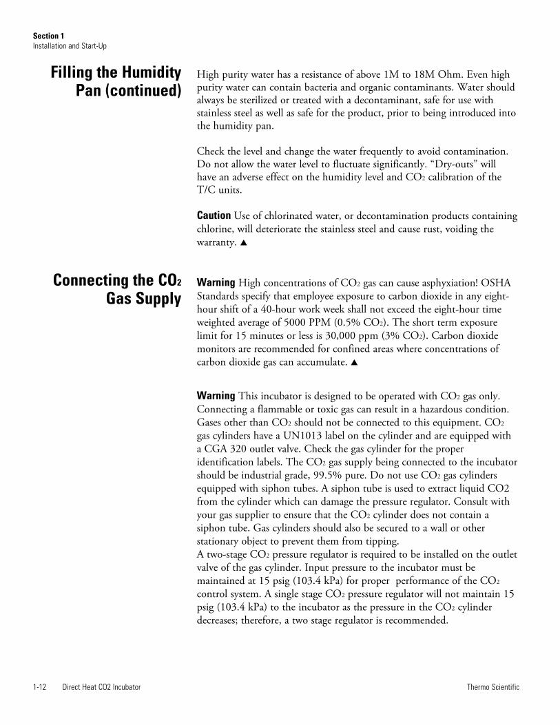
High purity water has a resistance of above 1M to 18M Ohm. Even highpurity water can contain bacteria and organic contaminants. Water shouldalways be sterilized or treated with a decontaminant, safe for use withstainless steel as well as safe for the product, prior to being introduced intothe humidity pan.
Check the level and change the water frequently to avoid contamination.Do not allow the water level to fluctuate significantly. “Dry-outs” willhave an adverse effect on the humidity level and CO2 calibration of theT/C units.
Caution Use of chlorinated water, or decontamination products containingchlorine, will deteriorate the stainless steel and cause rust, voiding thewarranty. s
Warning High concentrations of CO2 gas can cause asphyxiation! OSHAStandards specify that employee exposure to carbon dioxide in any eight-hour shift of a 40-hour work week shall not exceed the eight-hour timeweighted average of 5000 PPM (0.5% CO2). The short term exposurelimit for 15 minutes or less is 30,000 ppm (3% CO2). Carbon dioxidemonitors are recommended for confined areas where concentrations ofcarbon dioxide gas can accumulate. s
Warning This incubator is designed to be operated with CO2 gas only.Connecting a flammable or toxic gas can result in a hazardous condition.Gases other than CO2 should not be connected to this equipment. CO2
gas cylinders have a UN1013 label on the cylinder and are equipped witha CGA 320 outlet valve. Check the gas cylinder for the properidentification labels. The CO2 gas supply being connected to the incubatorshould be industrial grade, 99.5% pure. Do not use CO2 gas cylindersequipped with siphon tubes. A siphon tube is used to extract liquid CO2from the cylinder which can damage the pressure regulator. Consult withyour gas supplier to ensure that the CO2 cylinder does not contain asiphon tube. Gas cylinders should also be secured to a wall or otherstationary object to prevent them from tipping.A two-stage CO2 pressure regulator is required to be installed on the outletvalve of the gas cylinder. Input pressure to the incubator must bemaintained at 15 psig (103.4 kPa) for proper performance of the CO2
control system. A single stage CO2 pressure regulator will not maintain 15psig (103.4 kPa) to the incubator as the pressure in the CO2 cylinderdecreases; therefore, a two stage regulator is recommended.
Connecting the CO2
Gas Supply
1-12 Direct Heat CO2 Incubator Thermo Scientific
Section 1Installation and Start-Up
Filling the HumidityPan (continued)

Direct Heat CO2 Incubator 1-13Thermo Scientific
Section 1Installation and Start-Up
Incubator Start-Up
Warning If higher purity CO2 is desired inside the incubator (greater than99.5% pure), the pressure regulator should be constructed with a stainlesssteel diaphragm, along with specifying the purity of the CO2 from the gassupplier. Follow the manufacturer’s instructions to ensure proper and safeinstallation of the pressure regulator on the gas cylinder.Consult your facility safety officer to ensure that the equipment is installedin accordance with the codes and regulations that are applicable in yourarea. s
The CO2 gas supply being connected should be industrial grade 99.5%pure and should not contain siphon tubes. Install a two-stage pressureregulator at the cylinder outlet. The high pressure gauge at the tank shouldhave 0-2000 psig range. The low pressure gauge, at the incubator inlet,should have a 0-30 psig range. Input pressure to the incubator must bemaintained at 15 psig (103.4 kPa).
The incubator has serrated fittings on the back of the cabinet to connectthe gas supply. Refer to Figure 1-19. The fitting is labeled CO2 Inlet #1Tank. Make sure that the connections are secured with clamps. Check allfittings for leaks.
With the incubator properly installed and connected to power, thehumidity pan filled, and the unit connected to gas supplies, systemsetpoints can be entered. The following setpoints can be entered in SETmode: Temperature, Overtemperature and CO2. To enter SET mode,press the MODE key until the SET indicator lights. Press the rightand/or left arrow keys until the proper parameter appears in the messagedisplay. See Chart 1-1 for more detail.
All Series 8000DH incubators have an operating temperature range of10°C to 50°C, depending on ambient temperature. The incubator isshipped from the factory with a temperature setpoint of 10°C. At thissetting, all heaters are turned off.
Setting the OperatingTemperature
Connecting CO2 GasSupply (continued)

Setting the OvertempSetpoint
To change the operating temperature setpoint:
1. Press the MODE key until the SET indicator lights.
2. Press the right arrow until “Temp XX.X” is displayed in the messagedisplay.
3. Press the up/down arrow key until the desired temperature setpoint isdisplayed.
4. Press ENTER to save the setpoint.
5. Press the MODE key until the RUN indicator lights for RUN modeor press the right/left arrow keys to go to next/previous parameter.
Caution The independent overtemp system is designed as a safety toprotect the incubator only. It is not intended to protect or limit themaximum temperature of the cell cultures or customer’s equipment insidethe incubator if an overtemp condition occurs. s
Series 8000DH incubators are equipped with a secondary temperaturemonitoring system to monitor the air temperature inside the cabinet. Thissystem is designed as a safety device to turn off all heaters in the event of atemperature control failure. Temperature control in the incubator will be±1° of the overtemp setpoint.
The overtemperature is set by the factory (default) at 40°C. However, theovertemp can be set up to 55°C in 0.5° increments.
If the incubator’s operating temperature setpoint is set above the overtempsetpoint, the overtemp setpoint will automatically update to 1°C above thetemperature setpoint. It is recommended that the overtemp setpoint bemaintained at 1°C over the operating temperature setpoint.
1-14 Direct Heat CO2 Incubator Thermo Scientific
Section 1Installation and Start-Up
Setting the OperatingTemperature (continued)

Direct Heat CO2 Incubator 1-15Thermo Scientific
Section 1Installation and Start-Up
To set the Overtemp setpoint:
1. Press the MODE key until the SET indicator lights
2. Press the right arrow until Otemp XX.X is displayed in the messagedisplay
3. Press the up or down arrow key until the desired Overtemp setpoint isdisplayed
4. Press ENTER to save the setting
5. Press the MODE key until the RUN indicator lights or press the rightor left arrow to go to the next or previous parameter.
All T/C CO2 cells are calibrated at the factory at 37°C, high humidity,and 10% CO2. Therefore, if a temperature setpoint of 37°C has beenentered, the humidity pan has been filled and the CO2 control is to runbetween 0-10% with a T/C CO2 sensor, the CO2 setpoint may be enteredimmediately. Otherwise, it is important to allow the unit 12 hours tostabilize at the temperature setpoint before entering the CO2 setpoint.
Both models of the incubator have a CO2 setpoint range of 0.0% to20.0%. The incubator is shipped from the factory with a CO2 setpoint of0.0%. At this setting, all CO2 control and alarms are turned off. Tochange the CO2 setpoint:
1. Press the MODE key until the SET indicator lights.
2. Press the right arrow until “CO2 XX.X” is displayed in the messagedisplay.
3. Press the up/down arrows until the desired CO2 setpoint is displayed.
4. Press ENTER to save the setpoint.
5. Press the MODE key until the RUN indicator lights to go to RUNmode or press the right/left arrow keys to go to next/previousparameter.
Setting the OvertempSetpoint (continued)
Setting the CO2 Setpoint

1-16 Direct Heat CO2 Incubator Thermo Scientific
Section 1Installation and Start-Up

Direct Heat CO2 Incubator 2-1Thermo Scientific
Section 2 Calibration
After the unit has stabilized, several different systems can be calibrated. InCalibration mode, the air temperature, CO2 and RH levels can becalibrated to reference instruments. To access Calibration mode, press theMODE key until the CAL indicator lights. Press the right and/or leftarrow until the appropriate parameter appears in the message display. SeeChart 2-1 at the end of this section for more detail.
Calibration frequency is dependent on use, ambient conditions andaccuracy required. A good laboratory practice would require at least anannual calibration check. On new installations, all parameters should bechecked after the stabilization period.
Prior to calibration, the user should be aware of the following systemfunctions. While the unit is in Calibration mode, all system controlfunctions are stopped so the unit remains stable. Readout of the systembeing calibrated appears on the message display. If no keys are pressed forapproximately five minutes while in Calibration mode, the system resets toRUN mode so control functions are reactivated.
Caution Before making any calibration or adjustments to the unit, it isimperative that all reference instruments be properly calibrated. s
Before calibration, allow the cabinet temperature to stabilize. Place thecalibrated instrument in the center of the chamber. The instrumentshould be in the airflow, not against the shelf.
Temperature Stabilization Periods
Startup - Allow 12 hours for the temperature in the cabinet to stabilizebefore proceeding.
Already Operating - Allow at least 2 hours after the display reachessetpoint for temperature to stabilize before proceeding.
Temperature

2-2 Direct Heat CO2 Incubator Thermo Scientific
Section 2Calibration
1. Press the MODE key until CAL indicator lights.
2. Press the right arrow until “TEMPCAL XX.X” appears in the messagedisplay.
3. Press up/down arrow to match display to calibrated instrument.
4. Press ENTER to store calibration.
5. Press the MODE key to return to RUN or the right/left arrow to go tonext/previous parameter.
Models 3540 and 3541 have a thermal conductivity (T/C) CO2 sensor.Thermal conductivity of the incubator atmosphere is not only effected bythe quantity of CO2 present but also by the air temperature and watervapor present in the incubator atmosphere. In monitoring the effects ofCO2, air temperature and absolute humidity must be held constant so anychange in thermal conductivity is caused by a change in CO2
concentration.
Changing temperature or changing from elevated humidity to roomambient humidity levels will necessitate a re-calibration of the CO2
control.
Some T/C CO2 sensors go through an aging period, especially on newinstallations. Calibration should be checked on a weekly basis, andadjusted as necessary. When stabilization occurs, checks can become lessfrequent.
T/C CO2 Sensor Stabilization Periods
Start -Up - The CO2 sensor has been calibrated at the factory for 37°Cand elevated humidity. Allow the temperature, humidity, and CO2 levelsin the chamber to stabilize at least 12 hours before checking the CO2
concentration with an independent instrument.
Presently Operating - Make sure the chamber doors are closed. Allow atleast 2 hours after the temperature and CO2 displays reach their setpointsfor chamber atmosphere stabilization.
Temperature(continued)
Thermal ConductivityCO2 System

Direct Heat CO2 Incubator 2-3Thermo Scientific
Section 2Calibration
1. Make sure the stabilization periods outlined above are followed.
2. Sample the chamber atmosphere through the sample port with anindependent instrument. Sample the atmosphere at least 3 times toensure accuracy of the instrument.
3. Press the MODE key until the CAL indicator lights.
4. Press the right arrow until “CO2 CAL XX.X” is displayed in themessage display.
5. Press the up /down arrows to change the display to match theindependent instrument.
6. Press ENTER to store the calibration.
7. Press the MODE key to return to RUN or the right or left arrows togo to the next/ previous parameter.
Models 3542 and 3543 have an infrared (IR) CO2 sensor. Infrared CO2
sensors are not effected by chamber atmosphere temperature or humidity.However, the light detector in the sensor is effected by wide temperaturechanges. Therefore, changing temperature setpoints could necessitate arecalibration of the CO2. Chamber temperature should be allowed tostabilize before checking CO2 concentrations with an independentinstrument, especially on start-up.
IR CO2 Sensor Stabilization Times
Start-Up- Allow the temperature and the CO2 of the cabinet to stabilize atleast 12 hours before proceeding.
Presently Operating - Allow CO2 to stabilize at least 2 hours at setpointbefore proceeding.
Thermal ConductivityCO2 System (continued)
Infrared CO2 System

1. Measure the CO2 concentration in the chamber through the gassample port with a Fyrite or other independent instrument. Severalreadings should be taken to ensure accuracy.
2. Press the MODE key until the CAL indicator lights.
3. Press the right arrow until “IR CAL XX.X” appears in the messagedisplay.
4. Press the up/down arrow to adjust the display to match theindependent instrument reading.
5. Press ENTER to store the calibration.
6. Press the MODE key to return to RUN mode.
Model 3540 and 3541 incubators are equipped with an optional direct-readout relative humidity sensor. This is a readout only of the chamberrelative humidity level. It does not provide any control of the relativehumidity in the cabinet.
Relative Humidity Stabilization Times
Start-Up - Allow 12 hours for the relative humidity and temperature in thechamber to stabilize before proceeding.
Already Operating - Allow at least 2 hours after temperature displayreaches setpoint for relative humidity to stabilize before proceeding.
1. Place an accurate independent instrument in the center of thechamber. Allow at least 30 minutes for RH to stabilize.
2. Press the MODE key until the CAL indicator lights.
3. Press the right arrow key until “RH CAL XX” appears in the messagedisplay.
4. Press the up/down arrow to match the display to the independentinstrument.
5. Press ENTER to store the calibration.
6. Press the MODE key to return to RUN mode.
2-4 Direct Heat CO2 Incubator Thermo Scientific
Section 2Calibration
Infrared CO2 System(continued)
Relative Humidity

If a reliable RH measuring device is not available, the display can becalibrated to a typical level;
1. Follow the RH stabilization periods outlined above.
2. With a full humidity pan and stable temperature, the relative humidityin the chamber will be 95%.
3. Using Step 3-5 of the relative humidity sensor adjustment, adjust thedisplay to 95%.
This calibration method should be accurate to within 5%.
Direct Heat CO2 Incubator 2-5Thermo Scientific
Section 2Calibration
Relative Humidity(continued)

2-6 Direct Heat CO2 Incubator Thermo Scientific
Section 2Calibration

Direct Heat CO2 Incubator 3-1Thermo Scientific
Section 3 Configuration
Several features available in Configuration mode allow custom setup of theincubator. These features are listed with descriptions below. All featuresmay not be necessary in all applications, but are available if needed. Toenter Configuration mode, press the MODE key until the CON indicatorlights. Press the right and/or left arrow until the appropriate parameterappears in the message display. See Chart 3-1 for more detail.
The audible alarm can be turned on or off. The factory setting is ON.
1. Press the MODE key until the CON indicator lights.
2. Press the right arrow until AUDIBLE XXX shows in the messagedisplay.
3. Press the up/down arrow to toggle AUDIBLE ON/OFF.
4. Press ENTER to save the setting.
5. Press the MODE key to return to RUN mode or right/left arrow to goto next/previous parameter.
When the REPLACE HEPA reminder displays and the visual alarmflashes, the specified time has elapsed and the HEPA filter should bereplaced. To clear the display and reset the timer after replacing the HEPAfilter with a new one, follow the steps below.
1. Press the MODE key until the CON indicator lights.
2. Press the right arrow until NEW HEPA shows in the message display.
3. Press ENTER to restart the timer and clear the REPLACE HEPAalarm.
4. Press the MODE key to return to RUN mode.
New HEPA Filter
Turn Audible AlarmON/OFF

Set Access Code
3-2 Direct Heat CO2 Incubator Thermo Scientific
Section 3Configuration
A HEPA filter replacement timer can be set for a specific amount of time,from 1 to 12 months of actual unit running time. Time will not accruewhen the unit is turned off. The default time is 6 months. When theallotted time runs out, REPLACE HEPA appears in the display and thevisual alarm flashes. To set the reminder, use the following procedure.
1. Press the MODE key until the CON indicator lights.
2. Press the right arrow until REPL HEPA XX is displayed.
3. Press the up/down arrow to choose the number of months desired.
4. Press ENTER to save the number.
5. Press the MODE key to return to RUN mode or right/left arrow to goto next/previous parameter.
Note After the reminder has been set, check the allotted time remaining bygoing to Configuration mode, then pressing the right arrow until NEWHEPA XXX displays. This number is the remaining days before the filterreplacement time specified runs out. For example, if 12 months was chosenin the REPL HEPA XX message display, the NEW HEPA number wouldbe 365 days. s
A 3-digit Access Code can be entered to avoid unauthorized personnelfrom changing the setpoints, calibration, or configuration. A setting of000 bypasses the access code. The factory setting is 000.
1. Press the MODE key until the CON indicator lights.
2. Press the right arrow until ACC CODE XXX shows in the messagedisplay.
3. Press up/down arrow to change the access code.
4. Press ENTER to save the access code.
5. Press the MODE key to return to the RUN mode or right/left arrowto go to next/previous parameter.
Set REPLACE HEPAfilter reminder

Direct Heat CO2 Incubator 3-3Thermo Scientific
Section 3Configuration
The low temp alarm limit is the deviation from the temperature setpointwhich causes a low temp alarm. The low temp alarm is variable from 0.5°below setpoint to 5° below setpoint. The factory setting is 1° belowsetpoint. A minus sign (-) in the display indicates that the alarm setting isbelow the setpoint.
1. Press the MODE key until the CON indicator lights.
2. Press the right arrow until TEMP LO -X.X shows in the messagedisplay.
3. Press up/down arrow to change the low temp alarm limit.
4. Press ENTER to save the low temp alarm limit.
5. Press the MODE key to return to RUN mode or right/left arrow to goto next/previous parameter.
The low temperature alarm can be programmed to trip the remote alarmcontacts. A setting of ON allows this, an OFF setting blocks the low tempalarm from tripping the contacts. The factory setting is ON.
1. Press the MODE key until the CON indicator lights.
2. Press the right arrow until TMP RLY XXX displays.
3. Press the up/down key to toggle the setting ON/OFF.
4. Press ENTER to save the setting
5. Press the MODE key to return to RUN mode, or the right/left arrowto go to next/previous parameter.
Set Low Temp AlarmLimit (tracking alarm)
Enable Low TempAlarm to Trip Contacts

The low CO2 alarm limit is the deviation from the CO2 setpoint whichwill cause a low CO2 alarm. The setpoint is variable from 0.5% CO2
below setpoint to 5.0% CO2 below setpoint. The factory setting is 1.0%CO2 below setpoint. A minus sign (-) in the display indicates that thealarm setting is below the setpoint.
1. Press the MODE key until the CON indicator lights.
2. Press the right arrow until CO2 LO -X.X shows in the messagedisplay.
3. Press up/down arrow to change the low CO2 alarm limit.
4. Press ENTER to save the low CO2 alarm limit.
5. Press the MODE key to return to RUN mode or right/left arrow to goto next/previous parameter.
The high CO2 alarm limit is the deviation from the CO2 setpoint whichwill cause a high CO2 alarm. The setpoint is variable from 0.5% CO2
above setpoint to 5.0% CO2 above setpoint. The factory setting is 1.0%CO2 above setpoint.
1. Press the MODE key until the CON indicator lights.
2. Press the right arrow until CO2 HI X.X shows in the message display.
3. Press up/down arrow to change the high CO2 alarm limit.
4. Press ENTER to save the high CO2 alarm limit.
5. Press the MODE key to return to RUN mode, or right/left arrow togo to next/previous parameter.
3-4 Direct Heat CO2 Incubator Thermo Scientific
Section 3Configuration
Set Low CO2 AlarmLimit (tracking alarm)
Set High CO2 AlarmLimit (tracking alarm)

High and Low CO2 alarms can be programmed to trip the remote alarmcontacts. A setting of ON allows this, a setting of OFF blocks CO2 alarmsfrom tripping the contacts. The factory setting is ON.
1. Press the MODE key until the CON indicator lights.
2. Press the right arrow until CO2 RLY XXX shows in the messagedisplay.
3. Press up/down arrow to toggle the setting ON/OFF.
4. Press ENTER to save the setting.
5. Press the MODE key to return to RUN mode or right/left arrow to goto next/previous parameter.
If a new T/C CO2 sensor is being installed, the two numbers on thefactory installed sticker on the T/C cell must be entered to calibrate CO2
in the unit.
Note For the technician’s convenience, a label containing the twonumbers on the T/C cell is affixed inside the electronics drawer. s
1. Press the MODE key until the CON indicator lights.
2. Press the right arrow until T/CZ# XXXX shows in the messagedisplay.
3. Press up/down arrow to change the zero number to match the sticker.
4. Press ENTER to save the setting.
5. Press the MODE key to return to RUN mode or right/left arrow to goto next/previous parameter.
Direct Heat CO2 Incubator 3-5Thermo Scientific
Section 3Configuration
Enable CO2 Alarms toTrip Contacts
Set New Zero Numberfor T/C CO2 Sensors

If a new T/C CO2 sensor is being installed, the two numbers on thefactory installed sticker on the T/C cell must be entered to calibrate theCO2 in the unit.
Note For the technician’s convenience, a label containing the two numberson the T/C cell is affixed inside the electronics drawer. s
1. Press the MODE key until the CON indicator lights.
2. Press the right arrow until T/CS# XXXX shows in the message display.
3. Press up/down arrow to change the span number to match the sticker.
4. Press ENTER to save the setting.
5. Press the MODE key to return to RUN mode or right/left arrow to goto next/previous parameter.
On units with the RH option installed, a low RH alarm limit may beentered. The low RH alarm limit is the %RH in the cabinet that causes alow RH alarm. The setpoint is variable from setpoint 0 to 90% RH. Thefactory setting is 0% RH, which disables the alarm.
1. Press the MODE key until the CON indicator lights.
2. Press the right arrow until RH LO XX shows in the message display.
3. Press up/down arrow to change the RH low alarm limit.
4. Press ENTER to save the RH low alarm limit.
5. Press the MODE key to return to RUN mode or right/left arrow to goto next/previous parameter.
3-6 Direct Heat CO2 Incubator Thermo Scientific
Section 3Configuration
Set New Span Numberfor T/C CO2 Sensors
Setting a Low RHAlarm Limit

The low RH alarm can be programmed to trip the remote alarm contacts.A setting of ON allows this, a setting of OFF blocks the RH alarm fromtripping the contacts. The factory setting is ON.
1. Press the MODE key until the CON indicator lights.
2. Press the right arrow until RH RLY XXX shows in the messagedisplay.
3. Press up/down arrow to toggle the setting ON/OFF.
4. Press ENTER to save the setting.
5. Press the MODE key to return to RUN mode or right/left arrow to goto next/previous parameter.
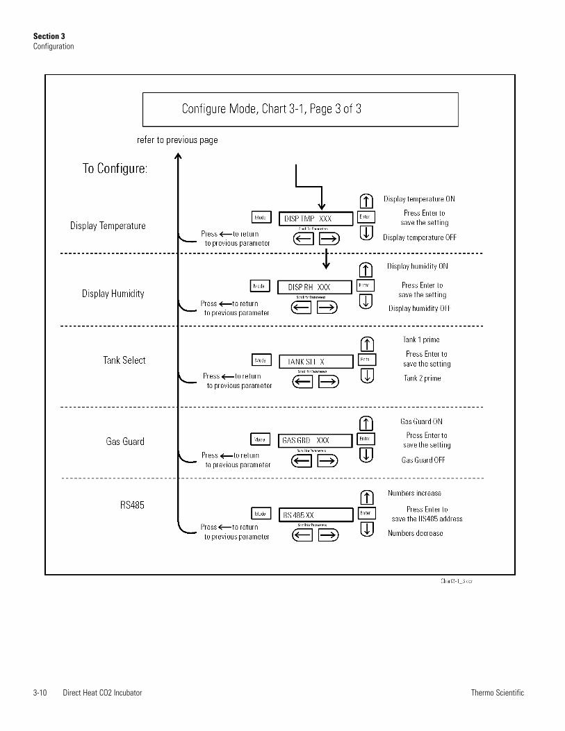
On units equipped with the RH option, the upper seven segment displayon the control panel can be configured to display Temp continuously, RHcontinuously, or toggle between Temp and RH. If the units does not haveRH, the upper display always shows temperature. If temperature is set toON, and the RH is set OFF, temperature shows continuously. Iftemperature is set to OFF and RH is set to ON, RH shows continuously.If both are turned ON, the display toggles between the two. The factorysetting defaults to toggle mode if the RH option is present.
1. Press the MODE key until the CON indicator lights.
2. Press the right arrow until DISP TMP XXX or DISP RH XXX showsin the message display.
3. Press up/down arrow to toggle the setting ON/OFF.
4. Press ENTER to save the setting.
5. Press the MODE key to return to RUN mode or right/left arrow to goto next/previous parameter.
Direct Heat CO2 Incubator 3-7Thermo Scientific
Section 3Configuration
Enable RH Alarms toTrip Contacts
Enabling Temp/RH tobe Displayed

3-8 Direct Heat CO2 Incubator Thermo Scientific
Section 3Configuration

Direct Heat CO2 Incubator 3-9Thermo Scientific
Section 3Configuration
3-10 Direct Heat CO2 Incubator Thermo Scientific
Section 3Configuration

Direct Heat CO2 Incubator 4-1Thermo Scientific
Section 4 Alarms
The Series 8000DH incubator alarm system is shown in the table below.When an alarm is active, the message appears in the LED message display.Pressing disables the audible alarm for the ringback period. However,the visual alarm continues until the incubator returns to a normalcondition. The alarms are momentary alarms only. When an alarmcondition occurs and then returns to normal, the incubator automaticallyclears the alarm condition and the message display.
When multiple alarm conditions occur, active messages are shown in themessage display one at a time, updating at 5 second intervals. Pressingduring multiple alarms causes all active alarms to be silenced and to ringback in 15 minutes.
The TEMP IS LOW alarm is disabled when the Temp set point is 10°C.The CO2 alarms are disabled when the CO2 set point is 0.0%.
Description Message Delay Ringback Relay
No alarm condition exists SYSTEM OK or CLASS 100 ----- ----- -----
Temp > Otemp Set point SYS IN OTEMP 0 min. 15 min. Yes
Air Temp Sensor Fault (See Section 4) AIR SNSR ERR 0 min. 15 min. No
Temperature Controller Failure (See Sect. 4) TMP CTRL ERR 0 min. 15 min. YES
CO2 Sensor Fault (See Section 4) CO2 SNSR ERR 0 min. 15 min. No
Replace HEPA filter reminder-set time expired(See Section 3) REPLACE HEPA 0 min. ----- No
Inner Door is Open DOOR OPEN 15 min. 15 min. No
CO2 is higher than CO2 High Tracking Alarm CO2 IS HIGH 15 min. 15 min. Programmable
CO2 is lower than CO2 Low Tracking Alarm CO2 IS LOW 15 min. 15 min. Programmable
TEMP is lower TEMP Low Tracking Alarm TEMP IS LOW 15 min. 15 min. Programmable
RH is lower than RH Low Limit Alarm (RH option) RH IS LOW 30 min. 15 min. Programmable
Table 4-1. Alarm and Description
- All alarm delays and ringback times are ±30 seconds -

4-2 Direct Heat CO2 Incubator Thermo Scientific
Section 4Alarms
Temp Controller Failure TMP CNTR ERR
In addition to other safety features designed into Series 8000DHincubators, a thermostat is provided to monitor the cabinet’s temperature.In the unlikely event of a temperature control failure, the thermostat willturn off all heaters at a cabinet temperature of 160°C, ±5%. This isintended to be a safety feature to protect the incubator, and is notintended to protect the cell cultures or the equipment inside the chambershould a temperature control failure occur. Should such a failure occur,contact the Technical Services Department or your local distributor.
The microprocessor in Series 8000DH incubators continually scans allavailable sensors to ensure that they are operating properly. Should an errorbe detected, the incubator sounds an alarm and shows the appropriatemessage. Contact your local distributor.
Sensor Fault Alarms

PREV
ENTI
VE M
AIN
TEN
AN
CE
Incu
bato
rs
Yo
ur e
quip
men
t has
bee
n th
orou
ghly
test
ed a
nd c
alib
rate
d be
fore
shi
pmen
t. Re
gula
r pre
vent
ive
mai
nten
ance
is im
porta
nt to
kee
p yo
ur
unit
func
tioni
ng p
rope
rly. T
he o
pera
tor s
houl
d pe
rform
rout
ine
clea
ning
and
mai
nten
ance
on
a re
gula
r bas
is. F
or m
axim
um p
erfo
rman
ce
and
effic
ienc
y, it
is re
com
men
ded
the
unit
be c
heck
ed a
nd c
alib
rate
d pe
riodi
cally
by
a qu
alifi
ed s
ervi
ce te
chni
cian
. Th
e fo
llow
ing
is a
con
dens
ed li
st o
f pre
vent
ive
mai
nten
ance
requ
irem
ents
. See
the
spec
ified
sec
tion
of th
e op
erat
ing
man
ual f
or fu
rther
de
tails
. W
e ha
ve q
ualif
ied
serv
ice
tech
nici
ans,
usi
ng N
IST
trace
able
inst
rum
ents
, ava
ilabl
e in
man
y ar
eas.
For
mor
e in
form
atio
n on
Pre
vent
ive
Mai
nten
ance
or E
xten
ded
War
rant
ies,
ple
ase
cont
act T
echn
ical
Ser
vice
s.
Clea
ning
and
cal
ibra
tion
adju
stm
ent i
nter
vals
are
dep
ende
nt u
pon
use,
env
ironm
enta
l con
ditio
ns a
nd a
ccur
acy
requ
ired.
Ti
ps fo
r all
incu
bato
rs:
Do
NOT
use
ble
ach
or a
ny d
isin
fect
ant t
hat h
as h
igh
chlo
ros
Us
e st
erile
, dis
tille
d or
dem
iner
alize
d w
ater
.
Avoi
d sp
rayi
ng c
lean
er o
n th
e CO
2 se
nsor
.
Do
not
use
pow
dere
d gl
oves
for t
issu
e cu
lture
s.

Prev
entiv
e M
aint
enan
ce fo
r Ser
ies
8000
DH In
cuba
tors
Ref
er to
Man
ual
Sect
ion
Act
ion
Dai
ly
Wee
kly
Mon
thly
3 to
6
Mon
ths
Yea
rly
--
Che
ck C
O2 t
ank
leve
ls.
--
Insp
ect d
oor l
atch
, hin
ges a
nd d
oor g
aske
t sea
l.
1 C
heck
wat
er le
vel i
n th
e hu
mid
ity p
an, ½
” fr
om to
p.
2 V
erify
and
doc
umen
t CO
2, hu
mid
ity a
nd te
mpe
ratu
re
calib
ratio
n, a
s app
licab
le (S
ee C
alib
ratio
n).
D
isinf
ect t
he in
terio
r of t
he in
cuba
tor (
See
Rou
tine
Mai
nten
ance
).
1 R
epla
ce H
EPA,
acc
ess p
ort f
ilter
, air
sam
ple
filte
r, an
d C
O2 f
ilter
s*, i
f app
licab
le (o
r as n
eede
d).
5 Pe
rform
ster
iliza
tion
cycl
e as
nee
ded.

Direct Heat CO2 Incubator 5-1Thermo Scientific
Section 5 Routine Maintenance
Warning If the unit has been in service, turn it off and disconnect thepower cord connector before proceeding with any maintenance. s
Caution Before using any cleaning method except those recommended bythe manufacturer, users must check with the manufacturer that theproposed method will not damage the equipment. s
Use an appropriate disinfectant. All articles and surfaces must bethoroughly cleaned, rinsed with sterile water, and rough-dried.
Warning Alcohol, even a 70% solution, is volatile and flammable. Use itonly in a well-ventilated area that is free from open flame. If anycomponent is cleaned with alcohol, do not expose the component to openflame or other possible hazard. Do not spray the T/C sensor withflammable solutions. The internal temperature of the CO2 sensor isapproximately 150°C when the unit is in operation. Allow sufficient timefor the sensor to cool before cleaning. Do not use strong alkaline or caustic agents. Stainless steel is corrosionresistant, not corrosion-proof. Do not use solutions of sodiumhypochlorite (bleach) as they may also cause pitting and rusting. s
A HEPA filter replacement kit (see Parts List) should be on-hand prior tocleaning the incubator interior.

5-2 Direct Heat CO2 Incubator Thermo Scientific
Section 5Routine Maintenance
1. Remove the shelves, access port filter assembly, HEPA filter, air samplefilter and tubing, and the left and right duct sheets. Discard the HEPAfilters and the access port filter assembly. See Figure 5-1.
2. Wash the air sample filter tubing, shelves, and ducts with disinfectant,then rinse with sterile water. Optionally, the shelves and ducts may beautoclaved.
3. Wash the inner door gasket with disinfectant. This gasket may beremoved to be cleaned, or replaced.
4. Wash the cabinet interior with disinfectant, starting at the top andworking down. Refer to the disinfectant directions for length of timeneeded before rinsing. Wash the inner door both inside and out. Thecabinet and door must be rinsed with sterile water until thedisinfectant has been removed. After the cabinet has been rinsed, spraywith 70% alcohol.
5. Install the left and right ducts, inner door gasket, access port filterassembly, and air sample filter and tubing, spraying each with 70%alcohol.
6. Install a new HEPA filter.
7. Install the shelves and spray with 70% alcohol.
Clean the incubator exterior with a damp sponge or soft, well-wrung clothand mild detergent dissolved in water. Dry with a soft cloth.
Clean CabinetExterior
Clean ChamberInterior
Figure 5-1. Component Locations

Clean Humidity Pan
The chamber glass door and the optional independent inner glass doorsmay be cleaned using the same disinfectant as used on the incubatorinterior. It is imperative that they be rinsed with sterile distilled water toremove the disinfectant residue. The doors should then be dried with asoft cloth.
Some precautions in the cleaning and care of the incubator glass doors:Moisture leaches alkaline materials (sodium, Na) from the surface of theglass. Evaporation of the moisture concentrates the alkaline and mayproduce a white staining or clouding of the glass surface. Cleaningchemicals with a PH above 9 and heat (autoclaving) accelerate thecorrosion process. Therefore, it is very important to rinse and dry the glassdoors after cleaning. Autoclaving the glass doors should be avoided.
There is no simple method for repairing corroded glass. In most cases, theglass must be replaced.
Clean the humidity pan with soap and water and a general-use laboratorydisinfectant. Rinse with sterile water and spray with 70% alcohol. The panmay be autoclaved.
Replace the HEPA filter when the REPLACE HEPA reminder isdisplayed. The REPLACE HEPA reminder can be set to alarm after aspecified time from 1 to 12 months. The reminder default is the factoryrecommended setting of 6 months. For details, see Section 3.
To access the only replaceable fuse in the incubator:
1. Turn off the incubator’s power switch and unplug the power cord.
2. Remove the two screws from the top of the control panel. Grasp thecontrol panel on each side and pull straight outward.
4. Figure 5-3 shows the location of the fuse. See Table 5-1 following forreplacement fuse specifications.
5. Secure the control panel and return the unit to service. If the fuseblows after restoring power to the incubator, contact your localdistributor.
Direct Heat CO2 Incubator 5-3Thermo Scientific
Section 5Routine Maintenance
Clean Glass Doors
HEPA FilterMaintenance
Replace Power Fuses
Table 5-1. Fuse Replacement ChartFuse Voltage Manufacturer’s P/N Amperage Rating Rupture Speed IEC Letter Code
230VAC BUSS GMC-0.5A 500mA Time-Lag T
115VAC BUSS GMC-1.0A 1.0 Amp Time-Lag T

1. Connect one end of the air sample filter to the hose barb on thechamber ceiling.
2. Connect the other end of the filter to the metal tubing on the HEPAfilter adapter (Figure 5-2).
Figure 5-2. Connect to Metal Tubing
1. Turn off the incubator’s power switch and unplug the power cord.
2. Remove the three screws from the back of the cabinet top.
3. Slide the top backward about an inch and lift it off.
5-4 Direct Heat CO2 Incubator Thermo Scientific
Section 5Routine Maintenance
Electronics Section
Replace Air SampleFilter

Refer to Figure 5-3. Some components shown are factory installed options.
Direct Heat CO2 Incubator 5-5Thermo Scientific
Section 5Routine Maintenance
Major Components
Figure 5-3. Electronics Drawer

5-6 Direct Heat CO2 Incubator Thermo Scientific
Section 5Routine Maintenance
Sterilization Cycle
Information You Need to Know Before Starting a Cycle
• The Sterilization Cycle requires approximately 12 hours - heat-up (2-4 hours), sterilize (2 hours), and cool down (6-8 hours). Additional time is needed to verify the calibration of temperature and CO2 after the cycle iscomplete.
• During the Sterilization Cycle, the incubator updates the temperature to the analog outputboard and the 1535, however CO2 will be fixed at setpoint and RH will be fixed at RHLow Limit plus 1%.
• A HEPA filter replacement kit (see the spare parts list) should be on hand prior toinitiating the Sterilization Cycle.
Information About the Cycle
• Pre-cleaning may be required. In order to avoid odors, stains on the interior, baked-onmaterial, etc., wipe off all visible signs of spills.
• Odor may occur during the Sterilization Cycle and is considered normal.
• The Steri Cycle is not intended to sterilize other items; instruments, etc., from the lab.
• During the cycle, the unit chamber becomes hot enough to melt samples, instruments,dishes, etc., left inside the unit. The items listed below also need to be removed.
1) HEPA filter 2) Air sample filter 3) Access port filter assembly 4) Water in the humidity pan 5) Temp/RH recorder probe, if applicable 6) IR sensor, if applicable
• During the Sterilization Cycle, discolorationof some materials may occur. For example,stainless steel turns a straw color after a periodof exposure to high temperatures. This isnormal.

Direct Heat CO2 Incubator 5-7Thermo Scientific
Section 5Routine Maintenance
Checkpoints
What if? Then
Cycle does not initiate or terminates in mid-cycleCheck for alarms: SYS IN OTEMP, AIR SNSR ERR, TMP CTRL ERR
Units are stacked A Sterilization Cycle performed on either unit affects performance on second unit.. Donot use second unit during Sterilization Cycle. The Sterilization Cycle may be performed on both units simultaneously, with proper electrical connection.
No action is taken within 1 minute, following display promptUnit returns to normal operation, SYSTEM OK
Need to cancel cycle in progressHold down green cycle initiation button for 3 seconds
Water is not removed from humidity pan during cycleSteam is produced and may cause burns
Listed components are not removed before initiating cycleComponents cannot withstand the sterilization cycle temperatures and are destroyed
Unit is not powered off before removing the I/R sensor, if applicableDamage to the sensor may result
Dummy I/R sensor is not installed The sensor cable cannot withstand sterilization cycle temperatures and is destroyedproperly
The outer door is opened during the heat or sterilization phasesAn outer door alarm occurs: CLOSE DOOR in the display, plus an audible (cannot besilenced) and visual alarm.
The outer door is open longer than 20 seconds during phases listed aboveCycle is canceled, unit goes to CANCELED COOL PHASE*
The outer door is open during the cool down phase when the temp is 60°C or greaterAn outer door alarm occurs
Power interruption during the HEAT PHASEHEAT PHASE resumes if the chamber temperature was less than 90°C when power was
interruptedHEAT PHASE resumes if the chamber temperature was greater than 90°C when powerwas interrupted, and the temperature dropped less than 1°CCANCELED COOL PHASE* starts if the chamber temp drop is more than 1°C
Power interruption during the STERILIZATION PHASEHEAT PHASE begins if the chamber temperature has not dropped below 139°CSTERILIZATION PHASE starts again when the chamber temperature reaches 140°C CANCELED COOL PHASE* starts if the chamber temp dropped below 139°C
* For further information on CANCELED COOL PHASE, see page 5-12.

Warning The Sterilization Cycle heats the incubator interior surfaces to140°C. Contact with any surface inside the outer door during this cyclemay result in burns. s
1. Empty the water from the humidity pan and place the pan back intothe incubator. Remove any samples, instruments, dishes, etc. from thechamber.
2. Press and hold the large white sterilization cycle button on the rightside of the unit (Figure 5-4) for approximately 3 seconds until theLED lights.
3. ENTER the access code, if applicable. An access code is recommendedto prevent accidental cycle initiation.
4. Pre Sterilization with T/C CO2 sensor - The display toggles between“REMOVE HEPAs”, “REMOVE WATER” and “PRESS ENTER”. IfENTER is not pressed within 1 minute, the display returns to“SYSTEM OK”.
5. Remove the HEPA filter, air sample filter and access port filterassembly (Figure 5-5). Tubing can remain in the unit during thesterilization cycle. In addition, remove the temp/RH recorder probeand IR sensor, if applicable. Discard the filters.
Pre Sterilization with IR CO2 sensor - If an IR sensor is connected,the display toggles between “POWER OFF” and “REMOVE IR”. Ifpower is not turned off within 1 minute, the display returns to“SYSTEM OK”.
Silence Mode Enter
Run Set Cal Config Heat Temp
Inject % CO2
Scroll for Parameters
Sterilization
Cycle Button
~ ~ ~
5-8 Direct Heat CO2 Incubator Thermo Scientific
Section 5Routine Maintenance
Sterilization Cycle
Figure 5-4. Sterilization Button Location
Figure 5-5. Filter Locations

Note To remove the IR sensor, if applicable, first power the unit off. Thenturn the two 1/4-turn fasteners on the top duct until the cover plate isdisengaged. Secured on the inside of the plate is a dummy sensor (Figure5-6). s
Grip the IR sensor and carefully pull it downward. Unscrew the cablefrom IR sensor (Figure 5-13). Set the sensor aside. See Step 9 for the IRsensor disinfection procedure. Connect the dummy sensor to the cable. Fitthe installed dummy sensor up into the previous sensor location.
When the power is turned on with the IR sensor removed, the displaytoggles between “REMOVE HEPAs”, “REMOVE WATER”, and “PRESSENTER”. If “ENTER” is not pressed within 1 minute, the display togglesbetween “POWER OFF” and “REPLACE IR”. When the unit is poweredback on with the IR sensor reinstalled, the display returns to “SYSTEMOK”.
Direct Heat CO2 Incubator 5-9Thermo Scientific
Section 5Routine Maintenance
Sterilization Cycle(continued)
Figure 5-6. Dummy SensorFigure 5-7. IR Sensor with Cable
Figure 5-14. Displays with IR Sensor Removed

6. After ENTER is pressed, the Heat Phase initiates. The white LEDflashes and the display toggles between “STERILIZING” and “HEATPHASE”. During this period, the HEAT light will be on and thecabinet heats to sterilization temperature.
7. When the air temperature in the unit reaches 140.0°C, the SterilizationPhase begins and the display changes to “STERILIZING”.
8. After approximately 2 hours, a 5-second audible tone sounds, signalingthat sterilization is complete. The Cool Phase begins. The displaytoggles between “STERILIZING” and “COOL PHASE”.
5-10 Direct Heat CO2 Incubator Thermo Scientific
Section 5Routine Maintenance
Figure 5-15. Heat Phase
Figure 5-16. Sterilization Phase
Figure 5-17. Cool Phase
Sterilization Cycle(continued)

9. Completed Sterilization Cycle with T/C CO2 sensor - When thetemperature cools down to the original set operating temperature or30°C, whichever is higher, the display toggles between “CYCCOMPLETE”, “REPL HEPAs”, and “PRESS ENTER”. The whiteLED is lighted but no longer flashes.
Completed Sterilization Cycle with IR CO2 sensor - When thetemperature cools down to the original set operating temperature or30°C, whichever is higher, the display toggles between “CYCCOMPLETE”, “POWER OFF”, and “REPLACE IR”. The whiteLED is lighted but no longer flashes.
Clean the IR sensor with either isopropanol or Lysol No-Rinse Sanitizer.When using isopropanol, simply spray the sensor (do not saturate) andallow to dry. With Lysol, spray the sensor (do not saturate) and allow tosit for a couple of minutes. Wipe dry with a clean, soft cloth.
Do not saturate the sensor or immerse the sensor in a cleaner.
Power the unit off, open the chamber, and remove the IR plate. Pull downon the dummy, unscrew the cable from the top of the dummy and pressthe dummy into the clip on the plate. See Figure 5-12. Screw the cableonto the top of the IR sensor. The cable is keyed and can only be insertedone way. Reinstall the sensor by pushing it as far as it will go into the hole.
After the unit is powered back on with the IR sensor reinstalled, thedisplay toggles between “CYC COMPLETE”, “REPL HEPAs”, and“PRESS ENTER”.
Direct Heat CO2 Incubator 5-11Thermo Scientific
Section 5Routine Maintenance
Figure 5-18. IR Sensor Reinstalled
Sterilization Cycle(continued)

10. Open the chamber and install a new HEPA filter, air sample filter andaccess port filter assembly. Press ENTER.
11. When ENTER is pressed, the LED goes out, the display returns to“SYSTEM OK”, and the HEPA filter replacement timer is reset.
12. Fill the humidity pan with 3 liters of sterile distilled water with therecommended purity range (See Section 1).
13. Allow to stabilize for at least 12 hours at the required temperature andCO2 level. It is recommended that the temperature and CO2
calibrations be verified periodically during the first week of returningthe unit to service.
Caution The high temperature sterilization cycle may cause the T/C CO2
sensor output to change significantly. (This is normal and does notindicate damage to the sensor.) Therefore it is essential that the CO2
calibration is verified before returning the unit to service. s
If an independent instrument is not available to verify calibration, thefollowing procedure may be performed. After the Sterilization Cycle andbefore CO2 is allowed to enter the cabinet;
1) Fill and install the humidity pan.
2) Allow to stabilize at the desired operating temperature for at least 12hours.
3) Calibrate the display to 0.0%.
Note If the Cool Phase is canceled, the display toggles between “CYCCANCELED” and “COOL PHASE”.
• With T/C CO2 sensor - When the temperature cools down to theoriginal set operating temperature or 30°C, whichever is higher, thedisplay toggles between “CYC CANCELED”, “REPL HEPAs”, and“PRESS ENTER”. The white LED is lighted but no longer flashes.
• With IR CO2 sensor - When the temperature cools down to theoriginal set operating temperature or 30°C, whichever is higher, thedisplay toggles between “CYC CANCELED”, “POWER OFF”, and“REPLACE IR”. The white LED is lighted but no longer flashes.After the unit is powered back on with the IR sensor reinstalled, thedisplay toggles between “CYC CANCELED”, “REPL HEPAs” and“PRESS ENTER”.
5-12 Direct Heat CO2 Incubator Thermo Scientific
Section 5Routine Maintenance
Sterilization Cycle(continued)

Section 6 Factory Options
A description of the factory option connections to external equipmentfollows.
A set of relay contacts is provided to monitor alarms through an RJ11telephone style connector on the back of the cabinet. Refer to Figure 6-5for the location of the alarm connector. The 12-foot telephone cord (P/N190388) and RJ11-to-screw terminal conversion box (P/N 190392) areavailable through your local distributor.
The remote alarm provides a NO (normally open) output, an NC(normally closed) output and COM (common). Refer to Figure 6-1.
The contacts will trip on a power outage or an overtemperature condition.The contacts may also be programmed to trip or not trip on temperaturealarms, CO2 alarms, and RH alarms. See Section 3, Configuration mode.
Direct Heat CO2 Incubator 6-1Thermo Scientific
Remote Alarms
Figure 6-1. Remote Alarm Contacts
Contains Parts and Assemblies
Susceptible to Damage by
Electrostatic Discharge (ESD)
CAUTION

Series 8000DH incubators are equipped with a humidity sensor tomonitor the relative humidity inside the chamber. The sensor is located onthe chamber ceiling and provides a signal that is displayed in 1%increments on the control panel. The humidity readout can displaycontinuously, or toggle with the temperature readout. In addition, a lowalarm limit can be set on the humidity readout to detect when thehumidity pan runs dry. Refer to Section 3, Configuration.
The sensor is capable of measuring relative humidity from 10% to 100%with an accuracy of ±5% above 90%. See Section 2, Calibration, fordetails on calibrating the humidity readout.
Factors which may affect humidity levels in the chamber are: the waterlevel in the humidity pan, frequency of door openings, and the fact thatthe humidity pan is located on the bottom of the chamber versus on ashelf.
Caution Incubators equipped with a T/C (thermal conductivity) CO2
sensor rely on a constant level of relative humidity to accurately measureand control the CO2 concentration in the incubator. s
6-2 Direct Heat CO2 Incubator Thermo Scientific
Section 6Factory Options
Humidity Readout

Section 7 Specifications
*Specifications are based on a nominal voltage of 115V or 230V in ambients of 22°Cto 25°C.
TemperatureControl . . . . .±0.1°C Microprocessor PID ControlSetpoint . . . . . . . . . . .Digital - Touch pad, 0.1°CRange . . . . . . . . . . . .+5°C above ambient to 50°CUniformity . . . . . . . . . . . . . . . . . .±0.3°C @ +37°CTracking alarm..User programmable (low) indicatorOvertemp . . Tracking, user programmable, action, and indicatorDisplay . . . . . . . . .Digital, LED, 0.1°C increments
Temperature SafetyType . . . Extreme temperature safety, action, and indicatorSensor . . Thermostat, independent of temp control systemIndicator . Message center, audible and visual alarms
Relative HumidityControl . . . . .Humidity pan - natural vaporizationHumidity w/ pan . . . . . . . . . . . . .95% RH at 37°CDisplay . . . . . . . . . . . . .Optional in 1% incrementsAlarm . . . . . . .Low RH with optional RH monitor
CO2
Control . . . . .±0.1% microprocessor PID controlSensor . . . . . . . . . . . . . . . . . . . . . . . . . . .T/C or IRReadability . . . . . . . . . . . . . . . . . . . . . . . . . . .0.1%Range . . . . . . . . . . . . . . . . . . . . . . . . . . . .0 to 20%Inlet pressure . . . . . . . . . . . . . . . . . .15 psig (1 bar)Display . . . . . . . . . .Digital LED, 0.1% increments
Direct Heat CO2 Incubator 7-1Thermo Scientific

7-2 Direct Heat CO2 Incubator Thermo Scientific
Section 7Specifications
ShelvesDimensions . . . . . . .18.5” x 18.5” (47cm x 47cm)Construction . . Stainless steel (belt sanded, both sides)Surface area . . . . .2.4 sq. ft. (0.22 sq. m.) per shelfMax. per chamber . . . . . . . .38.4 sq. ft (3.6 sq. m.)Loading . . . 35 lbs (16kg) slide in and out, 50 lbs (23kg) stationaryStandard . . . . . . . . . . . . . . . . . . . . . . . . . . . . . . . .4 Maximum . . . . . . . . . . . . . . . . . . . . . . . . . . . . . .16
ConstructionInterior volume . . . . . . . . . . . .6.5 cu. ft. (184 liter)Interior . . . . . .Type 304 stainless steel shiny finishExterior . . . . . . . . . . . . . . . .18 gauge cold roll steelOuter door gasket . .Four-sided molded, magnetic SantopreneInner door gasket . . . . . . . . . . . . . . . .Bulb, siliconeInsulation . . . . . . . . . . . . . . . . . . . . . .Mineral wool
FittingsAccess port . .1-1/4” (32mm) removable silicone plugCO2 inlet . . . . . . . . . . . . . . . .1/4” (6.4mm) barbedSample port . . . . . . . . . . . . .Front mounted barbed
Electrical115 Volt models . . . . . . . . .115VAC, 50/60 Hz, 1PH, 9.6 FLA (Operating range 90-125VAC)230 Volt models . . . . . . . . . .230VAC, 50/60 Hz, 1 PH, 4.4 FLA (Operating Range 180-250VAC)Power switch/circuit breaker . . . 2 Pole, 12.0 AmpAccessory outlet . . .Voltage equal to the cabinet input. 75 Watts maximum, 0.5ma leakage currentAlarm contacts . . Deviation of temperature, CO2, power, NO and NC

Direct Heat CO2 Incubator 7-3Thermo Scientific
Section 7Specifications
DimensionsExterior . . . . . . . . .26.1” W x 39.5” H x 25.0” F-B . . . . . . . . . . . . . . .(66.3cm x 100.3cm x 63.5cm)Interior . . . . . . . . .21.3” W x 26.8” H x 20.0” F-B . . . . . . . . . . . . . . . .(54.0cm x 68.1cm x 50.8cm)
WeightNet . . . . . . . . . . . . . . . . . . . . . . . . .260 lbs (118kg)Net shipping . . . . . . . . . . . . . . . . .315 lbs (143kg)
CertificationsRefer to the Declaration of Conformity at the end of this manual
Safety SpecificationsIndoor Use OnlyAltitude . . . . . . . . . . . . . . . . . . . . . . .2,000 metersTemperature . . . . . . . . . . . . . . . . . . . .5°C to 40°CHumidity . . . . . . . . . . .80% RH at or below 31°C, . . . . . . . .decreasing linearly to 50% RH at 40°CMains Supply Fluctuations Mains supply voltage fluctuations not to exceed ±10% of nominal voltageInstallation Category II1
Pollution Degree 22
Class of EquipmentI
__________________________________________________________1 Installation category (overvoltage category) defines the level of transient overvoltagewhich the instrument is designed to withstand safely. It depends on the nature of theelectricity supply and its overvoltage protection means. For example, in CAT II which isthe category used for instruments in installations supplied from a supply comparable topublic mains such as hospital and research laboratories and most industrial laboratories,the expected transient overvoltage is 2500V for a 230V supply and 1500V for a 120Vsupply.
2 Pollution Degree describes the amount of conductive pollution present in theoperating environment. Pollution degree 2 assumes that normally only non-conductivepollution such as dust occurs with the exception of occasional conductivity caused bycondensation.


Section 8 Spare PartsPart Number . . . . . . . . . . . . . . . . . . . . . . . . .Description 190699 . . . . . . . . . . . . . . . . . . .Removable feather gasket 190670 . . . . . . . . . . . . .Duct sheet and shelf channel kit 224175 . . . . . . . . . . . . . . . . . . . . . . . .Stainless steel shelf 190884 . . . . . . . . . . . . .Stainless steel shelf and channels 191650 . . . . . . . . . . . . . . . .Micro board, (main control) 230135 . . Fuse, 1A, TD, 5 x 20mm (accessory outlet, 115V) 230120 . . .Fuse, 0.5A TD, 5 x 20mm (accessory outlet 230V)430109 . . . . . . . . . . . . . . . . . . . . . . .Cordset, 10A, 250V156117 . . . . . . . . . . .Motor, 2-pole, 115VAC, 50/60 Hz 190793 . . . . . . . . . . . . . . . . . . . . . . . . . . . .Display board 290184 . . . . . . . . . . . . . .Probe, 2252 Ohm/25°C, 1/8 x2130077 . . . . . . . . . . . . . . . . . . . . .Stopper with 3/8” hole 290168 . . Thermal conductivity (T/C) type CO2 sensor 231204 . . . . . . . . . . . . . . . . . . .Infrared type CO2 sensor 2270112 . . . . . . . . . .CO2 valve kit with assorted fittings 965010 . . . . . . . . . . . . . . . . . . . . . . . . .CO2 gas regulator3166242 . . . . . . . . . . . . . . . . . . . . . . . .Gas shuttle switch3050 . . . . . . . . . . . . . . . . . . . . . . . . . . .External gas guard950316 . . . . . . . . . . . . . . . . . .Wall clamp for CO2 bottle231203 . . RH sensor assembly (P/N 1900091 RH display option) 230180 . . . . .12A, DPDT circuit breaker switch (power) 400119 . . . . . . . . . . . . . . . . .Switcher, 40W, 12, 5, -12V 196018 . . . . .34 position control to display ribbon cable 2270111 . . . . . . . . . . . . . . . . . . . . . . . .Inner door switch360283 . . . . . . . . . . . . . . . . . . . . . . . .Outer door switch360236 . . . . . . . . . . . . . . . . .Sterilization initiation switch100115 . . . . . . . . . . . . . . . . . . . . . . . . . . . . .Blower wheel190985 . . . . . . . . . . . . . . . . . .Access port filter assembly 760210 . . . . . . . . . . . .Disposable in-line filters (10 filters)770001 . . Disposable filter, 99.97% (CO2 line, air sample) 760175 . . . . . . . . . . . . . . . . . .HEPA filter, 5.5” diameter760209 . . . . . . . . . . . . . . . . . .HEPA value pack (4 filters)1900067 . . . . . . . . . . . . . . . .HEPA filter replacement kit190650 . . . . . . . . . . . . . . . . . .Independent inner door kit190666 . . . . . . . . . . . . . . . . . . . . .Right hand door swing1900063 . . . . . . . . . . . . . . . . . . . . . . . . . . . . . .Roller base140387 . . . . . . . . . . . . . . . . . . . . . . . . . . . . . . . . .Overlay50109579 . AquaTec water cleaning cell 4-pack for water reservoirs, pans, bottles)1900346 . . . . . . . . . . . . . . . . . . . . .Display control board129060 . . . . . . . . . . . . .Spring (1) for updated duct sheets114021 . . . . . . . . . .Grommet (1) for updated duct sheets1900567 . . . . . . . . . . . . . . . .Exterior door assembly SRO
Direct Heat CO2 Incubator 8-1Thermo Scientific

8-2 Direct Heat CO2 Incubator Thermo Scientific
Section 8Spare Parts

Direct Heat CO2 Incubator 8-3Thermo Scientific
Section 8Spare Parts

8-4 Direct Heat CO2 Incubator Thermo Scientific
Section 8Spare Parts

Direct Heat CO2 Incubator 8-5Thermo Scientific
Section 8Spare Parts
370-200-5 Rev 8Page 1 of 2370 BACK PANEL ASSEMBLY

8-6 Direct Heat CO2 Incubator Thermo Scientific
Section 8Section title
370-200-5 Rev 8Page 2 of 2370 BACK PANEL ASSEMBLY

Direct Heat CO2 Incubator 8-7Thermo Scientific
Section 8Section title

8-8 Direct Heat CO2 Incubator Thermo Scientific
Section 8Spare Parts

Direct Heat CO2 Incubator 8-9Thermo Scientific
Section 8Spare Parts

8-10 Direct Heat CO2 Incubator Thermo Scientific
Section 8Spare Parts

Direct Heat CO2 Incubator 8-11Thermo Scientific
Section 8Spare Parts


Thermo Scientific
Section 9Electrical Schematics
Direct Heat CO2 Incubator 9-1

Thermo Scientific
Section 9Electrical Schematics
9-2 Direct Heat CO2 Incubator

Thermo Scientific
Section 9Electrical Schematics
Direct Heat CO2 Incubator 9-3

9-4 Direct Heat CO2 Incubator Thermo Scientific
Section 9Electrical Schematics

Direct Heat CO2 Incubator 9-5Thermo Scientific
Section 9Electrical Schematics

9-6 Direct Heat CO2 Incubator Thermo Scientific
Section 9Electrical Schematics

THER
MO
FIS
HER
SCI
ENTI
FIC
STA
ND
ARD
PRO
DU
CT W
ARR
AN
TYTh
e W
arra
nty
Perio
d st
arts
two
wee
ks fr
om th
e da
te y
our e
quip
men
t is
ship
ped
from
our
faci
lity.
This
allo
ws
for s
hipp
ing
time
so th
e w
arra
nty
will
go
into
effe
ct a
t app
roxi
mat
ely
the
sam
e tim
e yo
ur e
quip
men
t is
deliv
ered
. The
war
rant
y pr
otec
tion
exte
nds
to a
ny s
ubse
quen
t ow
ner d
urin
g th
e fir
st y
ear
war
rant
y pe
riod.
Durin
g th
e fir
st ye
ar, c
ompo
nent
par
ts p
rove
n to
be
non-
conf
orm
ing
in m
ater
ials
or w
orkm
ansh
ip w
ill b
e re
paire
d or
repl
aced
at T
herm
o's e
xpen
se, l
abor
incl
uded
. Ins
talla
tion
and
calib
ratio
n ar
e no
t cov
ered
by
this
war
rant
y ag
reem
ent.
The
Tech
nica
l Ser
vice
s De
partm
ent m
ust b
e co
ntac
ted
for w
arra
nty
dete
rmin
atio
n an
d di
rect
ion
prio
r to
perfo
rman
ce o
f any
repa
irs. E
xpen
dabl
e ite
ms,
gla
ss, f
ilter
s an
d ga
sket
s ar
e ex
clud
ed fr
om th
is w
arra
nty.
Repl
acem
ent o
r rep
air o
f com
pone
nts
parts
or e
quip
men
t und
er th
is w
arra
nty
shal
l not
ext
end
the
war
rant
y to
eith
er th
e eq
uipm
ent o
r to
the
com
po-
nent
par
t bey
ond
the
orig
inal
war
rant
y pe
riod.
The
Tech
nica
l Ser
vice
s De
partm
ent m
ust g
ive
prio
r app
rova
l for
retu
rn o
f any
com
pone
nts
or e
quip
men
t.At
The
rmo'
s op
tion,
all
non-
conf
orm
ing
parts
mus
t be
retu
rned
to T
herm
o Fi
sher
Sci
entif
ic p
osta
ge p
aid
and
repl
acem
ent p
arts
are
shi
pped
FOB
des
ti-na
tion.
THIS
WA
RRA
NTY
IS E
XCLU
SIVE
AN
D IN
LIE
U O
F A
LL O
THER
WA
RRA
NTI
ES, W
HET
HER
WRI
TTEN
, ORA
L O
R IM
PLIE
D. N
O W
ARR
AN
TIES
OF
MER
CHA
NTA
BIL
ITY
OR
FITN
ESS
FOR
A P
ART
ICU
LAR
PURP
OSE
SH
ALL
APP
LY.
Ther
mo
shal
l not
be
liabl
e fo
r any
indi
rect
or c
onse
quen
tial
dam
ages
incl
udin
g, w
ithou
t lim
itatio
n, d
amag
es re
latin
g to
lost
pro
fits
or lo
ss o
f pro
duct
s.
Your
loca
l The
rmo
Sale
s Offi
ce is
read
y to
help
with
com
preh
ensi
ve si
te p
repa
ratio
n in
form
atio
n be
fore
your
equ
ipm
ent a
rrive
s. P
rinte
d in
stru
ctio
n m
an-
uals
car
eful
ly d
etai
l equ
ipm
ent i
nsta
llatio
n, o
pera
tion
and
prev
entiv
e m
aint
enan
ce.
If eq
uipm
ent s
ervi
ce i
s re
quire
d, p
leas
e ca
ll yo
ur Te
chni
cal S
ervi
ces
Depa
rtmen
t at 1
-800
-438
-485
1 (U
SA a
nd C
anad
a) o
r 1-7
40-3
73-4
763.
We'
re re
ady
to a
nsw
er y
our q
uest
ions
on
equi
pmen
t war
rant
y, op
erat
ion,
mai
nten
ance
, ser
vice
and
spe
cial
app
licat
ion.
Out
side
the
USA,
con
tact
you
r loc
al d
is-
tribu
tor f
or w
arra
nty
info
rmat
ion.
Rev.
4 4
/09
ISO
9001
REGI
STER
ED

TH
ER
MO
FIS
HE
R S
CIE
NT
IFIC
IN
TE
RN
AT
ION
AL
DE
AL
ER
WA
RR
AN
TY
The W
arr
anty
Period s
tart
s t
wo m
onth
s f
rom
the d
ate
your
equip
ment
is s
hip
ped f
rom
our
facili
ty.
This
allo
ws f
or
ship
pin
g
tim
e s
o t
he w
arr
anty
will
go into
effect
at
appro
xim
ate
ly t
he s
am
e t
ime y
our
equip
ment
is d
eliv
ere
d.
The w
arr
anty
pro
tec-
tion e
xte
nds t
o a
ny s
ubsequent
ow
ner
during t
he f
irst
year
warr
anty
period.
Deale
rs w
ho s
tock o
ur
equip
ment
are
allo
wed
an a
dditio
nal six
month
s for
deliv
ery
and insta
llation, pro
vid
ed the w
arr
anty
card
is c
om
ple
ted a
nd r
etu
rned to the T
echnic
al
Serv
ices D
epart
ment.
During the first year, c
om
ponent part
s p
roven to b
e n
on-c
onfo
rmin
g in
mate
rials
or
work
manship
will
be r
epaired o
r re
pla
ced
at T
herm
o's
expense, la
bor
exclu
ded. In
sta
llation a
nd c
alib
ration a
re n
ot covere
d b
y this
warr
anty
agre
em
ent. T
he T
echnic
al
Serv
ices D
epart
ment
must
be c
onta
cte
d f
or
warr
anty
dete
rmin
ation a
nd d
irection p
rior
to p
erf
orm
ance o
f any r
epairs.
Expendable
ite
ms,
gla
ss,
filters
, re
agents
, tu
bin
g,
and g
askets
are
exclu
ded f
rom
this
warr
anty
.
Repla
cem
ent
or
repair o
f com
ponents
part
s o
r equip
ment
under
this
warr
anty
shall
not
exte
nd t
he w
arr
anty
to e
ither
the
equip
ment or
to the c
om
ponent part
beyond the o
rigin
al w
arr
anty
period. T
he T
echnic
al S
erv
ices D
epart
ment m
ust giv
e p
rior
appro
val
for
retu
rn o
f any c
om
ponents
or
equip
ment. A
t T
herm
o's
option,
all
non-c
onfo
rmin
g p
art
s m
ust
be r
etu
rned t
o
Therm
o p
osta
ge p
aid
and r
epla
cem
ent
part
s a
re s
hip
ped F
OB
destination.
TH
IS W
AR
RA
NT
Y I
S E
XC
LU
SIV
E A
ND
IN
LIE
U O
F A
LL
OT
HE
R W
AR
RA
NT
IES
, W
HE
TH
ER
WR
ITT
EN
, O
RA
L O
R
IMP
LIE
D.
NO
WA
RR
AN
TIE
S O
F M
ER
CH
AN
TA
BIL
ITY
OR
FIT
NE
SS
FO
R A
PA
RT
ICU
LA
R P
UR
PO
SE
SH
AL
L A
PP
LY
.
Therm
o s
hall
not
be lia
ble
for
any indirect
or
consequential dam
ages inclu
din
g,
without
limitation,
dam
ages r
ela
ting t
o lost
pro
fits
or
loss o
f pro
ducts
.
Your
local
Therm
o S
ale
s O
ffic
e i
s r
eady t
o h
elp
with c
om
pre
hensiv
e s
ite p
repara
tion i
nfo
rmation b
efo
re y
our
equip
ment
arr
ives.
Printe
d instr
uction m
anuals
care
fully
deta
il equip
ment
insta
llation,
opera
tion a
nd p
reventive m
ain
tenance.
Conta
ct
your
locald
istr
ibuto
r fo
r w
arr
anty
info
rmation.
We’re r
eady t
o a
nsw
er
your
questions o
n e
quip
ment
warr
anty
, oper-
ation,
main
tenance,
serv
ice a
nd s
pecia
l applic
ation.
Rev.
4
2/0
9
ISO
9001
REGI
STER
ED

Thermo Fisher Scientific401 Millcreek RoadMarietta, Ohio 45750United States
www.thermofisher.com