782e, driescher - air-insulated medium-voltage switchgears
TRANSCRIPT
36kV
W 2
4
W 24
782
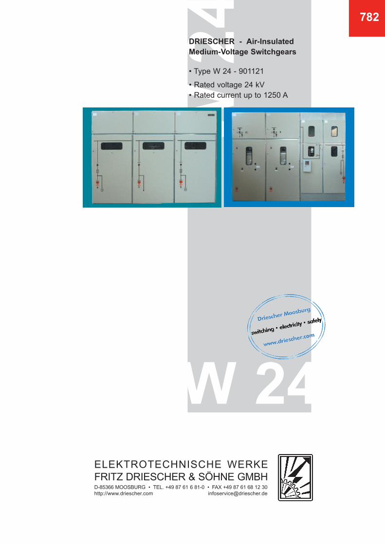
DRIESCHER - Air-Insulated
Medium-Voltage Switchgears
• Type W 24 - 901121
• Rated voltage 24 kV • Rated current up to 1250 A
ELEKTROTECHNISCHE WERKEFRITZ DRIESCHER & SÖHNE GMBHD-85366 MOOSBURG • TEL. +49 87 61 6 81-0 • FAX +49 87 61 68 12 30http://www.driescher.com [email protected]

2
DRIESCHER - 24 kV Switchgears
in compliance with EN 62271-200
• 3 General, Operating conditions, Technical standards, Technical data
• 4 Description of the switch panels
• 5 Overview of the switch panel variants W 24 - 901121
• 6 Switch panel variants W 24 - 901121
• 10 Switch panel variants WL 24 - 901121
• 11 Relay boxes, Insulating protective barriers, Auxiliary equipment, Weights
• 12 Production program
782

3
782
The metal-enclosed, air-insulated medium-voltageswitchgears, Type W 24 can be universally applied:
They range from the compact ring cable switchgearsup to complex power distribution switchgears.Tailored to meet the needs of networks of publicutilities and power supply companies in industryand municipal buildings.These medium-voltage switchgears meet the specificrequirements put by the user in full and ensure asatisfactory power distribution.
The switch panels of Type W 24 - 901121 measure
900 mm in width, 1100 mm in depth and 2100 mm
in height.
They are available as individual panels or as a swit-chgear unit, the equipment and panel sequence ofwhich can be selected by the customer.
The switch panels are type-tested in compliance withDIN VDE 0671, Part 200 including Pehla directiveno. 4.
General
The design of the air-insulated switch panels corre-sponds to the specifications of the EN 62271-200.The resistance to accidental arcs of the switch panelshas been determined at 16, 20, 25 and 31.5 kA; 1 s,by and independent testing institute. The installed
switchgear equipment is designed in compliance withEN 62271-1.The degree of protection of the switch panels corre-sponds to IP 3X.
Technical Standards
Rated voltage
Rated lightning impulse withstand voltage
Rated short-time withstand voltage
Ur
Up
Ud
kV
kV
kV
s
Hz
24
125
50
Rated short-circuit duration
Rated frequency
tk
fr
1
50
Technical Data
Rated (operating) current
I r
Rated short-time current
I k
Rated peak current
I p
Panels with switch-disconnector H 27
Panels with switch-disconnector H 22
Panels with circuit breaker V 24
630 A
630 A and 1250 A
up to 1600 A
up to 20 kA
up to 31,5 kA
up to 31,5 kA
up to 50 kA
up to 80 kA
up to 80 kA
Technical data on the installed switchgear equipment are available for
- Switch-disconnector H 22 in list 722- Switch-disconnector H 27 in list 727- Earthing and disconnecting switches in list 731- Circuit breakers in list 747
The switch panels of Type W 24 are installed in clo-sed electrical operating areas which are only to beentered by skilled personnel and appropriatelyinstructed persons.The equipment can be used at an altitude of up to1000 m above sea level.
For installations above an altitude of 1000 m therated insulating level of the switchgear must be cor-rected accordingly. The switch panels are designedfor use under normal operating conditions in compli-ance with the standard EN 62271-1.
Operating Conditions
Technical data for the installed
switchgear equipment

4
782
Description of the Switch Panels
• Flexible, based on the combination possibility withpanel type D 24
• Safe and reliable through the high quality of ourproducts
• Economical based on continuous further development
• Compact dimensions
• Easy handling
• Minimum amount of maintenance
Benefits
Design
The air-insulated medium-voltage switch panels ofType W 24 - 901121 are metal-encapsulated. The switch panel frame is made of a screwed, hot-galvanized composite structure.The front of the switch panels has a single-wing doorof steel plate with the door hinge optionally on theright or left. A window of compound glass is insertedin the door. The cover in front of the bus bar area is either screwedon or designed as a door for the relay box positionedbehind it.Each switch panel has a screwed on rear panel ofgalvanized sheet metal.Connecting cables are conducted into the switchpanels from below and are mounted on cross railswhich can be adjusted in two dimensions.The doors and covers of the switchgear are paintedin structural paint (available in different coloursaccording to the customer's request).
Equipment
The switch panels of Type W 24 are available in thefollowing versions:
• Cable switch panel Type WK 24• Transformer feeder panel Type WT 24• Measuring switch panel Type WM 24• Bus sectionalizer panel Type WÜ 24• Circuit-breaker panel Type WL 24
The switch panels are optionally designed with a busbar compartment which is either open or closed atthe side.Pressure relief can be in upward or downward direc-tion.
Switch panels equipped with switch-disconnectorscan optionally be fitted with an earthing switch.In circuit-breaker panel, Type WL 24, there is alsoan integrated bus disconnector in addition to thecircuit breaker. It is also possible to equip these panels with a set ofcurrent and voltage transformers as well as with anearthing switch.
The relay boxes extend over the entire width of theswitch panels. These measure 265 mm in depth andare available in 3 different heights (455, 635 and 815mm, see Page 11).
The optional interlocking features of the devicespractically rule out any incorrect operation.All installed switchgear equipment can be operatedmanually or via motor-operated mechanism with clo-sed panel door.
Special measuring panels equipped with current andvoltage transformers complete the program.
Earthing switches or spherical fixed points are avai-lable for earthing and short-circuiting.An insulating protective barrier can be inserted whenthe panel door is closed.It is possible to install corresponding surge voltageprotectors in the panel, if required.
All switch panels are designed with central lockingand double-bit key. There are additional locking features available usingprofile cylinders or padlocks, if required.
Variability Reliability
Customer-oriented
Fle
xib
ility
Adv
ance
d de
velo
pmen
t
Eco
no
mic
al

5
782
Cable
panel
(WK
) F
ig.
Bild
2,3
Measu
ring p
anel
(WM
)F
ig.
7,8
,9,1
0
Air
-In
su
late
d M
ed
ium
-Vo
ltag
e S
wit
ch
Pan
els
24 k
V
Typ
e W
24 -
901121
Bus
sect
ionaliz
er
pa
nel
(WÜ
)F
ig.
4
Tra
nsf
orm
er
fee
de
rp
an
el(
WT
)F
ig.
11,1
2,1
3
Circu
it-bre
ake
r bus
sect
ionaliz
er
panel
(WÜ
L)
Fig
. 15,1
6
Circ
uit-
brea
ker
pane
l(W
L)
Fig
.14,1
7
Bus
sect
ionaliz
er
/Measu
ring p
anel
(WÜ
M) F
ig.5
,6
H 2
2 E
A/E
KH
22 S
EA
H 2
2 E
K/E
A/S
EA
H 2
7 E
K/E
A/S
EA
V24 F
/KU
FV
24 F
/KU
F--
-
---
--
= o
ptio
nal
= n
ot
poss
ible
not
poss
ible
with
curr
ent
or
volta
ge t
ransf
orm
ers
not
poss
ible
with
sw
itch-d
isco
nnect
or
H 2
2 S
EA
*
**
***
*
Sw
itch
Pan
el
Typ
e
W 2
4 -
901121
Dis
connect
ing s
witc
h
Sw
itch-d
isco
nnect
or
/C
ircu
it bre
ake
r
Eart
hin
g s
witc
h
Curr
ent
transf
orm
er
Volta
ge t
ransf
orm
er
782
6
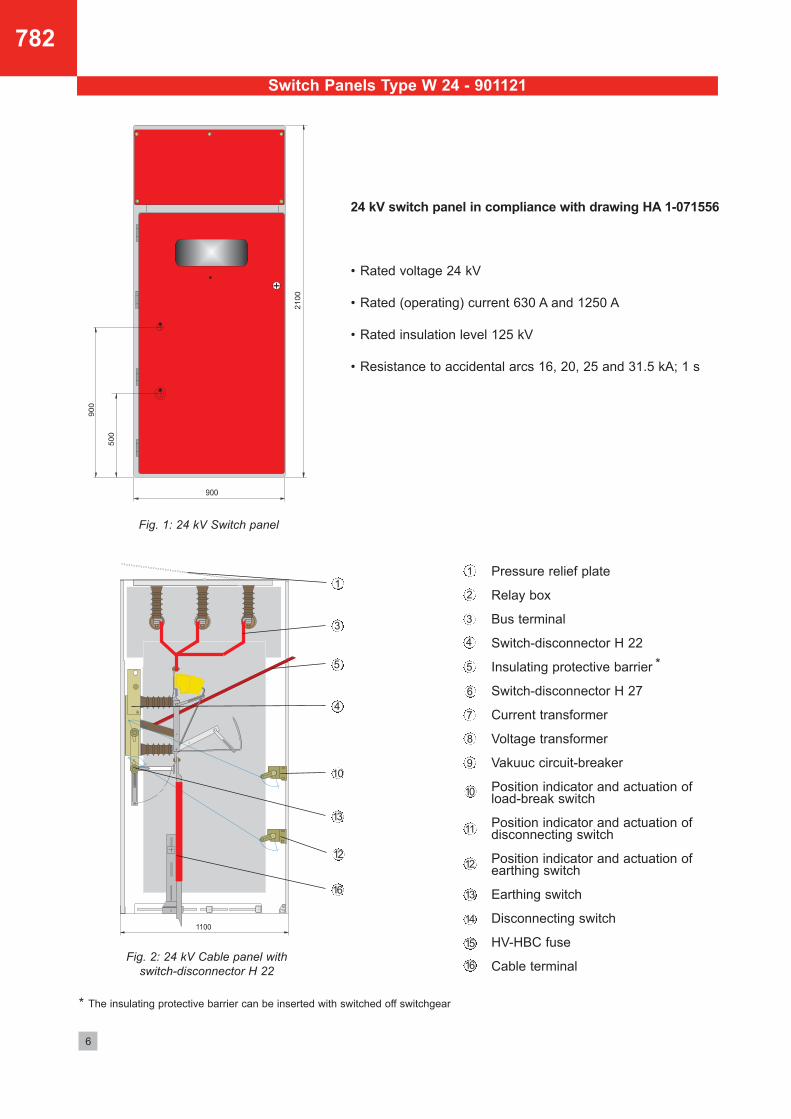
Fig. 2: 24 kV Cable panel with
switch-disconnector H 22
1
3
4
5
Pressure relief plate
Relay box
Bus terminal
Switch-disconnector H 22
Insulating protective barrier
Switch-disconnector H 27
Current transformer
Voltage transformer
Vakuuc circuit-breaker
Position indicator and actuation of load-break switch
Position indicator and actuation of disconnecting switch
Position indicator and actuation ofearthing switch
Earthing switch
Disconnecting switch
HV-HBC fuse
Cable terminal
1
2
3
4
5
6
7
8
9
10
11
10
12
13
12
14
13
15
16
16
Switch Panels Type W 24 - 901121
*
*
The insulating protective barrier can be inserted with switched off switchgear
Fig. 1: 24 kV Switch panel
24 kV switch panel in compliance with drawing HA 1-071556
• Rated voltage 24 kV
• Rated (operating) current 630 A and 1250 A
• Rated insulation level 125 kV
• Resistance to accidental arcs 16, 20, 25 and 31.5 kA; 1 s

782
7
Fig. 3: 24 kV Cable panel with disconnecting
switch and switch-disconnector H 22
1
5
4
3
10
11
13
12
14
16
Fig. 6: 24 kV Bus sectionalizer/Measuring panel
with switch-disconnector H 27 EK/EA
(also possible without switch-disconnector)
3
3
7
7
8
8
6
6
Fig. 4: 24 kV Bus sectionalizer panel with
fuse switch-disconnector H 22 SEA
1
3
4
5
14
11
13
13
10
13
15
Fig. 5: 24 kV Bus sectionalizer/Measuring
panel with fuse switch-disconnector H 27 SEA * *
* The switchgear device H 27 can also be installed on the right
Switch Panels Type W 24 - 901121

8
782
Switch Panels Type W 24 - 901121
Fig. 9: 24 kV Measuring panel with
earthing switch at the bottom
7
8
13
13
12
1 1
33
7
8
1
88
1
3
7
3
7
Fig. 8: 24 kV Measuring panel with cable terminalFig. 7: 24 kV Measuring panel
Fig. 10: 24 kV Measuring panel with
earthing switch at the top

9
782
Fig. 11: 24 kV Transformer feeder panel with
switch-disconnector H 22 SEA
Fig. 12: 24 kV Transformer feeder panel with
switch-disconnector H 27 SuT
Fig. 13: 24 kV Transformer feeder panel with switch-disconnector H22 SEA as well as current and voltage transformer
1
3
4
5
12
11
1
3
5
6
10
10
12
1313
14
15
16
15
1
3
7
8
5
4
12
12
10
16
16
Switch Panels Type W 24 - 901121

782
10
Fig. 14: Circuit-breaker panel in mobile
stationary-mounted design
Fig. 16:
Circuit-breaker bus sectionalizer panel in mobile stationary-mounted design
Fig. 15: Circuit-breaker bus sectionalizer panel
in mobile stationary-mounted design
14
Switch Panels Type WL 24 - 901121
13
12
5
9
9
2
1
3
14
11
11
5
7
8
2
1
3
Auxiliary truck

11
782
Relay Boxes Type W 24 - 901121
Fig. 17: Circuit-breaker panels with 3 variations of relay boxes
Auxiliary Equipment
Weights
Type Designation
WK 24-901121-22WT 24-901121-22WÜ 24-901121-22WM 24-901121WÜM 24-901121-27WL 24-901121-V 24WÜL 24-901121-V 24
Cable panelTransformer feeder panelBus sectionalizer panel
Measuring panelBus sectionalizer / Measuring panel
Circuit-breaker panelCircuit-breaker bus sectionalizer panel
Weight approx. kg
245275300240290350330
Drawing-no.
HA 1 - 071556HA 1 - 071556HA 1 - 071556HA 1 - 071556HA 1 - 071556HA 1 - 071556HA 1 - 071556
The insulated protective barrier is to prevent imper-missible approach to live parts and unintentionalcontact with such parts. This barrier is to be inserted
with closed panel door when work is to be carried outon the switch panel and the system cannot be swit-ched completely dead.
Insulating protective barrier
For assembly, commissioning and maintenance always proceed as specified in the
appropriate instructions.
• Insulating protective barrier in compliance with DIN VDE 0682 Part 552
• Panel illumination• Capacitive voltage testing system in compliance
with (E) DIN VDE 0682 Part 415
• Addtional locking systems with profile cylinder and lockable operating mechanisms
• Short-circuit indicator• Floor coverings

24 k
V
MF
T
W 24
31,5 kA
Order No. 3-81707821 • 02-07
Our range of products includes:
Medium-voltage systems• Single-bus and duplicate-bus switchgear
• Non-withdrawable, withdrawable, and truck-type units
• Compact switchgear assemblies
• Custom-made models
• Industrial systems
Medium-voltage switchgear• Indoor switches, disconnectors, and earthing switches (single and triple pole)
• Indoor circuit breakers (vacuum)
• Outdoor switches (low oil content and vacuum)
• High-voltage high-breaking-capacity fuses
Low-voltage systems• Open-framework design
• Enclosed break devices (up to 6.300 A)
• Cable and fixed-station distribution cabinets
Low-voltage switchgear• Switch disconnectors
• Switch and fuse blocks
• Low-voltage high-breaking-capacity fuses
Driving gear• Hand-operated and motor-operated mechanisms
• Indoor and outdoor driving gear
Accessories• For medium and low voltages
• For station equipment
• Insulators (0.5 kV - 38.5 kV)
• Plastic and glass-reinforced plastic screening
Dimensions, weights , diagrams and descriptions in the list are non-binding. Subject to change without notice.
switching • electricity • safely
ELEKTROTECHNISCHE WERKEFRITZ DRIESCHER & SÖHNE GMBHD-85366 MOOSBURG • TEL. +49 87 61 6 81-0 • FAX +49 87 61 68 12 30http://www.driescher.com [email protected]