metal enclosed switchgears metal clad switchgears gas ... · metal enclosed switchgears metal clad...
TRANSCRIPT

Catalogue 2011
a Friem & Aktif Group Company
Metal Enclosed SwitchgearsMetal Clad SwitchgearsGas Insulated RMU's

Identifies the product as top quality, safe and one step forward of the similar ones.
Symbolizes measurable energy saving products helps to energy continuity.
Identifies smart control logic.
Identifies easy to use products, simplifies the difficult tasks.
Green products, respects to the nature and our future.
Aktif trade mark for Medium voltage switchgears, Switching equipment and Kiosks with high quality and environmentally sensitive
Aktif trade mark for Capacitor Banks, Harmonic Filters, Resistors, Medical Insulated Power Panels, Synchronization and Energy automation Panels with high quality and environmentally sensitive
Aktif trade mark for Measuring, Protection, Automatic Meter Reading, Billing and Energy Management Software.
Aktif trade mark for Measuring, Protection, Control and Power Quality products with high quality, long life and environmentally sensitive

METAL CLAD SWITCHGEARS
AUXILIARY EQUIPMENT
1
B 1 Compartments 15B 2 Application Areas 16B 3 Advantages 16B 4 Standards Complied 16B 5 Technical Specifications 17B 6 Switchgears Types 18
METAL ENCLOSED SWITCHGEARS
C 1 Metal Clad Switchgears 38 C 1.1 Compartments 39 C 1.2 Application Areas 41 C 1.3 Advantages 41 C 1.4 Standards Complied 41 C 1.5 Technical Specifications 42 C 1.6 Switchgears Types 43 C 2 Metal Clad Switchgears for Double Busbar applications 52 C 2.1 Compartments 52 C 2.2 Application Areas 53 C 2.3 Advantages 53 C 2.4 Standards Complied 54 C 2.5 Technical Specifications 54 C 2.6 Switchgears Types 55
TECHNICAL SPECIFICATIONSA 1 Partition Specification 8A 2 Internal Arc Classification (IAC) 8A 3 Loss of Service Continuity (LSC) 9A 4 Insulation of Switchgears 9A 5 Comparison Table 10A 6 Related Standards 10
GAS INSULATED RMUsD 1 Compartments 63D 2 Application Areas 63D 3 Advantages 64D 4 Standards Complied 64D 5 Technical Specifications 65 D 6 Switchgears Types 67D 7 Sample Busbar Designs with RMU Units 78
E 1 Switching Equipment 82 E 2 Protection Devices 86E 3 Measuring Devices 89E 4 Measuring Transformers 93

2
Aktif Raylı Sistemler Ltd.
Aktif Railway Systems (ARS) is established in 2008 for the designing and providing of traction systems' substations as well as providing on-board equipment used on vehicles.
The main purpose of ARS is providing engineering services and products to public bodies and companies in this sector. Even though it is a brand new company, ARS managed to complete successfully both Antalya Light Rail System project as well as Istanbul Metro Stinger System projects.
Aksis Enerji Sistemleri Ltd.
Aksis Energy Metering Systems (AKS) is established in 2003 for providing metering solutions like Automatic Meter Reading, Billing Software in every level of energy sector. The company is focused on saving and efficient using of energy by its Meter Management and Loss & Leakage tracing solutions. AKS answers all expectations in power systems with high quality products and custom design software solutions. AKS customers create over 100 million Euro energy bills using different Metering, Management and Billing methods of AKS.
Aktif Mühendislik Ltd.
Aktif Engineering (AMDT) is established in 1996 Measuring, Protecting and Quality of Electricity. 2200m2 headquarter of AMDT is located in Istanbul consisting of 35 employees. Since establishment AMDT provides high quality engineering, supplying and start-up services for the power quality, energy saving, energy metering, protection. AMDT provides standard and custom designed solutions to domestic and international customers, with over 15 years of experience.
Company Profile

3
Coet S.r.L.
Since establishment in 1962 in Milan, COET has been producing AC/DC switching equipments and panels that are used safely by its customers thanks to the COET's work on industrial and electric equipment and patents obtained in this field. All manufactured products are the result of long technical research and development work. This way, the company is known for the originality and diversity of its planned solutions. COET has been working on Industrial and railway systems and has become one of the leading companies in the field of supplying switching equipments for traction substation.
Aktif Elektroteknik A.Ş.
The company is established to manufacture Switchgears and Kiosks under the name of “Setas” in 1981. First in 2008, company merged to Aktif Group as Aktif Elektroteknik (AET) and then the company becomes international after significant participation of Italian Friem S.p.A in 2009. 9000m2 factory of AET is located in Ankara consisting of over 100 employees. AET operates with its 30 years of manufacturing experience, modernized machinery line, ever increasing know-how, experienced Turkish and Italian R&D teams, quality products type tested by the leading accredited European laboratories and the vision of new ideas to meet with future expectations.
Company Profile
Friem S.p.A.
Friem manufactured over 40 million ampere and 1000 power rectifiers for the worldwide since it's established in Milan at 1950.
Having technical knowledge of energy and electro mechanics along with ability of complete design of conversion systems, FRIEM provides also high voltage DC insulators, DC switches, anodic control and protection products and auxiliary equipments like polarization products to its customers. Friem is a share holder of Aktif Elektronik in Turkey and also COET S.r.L in Italy.

4
Introduction
Aktif Group is in continuous development with its customer oriented activities, advanced engineering know-how, R&D works, software developing abilities and with the continuous support of loyal customers that are attained and protected by precise work and ethical principles of the company.
The group companies have ISO 9001 since 90s and our factory has ISO 14001 Environment and ISO 18001 Occupational Health and Safety Certificates.
Technology
The most important activities of Aktif is R&D and increase the Employee quality which the investment amount of these activities are more than average.
All mechanical projects are designed by 3D-CAD platforms. Power flow, test and quality works are calculated by Worldwide accepted simulation software and ActWin software as well as developing software for different platforms.
In order to increase the production quality and capacity all machinery within the facility are renewed with latest technology equipment in 2009.
Vision
To increase the number of our loyal customers in global market, hence increasing the market share and becoming reputable, reliable and preferred company as worldwide with our;
prominent quality difference,customer oriented approach,innovative activities,open minded approach.
Mission
By the help of our following missions are continuing to announce product quality and knowledge of our company and country in best possible way by meeting rising customer expectations.
� open minded approach� high quality policy � innovative ideas� constantly improved processes� polished employees� knowledge based decisions
Company Profile

5
High Performance, Durable and Simple
Endurance of our products, which are produced with high level of awareness and accurateness in addition to follow international standards, ensures an outstanding performance for the users. Therefore our products are considered as top of the line products.
Visual simplicity and being user friendly are the design criteria for the software and hardware of our products. Our products have the most simple and functional features for emergency applications as well as persistence of habits and customer satisfaction are basics in design, production and shipment.
Security
The human safety and security are the main concerns in all of our products.
Design, Interlock logics and documentation of our products are implemented, manufactured and tested in order to reach the highest safety level.
Furthermore, services and site works are done according to human safety rules by taking into account the dangerous of electricity.
Service Continuity
The service continuity means efficiency of power consequently profitability of the business.
Our products are designed and manufactured in order to ensure energy sustainability and provide the best service availability.
This policy is the cornerstone of our orientation and training programs and it is fully applied by our technical and administrative staff.
Local & Remote Monitoring
Energy continuity and efficiency can be ensured only by monitoring of equipments local and remotely.
Our products are designed with remote monitoring and management features by the help of our software development abilities on different platforms and hardware capabilities. This will ensure the saving and profitability, directly.
Company Profile

A 1 Partition Specification A 1.1 Accessible Compartments A 1.2 Non-accessible Compartments A 1.3 Partition ClassA 2 Internal Arc Classification (IAC)A 3 Loss of Service Continuity (LSC)A 4 Insulation of SwitchgearsA 5 Comparison TableA 6 Related Standards
6
888899
101011

TechnicalInformation

Metal Enclosed switching and control equipment between the rated voltage 1 - 52 kVac are defined in IEC 62271-200 standards.
It is possible to classify the Switchgears in accordance with the specifications given in IEC 62271-200 standard conveniently in the below given table.
A 1 Partition Specifications
The structure of the switchgears partitions and their features are provided in 3 main headings as seen in the attached table.
A 1.1 Accessible Compartments
� Interlock-controlled accessible compartment: Compartment containing high voltage parts, intended to be opened for normal operation and/or normal maintenance as stated by the manufacturer, in which Access is controlled by integral design of the switchgear and controlgear. Installation, extension, repairing are not considered as normal maintenance
� Procedure-based accessible compartments: Compartments containing high-voltage parts, intended to be opened for normal operation and/or normal maintenance as stated by the manufacturer, in which Access is controlled by suitable procedure combined with locking. Installation, extension, repairing are not considered as normal maintenance
� Tool based accessible compartments: Compartment containing high-voltage parts, that may be opened, but not for normal operation and maintenance. Special procedures are required. Tools are necessary for opening.
A 1.2 Non-accessible Compartments
Compartments that should not be needed to open and the opening may damage the integrity which contains high-voltage.
A 1.3 Partition Class
It is a classification that defines whether metallic or non-metallic parts to be used or not for the purpose of segregating the compartments contains live parts.
Partition class PM Switchgear providing continuous metallic partitions and/or shutters, intended to be earthed, between opened accessible compartments and live parts of the main circuits
Partition class PI Switchgear having one or more non- metallic partitions or shutters between opened accessible compartments and live parts of the main circuit
Technical InformationA
8
a Friem & Aktif Group Company
MediumVoltage
Switchgears
PartitionSpecifications
InternalArcClassification
Loss ofServiceContinuity
Insulation ofCompartments
AccessibleCompartments
Non-accessibleCompartments
PartitionClass
Switchgears classification according to IEC 62271-200

A 2 Internal Arc Classification
It is a classification for metal enclosed switchgear and controlgear, to ensure that in case of an internal arc the defined conditions for protecting people are met and verified by the appropriate test.
Three types of accessibility are defined, by considering possible accessibility of Switchgears at site.
Accessibility Type A: Restricted to the authorized personal only
Accessibility Type B: Unrestricted accessibility, open to any people
Accessibility Type C: Accessibility restricted by installation which is out of reachable distance for pole mounted switchgears. The allowable minimum height of the facility should be defined by the manufacturer.
The metal enclosed switchgear and controlgear may have different accessibilities for different directions. The following codes should be used to define accessibility from different directions.
F : Front L : Side R : Back
A 3 Loss of Service Continuity
It is a classification which defines the keeping of other Switchgears and/or functional units in energizing position when main circuit compartment of a switchgear is opened.
LSC2: It shows the having to other accessible compartments out of the main busbar compartment of single busbar switchgear and controlgear. Two subsections are defined.
LSC2B: defines the Switchgears that opening and interfering of switching compartment is allowed while both cable and busbar compartment is energized.
LSC2A: defines the Switchgears that opening and interfering of switching compartment is allowed while only busbar compartment is energized.
LSC1: defines the Switchgears that opening and interfering of switching compartment is not possible while any of busbar or cable compartments is energized since cable and current-voltage transformers are located in a single section.
a Friem & Aktif Group Company
9
Technical Information A

10
A 5 Comparison Table
A 4 Insulation of Switchgear
Switchgears may have different types of insulations as follows:
� Air Insulated� Gas Insulated� Liquid Insulated
a Friem & Aktif Group Company
LSCIACIPUrIrIk
2B-PMAFLR
40Up to 40.5 kVUp to 4000 AUp to 50 kA
2A-PIAFL40
Up to 40.5 kVUp to 1250 AUp to 25 kA
Specifications
PMAFL67
Up to 40.5 kVUp to 1250 AUp to 25 kA
Metal CladSwitchgears
Metal EnclosedSwitchgears RMU Units
Technical InformationA
SMC series Metal Clad Switchgears
SME series Metal Enclosed Switchgears

a Friem & Aktif Group Company
A 6 Related Standards
The IEC 60298 was able to meet the standards while it was utilized in previous years. However, due to the advancement of the technology and developments in Switchgears designs, and bringing the safety to the forefront, the standard was no able to handle the power cuts of the systems as well as maintenance needs of the users.
In the following table the new IEC 62271 standard and its sections and corresponding old standard numbers are written as it's published by SC17A and SC17C committees.
Common specifications for high-voltage switchgear and controlgear standards
Seismic Competence for rated voltage of 72.5 kV and above
High-voltage alternating current circuit-breakersSynthetic testing of high voltage alternating current circuit breakersAlternating current disconnectors and earthing switchesSwitches for rated voltages above 1 kV and less than 52 kVHigh voltage switches for rated voltages of 52 kV and aboveAlternating current switch-fuse combinationsHigh voltage alternating current contactors and contactor-based motor-startersHigh voltage alternating current switchgear-fuse combinationsSwitchgear having combined functionsAlternating-current series capacitor by-pass switchesAC metal enclosed switchgear and controlgear for rated voltages above1 kV and up to an including 52 kVAC insulation-enclosed switchgear and controlgear for rated voltages above1 kV and up to an including 38 kVHigh-voltage/low-voltage prefabricated substationsGas-insulated metal enclosed switchgear for rated voltages of 72.5 kV and aboveRigid high-voltage, gas-insulated transmission lines for rated voltages of72.5 kV and aboveGuide for seismic qualification of high-voltage alternating current circuit breakersHigh-voltage alternating current circuit breakers - Inductive load switchingHigh-voltage alternating current circuit breakers - Guide for short circuit andswitching test procedures for metal-enclosed and dead tank circuit breakersHigh-voltage switchgear and controlgear - Use and handling of SF6 in high voltageswitchgear and controlgearAdditional requirements for enclosed switchgear and controlgear from1 kV to 72.5 kV to be used in severe climatic conditionsCable connections for gas-insulated metal-enclosed switchgear forrated voltages of 72.5 kV and above - Fluid filled and extruded insulation cables- Fluid-filled and dry type cable terminatorsDirect connection between power transformers and gas-insulatedmetal-enclosed switchgear for rated voltages of 72.5 kV and above.High-voltage switchgear and controlgear - The use of electronic andassociated technologies in auxiliary equipment of switchgear and controlgearGuide for asymmetrical short-circuit breaking test duty T100aTRV parameters for high voltage switchgear and controlgear with rated value ove 1 kV and under 100 kVElectric endurance test for circuit breakers with rated voltage of 72.5 kV and above
IEC 60694-
IEC 60056IEC 60427IEC 60129IEC 60265-1IEC 60265-2IEC 60420IEC 60470---IEC 60298
IEC 60466
IEC 61330
IEC 60517IEC 61640
IEC 61666IEC 61233IEC 61633
IEC 61634
IEC 61932
IEC 60859
IEC 61639
IEC 62063
-
-
-
1
2
100101102103104105106107108109200
201
202
203204
300301302
303
304
305
306
307
308309
310
IEC 62271 HIGH VOLTAGE SWITCHGEAR AND CONTROLGEAR
Old IEC NumberSection New Heading
11
Technical Information A

B 1 Compartments B 2 Application Areas B 3 Advantages B 4 Standards Complied B 5 Technical Specifications B 6 Switchgears Types B 6.1 Incoming Switchgears with Disconnectors B 6.2 Incoming Switchgears with Load Break Switch B 6.3 Cable Connection Switchgears B 6.4 Incoming Switchgears with Circuit Breaker B 6.5 Outgoing Switchgears with Circuit Breaker B 6.6 Outgoing Switchgears with Vacuum Contactor B 6.7 Outgoing Switchgear with Fuse and Load Break Switch B 6.8 Bus Coupling Switchgears B 6.9 Bus Coupling Switchgears with Load Break Switch B 6.10 Bus Section with Load Break Switch B 6.11 Bus Section with Circuit Breaker B 6.12 Bus Riser B 6.13 Bus Voltage Measuring Switchgear B 6.14 Bus Current Measuring Switchgear B 6.15 Current & Voltage Measuring Switchgear with Load Break Switch B 6.16 Surge Arrestor Switchgears
12
15161616171820212223242526272829303132333435

Metal EnclosedSwitchgears

14
SME series Metal Enclosed Switchgears are the switching and control equipment between 1 kV and 40.5 kV, manufactured in conformity with IEC 62271-200.
The first Metal Enclosed Switchgear of Turkey is manufactured in Aktif factory in 1995 and tested in international test laboratories.
SME series Metal Enclosed Switchgears are manufactured by galvanized metal sheet with 2 mm thickness and painted by electro-static powder paint in colors conforming to RAL coding.
SME series Metal Enclosed Modular Switchgears manufactured by Aktif Elektroteknik are defined with following features as per IEC 62271-200 standards:
� Air insulated� LSC 2A Loss of Service continuity� PI Partition Class � AFL Internal Arc Classification� 3 accessible compartments
a Friem & Aktif Group Company
B SME series Metal Enclosed Switchgears

15
a
a
b
c
B 1 Compartments
SME series Metal Enclosed Switchgears contain3 segregated compartments.
a - Low Voltage Compartmentb - Busbar Compartmentc - Switching Equipment Compartment
a - Low Voltage Compartment
This compartment contains all secondary circuits for measurement, protection, control, monitoring, communication and other associated systems.
b - Busbar Compartment
Busbar Compartment mainly consists of;- Electrolytic copper busbars according to rated current.- Epoxy resin post insulatorsAccess to busbar compartment is possible with special safety procedures and tools.
c - Switching Equipment Compartment
In this Compartment following equipment is contained according to the project specifications:
� Switching equipment� Current transformers� Voltage transformers� Surge arresters� Grounding � Capacitive voltage divider� Cable connection couplings
Furthermore, this compartment also contains following switching equipment:
� SF6 Gas or vacuum circuit breaker� SF6 Gas insulated Load Break Switch� SF6 Gas insulated or Rotary Disconnector� Vacuum Contactor
Switching compartment access is controlled by integral design of Metal Enclosed Switchgear to ensure safe operation according to IEC 62271-200
The following mechanic Interlocks are provided as standard:
performing of Load Break switches with/without fuses is not possible when; the Switching compartment door is open and/or, the Grounding disconnector is in Closed position
switching of Disconnectors used together with circuit breakers is not possible when; the Switching compartment door is open , the Circuit Breaker is Closed position and/or, the Grounding disconnector is in Closed position
switching of Grounding disconnector is not possible when; the Line Disconnector is in Closed position.
a Friem & Aktif Group Company
BSME series Metal Enclosed Switchgears
c

16
B 2 Application Areas
Metal Enclosed Switchgears are especially used in the transformer centers, distribution systems, renewable energy production and industrial plants where the rated current up to 1250 A and short circuit current up to 25 kA.
� Energy Distribution Centers� Hydroelectric and Wind Energy Applications� Diesel and Natural Gas Power Plants� Transformer Substations� Cement Factories� Auto Industry� Petroleum and Chemical Industry� Iron and Steel Industry� Rolling Mills� Pipe lines� Shipyards� Emergency Situation and Stand-by Power Facilities� Ore Mines� Railway Substations
B 3 Advantages
� LSC2A service continuity � Grounded metal separation between compartments� Maximum human safety with AFL internal arc testing feature � Safe electrical and mechanical Interlock systems do not allow to operational faults� SF6 gas insulated Circuit breaker allows fast and easy servicing� Grounding system with ensured continuity � Modular design, which allows extension easily� Tested short time withstand current up to 25 kA / 1 s.� Interactive mimic diagram � Proven reliability with unique design� Low maintenance cost� Easy and safety operation with inverlock� After sale service and spare parts availability
B 4 Standards Complied
SME series Switchgears are manufactured in conforming to following standards:
� IEC 62271-1 : General articles relating to High Voltage Switchgears � IEC 62271-200 : Metal Enclosed Switchgears (1 - 52 kVac)� IEC 62271-100 : Circuit Breakers (1 - 52 kVac)� IEC 62271-102 : Main Circuit and grounding Disconnectors� IEC 62271-105 : AC Switch and Fuse combinations� IEC 60044-1 : Current Transformers� IEC 60044-2 : Voltage Transformers� IEC 60273 : Insulators� IEC 60051 : Measuring Devices� IEC 60255 : Secondary Protection relays
a Friem & Aktif Group Company
B SME series Metal Enclosed Switchgears

17
B 5 Technical Specifications
a Friem & Aktif Group Company
BSME series Metal Enclosed Switchgears
Note: Full type tests of SME series switchgears up to 25 kA are performed at VEIKI accredited laboratories in Hungary.
Technical Spesifications
Descriptions
kV
kV
kV
Hz
AAA
kAkA
kAkAs
kAs
kAkAs
3,6
10
40
7,2
20
60
12
28
75
24
50
125
LSC 2AAFLPI
IP 40IP 20
Rated Voltage (rms)Power frequency withstand voltage 50 Hz, 1 min(rms) between phases and phase-ground
Lightning impulse withstand voltage 1.2/50ms(peak) between phases and phase-groundRated frequency
Rated (rms) current of switchgears with
Rated short time withstand (rms) current with
Rated short time withstand (peak) current with
Short circuit withstand timeInternal Arc Failure
Earthing Disconnector
Switchgear Structure as per the
Protection Class
ColorStandards complied
BusbarsC/B and Disconnector
Load break switches
C/B and DisconnectorsLoad break switches
C/B and DisconnectorsLoad break switches
CurrentDuration
Rated short circuit current making capacityRated short time withstand (peak) current
Rated short circuit withstand time
loss of service continuityinternal arc classification
partition class
when doors are closed between compartments
SME 3,6 SME 7,2
17,5
38
95
SME 17,5SME 12 SME 24
36
70
170
SME 36
40,5
85
185
SME 40,5
630 ... 1250630 ... 1250
630
16 - 20 - 2516 - 20
40 - 50 - 6340 - 50
1
16 - 20 - 251
16 - 20 - 2540 - 50 - 63
1
630 ... 1250630 ... 1250
630
16 - 20 - 2516 - 20
40 - 50 - 6340 - 50
1
16 - 20 - 251
16 - 20 - 2540 - 50 - 63
1
16 - 20 - 2540 - 50 - 63
1
630 ... 1250630 ... 1250
630
16 - 20 - 2516 - 20
40 - 50 - 6340 - 50
1
16 - 20 - 251
IEC 62271-200
50 - 60
RAL 9003 / 7035

18
B 6 Switchgears Types
� Incoming Switchgear with Disconnector
Is the switchgear without protection and on load switching features, with the rated current up to 1250 A and short circuit level up to 25 kA.
� Incoming Switchgear with Load Break Switch
Is the switchgear which allows the switching on load but without protection features with the rated current up to 630 A and short circuit level up to 20 kA.
� Cable Connection Switchgear
Is the switchgear to connect the distribution busbar with the cables connected from the bottom without using any switching and protection features with the rated current up to 1250 A and short circuit level up to 25 kA.
� Incoming/Outgoing Switchgear with Circuit Breaker
Is the switchgear for the incoming of distribution busbar with rated current up to 1250 A and short circuit current up to 25 kA which allows the protection and switching operation during short circuit.
� Outgoing Switchgear with Vacuum Contactor
Is the switchgears used where frequent switching operation is required with rated voltage up to 24 kV and rated current up to 400 A.
� Outgoing Switchgear with Load Break Switch and Fuse
Is the switchgear which allows the switching on load and contains short circuit fuses for protection features with the rated current up to 630 A and short circuit level up to 20 kA.
� Bus Coupling Switchgear
Switchgear to connect the different busbars whether feed by the same or different supply with rated current up to 1250 A and short circuit current up to 25 kA. This switchgear is a combination of Bus section and Bus riser switchgears.
� Bus Coupling Switchgear with Load Break Switch
Switchgear where the connection of two different busbars are realized manually without protection and paralleling features whether feed by the same or different supply with rated current up to 630 A and short circuit current up to 20 kA.
a Friem & Aktif Group Company
Incoming withDisconnector
Incoming withLoad Break Switch
Cable connection
Bus Coupling
Incoming/Outgoingwith Circuit Breaker
Outgoing withLoad Break
Switch and fuses
B SME series Metal Enclosed Switchgears
Bus Coupling withLoad Break Switch

19
� Bus Section Switchgear with Load Break Switch
Switchgear where the connection of two different busbars are realized manually without protection and paralleling features whether feed by the same or different supply with rated current up to 630 A and short circuit current up to 20 kA.
� Bus Section Switchgear with Circuit Breaker
Switchgear where the connection of two different busbars are realized automatically with protection and paralleling features whether feed by the same or different supply with rated current up to 1250 A and short circuit current up to 25 kA.
� Bus Rising Switchgear
Switchgear Is used for the connection of Bus section switchgear' busbars by rising up to other busbar system with rated current up to 1250 A and short circuit current up to 25 kA.
� Bus Voltage Measuring Switchgear
Switchgear is used for obtaining voltage information for the measurement and protection purposes in the metal enclosed busbar with rated current up to 1250 A and short circuit current up to 25 kA with the help of Secondary protection relays and measurement devices like Voltmeter, Power Analyzers, Electricity meters, etc ...
� Bus Current Measurement Switchgears
Switchgear with rated current up to 1250 A and short circuit current up to 25 kA in where the current information of the distribution busbars is obtained for the using of Secondary protection relays and measurement devices such as Ammeter, Analyzers and Electricity Meters.
� Current & Voltage Measuring Switchgears
Switchgear with rated current up to 630 A and short circuit current up to 20 kA in which the current and voltage information of the distribution busbars is obtained to use at Secondary protection relays and measurement devices such as Ammeter, Voltmeter, Analyzers and Electricity Meters.
� Surge Arrester Switchgear
It is used on the busbars rated current up to 1250 A and short circuit current up to 25 kA, to protect the system and apparatus against temporary over voltages caused by the lightning surges and switching surges.
a Friem & Aktif Group Company
Bus VoltageMeasuring
Voltage & CurrentMeasuring with LBS
Current Measuring
Bus Riser
Surge ArrestorSwitchgears
Bus Section withLBS / Disconnector
Bus Section withCircuit Breaker
BSME series Metal Enclosed Switchgears

B 6.1 Incoming Switchgear with Disconnector
Is the switchgear without protection and on load switching features, with the rated current up to 1250 A and short circuit level up to 25 kA.
In this switchgear 3 poles and 3 positioned (open– close- earthed) SF6 gas insulated disconnector is used as standard and alternatively Rotary Disconnectors may be used.
Incoming switchgears with disconnectors are used on;Incoming of MV distribution busbar which does not stand protection and load switching.
* This product is an option of SF6 gas insulated disconnector.
20
a Friem & Aktif Group Company
Switchgear Dimensions
Rated Voltage (kV)3.6 - 12
17.5 - 2436
40.5
Width (mm)375500750
1000
Height (mm)2000200022502300
Depth (mm)900900
14001500
B SME series Metal Enclosed Switchgears
SF6 Gas Insulated DisconnectorAir Insulated Rotary switch *Thermostat and Heater KitCopper BusbarCapacitive Voltage Indicator SetFault Location indicatorSurge ArrestorCurrent TransformerAmmeterTest TerminalCable Connection TerminalSCADA ConnectionsInterlock
Options
x
xxxx
x
Standardx
xxxx
x
x
Switchgear Equipment

21
a Friem & Aktif Group Company
B 6.2 Incoming Switchgear with Load Break Switch
Is the switchgear which allows the switching on load but without protection features with the rated current up to 630 A and short circuit level up to 20 kA.
In this switchgear 3 poles and 3 positioned (open-close-earthed) SF6 gas insulated Load Break switch is used as standard.
Incoming switchgears with Load Break Switch are used at;- Incoming of MV distribution busbars and- In some applications also at outgoing feeders where there is no need for protection.
Switchgear Dimensions
Rated Voltage (kV)3.6 - 12
17.5 - 2436
Width (mm)375500750
Height (mm)200020002250
Depth (mm)900900
1400
BSME series Metal Enclosed Switchgears
SF6 Gas Insulated Load Break SwitchMotor operation mechanismThermostat and Heater KitCopper BusbarCapacitive Voltage Indicator SetFault Location indicatorSurge ArrestorCurrent TransformerAmmeterTest TerminalRemote Operation setCable Connection TerminalSCADA ConnectionsInterlock
Options
x
xxxxx
x
Standardx
xxxx
x
x
Switchgear Equipment

22a Friem & Aktif Group Company
B SME series Metal Enclosed Switchgears
B 6.3 Cable Connection Switchgear
Is the switchgear to connect the distribution busbar with the cables connected from the bottom without using any switching and protection features with the rated current up to 1250 A and short circuit level up to 25 kA.
Busbar connection switchgears are used to supply;- Side connected Incoming switchgears - Outgoing switchgears and- Opposite busbar incoming fed from the outgoing cubicle at opposite arrangement of switchgears.which consist of switching and protection.
Switchgear Dimensions
Rated Voltage (kV)3.6 - 12
17.5 - 2436
Width (mm)375500750
Height (mm)200020002250
Depth (mm)900900
1400
Earthing DisconnectorThermostat and Heater KitCopper BusbarCapacitive Voltage Indicator SetCable Connection TerminalSCADA ConnectionsInterlock
Standard OptionsSwitchgear Equipment
xx
x
x
x
xx

23
a Friem & Aktif Group Company
BSME series Metal Enclosed Switchgears
B 6.4 Incoming and outgoing Switchgear with Circuit Breaker
Is the switchgear for the incoming of distribution busbar with rated current up to 1250 A and short circuit current up to 25 kA which allows the protection and switching operation during short circuit.
Switching is operated by 3 poles SF6 gas insulated Circuit Breaker and Disconnection operation is realized by the using of 3 positioned (open-close-earthed) SF6 gas insulated disconnector as standard or Rotary switch as an option.
Incoming Switchgears with Circuit Breaker are used in;- Network or Generator incoming feeders,- Incoming feeders of Open/Close Ring operated networks.Standard incoming switchgears are used also as outgoing
Switchgear Dimensions
Rated Voltage (kV)3.6 - 1217.5 - 24
3640.5
Width (mm)750750
10001200
Height (mm)2000200022502300
Depth (mm)900900
14001500
* This product is an option of SF6 gas insulated disconnector.
Circuit BreakerSF6 Gas Insulated DisconnectorAir Insulated Rotary Switch *Main Busbar Earthing DisconnectorCopper BusbarCapacitive Voltage Indicator SetThermostat and Heater KitSurge ArrestorVoltage Transformer and MV FuseVoltmeter and Commutator setCurrent TransformerAmmeterPower AnalyzerElectricity MeterOver Current RelayOther secondary protection relays Cable Connection TerminalSCADA ConnectionsGSM-GPRS Modem Converter SetInterlock
Standard OptionsSwitchgear Equipmentxx
xxx
x
x
x
x
x
xx
xx
xxxx
x
x
switchgear for any kind of application.
withVT90090011501350
withVT & fuse1000100012501400

24
a Friem & Aktif Group Company
B SME series Metal Enclosed Switchgears
B 6.5 Outgoing Switchgear with Circuit Breaker
Is the switchgear for the outgoing from distribution busbar with rated current up to 1250 A and short circuit current up to 25 kA which allows for the protection and switching operation during short circuit.
Switching is operated with 3 poles SF6 gas insulated Circuit Breaker and Disconnection operation is realized by the using of 3 positioned (open-close-earthed) SF6 gas insulated disconnector as standard or Rotary switch as an option.
Outgoing Switchgears with Circuit Breaker are mainly used in;- Any load feeders supplied from Distribution Busbars- Line feeders supplied from Distribution Busbars- Outgoing feeders of Open/Close Ring operated networks.Standard outgoing switchgears are used as Incoming switchgears at some site application.
Switchgear Dimensions
Rated Voltage (kV)3.6 - 1217.5 - 24
3640.5
Width (mm)750750
10001200
Height (mm)2000200022502300
Depth (mm)900900
14001500
* This product is an option of SF6 gas insulated disconnector.
Circuit BreakerSF6 Gas Insulated DisconnectorAir Insulated Rotary Switch*Main Busbar Earthing DisconnectorCopper BusbarCapacitive Voltage Indicator SetThermostat and Heater KitSurge ArrestorVoltage TransformerVoltmeter and Commutator setCurrent TransformerAmmeterPower AnalyzerElectricity MeterOver Current RelayOther secondary protection relays Cable Connection TerminalSCADA ConnectionsGSM-GPRS Modem Converter SetInterlock
Standard OptionsSwitchgear Equipmentxx
xxx
x
x
x
x
xx
xxx
xxx
x
xx

B 6.6 Outgoing Switchgear with Vacuum Contactor
Is the switchgears used where frequent switching operation is required with rated voltage up to 24 kV and rated current up to 400 A.
For the switching operation 3 poles vacuum contactor is used and disconnection operation is realized by 3 poles 3 positioned (open-close-earthed) SF6 gas insulated disconnector as standard or air insulated Rotary Switch as an alternative.
Outgoing Switchgear with contactor is used for feeding of;- Capacitor Banks- Harmonic Filters- Shunt Reactors and- Motors
Switchgear Dimensions
Rated Voltage (kV)3.6 - 12
17.5 - 24
Width (mm)750750
Height (mm)20002000
Depth (mm)900900
25
a Friem & Aktif Group Company
BSME series Metal Enclosed Switchgears
Vacuum ContactorSF6 Gas Insulated DisconnectorAir insulated Rotary Switch *Copper BusbarCapacitive Voltage Indicator SetM.V. Protection FusesThermostat and Heater KitSurge arresterCurrent TransformerAmmeterOver Current RelayOther secondary protection relays Test TerminalCable Connection TerminalSCADA ConnectionsGSM-GPRS Modem Converter SetInterlock
Standard OptionsSwitchgear Equipmentxx
xxxx
x
x
x
xxxxxx
xx
* This product is an option of SF6 gas insulated disconnector.

B 6.7 Outgoing Switchgear with Load Break Switch and Fuse
Is the switchgear which allows the switching on load and contains short circuit fuses for protection features with the rated current up to 630 A and short circuit level up to 20 kA.
In this switchgear 3 poles and 3 positioned (open-close-earthed) SF6 gas insulated Load Break switch is used as standard.
Outgoing switchgear with fused type Load Switch is used for;- Feeding of Transformers with rated power up to 400 kVA- Feeding of Transformers with rated power up to 1600 kVAwith the condition of being in the same location with distribution transformer.
Switchgear Dimensions
Rated Voltage (kV)3.6 - 1217.5 - 24
36
Width (mm)375500750
Height (mm)200020002250
Depth (mm)900900
1400
26
a Friem & Aktif Group Company
B SME series Metal Enclosed Switchgears
SF6 Gas Insulated Load Break SwitchMotor operating mechanismCopper BusbarCapacitive Voltage Indicator SetM.V. Protection FusesThermostat and Heater KitRemote Operation setCable Connection TerminalSCADA ConnectionsInterlock
OptionsStandardSwitchgear Equipmentx
xxxxxx
x
x
x

27
a Friem & Aktif Group Company
BSME series Metal Enclosed Switchgears
B 6.8 Bus Coupling Switchgear
Switchgear to connect the different busbars whether feed by the same or different supply with rated current up to 1250 A and short circuit current up to 25 kA. This switchgear is a combination of Bus section and Bus riser switchgears. Inside the switchgear 3 poles SF6 gas insulated Circuit Breaker and 2 pieces of 3 positioned (open-close-earthed) SF6 gas insulated Disconnectors are used as standard.
Bus Coupling Switchgears are used to;- Connect two different busbars and- Synchronizing of Power plants or Renewable Energy supplies to the network.
x
* This product is an option of SF6 gas insulated disconnector.
Switchgear Dimensions
Rated Voltage (kV)3.6 - 12
17.5 - 2436
40.5
Width (mm) 1125 * 1250 * 1750 *
2200
Height (mm)2000200022502300
Depth (mm)900900
14001500
* This product is an option of SF6 gas insulated disconnector.
Circuit BreakerSF6 Gas Insulated DisconnectorsAir Insulated Rotary Switches *Thermostat and Heater KitCopper BusbarVoltage TransformerVoltmeter and Commutator setCurrent TransformerAmmeterPower AnalyzerElectricity MeterOver Current RelayOther secondary protection relaysCable Connection TerminalSCADA ConnectionsGSM-GPRS Modem Converter SetInterlock
OptionsSwitchgear Equipment Standardxx
xx
x
x
x
x
x
xx
xxx
x
xx

28
a Friem & Aktif Group Company
B SME series Metal Enclosed Switchgears
B 6.9 Bus Coupling Switchgear with Load Break Switch
Switchgear where the connection of two different busbars are realized manually without protection and paralleling features whether feed by the same or different supply with rated current up to 630 A and short circuit current up to 20 kA.
In this switchgear SF6 gas insulated Load Break switch with 3 poles and 3 positions (open-close-earthed) is used as standard. Instead of LBS, SF6 gas insulated disconnector or Rotary switch can be used optionally also to increase the rated current to 1250A, and short circuit current to 25 kA.
Bus Coupling Switchgear with Load Break switch is used to connect two busbars each other manually or automatically without protection.
Switchgear Dimensions
Rated Voltage (kV)3.6 - 12
17.5 - 2436
Width (mm)750
10001150
Height (mm)200020002250
Depth (mm)900900
1400
SF6 Gas Insulated Load Break SwitchSF6 Gas Insulated Disconnector *Air Insulated Rotary Switch *Motor set for spring chargingThermostat and Heater KitCopper BusbarCapacitive Voltage Indicator SetVoltage TransformerVoltmeter and Commutator setCurrent TransformerAmmeterPower AnalyzerElectricity MeterMotor set for Remote Open-CloseSCADA ConnectionsInterlock
Standard OptionsSwitchgear Equipment
* These products are the option of SF6 gas insulated Load Break switch when there is no need to switching on-load.
x
xxx
x
xxx
xxxxxxxx

29a Friem & Aktif Group Company
BSME series Metal Enclosed Switchgears
B 6.10 Bus Section Switchgear with Load Break Switch
Switchgear where the connection of two different busbars are realized manually without protection and paralleling features whether feed by the same or different supply with rated current up to 630 A and short circuit current up to 20 kA.
In this switchgear SF6 gas insulated Load Break switch with 3 poles and 3 positions (open-close-earthed) is used as standard. Instead of LBS, SF6 gas insulated disconnector or Rotary switch can be used optionally also to increase the rated current to 1250A, and short circuit current to 25 kA.
Bus Section Switchgear with Load Break switch is used to connect two busbars each other manually or automatically without protection especially at opposite arrangement of busbars.
Switchgear Dimensions
Rated Voltage (kV)3.6 - 12
17.5 - 2436
Width (mm)375500750
Height (mm)200020002250
Depth (mm)900900
1400
SF6 Gas Insulated Load Break SwitchSF6 Gas Insulated Disconnector *Air Insulated rotary Disconnector *Motor set for spring chargingThermostat and Heater KitCopper BusbarCapacitive Voltage Indicator SetCurrent TransformerAmmeterPower AnalyzerElectricity MeterMotor set for remote open-close SCADA ConnectionsGSM/GPRS Modem Converter SetInterlock
OptionsSwitchgear Equipment Standard
* These products are the option of SF6 gas insulated Load Break switch when there is no need to switching on-load.
x
xxx
x
xxx
xxxxxxx
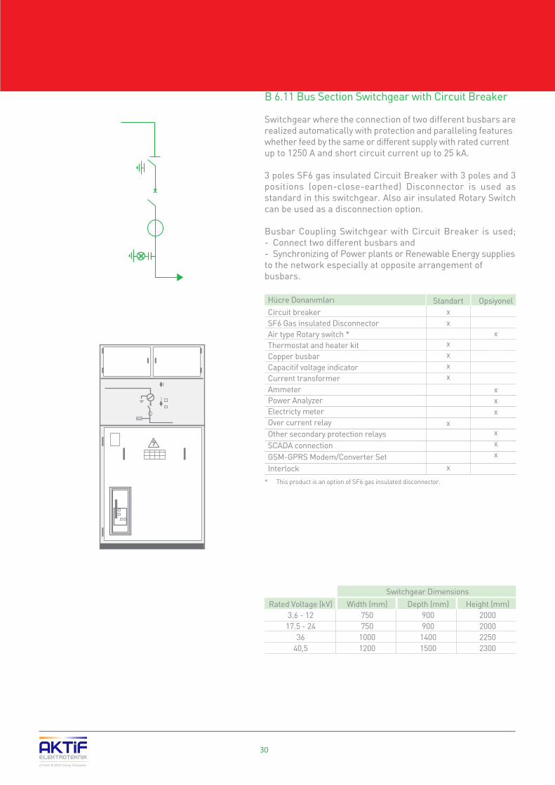
B 6.11 Bus Section Switchgear with Circuit Breaker
Switchgear where the connection of two different busbars are realized automatically with protection and paralleling features whether feed by the same or different supply with rated current up to 1250 A and short circuit current up to 25 kA.
3 poles SF6 gas insulated Circuit Breaker with 3 poles and 3 positions (open-close-earthed) Disconnector is used as standard in this switchgear. Also air insulated Rotary Switch can be used as a disconnection option.
Busbar Coupling Switchgear with Circuit Breaker is used;- Connect two different busbars and- Synchronizing of Power plants or Renewable Energy supplies to the network especially at opposite arrangement of busbars.
Switchgear Dimensions
Rated Voltage (kV)3.6 - 12
17.5 - 2436
40,5
Width (mm)750750
10001200
Height (mm)2000200022502300
Depth (mm)900900
14001500
30
a Friem & Aktif Group Company
B SME series Metal Enclosed Switchgears
Circuit breakerSF6 Gas insulated DisconnectorAir type Rotary switch *Thermostat and heater kitCopper busbarCapacitif voltage indicator Current transformerAmmeterPower AnalyzerElectricty meterOver current relayOther secondary protection relaysSCADA connectionGSM-GPRS Modem/Converter SetInterlock
Standartxx
xxxx
x
x
Opsiyonel
x
xxx
xxx
Hücre Donanımları
* This product is an option of SF6 gas insulated disconnector.

31
a Friem & Aktif Group Company
BSME series Metal Enclosed Switchgears
B 6.12 Bus Rising Switchgear
Switchgear Is used for the connection of Bus section switchgear' busbars by rising up to other busbar system with rated current up to 1250 A and short circuit current up to 25 kA.
Bus riser switchgears may contain 3 poles 3 positioned (open-close-earthed) disconnector or rotary switch in case of switching necessity.
Bus Riser switchgear is used with Bus Section to connect two busbars.
Switchgear Dimensions
Rated Voltage (kV)3.6 - 12
17.5 - 2436
40,5
Width (mm)375500750
1000
Height (mm)2000200022502300
Depth (mm)900900
14001500
SF6 gas insulated disconnectorAir insulated Rotary switchThermostat and Heater KitCopper BusbarVoltage TransformerVoltmeter and Commutator setCurrent TransformerAmmeterPower AnalyzerElectricity Meter
Optionsxx
xxxxxx
Switchgear Equipment Standard
xx

32
a Friem & Aktif Group Company
B SME series Metal Enclosed Switchgears
B 6.13 Bus Voltage Measuring Switchgear
Switchgear is used for obtaining voltage information for the measurement and protection purposes in the metal enclosed busbar with rated current up to 1250 A and short circuit current up to 25 kA with the help of Secondary protection relays and measurement devices like Voltmeter, Power Analyzers, Electricity meters, etc ...
In this switchgear SF6 gas insulated Disconnector with 3 poles and 3 positions (open-close-earthing) is used as standard and also Air insulated rotary switch can be used as an option.
Bus Voltage Measuring Switchgears are used for the receiving of;- Measurement and protection basis Voltage data.- Billing basis Energy consumption measurement.- Providing auxiliary power up to 2.5 kVA in Low Voltage.
* When rotary switcher is used 750 mm for 12 kV and 24 kV, 1000 mm for 36 kV.
Switchgear Dimensions
Rated Voltage (kV)3.6 - 12
17.5 - 2436
40,5
Width (mm)375 *500 *750 *1000
Height (mm)2000200022502300
Depth (mm)900900
14001500
SF6 Gas Insulated DisconnectorAir-Insulated rotary Switch *Thermostat and Heater KitCopper BusbarMedium Voltage FuseVoltage TransformerVoltmeter and commutator setPower AnalyzerElectricity MeterSCADA Connections
Options
x
xxx
Switchgear Equipment Standardx
xxxxx
* This product is an option of SF6 gas insulated disconnector.

33
a Friem & Aktif Group Company
BSME series Metal Enclosed Switchgears
B 6.14 Bus Current Measurement Switchgears
Switchgear with rated current up to 1250 A and short circuit current up to 25 kA in where the current information of the distribution busbars is obtained for the using of Secondary protection relays and measurement devices such as Ammeter, Analyzers and Electricity Meters.
Bus Current Measuring Switchgear is used for the receiving of :- Measurement and Protection basis Current data,- Billing basis Energy consumption measurement.
Switchgear Dimensions
Rated Voltage (kV)3.6 - 12
17.5 - 2436
40,5
Width (mm)750750
10001200
Height (mm)2000200022502300
Depth (mm)900900
14001500
Thermostat and Heater KitCopper BusbarCurrent TransformerAmmeterElectricity meter
OptionalStandardSwitchgear Equipmentxxx
xx

34
a Friem & Aktif Group Company
B SME series Metal Enclosed Switchgears
B 6.15 Current & Voltage Measuring Switchgears
Switchgear with rated current up to 630 A and short circuit current up to 20 kA in which the current and voltage information of the distribution busbars is obtained to use at Secondary protection relays and measurement devices such as Ammeter, Voltmeter, Analyzers and Electricity Meters.
In this switchgear SF6 gas insulated Load Break switch with 3 poles and 3 positions (open-close-earthed) is used as standard. Instead of LBS, SF6 gas insulated disconnector or Rotary switch can be used optionally also to increase the rated current to 1250A, and short circuit current to 25 kA.
Current & Voltage Measuring Switchgear is used for the receiving of; - Main Measurement basis Current and Voltage data,- Billing basis Energy consumption measurement.
Switchgear Dimensions
Rated Voltage (kV)3.6 - 12
17.5 - 2436
Width (mm)750
10001150
Height (mm)200020002250
Depth (mm)900900
1400
SF6 Gas Insulated Load Break SwitchSF6 Gas Insulated Disconnector *Air Insulated rotary Switch * Motor set for spring chargingThermostat and Heater KitCopper BusbarMedium Voltage FuseVoltage TransformerVoltmeter and Commutator setCurrent TransformerAmmeterPower AnalyzerElectricity MeterMotor set for Remote open-closeSCADA ConnectionsGSM/GPRS Modem Converter SetInterlock
OptionalSwitchgear Equipment Standard
* If more current capacity is needed it's possible to use SF6 Disconnector or Rotary Switch instead of LBS.
x
xxxxx
x
x
x
xxx
xx xxx

B 6.16 Surge Arrester Switchgear
It is used on the busbars rated current up to 1250 A and short circuit current up to 25 kA, to protect the system and apparatus against temporary over voltages caused by the lightning surges and switching surges.
Thermostat and Heater KitCopper BusbarSurge Arrestor
Standardxxx
OptionsSwitchgear Equipment
Switchgear Dimensions
Rated Voltage (kV)3.6 - 12
17.5 - 2436
40,5
Width (mm)375500750
1000
Height (mm)2000200022502300
Depth (mm)900900
14001500
35
a Friem & Aktif Group Company
BSME series Metal Enclosed Switchgears

C 1 Metal Clad Switchgears with Single Busbar C 1.1 Compartments C 1.2 Application Areas C 1.3 Advantages C 1.4 Standards Complied C 1.5 Technical Specifications C 1.6 Switchgears Types C 1.6.1 Incoming/Outgoing Switchgears C 1.6.2 Outgoing Switchgears with Vacuum Contactor C 1.6.3 Cable Connection Switchgear C 1.6.4 Bus Section Switchgears C 1.6.5 Bus Riser Switchgear C 1.6.6 Bus Voltage Measuring Switchgears C 1.6.7 Current & Voltage Measuring SwitchgearsC 2 Metal Clad Switchgears with Double Busbar C 2.1 Compartments C 2.2 Application Areas C 2.3 Advantages C 2.4 Standards Complied C 2.5 Technical Specifications C 2.6 Switchgears Types C 2.6.1 Double Bus Incoming / Outgoing Switchgears C 2.6.2 Double Bus Coupling Switchgears C 2.6.3 Double Bus Voltage Measuring Switchgears C 2.6.4 Double Bus Current & Voltage Measuring Switchgears
36
38394141414243444546474849505252535354545556575859

Metal CladSwitchgear

38
C 1 Metal Clad Switchgearswith single Busbar
Metal Clad Switchgears are switching and control cabinets manufactured between 1 kV … 40.5 kV in conformity with IEC 62271-200 standards.
The Metal Clad Switchgears are manufactured from steel structures in vertical position as free-standing which contain withdrawable/cassette type Circuit breakers, Main, distribution and grounding busbars, Current-Voltage Transformers, Protection and Control equipment.
Main structures consist of 3 mm sheet steels and painted with electrostatic powder paint in conformance with RAL codes.
Metal Clad Switchgears manufactured by Aktif Elektroteknik since 1989 as passed the tests successfully in the accredited international laboratories in Europe (CESI/Italy).
SMC series Metal Clad Switchgears are defined with following features according to IEC 62271-200.
� Air insulated� LSC 2B Loss of Service continuity� PM Partition class� AFLR Internal Arc Classification� 4 accessible compartments
a Friem & Aktif Group Company
C SMC series Metal Clad Switchgears

39
c
b
a
d
C 1.1 Compartments
Metal clad Switchgears consist of 4 compartments segregated from each other by grounded metal compartments:
a - Switching Compartmentb - Low Voltage Compartmentc - Busbar Compartmentd - Cable Compartment
a - Switching Compartment
The switching compartment consists of following units:
� Switching Equipments (circuit breaker-contactor, etc.)� Withdrawable truck� Switchgear door contains operating mechanism of truck and earthing switch� Individual and lockable grounded automatic shutters
Switching Compartment may have the following switching equipment according to the project.
� Vacuum circuit breaker� SF6 circuit breaker� Contactor� Fuses
Switching compartment access is controlled by integral design of Metal Clad Switchgear to ensure safe operation according to IEC 62271-200
The following mechanic Interlocks are provided as standard:
� The withdrawal or engagement of the C/B is not possible during the C/B is “On” position� The operation of the C/B is not possible unless it is in service and test position� It is not possible to open the switching compartment door when it is in service position� It is not possible to close the C/B when switching compartment door is open� Closing of earthing switch is not possible if circuit breaker truck is in service position� The operation of the C/B is not possible when earthing switch is closed
a Friem & Aktif Group Company
C SMC series Metal Clad Switchgears
40
a Friem & Aktif Group Company
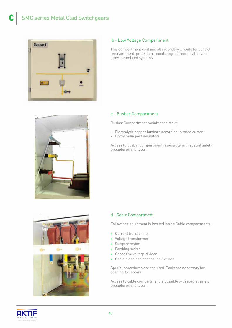
b - Low Voltage Compartment
This compartment contains all secondary circuits for control, measurement, protection, monitoring, communication and other associated systems
c - Busbar Compartment
Busbar Compartment mainly consists of;
- Electrolytic copper busbars according to rated current.- Epoxy resin post insulators
Access to busbar compartment is possible with special safety procedures and tools.
d - Cable Compartment
Followings equipment is located inside Cable compartments;
� Current transformer� Voltage transformer� Surge arrestor� Earthing switch� Capacitive voltage divider � Cable gland and connection fixtures
Special procedures are required. Tools are necessary for opening for access.
Access to cable compartment is possible with special safety procedures and tools.
C SMC series Metal Clad Switchgears

41
C 1.2 Application Areas
� Energy Transmission and Distribution Centers� Hydroelectric Power Plants� Diesel and Natural Gas Power Plants� Transformer Substations� Cement Factories� Auto Industry� Petroleum and Chemical Industry� Iron and Steel Industry� Rolling Mills� Pipelines� Electro Chemical Facilities� Shipyards� Emergency Situation and Stand-by Power Plants� Ore Mines� Railway Substations
C 1.3 Advantages
� LSC2B Maximum Service Continuity � Earthed metal partitions between compartments� Maximum human safety with AFLR internal arc testing feature � Safety electrical and mechanical Interlocks doesn't allow to operational faults� Withdrawable type Vacuum / SF6 Circuit breaker for fast and easy servicing� Earthing system, continuity ensured� Modular compact design, allows any future expansion� Tested short time withstand currentat 31.5 kA / 3 s.� Long operational life - 10.000 switching� Interactive mimic diagram � Proven reliability with unique design� Low maintenance cost� Easy and safety operation� After sale service and spare parts availability
C 1.4 Standards Complied
SMC series Metal Clad Switchgears are manufactured in conforming to following standards:
� IEC 62271-1 : General articles relating to High Voltage Switchgears � IEC 62271-200 : Metal Enclosed Switchgears (1 - 52 kVac]� IEC 62271-100 : Circuit Breakers (1 - 52 kVac]� IEC 62271-102 : Main Circuit and grounding Disconnectors� IEC 62271-105 : AC Switch and Fuse Combinations� IEC 60044-1 : Current Transformers� IEC 60044-2 : Voltage Transformers� IEC 60273 : Insulators� IEC 60051 : Measuring Devices� IEC 60255 : Secondary Protection relays
a Friem & Aktif Group Company
C SMC series Metal Clad Switchgears

C 1.5 Technical Specifications
a Friem & Aktif Group Company
42
C SMC series Metal Clad Switchgears
Note: Full type tests of SMC switchgears up to 31.5 kA are performed at CESI accredited laboratories in Italy.
Technical Specifications
Descriptions
kV
kV
kV
Hz
AAAAAAA
kAkAkA
kAkAkA
ss
kAs
kAss
3,6
10
40
7,2
20
60
12
28
75
24
50
125
LSC 2BAFLRPM
IP 40IP 42IP 20
Rated Voltage (rms)Power frequency withstand Voltage 50 Hz, 1 min (rms) between phases and phase-ground Lightning impulse withstand Voltage 1.2/50 ms (peak) between phases and phase - groundRated frequencyRated (rms) current of switchgears with
Rated short time withstand (rms) current with
Rated short time withstand (peak) current with
Short circuit withstand time
Internal Arc withstand
Earthing Disconnector
Switchgear Structure as per the
Protection Class
Color
Standards complied
Busbars (with natural ventilation)Fan (forced ventilation)
C/B and Disconnector (with natural ventilation)(forced ventilation)
Load break switchesVacuum Contactors (inductive switching)
Vacuum Contactors (capacitive switching)
C/B and DisconnectorsLoad break switchesVacuum Contactors
C/B and DisconnectorsLoad break switchesVacuum Contactors
up to 31.5 kVabove 31.5 kV
CurrentDuration
Rated short time withstand currentDuration (up to 31.5 kA)
(above 31.5 kA)
loss of service continuityinternal arc classification
partition class
when doors are closed - standardoptional
between compartments
SMC 3,6 SMC 7,2
17,5
38
95
SMC 17,5SMC 12 SMC 24
36
70
170
SMC 36
40,5
85
185
SMC 40,5
630 ... 31505000
630 ... 31505000630400250
16 ... 5016 - 20
8
40 ... 12540 - 50
20
31
16 ... 31.51
16 ... 5031
630 ... 31505000
630 ... 31505000630800200
16 ... 5016 - 20
8
40 ... 12540 - 50
20
31
16 ... 31.51
16 ... 5031
16 ... 5031
630 ... 31505000
630 ... 31505000630
--
16 ... 5016 - 20
-
40 ... 12540 - 50
-
31
16 ... 31.51
IEC 62271-200
50 - 60
RAL 9003 / 7035

43
C 1.6 Switchgears Types
� Incoming/Outgoing Switchgear
is the switchgear for incoming and outgoing from the distribution busbar with rated current up to 3150 A and short circuit current up to 50 kA which allows to switch operation during short circuit.
� Outgoing Switchgears with Vacuum Contactor and fuse
is the switchgears used where frequent switching operation is required with rated voltage up to 24 kV and rated current up to 400 A.
� Cable Connection Switchgear
is the switchgear with rated current up to 3150 A and short circuit current up to 50 kA and the incoming distribution connection realized by busbar
� Bus Section Switchgear
is the switchgear with rated current up to 3150 A and short circuit current up to 50 kA where the dividing of the main busbar is needed and allows to switching operation during short circuit.
� Bus Riser Switchgear
is the switchgear used for the purpose of rising the busbar connections to the other busbar level which is divided by the Bus section switchgear, with rated current up to 3150 A and short circuit current up to 50 kA. � Bus Voltage Measuring Switchgear
is the switchgear used for obtaining voltage information for the measurement and protection purposes in the metal clad busbar with rated current up to 3150 A and short circuit current up to 50 kA with the help of Secondary protection relays and measurement devices like Voltmeter, Power Analyzers, Electricity meters... � Current & Voltage Measuring Switchgear
is the switchgear used for obtaining current information for the measurement and protection purposes in the metal clad busbar with rated current up to 3150 A and short circuit current up to 50 kA with the help Secondary protection relays and measurement devices like Ammeter, Power Analyzers, Electricity meters...
Bus Section
Bus Riser
a Friem & Aktif Group Company
Bus VoltageMeasuring
Cable Connection
C SMC series Metal Clad Switchgears
Current & VoltageMeasuring
Outgoing withVacuum Contactor
with fuse
Incoming/Outgoing
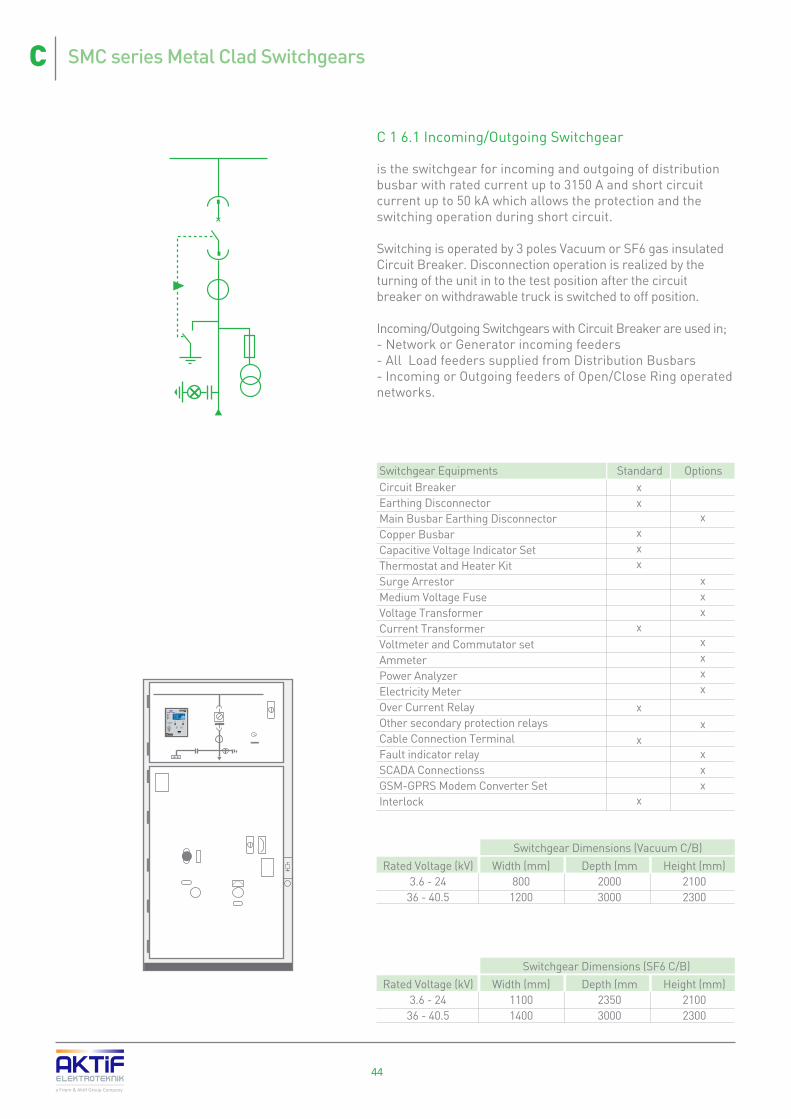
C 1 6.1 Incoming/Outgoing Switchgear
is the switchgear for incoming and outgoing of distribution busbar with rated current up to 3150 A and short circuit current up to 50 kA which allows the protection and the switching operation during short circuit.
Switching is operated by 3 poles Vacuum or SF6 gas insulated Circuit Breaker. Disconnection operation is realized by the turning of the unit in to the test position after the circuit breaker on withdrawable truck is switched to off position. Incoming/Outgoing Switchgears with Circuit Breaker are used in;- Network or Generator incoming feeders- All Load feeders supplied from Distribution Busbars- Incoming or Outgoing feeders of Open/Close Ring operated networks.
Switchgear Dimensions (Vacuum C/B)
Rated Voltage (kV)3.6 - 24
36 - 40.5
Width (mm)800
1200
Height (mm)21002300
Depth (mm20003000
Switchgear Dimensions (SF6 C/B)
Rated Voltage (kV)3.6 - 24
36 - 40.5
Width (mm)11001400
Height (mm)21002300
Depth (mm23503000
Circuit BreakerEarthing DisconnectorMain Busbar Earthing DisconnectorCopper BusbarCapacitive Voltage Indicator SetThermostat and Heater KitSurge ArrestorMedium Voltage FuseVoltage TransformerCurrent TransformerVoltmeter and Commutator setAmmeterPower AnalyzerElectricity MeterOver Current RelayOther secondary protection relaysCable Connection TerminalFault indicator relaySCADA ConnectionssGSM-GPRS Modem Converter SetInterlock
OptionsStandardSwitchgear Equipments
X
ImaxUabVARCLLRC
0
A0
V0.00 k
POWER
TRIPCLOSED
<<<
<<<
I
ORS232
OPEN
DisableNot Avail<Menu>
44a Friem & Aktif Group Company
C SMC series Metal Clad Switchgears
xx
xxx
x
x
x
x
x
xxx
xxxx
x
xxx

45a Friem & Aktif Group Company
C SMC series Metal Clad Switchgears
C 1 6.2 Outgoing Switchgears with Vacuum Contactor
the switchgears used where frequent switching operation is required with rated voltage up to 24 kV and rated current up to 400 A.
For the switching operation 3 poles vacuum contactor is used. Disconnection operation is realized by the turning of the unit in to the test position after the contactor on withdrawable truck switched to off position.
Outgoing Switchgear with contactor is used for feeding of;- Capacitor Banks- Harmonic Filters- Shunt Reactors and- Motors
Switchgear Dimensions
Rated Voltage (kV)3.6 - 12
Width (mm)800
Height (mm)2100
Depth (mm)2000
Vacuum ContactorEarthing disconnectorThermostat and Heater KitCopper BusbarCapacitive Voltage Indicator SetMedium Voltage FusesCurrent TransformersOver Current RelayOther secondary protection relays Test terminalFault indicator deviceSCADA ConnectionsGSM-GPRS Modem Converter SetInterlock
OptionsStandardSwitchgear Equipmentsxxxxx
x
xxxxxxxx

C 1 6.3 Cable Connection Switchgear
Switchgear allows to connect main busbar system from another busbar system up to 3150 A rated current and 50 kA short circuit current.
This switchgear doesn't contain any protection and breaking possibility. The disconnection is possible only by the turning the unit in to the test position to remove the connection busbar from the main distribution busbar after the circuit breaker on supply feeder is switched to off position.
Incoming Switchgears with busbar are used in;- Opposite busbar incoming, fed from the outgoing cubicle at opposite arrangement of switchgears.
Switchgear Dimensions
Rated Voltage (kV)3.6 - 24
36 - 40.5
Width (mm)800
1200
Height (mm)21002300
Depth (mm)20003000
Earthing DisconnectorThermostat and Heater KitCopper BusbarCapacitive Voltage Indicator SetSurge Arrestor *MV FusesVoltage TransformerCurrent TransformerAmmeterPower AnalyzerElectricity MeterTest TerminalCable Connection TerminalSCADA ConnectionsInterlock
OptionsStandardSwitchgear Equipments
46a Friem & Aktif Group Company
C SMC series Metal Clad Switchgears
xxxx
x
x
xxxxxxxx
x

47a Friem & Aktif Group Company
C SMC series Metal Clad Switchgears
C 1 6.4 Bus Section Switchgear
the switchgear with rated current up to 3150 A and short circuit current up to 50 kA where the dividing of the main busbar is needed and allows for switching operation during short circuit.
For the switching operation 3 poles Vacuum or SF6 gas insulated Circuit Breaker is used on withdrawable truck. Disconnection operation is realized by the turning of the unit in to the test position after the circuit breaker on withdrawable truck is switched to off position.
Bus Section Switchgear is used to connect/disconnect two Busbars automatically or with remote switching operation with Secondary Protection.
Switchgear Dimensions (Vacuum C/B)
Rated Voltage (kV)3.6 - 24
36 - 40.5
Width (mm)800
1200
Height (mm)21002300
Depth (mm)20003000
Hücre Ölçüleri (SF6 Gazl› Kesicili)
Rated Voltage (kV)3.6 - 24
36 - 40.5
Width (mm)11001400
Height (mm)21002300
Depth (mm)23503000
X
ImaxUabVARCLLRC
0
A0
V0.00 k
POWER
TRIPCLOSED
<<<
<<<
I
ORS232
OPEN
DisableNot Avail<Menu>
Circuit BreakerThermostat and Heater KitCopper BusbarCapacitive Voltage Indicator SetCurrent TransformerAmmeterPower AnalyzerElectricity MeterOver Current RelayOther secondary protection relay Test TerminalSCADA ConnectionsGSM-GPRS Modem Converter SetInterlock
OptionsStandardSwitchgear Equipments
xxxxx
x
x
xxx
xxxx

C 1 6.5 Bus Riser Switchgear
is the switchgear used for the purpose of rising the busbar connections to the other busbar level which is divided by the Bus section switchgear, with rated current up to 3150 A and short circuit current up to 50 kA.
Voltage transformers can be used optionally in this switchgear to obtain voltage information.
Bus Riser Switchgear is used with Bus Section Switchgear.
Switchgear Dimensions
Rated Voltage (kV)3.6 - 24
36 - 40.5
Width (mm)500800
Height (mm)21002300
Depth (mm)20003000
Thermostat and Heater KitCopper BusbarVoltage Transformer and fuseVoltmeter and Commutator set
OptionsStandardSwitchgear Equipment
48a Friem & Aktif Group Company
C SMC series Metal Clad Switchgears
xx
xx

49a Friem & Aktif Group Company
C SMC series Metal Clad Switchgears
C 1.6.6 Bus Voltage Measuring Switchgears
Switchgear is used for obtaining voltage information for the measurement and protection purposes in the metal clad busbar with rated current up to 3150 A and short circuit current up to 50 kA with the help of Secondary protection relays and measurement devices like Voltmeter, Power Analyzers, Electricity meters, etc ...
Disconnection is realized by the turning of the unit in to the test position.
Bus Voltage Measuring Switchgears are used in :- Measurement and protection basis Voltage data reading.- Billing basis Energy consumption measurement reading.- Providing auxiliary power up to 2.5 kVA in Low Voltage.
Switchgear Dimensions
Rated Voltage (kV)3.6 - 24
36 - 40.5
Width (mm)800
1200
Height (mm)21002300
Depth (mm)20003000
Thermostat and Heater KitCopper BusbarMedium Voltage FusesVoltage TransformerVoltmeter and Commutator SetPower AnalyzerSCADA ConnectionsInterlock
OptionsStandardSwitchgear Equipment
xxxx
x
xxx

50a Friem & Aktif Group Company
C SMC series Metal Clad Switchgears
C 1.6.7 Current & Voltage Measuring Switchgears
Switchgear with rated current up to 3150 A and short circuit current up to 50 kA in which the current and voltage information of the distribution busbars are obtained by using Secondary protection relays and measurement devices such as Ammeter, Voltmeter, Analyzers and Electricity Meters. Disconnecting operation is not requested in such kind of feeders to be able to measure the energy consumption continuously.
Metering Switchgears are used for the receiving of; - Main Measurement basis Current and Voltage data.- Billing basis Energy consumption measurement.
Switchgear Dimensions
Rated Voltage (kV)3.6 - 24
36 - 40.5
Width (mm)800
1200
Height (mm)21002300
Depth (mm)20003000
Thermostat and Heater KitCopper BusbarMedium Voltage FusesVoltage TransformerCurrent TransformerElectricity MeterVoltmeter and Commutator SetAmmeterPower AnalyzerSCADA ConnectionsInterlock
OptionsStandardSwitchgear Equipment
xxxxxxx
x
xxx

51
a Friem & Aktif Group Company
C SMC series Metal Clad Switchgears

52
a Friem & Aktif Group Company
C 2 Metal Clad Switchgears with Double BusbarSwitchgears with double busbar are used for balancing the load for the medium voltage distribution systems that feed from two different sources by taking the capacity into the consideration. Furthermore, it is also used for utilizing the busbar of one source when the other source cannot get energy to its busbar due to a power cut-off. It makes advantage to distribution system for the continuity of energy supply.
C 2.1 Compartments
Metal clad Switchgears with double busbar system contain the following compartments which are segregated from each other with grounded metal compartment.
a- Switching Equipment Compartmentb- Low Voltage Command Compartmentc- Busbar Compartmentsd- Cable Compartment
a- Switching Equipment Compartment
Switching Compartment consists of the following units:
� Switching Equipment (Circuit breaker-contactor, etc.)� Elevator type of withdrawable truck� Switchgear door contains operating mechanism of truck and earthing switch� Individual and lockable grounded metal separator
Switching compartment may have the following Switching Equipment as per the necessity of the project
� Vacuum Circuit breaker� SF6 Circuit breaker� Contactor� Fuses
In order to provide operational safety, the metal clad Switchgears are manufactured in line with the criteria defined in IEC 62271-200
Access to Switching compartment is controlled by integral design of Metal Clad Switchgear to ensure safe operation according to IEC 62271-200
The following mechanic Interlocks are provided as standard:
� The withdrawal or engagement of the C/B is not possible during the C/B is “On” position� The operation of the C/B is not possible unless it is in service and test position� It is not possible to open the switchgear door when it is in service position� It is not possible to close the C/B when switching compartment door is open.� Closing of earthing switch is not possible if circuit breaker truck is in service position� The operation of the CB is not possible when earthing switch is closed.
c
c
b
ad
b
a
C SMC series Metal Clad Switchgears

53
a Friem & Aktif Group Company
b- Low Voltage Compartment
This compartment contains all secondary circuits for control, measurement, protection, monitoring, communication and other associated systems.
c- Busbar Compartment
Busbar Compartment mainly consists of;
Electrolytic copper busbars according to rated current.Epoxy resin post insulators
Access to busbar compartment is possible with special safety procedures and tools.
d- Cable Compartment
Followings equipments are located inside Cable compartments;
� Current transformer� Voltage transformer� Surge arrestor� Earthing switch� Capacitive voltage divider � Cable gland and connection fixtures
Access to Cable compartment is possible with special safety procedures and tools.
C 2.2 Application Areas
The industrial or distribution companies that get their energy from two different sources utilize double busbar systems in order to be able to perform load balancing at the main busbar.
In this application, bus A or bus B distributes uninterrupted power and also balances the loads on two busbars.
� Energy Distribution Centers� Industrial Zones � Metallurgy and Cement Factories� Petrochemical Plants
C 2.3 Advantages
� Minimum influences from the faults occurring energy feeding points.� More power distribution from a single energy center� Balancing energy consumption rates between two busbars in systems that are fed by two sources and providing uninterrupted power distribution.
C SMC series Metal Clad Switchgears

54
a Friem & Aktif Group Company
C 2.4 Standards Complied
SMC series Metal Clad Switchgears are manufactured in conformance with the following standards:
� IEC 62271-1 : General articles relating to High Voltage Switchgears� IEC 62271-200 : Metal Enclosed Switchgears (1 - 52 kVac)� IEC 62271-100 : Circuit Breakers (1 - 52 kVac)� IEC 62271-102 : Main Circuit and Earthing Disconnector � IEC 62271-105 : AC Switches and Fuse Combinations � IEC 60044-1 : Current Transformers� IEC 60044-2 : Voltage Transformers� IEC 60273 : Insulators� IEC 60051 : Measuring Devices� IEC 60255 : Secondary Protection relays
C 2.5 Technical Specifications
C SMC series Metal Clad Switchgears
Technical Specifications
Descriptions
kV
kV
kV
Hz
AAAAAAA
kAkAkA
kAkAkA
ss
kAs
kAss
3,6
10
40
7,2
20
60
12
28
75
24
50
125
LSC 2BAFLRPM
IP 40IP 42IP 20
Rated Voltage (rms)Power frequency withstand Voltage 50 Hz, 1 min (rms) between phases and phase-ground Lightning impulse withstand Voltage 1.2/50 ms (peak) between phases and phase - groundRated frequencyRated (rms) current of switchgears with
Rated short time withstand (rms) current with
Rated short time withstand (peak) current with
Short circuit withstand time
Internal Arc withstand
Earthing Disconnector
Switchgear Structure as per the
Protection Class
Color
Standards complied
Busbars (with natural ventilation)(forced ventilation)
C/B and Disconnector (with natural ventilation)(forced ventilation)
Load break switchesVacuum Contactors (inductive switching)
Vacuum Contactors (capacitive switching)
C/B and DisconnectorsLoad break switchesVacuum Contactors
C/B and DisconnectorsLoad break switchesVacuum Contactors
up to 31.5 kVabove 31.5 kV
CurrentDuration
Rated short time withstand currentDuration (up to 31.5 kA)
(above 31.5 kA)
loss of service continuityinternal arc classification
partition class
when doors are closed - standardoptional
between compartments
SMC 3,6 SMC 7,2
17,5
38
95
SMC 17,5SMC 12 SMC 24
36
70
170
SMC 36
40,5
85
185
SMC 40,5
630 ... 31505000
630 ... 31505000630400250
16 ... 5016 - 20
8
40 ... 12540 - 50
20
31
16 ... 31.51
16 ... 5031
630 ... 31505000
630 ... 31505000630800200
16 ... 5016 - 20
8
40 ... 12540 - 50
20
31
16 ... 31.51
16 ... 5031
16 ... 5031
630 ... 31505000
630 ... 31505000630
--
16 ... 5016 - 20
-
40 ... 12540 - 50
-
31
16 ... 31.51
IEC 62271-200
50 - 60
RAL 9003 / 7035

55
a Friem & Aktif Group Company
C 2.6 Switchgears Types
� Double Bus Incoming/Outgoing Switchgear
Is the switchgear with rated current up to 3150 A and short circuit current up to 50 kA where the power incoming and outgoing realized by busbar and switching operation can be realized in short circuit situation. � Double Bus Coupling Switchgear
Is the switchgear with rated current up to 3150 A and short circuit current up to 50 kA where the energy is supplied from two different sources.
� Double Bus Voltage Measuring Switchgear
It is used for obtaining voltage information for the measurement and protection purposes in the metal clad busbar with rated current up to 3150 A and short circuit current up to 50 kA with the help of Secondary relays and measurement devices such as Voltmeter, analyzers and Electricity Meters.
� Double Bus Current & Voltage Measuring Switchgear
Switchgear with rated current up to 3150 A and short circuit current up to 50 kA in which the current and voltage information of the distribution busbars are obtained by using Secondary protection relays and measurement devices such as Ammeter, Voltmeter, Analyzers and Electricity Meters.
Double BusCoupling
Double BusIncoming / Outgoing
C SMC series Metal Clad Switchgears
Double BusVoltage Measuring
Double BusCurrent & Voltage
Measuring

56
a Friem & Aktif Group Company
C SMC series Metal Clad Switchgears
C 2.6.1 Double Bus Incoming / Outgoing Switchgears
Is the switchgear with rated current up to 3150 A and short circuit current up to 50 kA where the energy incoming and outgoing realized by busbar and switching operation can be realized in the short circuit situation, with full protection frame.
Switching operation is realized by vacuum or SF6 gas insulated Circuit Breaker with 3 poles. The disconnecting operation is realized when withdrawable truck with the busbar on it shall be turned to the test position. The Bus connection is changed by lift.
Incoming Switchgear with Circuit Breaker is used in;- Distribution Busbars of Network and Generator Incoming feeders- Any Load supply feeders of Distribution Busbars and- Incoming and Outgoing of Open/Close Ring operated Networks.
Switchgear DimensionsRated Voltage (kV)
3.6 - 2436 - 40.5
Width (mm)800
1200
Height (mm)21002450
Depth (mm)23503500
Withdrawable Circuit BreakerEarthing DisconnectorThermostat and Heater KitCopper BusbarCapacitive Voltage Indicator SetSurge Arrestor Voltage TransformerVoltmeter Commutator SetCurrent TransformerAmmeterPower AnalyzerElectricity MeterOver Current RelayOther secondary protection relays Test TerminalCable Connection TerminalSCADA ConnectionsGSM-GPRS Modem Converter SetInterlock
Options
xxx
xxx
xx
xx
Standardxxxxx
x
x
x
x
Switchgear Equipment
X
ImaxUabVARCLLRC
0
A0
V0.00 k
POWER
TRIPCLOSED
<<<
<<<
I
ORS232
OPEN
DisableNot Avail<Menu>

57
a Friem & Aktif Group Company
C SMC series Metal Clad Switchgears
C 2.6.2 Double Bus Coupling Switchgear
Is the switchgear with rated current up to 3150 A and short circuit current up to 50 kA where the energy is supplied from two different sources, with full protection frame. Switching operation is realized by Vacuum or SF6 gas insulated Circuit Breaker with 3 poles. The disconnecting operation is realized when withdrawable truck with the busbar on it shall be turned to the test position.
Double Bas Coupling Switchgears are used to connect two Busbars automatically or with local/remote switching operation.
Withdrawable Circuit BreakerEarthing DisconnectorThermostat and Heater KitCopper BusbarCurrent TransformerAmmeterPower AnalyzerElectricity MeterOver Current RelayOther secondary protection relays Test TerminalSCADA ConnectionsGSM-GPRS Modem Converter SetInterlock
Options
x
xxx
xxxx
Switchgear Equipment Standardx
xxx
x
x
X
ImaxUabVARCLLRC
0
A0
V0.00 k
POWER
TRIPCLOSED
<<<
<<<
I
ORS232
OPEN
DisableNot Avail<Menu>
Switchgear DimensionsRated Voltage (kV)
3.6 - 2436 - 40.5
Width (mm)800
1200
Height (mm)21002450
Depth (mm)23503500

58
a Friem & Aktif Group Company
C SMC series Metal Clad Switchgears
C 2.6.3 Double Bus Voltage Measuring Switchgears
Switchgear is used for obtaining voltage information for the measurement and protection purposes in the metal clad busbar with rated current up to 3150 A and short circuit current up to 50 kA with the help of Secondary protection relays and measurement devices like Voltmeter, Power Analyzers, Electricity meters, etc ...
Disconnection is realized by the turning of the unit in to the test position.
Bus Voltage Measuring Switchgears are used in :- Measurement and protection basis Voltage data reading.- Billing basis Energy consumption measurement.- Providing auxiliary power up to 2.5 kVA in Low Voltage.
Thermostat and Heater KitCopper BusbarMedium Voltage FusesVoltage TransformerVoltmeter and Commutator SetPower AnalyzerSCADA ConnectionsInterlock
Options
xxx
Standardxxxx
x
Switchgear Equipment
Switchgear DimensionsRated Voltage (kV)
3.6 - 2436 - 40.5
Width (mm)800
1200
Height (mm)21002450
Depth (mm)23503500

59
a Friem & Aktif Group Company
C SMC series Metal Clad Switchgears
C 2.6.4 Double Bus Current & Voltage Measuring Switchgears
Switchgear with rated current up to 3150 A and short circuit current up to 50 kA in which the current and voltage information of the distribution busbars are obtained by using Secondary protection relays and measurement devices such as Ammeter, Voltmeter, Analyzers and Electricity Meters. Disconnecting operation is not requested in such kind of feeders to be able to measure the energy consumption continuously.
Metering Switchgears are used for the receiving of; - Main Measurement basis Current and Voltage data.- Billing basis Energy consumption measurement.
Thermostat and Heater KitCopper BusbarMedium Voltage FusesVoltage TransformerVoltmeter and Commutator SetPower AnalyzerSCADA ConnectionsInterlock
Options
xxx
Standardxxxx
x
Switchgear Equipment
Switchgear DimensionsRated Voltage (kV)
3.6 - 2436 - 40.5
Width (mm)800
1200
Height (mm)21002450
Depth (mm)23503500

D 1 CompartmentsD 2 Application AreasD 3 AdvantagesD 4 Standards CompliedD 5 Technical SpecificationsD 6 Switchgears Types D 6.1 L type Line Disconnecting Unit D 6.2 F type Transformer Protection Unit with Circuit Breaker D 6.3 E type Cable Connection Unit with Earthing Disconnector D 6.4 T type 200 A Transformer Protection Unit with Circuit Breaker D 6.5 C type 630 A or 1250 A Line Protection Unit with Circuit Breaker D 6.6 U1 / U3 type 630 A Bus Coupling Unit with Disconnector D 6.7 U2 type 630 A Bus Coupling Unit with Disconnector D 6.8 UCB type 630 A Bus Coupling Unit with Disconnector D 6.9 Q type Measurement Unit with Circuit Breaker D 6.10 M type Measurement UnitD 7 Sample Busbar Designs with RMU
60
6363646465676869707172737475767778

GasInsulatedRMUs

62
TPR6 series gas insulated modular RMUs are the switching and control Switchgears are manufactured in conformity with IEC 62271-200 standards.
TPR6 series gas insulated RMUs are used on the medium voltage distribution busbars with rated voltage from 1 kV to 40.5 kV, with the rated current from 200 A up to 1250 A and short time withstand current up to 25 kA.
TPR6 series gas Insulated RMUs are defined with following features:
� Gas Insulated� Partition Class PM� AFL and AFLR Internal Arc Classification
a Friem & Aktif Group Company
D TPR6 series Gas Insulated RMUs
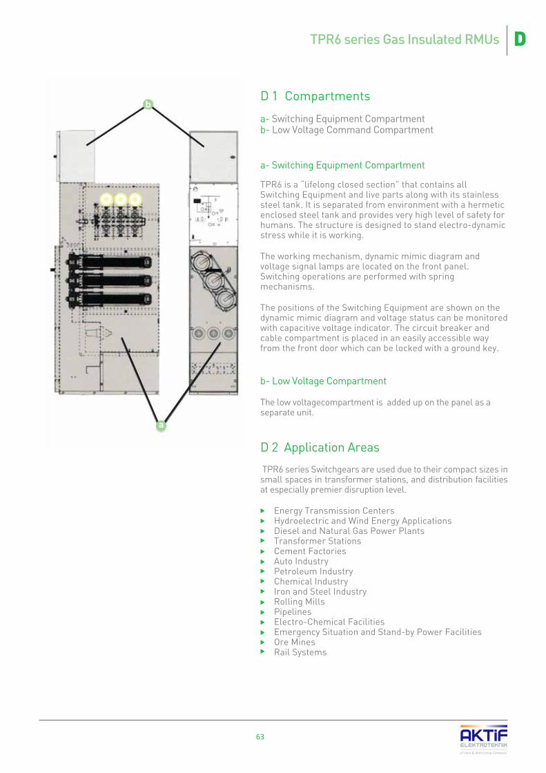
63
D 1 Compartments
a- Switching Equipment Compartmentb- Low Voltage Command Compartment
a- Switching Equipment Compartment TPR6 is a “lifelong closed section” that contains all Switching Equipment and live parts along with its stainless steel tank. It is separated from environment with a hermetic enclosed steel tank and provides very high level of safety for humans. The structure is designed to stand electro-dynamic stress while it is working.
The working mechanism, dynamic mimic diagram and voltage signal lamps are located on the front panel. Switching operations are performed with spring mechanisms.
The positions of the Switching Equipment are shown on the dynamic mimic diagram and voltage status can be monitored with capacitive voltage indicator. The circuit breaker and cable compartment is placed in an easily accessible way from the front door which can be locked with a ground key.
b- Low Voltage Compartment
The low voltagecompartment is added up on the panel as a separate unit.
D 2 Application Areas
TPR6 series Switchgears are used due to their compact sizes in small spaces in transformer stations, and distribution facilities at especially premier disruption level.
� Energy Transmission Centers� Hydroelectric and Wind Energy Applications� Diesel and Natural Gas Power Plants� Transformer Stations� Cement Factories� Auto Industry� Petroleum Industry� Chemical Industry� Iron and Steel Industry� Rolling Mills� Pipelines� Electro-Chemical Facilities� Emergency Situation and Stand-by Power Facilities� Ore Mines� Rail Systems
a Friem & Aktif Group Company
b
a
DTPR6 series Gas Insulated RMUs

64
a Friem & Aktif Group Company
D 3 Advantages
� Grounded metal separation between the sections� Maximum human safety with AFL and AFRL internal arc testing feature � Safe electrical and mechanical Interlock systems do not permit for operational faults� Grounding system with ensured continuity � Modular design, allowing additions to the system� Tested short time withstand current is 21 kA.� Interactive mimic diagram � Proven reliability with unique design for the operation and personnel safety� No maintenance requirement� Suitable for remote monitoring and remote applications� No need for addition of SF6 gas for 30 years due to the sealing� Working without being effected from humid, dusty and dirty environments.
D 4 Standards Complied
The RMU series Switchgears are manufactured in conforming to the following standards:
� IEC 62271-1 : General articles relating to high voltage Switchgears� IEC 62271-200 : Metal enclosed Switchgears (1 - 52 kVac)� IEC 62271-100 : Breakers (1 - 52 kVac)� IEC 62271-102 : Main Circuit and Grounding Separators� IEC 62271-105 : AC Switching and Circuit Breaker Combinations � IEC 60044-1 : Current Transformers� IEC 60044-2 : Voltage Transformers� IEC 60273 : Insulators� IEC 60051 : Measuring Devices� IEC 60255 : Secondary Protection relays
D TPR6 series Gas Insulated RMUs

D 5 Technical Specifications
a Friem & Aktif Group Company
65
DTPR6 series Gas Insulated RMUs
Note: Full type tests of TPR6 switchgears up to 25 kA are performed at CESI accredited laboratories in Italy.
63063016323257
1,000 op. / M1 cl.100 op. at P.F.= 0.7 / E3 cl.
1.000 op. / M1 cl.
Making capacity x 5 / E2 cl.
10,000 op. / M2 cl.
E2 cl.
2,000 op. / M1 cl.
E1 cl.
O - 0,3 s - CO - 3 min - CO55 oC40 oC-25 oC% 95
1000 m.RAL 9003
Technical Specifications
DescriptionskV
kV
kV
kV
kVHzA
kAs
kAIPIPkAkAAAAAAAA
7,2
20
23
60
70
24
50
60
125
145
Rated Voltage (rms)Power frequency withstand Voltage 50 Hz, 1 min (rms) between phasesPower frequency withstand Voltage 50 Hz, 1 min (rms) phase to groundLightning impulse withstand voltage 1.2/50 ms (peak) between phasesLightning impulse withstand voltage 1.2/50 ms(peak) phase to groundRated frequencyRated currentRated short time withstand current (Ik)Rated duration of short circuit (tk)Rated peak withstand current (making capacity) Protection degree (front side)Protection degree (M.V. compartment)Internal arc withstand current Making & Breaking on fuse switch (F module)Rated transfer current at breaking (F module)Active load breaking current (disconnectors)Closed loop breaking current (disconnectors)No-load transformer breaking current (disconnectors)Cable charging breaking current (disconnectors)Line charging breaking current (disconnectors)Earth fault breaking current (disconnectors)Number of Mechanical operations (disconnectors)Number of Electrical operations (disconnectors)Number of Mechanical operations (earthing switch)Number of Electrical operations(earthing switch)Number of Mechanical operations(C module circuit breaker)Number of Electrical operations(C module circuit breaker) Number of Mechanical operations(T module circuit breaker)Number of Electrical operations(T module circuit breaker) Sequence of process (for Circuit Breaker)Maximum ambient temperatureAllowed temperature differenceMinimum ambient temperature Relative humidityAltitude (max.)Color
TPR6 7,2
17,5
38
45
95
110
TPR6 17,5TPR6 12 TPR6 24
36
70
80
170
195
TPR6 36
40,5
95
110
185
210
TPR6 40,5
12
42
48
95
110
TPR6 12*
12
28
32
75
85
630 - 125050 - 60
16-20-25 12,5-16-203
2,5 x Ik
3x67
16 - 2025
210025
180025
180025
160020
140020
84020
840

TPR6 RMU units are used in any type connection like disconnector - fuse combination, disconnector - circuit breaker combination; in protection with secondary protection relays and metering in MV. Mechanism types in TRP6 series RMUs are as below.
D 5.1 CB6 and TCB6 type Circuit Breaker Mechanism
For circuit breaker applications of TPR6 series RMUs with rated current of 200 A and 630 A, CB6 type circuit breakers are used up to rated voltage 24 kV and TCB type circuit breakers are used above rated voltage 24 kV.
D 5.2 LT Type Disconnector Mechanisms
This type of disconnector mechanisms are used L, U2, Q and U2 modules of TPR6 series RMUs only in 36 and 40.5 kV rated voltages.
D 5.3 3D Type Disconnector Mechanisms
This type of disconnector mechanisms are used in circuit breakers with shunt opening coil of F module.
D 5.4 Mechanism Selection
* Every letter below the unit describes the function of the module. Units may expandable from left, right or both sides in option “L”, and from top in option “K” with the connection of cables or busbars.
** Option B is the same of option “l” but the cable connection is not inside a metal housing.
66
a Friem & Aktif Group Company
Avaiable Options0+IBK
No enlargement from right or leftEnlargement is possibleCable entry or exit from the sideCable entry or exit from the sideBusbar or cable entry exit from the top
Operational Mechanism Options
Rated Voltage Unit Type Disconnector Earthing Disconnector Circuit Breaker
Up to 24 kV
36 kV - 40.5 kV
L *FCTU1 *U2EMIL *FCU1 *U2EMIQ
LT3D
LT
LT3DLTLTLT
LT
CB6CB6
CB6E**-
E--
--
-
-----TCB-TCB---TCB
---
---
LT type separatormechanism
CB6 type breakermechanism
3D type separatormechanism
D TPR6 series Gas Insulated RMUs

67
a Friem & Aktif Group Company
D 6 RMU Types� L type Line Disconnector Unit
It is used as line in with disconnector in the distributions centers where RMU units are utilized.
� F type Transformer Protection Unit with Circuit Breaker
It is used in the distribution centers with a circuit breaker disconnector, where RMU is utilized, for the purpose of protection of transformers with capacity of up to 400 kVA or up to 1600 kVA, providing that it is located in the same place.
� E type Cable Connection Unit with Earthing Disconnector
In the distribution centers where RMU is used, it is utilized for making an entry to the RMU busbar without needing any switching element.
� T type Transformer Protection Unit with 200 A Disconnector
In the distribution centers where RMU is used, it is utilized for the protection of transformers with a 200 A Circuit Breaker and secondary protection relays.
� C type Line Protection Unit with 630 A Circuit Breaker
In the distribution centers where RMU is used, it is utilized for the protection of lines with a 630 A Circuit Breaker and secondary protection relays.
� U1 type Bus Coupling Unit with 630 A Disconnector
In the distribution centers where RMU is used, it is utilized for connecting two RMU busbars without secondary protection but with 630 A disconnector.
� U2 type Bus Coupling Unit with 630 A Circuit Breaker
In the distribution centers where RMU is used, it is utilized for connecting two RMU busbars with secondary protection with 630 A Circuit Breaker and disconnector by providing earthing option.
� U3 type Bus Coupling Unit with 630 A Disconnector
In the distribution centers where RMU is used, it is utilized for connecting two RMU busbars without protection but with 630 A disconnector and earthing disconnector.
� UCB type Bus Coupling Unit with 630 A Circuit Breaker
In the distribution centers where RMU is used, it is utilized for connecting two RMU busbars with secondary protection with 630 A Circuit Breaker.
� Q type Measuring Unit with Circuit Breaker (for 36 kV)
These are the RMU units that contain the meter for the invoicing purposes only at 36 kV level in distribution centers where a RMU is used.
� M type Measuring Unit
These are the units that contain the meter for the invoicing purposes in distribution centers where a RMU is used.
M typeMeasuring
L typeLine Disconnector
F type TransformerProtection withCircuit Breaker
E type CableConnection with
Earthing Disconnector
U1 type Bus Coupling with630 A Disconnector
C type Line Protection with
630 A Circuit Breaker
T type TransformerProtection with
200 A Circuit Breaker
U2 typeBus Coupling with630 A Circuit Breaker
UCB typeBus Coupling with630 A Circuit Breaker
Q typeMeasuring with
Circuit Breaker (for 36 kV)
DTPR6 series Gas Insulated RMUs
U3 type Bus Coupling with630 A Disconnector

68
a Friem & Aktif Group Company
D 6.1 L type Line Disconnector Unit
It is used within the open or closed ring structure of the wind mill Power Plants, energy distribution companies and factories that have number of scattered transformers and also within the RMU medium voltage distribution centers of energy distribution systems as a ring Incoming Outgoing unit which is not considered to be need for secondary protection.
When the Disconnector mechanism is selected with a motor, remote opening and closing process can be carried out.
The L type RMU can be selected to permit expansion to the right or left. Furthermore, cable and busbar connection from the top is also possible.
* It is alternative of LT type Operating Mechanism
K
0
+
I
0
+
I
Pressure GageLT Type Operating MechanismCapacitive Voltage Indicator Set3D Type Operating Mechanism*Opening Disconnector Coil (for 3D Type)Disconnector auxiliary contactsEarthing Disconnector auxiliary contactsMotor for Disconnector spring ChargingDisconnector Interlock (Open)Earthing Disconnector Interlock (Close)Other secondary protection relay Disconnector Key LockEarthing Disconnector Key LockLV Control PanelShort Circuit Lamp IndicatorEarthing Fault Lamp Indicator
Options
xxxxxxxxxxxxxx
Switchgear Equipment Standardxxx
* Height of the unit is 1500mm when used together with a C Type module
Switchgear Dimensions
Rated Voltage (kV)1 - 24
36 - 40.5
Width (mm)350425
Height (mm)1200 / 1500 *
1830
Depth (mm)717912
D TPR6 series Gas Insulated RMUs
Avaiable Options0+IK
Not expandable to the right or leftExpandableSide Cable Entry and OutletBusbar or cable entry-outlet from the top

69
a Friem & Aktif Group Company
D 6.2 F type Transformer Protection Unit with Circuit Breaker
While providing protection, it is used for feeding the transformers from the medium voltage distribution centers with RMU at energy distribution systems of medium voltage that have open or close ring structured.
When the Disconnector mechanism is selected with a motor, remote opening and closing process can be carried out.
The F type RMU can be selected to permit expansion to the right or left. Furthermore, cable and busbar connection from the top is also possible.
K
0
+
I
0
+
I
Pressure GageCapacitive Voltage Indicator Set3D Type Operating Mechanism *Opening Disconnector Coil (for 3D Type)Disconnector auxiliary contactsEarthing Disconnector auxiliary contactsMotor for Disconnector spring ChargingDisconnector Interlock (Open)Earthing Disconnector Interlock (Close)Other secondary protection relayDisconnector Key LockEarthing Disconnector Key LockLV Control PanelShort Circuit Lamp IndicatorEarthing Fault Indicator Lamp
Options
xxxxxxxxxxxx
Switchgear Equipment Standardxxx
* Height of the unit is 1500mm when used together with a C Type module
Switchgear Dimensions
Rated Voltage (kV)1 - 24
36 - 40.5
Width (mm)350425
Height (mm)1200 / 1500 *
1830
Depth (mm)717912
DTPR6 series Gas Insulated RMUs
* It is alternative of LT type Operating Mechanism
Avaiable Options0+IK
Not expandable to the right or leftExpandableSide Cable Entry and OutletBusbar or cable entry-outlet from the top
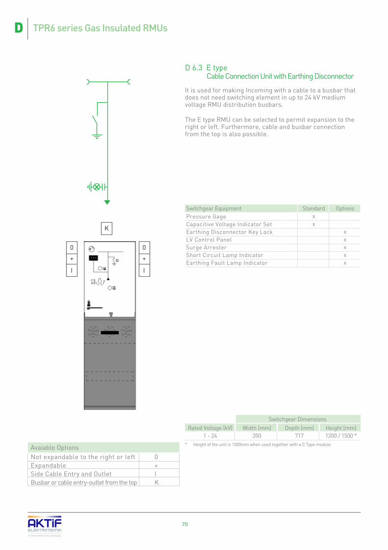
Avaiable Options0+IK
Not expandable to the right or leftExpandableSide Cable Entry and OutletBusbar or cable entry-outlet from the top
70
a Friem & Aktif Group Company
D 6.3 E type Cable Connection Unit with Earthing Disconnector
It is used for making Incoming with a cable to a busbar that does not need switching element in up to 24 kV medium voltage RMU distribution busbars.
The E type RMU can be selected to permit expansion to the right or left. Furthermore, cable and busbar connection from the top is also possible.
K
0
+
I
0
+
I
Pressure GageCapacitive Voltage Indicator SetEarthing Disconnector Key LockLV Control PanelSurge ArresterShort Circuit Lamp IndicatorEarthing Fault Lamp Indicator
Options
xxxxx
Switchgear Equipment Standardxx
D TPR6 series Gas Insulated RMUs
* Height of the unit is 1500mm when used together with a C Type module
Switchgear Dimensions
Rated Voltage (kV)1 - 24
Width (mm)350
Height (mm)1200 / 1500 *
Depth (mm)717

71
a Friem & Aktif Group Company
D 6.4 T type Transformer Protection Unit with 200 A Disconnector
It is used in medium voltage open or closed ring distribution structures with up to 24 kV RMU units for feeding transformers while ensuring protection with 200 A Circuit Breaker and secondary protection relay from medium voltage distribution center.
The T type RMU can be selected to permit expansion to the right or left. Furthermore, cable and busbar connection from the top is also possible.
K
0
+
I
0
+
I
Pressure GageCapacitive Voltage Indicator SetCB6 Type Operating Mechanism*200 A Vacuum BreakerCircuit reaker Opening RelayCircuit Breaker auxiliary contactsCircuit Breaker central Interlock system*Disconnector auxiliary contactsEarthing Disconnector auxiliary contactsDisconnector Interlock (Open)Earthing Disconnector Interlock (Open)Earthing Disconnector Interlock (Close)Disconnector Key LockEarthing Disconnector Key LockSecondary protection relayLow Voltage relayBreaker Engine for setting the springBreaker Closing RelayLV Control PanelShort Circuit Lamp IndicatorEarthing Fault Lamp IndicatorCurrent Transformer Cable Connection
Options
xxxxxxxxxxxxxxx
Switchgear Equipment Standardxxxxxxx
* when the Disconnector is off and breaker is on, lock key can be moved
DTPR6 series Gas Insulated RMUs
Avaiable Options0+IK
Not expandable to the right or leftExpandableSide Cable Entry and OutletBusbar or cable entry-outlet from the top
* Height of the unit is 1500mm when used together with a C Type module
Switchgear Dimensions
Rated Voltage (kV)1 - 24
Width (mm)350
Height (mm)1200 / 1500 *
Depth (mm)717

72
a Friem & Aktif Group Company
D 6.5 C type Line Protection Unit with 630 A or 1250 Circuit Breaker
It is used in medium voltage open or closed ring distribution structures with the RMU units for line Incoming of the medium voltage distribution centers with 630 A or 1250 A Circuit Breaker and secondary protection relay to ensure busbar Incoming.
The C type RMU can be selected to permit expansion to the right or left. Furthermore, cable and busbar connection from the top is also possible.
K
0
+
I
0
+
I
Pressure GageCapacitive Voltage Indicator SetCB6 Type Operating Mechanism *630A/1250A Vacuum BreakerBreaker Opening RelayBreaker auxiliary contactsBreaker central Interlock system *Disconnector auxiliary contactsEarthing Disconnector auxiliary contactsDisconnector Interlock (Open)Earthing Disconnector Interlock (Open)Earthing Disconnector Interlock (Close)Disconnector Key LockEarthing Disconnector Key LockSecondary protection relayLow Voltage relaymotor for Disconnector spring ChargingBreaker Closing RelayLV Control PanelShort Circuit Lamp IndicatorEarthing Fault Lamp IndicatorCurrent Transformer Cable Connection
Options
xxxxxxxxxxxxxxx
Switchgear Equipment Standartxxxxxxx
* when the Disconnector is off and breaker is on, lock key can be moved
D TPR6 series Gas Insulated RMUs
Avaiable Options0+IK
Not expandable to the right or leftExpandableSide Cable Entry and OutletBusbar or cable entry-outlet from the top
* Height of the unit is 1500mm when used together with a C Type module
Switchgear Dimensions (for 630 A)
Rated Voltage (kV)1 - 24
36 - 40.5
Width (mm)350425
Height (mm)15001830
Depth (mm)717912
* K type upper expansion option can only be possible by use of a bar.
Switchgear Dimensions (for 1250 A)
Rated Voltage (kV)1 - 24
Width (mm)600
Height (mm)1800 / 2250 *
Depth (mm)717 / 1000

73
a Friem & Aktif Group Company
D 6.6 U1 / U3 type Bus Coupling Unit with 630 A Disconnector
It is used with the RMU units in medium voltage open or closed ring distribution structures' medium voltage distribution centers for the purpose of connecting two different busbars with Disconnector and Load Break Switch. Earthing disconnector option is supplied by U3 type switchgear.
The U1 type RMU can be selected to permit expansion to the right or left. Furthermore, cable and busbar connection from the top is also possible.
* The alternative mechanism for LT type Disconnector mechanism can be used in case a 3D type mechanism is used.
Pressure GageCapacitive Voltage Indicator SetLT Type Operating MechanismOpening Disconnector Coil (for 3D Type)Disconnector auxiliary contactsEarthing DisconnectorEarthing Disconnector auxiliary contactsmotor for Disconnector spring Charging:(for type 3D)Disconnector Interlock (Open)Earthing Disconnector Interlock (Open)Earthing Disconnector Interlock (Close)Disconnector Key LockEarthing Disconnector Key LockLV Control PanelShort Circuit Lamp IndicatorEarthing Fault Lamp Indicator
Options
xxxxx
xxxxxxxx
Switchgear Equipment Standardxxx
DTPR6 series Gas Insulated RMUs
Avaiable Options0+IK
Not expandable to the right or leftExpandableSide Cable Entry and OutletBusbar or cable entry-outlet from the top
* Height of the unit is 1500mm when used together with a C Type module: * In case an expansion will not be made, the width is 350 mm.:
Switchgear Dimensions (for 630 A)
Rated Voltage (kV)1 - 24
36 - 40.5
Width (mm)450**625
Height (mm)1200 / 1500*
1830
Depth (mm)717912
0
+
K
0
+
K
U1 U3

74
a Friem & Aktif Group Company
D 6.7 U2 type Bus Coupling Unit with 630 A Circuit Breaker
It is used with the RMU units in medium voltage open or closed ring distribution structures' medium voltage distribution centers for the purpose of connecting two different busbars with Disconnector or Load Break Switch and Circuit Breaker contains secondary protection function.
The U2 type RMU can be selected to permit expansion to the right or left. Furthermore, cable and busbar connection from the top is also possible.
0
+
K
0
+
K
Pressure GageCapacitive Voltage Indicator SetLT + TCB Type Operating Mechanism630A/1250A Vacuum BreakerBreaker Opening RelayBreaker auxiliary contactsBreaker central Interlock system*Disconnector auxiliary contactsEarthing Disconnector auxiliary contactsDisconnector Interlock (Open)Earthing Disconnector Interlock (Open)Earthing Disconnector Interlock (Close)Disconnector Key LockEarthing Disconnector Key LockSecondary protection relayLow Voltage relayBreaker Engine for setting the spring:Breaker Closing RelayLV Control PanelShort Circuit Lamp IndicatorEarthing Fault Lamp Indicator
Options
xxxxxxxxxxxxxx
Switchgear Equipment Standardxxxxxxx
* when the Disconnector is off and breaker is on, lock key can be moved.
D TPR6 series Gas Insulated RMUs
Avaiable Options0+IK
Not expandable to the right or leftExpandableSide Cable Entry and OutletBusbar or cable entry-outlet from the top
* Height of the unit is 1500 mm when used together with a C Type module
Switchgear Dimensions (for 630 A)
Rated Voltage (kV)1 - 24
36 - 40.5
Width (mm)450750
Height (mm)1200 / 1500
1830
Depth (mm)717912
* * K type upper expansion option can only be possible by use of a bar.
Switchgear Dimensions (for 1250 A) **
Rated Voltage (kV)1 - 24
Width (mm)600
Height (mm)1500 / 2250 *
Depth (mm)717 / 1000
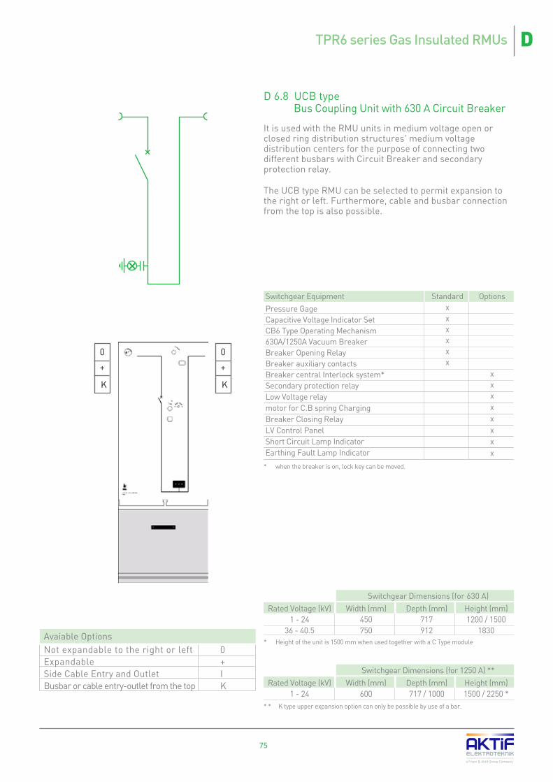
75
a Friem & Aktif Group Company
D 6.8 UCB type Bus Coupling Unit with 630 A Circuit Breaker
It is used with the RMU units in medium voltage open or closed ring distribution structures' medium voltage distribution centers for the purpose of connecting two different busbars with Circuit Breaker and secondary protection relay.
The UCB type RMU can be selected to permit expansion to the right or left. Furthermore, cable and busbar connection from the top is also possible.
0
+
K
0
+
K
Pressure GageCapacitive Voltage Indicator SetCB6 Type Operating Mechanism630A/1250A Vacuum BreakerBreaker Opening RelayBreaker auxiliary contactsBreaker central Interlock system*Secondary protection relayLow Voltage relaymotor for C.B spring ChargingBreaker Closing RelayLV Control PanelShort Circuit Lamp Indicator Earthing Fault Lamp Indicator
Options
xxxxxxxx
Switchgear Equipment Standardxxxxxx
* when the breaker is on, lock key can be moved.
DTPR6 series Gas Insulated RMUs
Avaiable Options0+IK
Not expandable to the right or leftExpandableSide Cable Entry and OutletBusbar or cable entry-outlet from the top
* Height of the unit is 1500 mm when used together with a C Type module
Switchgear Dimensions (for 630 A)
Rated Voltage (kV)1 - 24
36 - 40.5
Width (mm)450750
Height (mm)1200 / 1500
1830
Depth (mm)717912
* * K type upper expansion option can only be possible by use of a bar.
Switchgear Dimensions (for 1250 A) **
Rated Voltage (kV)1 - 24
Width (mm)600
Height (mm)1500 / 2250 *
Depth (mm)717 / 1000

76
a Friem & Aktif Group Company
D 6.9 Q type Measuring Unit with Circuit Breaker (for 36 kV)
It is used with the RMU units in medium voltage open or closed ring distribution structures' medium voltage distribution centers for the purpose of measurement of electricity consumption at the busbar by entering to the busbar by a cable or another busbar.
A cable or busbar connection to a Q Type RMU from the top is possible.
* when the Disconnector is off and breaker is on, lock key can be moved.
K
Pressure GageCapacitive Voltage Indicator SetLT + TCB Type Operating Mechanism630A/1250A Vacuum BreakerBreaker Opening RelayBreaker auxiliary contactsBreaker central Interlock system*Disconnector auxiliary contactsEarthing Disconnector auxiliary contactsDisconnector Interlock (Open)Earthing Disconnector Interlock (Open)Earthing Disconnector Interlock (Close)Disconnector Key LockEarthing Disconnector Key LockSecondary protection relayLow Voltage relaymotor for Circuit Breaker spring ChargingBreaker Closing RelayLV Control PanelShort Circuit LampEarthing Fault Lamp IndicatorCurrent Transformer Cable ConnectionCurrent TransformerVoltage Transformer
Options
xxxxxxxxxxxxxxxxx
Switchgear Equipment Standardxxxxxxx
D TPR6 series Gas Insulated RMUs
Avaiable Options0+IK
Not expandable to the right or leftExpandableSide Cable Entry and OutletBusbar or cable entry-outlet from the top
* Except the upper bar section
Switchgear Dimensions (for 630 A)
Rated Voltage (kV)36
Width (mm)1000
Height (mm)1830 *
Depth (mm)1150

D 6.10 M type Measuring Unit
It is used with the RMU units in medium voltage open or closed ring distribution structures' medium voltage distribution centers for the purpose of measurement of electricity consumption at the busbar.
The M type RMU can be selected to permit expansion to the right or left. Busbar connection to a M Type RMU from the top is possible.
77
a Friem & Aktif Group Company
0
+
K
Connection BushingsCurrent Transformer Mounting plateVoltage Transformer Mounting plate1 or 2 piece Electric Connection KitNo 2-3 Current TransformerNo 2-3 Voltage TransformerLV Control PanelFuse and Fuse-Box
Options
xxxxx
Switchgear Equipment Standardxxx
0
+
K
DTPR6 series Gas Insulated RMUs
Avaiable Options0+IK
Not expandable to the right or leftExpandableSide Cable Entry and OutletBusbar or cable entry-outlet from the top
Switchgear Dimensions (for 630A)
Rated Voltage (kV)1 - 24
36 - 40.5
Width (mm)850
1100
Height (mm)12001830
Depth (mm)717
1150

78
a Friem & Aktif Group Company
D 7 Sample Busbar Design with RMU
Sample 1 :
A medium voltage busbar with 1 Incoming and 3 Outgoings, not expanding to the right or left, consisting of L type Incoming unit with a load separator (not expandable to the right) where busbar Incoming is made and 2 L type Outgoing units with a F type unit (no expandable to the right).
With the notation of “0 L”, it is stated that the far most left hand side L type unit cannot be expanded to the left and similarly with “F 0”, the far right hand side F type Switchgears will not expand to the right.
Sample 2 :
A medium voltage busbar with 1 Incoming and 3 Outgoings, expandable to the right and left, consisting of L type Incoming unit with load separator (expendable to the left) where busbar Incoming is made and 2 F type unit (expendable to the right).
With the notation of “+ L”, it is stated that the far most left hand side L type unit can be expanded to the left and similarly with “F +”, the far right hand side F type Switchgears can be expanded to the right.
Sample 3 :
A circuit breaker protection solution is derived with an F type unit that could not expand o the right hand side, by direct cable connection module for energy feeding.
With the notation of “F O”, it is stated that the left hand side F type unit cannot be expanded.
D TPR6 series Gas Insulated RMUs

79
a Friem & Aktif Group Company
Sample 4 :
Busbar Incoming is performed with L type Incoming unit with load separator (not expandable to the left) and Outgoing is realized with 1 L type unit (expandable to the right) and in addition, one M unit added to the busbar. It is a busbar solution by addition of an F unit that is extendable to the left on the right hand side, and addition of 2 F type not extendable units to the left hand side of the busbar.
With the notation of “0 L”, it is stated that the far most left hand side L type unit cannot be expanded to the left and similarly with “L +”, the far right hand side L type Switchgears can be expanded to the right and with “+ F” notation, it is shown that the additional unit on the left can be added to the medium voltage busbar from the far right hand side and with “F 0” notation it is indicated that the far right hand side Switchgears can be expanded from its right hand side.
Sample 5 :
This is a sample application of connecting three medium voltage busbar composed of two units are connected with a cable or busbar overhead.
In the first busbar “0 L” coded unit describes that the unit with a load separator cannot be expanded to the left and the unit with “L K” is an Outgoing unit that can be connected with a cable or busbar.
The units with the notation of “0 L” on the second and third busbars indicates these unites that are protected by load separator circuit breaker are not expandable to the left, and “F K” notation shows that these load separator circuit breaker protected transformers can have Outgoing with cable or a busbar from the top.
Sample 6 :
In this sample, the energy has been transferred to a busbar by an L unit which has a load separator and is not expandable to the right and one Outgoing is secured by an L unit which does not expand to the right and has a load separator as well as two Outgoings by an F unit that has a load separator circuit breaker and does not expand to the right.
In this sample, it is noted that the unit with “0 L” code cannot expand to the left and has Incoming-Outgoing with a load separator, “L” denotes Incoming-Outgoing with load separator with no expandability either to the right or left, whereas the unit that has "F 0" indicates that it is a Incoming-Outgoing unit with circuit breaker and load separator and it does not expand to the right. The unit with an “M” code is a measurement unit that does not expand to the right or left and the Incoming or Outgoing is only performed by a cable.
DTPR6 series Gas Insulated RMUs
E 1 Switching Equipment E 1.1 Circuit Breakers E 1.1.1 SVC Series Vacuum Circuit Breakers E 1.1.2 SION/3AH (Siemens) Vacuum Circuit Breakers E 1.1.3 EVOLIS (Schneider) Vacuum Circuit Breakers E 1.1.4 SF1 (Schneider) SF6 Gas Circuit Breakers E 1.1.5 SF2 (Schneider) SF6 Gas Circuit Breakers E 1.2 Vacuum Contactors E 1.3 LBS and DisconnectorsE 2 Protection Devices E 2.1 Relays E 2.1.1 M series Digital Protection Relays E 2.1.2 MC series Digital Protection Relays E 2.1.3 ULTRA series Protection Relays E 2.1.4 DTVA series Distance Protection Relays E 2.1.5 ANSI codes Relay Application Table E 2.1.6 Relay Management Software E 2.2 Circuit BreakersE 3 Measuring Devices E 3.1 Capacitive Voltage Indicators E 3.2 Analyzers E 3.2.1 NQM series Energy Analyzers E 3.2.2 NPM series Power Analyzer E 3.2.2 Energy Management Software E 3.3 Power Quality Recorders E 3.3.1 2400d series Power Quality Recorder E 3.3.2 2400ip series Power Quality Recorder E 3.3.3 2400R series Power Quality Recorder E 3.3.4 2400duo series Power Quality Recorder E 3.3.5 2400i series Power Quality Recorder E 3.4 Electricity Meters E 3.4.1 MT860 Electricity meter for Transmission & Production E 3.4.2 MT830 Electricity meter for Distribution & Industry E 3.4.3 MT372 Electricity Meter for Small Size Commercial Subscribers E 3.4.4 MT173 Electricity Meter for Small Size Commercial SubscribersE 4 Measuring Transformers E 4.1 Current Transformers E 4.2 Voltage Transformers
80
8282828484848485858686868686868788888989909090909191919191919292929292939393
AuxiliaryEquipment

82
1. Label2. Interlock arm3. Auxiliary carrying support4. Contacts5. Mechanism box6. Push mechanism7. Busbar shell8. Tube protector9. 48 pin plug
7,2kV200320775700640
12kV200320775700640
17,5kV200320775700640
24kV200320775700640
36kV350455
1150930960
40,5kV350455
1150930960
3,6kV200320775700640
ABCDE
1
2
3
A
B
C
D D
E
4 5
6
7
9
8
E 1 Switching Equipment
E 1.1 Circuit Breakers
Aktif Elektroteknik use followings Vacuum or SF6 gas insulated circuit breakers in air insulated medium voltage Switchgears in conformity with IEC 62271-100 standards.
1.1.1 SVC (Aktif) Vacuum Circuit Breaker (are manufactured up to the capacities of 40.5 kV, 3150A, 31.5 kA and are used in the production).1.1.2 SION/3AH (Siemens) Vacuum Circuit Breakers1.1.3 EVOLIS (Schneider) Vacuum Circuit Breakers1.1.4 SF1 type (Schneider) SF6 gas insulated Circuit Breakers1.1.5 SF2 type (Schneider) SF6 gas insulated Circuit Breakers
E 1.1.1 SVC series Vacuum Breakers
SVC series Vacuum Circuit breakers are designed by Aktif and their patent is obtained. In this manner the Switchgears and breakers are supplied from one source.
Three pieces excellent insulated high quality Vacuum interrupters are used In SVC series Vacuum Circuit breakers as placed inside a special casing.
a Friem & Aktif Group Company
Auxiliary Equipment Switching EquipmentE 1

83
The SVC units have compact structures and provide sturdy, safe mechanical operation.
SVC series Vacuum Circuit Breakers are also designed as drawer type.
The electrical arc is insulated in the vacuum environment and extinguished within the vacuum. When an internal arc formed, the extinguishing process takes place within the vacuum tube; hence there would not be any release to the outside. The vacuum tube does not need any maintenance. Due to its general characteristics its contact structure would not be deteriorated. Therefore it can be used more efficiently when compared to similar products.
E 1.1.1.1 Application Areas
SVC units are used in the following application areas:
� Overhead transmission lines� Distribution and transformer centers� Cables� Transformers� Motors� Generators� Capacitor banks
E 1.1.1.2 Advantages
� Fulfilling committed energy targets � Excellent performance� Excellent Endurance� Long operation life� Low maintenance cost (fast and economic maintenance)
Technical Specifications:
UnitkVkVkVHzA
kA/3skA
Amsmsmsop.VC°
7,22060
122875
17,53895
2450
125
3670
170
Description Values
50 / 60630 - 1250 - 1600 - 2000 - 2500 - 3150
O - 0,3s - CO - 180s - CO400
35 - 6040 - 50
6020.000
DC: 24, 110 / AC: 220-5°...+40°
Rated Voltage (Ur)Power frequencywithstand VoltageRated Frequency (Fr)Rated Current (Ir)Rated short time withstand current(lk)Rated short time withstand current(lp)Operational sequenceCapacitive load switching current (lc)Closing timeOpening timeProcess timeMechanical LifeRated control circuit voltageOperational temperature
1 minute high frequency withstand voltage (Ud)Lightning impulse withstand voltage (Up)
3,61040
40,585
190
16 - 25 - 31,540 - 63 - 80
16 - 2540 - 63
a Friem & Aktif Group Company
Auxiliary Equipment Switching Equipment E 1

E 1.1.2 SION/3AH (Siemens) Vacuum Circuit Breaker
The vacuum breakers are subjected to routine tests during production and these tests are harder than the requirements of the standards.
� Current measurement data flow� Decisive measurement data� Low power loss� Long term thermal stability� The vacuum circuit breakers do not need maintenance Under normal operational conditions, 10000 opening and closing as per IEC 60694 and VDE 0670 part 1000� The performance remains within the limits even in frequent usage after long term stand-by periods� Environmentally sensitive.
E 1.1.3 EVOLIS (Schneider) Vacuum Circuit Breaker
Evolis vacuum breakers have 3 poles and they are for internal use. This kind of circuit breaker is used for the switching and protection purposes in the industry, public sector and energy distribution.
These types of breakers are suitable for LSC2B type metal partitioned metal clad sells.
Rated Voltage : up to 24 kV Rated Current : up to 2500 A Short Circuit switching Current : up to 40 kA
E 1.1.4 SF1 type (Schneider) SF6 Gas insulated Circuit Breaker
SF1 with 3 poles is for medium voltage internal usage. Between 1 kV and 40.5 kV, this kind of circuit breaker is used for the switching and protection purposes in the industry, public sector and commercial distribution. The SF1 breaker equipped with automated compression technique and uses SF6 gas during current cutting phase. There are 3 types of SF1:
� Horizontal type suitable for metal enclosed LSC2A Switchgears
Rated Voltage : up to 40.5 kV Rated Current : up to 1250 A Short Circuit switching Current : up to 25 kA
E 1.1.5 SF2 type (Schneider) SF6 Gas insulated Circuit Breaker
SF2 with 3 poles is for medium voltage internal usage. Between 24 kV and 38 kV, this kind of circuit breaker is used for the switching and protection purposes in the industry, public sector and commercial energy distribution. These types of breakers are suitable for LSC2B metal clad Switchgears.
Rated Voltage : up to 40.5 kV Rated Current : up to 2500 A Short Circuit switching Current : up to 31.5 kA
84
a Friem & Aktif Group Company
Auxiliary Equipment Switching EquipmentE 1

85
E 1.2 Vacuum Contactors
The vacuum contactors have 3 poles and have cycle capacity of over 1 million in the medium voltage facilities with their high electromagnetic characteristics.
The vacuum contactors are also performed for alternative current facilities for the below given purposes:
� Motor start-up� Switching of transformers� Switching of reactors� Switching of big resistive loads similar to those in electric furnaces� Switching of capacitor banks
E 1.3 Load Break Switches
SLB series Load Break Switches used are in conformanity with IEC 60295-1 and 62271-102 standards and load break switches are able to switch the circuit on load. The rated current is up to 630 A and the short circuit withstand is up to 20 kA.
The Load Break Switch has SF6 gas and it switches on load. It has 3 poles and 3 modes (open - close - earthed). The Earthing Disconnector is located in Load Break Switch structure.
E 1.4 Disconnectors
E 1.4.1 SF6 gas insulated Disconnectors
SGD series SF6 gas insulated Disconnectors are used in conformity with IEC 60295-1 and 62271-102 standards. The rated current is up to 1250 A and the short circuit withstand is up to 25 kA.
Furthermore, it has SF6 gas and it has opening and closing feature without load. It has 3 poles and 3 modes (open - close - earthed). The Earthing Disconnector is located in Load Break Switch structure.
E 1.4.2 Air insulated Rotary Switches
SRS series Air Insulated Rotary Switches have rated current of up o 1250 A and short circuit withstand current of up to 25 kV and are used in Metal Enclosed Switchgears.
E 1.5 Earthing Disconnectors
SES series earthing switches are manufactured and produced with 3 second withstand up to 31.5 kA and 1 second withstand up to 50 kA.
In close position In open position Grounding
a Friem & Aktif Group Company
Auxiliary Equipment Switching Equipment E 1

86
a Friem & Aktif Group Company
E 2 Protection Devices
E 2.1 Relays
Microelettrica Scientifica secondary protection relays are used in our products. These relays are digital and able to provide protection in different applications and functions. These relays have Modbus RTU, IEC 60870-103 or IEC 61850 communication protocols; are classified as M series, MC series, Ultra series and DTVA series. The protection functions that can be done with these relays are;� Current & Voltage protection� Feeder, Line and Busbar protection� Transformer protection� Motor and Generator protection � Capacitor feeder protectionIn addition to these protection functions, trip and event recording can also be obtained. These relays provide easy to use feature with their draw-out execution. Relays can communicate with MSCom2, Actwin RM and any Scada software.
E 2.1.1 M series
� These relays are microprocessor based and are used in high and medium voltage systems.� They have Modbus RTU communication protocol and R485 serial communication port at the back.
E 2.1.2 MC series
� Different protection features are combined in these relays due to its compact structure. � They have one R485 serial communication port at the back and there is one RS232 serial communication port on the front panel.
E 2.1.3 ULTRA series
� These relays can be used in any application in transmission, distribution and industrial plants.� It combines protection, measurement and control features. � In addition to R485 serial communication port at the back and one RS232 serial communication port on the front panel, Modbus RTU/IEC60870-5-103/IEC61850/TCP-IP communication protocols are also presented.
E 2.1.4 DTVA series
� These relays make distance protection in 3 phase, phase to phase and phase to ground faults. � These relays are distance protection relays that have auto reclosing function.� The communication can be done by RS232 from the front panel and by fiber optic connection from the rear of the equipment.� These relays have the functions of remote testing by a computer,collecting the measured values and setting.
Auxiliary Equipment Protection DevicesE 2

87
a Friem & Aktif Group Company
E 2.1.5 ANSI codes Application Tables
Note: This table is prepared by taking into consideration of frequently used relays. There are a lot of relays applicablefor protection functions that are not listed here being used. Please ask for a copy of detailed product catalogue for other relays and protection functions that are not listed in this table.
Auxiliary Equipment Protection Devices E 2
12/142124252727/5927/59d3237404646N47484950/5150/51N50/51V51BF51LR555959Uo60FL6464S64SEF666767N6874787981868787/8587B87N90df/dtdv/dtI2tOsi2xIn2-set
Sekonder Koruma Röleleri Genel Uygulama Tablosu
DL
MR
DM
30-S
DM
33D
TMR
DTM
R-3
DTV
A-E
PF
MR
GM
RIM
30-A
BIM
30-A
PIM
30-B
00IM
30-B
YIM
30-C
IM30
-DIM
30-D
TIM
30-G
IM30
-SA
IM30
-SR
IM30
-TM
C1V
MC
3VM
C20
MC
30M
C30
-RM
C30
-RG
MC
MM
D32
-GM
D32
-TM
D33
-TM
FP
MG
30M
MR
MM
30M
M30
-DM
M30
-WM
TR33
MW
33M
-HIB
3M
-LIB
3R
IA12
3S
CM
21S
PM
21U
M30
-AU
FD
14U
FD
34
Speed ControlDistance protection / Under impedanceVolts per HerzSynchronization and/or synchrocheckUnder Voltage (AC)Under/over Voltage (AC)Under/over voltage of positive sequenceDirectional PowerUnder current or under powerLoss of fieldReverse phase or phase balanced currentUnbalanced protection for capacitorsPhase sequence or phase balance voltageControl of motor starting sequenceThermal protection for machine or trafoInstantaneous / time delayed over currentInstantaneous / time delayed earth faultVoltage restrained over currentBreaker failure protectionLocked rotor protectionPower factor Over voltage (AC)Zero sequence over voltageFuse failureGround fault protection (insulation)Machine stator ground faultSensitive earth fault protectionControl of motor starting number AC directional over current relayDirectional earth fault relayBlocking outputTrip circuit supervisionPhase angle or out of step protectionReclosingFrequencyLock-outDifferential protectionPilot cable differential protectionBusbar differential protectionDifferantial earth fault currentRegulating controlFrequency rate of changeVoltage rate of changeBreaker interruption energyOscillographic waveform capturing Automatic threshold doubling on inrushDouble setting
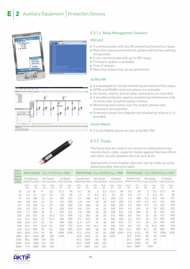
88
a Friem & Aktif Group Company
Trans-former Rated Power(KVA)
Rated Voltage U1N= 17,5 kV U2N = 400V
Transformer Rated Current
prim.(A)
sec.(A)
MV Rated Fuse Currentmin.(A)
max.(A)
LV Rated Fuse Currentmin.(A)
max.(A)
U1N= 20/24 kV U2N = 400V
Transformer Rated Current
prim.(A)
sec.(A)
MV Rated Fuse Currentmin.(A)
max.(A)
LV Rated Fuse Current
min.(A)
max.(A)
6,36,36,3101620202525405063638080
100125
46,36,310101616202025
31,540506380
100125
3672
108144180231289361455577722909
11551443180423092887
0,71,42,22,93,64,65,87,29,1
11,514,418,223,128,936,146,257,7
31,563
100125160200250315400500630800
10001200
---
4080
125160200250315400500630720900
1200----
0,51,01,41,92,43,13,84,86,17,79,6
12,115,419,224,130,838,5
3672
108144180231289361455577722909
11551443180423092887
24
6,36,36,3101016161625
31,540405063
6,36,36,36,3101616202525
31,54050506380
2x50
31,56310012516020025031540050063080010001200---
4080
125160200250315400500630720900
1200----
Transformer Rated Currentprim.
(A)sec.(A)
MV Rated Fuse Currentmin.(A)
max.(A)
LV Rated Fuse Currentmin.(A)
max.(A)
U1N= 30/36 kV U2N = 400V
255075
100125160200250315400500630800
1000125016002000
1,01,92,93,84,86,27,79,6
12,115,419,224,230,838,548,161,677,0
367210814418023128936145557772290911551443180423092887
46,3101016162025252531,5406380100125160
6,310101620252531,531,540506380100100125160
31,563
100125160200250315400500630800
10001200
---
4080
125160200250315400500630720900
1200----
Rated Voltage Rated Voltage
E 2.1.6 Relay Management Software
MSCom2
� It communicates with any Microelettrica Scientifica relays. � Real time measurement and all system and function settings are possible. � It can communicate with up to 250 relays.� Firmware update is available.� Free of charge.� Real time measuring can be performed.
ActWin RM
� It is developed for remote monitoring and control of the relays. � GPRS and RS485 communications are available.� All events, alarms and all other operations are recorded.� It provides protection against unauthorized interference with its three level of authorization scheme. � Monitoring and control over the mobile phones and computers are available. � Drawing a single line diagram and displaying relay on it, is provided.
Actwin Mobile
� It is the Mobile phone version of ActWin RM.
E 2.2 Fuses
The fuses that are used in our products safely protect the transformers, cable, capacitor banks against thermal effects and short circuits between the 6 kV and 36 kV.
Appropriate circuit breaker selection can be made by using below provided reference table.
Auxiliary Equipment Protection DevicesE 2
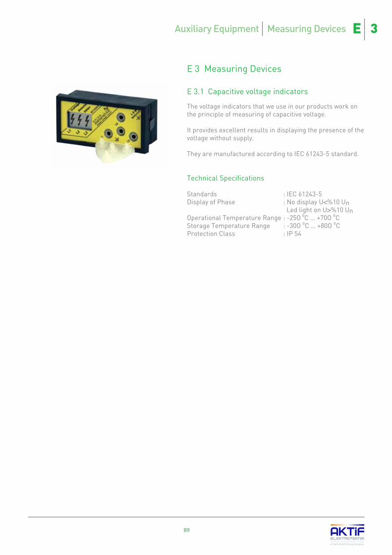
E 3 Measuring Devices
E 3.1 Capacitive voltage indicators
The voltage indicators that we use in our products work on the principle of measuring of capacitive voltage.
It provides excellent results in displaying the presence of the voltage without supply.
They are manufactured according to IEC 61243-5 standard.
Technical Specifications
Standards : IEC 61243-5Display of Phase : No display U<%10 Un Led light on U>%10 Un Operational Temperature Range : -25O oC … +70O oCStorage Temperature Range : -30O oC … +80O oCProtection Class : IP 54
89
a Friem & Aktif Group Company
Auxiliary Equipment Measuring Devices E 3

90
E 3.2 Power & Energy Analyzers
Analyzers combine voltmeter, cosphimeter, wattmeter, var-meter and frequency-meter into single equipment. Therefore, it is possible to make savings from space, cable and cost of equipment.
The data read can be transferred to SCADA or energy Management Software on a computer via communication ports that on the equipment. Since this data is kept in the data base of the equipment, it provides simplicity in fault determination. Furthermore consumption figures for the past periods can be obtained hence planning towards future can be made more consistently.
Due to digital outputs provided by the equipment it has became indispensible part of SCADA systems. Transducer usage becomes unnecessary by the help of some models which have analog outputs.
Due to these features, the analyzers become essential part of any management or automation system.
E 3.2.1 NQM series Energy Analyzers
� Large 128 x 128 graphic LCD� Embedded memory for measurements records (with extendable memory)� Programmable digital outputs (maximum 6)� Digital inputs may be used as a counter (for gas and water meters) and position monitoring (maximum 8)� Programmable analog outputs (maximum 4)� RS232 and RS485 communication ports� Current and voltage waveform display on the screen� Harmonic analysis� Faulty connection warning
E 3.2.2 NPM series Power Analyzer
� RS485 communication port� 4 LED screen that can be read remotely� Display of more than 30 electrical parameter
E 3.2.3 Energy Management Software
Actwin Energy Management Software reads all energy parameters of Asset Power Analyzers and digital Electricity Meters and records the data with time labels. It supports various communication interfaces as well as communication protocols.
With different reporting and monitoring screens, various reports and invoices can be created by the parameters recorded and can be viewed in different formats in real time.
The most important feature of the software is that the data reading is possible from multiple ports simultaneously and this increases communication speed to a maximum level. In this manner, it is possible to obtain more reading and create much more detailed reports.
a Friem & Aktif Group Company
Auxiliary Equipment Measuring Devices E 3

91
a Friem & Aktif Group Company
E 3.3 Power Quality Recorders
Energy quality recorders are the necessary equipment for analyzing the quality of electric networks according to related standards (EN 50160, IEC 6100-4-7). The various electrical parameters such as flickers, harmonics, inter-harmonics, symmetric components, instability and energy can be monitored simultaneously.
According to EN 50160, IEC 61000-3-6/7 standards, all statistical data relating to quality of the energy of the distribution and transmission systems including voltage sag, swell and interruptions and so on are recorded by IEC 61000-4-30 class A and detailed reporting in conformity with the standards are made.
E 3.3.1 2400d Series Power Quality Recorder
� DIN rail type, compact structure, suitable for placing in a panel. � Without an external connection, assembled solutions� RS232 and USB connection� GPS and pulse synchronization � Screwed input terminal blocks � Ethernet and website interface� PSTN and GSM/GPRS modem� DC insulated 4 current and 4 voltage measurement inputs in 2444d model� Only 4 voltage measurement inputs in 2440d model
E 3.3.2 2400ip Series Power Quality Recorder
� Suitable design for heavy conditions� IP 65 protection class against water, dust and impacts� 4 voltage and 4 current measurement inputs� Water proof connections� Wall mounted type structure and flush mounting
E 3.3.3 2400R Series Power Quality Recorder
� The best protection and safety level in its own class� Galvanized insulated 4 voltage and 4 current measurement inputs� Screw type connections to the terminal blocks that provides maximum level of safety� Strengthened battery for 3 hours of operation
E 3.3.4 2400duo Series Power Quality Recorder
� Measuring two transformers' parameters simultaneously at transmission and distribution substations or in industrial plants� DC insulated 8 current and 8 voltage measurement inputs� Screw type connections to the terminal blocks that provides maximum level of safety
E 3.3.5 2400i Series Power Quality Recorder
� 4 current and 4 voltage measurement input� High speed communication
Auxiliary Equipment Measuring Devices E 3

92
E 3.4 Electricity Meters
Unless otherwise required, static electric meters are used in our products and meters with appropriate features and certifications are chosen for different applications.
E 3.4.1 MT860 Electricity Meter with High Accuracy for Transmission and Production Plants
� Class 0.2S active energy measurement accuracy� Active, reactive and apparent energy/demand measurement� Modular communication and input/output options� Sag/swell and interruption measurements� Leakage detection and recording function� Due to the optic probe, there is no need to energy for reading� Various communication alternatives (RS485, GSM/GPRS, Ethernet)
E 3.4.2 MT830 Electricity Meter for Distribution and Industrial plants
� Class 0.5s active energy measurement accuracy� Active, reactive and apparent energy/demand measurement� In conformity with the EPDK technical specifications� Energy interruption counter� Harmonic component analysis� Leakage detection and recording function� Various communication alternatives (RS485, GSM/GPRS, Ethernet)
E 3.4.3 MT 372 Electricity Meter for Small Size Commercial Subscribers
� Class 1 active energy measurement accuracy� Active, reactive and apparent energy/demand measurement� Suitable for pre-paid subscriptions with internal cut-off device � Internal GPRS modem option� Possibility of reading water and gas meters with MBus output� Various communication alternatives (RS485, GSM/GPRS, Ethernet, MBus)
E 3.4.4 MT173 Electricity Meter for Small Size Commercial Subscribers
� Class 1 active energy measurement accuracy� Active, reactive and apparent energy/demand measurement� Network/generator tariffs� Different tariffs during the day (Day, night, peak time)� RS485 communication port
a Friem & Aktif Group Company
Auxiliary Equipments Measuring Devices E 3

93
E 4 Measuring transformers
We use, depending on the requirement, either conventional type measurement transformers in conformity with IEC 60044-1 and IEC 60044-2 or Rogowski type cast resin measurement transformers in conformity with IEC 60044-8.
E 4.1 Current transformers
� Current/Voltage slope is extremely linear and does not get saturated� Can work in many different frequencies� Since it does not have iron core, fast current change and transient response is very well.� Decreases the interaction due to magnetic field.
Rogowski and Conventional type of current transformers are used in SME series switchgears.
� Internal Type - with supports /bushings� Internal Type - with capacitive layers� External Type
Basic Specifications
� Operational voltage : up to 40.5 kV� Withstand voltage : up to 85 kV� Short period testing voltage (1.2/50ºs) : up to 185 kV � Rated frequency : 50 / 60 Hz� Rated primer current : up to 4000 A� Secondary coils : 1 / 5 A � Short period thermal withstand current (1s) : up to 1000 In� Insulation Class : E
E 4.2 Voltage transformers
The cast resin coated conventional voltage transformers used in our products are as follow:
� Internal type single pole insulated with circuit breaker� Internal type single pole insulated without circuit breaker� Internal type double pole insulated
Basic Specifications
� Operational voltage : up to 40.5 kV� Withstand voltage : up to 85 kV� Short period testing voltage (1.2/50ºs) : up to 185 kV � Rated frequency : 50 / 60 Hz� Rated primer current : up to 40.5/√3 kV� Secondary Voltage : 100/√3 V, 110/√3 V, 120/√3 V � Class : 0,2 / 0,5 / 1� Nominal gerilim faktörü : 1,9 � Insulation Class : E
a Friem & Aktif Group Company
Auxiliary Equipments Measuring Transformers E 4


Headquarter MerkezBayraktar Blv. Şehit sk. No: 5 Aktif Plaza 34775 Ümraniye Istanbul - TürkiyeTe l : +90 216 314 93 20Fax : +90 216 314 93 60
Factory Fabrika
Akşemsettin mah. Çatalca sk. No:113 06930 Sincan Ankara - TürkiyeTe l : +90 312 269 46 02 Fax : +90 312 269 45 01
Orta Gerilim Hücreler
Anahtarlama Ürünleri
Köşk Tipi Trafo Merkezleri
Mobil Trafo Merkezleri
Dağıtım Trafoları
Dirençler
Enerji Kalitesi Çözümleri
Tıbbi Güç Dağıtım Sistemleri
Kondasatör ve Reaktörler
Sayaç Otomasyonu ve Faturalama
Ölçme ve Yönetim Sistemleri
Sekonder Koruma Röleleri
Kaçak Akım Röleler
Yüksek Güç Dönüştürücüleri ve Redresörler
Güneş Enerjisi Çözümleri
Cer Gücü Dağıtım Merkezi
Depo Alanı Çözümleri
Araçüstü Ekipmanlar
Eubiq Flexible Power Outlet SystemEubiq Esnek Fiş - Priz Sistemleri
White…Color of the beginning…White, color of the purity, honesty and clarity…
Color of the stability and continuity, trust and quality…
Since 2010, we decided to apply white color which symbolizes all of these values to all of our products.
Beyaz...Başlangıcın rengi...Saflığın, dürüstlüğün, aydınlığın rengi beyaz...
İstikrar ve devamlılığın, güvenin, kalitenin rengi...
2010 yılından itibaren, tüm bu değerleri taşıyan beyazı, ürünlerimizin temel rengi olarak benimsedik ve uyguladık.
a Friem & Aktif Group Company
Doc
. Nr.
A
ET-S
W 1
425/
C.E
ng O
win
g to
per
iodi
cal i
mpr
ovem
ents
of o
ur p
rodu
cts t
he su
pplie
d pr
oduc
ts m
ay d
iffer
in so
me
deta
ils fr
om th
e da
ta st
ated
in th
e pr
ospe
ctus
mat
eria
l. Pu
blish
ed b
y Ak
tif E
lekt
rote
knik
A.S
. Da
ta su
bjec
t to
alte
ratio
n w
ithou
t noti
ce.
De
sign
& C
reati
on: A
ktif G
roup
/ P
hoto
s: A
ktif G
roup
- St
ock.
xchn
g &
Shu
tters
tock