metal clad type switchgeardt it h · • mechanical outside door interlock ensures safe maintenance...
TRANSCRIPT
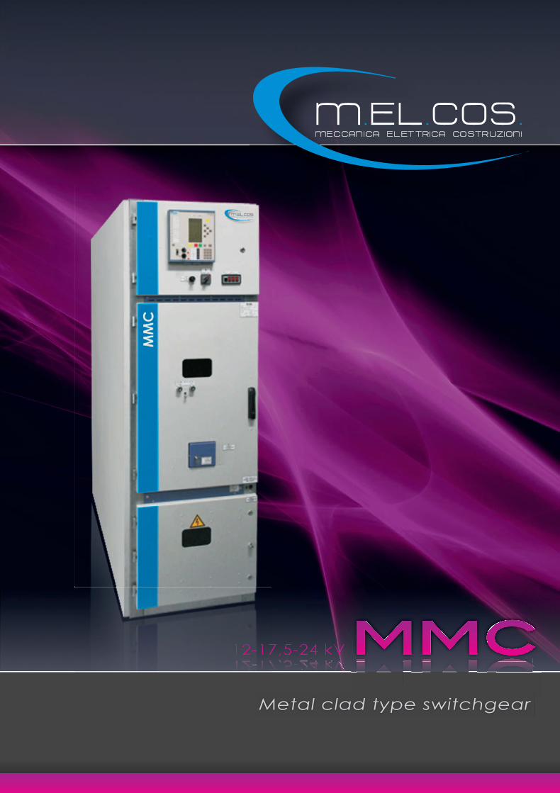
Metal clad type switchgeard t it h
COMPANY PROFILE
M.EL.COS. was founded in Arezzo (Italy) in 1983 by
ex-employees from Costruzioni Elettromeccaniche
Banchelli, leader company in its field, today can boast
about high professional competence and about
modern and updated technologies in the electrome-
chanical field. Since the beginning M.EL.COS. focused
on the production of Medium Voltage switchgears,
steel structures, Low Voltage switchgears and outdoor
cabinets in rolled section and nowadays the company
products are well-known and appreciated. Coopera-
tion is the key action of the company success, in fact
only with mutual efforts of project, production and mar-
keting activities, it is possible to satisfy the customer
needs strictly related to high volumes, quality, low-
costs, and on-time deliveries. The development of the
organization of production and managing activities
underlines the will to follow the innovation trend and,
together with the qualification of personnel, allows the
company to achieve high level goals. One of these
goals is the quality certification VISION 2000 concerning
the products and services. M.EL.COS. is now also able
to match, in a very flexible way, standard product lines
with special executions in order to better fulfill every
single request from the customers.
1
Indice / Index
2Main characteristics
3Economical design
5Technical data
4Presentation
6Design
7Typical units
8Busbar compartment
9Cable compartment
11Circuit-breaker compartment
10Low voltage compartment
14Packaging - Handling - Storage
15Unpacking and installation of the equipment
18Operating accessories
• Make-type earthing switch• Operation of all switching devices with front door closed, one side maitenance• Complete air insulation of all switchboard live parts• IP3X degree of protection on the external housing• Constructed to withstand the overpressures caused by the internal arc• Busbar segregation shutters activated automatically by circuit breaker movement inside the compartment• Construction of three high voltage compartments with draw-out circuit breakers• Type tested according IEC62271-200• Designed for high power regional substation switchgears• Make-type earthing switch• One side maitenance• Operation of all switching devices with front door closed• Complete air insulation of all switchboard live parts• IP41 degree of protection on the external housing• Constructed to withstand the overpressures caused by the internal arc up to 50kA/1s• Mechanical outside door interlock ensures safe maintenance
2
• MaMakeke-ttypypee eaeartrthihingng s swiwitctchh•• OpOpereratatioionn ofof a allll s swiwitctchihingng d deveviciceses w witithh frfronontt dodooror c clolosesedd, o onene s sididee mamaititenenanancece• CCompllete aiir i ins lulatiion fof allll s iwitchbhboa drd l liive partspp pp• IPIP3X3X ddegegrereee ofof pprorotetectctioionn onon tthehe eextxterernanall hohoususiningg
Main characteristics
Fully metal-clad, type tested according IEC
Cubicles must be operating under normal conditions in accordance with the IEC60694 standard, but the ambient air temperature could be comprised till - 10° C (critical permissible ambient air temperature - 20° C). Cubicles can be used up to an altitude of 1000 m. Beyond that (altitude up to 3000 m) it's necessary to take into account of a decrease in the dielectric strength (for example: on purpose to install cubicles in 10 kV network, when altitude is 2500 m, it's necessary to specify insulation level for 17,5 kV in an order). In cubicle operation environment must be no dust particles, fumes or smoke, corrosive or flammable gases, vapors or salts. Cubicles have IP4X degree of protection for current up to 1250 A ant IP3X - for current above 1250 A in accordance with the IEC 60529 standard. IP41 degree of protection is available by special order. Cubicles are manufactured in accordance with the factory standard _ST 4474977.01:1996 and complies with IEC 62271-200 standard. When commissioning and operating switch-gear equipment under normal conditions, the general electrical safety instructions (gloves, insulating stool, etc.), as well as operation handling instructions should be respected. The sequent of disregarding given instruction is the loss of warranty repair.
Technical description

The torsionally rigid housings of the cubicles are made of 2.0… 3.0 mm thickness galvanizedsteel sheets folded at the edges and bolted together. With the selection of high quality materials, special surface treatment and powder painting, the conditions for high impact and corrosion resistance are fulfilled. Special labyrinth construction of panel's side elements and doors ensure personnel safety against arc faults.Switchboards can be fixed to the special foundation, using anchoring bolts above cable ducts.
• Low meintenance vacuum circuit-breakers from AREVA, Germany• Easy circuit-breaker replacement due to craw-out type circuit-breaker units.• The torsionally rigid housing with very high corrosion resistance• Separate mechanism for upper and lower shutters.• Simple inspection and maintenance, thanks to easy access to the apparatus in the various compartments through doors or easily removable panels and to the possibility of isolating and removing the circuit breaker.• Flexibility of engineering is based on a truly modular concept with many product variations, configurations and options. Bolted construction allows for faster replacement and modification in the field. All of these features lead to reduced cost of ownership and risk.• Precision fabrication equipment and advanced construction techniques result in high quality, properly aligned modules that support efficent field installation and commisioning, and provide consistent interchangeability of drawout elements with common ratings. Modern bolted construction also greatly reduces the down time and costs associated with system changes and expansions.
Cubicle structure
Economical design
3

Presentation
4
MMC-xx xx-xx cubicles are used in indoor switchgears and distribution centers for 6, 10, 17.5, 24 kV voltage 50/60 Hz frequency electrical power distribution, line overload and short circuit protection. Cubicles are equipped with vacuum circuit breakers of various manufacturers.
M M C - XX XX - XX / 000x000
IndoorSwitchgearCubicleRated voltage, kV Vacuum circuit breaker / commutation device:IS - ISM/TEL ("TAVRIDA")EV - Evolis ("Schneider Electric")HD - HD ("ABB")VD - VD4 ("ABB")VE - VEIVACUUM F ("AREVA")HV - HVX ("AREVA")SI - SION ("Siemens")AK - 3AK ("Siemens")LF - LF ("Schneider Electric") GS - load break switchSS - section disconnector IT - voltage transformerSR - service transformerBranch connection diagram number:11 - outgoing circuit breaker cubicle12 - section circuit breaker cubicle13 - incoming circuit breaker cubicle14 - load break switch cubicle15 - voltage transformer cubicle16 - section disconnector cubicle17 - service transformer cubicle Overall dimensions, cm
Cubicle notation:
Technical data
5
Rated low voltage circuit connection voltage, V
* Only with forced ventilation
48; 110; 220
230
Rated voltage, kV
Frequency, Hz
Rated branch connection current, А
Rated main busbar current, А
Circuit breaker’s making current, kA
Rated short-time withstand current (3 s), kA
Rated peak withstand current, kA
DC
AC
Circuit breaker
Insulation level
Insulation type
Classification according
internal arc withstand
Busbar insulation
Outgoing line connection
Maintenance version
Control versions
Height
Width
Depth
12 (17,5)
50/60
630;1000;1250;1600;
2000;2500;3150;4000*
800…6000
16; 20; 25; 31,5; 40; 50
16; 20; 25; 31,5; 40; 50
40; 50; 63; 80; 100; 125
ISM/TEL - “ТAVRIDA”,
Evolis - “Schneider Electric”,
LF - “Schneider Electric”,
VD4/HD - “ABB”,
VEIVACUUM F - “AREVA”,
HVX - “AREVA”,
SION/3AK - “Siemens”
Normal insulation
Air
AFLR (IEC62271-200)
40kА/1s
Option
(for 17,5 kV networks - standard)
By cables (by busbars – by special order)
Single-sided
Local and RTU
2220
650 (until 1250А; until 12kV);
800; 1000 (3150А and 4000А)
1500
(1600, if 3AK/50kA circuit breaker is used)
24
50/60
630;1000;1250;1600;
2000;2500
800…2500
16; 20; 25; 31,5
16; 20; 25; 31,5
40; 50; 63; 80
VD4 - “ABB”,
VEIVACUUM F - “AREVA”,
HVX - “AREVA”,
SION - “Siemens”
Normal insulation
Air
AFLR (IEC62271-200)
31,5kА/1s
Insulated
By cables
Single-sided
Local and RTU
2240
800; 1000 (2000А and 2500А)
1700
Design
Design
6
Indoor switchgear consists of different MMC cubicles with commutation devices, control and protection relays,signalling and metering devices and other auxiliary equipment, which are interconnected by electrical diagram.
Pic. 1. Incoming circuit breaker cubicle, Outgoing circuit breaker cubicle, Section circuit breaker cubicle,
Pic. 2. Section disconnector cubicle
Pic. 3. Voltage transformer cubicle
123456789
101112
123456789
10
123456789
1011121314
Internal arcing cover for the busbar compartmentInternal arcing cover for the cables compartmentFixed points for slingingBusbarsPost insulatorEarthing switchCable clamping partsInternal arcing cover for the moving part compartmentAccess door to the low voltage compartmentSection disconnectorCable connection lugsAccess door to the cable compartment
Internal arcing cover for the busbar compartmentInternal arcing cover for the cables compartmentFixed points for slingingBusbarsPost insulatorEarthing switchInternal arcing cover for the moving part compartmentAccess door to the low voltage compartmentVoltage transformerAccess door to the cable compartment
Internal arcing cover for the busbar compartmentInternal arcing cover for the cables compartmentFixed points for slingingBusbarsCurrent transformerSurge arrestersEarthing switchCable clamping partsInternal arcing cover for the moving part compartmentAccess door to the low voltage compartmentCircuit breakerCable connection lugsAccess door to the cable compartmentInternal arcing channel for directing arc outside the building(obligatory when height of the premises < 3000 mm and Isc > 20kA)
Typical units
Typical units
7
Circuit breaker cubicle1500 650
2220
Service transformer cubicle
Section disconnector cubicle
Load break switch cubicle Load break switch cubicle
Voltage transformer cubicle
SWITCHGEAR CUBICLE TYPES 12 (17,5) kV SWITCHGEAR CUBICLE TYPES 24 kV
Sectionalizing cubicle with metering
Outgoing circuit breaker cubicle
Voltage transformer cubicle
Circuit breaker cubicle withwithdrawable VT truck
1500 650/800
2220
1500 1500
2220
1500 650/800
2220
1500 650
2220
1700 800
2290
1700 800
2290
1700 800
2290
1700 800
2290
1700 800
2250
Busbar compartment
Busbar compartment
The busbar system for currents up to 6000A (12kV) is made of flat copper bars covered with insulating material (for 17,5kV and 24kV). Busbar compartment as well as circuit breaker and cable compartments has an exhaust channel to let out overpressured hot gases in the case of a fault.On request, busbar compartments between two adjacent cubicles can be separated by special cast resin bushings.
In case USN switchgear main busbars are assembled on site (the place of USN switchgear exploitation), it is necessary to ensure reliable contact between busbars. In the table below are given the recommended bolt tightening torques for conductor contacts and steel construction assembly (in case some steel constructions are disassembled and assembled again on site).Bolt tightening torques must be checked by Newton meter torque wrench. The spot-checking must be performed over no less than 3% of all tightened bolts.
8
Busbar connection
Pic 1. shows connection of T-shape busbars with outgoing busbars. Pic 2. shows direct connection of busbars. Special mediatory plate (marked with an arrow)
M5
M6
M8
M10
M12
M16
The screws with seatfor screwdriver
M5
M6
The connections of conductor contacts and steel construction assembly
2,0 ± 0,4
2,5 ± 0,5
Nominal moment of bolt tightening torques (Nm)
7,5 ± 1,0
10,5 ± 1,0
22,0 ± 1,5
35,0 ± 1,5
55,0 ± 2,0
130,0 ± 2,0
The connection of copper busbar and hard
alloy aluminium busbarflat contacts
The bolts with
hexagonal head
The connection of aluminium busbar
flat contacts
7,5 ± 1,0
10,5 ± 1,0
22,0 ± 1,5
30,0 ± 1,5
40,0 ± 2,0
60,0 ± 3,0
Steel construction assembly
-
10,5 ± 1,0
22,0 ± 1,5
30,0 ± 2,0
45,0 ± 4,0
90,0 ± 5,0
Cable compartment
Cable compartment
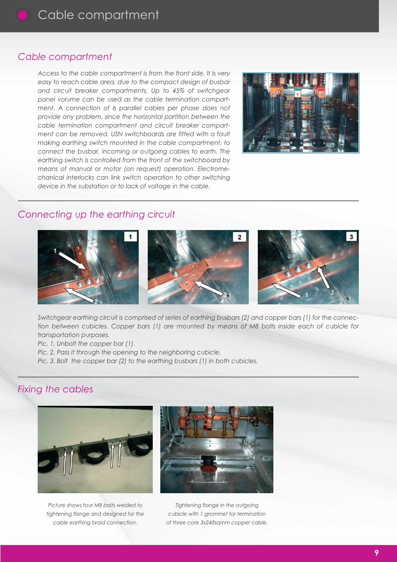
Access to the cable compartment is from the front side. It is very easy to reach cable area, due to the compact design of busbar and circuit breaker compartments. Up to 45% of switchgear panel volume can be used as the cable termination compart-ment. A connection of 6 parallel cables per phase does not provide any problem, since the horizontal partition between the cable termination compartment and circuit breaker compart-ment can be removed. USN switchboards are fitted with a fault making earthing switch mounted in the cable compartment, to connect the busbar, incoming or outgoing cables to earth. The earthing switch is controlled from the front of the switchboard by means of manual or motor (on request) operation. Electrome-chanical interlocks can link switch operation to other switching device in the substation or to lack of voltage in the cable.
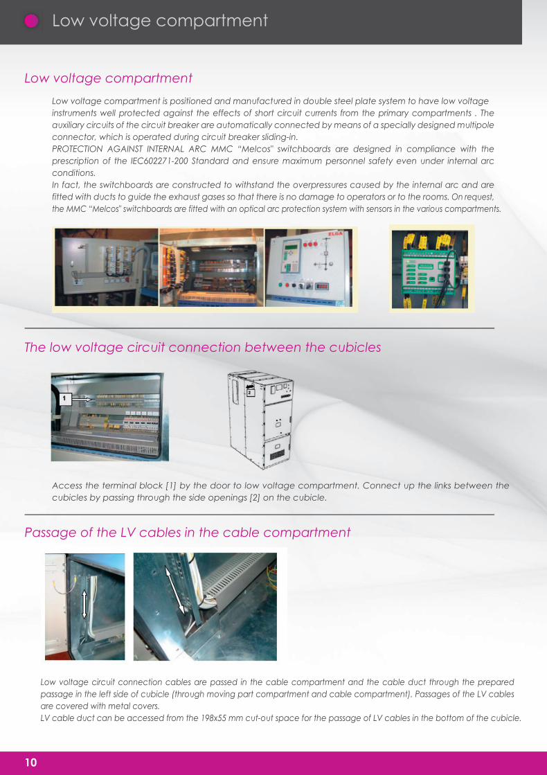
Switchgear earthing circuit is comprised of series of earthing busbars (2) and copper bars (1) for the connec-tion between cubicles. Copper bars (1) are mounted by means of M8 bolts inside each of cubicle for transportation purposes. Pic. 1. Unbolt the copper bar (1).Pic. 2. Pass it through the opening to the neighboring cubicle.Pic. 3. Bolt the copper bar (2) to the earthing busbars (1) in both cubicles.
9
Connecting up the earthing circuit
Fixing the cables
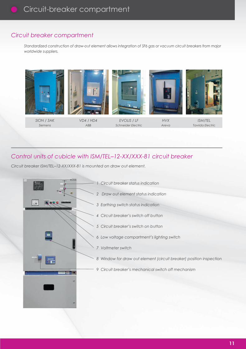
Picture shows four M8 bolts welded to
tightening flange and designed for the
cable earthing braid connection.
Tightening flange in the outgoing
cubicle with 1 grommet for termination
of three core 3x240sqmm copper cable.
Low voltage compartment
Low voltage compartment
Low voltage compartment is positioned and manufactured in double steel plate system to have low voltageinstruments well protected against the effects of short circuit currents from the primary compartments . The auxiliary circuits of the circuit breaker are automatically connected by means of a specially designed multipole connector, which is operated during circuit breaker sliding-in.PROTECTION AGAINST INTERNAL ARC MMC “Melcos" switchboards are designed in compliance with the prescription of the IEC602271-200 Standard and ensure maximum personnel safety even under internal arc conditions.In fact, the switchboards are constructed to withstand the overpressures caused by the internal arc and are fitted with ducts to guide the exhaust gases so that there is no damage to operators or to the rooms. On request, the MMC “Melcos" switchboards are fitted with an optical arc protection system with sensors in the various compartments.
Access the terminal block [1] by the door to low voltage compartment. Connect up the links between the cubicles by passing through the side openings [2] on the cubicle.
Low voltage circuit connection cables are passed in the cable compartment and the cable duct through the prepared passage in the left side of cubicle (through moving part compartment and cable compartment). Passages of the LV cables are covered with metal covers.LV cable duct can be accessed from the 198x55 mm cut-out space for the passage of LV cables in the bottom of the cubicle.
10
The low voltage circuit connection between the cubicles
Passage of the LV cables in the cable compartment
Circuit-breaker compartment
11
Circuit breaker compartment
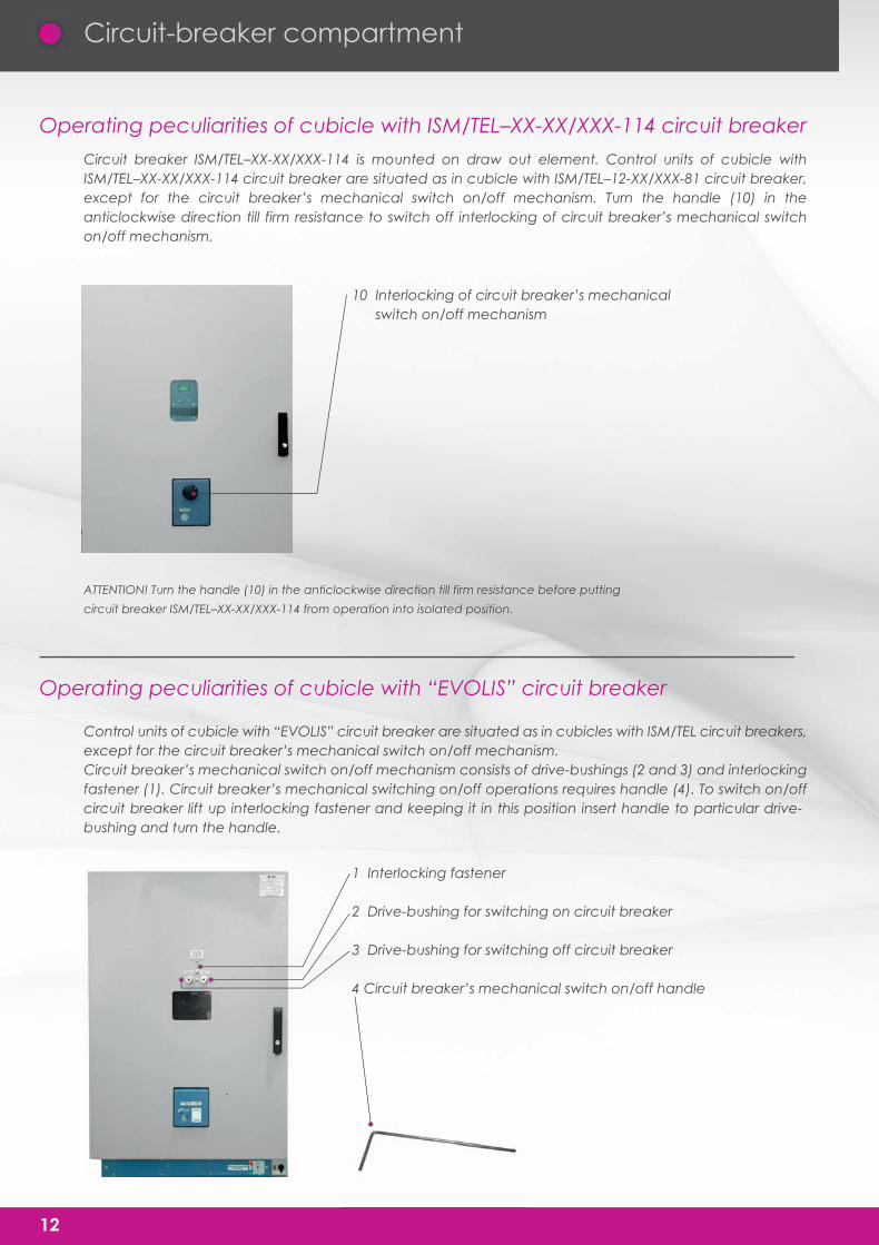
Standardized construction of draw-out element allows integration of SF6 gas or vacuum circuit breakers from majorworldwide suppliers.
SION / 3AK VD4 / HD4 EVOLIS / LF HVX ISM/TELSiemens ABB Schneider Electric Areva Tavrida Electric
Control units of cubicle with ISM/TEL–12-XX/XXX-81 circuit breaker
Circuit breaker ISM/TEL–12-XX/XXX-81 is mounted on draw out element.
1 Circuit breaker status indication
2 Draw out element status indication
3 Earthing switch status indication
4 Circuit breaker’s switch off button
5 Circuit breaker’s switch on button
6 Low voltage compartment’s lighting switch
7 Voltmeter switch
8 Window for draw out element (circuit breaker) position inspection
9 Circuit breaker’s mechanical switch off mechanism
Circuit-breaker compartment
Circuit breaker ISM/TEL–XX-XX/XXX-114 is mounted on draw out element. Control units of cubicle with ISM/TEL–XX-XX/XXX-114 circuit breaker are situated as in cubicle with ISM/TEL–12-XX/XXX-81 circuit breaker, except for the circuit breaker’s mechanical switch on/off mechanism. Turn the handle (10) in the anticlockwise direction till firm resistance to switch off interlocking of circuit breaker’s mechanical switch on/off mechanism.
Control units of cubicle with “EVOLIS” circuit breaker are situated as in cubicles with ISM/TEL circuit breakers, except for the circuit breaker’s mechanical switch on/off mechanism.Circuit breaker’s mechanical switch on/off mechanism consists of drive-bushings (2 and 3) and interlocking fastener (1). Circuit breaker’s mechanical switching on/off operations requires handle (4). To switch on/off circuit breaker lift up interlocking fastener and keeping it in this position insert handle to particular drive-bushing and turn the handle.
12
10 Interlocking of circuit breaker’s mechanical switch on/off mechanism
1 Interlocking fastener
2 Drive-bushing for switching on circuit breaker
3 Drive-bushing for switching off circuit breaker
4 Circuit breaker’s mechanical switch on/off handle
Operating peculiarities of cubicle with ISM/TEL–XX-XX/XXX-114 circuit breaker
Operating peculiarities of cubicle with “EVOLIS” circuit breaker
ATTENTION! Turn the handle (10) in the anticlockwise direction till firm resistance before putting
circuit breaker ISM/TEL–XX-XX/XXX-114 from operation into isolated position.
Circuit-breaker compartment
Control units of cubicle with “SION” circuit breaker are situated as in cubicles with ISM/TEL circuit breakers, except for the circuit breaker’s mechanical switch on/off mechanism.Circuit breaker’s mechanical switch on/off mechanism consists of drive-bushings (1 and 2) and interlo-cking fastener (3). Circuit breaker’s mechanical switching on/off operations requires handle (4). To switch on/off circuit breaker lift up interlocking fastener and keeping it in this position insert handle to particular drive-bushing and turn the handle.
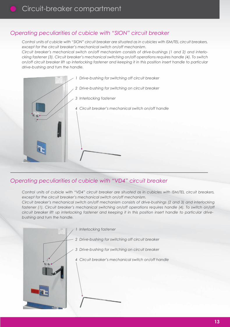
Control units of cubicle with “VD4” circuit breaker are situated as in cubicles with ISM/TEL circuit breakers, except for the circuit breaker’s mechanical switch on/off mechanism.Circuit breaker’s mechanical switch on/off mechanism consists of drive-bushings (2 and 3) and interlocking fastener (1). Circuit breaker’s mechanical switching on/off operations requires handle (4). To switch on/off circuit breaker lift up interlocking fastener and keeping it in this position insert handle to particular drive-bushing and turn the handle.
13
1 Drive-bushing for switching off circuit breaker
2 Drive-bushing for switching on circuit breaker
3 Interlocking fastener
4 Circuit breaker’s mechanical switch on/off handle
1 Interlocking fastener
2 Drive-bushing for switching off circuit breaker
3 Drive-bushing for switching on circuit breaker
4 Circuit breaker’s mechanical switch on/off handle
Operating peculiarities of cubicle with “SION” circuit breaker
Operating peculiarities of cubicle with “VD4” circuit breaker
Packaging - Handling - Storage
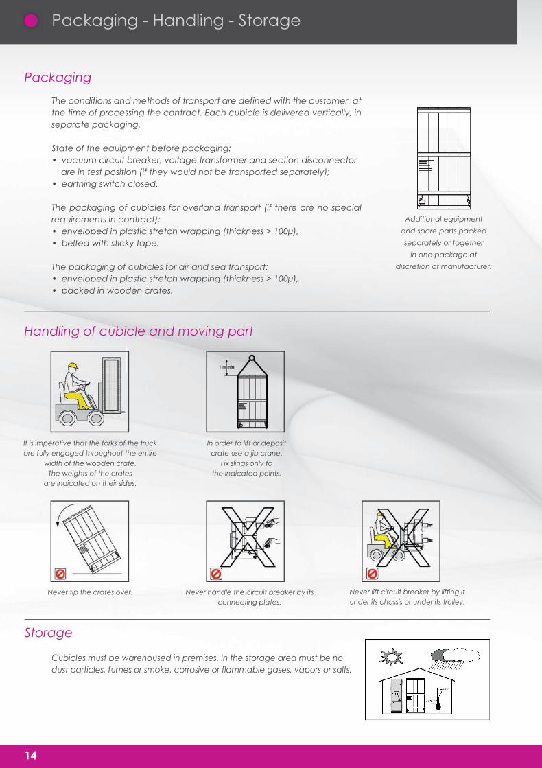
The conditions and methods of transport are defined with the customer, at the time of processing the contract. Each cubicle is delivered vertically, in separate packaging.
State of the equipment before packaging:• vacuum circuit breaker, voltage transformer and section disconnector are in test position (if they would not be transported separately);• earthing switch closed.
The packaging of cubicles for overland transport (if there are no special requirements in contract):• enveloped in plastic stretch wrapping (thickness > 100μ),• belted with sticky tape.
The packaging of cubicles for air and sea transport:• enveloped in plastic stretch wrapping (thickness > 100μ),• packed in wooden crates.
Cubicles must be warehoused in premises. In the storage area must be no dust particles, fumes or smoke, corrosive or flammable gases, vapors or salts.
14
Additional equipment
and spare parts packed
separately or together
in one package at
discretion of manufacturer.
It is imperative that the forks of the truckare fully engaged throughout the entire
width of the wooden crate.The weights of the crates
are indicated on their sides.
In order to lift or depositcrate use a jib crane.
Fix slings only tothe indicated points.
Never tip the crates over. Never handle the circuit breaker by itsconnecting plates.
Never lift circuit breaker by lifting itunder its chassis or under its trolley.
Packaging
Handling of cubicle and moving part
Storage

Unpacking and installation of the equipment
The installation of a switchboard requires a sufficiently flat and even concrete structure. The dressing of a top coat finish of cement with a straight edge should eliminate any surface irregularities and declivities of greater than 2mm per meter. The overall flatness of the support surface should not show up any deflection greater than 5 mm. Floor, ceiling and walls of the building must be finished with materials, which not raise or collect dust
Unpacking c ubicles should only take place on the installation site. Remove sticky tape and plastic stretch wrapping from cubicle (the easiest way to do it by lifting cubicle 100-200 mm from floor – see “Handling cubicles”). Visually inspect the exterior of cubicle.
15
Four slinging points are providedfor on the roof of each cubicle.
Fix protected steel cablesonly to the indicated fixing points.
On the ground, prepare 2 stringersthat will be aligned
with the outer edges of the truck.
Lift the cubicle unit by 4 slingseach one capable
of supporting 1,000 kg.
Slide the cubicle along, using threecylindrical rollers of 30mm min. diam.
Thus moving it to its final installation point.
Type of Building Structural Work
Unpacking cubicles
Handling cubicles
Handling the moving part for placing it on the ground
Unpacking and installation of the equipment
16
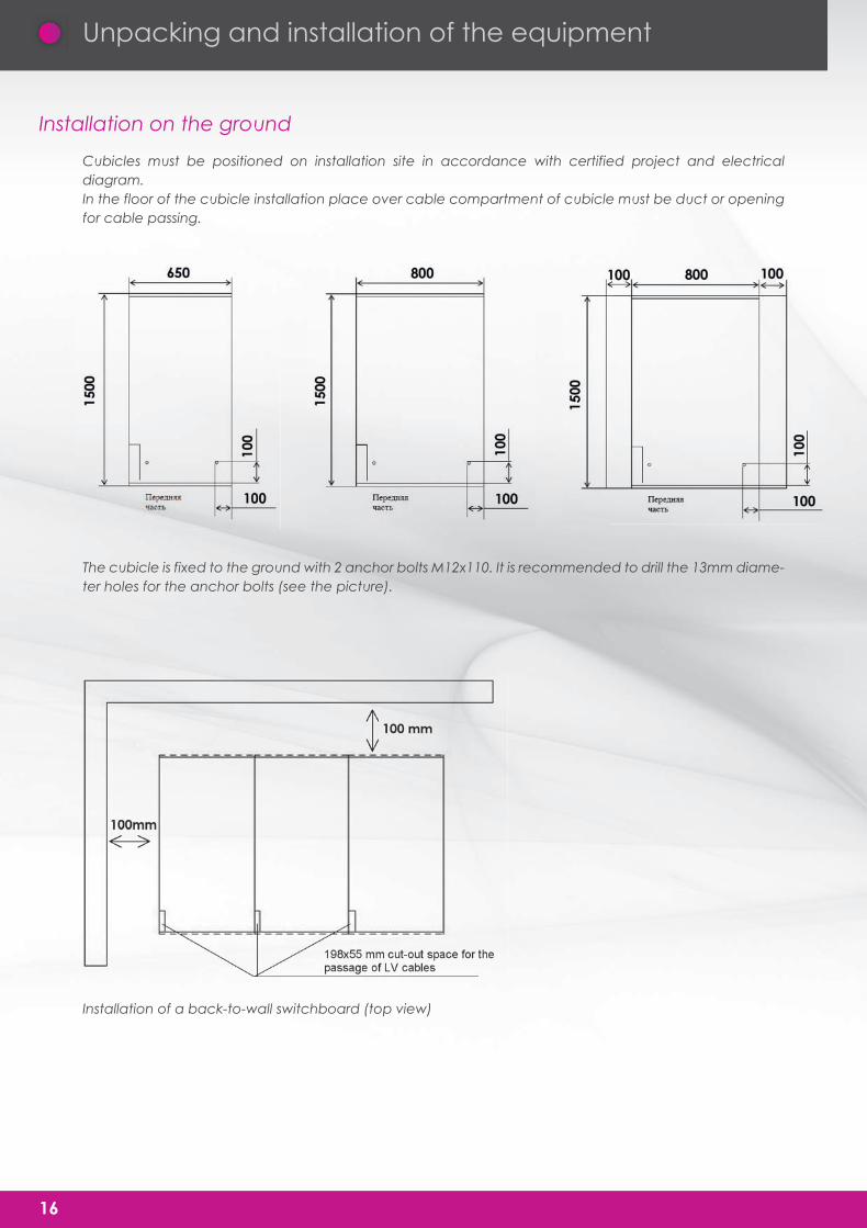
Installation on the ground
Cubicles must be positioned on installation site in accordance with certified project and electrical diagram.In the floor of the cubicle installation place over cable compartment of cubicle must be duct or opening for cable passing.
The cubicle is fixed to the ground with 2 anchor bolts M12x110. It is recommended to drill the 13mm diame-ter holes for the anchor bolts (see the picture).
Installation of a back-to-wall switchboard (top view)
Extraction of draw out element with moving part (circuit breaker, section disconnector, voltage transfor-mer) described in 20 page.
Unpacking and installation of the equipment
17
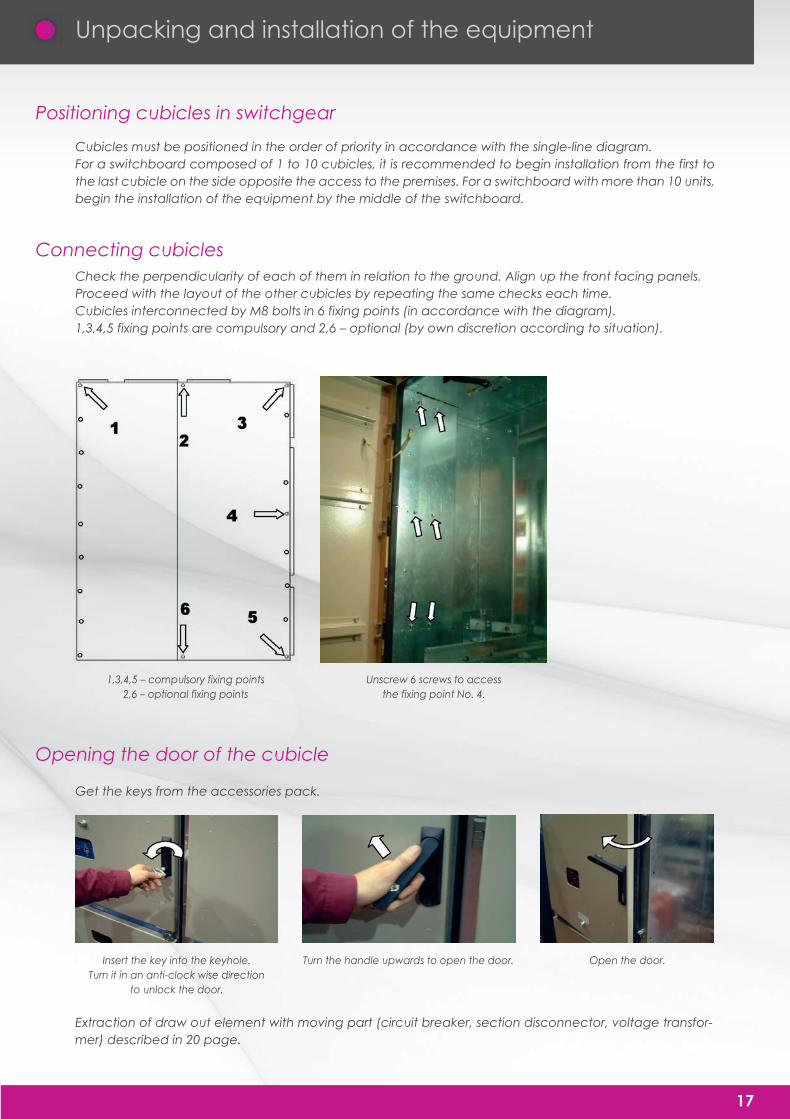
Insert the key into the keyhole.Turn it in an anti-clock wise direction
to unlock the door.
1,3,4,5 – compulsory fixing points2,6 – optional fixing points
Unscrew 6 screws to accessthe fixing point No. 4.
Turn the handle upwards to open the door. Open the door.
Positioning cubicles in switchgear
Connecting cubicles
Opening the door of the cubicle
Cubicles must be positioned in the order of priority in accordance with the single-line diagram.For a switchboard composed of 1 to 10 cubicles, it is recommended to begin installation from the first to the last cubicle on the side opposite the access to the premises. For a switchboard with more than 10 units, begin the installation of the equipment by the middle of the switchboard.
Check the perpendicularity of each of them in relation to the ground. Align up the front facing panels.Proceed with the layout of the other cubicles by repeating the same checks each time.Cubicles interconnected by M8 bolts in 6 fixing points (in accordance with the diagram).1,3,4,5 fixing points are compulsory and 2,6 – optional (by own discretion according to situation).
Get the keys from the accessories pack.
Operating accessories
18
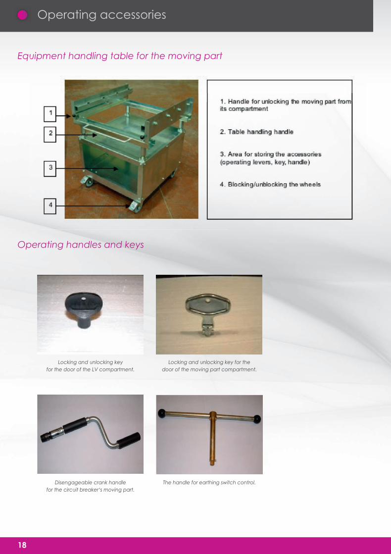
Equipment handling table for the moving part
Operating handles and keys
Locking and unlocking keyfor the door of the LV compartment.
Locking and unlocking key for thedoor of the moving part compartment.
Disengageable crank handlefor the circuit breaker‘s moving part.
The handle for earthing switch control.

Notes

Notes

M.EL.COS. si riserva il diritto di modificare i prodotti
presenti in questo catalogo in qualsiasi momento
e senza alcun preavviso.
M.EL.COS. has the right to modify the products in
this catalogue at any time and without any notice

M.EL.COS S.n.c.
ALBERORO
TEGOLETO
Gro
sse
to-F
ano
Gro
sset
o-Fa
no
Via A
retin
a
Via A
retin
a
BORGHETTO -LENEBBIAIE
MONTAGNANO
SAN LUCIANO
PIEVE ALTOPPO
MONTESAN SAVINO
DirezioneAREZZO
AutostradaDel Sole
DIREZIONE FIRENZE
DIREZIONE ROMA DIREZIONE FOIANO
AutostradaDel Sole
Via Leopoldodi Toscana 9/1152048 Alberoro (AR)
Via Leopoldo
Sede Legale, Amministrativa e Produzione
Headquarter and Production
Via Leopoldo di Toscana 9/11
52048 Alberoro (AR) -ITALY-
T. +39 0575 848096
F. +39 0575 848098
P.IVA 01047770514
Direzione Commerciale
Sales Direction
Via Indipendenza 65/b
20821 Meda (MB) -ITALY-
T. +39 0362 347769
F. +39 02 73960372