7sj61-63
TRANSCRIPT
SIPROTEC 47SJ61/62/63 6MD63Multifunction Protection Relay and Bay Controller
ProtectionSystems
CatalogSIP 3.11999


Siemens SIP 3.1 ⋅1999 2
SIPROTEC 47SJ61/62/63 6MD63Multifunction Protection Relayand Bay ControllerFirmware Version 4.1
Protection Systems
Functions Page 12 to 24
Typical application Page 25 to 32
SIPROTEC 4 7SJ61
SIPROTEC 4 7SJ63
Unit dataSelection andordering dataConnectiondiagramDimensiondrawingsPage 50 to 58
Unit dataSelection andordering dataConnectiondiagramDimensiondrawingsPage 68 to 81
Catalog SIP 3.1 ⋅ 1999
Siemens AG 1999
Description/overview Page 2 to 11
Technical data Page 33 to 44
SIPROTEC 4 7SJ62
Unit dataSelection andordering dataConnectiondiagramDimensiondrawingsPage 60 to 67
SIPROTEC 4 6MD63
~ Advantages to youn Cost-effectiveness
n High degree of automation
n User-friendly operation
n Low planning and engineeringeffort
n Fast, flexible mounting, reducedwiring
n Simple, short commissioning
n Simple spare part stocking
n High flexibility
n High reliability and availability
n State-of-the-art technology
n Compliance with internationalstandards
n Integration in the overall systemSIPROTEC 4-SICAM-SIMATIC
Overview ofSIPROTEC 4 units Page 46 and 47
Unit dataSelection andordering dataConnectiondiagramDimensiondrawingsPage 82 to 96
2 Siemens SIP 3.1 ⋅ 1999
SIPROTEC 4 7SJ61/62/63 / 6MD63Multifunction Protection Relay and Bay Controller
Description
Application
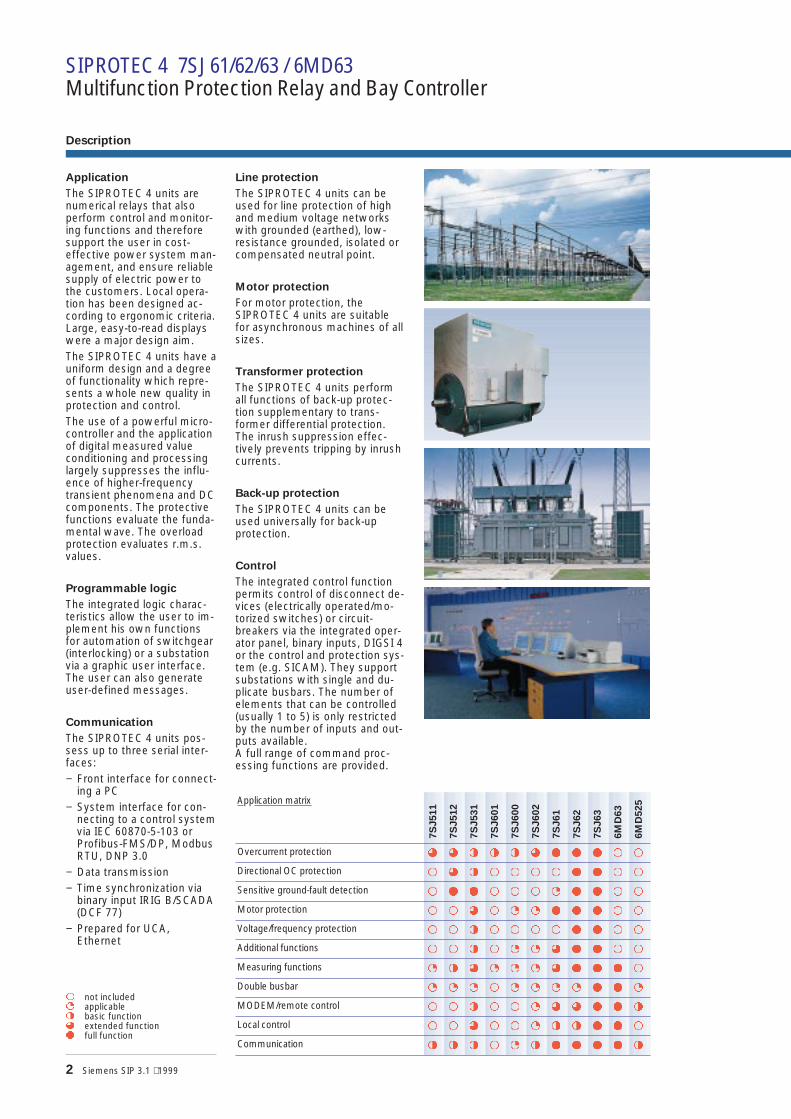
The SIPROTEC 4 units arenumerical relays that alsoperform control and monitor-ing functions and thereforesupport the user in cost-effective power system man-agement, and ensure reliablesupply of electric power tothe customers. Local opera-tion has been designed ac-cording to ergonomic criteria.Large, easy-to-read displayswere a major design aim.The SIPROTEC 4 units have auniform design and a degreeof functionality which repre-sents a whole new quality inprotection and control.The use of a powerful micro-controller and the applicationof digital measured valueconditioning and processinglargely suppresses the influ-ence of higher-frequencytransient phenomena and DCcomponents. The protectivefunctions evaluate the funda-mental wave. The overloadprotection evaluates r.m.s.values.
Programmable logic
The integrated logic charac-teristics allow the user to im-plement his own functionsfor automation of switchgear(interlocking) or a substationvia a graphic user interface.The user can also generateuser-defined messages.
Communication
The SIPROTEC 4 units pos-sess up to three serial inter-faces:− Front interface for connect-
ing a PC− System interface for con-
necting to a control systemvia IEC 60870-5-103 orProfibus-FMS/DP, ModbusRTU, DNP 3.0
− Data transmission− Time synchronization via
binary input IRIG B/SCADA(DCF 77)
− Prepared for UCA,Ethernet
Line protection
The SIPROTEC 4 units can beused for line protection of highand medium voltage networkswith grounded (earthed), low-resistance grounded, isolated orcompensated neutral point.
Motor protection
For motor protection, theSIPROTEC 4 units are suitablefor asynchronous machines of allsizes.
Transformer protection
The SIPROTEC 4 units performall functions of back-up protec-tion supplementary to trans-former differential protection.The inrush suppression effec-tively prevents tripping by inrushcurrents.
Back-up protection
The SIPROTEC 4 units can beused universally for back-upprotection.
Control
The integrated control functionpermits control of disconnect de-vices (electrically operated/mo-torized switches) or circuit-breakers via the integrated oper-ator panel, binary inputs, DIGSI 4or the control and protection sys-tem (e.g. SICAM). They supportsubstations with single and du-plicate busbars. The number ofelements that can be controlled(usually 1 to 5) is only restrictedby the number of inputs and out-puts available.A full range of command proc-essing functions are provided.
Application matrix
7S
J511
7S
J512
7S
J531
7S
J601
7S
J600
7S
J602
7S
J61
7S
J62
7S
J63
6M
D63
6M
D525
Overcurrent protection $ $ § § § $ % % % ! !
Directional OC protection ! $ § ! ! ! ! % % ! !
Sensitive ground-fault detection ! % % ! ! ! " % % ! !
Motor protection ! ! $ ! " " % % % ! !
Voltage/frequency protection ! ! § ! ! ! ! % % ! !
Additional functions ! ! § ! " " $ % % ! !
Measuring functions " § $ " " " $ % % % !
Double busbar " " " ! " " " " % % "
MODEM/remote control ! ! § ! ! " $ $ % % §
Local control ! ! $ ! ! " § § % % !
Communication § § § ! " § % % % % §
! not included" applicable§ basic function$ extended function% full function

Siemens SIP 3.1 ⋅ 1999 3Siemens SIP 3.1 ⋅ 1999 3
Time synchronization
A battery-backed clock is astandard component and canbe synchronized via a syn-chronization signal (DCF77,IRIG B via satellite receiver),binary input, system inter-face or SCADA (e.g. SICAM).A date and time is assignedto every indication.
Selectable binary inputsand outputs
Binary inputs, outputs andLEDs can be assigned to per-form specific functions as de-fined by the user.
Selectable function keys
Four function keys can be as-signed to permit the user toperform frequently recurringactions very quickly and sim-ply.Typical applications are, forexample, jumps to a givenposition in the menu tree inorder to display the list of op-erating indications or to per-form automatic functions,such as “Switching ofcircuit-breaker”.
Continuous self-monitoring
The hardware and softwareare continuously monitored.If abnormal conditions aredetected, the units signalsimmediately. In this way, agreat degree of safety, relia-bility and availability isachieved.
Reliable battery monitoring
The battery that is providedis used to back-up the clock,switching statistics, thestatus and fault indicationsand the fault recording in theevent of a power supply fail-ure. Its function is checkedby the processor at regularintervals. If the capacity ofthe battery is found to be de-clining, an alarm is gener-ated. Regular replacement istherefore not necessary.All setting parameters arestored in the Flash-EPROMwhich are not lost if thepower supply or battery fails.The SIPROTEC 4 unit re-mains fully functional.
Protection functions
The SIPROTEC 4 units areavailable with a variety ofprotective functions. Pre -defined application packagescan be implemented to makeselection easier for the user.
Metering values
Extensive measured values,limit values and metered val-ues permit improved systemmanagement, as well as sim-plified commissioning.
Transducer
Uses two 4 to 20 mA inputinterfaces.
Operational indications
Indications with timestamp
The SIPROTEC 4 unitsprovide extensive data forfault analysis, as well as con-trol. All indications listedbelow are protected againstpower supply failure.n Fault signals
The last eight fault casesand 3 sensitive ground faultcases are always stored inthe unit. All fault recordingsare time stamped with aresolution of 1 msec.
n Operational indicationsAll indications that are notdirectly associated with thefault (e.g. operating orswitching actions) arestored in the status indica-tion buffer. The time resolu-tion is 1 ms, buffer size: 80indications.
Fault recording up to 5 sec-onds
The digitized values forphase currents, ground(earth) currents, line andzero-sequence currents arerecorded in a fault recording.The record can be startedusing a binary input, on initia-tion or when a trip commandoutput occurs. Up to eightfault recordings may bestored. For test purposes, itis possible to start a fault re-cording via DIGSI 4 or theconnected control and pro-tection system.
Fig. 1
Single-line diagram

4 Siemens SIP 3.1 ⋅ 1999
Description
n Operation
User-friendly local opera-tion
Many advantages are alreadyto be found on the clear anduser-friendly front panel:n Positioning and grouping of
the keys supports the natu-ral operating process
n Large non-reflective back-litdisplay
n Programmable (freely as-signable) LEDs for impor-tant messages
n Arrows arrangement of thekeys for easy navigation inthe function tree
n Operator-friendly input ofthe setting values via thenumeric keys or DIGSI 4
n Command input protectedby key lock (6MD63/7SJ63only) or password
n Four programmable keysfor frequently used func-tions >at the press of a but-ton<
Local operation
All operator actions can beexecuted and informationdisplayed on an integrateduser interface:
t
On the LCD display, process and device infor-mation can be displayed as text in variouslists. Frequently displayed information in-cludes measured analog values, metered val-ues, binary information about the state of theswitchgear and the device, protection infor-mation, general indications and alarms.
t
Seven configurable (parameterizable) LEDsare used to display any process or device in-formation. The LEDs can be labeled based onuser requirements. An LED reset key resetsthe LEDs.
s
Four configurable function keys permit theuser to execute frequently used actions fastand simple. Typical applications include jumpsto certain points in the menu tree to displaythe operational measured values, or executionof automatic functions such as: “Operate thecircuit-breaker”
s
Keys for navigation
Fig. 2
SIPROTEC 4 7SJ61/62
Fig. 3
Example for application of F keys
RS232 operator interface
SIPROTEC 4 7SJ61/62/63 / 6MD63Multifunction Protection Relay and Bay Controller
s
Numerical keys for data entry
LSP
2059
usa.
tif
Measuredvalues
Disturbance
CLOSE
OPEN
LSP
2098
usa.
eps

Siemens SIP 3.1 ⋅ 1999 5Siemens SIP 3.1 ⋅ 1999 5
t
On the large LCD display process and device informationcan be displayed as a one-line diagram or as text in dif-ferent lists. Frequently displayed information includesmeasured analog values, metered values, binary infor-mation about the status of the switchgear and the de-vices, protection information, general indications andalarms.
Local operation
All operator actions can beexecuted and informationdisplayed on an integrateduser interface:
s
The keys for navigating in the menu of the function tree,the one-line diagram or entering values are positionedfrom top to bottom on an axis to the right of the display.
s
Below the LCD there are highlighted keys used forcontrolling the process. For typical switching operations,these keys are used from left to right.
s
Four configurable function keys permit the user toinitiate frequently used actions fast and simply. Typicalapplications include jumps to certain points in the menutree to display the list of operational measured values, orexecution of automatic functions such as applying safetygrounds.
s
14 configurable LEDs are used to display any process ordevice information. The LEDs can be labeled application-specifically. An LED reset key resets the LEDs.
s
Two key switches ensure fast and reliable access to“switch between local and remote control” and “switchbetween interlocked and non-interlocked operation“.
Fig. 4
SIPROTEC 4 7SJ63/6MD63
LSP
2057
usa.
tif
s
RS232 operator interface
t
Numerical keys for data entry

6 Siemens SIP 3.1 ⋅ 1999
DIGSI 4 Operating program
DIGSI 4, the PC programfor operating SIPROTEC 4under MS Windows 95/98/NT 4.0
The PC operating programDIGSI 4 is the interfacebetween the user and theSIPROTEC 4 units. It has amodern, intuitive operator in-terface. With DIGSI 4, theSIPROTEC 4 units can beconfigured and queried - it isa tailored program for theenergy and manufacturingsupply industries.
DIGSI 4 matrix
The DIGSI 4 matrix allowsthe user to see the overallview of the unit configurationat a glance. For example, youcan display all the LEDs thathave binary inputs or showany indication that are con-nected to the relay. And withone click of the button con-nections can be switched.
Fig. 5
DIGSI 4 allocation matrix
Fig. 6
Substation manager for managingof substation and device data
LSP
2129
f.tif
LSP
2121
f.tif
Fig. 7
Range of operational measuredvalues
Fig. 8
Function range
LSP
2123
f.tif
SIPROTEC 4 7SJ61/62/63 / 6MD63Multifunction Protection Relay and Bay Controller
LSP
2120
f.tif
LSP
2122
f.tif

Siemens SIP 3.1 ⋅ 1999 7Siemens SIP 3.1 ⋅ 1999 7
Fig. 11
CFC logic with module library
LSP
2104
f.tif
Fig. 9
Display Editor
LSP
2025
f.tif
LSP
2128
f.tif
Fig. 10
Commissioning aid
Display editor
A display editor is available todesign the display onSIPROTEC 4 units. The pre-defined symbol sets can beexpanded to suit the user.The drawing of an one-line di-agram is extremely simple.Operational measured values(analog values) in the unit canbe placed where required.
Commissioning
Special attention has beenpaid to commissioning. All bi-nary inputs and outputs canbe read and set directly. Thiscan simplify the wire check-ing process significantly forthe user.
CFC: Reduced time andplanning for programminglogic
With the help of the CFC(Continuous Function Chart),you can configure interlocksand switching sequencessimply by drawing the logicsequences; no special knowl-edge of software is required.Logical elements, such asAND, OR and time elements,measured limit values, etc.are available.Use the true full PLC func-tionality according to IEC toreduce time and planning.
The new DIGSI 4n Easy to learn
n Clear layout of routing matrix
n Substation, feeder and equipmentdata management
n Password protection
n Linked with the SICAM/SIMATICsoftware environment
nWindows 95/98 standards
~

8 Siemens SIP 3.1 ⋅ 1999
SIPROTEC 4/SICAM system/SCADA
SIPROTEC 4 as integral part of SICAMenergy automation system
SIPROTEC 4 is tailor-made for use in theSIMATIC-based SICAM energy automa-tion system.The SICAM family consists of the fol-lowing components:n SICAM RTU, the modern telecontrol
system with automation and PLC func-tions
n SICAM SAS, the modern integration ofswitchgear automation and informa-tion technology
n SICAM PCC, the information and com-munication technology on a PC basis
Software data management and com-munication is one of the strong-points ofcombining of SICAM and SIPROTEC 4.Powerful engineering tools (SICAM plusTOOLS on the basis of STEP7 andSICAM WinCC) make working withSICAM convenient. The SIPROTEC 4units are optimally matched for use inSICAM SAS and SICAM PCC.With SICAM and SIPROTEC 4 continuityexists at three central points:n Data managementn Software architecturen Communication.All central system components (SICAMand SIPROTEC 4 CPUs, SICAM WinCC,SICAM plus TOOLS, bay controllers andprotection equipment), as well as theDIGSI 4 operating program, are estab-lished on the same basis.The interface and ability to link SICAM/SIPROTEC and other components of thesubstation control, protection and auto-mation is assured via open interfaces,such as IEC 60870-5-103 or PROFIBUS.
Service bus
DIGSI 4 offers the additional possibilityof accessing bay controllers via modem.It is possible to read out from the officedesk or when travelling (by laptop andmodem) the operational and fault eventlogs, fault records, as well as opera-tional measured values of all protectiondevices of an installation. This permitsrapid and extensive access for the serv-ice personnel.
Star coupler
All SIPROTEC units operate also withthe proven star coupler. The star coupleris used for simple applications whichalso give the user an alternate methodof retrieving information remotely.
Fig. 13
Systems control bus and service bus
Fig. 12
SICAM/SIPROTEC 4 architecture
Office/SCADA
Modemaccess
Rear of unitSIPROTEC 4
Front interface
Rear of unitSIPROTEC 4
Front interface
Rear of unitSIPROTEC 4
Front interface
Systems control
SICAM/SIPROTEC 4
Database
SICAM WinCC
DIGSI 4
SICAM plusTOOLS
Bay control units
Data mana-gement
Software Communi-cation
IEC 60870-5-103Profibus FMS/DPModbus RTU, DNP 3.0
SCADA
CPU
Centralinput/output
Protection devices
IEC 60870-5-103/Profibus-FMS/DP
Modbus RTU
SIPROTEC 4 7SJ61/62/63 / 6MD63Multifunction Protection Relay and Bay Controller
Service vehicle
DNP 3.0
DIGSI 4

Siemens SIP 3.1 ⋅ 1999 9Siemens SIP 3.1 ⋅ 1999 9
Fig. 14
SICAM SAS
Fig. 15
Star coupler
SICAM WinCCOperation and monitoringarchive, configuration station
Telecontrol interface tosystem control centers(e.g. IEC 60870-5-101)
DIGSI 4PC or notebook
Automationsystems(e.g. SIMATIC)
TimesynchronizationDGF, GPS
SICAM SCIEC 60870-5-103
Profibus FMS
ControlProtection/controlProtection 1) Protection and control
in separate units2) Protection and control
in one unit
7SJ6007SA5117UT51SD517SJ51
6MB525
1)2) 2) 1) 2) 1) 2)
1)
7SJ61/62 6MD/7SJ63 6MB525 7SJ61/62 6MD63 7SJ637SJ61/626MD63
IEC 60870-5-103

10 Siemens SIP 3.1 ⋅ 1999
With respect to communica-tion, particular emphasis isplaced on the requirementscustomary in energy automa-tion:n Every data item is time-
stamped at the source, i.e.where it originates.
n The communication systemautomatically handles thetransfer of large data blocks(e.g. fault recordings or pa-rameter data files). Theuser can apply thesefeatures without anyadditional programming ef-fort.
n For the reliable execution ofa command, the relevantsignal is first acknowledgedin the unit involved. Whenthe command has been en-abled and executed, acheck-back indication is is-sued. The actual conditionsare checked at every com-mand handling step. When-ever they are not satisfied,controlled interruption ispossible.
Local PC interface
The PC interface accessiblefrom the front of the unit per-mits quick access to all pa-rameters and fault eventdata. Of particular advantageis the use of the DIGSI 4 op-erating program during com-missioning.
Safe bus architecture
n RS485 busWith this data transmissionvia copper conductors elec-tromagnetic fault influ-ences are largely elimi-nated by the use oftwisted-pair conductor.Upon failure of a unit, theremaining system contin-ues to operate without anyfaults.
n Fiber-optic double ring cir-cuitThe fiber-optic double ringcircuit is immune to electro-magnetic interference.Upon failure of a sectionbetween two units, thecommunication systemcontinues to operate with-out disturbance.
It is generally impossible tocommunicate with a unitthat has failed. If a unitwere to fail, there is no ef-fect on the communicationwith the rest of the system.
Retrofitting: Modules forevery type of communica-tion
Communication modules areavailable for the entireSIPROTEC 4 unit range.This ensures that a range ofcommunication protocols canbe used (DNP 3.0, ModbusRTU, UCA, IEC 60870-5-103,Profibus, DIGSI). No externalconverter is required.
IEC 60870-5-103
IEC 60870-5-103 is an inter-nationally standardized proto-col for the efficient solving ofcommunication problems inthe protected area.IEC 60870-5-103 is sup-ported by a number of pro-tection device manufacturersand is used world-wide.
Profibus-FMS
Profibus-FMS is an interna-tionally standardized commu-nication system (EN 50170)for communication problemsolving. Profibus is supportedinternationally by severalhundred manufacturers andhas to date (status as at mid1997) been used in morethan 1,000,000 applicationsall over the world.Connection to a SIMATIC S5/S7programmable controller ismade on the basis of thedata obtained (e.g. fault re-cording, fault data, measuredvalues and control functional-ity) via SICAM energy auto-mation system or viaProfibus DP.
Profibus DP
Profibus DP is an industryrecognized standard forcommmunications and issupported by a number ofPLC and protection devicemanufacturers.
Modbus RTU
Modbus RTU is an industryrecognized standard for com-munications and is supportedby a number of PLC andprotection device
Fig. 16
Communication mod-ule for retrofitting
Fig. 17 IEC 60870-5-103 star-type RS232 copper conductorconnection or fibre-optic connection
Fig. 18 Profibus: Optical double ring circuit
1) Optical Link Module
OLM1)
Communication
LSP
2051
a.ep
s
SIPROTEC 4 7SJ61/62/63 / 6MD63Multifunction Protection Relay and Bay Controller
DNP 3.0
DNP 3.0 (DistributedNetwork Protocol version 3)is a messaging based com-munications protocol. TheSIPROTEC 4 units are fullyLevel 1 and Level 2 compli-ant with DNP 3.0. DNP 3.0 issupported by a number ofprotection device manufac-turers.
UCA
UCA (UtilityCommunications Architec-ture) is a developing commu-nications protocol specificallydesigned for substation auto-mation. When it becomes aninternational standard, theSIPROTEC 4 units are pre-pared to support it. Simplyplug in a new communicationmodule.

Siemens SIP 3.1 ⋅ 1999 11Siemens SIP 3.1 ⋅ 1999 11
Fig. 19
NXAir panel (air-insulated)
Switchgear cubicles forhigh/medium voltage
All units are designed specificallyto meet the requirements ofhigh/medium-voltage applica-tions.In general, no separate measur-ing instruments (e.g. for current,voltage, frequency, measuringtransducer...) or additional con-trol components are necessary.
LSP
2077
f.ep
s
LSP
2112
usa.
tifLS
P21
13us
a.tif
LSP
2066
usa.
tifLS
P20
67us
a.tif
Fig. 21
Display examples 7SJ62
Operational measured values
Fault display
Fig. 20
NXPlus panel (gas-insulated)
Measured values
The RMS values are calculated from theacquired current and voltage along withthe power factor, frequency, active andreactive power. The following functionsare available for measured value proc-essing:n Currents IA, IB, IC, IN, IEE (67Ns)n Voltages VA, VB, VC, VAB, VBC, VCA
n Symmetrical components I1, I2,3I0; V1, V2, 3V0
n Power Watts, Vars, VA /P, Q, Sn Power factor (cos ϕ)n Frequencyn Energy ± kWh, ± kVarh, forward and
reverse power flownMean as well as minimum and maxi-
mum current and voltage valuesn Operating hours counternMean operating temperature of over-
load functionn Limit value monitoring
Limit values are monitored using pro-grammable logic in the CFC. Com-mands can be derived from this limitvalue indication.
n Zero suppressionIn a certain range of very low meas-ured values, the value is set to zero tosuppress interference.
Metered values
For internal metering, the unitcan calculate an energy meteredvalue from the measured currentand voltage values. If an externalmeter with a metering pulse out-put is available, the SIPROTEC 4unit can obtain and process me-tering pulses via an indication in-put.The metered values can be dis-played and passed on to a con-trol center as an accumulationwith reset. A distinction is madebetween forward, reverse, activeand reactive energy.
Measuring transducers
n Characteristic with kneeFor measuring transducers itsometimes makes sense to ex-tend a small range of the inputvalue, e.g. for the frequencythat is only relevant in therange 45 to 55, 55 to 65 Hz.This can be achieved by using aknee characteristic.
n Live-zero monitoring4 - 20 mA circuits are moni-tored for open-circuit detection.
LSP
2078
f.ep
s

12 Siemens SIP 3.1 ⋅ 1999
Functions
n Control and automaticfunctions
Control
In addition to the protectionfunctions, the SIPRORTEC 4units also support all controland monitoring functions thatare required for operatingmedium-voltage or high-voltage substations.The main application is reli-able control of switching andother processes.The status of primary equip-ment or auxiliary devices canbe obtained from auxiliarycontacts and communicatedto the 7SJ62/63 via binary in-puts. Therefore it is possibleto detect and indicate boththe OPEN and CLOSED posi-tion or a fault or intermediatecircuit-breaker or auxiliarycontact position.The switchgear or circuit-breaker can be controlled via:− integrated operator panel− binary inputs− substation control and pro-
tection system− DIGSI 4
Automation
With integrated logic, theuser can set, via a graphic in-terface (CFC), specific func-tions for the automation ofswitchgear or substation.Functions are activated viafunction keys, binary input orvia communication interface.
Switching authority
Switching authority is deter-mined according to parame-ters, communication or bykey-operated switch (whenavailable).If a source is set to“LOCAL”, only local switch-ing operations are possible.The following sequence ofswitching authority is laiddown: “LOCAL”; DIGSI PCprogram, “REMOTE”Every switching operationand change of breaker posi-tion is kept in the status indi-cation memory. The switchcommand source, switchingdevice, cause (i.e. spontane-ous change or command)and result of a switching op-eration are retained.
Key-operated switch
7SJ63/6MD63 units are fittedwith key-operated switchfunction for local/remotechangeover and changeoverbetween interlocked switch-ing and test operation.
Command processing
All the functionality of com-mand processing is offered.This includes the processingof single and double com-mands with or without feed-back, sophisticated monitor-ing of the control hardwareand software, checking ofthe external process, controlactions using functions suchas runtime monitoring andautomatic command termina-tion after output. Here aresome typical applications:n Single and double com-
mands using 1, 1 plus 1common or 2 trip contacts
n User-definable bay inter-locks
n Operating sequences com-bining several switchingoperations such as controlof circuit-breakers, discon-nectors and earthing swit-ches
n Triggering of switching op-erations, indications oralarm by combination withexisting information
Fig. 22
LSP
2084
f.tif
Assignment of feedback tocommand
The positions of the circuit-breaker or switching devicesand transformer taps are ac-quired by feedback. These in-dication inputs are logicallyassigned to the correspond-ing command outputs. Theunit can therefore distinguishwhether the indicationchange is a consequence ofswitching operation orwhether it is a spontaneouschange of state (intermediateposition).
Chatter disable
Chatter disable feature evalu-ates whether, in a configuredperiod of time, the number ofstatus changes of indicationinput exceeds a specified fig-ure. If exceeded, the indica-tion input is blocked for a cer-tain period, so that the eventlist will not record excessiveoperations.
Filter time
All binary indications can besubjected to a filter time(indication suppression)
Indication filtering and de-lay
Indications can be filtered ordelayed.Filtering serves to suppressbrief changes in potential atthe indication input. Theindication is passed on only ifthe indication voltage is stillpresent after a set period oftime. In the event of indica-tion delay, there is a wait fora preset time. The informa-tion is passed on only if theindication voltage is still pres-ent after this time.
Indication derivation
A further indication (or acommand) can be derivedfrom an existing indication.Group indications can also beformed. The volume of infor-mation to the system inter-face can thus be reduced andrestricted to the most impor-tant signals.
Transmission lockout
A data transmission lockoutcan be activated, so as toprevent transfer ofinformation to the controlcenter during work on a cir-cuit bay.
Test operation
During commissioning, allindications can be passed toa automatic control systemfor test purposes.
SIPROTEC 4 7SJ61/62/63 / 6MD63Multifunction Protection Relay and Bay Controller

Siemens SIP 3.1 ⋅ 1999 13Siemens SIP 3.1 ⋅ 1999 13
Motor control
For direct activation of thecircuit-breaker, disconnectorand grounding switch operat-ing mechanisms in auto-mated substations, theSIPROTEC 4 units7SJ63/6MD63 with high-performance relays are avail-able.Interlocking of the individualswitching devices takesplace with the aid of pro-grammable logic. Additionalauxiliary relays can be elimi-nated. This results in lesswiring and engineering effort.
Fig. 23
Typical wiring for 7SJ632 motor direct control(Simplified representation without fuses)
Fig. 24 Example: Single busbar with circuit-breaker andmotor-controlled three-position switch
Fig. 25 Example: Circuit-breaker interlocking
Fig. 26 Example: Disconnector interlocking Fig. 27 Example: Grounding switch interlocking
Binary output BO4 and BO5 are interlocked sothat only one set of contacts are closed at a time.

14 Siemens SIP 3.1 ⋅ 1999
Functions
SIPROTEC 4 7SJ61/62/63 / 6MD63Multifunction Protection Relay and Bay Controller
n Protection functions
Time-overcurrent protec-tion (ANSI 50, 50N, 51,51N)
This function is based on thephase-selective measure-ment of the three phase cur-rents and the ground current(four transformers). Twodefinite-time overcurrent pro-tection elements (DMT) existboth for the phases and forthe ground. The currentthreshold and the delay timecan be set in a wide range.As an option, inverse-timeovercurrent protectioncharacteristics (IDMTL) canbe activated:
Fig. 28
Definite-timeovercurrent protection
Fig. 32
Definite inverseFig. 31
Long inverset =
−+
⋅5 61431
218592.
.M
TD t =−
+
⋅0 4797
10 21359
1 5625
..
.MTD
Fig. 30
Short inverset =
−+
⋅0 2663
10 03393
1 2969
..
.MTD
Inverse-time overcurrent char-acteristics to ANSI/ IEEE• Inverse• Short inverse• Long inverse• Moderately inverse• Very inverse• Extremely inverse• Definite inverse
Notes on Fig. 29 to 32:Scope of M from 1.1 to 20
Fig. 29
Inverset =
−+
⋅8 93411
0 179662 0938
..
.MTD

Siemens SIP 3.1 ⋅ 1999 15Siemens SIP 3.1 ⋅ 1999 15
Fig. 33
ResetModerately inverse
Fig. 36
Very inverseFig. 35
ResetVery inverse
Fig. 34
Moderatelyinverse
t =−
+
⋅3 9221
0 0982.
.M
TD2
Tripping time characteristics of thedefinite-time overcurrent protectionaccording to ANSI (IEEE) C37.112t = tripping time in secondsM = multiples of pickup setting
range 0.1 to 4TD = time dial
Reset characteristics
For easier time coordinationwith electromechanical re-lays, reset characteristics ac-cording to ANSI standardC37.112 are applied.The determination of thetime sequence is carried outby integration of time con-stants according to the char-acteristics for all currentsabove the reset threshold.See Fig. 33, 35, 37
t =−
+
⋅0 01031
0 0228.
.M
TD0.02
t reset 2= ⋅
−4 32
1. TDM
t reset 2= ⋅
−0 97
1. TDM

16 Siemens SIP 3.1 ⋅ 1999
SIPROTEC 4 7SJ61/62/63 6MD63Multifunction Protection Relay and Bay Controller
Functions
Tripping time characteristics of thedefinite-time overcurrent protectionaccording to ANSI (IEEE)t = tripping time in secondsM = multiples of pickup setting
range 0.1 to 4TD = time dial
Fig. 37
ResetExtremely inverse
Fig. 38
Extremely inverset =
−+
⋅5 64
10 0243
2
..
MTDt reset 2
= ⋅−
5 821
. TDM

Siemens SIP 3.1 ⋅ 1999 17Siemens SIP 3.1 ⋅ 1999 17
Fig. 39
Inverse
Fig. 42
Long inverseFig. 41
Extremelyinverse
Fig. 40
Very inverse
( )t T=
−⋅120
1I I pp
Inverse time - overcurrentcharacteristics according toIEC standard
( )t T=
−⋅135
1,
I I pp
( )t T=
−⋅80
1I I p
2 p
( )t T=
−⋅0 14
100 02
,,
I I p
p

18 Siemens SIP 3.1 ⋅ 1999
Fig. 43
Setting sheet for user-definable characteristic
LSP
2131
f.tif
User-definablecharacteristics
Instead of the predefinedtime curve characteristics ac-cording to ANSI, trippingcharacteristics can be de-fined by the user for phaseand ground units separately.Up to 20 current/time valuepairs may be programmed.They are set as pairs of num-bers or graphically in DIGSI 4.
Inrush restraint
If the second harmonic is de-tected when energizing atransformer triggering for the50-1 element, 51 element,67-1 element and 67TOC ele-ment is blocked.
Dynamic setting forcold-load starts
For directional and non-directional time-overcurrentprotection functions theinitiation thresholds and trip-ping times can be switchedvia binary inputs or by timecontrol. See page 25.
SIPROTEC 4 7SJ61/62/63 6MD63Multifunction Protection Relay and Bay Controller
Functions
Fig. 44
Display of user-defined characteristic

Siemens SIP 3.1 ⋅ 1999 19Siemens SIP 3.1 ⋅ 1999 19
P´>0
Sensitive directionalground-fault detection(ANSI 64, 67Ns)
For isolated-neutral and com-pensated networks, the di-rection of power flow in thezero sequence is calculatedfrom the zero-sequence cur-rent I0 and zero-sequencevoltage V0. For networkswith an isolated neutral, thereactive current componentis evaluated; for compen-sated networks the activecurrent component or resid-ual resistive current is evalu-ated. For special networkconditions, e.g. high-resistance grounded net-works with ohmic-capacitiveground fault current or low-resistance grounded net-works with ohmic-inductivecurrent, the tripping
characteristics can be rotatedapproximately ±45 degrees(see Fig. 45).Two modes of ground faultdirection detection can beimplemented: tripping or in“signaling only mode”.It has the followingfunctions:TRIP via the displacementvoltage V0Two instantaneous elementsor one instantaneous plusone user-defined characteris-tic. Each element can be setin the forward, reverse, ornon-directional.
Directional time-overcurrent protection(ANSI 67, 67N)
Phase and grounddirectionality is performedindependently in the7SJ62/7SJ63. The phase andground function parallel thenon-directional overcurrentelement. Their responsevalue and delay times can beset separately. As an option,inverse directional time-overcurrent protection char-acteristics (IDMTL) can beconnected. The tripping char-acteristic can be rotatedabout ±45 degrees.
The directional overcurrent-time protection maintains avoltage memory of 2 cyclesprior to the fault. By meansof voltage memory,directionality can bedetermined reliably even forclose in (local) faults. If theswitching device closes ontoa fault and the voltage is toolow to determine direction,directionality (directional de-cision) is made with voltagefrom voltage memory. If novoltage exists in memory,tripping occurs according tothe coordination schedule.
Sensitive ground-fault de-tection (ANSI 50N, 51N)
For high-resistance groundednetworks, a sensitive inputtransformer is connected to aphase-balance neutral currenttransformer.
The ground-fault current isalso calculated from thephase currents so that theground fault protectionoperates correctly in theevent of current transformersaturation.
Fig. 45
Directional characteristic of thedirectional time-overcurrent protection
Inductive
Reverse
Forward
Capacitive
Fig. 46
Directional determinationusing cosine measurementsfor compensated networks
Vars
67Ns
WattsVE
P´<0 P´>0
67Ns directional
power factor cos ϕcorrection = +15°
Reverse Forward
P>0

20 Siemens SIP 3.1 ⋅ 1999
Directional comparisonprotection (cross-coupling)
It is used for selectiveprotection of sections fedfrom two sources withinstantaneous tripping, i.e.without the disadvantage oftime coordination. Thedirectional comparisonprotection is suitable if thedistances between theprotection stations are notsignificant and pilot wires areavailable for signaltransmission. In addition tothe directional comparisonprotection, the directionalcoordinated time-overcurrentprotection is used forcomplete selective back-upprotection. If operated in aclosed-circuit connection, aninterruption of thetransmission line is detected.
Fig. 47
Directional comparison protection
Breaker failure protection(ANSI 50BF)
If a faulted portion of theelectrical circuit is not discon-nected upon issuance of atrip command, another com-mand can be initiated usingthe breaker failure protectionwhich operates the circuit-breaker, say, of an upstream(higher-level) protection re-lay. Breaker failure is de-tected if after a trip com-mand, current is still flowingin the faulted circuit. As anoption it is possible to makeuse of the circuit-breaker po-sition indication.
Phase balance current pro-tection (Negative sequenceprotection) (ANSI 46)
In line protection, the two-element phase balance cur-rent/negative sequence pro-tection permits detection onthe high side high-resistancephase-to-phase faults andphase-to-ground faults thatare on the low side of atransformer (e.g., with theswitch group Dy 5). This pro-vides back-up protection forhigh-resistance faults beyondthe transformer. To detectthe unbalanced load, the rationegative-sequence current /nominal current is evaluated.
Auto-reclose (ANSI 79)
Multiple recloses can be de-fined by the user and lockoutwill occur if a fault is presentafter the last reclose. The fol-lowing functions are possi-ble:n 3-phase ARC for all types of
faultn Separate settings for phase
and ground faultsnMultiple ARC, one rapid
auto-reclose (RAR) and upto nine delayed auto-recloses (DAR)
n Starting of the ARCdepends on the trip com-mand selection (e.g. 46, 50,51, 67).
n Blocking option of the ARCvia binary inputs
n ARC can be initiatedexternally
n Blocking of the directionaland non-directional high-setelements.
SIPROTEC 4 7SJ61/62/63 6MD63Multifunction Protection Relay and Bay Controller
Functions

Siemens SIP 3.1 ⋅ 1999 21Siemens SIP 3.1 ⋅ 1999 21
ParametersSet valueTime constantτ/min
ParametersSet valueTime constantτ/min
Thermal overload protec-tion (ANSI 49)
For protecting cables andtransformers, an overloadprotection with an integratedprewarning element fortemperature and current canbe applied. The temperatureis calculated using a thermalhomogeneous-body model(according to IEC 60255-8),which takes account both ofthe energy entering theequipment and the energylosses. The calculated tem-perature is constantly ad-justed accordingly. This takesaccount of the previous loadand the load fluctuations.For thermal protection of mo-tors (especially the stator) afurther time constant τ can beset so that the thermal ratioscan be detected correctlywhile the motor is rotatingand when it is stopped. Themodel automatically functionscorrectly, if the equipment isoperated within the limits ofthe ambient temperature forwhich the maximum load cur-rent is rated by the manufac-turer. If the ambient tempera-ture fluctuates (e.g. sum-mer/winter), correction is pos-sible via a second parameterset.The tripping time t iscalculated for a current stepwith static current values acc.to the following form:Overload protection withoutpreload detection
t = ⋅ ⋅
⋅
−
τ ln
I
I
I
I
k
k
N
N
2
2
1
Overload protection withpreload detection
t = ⋅ ⋅
−
⋅
⋅
−
τ lnk k
k
N
2
pre
N
N
2
2
I
I
I
I
I
I1
t = tripping time after beginning of the overloadτ = thermal time constantIpre = previous load currentI = overload currentk = k factor (acc. to IEC 60 255-8)ln = natural logarithmInom = rated current
Fig. 48
Tripping characteristics withpreload detection
Preload = 0 % Preload = 90 %

Fig. 51
Characteristic of startingtime monitoringIA = Start-up current
of motortAmax = max. starting time
of motor withstart-up current IA
Ipickup = pickup settingof function
t
tAmax
Ipickup IA I
Fig. 49
Fig. 50
Temperature characteristic at rotor and in thermal replica of the rotor (multiple start-ups)
1. Start-up 2. Start-up 3. Start-upMotorstarted
Motorstarted
Motorstarted
TRecoverytime
TRecoverytime
TRecoverytime
LSP
2087
f.ep
s
nMotor protection
Starting time supervision (ANSI 48)
Starting time supervision protects themotor against long unwanted start-ups,that might occur when excessive loadtorque occurs, excessive voltage dropsoccur within the motor or if the rotor islocked. Fig. 49 shows temperature varia-tion in a simplified way. Rotor tempera-ture is calculated from measured statorcurrent. The tripping time is calculatedaccording to the following equation:
tTRIP = I
Istart
rms
2
start max
⋅ t
for Irms > Istart, reset ratio I
Inom
start
approx. 0.94
tTRIP = tripping timeIstart = start-up current of
the motorTstartmax = maximum permis-
sible starting timeIrms = actual current
flowingIf the trip time is rated according to theabove formula, even a prolonged startupand reduced voltage (and reducedstartup current) will be evaluated cor-rectly.A binary signal is set by a speed sensorto detect a blocked rotor. An instanta-neous tripping is effected. The trippingtime is inverse (current dependent).
Phase balance current protection(ANSI 46)
The negative sequence / phase balancecurrent protection detects a phasefailure or load unbalance due to networkasymmetry and protects the rotor fromimpermissible temperature rise. Todetect the unbalanced load, the ratio ofnegative-sequence current to ratedcurrent is evaluated.
Start inhibit (ANSI 66/86)
If a motor is started up too many timesin succession, the rotor can be subjectto thermal overload, especially the up-per edges of the bars. The rotor temper-ature is calculated from the stator cur-rent and the temperature characteristicis shown in a schematic diagram. Thereclosing lockout only permits startup ofthe motor if the rotor has sufficient ther-mal reserves for a complete startup, seeFig. 50.
Emergency startup
This function disables the reclosing lock-out via a binary input by storing the stateof the thermal image until the binary in-put is active. It is also possible to resetthe thermal replica to zero.
Maximum permissiblerotor temperature
Temperature characteristic ofrotor rod top edgerotor rod bottom edge
Thermalreplica
SIPROTEC 4 7SJ61/62/63 6MD63Multifunction Protection Relay and Bay Controller
Functions
22 Siemens SIP 3.1 ⋅ 1999

Siemens SIP 3.1 ⋅ 1999 23Siemens SIP 3.1 ⋅ 1999 23
Fig. 52
LSP
2085
a.tif
1) The 45 to 55, 55 to 65 Hz range isavailable for fN= 50/60 Hz
nMotor protection(continued)
Undercurrent monitoring(ANSI 37)
With this function, a suddendrop in current is detectedthat can occur due to a re-duced motor load. This cancause shaft breakage,no-load operation of pumpsor fan failure.
n Voltage protection
Overvoltage protection(ANSI 59)
The overvoltage protectiondetects unwanted networkand machine overvoltageconditions.
Undervoltage protection(ANSI 27)
The two-element undervolt-age protection provides pro-tection against dangerousvoltage drops (especially forelectric machines). Applica-tions include the isolation ofgenerators or motors fromthe network to avoid unde-sired operating states and apossible loss of stability.Proper operating conditionsof electrical machines arebest evaluated with the posi-tive sequence quantities. Theprotection function is activeover a wide frequency range(45 to 55, 55 to 65 Hz). Theundervoltage protection issupervised by a binary inputusing the CB position toblock protection trips prior toplacing equipment on-line.
Frequency protection(ANSI 81O/U)
Frequency protection can beused for overfrequency andunderfrequency protection.Electric machines and partsof the system are protectedfrom unwanted speed devia-tions. Unwanted frequencychanges in the network canbe detected and the load canbe removed at a specifiedfrequency setting. Frequencyprotection can be used overa wide frequency range (45to 55, 55 to 65 Hz). Four ele-ments (selectable as overfre-quency or underfrequency)and each element can be de-layed separately. Blocking ofthe frequency protection canbe performed if using a bi-nary input or by using anundervoltage element.
Customized functionsANSI 32, 51V, 55, etc.
Additional functions, whichare not time critical, can beimplemented via the CFC us-ing measured values. Typicalfunctions include reservepower, voltage controlledovercurrent, phase angle de-tection, and zero sequencevoltage detection.
Fault locator
The fault locator specifies thedistance to a fault location inkilometers or miles or thereactance of a second faultoperation.
Inrush restraint
The relay features secondharmonic restraint. If the sec-ond harmonic is detectedduring transformerenergization, triggering of tripnon-directional and direc-tional elements are blocked.
Commissioning
Commissioning could hardlybe easier and is fully sup-ported by DIGSI 4. The sta-tus of the binary inputs canbe read individually and thestate of the binary outputscan be set individually. Theoperation of switching ele-ments (CBs, disconnect de-vices) can be checked usingthe switching functions ofthe bay controller. The analogmeasured values are repre-sented as wide-ranging oper-ational measured values.To prevent transmission ofinformation to the controlcenter during maintenance,the bay controller communi-cations can be disabled toprevent unnecessary datafrom being transmitted.During commissioning, all in-dications with test markingfor test purposes can be con-nected to a control and pro-tection system.
Regionalization
The SIPROTEC 4 units7SJ61/62 can be supplied inregional versions. The userpurchases only the functionsrequired. The available func-tions are matched to thetechnical requirements of theregions. See table at right.
Function Region DEGermany
Region WorldWorld
Region USUSA
Region FR, SPFrance, Spain
Frequency 50 Hz 50 Hz/60 HzPreset to 50 Hz
60 Hz 50 Hz/60 HzPreset to 50 Hz
Distance indicationFault locator
km km/milesPreset to km
miles km/milesPreset to km
Disc-emulation withinverse characteristics
– Only for ANSIcharacteristics anduser-defineablecharacteristics
X Only for ANSIcharacteristics anduser-defineablecharacteristics
Inverse characteristicsIEC characteristics X X
Preset to IECcharacteristics
– XPreset to IEC characteristics
ANSI characteristics – X X X
Auto-reclose X – – –
Auto-reclosewith zone sequencing
– X X X
Control buttons red/green red/green grey/grey red/green

24 Siemens SIP 3.1 ⋅ 1999
Connection techniques andrack mounting case withmany advantages
1/3, 1/2 and 1/1-rack sizes:These are the available casewidths of the SIPROTEC 4unit series, referred to as 19"module frame system. Thismeans that the units of previ-ous models can always be re-placed. The space required inthe switchgear cubicle is thesame. The height is a uni-form 6 rack units (99/16"243 mm) for all case widths.(Units in the 1/1 cases canonly be supplied with de-tached operator panel).All wires can be connecteddirectly or via ring lugs.Plug-in terminals are avail-able as an option.
Accessories
1) AMP Deutschland GmbHAmperestr. 7-11D-63225 LangenTel.: xx49 6103 709-0Fax: xx49 6103 709-223
Fig. 56
2-pinconnector
Fig. 57
3-pinconnector
Fig. 58
Short-circuit linkfor current contacts
Fig. 59
Short-circuit linkfor voltage contacts
Fig. 55
Mounting railfor 19” rack
Fig. 54
7SJ62 Rear viewwith screw terminals
Fig. 53
7SJ63 with detachedoperator panel andplug-in terminals
For your local Siemens representa-tive please consult the address listat the end of this Catalog. The localrepresentative can inform you onlocal suppliers.
LSP
2088
f.ep
s
LSP
2099
f.ep
s
Description Order No. Size ofpackage
Supplier Fig.
Terminal safety coverVoltage terminal 18-pole;Current terminal 12-pole
C73334-A1-C31-1 1 Siemens
Voltage terminal 12-pole;Current terminal 8-pole
C73334-A1-C32-1 1 Siemens
Connector 2-pinConnector 3-pin
C73334-A1-C35-1C73334-A1-C36-1
11
SiemensSiemens
5556
Crimp connectorCI2 0.5-1 mm2
Crimp connectorCI2 0.5-1 mm2
Crimp connectorCI2 1-2.5 mm2
Crimp connectorCI2 1-2.5 mm2
Crimp connectorType III+ 0.75-1.5 mm2
Crimp connectorType III+ 0.75-1.5 mm2
827039-1
827396-1
827040-1
827397-1
163084-2
163083-7
4000taped on reel
1
4000taped on reel
1
1
4000taped on reel
AMP1)
AMP1)
AMP1)
AMP1)
AMP1)
AMP1)
Crimping tool for Type III+Crimping tool for CI2
0-169422-10-825582-0
11
AMP1)
AMP1)
19”mounting rail C73165-A63-D200-1 1 Siemens 55
Short-circuiting linkscurrent terminalsother terminals
C73334-A1-C33-1C73334-A1-C34-1
11
SiemensSiemens
5758

Siemens SIP 3.1 ⋅ 1999 25Siemens SIP 3.1 ⋅ 1999 25
Line feeder with loadshedding
In unstable networks (e.g. sol-itary networks, emergencypower supply in hospitals), itmay be necessary to isolateselected loads from the net-work to prevent overload ofthe overall network. Theovercurrent time protectionfunctions are effective only inthe case of a short circuit.Overloading of the generatorcan be measured as a fre-quency or voltage drop.
Fig. 61
Dynamic setting (activated via binary input)
Fig. 60
Line feeder with load shedding
Typical applications
Dynamic setting for cold-load starts
The initiation thresholds andthe tripping times can bechanged for directional andnon-directional time overcur-rent protection functions viabinary input or time control.Example: Cold load pickup af-ter a ten-minute powerfailure.After long outage periods,there is an increased demandfor energy for a limited perioddue to cooling or heating sys-tems. The less sensitive set-tings are activated with theaid of a timer (CB OPENtime). When a second timer(ACTIVE time) finishes itsrun, the original settings arereactivated.A third timer (STOP time) su-pervises the process, startingas soon as the current levelfalls below the original set-ting. If the current stays be-low that level while the se-cond timer is running, theoriginal setting is reactivatedafter the third timer finishesist run. This gives more reli-ability on protection, sincethe original settings are reac-tivated faster.

26 Siemens SIP 3.1 ⋅ 1999
Fig. 62
Switch onto short-circuit
Fig. 63
Auto-reclose (ARC)
1) Auto reclose.
Protection on connectingto a short-circuit
If connection is switchedonto a fault, instantaneoustripping can be effected. Ifthe internal control functionis used (local, via binary inputor via serial interface), themanual closing function isavailable without any addi-tional wiring. If the feeder isconnected via an externalcircuit-breaker bypassing theinternal control function,manual detection using a bi-nary input is implemented.
Auto-reclose
The auto-reclose featuresprovide starting and blockingfunctions as described onpage 20. Figure 63 gives anexample where the blockingof the reclosing function isapplied. Time current coordi-nation is implemented withthe time-overcurrent settingsof the bay controller. If a faultoccurs, the feeder is trippedwith an instantaneous ele-ment and automaticallyreclosed. With the circuit-breaker operating instanta-neously, no other protectiondevices will operate (fusesaving scheme). If the faultstill exists after the breaker isautomatically reclosed, addi-tional reclosing attempts canbe made. (A high-set instan-taneous element of the up-stream breaker can be set soit will not operate for a faultbeyond the downstream pro-tection device.) Low-set in-stantaneous elements of theupstream breaker will beblocked during subsequentfaults on the feeder; how-ever, the downstreambreaker can be set to providean additional instantaneoustrip or be time-delayed to al-low downstream fuses to op-erate. If sufficient time delayis provided, a downstreamfuse can operate and no fur-ther breaker operations arerequired. Time coordinationof the breakers will limit theoutage to a smaller portion ofthe feeder if the fault isdownstream of the secondbreaker. If additionalreclosing equipment is in-stalled on the same feeder,
Typical applications
SIPROTEC 4 7SJ61/62/63 6MD63Multifunction Protection Relay and Bay Controller

Siemens SIP 3.1 ⋅ 1999 27Siemens SIP 3.1 ⋅ 1999 27
Transformer protection
The high-set element permitscurrent coordination where theovercurrent element functionsas a back-up for the lower-levelprotection relays, and the over-load function protects the trans-former from thermal overload.Low-current single-phase faultson the low voltage side that mapinto the negative-sequence sys-tem on the high-voltage side canbe detected with the negativesequence protection. The avail-able inrush restraint preventstripping due to inrush currentsof the transformer.
Fig. 65
Typical protection of a transformer
Fig. 64
Bus protection (reverse interlocking)
reclosing schemes canbe altered to limit protec-tion to smaller portions ofthe feeder (zone se-quencing). Relay settingsare assigned and allowthe furthest downstreambreaker to operate first.This makes it possible toreduce the number ofreclosing attempts on thefeeder.
Busbar protection(reverse interlocking)
By using binary inputs(closed-circuit oropen-circuit current) it ispossible to block the highcurrent tripping of individ-ual protection relays. Inthis way, it is possible toimplement a simple busprotection (reverse inter-lock scheme).

28 Siemens SIP 3.1 ⋅ 1999
Fig. 67
Typical protection ofmedium-voltage ring
Line protection
Simple network systems within highvoltage and medium-voltage overheadsystems can be protected as shown inFig. 66.At the in-feed points it is possible to per-form auto-reclose. The remaining unitsare equipped with directional short-circuit protection.
Fig. 66
Typical protection of a high-voltageasynchronous motor
Motor protection
For short-circuit protection, e.g.elements 50 and 50N are avail-able. The stator is protectedagainst thermal overload by 49(υs), the rotor by 46 (I2>), start-ing time supervision (48) andstart inhibit (66/68). Via a binaryinput, it is possible to detect alocked rotor and isolate imme-diately. The reclosing lockoutcan be deactivated for “emer-gency startup”.The undervoltage functionprevents startup on insufficientvoltage and the overvoltagefunction prevents insulationdamage.
Typical applications
SIPROTEC 4 7SJ61/62/63 6MD63Multifunction Protection Relay and Bay Controller

Siemens SIP 3.1 ⋅ 1999 29Siemens SIP 3.1 ⋅ 1999 29
Fig. 70
Residual circuit withdirectional element
n Connection of currentand voltage transformers
Standard connection
For grounded networks, theground current is obtainedfrom the phase currents bythe residual current circuit.If the condition 0.1 Inom < Ignd< 1.5 A sec is fulfilled, it ispossible to use the residualcurrent circuit for directionalground fault detection in iso-lated networks. In this casethe sensitive transformermust also be looped into theground current circuit. If theground current does not fulfillthe above condition, a phasebalance neutral current trans-former is required, con-nected as shown in Fig. 69.
Fig. 68
Residual circuitwithout directionalelement
Fig. 69
Sensitive groundcurrent detectionwithout directionalelement

30 Siemens SIP 3.1 ⋅ 1999
Fig. 71
Sensitive directionalground fault detectionwith directional ele-ment for phases
Fig. 73
Isolated-neutral orcompensated net-works
Fig. 72
Sensitive directionalground fault detection
Connection for compen-sated networks
The figure shows the con-nection of two phase-to-ground voltages and the VEvoltage of the open deltawinding and a phase-balanceneutral current transformerfor the ground current. Thisconnection maintains maxi-mum precision for directionalground fault detection andmust be used in compen-sated networks.Fig. 72 shows sensitivedirectional ground detectiononly.
Connection for isolated-neutral or compensatednetworks only
If directional ground fault pro-tection is not used, the con-nection can be made withonly two phase current trans-formers. Directional phaseshort-circuit protection canbe achieved by using onlytwo primary transformers.
Typical applications
SIPROTEC 4 7SJ61/62/63 6MD63Multifunction Protection Relay and Bay Controller

Siemens SIP 3.1 ⋅ 1999 31Siemens SIP 3.1 ⋅ 1999 31
Overview of connection types · Typical application
Fig. 74
Undervoltage release with make contact 50, 51
n Connection of circuit-breaker
Undervoltage releases
Undervoltage releases areused for automatic tripping ofhigh-voltage motors.Example: DC supply voltageof control system fails andmanual electric tripping is nolonger possible.Automatic tripping takesplace when voltage acrossthe coil drops below the triplimit. In Fig. 74, trippingoccurs due to failure of DCsupply voltage, by automaticopening of the live statuscontact upon failure of pro-tection unit or by short-circuiting the trip coil in eventof network fault.
Type of network Function Current connection Voltage connection
(Low-resistance) grounded Time-overcurrent protection Residual circuit, with 3 phase –network phase/ground non-directional current transformers required,
phase balance neutral currenttransformer possible
(Low-resistance) grounded Sensitive ground fault Phase balance neutral current –networks protection transformers required
Isolated or compensated Time-overcurrent protection Residual circuit, with 3 or 2 –networks phases non-directional phase current transformers
possible
(Low-resistance) grounded Time-overcurrent protection Residual circuit, with 3 phase Phase-to-ground connectionnetworks phases directional current transformers possible or phase-to-phase connection
Isolated or compensated Overcurrent-time protection Residual circuit, with 3 or 2 Phase-to-ground connectionnetworks phases directional phase balance neutral current or phase-to-phase connectiontransformers possible
(Low-resistance) grounded Overcurrent-time protection Residual circuit, with 3 phase Phase-to-ground connectionnetworks ground directional current transformers required required
phase balance neutral currenttransformers possible
Isolated networks Sensitive ground-fault Residual circuit, if 0.1 IN 3 times phase-to-groundprotection sin ϕ measurement ground current < 1.5 A on connection or phase-to-
secondary side, otherwise ground connection with openphase balance neutral current delta windingtransformers required
Compensated networks Ground-fault protection Phase balance neutral current Phase-to-ground connectioncos ϕ measurement transformers required with open delta winding
required

32 Siemens SIP 3.1 ⋅ 1999
Fig. 76
Trip circuit supervision with 2 binary inputs
In Fig. 75, tripping is by fail-ure of auxiliary voltage andby interruption of tripping cir-cuit in event of network fail-ure. Upon failure of protec-tion unit, tripping circuit isalso interrupted, since con-tact held by internal logicdrops back into open posi-tion.Motor control (see page 13).
Trip circuit supervision(ANSI 74TC)
One or two binary inputs canbe used for monitoring thecircuit-breaker trip coil includ-ing its incoming cables. Analarm signal occurs when-ever the circuit is interrupted.
Lockout (ANSI 86)
All binary outputs can bestored like LEDs and resetusing the LED reset key. Thelockout state is also stored inthe event of supply voltagefailure. Reclosure can onlyoccur after the lockout stateis reset.
Fig. 75
Undervoltage trip with locking contact (trip signal 50 is inverted)
Protection indications511* General trip2851* CB close command6852* Trip circuit supervi-
sion: Trip relay5853* Trip circuit supervi-
sion: CB aux52a open, when CB is open52b open, when CB is closedBI Binary input
TRIPcontact
Breaker Bl 1 Bl 2
open closed H L
open open H H
closed closed L L
closed open L H
Fig. 77
Trip circuit monitoring with 1 binary input
Typical application
SIPROTEC 4 7SJ61/62/63 6MD63Multifunction Protection Relay and Bay Controller
Protection indications511* General trip2851* CB close command6852* Trip circuit supervi-
sion: Trip relay52a open, when CB is open52b open, when CB is closed
TRIPcontact
Breaker Bl 1
open closed H
open open H
closed closed L
closed open L
* Function number insidethe relay.

Siemens SIP 3.1 ⋅ 1999 33Siemens SIP 3.1 ⋅ 1999 33
Technical data
IEC 60255ANSI C37.90, C37.90.1, C37.90.2, UL508
Insulation tests Standards IEC 60255-5; ANSI/IEEE C37.90.0Voltage test (100% test)
all circuits except for auxiliary voltage andRS485/RS232 and time synchronization
Auxiliary voltageCommunication ports and time synchronization
2.5 kV (rms value), 50 Hz/60 Hz
3.5 kV DC500 V AC
Impulse voltage test (type test)all circuits, except communication ports and timesynchronization, class III
5 kV (peak value); 1.2/50 µs; 0.5 J3 positive and 3 negative impulses at intervals of 5 s
(Type tests) Standards IEC 60255-6; IEC 60255-22 (product standard)EN 50082-2 (generic specification)DIN 57435 Part 303
High-frequency testIEC 60255-22-1, class IIIand DIN 57435 Part 303, Class III
2.5 kV (peak value); 1 MHz; τ = 15 ms;400 pulses per s; test duration 2 s
Discharge of static electricityIEC 60255-22-2 class IVand EN 61000-4-2, class IV
8 kV contact discharge; 15 kV air gap discharge;both polarities; 150 pF; Ri = 330 Ω
Radio-frequency electromagnetic field, unmodulatedIEC 60255-22-3 (Report) class III
10 V/m; 27 to 500 MHz
Radio-frequency electromagnetic field,amplitude-modulatedIEC 61000-4-3; class III
10 V/m, 80 to 1000 MHz; AM 80 %; 1 kHz
Radio-frequency electromagnetic field,pulse-modulatedIEC 61000-4-3/ENV 50204; class III
10 V/m, 900 MHz; repetition rate 200 Hz,on duration 50 %
Fast transient interference/burstIEC 60255-22-4 and IEC 61000-4-4, class IV
4 kV; 5/50 ns; 5 kHz; burst length = 15 ms;repetition rate 300 ms; both polarities;Ri = 50 Ω; test duration 1 min
Surge IEC 61000-4-5; class IIIAuxiliary voltage
Binary inputs/outputs
from circuit to circuit: 2 kV; 12 Ω; 9 µFacross contacts: 1 kV; 2 Ω; 18 µFfrom circuit to circuit: 2 kV; 42 Ω; 0.5 µFacross contacts: 1 kV; 42 Ω; 0.5 µF
Conducted RF, amplitude-modulatedIEC 61000-4-6, class III
10 V; 150 kHz to 80 MHz; AM 80 %; 1 kHz
Power frequency magnetic fieldIEC 61000-4-8, class IVIEC 60255-6
30 A/m; 50 Hz, continuous300 A/m; 50 Hz, 3 s0.5 mT, 50 Hz
Oscillatory surge withstand capabilityANSI/IEEE C37.90.1
2.5 to 3 kV (peak value), 1 to 1.5 MHzdamped wave; 50 pulses per s; duration 2 sRi = 150 to 200 Ω
Fast transient surge withstand capabilityANSI/IEEE C37.90.1
4 to 5 kV; 10/150 ns; 50 pulses per sboth polarities; duration 2 s; Ri = 80 Ω
Radiated electromagnetic interferenceANSI/IEEE C37.90.2
35 V/m1); 25 to 1000 MHz;amplitude and pulse modulated
Damped waveIEC 60694 / IEC 61000-4-12
2.5 kV (peak value, polarity alternating)100 kHz, 1 MHz, 10 and 50 MHz,Ri = 200 Ω
(Type tests) Standard EN 50081-* (generic specification)Radio interferences on cables, only auxiliary voltageIEC/CISPR 22
150 kHz to 30 Mhzclass B
Radio interference field strengthIEC/CISPR 11Units with a detached operator panelmust be installed in a metal cubicleto maintain class B
30 to 1000 Mhzclass B
Standards
EMC tests for interference immunity
EMC tests for interference emission
1) Upon request

34 Siemens SIP 3.1 ⋅ 1999
In stationary operation Standards IEC 60255-21 and IEC 60068-2VibrationIEC 60255-21-1, class 2IEC 60068-2-6
Sinusoidal10 to 60 Hz; ± 0.075 mm amplitude;60 to 150 Hz; 1 g accelerationfrequency sweep 1 octave/min20 cycles in 3 perpendicular axes
ShockIEC 60255-21-2, class 1IEC 60068-2-27
Semi-sinusoidalAcceleration 5 g, duration 11 ms;3 shocks in both directions of 3 axes
Vibration on earthquakeIEC 60255-21-3, class 1IEC 60068-3-3
Sinusoidal1 to 8 Hz: ± 3.5 mm amplitude (hor. axis)1 to 8 Hz: ± 1.5 mm amplitude (vert. axis)8 to 35 Hz: 1 g acceleration (hor. axis)8 to 35 Hz: 0.5 g acceleration (vert. axis)frequency sweep 1 octave/min1 cycle in 3 perpendicular axes
During transportation Standards IEC 60255-21 and IEC 60068-2VibrationIEC 60255-21-1, class 2IEC 60068-2-6
Sinusoidal5 to 8 Hz: ± 7.5 mm amplitude;8 to 150 Hz; 2 g accelerationfrequency sweep 1 octave/min20 cycles in 3 perpendicular axes
ShockIEC 60255-21-2, Class 1IEC 60068-2-27
Semi-sinusoidalacceleration 15 g, duration 11 ms3 shocks in both directions of 3 axes
Continuous shockIEC 60255-21-2, class 1IEC 60068-2-27
Semi-sinusoidalacceleration 10 g, duration 16 ms1000 shocks in both directions of 3 axes
Standards IEC 60068-2-1 and IEC 60068-2-2Recommended temperature during operation 25 °F to 131 °F -5 to +55 °CLimit temperatures during operationduring storageduring transportation(storage and transportation with factory packing)
-4 °F to 158 °F -20 to +70 °C1)
-13 °F to 131 °F -25 to +55 °C-13 °F to 158 °F -25 to +70 °C
Humidity Standards IEC 60068-2-3Permissible humidityWe recommend arranging the units in such a way thatthey are not exposed to direct sunlight or pronouncedtemperature changes that could cause condensation.
Annual average 75 % relative humidity;on 30 days a year up to 95 % relative humidity;condensation not permissible!
With screws
Current terminals Connection ring cable lugs Wmax = 12 mmd1 = 5 mm
Wire size 2.7 - 4 mm2 (AWG 13-11)Direct connection Solid conductor, flexible lead,
connector sleeveWire size 2.7 - 4 mm2 (AWG 13-11)
Voltage terminals Connection ring cable lugs Wmax = 10 mmd1 = 4 mm
Wire size 1.0 - 2.6 mm2 (AWG 17-13)Direct connection Solid conductor, flexible lead, connector sleeveWire size 0.5 - 2.5 mm2 (AWG 20-13)
With plug connectors
Current terminals only with screw -type terminals (see above)Voltage terminals 2-pin or 3-pin connectors
Wire size 0.5 -1.0 mm2
0.75 - 1.5 mm2
1.0 - 2.5 mm2
Case 7XP20Dimensions See dimension drawingsWeightin case for panel surface mountingin case for panel/cubicle flush mounting
Approx. 4.5 kg/10 lbsApprox. 4 kg/9 lbs
Degree of protection acc. to EN 60529Surface mounting case IP 51
Flush mounting case Front: IP51, rear: IP20; IP2x with cover
Vibration and shock stress
1) At 131° F/55°C legibility of thedisplay
Climatic stress
Mechanical design
Connection
Technical data
SIPROTEC 4 7SJ61/62/63 6MD63Multifunction Protection Relay and Bay Controller

Siemens SIP 3.1 ⋅ 1999 35
Operating interface Connection
Transmission rateDistance
Non-isolated, RS232front panel, 9-pin subminiature connectormin. 4800 Baud, max. 38400 Baud15 m / 50 ft
IEC 60870-5-103DIGSI 4, modem
Isolated interface for data transfer Port B (IEC 60870)Port C (DIGSI 4/Modem)
Transmission rate Setting as supplied 9600 Bdmax. 38400 Bd, min 4800 Bd
Transmission reliability Hamming distance d = 4RS232/RS485 Connection
for flush-mounting casefor surface-mounting case
9-pin subminiature connectoron the two-tier terminal on the top or bottom part of thecaseCable with two conductors, shielded singly and jointly;e.g. LIYCY-CY/2 x 2 x 0.25 mm2
Distance RS232 15 m / 15 ftDistance RS485 Max. 1 km/3300 ftTest voltage 500 V AC against ground
Fiber optic Connection fiber-optic cable Integrated ST connector for fiber optic connectionfor flush-mounting case: rearfor surface-mounting case: on bottom part ofcase
Optical wavelength 820 mmPermissible path attenuation Max. 8 dB, for glass-fiber 62.5/125 µmDistance Max. 1.5 km/0.9 milesNo character position Selectable, setting as supplied “light off”
Profibus FMS/DP Isolated interface for data transfer to a control center Port CRS485 Transmission rate
Transmission reliabilityup to 12 MbaudHamming distance d = 4
Connectionfor flush-mounting casefor surface-mounting case
Rear, 9-pin subminiature connector RS 485on the two-tier terminal on the top or bottom part of thecase
Cable with two conductors, shielded singly and jointly;e.g. LIYCY-CY/2 x 2 x 0.25 mm2
Distance 1000 m/3300 ft ≤ 93.75 kBd 200 m/600 ft ≤ 1.5 MBd500 m/1500 ft ≤ 187.5 kBd 100 m/300 ft ≤ 12 MBd
Test voltage 2 kV with nominal frequency for 1 min500 V AC against ground
Transmission rate up to 1500 kBaud; recommended ≥ 500 kBaudFiber optic Connection fiber-optic cable Integrated ST connector for fiber-optic connection
single ringdouble ringfor flush-mounting case: rearfor surface-mounting case: external repeaternecessary (to be ordered separately fromOZD Hirschmann)
Optical wavelength 820 mmPermissible path attenuation Max. 8 dB, for glass-fiber 62.5/125 µmDistance Max. 1.5 km/0.9 miles
No character position Selectable, setting as supplied “light off”Modbus RTU, ASCII, DNP3.0 Isolated interface for data transfer to
a control centerTransmission rate Setting as supplied 9600 Baud
up to 19200 BaudTransmission reliability Hamming distance
d = 4 (Modbus RTU) ASCIId = 6 (DNP3.0)
RS485 port Connectionfor flush-mounting case 9-pin subminiature connectorfor surface-mounting case 9-pin subminiature connector on top or bottom part
of the caseDistance Max. 1 km/3300 ft max. 32 units recommended,
with additional repeaters up to 248 (MODBUS)and up to 65000 (DNP3.0)
Test voltage 500 V AC against ground
Serial interface/front of unit
Serial interface/rear of unit
Siemens SIP 3.1 ⋅ 1999 35

36 Siemens SIP 3.1 ⋅ 1999
Fiber optic port Connection fiber-optic cable For flush-mounting case: Integrated ST-connector for fiber-optic connection rearFor surface-mounting case: External repeaterRS485 - Fiber (OZD 485 Fa. Hirschmann)
Optical wave length 820 nmPermissible path attenuation Max 8 dB. for glass-fiber 62.5/125 µmDistance Max. 1.5 km/0.9 milesNo character position “light off”
Clock Time synchronization Port AIRIG B-signal/DCF77Binary inputCommunication
Signal level 5 V, 12 V, 24 V
Controllable function Directional and non-directional pickup,tripping time
Time-controlled 3 timersCurrent-controlled
Auxiliary contact
Current threshold(reset on dropping below threshold; monitoring withtimer)Configurable
Setting range/incrementsPhase elements phase I
Ground elements ground I0.5 to 175 A, ∞1) (in steps of 0.05 A)1)
0.25 to 175 A ∞1) (in steps of 0.05 A)1)
Delay times TTimes set are pure delay times
0.00 s to 60.00 s (in steps of 0.01 s), ∞
Pickup times (without inrush restraint, with inrushrestraint + 10 ms)
with twice the setting valuewith five times the setting value
Non-directional DirectionalApprox. 30 ms 45 msApprox. 20 ms 40 ms
Drop-out timesat 50 Hzat 60 Hz
Pickup times
Drop-out ratio Approx. 0.95 for I/Inom ≥ 0.3Tolerances
Pick-upDelay times T
2 % of setting value or 50 mA1)
1 % or 10 msInfluencing variables
Auxiliary DC voltagein the range 0.8 Vaux/Vaux nom ≤ 1.15 ≤ 1%Temperaturein the range 25 °F / -5 °C ≤ Θamb ≤ 131 °F / 55 °C ≤ 0.5 %/10 KFrequency0.95 ≤ f/fnom ≤ 1.05 1 %
Harmonicsup to 10 % 3rd harmonicup to 10 % 5th harmonic
≤ 1%≤ 1%
Inverse characteristics Setting/incrementsCurrent starting Ip (phases)
IEp (ground)0.5 to 20 A, ∞ (in steps of 0.05 A)1)
0.5 to 20 A, ∞ (in steps of 0.05 A)1)
Tripping time characteristicsaccording to IEC 60255-3(does not apply to the US market)
Time multiplier for Ip, IEp (IEC characteristics)User-definable characteristics
Tp = 0.05 to 3.20 s, ∞ (in steps of 0.01 s)
Pickup threshold Approx. 1.1 x Ip for Ip / Inom ≥ 0.5Reset threshold Approx. 1.05 x Ip for Ip / Inom ≥ 0.5
TolerancesPickup thresholds 2 %of setting value or 1 % of Inom
Timing period for 2 ≤ I/Ip 20 5 % of setpoint, ± 2 % current tolerance;at least 30 ms
Dynamic parameter group
1) At Inom = 1 A, all limits divided by 5.
Definite time-overcurrent protection (directional/non-directional)
Inverse time-overcurrent protection (directional/non-directional)
Technical data
SIPROTEC 4 7SJ61/62/63 6MD63Multifunction Protection Relay and Bay Controller

Siemens SIP 3.1 ⋅ 1999 37Siemens SIP 3.1 ⋅ 1999 37
Influencing variablesAuxiliary DC voltagein the range 0.8 ≤ Vaux/Vaux nom ≤ 1.15 ≤ 1%Temperaturein the range 25 °F / -5 °C ≤ Θamb ≤ 131 °F / +55 °C ≤ 0.5 %/10 KFrequency0.95 ≤ f/fnom ≤ 1.05 1 %
Harmonicsup to 10 % 3rd harmonicup to 10 % 5th harmonic
≤ 1%≤ 1%
Tripping time characteristic toANSI/IEEE C37.112
Characteristics see pages 14 to 16time dial (ANSI characteristics)
TD = 0.05 to 15.0 s, ∞
(for US market) Pickup threshold Approx. 1.1 x M for Ip / Inom ≥ 0.5Reset thresholdalternatively EM emulation
Approx. 1.05 x M for Ip / Inom > 0.5
TolerancesPickup thresholds 2 % of setting value, 50 mATiming duration for 2 ≤ M ≤ 20 5 % of the setpoint + 2 % current tolerance;
at least 30 msInfluencing variables
Auxiliary DC voltagein the range 0.8 ≤ Vaux/Vaux nom ≤ 1.15
≤ 1 %
Temperaturein the range 25 °F / -5 °C ≤ Θamb ≤ 131 °F / +55 °C
≤ 0.5 %/10 K
Frequency0.95 ≤ f/fnom ≤ 1.05Harmonics
up to 10 % 3rd harmonicup to 10 % 5th harmonic
1 %1 %
For phase errors Type With externally generated short-circuit tripping currentWith voltage memory (memory depth 2 cycles)for too small measuring voltages
Forward range Inductive: angle 45 ° ± 86 °Resistive: angle 0 ° ± 86 °Capacitive: angle - 45 ° ± 86 °
Direction sensitivity For one and two-phase faults unlimitedFor three-phase faults dynamically unlimitedSteady-state approx. 7 V phase-to-phase
For ground faults Type With zero phase sequence systemsForward range Inductive: angle 45 ° ± 84 °
Resistive: angle 0 ° ± 84 °Capacitive: angle - 45 ° ± 84 °
Direction sensitivity Approx. 5 V displacement voltage (measured)Approx. 12 V displacement voltage (calculated)
Tolerances and influence variables Phase angle error under reference conditionsfor phase ground error ± 5° electrical
Frequency influencewith unstored voltage Approx. 1° in the range 0.95 f/fnom 1.05
Influenced functions Time-overcurrent element, 50 -1, 50N - 1; 51, 51N(directional, non-directional) I>, IE>, IP, IEP
Lower function limitUpper function limit (setting range)
1.25 A1)
1.5 to 125 A1)
Setting range T2f/I 10 to 45 %Crossblock (IA, IB, IC) ON/OFF
Direction detection
1) At Inom = 1 A all limits devided by 5.
Inrush blocking
Inverse-time overcurrent protection (directional / non-directional) continued

38 Siemens SIP 3.1 ⋅ 1999
Displacement voltage startingfor all types of ground fault
Displacement voltage, measuredDisplacement voltage, calculatedMeasuring timePickup delay time
VGnd> 1.8 to 130.0 V (in steps of 0.1 V)3 V0 > 10 to 225.0 V (in steps of 0.1 V)Approx. 60 ms0.04 to 320.00 s or ∞ (in steps of 0.01 s)
Time delay 0.10 to 40000.00 s or ∞ (in steps of 0.01 s)Drop-out ratio 0.95 or (pickup value -0.6 V)Measuring toleranceVgnd (measured)3 V0 (calculated)
3 % of setting value, or 0.3 V3 % of setting value or 3 V
Operating time tolerances 1 % of setting value, or 10 msPhase detectionfor ground fault in an ungroundedsystem
Measuring principle Voltage measurement (phase-to-ground)
Vph min (ground fault phase) 10 to 100 V (in steps of 1 V)Vph max (unfaulted phases) 10 to 100 V (in steps of 1 V)Measuring tolerance acc. to DIN 57435 part 303 3% of setting value, or 1 V
Ground fault pickupfor all types of ground fault
Definite-time characteristicCurrent pickup 50Ns2
0.003 to 1.500 A (in steps of 0.001 A)
Delay time 50Ns2 0 to 320.00 s (in steps of 0.001 A) or ∞ (inactive)Current pickup 50Ns1 0.003 A to 1.500 A (in steps of 0.001 A)Delay time 50Ns1 0 to 320.00 s (in steps of 0.01 s)
or ∞ (inactive)Inherent pickup time ≤ 60 ms (non-directional)
≤ 80 ms (directional)User-defined characteristic User-defined characteristic
defined by a maximum of 20 pairs of currentand delay time values
Current pickup1) 0.003 to 1.400 A (in steps of 0.001 A)Time multiplier 0.10 to 4.00 (in steps of 0.01 s
or ∞ (inactive)
Measuring tolerances acc. to DIN 57435 2 % of setting value or 1 mAOperating time tolerances in the linear range 7% of setpoint for 2 ≤ M 2) ≤ 20
+ 2 % current tolerance, at least 70 msDrop-out ratio Approx. 0.95
Direction detection Direction measurementIGnd, VGnd (measured)3I0, 3V0 (calculated)
For all types of ground fault Measuring principle Active/reactive measurementMeasuring enable(current component perpendicular (90 °) to directionvector)
0.003 A to 1.200 A (in steps of 0.001 A)
Direction vector - 45.0° to + 45.0° (in steps of 0.1°)Angle correction for cable converter(for resonant-grounded system)
in 2 operating points F1 and F2
Angle correction F1, F2 0° to 5.0° (in steps of 0.1°)Current values I1, I2 0.003 A to 1.600 A (in steps of 0.001 A)Measuring tolerance acc. to DIN 57435 2 % of the setting value or 1 mAAngle tolerance (if VEN voltage connected) 2° for Inom = 0.2 A to 1.2 A
7° for Inom 0.2 AAngle tolerance 3 °
Sensitive ground-fault detection
1) Available as an option.2) Multiple of pickup.
Technical data
SIPROTEC 4 7SJ61/62/63 6MD63Multifunction Protection Relay and Bay Controller

Siemens SIP 3.1 ⋅ 1999 39Siemens SIP 3.1 ⋅ 1999 39
Setting ranges/increments Factor k acc. to IEC 60255-8 0.5 to 20 (in steps of 0.5)1)
Time constant 1.0 to 999.9 min (in steps of 0.1 min)Warning overtemperature Θalarm/Θtrip 50 to 100 % with reference to the tripping overtempera-
ture (in steps of 1 %)Current warning stage Ialarm 0.10 to 4.00 (in steps of 0.01)Extension factor when stopped kτ factor 1.0 to 10.0 with reference to the time constant with the
machine running (in steps of 0.1)Tripping characteristic ( ) ( )
( )t = ⋅
⋅ − ⋅
⋅ −τ ln
/ /I I I I
I I
k k
/ k
nom pre nom
nom
2 2
21
For (I/k ⋅ Inom) ≤ 8 T = tripping timeτ = temperature rise time constantI = load currentIpre = preload currentk = setting factor acc. to VDE 0435
Part 3011 and IEC 60255-8see also Fig. 45
Inom = nominal current of the protection relayDrop-out Θ/Θtrip, Drop-out at ΘAlarm
ΘAlarm Approx. 0.96IAlarm Approx. 0.97
Tolerances With reference to k x InomWith reference to tripping time
Class 5 acc. to IEC 60255-85 % ± 2 s acc. to IEC 60255-8
Number of reclosures 1 to 9 (RAR, DAR)Shot 1- 4 can be set individually
Program for phase errorStart-up by Time-overcurrent elements (dir., non-dir.)negative
sequence, binary inputProgram for ground faultStart-up by
Blocking of ARC
Time-overcurrent elements (dir., non-dir.)negativesequenceProtection functionsThree-phase faultBinary inputTRIP command of a protection function (while ARC is run-ning) that ARC is not intended to startTRIP command of the breaker failure protection (50BF)“Lock out time” elapsed with circuit-breaker openOpening the circuit-breaker without ARCExternal CLOSE
Blocking time 0.01 to 300 s or ∞ (in steps of 0.01 s)Extension of pause time Via binary input with time monitoringBlocking of selected protection functions Shot 1- 4 individually selectable
Dead times Shot 1- 4 individually selectable 0.01 to 320 sBlocking times Shot 1- 4 individually selectable 0.01 to 300 sClose command duration 0.01 to 32 s (in steps of 0.01 s)Additional functions Lockout
Co-ordination with other protection relaysCircuit-breaker monitoring,Evaluation of the CB contacts
Setting ranges/increments Pickup of current elementDelay time
CB I>/Inom 0.2 to 5.00 (in steps of 0.05)1)
0.06 to 60.00 s or ∞ (in steps of 0.01 s)Times Pickup times (with internal start)
(via control)(with external start)
is contained in the delay timeis contained in the delay timeis contained in the delay time
Drop-out time Approx. 25 msTolerances Pickup threshold 2 % of setting value (50 mA)1)
Delay time 1 % or 20 ms
Overload protection
1) At Inom = 1 A, all limits devided by 5.
Automatic reclose
Breaker failure protection

40 Siemens SIP 3.1 ⋅ 1999
Definite-time elements(46-1 and 46-2)
Setting rangePickup currentDelay timesMultiple of pickup
2.5 to 75.00 A (in steps of 0.05 A)1) or ∞0 to 60.00 s, ∞ (in steps of 0.01 s)0.5 to 10.00 A
Functional limitsLower functional limitUpper functional limit
At least one phase current ≥ 2.5 AAll phase currents ≤ 100 A1)
Inherent operating timesPickup timesDropout timesDropout ratio
Approx. 35 msApprox. 35 msApprox. 0.95 for I2/Inom > 0.3
TolerancesPickup thresholdsDelay times
3 % of the setting value or 50 mA1)
1 % or 10 msInverse-time elements (46-TOC) Setting range
Pickup currentTime dial (IEC)Time dial (ANSI)
2.5 to 50 A1) (in steps of 0.25 A)1)
0.05 to 3.20 s (in steps of 0.01 s) or ∞0.05 to 15.00 s (in steps of 0.01 s) or ∞
Functional limitsLower functional limitUpper functional limit
At least one phase current ≥ 2.5 A1)
All phase currents ≤ 100 A1)
TolerancesPickup thresholdsTime for 2 ≤ M ≤ 20
3 % of the setting value or 250 mA1)
5 % of setpoint (calculated)+ 2 % current tolerance, at least 30 ms
DropoutIEC and ANSI (without disk emulation)
ANSI with disk emulation
Approx. 1.05 ⋅ I2p setting value,which is approx. [0.95 ⋅ pickup threshold]Approx. 0.90 ⋅ I2p setting value
Setting ranges/increments Start-up current of the motor Istart max/Inom 5.00 to 70.00 A (in steps of 0.05)1)
Pickup threshold Istart det/Inom 3.00 to 50.00 A (in steps of 0.05)1)
Permissible start-up time Tstart max 1.0 to 180.0 s (in steps of 0.1 s)Permissible locked rotor time Tlocked-rotor 0.5 to 120.0 s (in steps of 0.1 s), ∞
Tripping time characteristict =
⋅I
Istart
rmsstart max
2
T
for Irms > Istart detIstart start-up current of the motorIrms current actually flowingIstart det pickup threshold, from which the motor
start-up is detectedTstart max tripping time to start-up current Istartt actual tripping time until current flows
Release condition Irms > Istart det Approx. 0.95Tolerances Pickup value 2 % of setting value or 1 % of Inom
Delay time 5 % or 30 ms
Starting ranges/increments Start-up current with reference to nominal motorcurrent IA/IB
15.0 to 50.0 A (in steps of 0.5)1)
Nominal motor current/transformer nominal current IB 1.0 to 6.0 A (in steps of 0.1)1)
Maximum permissible start-up time Tstart 3 s to 120 s (in steps of 1 s)Rotor temperature compensation time TCOMP 0 to 60.0 min (in steps of 0.1 min)Maximum permissible number of warm starts nw 1 to 4 (in steps of 1)Difference between cold and warm start nc - nw 1 to 2 (in steps of 1)Extension factor for cooling simulation of the rotor at zerospeed k factor 1 to 10 (in steps of 1)
Restarting limit Θ Θrestart rot max permc
c
nn
= ⋅ − 1
Θrestart temperature limit below which restartingis possible
Θrot max perm maximum permissible rotor overtemperature(= 100% in operational measuredvalue Θrot/Θrot trip)
nc number of permissible start-ups from coldstate
Negative sequence current detection
1) At Inom = 1 A, all limits devided by 5.
Starting time monitoring for motors
Start inhibit for motors
Technical data
SIPROTEC 4 7SJ61/62/63 6MD63Multifunction Protection Relay and Bay Controller
40 Siemens SIP 3.1 ⋅ 1999

Siemens SIP 3.1 ⋅ 1999 41Siemens SIP 3.1 ⋅ 1999 41
Signal from the operational measured values Can be generated with programmable logic
Measured quantity V 1 (positive sequence system)Setting range 30 to 210 V (phase-to-ground connection)
30 to 120 V (phase-to-phase connection)Delay times 0 to 60 s (in steps of 0.01 s) or ∞ (i.e. inactive)Pickup time ≤ 50 msDrop-out time ≤ 50 msDrop-out conditionV<V<<
1.05 - 3.0 settable1.05
Tolerances Voltage starting 3 % of setting value or 1 VDelay times 1 % of setting value or 10 msUndercurrent blocking yes/no
Measured quantity maximum phase-to-phase voltageSetting range 40 to 225 V (phase-to-ground connection)
40 to 130 V (phase-to-phase connection)Delay times 0 to 60 s or ∞ (in steps of 0.01 s)Pickup time ≤ 50 msDrop-out time ≤ 50 msDrop-out condition 0.95
TolerancesVoltage starting 3 % of the setting value or 1 VDelay times 1 % of the setting value or 10 ms
Number of frequency elements 4Setting range 45.5 to 54.5 Hz (in steps of 0.01) at 50 Hz
55.5 to 64.5 Hz (in steps of 0.01) at 60 HzDelay times 0 to 100 s or ∞ ( in steps of 0.01 s)Undervoltage blocking 40 to 120 V (V1 positive sequence system)Pickup times ≤ 150 msDrop-out timesHysteresisDrop-out condition under voltage blocking
≤ 150 msApprox. 20 mHz1.05
Tolerances Frequency 15 mHzUndervoltage blockingDelay times
3 % of the setting value or 1 V1 % of the setting value or 10 ms
The fault locator is only available if protectionfunctions with a voltage input are used
Output of the fault distance In Ω secondaryIn km / mile of line length
Starting signal With tripping, with pickup release and binary inputSetting reactance per unit length (secondary) 0.006 to 6.215 Ω/km or 0.01 to 10 Ω/mileMeasuring tolerance according to DIN 57435with sinusoidal measured quantities
≤ 2.5 % line length (without intermediate feed-in)30° ≤ Φ ≤ 90° and Vk/Vnom ≥ 0.1
Undervoltage protection
Overvoltage protection
Frequency protection
Fault locator
Undercurrent monitoring

42 Siemens SIP 3.1 ⋅ 1999
For currents
RangeTolerance
IA, IB, ICin A (Amps) primary/secondary or in % Inom10 to 200 % Inom1 % of measured value or 0.5 % Inom
For voltagesRangeTolerance
VAN, VBN, VCN10 to 120 % of Vnom≤ 1 % of measured value or 0.5 % Vnom
For sensitiveground current detection
RangeTolerance
INs, INsac, INsreac (rms, active and reactive current)in A (kA) primary, and in mA secondary0 mA to 1600 mA2 % of measured value or 1 mA
P/ Watts (active power) for |cosϕ| = 0.707 to 1 typically < 3 %for V / Vnom, I / Inom = 50 to 120 %
Q/ Var (reactive power) for |sinϕ| = 0.707 to 1 typically < 3 %for V / Vnom, I / Inom = 50 to 120 %
S/ VA (apparent power) for V / Vnom, I / Inom = 50 to 120 %typically < 2 %
Power factor cos ϕ for |cosϕ| = 0.707 to 1 typically < 5 %All operational measured values and the measured values derived from them are available for use by connected con-trol and protection equipment. Measured-value processing is performed using programmable logic.
Standard measured values Measured values that are calculated from voltages are only available if protection functions witha voltage input are used.Currents VoltagesIA in A, kA primaryIB in A, kA primaryIC in A, kA primaryIN in A, kA primary
VAB in V, kV primaryVBC in V, kV primaryVCA in V, kV primaryVGnd in V, kV primary
3I0 in A, kA primary
I1 in A, kA primary
I2 in A, kA primary
INs in mA, A primaryINs ac in mA, A primaryINs reac in mA, A primary
VAN in V, kV primary (with phase-to-ground connection)
VBN in V, kV primary (with phase-to-ground connection)
VCN in V, kV primary (with phase-to-ground connection)
IA in % or A secondaryIB in % or A secondaryIC in % or A secondaryIN in % or A secondary
V0 in kV primaryV1 in kV primaryV2 in kV primaryVAB in % or V secondary
3I0 in % or A secondaryI1 in % or A secondaryI2 in % or A secondaryINs in mA secondaryINs ac in mA secondaryINs reac in mA secondary
VBN in % or V secondaryVCA in % or V secondaryVGnd in % or V secondary
VAN in % or V secondary (with phase-to-ground connection)
VBN in % or V secondary (with phase-to-ground connection)
VCN in % or V secondary (with phase-to-ground connection)
V0 in % or V secondary (with phase-to-ground connection)
V1 in % or V secondary (with phase-to-ground connection)
V2 in % or V secondary (with phase-to-ground connection)
Measured quantities from overloadprotection and restarting block
Θstat (stator)Θrot (rotor)
in %in %
Power/work S Apparent powerP Active powerQ Reactive power
in kVA, MVA, GVAin kW, MW, GWin kvar, Mvar, Gvar
cos ϕ -1 to + 1Metering + Wp kWh
- Wp kWh+ Wq kvarh- Wq kvarh
in kWh, MWh, GWh forwardin kWh reversein kvarh inductivein kvarh, Mvarh, Gvarh capacitive
Frequency RangeTolerance
fn ± 5 Hz20 mHz
Overload RangeTolerance
0 % to 400 %5 % (acc. to IEC 60255-8)
Operational measured values
Technical data
SIPROTEC 4 7SJ61/62/63 6MD63Multifunction Protection Relay and Bay Controller

Siemens SIP 3.1 ⋅ 1999 43Siemens SIP 3.1 ⋅ 1999 43
Operating hours In h (0 to 999999h)Mean values 15, 30, 60 minutes mean valuesStandard in 7SJ63/6MD63Optional in 7SJ61/62
Standard in 7SJ63/6MD63Optional in 7SJ62
Long-term mean values IA dmd in A, kAIB dmd in A, kAIC dmd in A, kAI1 dmd in A, kA
Pdmd in kWQdmd in kvarSdmd in kVA
Min/max memoryMemory Measured values with date and time Measured values with date and timeReset automatic Time of day (settable in minutes)
Time range (settable in days; 1 to 365, ∞)Time of day (settable in minutes)Time range (settable in days; 1 to 365, ∞)
Reset manual Via binary inputVia keyboardVia communication
Via binary inputVia keyboardVia communication
Min/max. values of primary currentsIAIBICI1 (positive sequence system)
Min/max. values of primary voltagesVANVBNVCNV1 (positive sequence system)VABVBCVCAVgnd
Min/max. values of powerS Apparent powerP Active powerQ Reactive powerPower factor cos ϕMin/max. values of frequencyf
Min/max. LOG of primary currents (average values)IAdmdIBdmdICdmdI1dmd (positive sequence system) I1dmd
Min/max. values of primary currents (average values)Pdmd in kWQdmd in kvarSdmd in kVA
Metered values Pulse counter via binary input(see measured values section for more)
Measured value processing Limit values Predefined limit valuesexpansion possible with programmable logic
TransducerOperational measured values
For transducersOperating rangeAccuracy rangeTolerance
0 mA to 24 mA1 mA to 20 mA1.5 % of nominal value 20 mA
Commissioning aids Operational measured values, setting contacts,reading binary inputs, generating signals
Number of switching units Depends on the binary inputs and outputsInterlocking ProgrammableCircuit-breaker signals Feedback, close, open, intermediate positionControl commands Single command / double command
1, 1 plus 1 common or 2 trip contactsProgrammable controller PLC logic, graphic input toolLocal control
Units with small display
Units with large display
Control via menuAssignment of a function keyControl via menuAssignment of a function keyControl with control keys
Remote control Via communication interfacescontrol and protection (e.g. SICAM)DIGSI 4 (e.g. via modem)
Optional measured values
Control

44 Siemens SIP 3.1 ⋅ 1999
DIGSI 4 under Windows 95/98, Windows NT 4.0
Measured quantitysupervision
Current balanceVoltage balanceCurrent sum
Imax/Imin > symmetry factor, for I > Ilimit
Vmax/Vmin > symmetry factor, for V > Vlimit
|IA + IB + IC + k*IN| > limit valueCurrent phase sequenceVoltage phase sequenceLimit value monitoringFrequency substitutionRotating field
Clockwise/counter-clockwiseClockwise/counter-clockwiseSee operational measured values± 5 HzClockwise/counter-clockwise
Fault logging Storage of signals of the last 8 faultsStorage of signals of the last 3 ground faults
Time stamping Resolution of operational indicationsResolution of fault indications
1 ms1 ms
Max. time deviation (internal clock) 0.01 % (worst case: 1 s deviation/ 10000 s)without time synchronization
Back-up battery Lithium battery 3 V/1 Ah, type CR 1/2 AASelf-discharge time > 5 years“Battery fault” low alarm
Fault storage Max. 8 fault recordingsalso backed up by battery if auxiliary voltage fails
Storage time Total of 5 sPre-event and post-event recording and storage time set-table
Time base at 50 Hzat 60 Hz
1 instantaneous value per 1.25 ms1 instantaneous value per 1.04 ms
Switching statistics Storable number of breaking operations Up to 9 decimal placesLast setting date of the switching counter DD.MM.YYLast tripping current Up to 4 decimal places, separated by switching pole
Operating hour count Display range Up to 7 decimal places,criterion: exceeding a settable current threshold (CB I >)
Tripping current monitoring with one or two binary inputsCommissioning aids Operational measured values
Circuit-breaker testRead binary inputSet binary input
See page 42
Clock(time synchronization)
IRIG-B signalBinary inputCommunication
The product complies with the provisions of the directive of the Council of theEuropean Union for harmonization of the legislation of the member states aboutelectro-magnetic compatibility (EMC directive 89/336/EEC). The product complies withthe international standard of the IEC 60255 series and the German national standardDIN VDE 57 435/Part 303.
The tests made by Siemens EV S show no indications of any problems of theyear 2000 compliance for the relays. Neither the performance nor the functionalityof the protection relays become negatively affected through input of a date,which will be before, during or after the year 2000. The tests were made according tothe recognized rules of the British Standards Institute (BSI).Because of the complexity of the application, a residual risk regarding the date functionmay not be totally excluded.
Operating program
Technical data
SIPROTEC 4 7SJ61/62/63 6MD63Multifunction Protection Relay and Bay Controller
Additional functions
CE conformity
The unit was developed and manufactured for use inindustrial zones according to EMC standards. Thisconformity is the result of a test, which is performedby Siemens AG in accordance with Article 10 of thedirective in conformance with generic standardsEN 50081 and EN 50082.
Y2k compliance

Siemens SIP 3.1 ⋅ 1999 45Siemens SIP 3.1 ⋅ 1999 45

46 Siemens SIP 3.1 ⋅ 1999
7SJ601
Time-overcurrent protec-tion (only 10 parameters)For informationsee Catalog: LSA 2.1.16
7SJ61
Time-overcurrent protec-tion/motor protection withsimple local control of acircuit-breaker and automa-tion functions. Extensive com-munication options: Integra-tion into control and protec-tion, service interface via mo-dem.Supersedes: 7SJ511For informationsee Catalog LSA 2.1.37SJ63
Non-directional and directionaltime-overcurrent/motor/volt-age/frequency protection witheasy-to-use local control andautomation functions. Thenumber of controllableswitchgear depends only onthe number of available in-and outputs. Auxiliary relaysare substituted by power re-lays for the direct control of
motor-operated disconnectdevices and earthingswitches. 20 mA inputs. Ex-tensive communication op-tions: Integration into controland protection, service inter-face via modem.Supersedes: 7SJ531For information seeCatalog LSA 2.1.9
6MD63
Control unit with easy-to-uselocal control and automationfunctions. The number of con-trollable switchgear dependsonly on the number of avail-able in- and outputs. Auxiliaryrelays are substituted bypower relays for the directcontrol of motor-operated dis-connect devices and earthingswitches.
20 mA inputs. Extensivecommunication options: In-tegration into control andprotection, service interfacevia modem.Supersedes: 6MB522For information seeCatalog: LSA 1.1.1
6MB525
Mini bay unit with 12 indica-tions, 4 commands.Communication options: Inte-gration into control and pro-tection.For information seeCatalogs: LSA 1.1.8 andSIP 7.1
7SJ600/602
Low-cost time-overcurrentprotection/motor protectionwithout control. CombinedRS485 (DIGSI) and systeminterfaceFor information for 7SJ600see Catalog: LSA 2.1.15;for 7SJ602see Catalog SIP 3.3
7SJ62
Directional time-overcurrent/motor/voltage/frequency pro-tection with simple local con-trol of a circuit-breaker andautomation functions. Exten-sive communication options:Integration into control andprotection, service interfacevia modem.Supersedes: 7SJ512/7SJ531For information seeCatalog LSA 2.1.9
LSP
2058
f.ep
sLS
P20
58f.
eps
LSP
2060
f.ep
s
LSP
2007
a.ep
sLS
P20
79f.
eps
Overview ofSIPROTEC units
SIPROTEC
SIPROTEC 4
SIPROTEC 4
SIPROTEC 4
SIPROTEC

Siemens SIP 3.1 ⋅ 1999 47Siemens SIP 3.1 ⋅ 1999 47
7S
J601
7S
J600
7S
J602
7S
J610
7S
J611
7S
J612
7S
J621
7S
J622
7S
J631
7S
J632
7S
J633
7S
J635
7S
J636
6M
D631
6M
D632
6M
D633
6M
D634
6M
D635
6M
D636
6M
D637
6M
B525
Current transformer 3 3 4 4 4 4 4 4 4 4 4 4 4 4 4 4 0 4 4 0 0Voltage transformer 0 0 0 0 0 0 3 3 3 3 3 3 3 3 3 3 0 3 3 0 0Measuring transducer 0 0 0 0 0 0 0 0 0 0 2 0 2 0 0 2 0 0 2 0 0Binary inputs/indication inputs 1 3 3 3 8 11 8 11 11 24 20 37 33 11 24 20 20 37 33 33 12Binary outputs standard 2 3 4 4 8 6 8 6 8 11 11 14 14 8 11 11 6 14 14 9 5
power relay 0 0 0 0 0 0 0 0 0 4(2) 4(2) 8(4) 4(2) 0 4(2) 4(2) 4(2) 8(4) 8(4) 8(4) 0Live status contact 1 1 1 1 1 1 1 1 1 1 1 1 1 1 1 1 1 1 1 1 0Detachable operator unit ¨ ¨ ¨ ¨ ¨ ¨ ¨ ¨ l l l n n l l l l n n l ¨
Communication
IEC 60870-5-103 ¨ n l l l l l l l l l l l l l l l l l l l
Profibus FMS ¨ ¨ ¨ l l l l l l l l l l l l l l l l l l
Profibus DP ¨ ¨ ¨ l l l l l l l l l l l l l l l l l ¨
Modbus RTU; ASCII; DNP3.0 ¨ ¨ ¨ l l l l l l l l l l l l l l l l l ¨
DIGSI 4 ¨ ¨ ¨ l l l l l l l l l l l l l l l l l ¨
Control
CB control ¨ ¨ l n n n n n n n n n n n n n n n n n n
Programmable function keys ¨ ¨ ¨ n n n n n n n n n n n n n n n n n ¨
Control key ¨ ¨ ¨ ¨ ¨ ¨ ¨ ¨ n n n n n n n n n n n n ¨
Feeder control minic diagram ¨ ¨ ¨ ¨ ¨ ¨ ¨ ¨ n n n n n n n n n n n n ¨
Programmable logic ¨ ¨ ¨ n n n n n n n n n n n n n n n n n ¨
Interlocking ¨ ¨ ¨ n n n n n n n n n n n n n n n n n ¨
Limit values/set points ¨ ¨ ¨ n n n n n n n n n n n n n ¨ n n ¨ ¨
User indications ¨ ¨ ¨ n n n n n n n n n n n n n n n n n ¨
Protection functions n n n n n n n n n n n n n ¨ ¨ ¨ ¨ ¨ ¨ ¨ ¨
Time-overcurrent protection 50(N), 51(N) n n n n n n n n n n n n n ¨ ¨ ¨ ¨ ¨ ¨ ¨ ¨
User-defined characteristics 51(N), 67(N) ¨ ¨ ¨ l l l l l l l l l l ¨ ¨ ¨ ¨ ¨ ¨ ¨ ¨
Directional time-overcurrent protection 67(N) ¨ ¨ ¨ ¨ ¨ ¨ l l l l l l l ¨ ¨ ¨ ¨ ¨ ¨ ¨ ¨
Sensitive ground-fault detection 50Ns ¨ ¨ ¨ l l l l l l l l l l ¨ ¨ ¨ ¨ ¨ ¨ ¨ ¨
Sensitive dir. ground-fault detec. 67Ns ¨ ¨ ¨ ¨ ¨ ¨ l l l l l l l ¨ ¨ ¨ ¨ ¨ ¨ ¨ ¨
Displacement voltage 64 ¨ ¨ ¨ ¨ ¨ ¨ l l l l l l l ¨ ¨ ¨ ¨ ¨ ¨ ¨ ¨
Motor protection ¨ n l l l l l l l l l l l ¨ ¨ ¨ ¨ ¨ ¨ ¨ ¨
– Undercurrent monitoring 37 ¨ ¨ ¨ n n n n n n n n n n ¨ ¨ ¨ ¨ ¨ ¨ ¨ ¨
– Starting time supervision 48 ¨ n l l l l l l l l l l l ¨ ¨ ¨ ¨ ¨ ¨ ¨ ¨
– Start inhibit 66/86 ¨ ¨ ¨ l l l l l l l l l l ¨ ¨ ¨ ¨ ¨ ¨ ¨ ¨
Voltage protection 27, 59 ¨ ¨ ¨ ¨ ¨ ¨ l l l l l l l ¨ ¨ ¨ ¨ ¨ ¨ ¨ ¨
Frequency protection 81O/U ¨ ¨ ¨ ¨ ¨ ¨ l l l l l l l ¨ ¨ ¨ ¨ ¨ ¨ ¨ ¨
Circuit-breaker failure protection 50BF ¨ ¨ ¨ l l l l l l l l l l ¨ ¨ ¨ ¨ ¨ ¨ ¨ ¨
Inrush restraint ¨ ¨ ¨ l l l l l l l l l l ¨ ¨ ¨ ¨ ¨ ¨ ¨ ¨
Negative sequence protection 46 ¨ n l l l l l l l l l l l ¨ ¨ ¨ ¨ ¨ ¨ ¨ ¨
Overload protection 49 ¨ n l l l l l l l l l l l ¨ ¨ ¨ ¨ ¨ ¨ ¨ ¨
Phase sequence monitoring 47 ¨ ¨ ¨ ¨ ¨ ¨ l l l l l l l ¨ ¨ ¨ ¨ ¨ ¨ ¨ ¨
Lock out 86 ¨ ¨ ¨ n n n n n n n n n n n n n n n n n ¨
Operational measured values
Current dependent Basic n n n n ¨ n n n n n n n n n n n ¨ n n ¨ ¨
Min/Max ¨ ¨ ¨ l l l l l l l l l l l l l ¨ l l ¨ ¨
Voltage dependent Basic ¨ ¨ ¨ ¨ ¨ ¨ n n n n n n n n n n ¨ n n ¨ ¨
Min/Max ¨ ¨ ¨ ¨ ¨ ¨ l l l l l l l l l l ¨ l l ¨ ¨
Slave pointer ¨ ¨ ¨ l l l l l n n n n n n n n ¨ n n ¨ ¨
Limit values ¨ ¨ ¨ n n n n n n n n n n n n n ¨ n n ¨ ¨
Metering pulse processing ¨ ¨ ¨ n n n n n n n n n n n n n n n n n ¨
Several setting groups ¨ n n l l l l l l l l l l ¨ ¨ ¨ ¨ ¨ ¨ ¨ ¨
Fault recording ¨ n l l l l l l l l l l l ¨ ¨ ¨ ¨ ¨ ¨ ¨ ¨
Fault locator ¨ ¨ ¨ ¨ ¨ ¨ l l l l l l l ¨ ¨ ¨ ¨ ¨ ¨ ¨ ¨
Automatic reclose 79 ¨ l l l l l l l l l l l l ¨ ¨ ¨ ¨ ¨ ¨ ¨ ¨
Trip circuit supervision 74TC ¨ n l l l l l l l l l l l ¨ ¨ ¨ ¨ ¨ ¨ ¨ ¨
¨ No, n Yes, l Option

48 Siemens SIP 3.1 ⋅ 1999
Order number for system port B
SIPROTEC 4 7SJ61/62/63 6MD63Multifunction Protection Relay and Bay Controller
+–
Position 1 2 3 4 5 6 7 8 9 10 11 12 13 14 15 16
–
Order No.
16JS7
Ordercode*
7 S J 6 27 S J 6 36 M D 6 3
à
System port (on rear of device Port B)
No system port 0
IEC 60870-5-103 Protocol, RS232 1
IEC 60870-5-103 Protocol, RS485 2
IEC 60870-5-103 Protocol, 820 nm fiber, ST-connector 3
Profibus FMS Slave, RS485 4
Profibus FMS Slave, 820 nm fiber, single ring, ST-connector *) 5
Profibus FMS Slave, 820 nm fiber, double ring, ST-connector *) 6
Profibus DP Slave, RS485 (available Q4/99) 9 L 0 A
Profibus DP Slave, 820 nm fiber, double ring, ST-connector (available Q4/99) *) 9 L 0 B
Modbus, RS485 (available Q4/99) 9 L 0 D
Modbus, 820 nm fiber, ST connector (available Q4/99) 9 L 0 E
DNP3.0, RS485 (available Q3/99) 9 L 0 G
DNP3.0, 820 nm fiber, ST-connector (available Q4/99) 9 L 0 H
*) not with position 9 = “B”; if 9 = “B”, please order 7SJ6 device with RS485 port and separate fiber-optic converters.For single ring, please order converter 6GK1502-3AB10 and power supply 7XV5810-0BA00.For double ring, please order converter 6GK1502-4AB10 and power supply 7XV5810-0BA00.
à à à
7SJ6225-5EP91--3FC1+L0G
7SJ6225-5EP91--3FC1+L0G Position 6 I/O’s: 11 BI/6 BO, 1 live status contact
7SJ6225-5EP91--3FC1+L0G Position 7 Current transformer: 5 A
7SJ6225-5EP91--3FC1+L0G Position 8 Power supply: 110 to 250 V DC, 115 V AC
7SJ6225-5EP91--3FC1+L0G Position 9 Construction: Flush-mounting case, screw-type terminals
7SJ6225-5EP91--3FC1+L0G Position 10 Region: USA, American language; 60 Hz, ANSI
7SJ6225-5EP91--3FC1+L0G Position 11 Communication: System Port: DNP 3.0, RS485
7SJ6225-5EP91--3FC1+L0G Position 12 Communication: DIGSI 4, electric RS232
7SJ6225-5EP91--3FC1+L0G Position 13 Measuring/fault recording: Extended measuring and fault record
7SJ6225-5EP91--3FC1+L0G Position 14/15 Protection function package: Basic version plus directional TOC
7SJ6225-5EP91--3FC1+L0G Position 16 with auto reclosing
7SJ6125-5EN21-1FA1
7SJ6125-5EP21--1FA1 Position 6 I/O’s: 11 BI/6 BO, 1 live status contact
7SJ6125-5EP21--1FA1 Position 7 Current transformer: 5 A
7SJ6125-5EP21--1FA1 Position 8 Power supply: 110 to 250 VDC, 115 VAC
7SJ6125-5EN21--1FA1 Position 9 Construction: Flush-mounting case, screw-type terminals
7SJ6125-5EN21--1FA1 Position 10 Region: World, English language; 50/60 Hz, ANSI/IEC
7SJ6125-5EN21--1FA1 Position 11 Communication: System Port: IEC60870-5-103 Protocol RS485
7SJ6125-5EN21-1FA1 Position 12 Communication DIGSI 4/modem port
7SJ6125-5EN21-1FA1 Position 13 Measuring/fault recording: with fault recording
7SJ6125-5EN21-1FA1 Position 14/15 Protection function package: Basic version
7SJ6125-5EN21-1FA1 Position 16 with auto reclosing
Sample orderOrder No. + order code

Siemens SIP 3.1 ⋅ 1999 49Siemens SIP 3.1 ⋅ 1999 49
Pinout-communication ports (fiber-optic connection not shown): for flush-mounting
Front portDIGSI 4
Port A:Time synchronisation
Port B:Protocols
Port C:DIGSI/Modem
Pin Signal Signal Description RS485-Port RS485-Port RS485-Port RS232-PortModbus/DNP3.0 Profibus FMS/DP IEC60870-103 IEC60870-5-103
RS232-Port RS485-Port
– IP24 Input 24 V/110mA Shield Shield Shield Shield Shield Shield
RxD IP5 Input 5 V/10 mA – – – RxD RS232** RxD RS232 RxD RS232
TxX IN Ground A B(RxD/TxP) A TxD RS232** TxD RS232 A
– – RTS (TTL Level) RTS (TTL Level) – – – –
GND Shield GND1 GND1 GNDExT GNDExT Ground Ground
– – VCC1 VCC1 – – – –
– IP12 Input 12 V/10 mA – – – RTS RS232** RTS RS232 used RTS RS232
– – B A(RxD/TxDxN) B CTS RS232 B
– – – – – CTS RS232** –
1
2
3
4
5
6
9
8
7

50 Siemens SIP 3.1 ⋅ 1999
SIPROTEC 4 7SJ61Time-Overcurrent, Overload, Motor Protection Relay and Bay Controller
7SJ61 Unit data
n Measuring circuits
System frequency 50Hz/60Hz
Current transformer
Rated current Inom 1 A or 5 A settableOption: sensitive ground-fault c.t. INs ≤ 1.6 A
Power consumption at Inom = 1 A <0.05 VA per phase
Power consumption at Inom = 5 A <0.3 VA per phasen For sensitive ground-fault detection at 1 A approx. 0.05 VA
Overload capabilityn Thermal (effective) 100 x Inom for 1 s
30 x Inom for 10 s4 x Inom continuous
n Dynamic (impulse current) 250 x Inom (half cycle)
Overload capability if equipped with sensitiveground-fault c.t.n Thermal (effective) 300 A for 1 s
100 A for 10 s15 A continuous
n Dynamic (impulse current) 750 A (half cycle)
n Auxiliary voltage
Auxiliary voltage supply viaintegrated DC/DC converter
Rated auxiliary voltage VAUX DC 24/48 V 60/125 V 110/250 VAC 115 V 230 V
Permissible tolerance DC 19 - 58 V 48 - 150 V 88 -300 V 176 - 300 VAC 92 - 132 V 184 - 276 V
preferred
Ripple voltage, peak-peak ≤ 12 %
Power consumption inactive approx. 3 W - 4 Wenergized approx. 7 W - 9 W
Back-up time during loss/short-circuit ≥ 50 ms at V ≥ 110 V DCof auxiliary direct voltage ≥ 20 ms at V ≥ 24 V DC
≥ 10 ms at 115 V/230 V AC

Siemens SIP 3.1 ⋅ 1999 51Siemens SIPROTEC 3.1 ⋅ 12/1998 5149 Siemens SIP 3.1 ⋅ 1999
n Binary inputs/indication inputs
Version 7SJ610 7SJ611 7SJ612
Number 3 8 11
Voltage range 0 - 300 V DC
Pickup threshold modifiable by plug-in jumpers
Pickup threshold DC 17 V 73 V
For rated control voltage DC 24/48/60 V 110 to 250 V
Response time/drop-out time approx. 3.5 ms
Power consumption energized 1.8 mA (independent of operating voltage)
n Binary outputs/command outputs
Version 7SJ610 7SJ611 7SJ612
Number 4 8 6Command/indication relay
Contacts per command/indication relay 1 NO / form A
Switching capacity make 1000 W/VA
break 30 W / VA / 40 W resistive / 25 W at L/R ≤ 50 ms
Switching voltage ≤ 250 V DC
Permissible current 5 A continuous30 A for 0.2 s making current, 2000 switching cycles
Live status contact 1 changeover contact / from C
Switching capacity make 30 W / VA
break 20 W / VA / 25 W at L/R ≤ 50 ms
Switching voltage ≤ 250 V DC
Permissible current 1 A continuous30 A for 0.2 s making current, 2000 switching cycles
n Construction
Case 7XP20
Dimensions see dimension drawings page 57 and 58
Weight approx. 5.6 kg / 13 lbs
Degree of protection acc. to IEC 60529- equipment IP51- operator safety IP2X with attached cover
SIPROTEC 4 7SJ61
51

52 Siemens SIP 3.1 ⋅ 1999
Selection and ordering data
––16JS
Position 1 2 3 4 5 6 7 8 9 10 11 12 13
7
Case, binary inputs (BI) and outputs (BO)
Case 1/3 19”, 3 BI, 4 BO, 1 live status contact 0
Case 1/3 19”, 8 BI, 8 BO, 1 live status contact 1
Case 1/3 19”, 11 BI, 6 BO, 1 live status contact 2
Current transformer In
1 A 1
5 A 5
Auxiliary voltage (power supply, indication voltage)
24 to 48 V DC, threshold binary input 17 V 2
60 to 125 V DC, threshold binary input 17 V 4
110 to 250 V DC, 115 V AC, threshold binary input 73 V 5
230 V AC, threshold binary input 73 V 6
Construction
Surface-mouting case, 2 tier terminal top/bottom B
Flush-mounting case, plug-in terminal (2/3 pin connector) D
Flush-mounting case, screw-type terminal (direct connection/ring-type cable lugs) E
Region-specific default settings/function versions and language settings
Region DE, 50 Hz, IEC, language: German only M
Region World, 50/60 Hz, IEC/ANSI, language: English only N
Region US, 60 Hz, ANSI, language: American only P
Region FR, language: French only (on request) Q
Region World, language: Spanish only (on request) R
System port (on rear of device/Port B): Refer to page 48
No system port 0
Protocols see page 48
DIGSI 4/Modem port (on rear of device/Port C)
No port 0
DIGSI 4, electric RS232 1
DIGSI 4, electric RS485 2
DIGSI 4, optical 820 nm, ST connector 3
Measuring/fault recording
Fault recording 1
Slave pointer, mean values, min/max values, fault recording 3
à à à à à à
Order No.
àà
SIPROTEC 4 7SJ61Time-Overcurrent, Overload, Motor Protection Relay and Bay Controller
52 Siemens SIP 3.1 ⋅ 1999

Siemens SIP 3.1 ⋅ 1999 53
14 15 16
Designation ANSI No. Description
Minimum version 50/51 Time-overcurrent protection B Areverse interlocking
50N/51N Ground-fault protection
Basic version Control F A50/51 Time-overcurrent protection
reverse interlocking50N/51N Ground-fault protection49 Overload protection (with 2 time constants)46 Negative sequence protection50BF Circuit-breaker failure protection74TC Trip circuit supervision
4 setting groups; cold-load pickupInrush blocking
86 Lock out
n 50N/51Ns Sensitive ground current transformer F B
n Motor 37 Undercurrent monitoring H A48 Starting time supervision66/86 Start inhibit
ARC without 079 with auto reclose 1
n
Basic version included
7SJ61 Protection function packages
à à à
SIPROTEC 4 7SJ61
53 Siemens SIP 3.1 ⋅ 1999 53

54 Siemens SIP 3.1 ⋅ 1999
Connection diagram
Fig. 78
7SJ610 connection diagram
SIPROTEC 4 7SJ61Time-Overcurrent, Overload, Motor Protection Relay and Bay Controller
*) For pinout of communication ports see page 49

Siemens SIP 3.1 ⋅ 1999 55Siemens SIP 3.1 ⋅ 1999 55
Fig. 79
7SJ611 connection diagram
SIPROTEC 4 7SJ61
*) For pinout of communication ports see page 49

56 Siemens SIP 3.1 ⋅ 1999
Fig. 80
7SJ612 connection diagram
Connection diagram
SIPROTEC 4 7SJ61Time-Overcurrent, Overload, Motor Protection Relay and Bay Controller
*) For pinout of communication ports see page 49

Siemens SIP 3.1 ⋅ 1999 57Siemens SIP 3.1 ⋅ 1999 57
Fig. 81
7SJ61 in 7XP20 flush-mounting casefor panel flush-mounting/cubicle mounting
SIPROTEC 4 7SJ61
Dimension drawings

58 Siemens SIP 3.1 ⋅ 1999
Dimension drawings
SIPROTEC 4 7SJ61Time-Overcurrent, Overload, Motor Protection Relay and Bay Controller
Fig. 82
7SJ61 in 7XP20 surface-mounting casefor panel surface-mounting

Siemens SIP 3.1 ⋅ 1999 59Siemens SIP 3.1 ⋅ 1999 59
SIPROTEC 4 7SJ61

SIPROTEC 4 7SJ62Multifunction Protection Relay and Bay Controller
7SJ62 Unit data
n Measuring circuits
System frequency 50Hz/60Hz
Current transformer
Rated current Inom 1 A or 5 A settableOption: sensitive ground-fault c.t. INs ≤ 1.6 A
Power consumption in at Inom = 1 A < 0.05 VA per phase
Power consumption at Inom = 5 A < 0.3 VA per phase
n For sensitive ground-fault detection at 1 A approx. 0.05 VA
Overload capabilityn Thermal (effective) 100 x Inom for 1 s
30 x Inom for 10 s4 x Inom continuous
n Dynamic (impulse current) 250 x Inom (half cycle)
Overload capability if equipped with sensitiveground-fault current transformern Thermal (effective) 300 A for 1 s
100 A for 10 s15 A continuous
n Dynamic (impulse current) 750 A (half cycle)
Voltage transformer
Rated voltage Vnom 100 V to 208 V
Power consumption at Vnom = 100 V < 0.3 VA per phase
Overload capability in voltage path(phase-neutral voltage)n Thermal (effective) 230 V continuous
n Auxiliary voltage
Auxiliary voltage supply via integrated DC/DCconverter
Rated auxiliary voltage VAUX DC 24/48 V 60/125 V 110/250 VAC 115 V 230 V
Permissible tolerance DC 19 - 58 V 48 - 132 V 88 -264 V 176 - 300 VAC 92 - 132 V 184 - 276 V
preferred
Ripple voltage, peak-peak ≤ 12 %
Power consumption inactive approx. 3 W - 4 Wenergized approx. 7 W - 9 W
Back-up time during loss/short-circuit ≥ 50 ms at V ≥ 110 V DCof auxiliary direct voltage ≥ 20 ms at V ≥ 24 V DC
≥ 10 ms at 115 V / 230 V AC
60 Siemens SIP 3.1 ⋅ 1999

Siemens SIP 3.1 ⋅ 1999 61Siemens SIPROTEC 3.1 ⋅12/1998 61
57 Siemens SIP 3.1 ⋅ 1999
n Binary inputs/indication inputs
Version 7SJ621 7SJ622
Number 8 11
Voltage range 0 - 300 V DC
Pickup thresholdmodifiable by plug-in jumpers
Pickup threshold 17 V DC 73 V DC
For rated control voltage 24/48/60 V DC 110 to 250 V DC
Response time/drop-out time approx. 3.5 ms
Power consumption energized 1.8 mA (independent of operating voltage)
n Binary outputs/command outputs
Version 7SJ621 7SJ622
Number 8 6Command/indication relay
Contacts per command/indication relay 1 NO / form A
Switching capacity make 1000 W/VA
break 30 W / VA / 40 W resistive / 25 W at L/R ≤ 50 ms
Switching voltage ≤ 250 V DC
Permissible current 5 A continuous30 A for 0.2 s making current, 2000 switching cycles
Live status contact 1 changeover contact / form C
Switching capacity make 30 W / VA
break 20 W / VA / 25 W at L/R ≤ 50 ms
Switching voltage ≤ 250 V DC
Permissible current 1 A continuous30 A for 0.2 s making current, 2000 switching cycles
n Construction
Case 7XP20
Dimensions see dimension drawings page 66 and 67
Weight approx. 5.9 kg / 13 lbs
Degree of protection acc. to IEC 60529- equipment IP51- operator safety IP2X with attached cover
SIPROTEC 4 7SJ62
61

62 Siemens SIP 3.1 ⋅ 1999
Selection and ordering data
Order No.
––26JS
Position 1 2 3 4 5 6 7 8 9 10 11 12 13
à à à à à à à
7
Case, binary inputs (BI) and outputs (BO)
Case 1/3 19"; 8 BI, 8 BO, 1 live status contact 1
Case 1/3 19"; 11 BI, 6 BO, 1 live status contact 2
Current transformer In
1 A 1
5 A 5
Auxiliary voltage (power supply, indication voltage)
24 to 48 V DC, threshold binary input 17 V 2
60 to 125 V DC, threshold binary input 17 V 4
110 to 250 V DC, 115 V AC, threshold binary input 73 V 5
230 V AC, threshold binary input 73 V 6
Construction
Surface mounting case, two-tier terminal top/bottom B
Flush-mounting case, plug-in terminal, (2/3 pin connector) D
Flush-mounting case, screw-type terminal (direct connection/ring-type cable lugs) E
Region-specific default settings/function versions and language settings
Region DE, 50 Hz, IEC, language: German only M
Region World, 50/60 Hz, IEC/ANSI, language: English only N
Region US, 60 Hz, ANSI, language: American only P
Region FR, language: French only (on request) Q
Region World, language: Spanish only (on request) R
System port (on rear of device/Port B): Refer to page 48
No system port 0
Protocols see page 48
DIGSI 4/modem port (on rear of device/Port C)
No port 0
DIGSI 4, electric RS232 1
DIGSI 4, electric RS485 2
DIGSI 4, optical 820 nm, ST connector 3
Measuring/fault recording
Fault recording 1
Slave pointer, mean values, min/max values, fault recording 3
à
SIPROTEC 4 7SJ62Multifunction Protection Relay and Bay Controller
62 Siemens SIP 3.1 ⋅ 1999

Siemens SIP 3.1 ⋅ 1999 63
14 15 16
Designation ANSI No. Description
Basic version Controlcontained in all options, 50/51 Time-overcurrent protectioncan not be ordered separately. reverse interlockingFurther protection function 50N/51N Ground-fault protectionpackages have to be selected 49 Overload protection (with 2 time constants)from the options listed below. 46 Negative sequence protection
50BF Circuit-breaker failure protection74TC Trip circuit supervision
4 setting groups; cold-load pickupInrush blocking
86 Lock out
n V/f 27/59 Under/overvoltage F EV/f 81 O/U Under/overfrequency
n Dir 67/67N Direction determination for overcurrent, phases and ground F C47 Phase sequence
n Dir V/f 67/67N Direction determination for overcurrent, phases and ground F G47 Phase sequence27/59 Under/overvoltage81 O/U Under/overfrequency
Directional Dir 67/67N Direction determination for overcurrent, phases and ground F Dground-fault 47 Phase sequencedetection 67Ns*) Sensitive ground-fault detectionn 64 Displacement voltage
Directional 67Ns*) Sensitive ground-fault detection F Bground-fault Directional ground-fault detectiondetection 64 Displacement voltagen
Directional Motor V/f 67Ns*) Sensitive ground-fault detection H Fground-fault 64 Displacement voltagedetection 37 Undercurrent monitoringn 48 Starting time supervision
66/86 Reclosing lockout27/59 Under/overvoltage81 O/U Under/overfrequency
Directional Motor Dir V/f 67/67N Direction determination for overcurrent, phases and ground H Hground-fault 47 Phase sequencedetection 67Ns*) Sensitive ground-fault detectionn 64 Displacement voltage
37 Undercurrent monitoring48 Starting time supervision66/86 Reclosing lockout27/59 Under/overvoltage81 O/U Under/overfrequency
n Motor Dir V/f 67/67N Direction determination for overcurrent, phases and ground H G47 Phase sequence37 Undercurrent monitoring48 Starting time supervision66/86 Reclosing lockout27/59 Under/overvoltage81 O/U Under/overfrequency
ARC, fault locator without 079 with auto reclose 1
with fault locator 2with auto reclose, with fault locator 3
n
Basic version included
*) For isolated/compensated networksV/f = Voltage/frequency protectionDir = directional overcurrent protection
à àà
7SJ62 Protection function packages
SIPROTEC 4 7SJ62
59 Siemens SIP 3.1 ⋅ 1999 63
Forb
asic
vers
ion
only
use
7SJ6
1

64 Siemens SIP 3.1 ⋅ 1999
Connection diagram
Fig. 83
7SJ621 connection diagram
*) For pinout of communication ports see page 491) The continuous residual current at the common
potential may not exceed 5 A.
SIPROTEC 4 7SJ62Multifunction Protection Relay and Bay Controller

Siemens SIP 3.1 ⋅ 1999 65Siemens SIP 3.1 ⋅ 1999 65
SIPROTEC 4 7SJ62
Fig. 84
7SJ622 connection diagram
*) For pinout of communication ports see page 49

66 Siemens SIP 3.1 ⋅ 1999
Dimension drawings
Fig. 85
7SJ62 in 7XP20 flush-mounting case forpanel flush-mounting/cubicle-mounting
SIPROTEC 4 7SJ62Multifunction Protection Relay and Bay Controller

Siemens SIP 3.1 ⋅ 1999 67
SIPROTEC 4 7SJ62
Fig. 86
7SJ62 in 7XP20 surface-mounting casefor panel surface-mounting
Siemens SIP 3.1 ⋅ 1999 67

68 Siemens SIP 3.1 ⋅ 1999
SIPROTEC 4 7SJ63Multifunction Protection Relay and Bay Controller with Local Control
7SJ63 Unit data
n Measuring circuits
System frequency 50Hz/60Hz
Current transformer
Rated current Inom 1 A or 5 A settable
Option: sensitive ground-fault c.t. INs ≤ 1.6 A
Power consumption at Inom = 1 A < 0.05 VA per phase
Power consumption at Inom = 5 A < 0.3 VA per phasen For sensitive ground-fault detection at 1 A approx. 0.05 VA
Overload capabilityn Thermical (effective) 100 x Inom for 1 s
30 x Inom for 10 s4 x Inom continuous
n Dynamic (impulse current) 250 x Inom (half cycle)
Overload capability if equipped with sensitiveground-fault current transformern Thermal (effective) 300 A for 1 s
100 A for 10 s15 A continuous750 A (half cycle)
Voltage transformer
Rated voltage Vnom 100 V to 208 V
Power consumption at Vnom = 100 V < 0.03 VA per phase
Overload capability in voltage path(phase-neutral voltage)Thermal (effective) 230 V continuous
Measuring transducer inputs
n Input current DC 0 - 20 mA
n Input resistance 10 Ωn Power consumption 5.8 mW at 24 mA
n Auxiliary voltage
Auxiliary voltage supply via integratedDC/DC converter
Rated auxiliary voltage Vaux DC 24/48 V 60/125 V 110/250 VAC 115 V
Permissible tolerance DC 19 - 57 V 48 - 150 V 88 - 300 VAC 92 - 138 V
preferred
Ripple voltage, peak-peak ≤ 12 %
Power consumption 7SJ631 7SJ632 7SJ6357SJ633 7SJ636
inactive approx. 4 W 5.5 W 7 Wenergized approx. 10 W 16 W 20 W
Back-up time during loss/short circuit ≥ 50 ms at V ≥ 110 V DCof auxiliary direct voltage ≥ 20 ms at V ≥ 24 V DC
≥ 10 ms at V AC ≥ 1.5 V AC

Siemens SIP 3.1 ⋅ 1999 69Siemens SIP 3.1 ⋅ 1999
n Binary inputs/indication inputs
Version 7SJ631 7SJ632 7SJ633 7SJ635 7SJ636
Number 11 24 20 37 33
Voltage range 0 - 250 V DC
Pickup threshold modifiableby plug-in jumpers
Pickup threshold DC 17 V DC 73 V DC
For rated control voltage DC 24/48/60 V DC 110 to 250 V DC
Power consumption energized 0.9 mA (independent of operating voltage) for BI 1...6,8...19, 25 … 36; 1.8 mA for BI 7, 20...24, ...37
n Binary outputs/command outputs
Version 7SJ631 7SJ632 7SJ633 7SJ635 7SJ636
Command/indication relay 8 11 11 14 14
Contacts per command/indication relay 1 NO / form A
Switching capacity make 1000 W / VA
break 30 W / VA / 40 W resistive / 25 W at L/R ≤ 50 ms
Switching voltage ≤ 250 V DC
Permissible current 5 A continuous30 A for 0.5 s making current, 2000 switching cycles
Live status contact 1 NO / NC (jumper) / form A/B
Switching capacity make 30 W / VA
break 20 W / VA / 25 W at L/R ≤ 50 ms
Switching voltage ≤ 250 V DC
Permissible current 1 A continuous30 A for 0.5 s making current, 2000 switching cycles
n Power relay (for motor control)
Version 7SJ631 7SJ632 7SJ6357SJ6337SJ636
Number 0 4(2) 8(4)
Number of contacts/relay 2 NO / form A
Switching capacity make 1000 W / VA at 48 V … 250 V / 500 W at 24 V
break 1000 W / VA at 48 V … 250 V / 500 W at 24 V
Switching voltage ≤ 250 V DC
Permissible current 5 A continuous30 A for 0.5 s
n Measuring transducer inputs
Version 7SJ6337SJ636
Number 2
Technical data see section”measuring circuits”
n Construction
Version 7SJ631 7SJ632 7SJ633 7SJ6357SJ636
Case 7XP20
Dimensions see dimension drawings pages 77 to 81
Weight in kg/lbs approx. 7.1/16 9.7/22 10.7/24 13.3/30
Degree of protection acc. to IEC 60529- equipment IP51- operator safety IP2X with attached cover
SIPROTEC 4 7SJ63
69

70 Siemens SIP 3.1 ⋅ 1999
Selection and ordering data
Order No.
––36JS
Position 1 2 3 4 5 6 7 8 9 10 11 12 13
Case, binary inputs (BI) and outputs (BO), measuring transducer
Case ½19”, 11 BI, 8 BO, 1 live status contact 1
Case ½19”, 24 BI, 11 BO, 4 power relays, 1 live status contact 2
Case ½19”, 20 BI, 11 BO, 2 measuring transducer inputs, 4 power relays, 1 live status contact 3
Case 1/119”, 37 BI, 14 BO, 8 power relays, 1 live status contact 5
Case 1/119”, 33 BI, 14 BO, 2 measuring transducer inputs,8 power relays, 1 live status contact 6
Current transformer In
1 A 1
5 A 5
Auxiliary voltage (power supply, indication voltage)
24 V to 48 V DC, threshold binary input 17 V 2
60 V to 125 V DC, threshold binary input 17 V 4
110 V to 250 V DC, 115 V AC, threshold binary input 73 V 5
Construction
Surface-mounting case, plug-in terminals, detached HMI A
Surface-mounting case, 2-tier terminals top/bottom B
Surface-mounting case, screw-type terminals, detached HMI C
Flush-mounting case, plug-in terminals (2/3 pin connector) D
Flush-mounting case, screw-type terminals (direct connection/ring-type cable lugs) E
Region-specific default settings/function versions and language settings
Region DE, 50 Hz IEC, language: German only M
Region World, 50/60 Hz, IEC/ANSI, language: English only N
Region US, 60 Hz, ANSI, language: American only P
Region FR, language: French only (on request) Q
Region World, language: Spanish only (on request) R
System port (on rear of device/Port B): Refer to page 48
No system port 0
Protocols see page 48
DIGSI 4/modem port (on rear of device/Port C)
No rear DIGSI port 0
DIGSI 4, electric RS232 1
DIGSI 4, electric RS485 2
DIGSI 4, optical 820 nm, ST connector 3
Measuring/fault recording
Slave pointer, mean values, min/max values, fault recording 3
à à à à àà
7
à à
SIPROTEC 4 7SJ63Multifunction Protection Relay and Bay Controller with Local Control
70 Siemens SIP 3.1 ⋅ 1999

Siemens SIP 3.1 ⋅ 1999 71
14 15 16
àà
7SJ63 Protection function packages
à
SIPROTEC 4 7SJ63
Designation ANSI No. Description
Basic version Control50/51 Time-overcurrent protection F A
I>, I>>, Ip, reverse interlocking50N/51N Ground protection
IE>, IE>>, IEp49 Overload protection (with 2 time constants)46 Phase balance current protection50BF Circuit-breaker failure protection74TC Trip circuit supervision
4 setting groups, cold-load pickupInrush blocking
86 Lock out
n V/f 27/59 Under/overvoltage F E81 O/U Under/overfrequency
n Dir 67/67N Direction determination for overcurrent, phases and ground F C47 Phase sequence
n Dir V/f 67/67N Direction determination for overcurrent, phases and ground F G47 Phase sequence27/59 Under/overvoltage81O/U Under/overfrequency
Directional Dir 67/67N Direction determination for overcurrent, phases and ground F Dground-fault 47 Phase sequencedetection 67Ns*) Sensitive ground-fault detectionn 64 Displacement voltage
Directional 67Ns*) Sensitive ground-fault detection, F Bground-fault Directional ground-fault detectiondetection 64 Displacement voltagen
Directional Motor V/f 67Ns*) Sensitive ground-fault detection H Fground-fault 64 Displacement voltagedetection 37 Undercurrent monitoringn 48 Starting time supervision
66/86 Reclosing lockout27/59 Under/overvoltage81O/U Under/overfrequency
Directional Dir V/f 67/67N Direction determination for overcurrent, phases and ground H Hground-fault Motor 47 Phase sequencedetection 67Ns*) Sensitive ground-fault detectionn 64 Displacement voltage
37 Undercurrent monitoring48 Starting time supervision66/86 Reclosing lockout27/59 Under/overvoltage81O/U Under/overfrequency
n Dir V/f 67/67N Direction determination for overcurrent, phases and ground H GMotor 47 Phase sequence
37 Undercurrent monitoring48 Starting time supervision66/86 Reclosing lockout27/59 Under/overvoltage81O/U Under/overfrequency
n Motor 37 Undercurrent monitoring H A48 Starting time supervision86 Reclosing lockout
ARC, fault locator without 079 with auto reclose 1
with fault locator**) 2with auto reclose, with fault locator**) 3
n
Basic version included*) For isolated/compensated networksV/f = Voltage/frequency protectionDir = directional overcurrent protection**) not with position 14/15 = FA, HA
30 Siemens SIP 3.1 ⋅ 1999 71

Connection diagram
72 Siemens SIP 3.1 ⋅ 1999
Bild 64Fig. 87
7SJ631 connection diagram
*) For pinout of communication ports see page 491) The continuous residual current at the common potential
may not exceed 5 A.
SIPROTEC 4 7SJ63Multifunction Protection Relay and Bay Controller with Local Control

Siemens SIP 3.1 ⋅ 1999 73Siemens SIP 3.1 ⋅ 1999 73
SIPROTEC 4 7SJ63
Fig. 88
7SJ632 connection diagram
*) For pinout of communication ports seepage 49
1) The continuous residual current at thecommon potential may not exceed 5 A.
2) Power relays are intended to directly con-trol motorized switches. The power relaysare interlocked so only one contact of
each pair can close at a time, in order toavoid shorting out the power supply. Thepower relay pairs are B04/B05, B06/B07.If used for protection purposes only onebinary output of a pair can be used.(see page 13)

74 Siemens SIP 3.1 ⋅ 1999
Connection diagram
Fig. 89
7SJ633 connection diagram
SIPROTEC 4 7SJ63Multifunction Protection Relay and Bay Controller with Local Control
*) For pinout of communication ports seepage 49
1) The continuous residual current at thecommon potential may not exceed 5 A.
2) Power relays are intended to directly con-trol motorized switches. The power relaysare interlocked so only one contact of
each pair can close at a time, in order toavoid shorting out the power supply. Thepower relay pairs are B04/B05, B06/B07,B16/17, B18/19If used for protection purposes only onebinary output of a pair can be used.(see page 13)

Siemens SIP 3.1 ⋅ 1999 75Siemens SIP 3.1 ⋅ 1999 75
SIPROTEC 4 7SJ63
Footnotes 1), 2) and*) see page 74.
Fig. 90
7SJ635connection diagram

76 Siemens SIP 3.1 ⋅ 1999
Fig. 91
7SJ636 connectiondiagram
Footnotes 1), 2) and *)see page 74.
Connection diagram
SIPROTEC 4 7SJ63Multifunction Protection Relay and Bay Controller with Local Control

Siemens SIP 3.1 ⋅ 1999 77Siemens SIP 3.1 ⋅ 1999 77
Dimension drawings
Fig. 92
7SJ631, 7SJ632, 7SJ633 in 7XP20 flush-mounting casefor panel flush-mounting/cubicle mounting with integratedoperator panel
SIPROTEC 4 7SJ63

78 Siemens SIP 3.1 ⋅ 1999
Dimension drawings
SIPROTEC 4 7SJ63Multifunction Protection Relay and Bay Controller with Local Control
Fig. 93
7SJ631, 7SJ632, 7SJ633 in 7XP20 surface-mounting case,for panel surface-mounting with integrated operator panel

Siemens SIP 3.1 ⋅ 1999 79Siemens SIP 3.1 ⋅ 1999 79
Fig. 94
7SJ63, surface-mounting case, plug-in terminal(installation in LV compartment) only with detached operator panel
SIPROTEC 4 7SJ63

80 Siemens SIP 3.1 ⋅ 1999
Fig. 95
7SJ63, detached operator panel
Dimension drawings
SIPROTEC 4 7SJ63Multifunction Protection Relay and Bay Controller with Local Control

Siemens SIP 3.1 ⋅ 1999 81Siemens SIP 3.1 ⋅ 1999 81
Fig. 96
7SJ63, surface-mounting case, plug-in terminal(installation in LV compartment) only with detached operator panel
SIPROTEC 4 7SJ63

82 Siemens SIP 3.1 ⋅ 1999
SIPROTEC 4 6MD63Bay Controller with Local Control
6MD63 Unit data
n Measuring circuits
System frequency 50/60Hz
Current transformer
Rated current Inom 1 or 5 A settable
Power consumption at Inom = 1 A < 0.05 VA per phase
Power consumption at Inom = 5 A < 0.3 VA per phasen For sensitive ground-fault detection at 1 A approx. 0.05 VA
Overload capabilityn Thermal (effective) 100 x Inom for 1 s
30 x Inom for 10 s4 x Inom continuous
n Dynamic (impulse current) 250 x Inom (half cycle)
Voltage transformer
Rated voltage Vnom 100 to 208 V
Power consumption at Vnom=100 V < 0.3 VA per phase
Overload capability in voltage path (phase-neutral voltage)n Thermal (effective) 230 V continuous
Measuring transducer inputs
n Input current DC 0 to 20 mA
n Input resistance 10 Ωn Power consumption 5.8 mW at 24 mA
n Auxiliary voltage
Auxiliary voltage supply via integratedDC/DC converter
Rated auxiliary voltage Vaux DC 24/48 V 60/125 V 110/250 VAC 115 V
Permissible tolerance DC 19 - 57 V 48 - 150 V 88 - 300 VAC 92 - 138 V
preferred
Ripple voltage, peak-peak ≤ 12 %
Power consumption 6MD631 6MD632 6MD6356MD633 6MD6366MD634 6MD637
inactive approx. 4 W 5.5 W 7 Wenergized approx. 10 W 16 W 20 W
Back-up time during loss/ ≥ 50 ms at V ≥ 110 V DCshort-circuit of auxiliary direct voltage ≥ 20 ms at V ≥ 24 V DC
≥ 10 ms at V AC ≥ 1.5 V AC
n Measuring transducer inputs
Version 6MD6336MD636
Number 2
Technical datasee section “measuring circuits”

Siemens SIP 3.1 ⋅ 1999 8375 Siemens SIP 3.1 ⋅ 1999
n Binary inputs/indication inputs
Version 6MD631 6MD632 6MD633 6MD635 6MD6366MD634 6MD637
Number 11 24 20 37 33
Voltage range 0 - 250 V DC
Pickup threshold modifiable byPlug-in jumpers
Pickup threshold 17 V DC 73 V DC
For rated control voltage 24/48/60 V DC 110 to 250 V DC
Power consumption energized 0.9 mA (independent of operating voltage) for BI 1...6,8...19, 25...36; 1.8 mA for BI 7, 20...24, ...37
n Binary outputs/command outputs
Version 6MD631 6MD632 6MD635 6MD634 6MD6376MD633 6MD636
Command/indication relay 8 11 14 6 9
Contacts per command/indication relay 1 NO / form A
Switching capacity make 1000 W / VA / 40 W resistive / 25 W at L/R ≤ 50 ms
break 30 W / VA
Switching voltage ≤ 250 V DC
Permissible current 5 A continuous30 A for 0.2 s making current, 2000 switching cycles
Live status contact 1 NO/NC (jumper) / form A/B
Switching capacity make 30 W / VA
break 20 W / VA / 25 W at L/R ≤ 50 ms
Switching voltage ≤ 250 V DC
Permissible current 1 A continuous30 A for 0.3 s making/breaking current,2000 switching cycles
n Power relay (for motor control)
Version 6MD631 6MD632 6MD6356MD633 6MD6366MD634 6MD637
Number 0 4(2) 8(4)
Number of contacts relay 2 NO / form A
Switching capacity make 1000 W / VA at 48 V … 250 V / 500 W at 24 V
breaks 1000 W / VA at 48 V … 250 V / 500 W at 24 V
Switching voltage ≤ 250 V DC
Permissible current 5 A continuous30 A for 0.5 s
n Construction
Version 6MD631 6MD634 6MD6356MD632 6MD6366MD633 6MD637
Case 7XP20
Dimension drawings see dimension drawings page 92 to 95
Weight approx. kg/lbs 7.1/16 9.7/22 13.3/30
Degree of protection acc. to IEC 60529- equipment IP51- operator safety IP2X with attached cover
SIPROTEC 4 6MD63
83

84 Siemens SIP 3.1 ⋅ 1999
Selection and ordering data
Order No.
––6DM
Position 1 2 3 4 5 6 7 8 9 10 11 12 13 14 15 16
à
6 3 A A 0
à à à à à à
Case, binary inputs (BI) and outputs (BO), measuring transducer
Case ½ 19”, 11 BI, 8 BO, 1 live status contact 1
Case ½ 19”, 24 BI, 11 BO, 4 power relays, 1 live status contact 2
Case ½ 19”, 20 BI, 11 BO, 2 measuring transducer inputs, 4 power relays, 1 live status contact 3
Case ½ 19”, 20 BI, 6 BO, 4 power relays, 1 live status contact (only for position 7 = 0) 4
Case 1/1 19”, 37 BI, 14 BO, 8 power relays, 1 live status contact 5
Case 1/1 19”, 33 BI, 14 BO, 2 measuring transducer inputs, 8 power relays, 1 live status contact 6
Case ½ 19”, 33 BI, 9 BO, 8 power relays, 1 live status contact (only for position 7 = 0) 7
Current transformer In
No analog measured variables 0
1 A 1
5 A 5
Auxiliary voltage (power supply, indication voltage)
24 to 48 V DC, threshold binary input 17 V 2
60 to 125 V DC, threshold binary input 17 V 4
10 to 250 V DC, 115 V AC, threshold binary input 73 V 5
Construction
Surface-mounting case, plug-in terminal detached HMI A
Surface-mounting case, 2-tier terminal, top/bottom B
Surface-mounting case, screw-type terminal, detached HMI C
Flush-mounting case, plug-in terminal (2/3 pin connector) D
Flush-mounting case, screw-type terminal (direct connection ring type cable lugs) E
Region-specific default settings/function versions and language settings
Region DE, 50 Hz, IEC, language: German only M
Region World, 50/60 Hz, IEC/ANSI, language: English only N
Region US, 60 Hz, ANSI, language: American only P
Region FR, language: French only (on request) Q
Region World, language: Spanish only (on request) R
System port (on rear of device/Port B): Refer to page 48
No system port 0
Protocols see page 48
DIGSI 4/modem port (on rear of device/Port C)
No port 0
DIGSI 4, electric RS232 1
DIGSI 4, electric RS485 2
DIGSI 4, optical 820 nm, ST connector 3
Measuring
Basic metering (current, voltage) 0
Slave pointer, mean values, min/max values only for position 7= 1 and 5 2
SIPROTEC 4 6MD63Bay Controller with Local Control
à

Siemens SIP 3.1 ⋅ 1999 85Siemens SIP 3.1 ⋅ 1999 85
Connection diagram
Fig. 97
6MD631 connection diagram SIPROTEC 4 6MD63
*) For pinout of communicationports see page 49
1) The continuous residual currentat the common potential maynot exceed 5 A.

86 Siemens SIP 3.1 ⋅1999
Connection diagram
SIPROTEC 4 6MD63Bay Controller with Local Control
Fig. 98
6MD632 connection diagram
*) For pinout of communication ports seepage 49
1) The continuous residual current at thecommon potential may not exceed 5 A.
2) Power relays are intended to directly con-trol motorized switches. The power relaysare interlocked so only one contact of
each pair can close at a time, in order toavoid shorting out the power supply. Thepower relay pairs are B04/B05, B06/B07,B16/17, B18/19.If used for protection purposes only onebinary output of a pair can be used.(see page 13)

Siemens SIP 3.1 ⋅ 1999 87Siemens SIP 3.1 ⋅ 1999 87
SIPROTEC 4 6MD63Fig. 99
6MD633 connection diagram
*) For pinout of communication ports seepage 49
1) The continuous residual current at thecommon potential may not exceed 5 A.
2) Power relays are intended to directly con-trol motorized switches. The power relaysare interlocked so only one contact of
each pair can close at a time, in order toavoid shorting out the power supply. Thepower relay pairs are B04/B05, B06/B07.If used for protection purposes only onebinary output of a pair can be used.(see page 13)

88 Siemens SIP 3.1 ⋅ 1999
Connection diagram
Fig. 100
6MD634 connection diagram
SIPROTEC 4 6MD63Bay Controller with Local Control
*) For pinout of communication ports seepage 49
1) The continuous residual current at thecommon potential may not exceed 5 A.
2) Power relays are intended to directly con-trol motorized switches. The power relaysare interlocked so only one contact of
each pair can close at a time, in order toavoid shorting out the power supply. Thepower relay pairs are B04/B05, B06/B07.If used for protection purposes only onebinary output of a pair can be used.(see page 13)

Siemens SIP 3.1 ⋅ 1999 89Siemens SIP 3.1 ⋅ 1999 89
Fig. 101
6MD635connectiondiagram SIPROTEC 4 6MD63
Footnotes 1), 2)and *)see page 88.

90 Siemens SIP 3.1 ⋅ 1999
Fig. 102
6MD636 connectiondiagram
Connection diagram
SIPROTEC 4 6MD63Bay Controller with Local Control
Footnotes 1), 2)and *)see page 88.

Siemens SIP 3.1 ⋅ 1999 91Siemens SIP 3.1 ⋅ 1999 91
SIPROTEC 4 6MD63
Fig. 103
6MD637connectiondiagram
Footnotes 1), 2)and *)see page 88.

92 Siemens SIP 3.1 ⋅ 1999
Dimension drawings
Fig. 104
6MD63 in flush-mounting casewith integrated operator panelfor panel flush-mounting/cubicle-mounting
SIPROTEC 4 6MD63Bay Controller with Local Control

Siemens SIP 3.1 ⋅ 1999 93Siemens SIP 3.1 ⋅ 1999 93
Fig. 105
6MD63 in 7XP20 surface-mounting casewith integrated operator panelfor panel surface-mounting SIPROTEC 4 6MD63
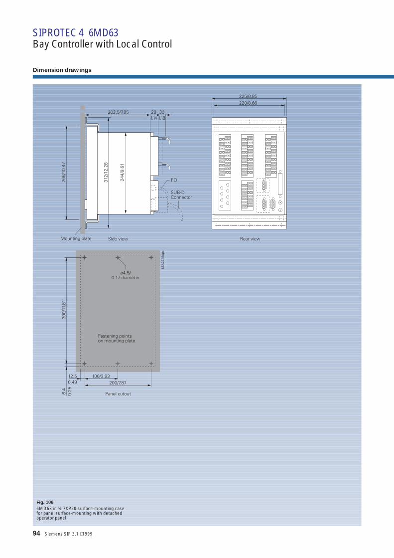
94 Siemens SIP 3.1 ⋅ 1999
Fig. 106
6MD63 in ½ 7XP20 surface-mounting casefor panel surface-mounting with detachedoperator panel
Dimension drawings
SIPROTEC 4 6MD63Bay Controller with Local Control

Siemens SIP 3.1 ⋅ 1999 95Siemens SIP 3.1 ⋅ 1999 95
Fig. 107
6MD63, 7XP20 surface-mounting case, plug-in terminal(installation in LV compartment) only with detached operator panel SIPROTEC 4 6MD63

96 Siemens SIP 3.1 ⋅ 1999
Fig. 108
6MD63 detached operator panel
Dimension drawings
SIPROTEC 4 6MD63Bay Controller with Local Control

Siemens SIP 3.1 ⋅ 1999 97Siemens SIP 3.1 ⋅ 1999 97
ANSINumber
IECDesignation
ANSI Standard 7SJ61/62/63
14 underspeed device. A device that functions when the speed of a machine fallsbelow a predetermined value.
Speed sensor issues a binary signalto a binary input. Function:Starting time supervision
21
FL
distance relay. A relay that functions when the circuit admittance, impedance, or reactanceincreases or decreases beyond a predetermined value.Fault locator Function: Fault locator
25 synchronizing or synchronism-check device. A device that operates when two ACcircuits are within the desired limits of frequency, phase angle and voltage to permitor cause the paralleling of these two circuits.
Function planned
27 U< undervoltage relay. A relay that operates when its input voltage is less than apredetermined value.
Function: Undervoltage
32 directional power relay. A relay that operates on a predetermined value of powerflow in a given direction or upon reverse power flow such as that resulting from themotoring of a generator upon loss of its prime mover.
Function planned
33 position switch. A switch that makes or breaks contact when the main device orpiece of apparatus that has no device function number reaches a given position.
Motor control with 7SJ63 (6MD63)
34 master sequence device. A device such as a motor-operated multicontact switch, or theequivalent, or a programming device, such as a computer, that establishes or determines theoperating sequence of the major devices in equipment during starting and stopping or duringother sequential switching operations.
Application of programmable logic
37 I< undercurrent or underpower relay. A relay that functions when the current or power flowdecreases below a predetermined value.
Application of programmable logicOperating measured value and limitvalue module
46 I2 reverse-phase or phase-balance current relay. A relay that functions when the polyphasecurrents are of reverse-phase sequence or when the polyphase currentsare unbalanced, or contain negative phase-sequence components above a given amount.
Function: Phase balance currentprotection/negative sequence pro-tection
47 phase-sequence or phase-balance voltage relay. A relay that functions upon apredetermined value of polyphase voltage in the desired phase sequence, when thepolyphase voltages are unbalanced, or when the negative phase-sequence voltageexceeds a given amount.
Function: Measured valuemonitoring
48 I start max. incomplete sequence relay. A relay that generally returns the equipment to thenormal, or off, position and locks it out if the normal starting, operating, or stoppingsequence is not properly completed within a predetermined time.
Function: Starting timesupervision
49 ν> machine or transformer thermal relay. A relay that functions when the temperature of amachine armature winding or other load-carrying winding or element of a machine or powertransformer exceeds a predetermined value.
Function: Overload protection
50 I>>, I> instantaneous overcurrent relay. A relay that functions instantaneously on an excessivevalue of current.
Function: Time-overcurrentprotection
NBF Function: Breaker-failure
protection51N
I>>t, I>t, Ip
Ignd>>t,Ignd>t,Igndp
ac time overcurrent relay. A relay that functions when the ac input current exceedsa predetermined value, and in which the input current and operating time are inverselyrelated through a substantial portion of the performance range.
Function: Time-overcurrentprotection
52 ac circuit-breaker. A device that is used to close and interrupt an AC power circuit under nor-mal conditions or to interrupt this circuit under fault or emergency conditions.
55 cos ϕ power factor relay. A relay that operates when the power factor in an AC circuit risesabove or falls below a predetermined value.
Application of programmable logicOperating measured value and limitvalue module
59 U>>t, U>t overvoltage relay. A relay that operates when its input voltage is more than apredetermined value.
Function: Overvoltage
62 time - delayed stopping or opening relay. A time-delay relay that serves in conjunctionwith the device that initiates the shutdown, stopping, or opening operation in an automaticsequence or protective relay system.
Application of programmable logic
64 Ig>t ground detector relay. A relay that operates upon failure of machine or other apparatusinsulation to ground.
Function: Ground fault detection
66 notching or jogging device. A device that functions to allow only a specified number of op-erations of a given device or equipment, or a specified number of successive operations with-in a given time of each other. It is also a device that functions to energize a circuit periodicallyor for fractions of specified time intervals, or that is used to permit intermittent acceleration orjogging of a machine at low speeds for mechanical positioning
Function: Start inhibit
67 Idir.>>t,Idir.>tIdir.p
ac directional overcurrent relay. A relay that functions on a desired value ofAC overcurrent flowing in a predetermined direction.
Function: Directional overcurrent-time protection
N Ignd dir.>>tIgnd dir.>tIgnd dir.p
Ns IEE>>tIEE>t
Function: Ground fault protection
Explanation of ANSI numbers, IEC designation
Appendix

98 Siemens SIP 3.1 ⋅ 1999
ANSINumber
IECDesignation
ANSI Standard 7SJ61/62/63
74TC alarm relay. A relay other than an annunciator, as covered under device function 30,that is used to operate, or that operates in connection with, a visual or audible alarm.
Function: Trip circuit supervision
79 ac reclosing relay. A relay that controls the automatic reclosing and locking out of anAC circuit interrupter.
Function: Auto-reclosure
81O/U frequency relay. A relay that responds to frequency of an electrical quantity,operating when the frequency or rate of change of frequency exceeds or is less thana predetermined value.
Function: Frequency protection
86 lockout relay. A hand or electrically reset auxiliary relay that is operated upon theoccurrence of abnormal conditions to maintain associated equipment or devicesinoperative until it is reset.
Stored relays
87 differential protective relay. A protective relay that functions on a percentage, phase angle,or other quantitative difference between two currents or some other electrical quantities.
Not existingSee transformer differentialprotection 7UT**
Supplements:Function: Dynamic setting groupTime-overcurrent protectionFunction: Making stabilization/inrushrestraint
Explanation of ANSI numbers, IEC designation
Appendix
List of abbreviations used
SCADA Supervisory Control and Data AquisitionSIPROTEC SIEMENS PROTECTIONSICAM Substation Information Control Automation and Monitoring SystemSIMATIC SIEMENS Automation TechnologyPLC Programmable Logic ControlCFC Continuous Function ChartFlash EPROM Electrically Programmable and Erasable MemoryIRIG B Time synchronizing signal via Global Positioning SystemDCF77 Time synchronizing signal in GermanyGPS Global Position SystemLED Light Emitting DiodeUMZ curvesDMT characteristics
Definite-time overcurrent-time relay
AMZ curvesIDMT characteristics
Inverse-time overcurrent protection
ARC Auto-reclosureEF Earth Fault detectionBI Binary InputR RelaySC Substation ControllerFO Fiber Optic ConductorOLM Optical Link ModuleANSI American National Standard InstituteIEC International Electrotechnical CommissionDO Digital OutputBO Binary OutputCB Circuit-Breaker
Current transformer (CT)Voltage transformerRelay contact (normally open)Relay contact (normally closed)

Siemens SIP 3.1 ⋅ 1999 99
Title Designation Order No.
Numerical Protective Relaying
Numerical Protection Devices LSA 2.0.1 E50001-K5702-A011-A1-7600Operation and Evaluation Software for Numerical Protection Devices LSA 2.0.2 E50001-K5702-A121-A1-7600Relay Selection Guide LSA 2.0.3 E50001-K5702-A031-A2-7600SIPROTEC 7SJ600 Overcurrent, Motor and Overload Protection LSA 2.1.15 E50001-K5712-A251-A2-7600SIPROTEC 7SJ601 Overcurrent Protection LSA 2.1.16 E50001-K5712-A261-A1-76007SJ41 Definite-Time Overcurrent Protection Relay LSA 2.1.10 E50001-K5712-A201-A2-76007SJ511 Numerical Overcurrent-Time Protection (Version V3) LSA 2.1.3 E50001-K5712-A131-A2-76007SJ512 Numerical Overcurrent-Time Protection (Version V3) LSA 2.1.4 E50001-K5712-A141-A3-76007SJ512 Numerical Feeder Protection LSA 2.1.30 E50001-K5712-A411-A1-4A00SIPROTEC 7SJ531 Numerical Line and Motor Protection with Control Function LSA 2.1.9 E50001-K5712-A191-A4-76007SJ551 Multi-Function Protection Relay LSA 2.4.2 E50001-K5742-A121-A3-7600SIPROTEC 4 7SJ61/62/63 6MD63 Multifunction Protection Ralay and Bay Controller SIP 3.1 E50001-K4403-A111-A1-4A00SIPROTEC 7SA510 Distance Protection Relay (Version V3) LSA 2.1.17 E50001-K5712-A271-A1-7600SIPROTEC 7SA511 Distance Protection Relay (Version V3) LSA 2.1.11 E50001-K5712-A211-A2-76007SA513 Line Protection Relay (Version V3) LSA 2.1.12 E50001-K5712-A221-A1-76007SA518/519 Overhead Control-Line Protection Relay (Version V3) LSA 2.1.14 E50001-K5712-A241-A2-76003VU13 Miniature Circuit-Breaker LSA 2.1.8 E50001-K5712-A181-A2-76007SD502 Line Differential Protection with Two Pilot Wires LSA 2.2.1 E50001-K5722-A111-A2-76007SD503 Line Differential Protection with Three Pilot Wires LSA 2.2.2 E50001-K5722-A121-A2-76007SD511/512 Current Comparison Protection Relay (Version V3)for Overhead Lines and Cables LSA 2.2.3 E50001-K5722-A131-A2-7600SIPROTEC 7SD60 Numerical Current Differential Protection for two Pilot-Wire Link SIPROTEC 5.2 E50001-K4405-A121-A1-76007UT512/513 Differential Protection Relay (Version V3)for Transformers, Generators and Motors LSA 2.2.4 E50001-K5722-A141-A2-7600SIPROTEC 7RW600 Numerical Voltage, Frequency andOverexcitation Relay LSA 2.7.10 E50001-K5772-A201-A1-76007SS5 Station Protection SIPROTEC 5.1 E50001-K4405-A151-A2-7600SIPROTEC 7SS52 Distributed Numerical Busbar and Circuit-BreakerFailure Protection Relay LSA 2.2.7 E50001-K5722-A171-A1-7600Auxiliary Current Transformers 4AM50, 4AM51, 4AM52and Isolating Transformers 7XR95 LSA 2.2.6 E50001-K5722-A161-A1-7600Introduction to Earth-Fault Detection LSA 2.3.1 E50001-K5732-A111-A2-76007SN71 Transient Earth-Fault Relay LSA 2.3.2 E50001-K5732-A121-A1-76007XR96 Toroidal Current Transformer LSA 2.3.3 E50001-K5732-A131-A1-76007VC1637 Earth-Leakage Monitor LSA 2.3.4 E50001-K5732-A141-A1-76007SK52 Motor Protection LSA 2.4.1 E50001-K5742-A111-A1-7600Introduction to Generator Protection LSA 2.5.1 E50001-K5752-A111-A1-76007UM511 Generator Protection Relay (Version V3) LSA 2.5.2 E50001-K5752-A121-A2-76007UM512 Generator Protection Relay (Version V3) LSA 2.5.3 E50001-K5752-A131-A2-76007UM515 Generator Protection Relay (Version V3) LSA 2.5.4 E50001-K5752-A141-A2-76007UM516 Generator Protection Relay (Version V3) LSA 2.5.5 E50001-K5752-A151-A1-76007UW50 Tripping Matrix LSA 2.5.6 E50001-K5752-A161-A1-76007VE51 Synchronizing Unit LSA 2.5.7 E50001-K5752-A171-A1-76007VP151 Three-Phase Portable Test Set (Omicron CMC56) LSA 2.6.1 E50001-K5762-A111-A2-76007XV72 Test Switch LSA 2.6.2 E50001-K5762-A121-A1-76007SV50 Numerical Circuit-Breaker Failure Protection Relay LSA 2.7.1 E50001-K5772-A111-A1-76007SV512 Numerical Circuit-Breaker Failure Protection Relay LSA 2.7.2 E50001-K5772-A121-A1-76007VK512 Numerical Auto-Reclose/Check-Synchronism Relay LSA 2.7.3 E50001-K5772-A131-A1-76007SM70 Analog Output Unit LSA 2.7.5 E50001-K5772-A151-A1-76007SM71 Analog Output Unit LSA 2.7.6 E50001-K5772-A161-A1-76007SV7220 Power Supply Unit LSA 2.7.9 E50001-K5772-A191-A1-7600Communication for Protection DevicesCentralized and Remote Control of Siemens Protection Relays (Overview) SIPROTEC 8.1 E50001-K4408-A111-A1-7600Operating and Analysis Software DIGSI V3 LSA 2.8.2 E50001-K5782-A121-A1-7600
Analog Protective Relaying
Static Analog Network Protection Relays R 1.1 E50001-K4501-A111-A1-7600Static Analog Machine Protection Relays R 1.2 E50001-K4501-A121-A1-7600Static Analog Ancillary Protection Equipment R 1.3 E50001-K4501-A131-A1-7600
Energy Automation
Substation SICAM RTU System SICAM 2.1.1 E50001-K5602-A111-A1-7600SICAM micro RTU 6MD2030 Substation SICAM 2.3.1 E50001-K5602-A311-A1-7600PS20A-6EP8090 Power Supply Module SICAM 5.1.1 E50001-K5605-A111-A1-7600DI32-6MD1021 Digital Input Functional Module SICAM 5.2.1 E50001-K5605-A211-A1-7600AI32-6MD1031 Analog Input Functional Module SICAM 5.2.2 E50001-K5605-A221-A1-7600AI16-6MD1032 Analog Input Functional Module SICAM 5.2.3 E50001-K5605-A231-A1-7600CO32-6MD1022 Command Output Functional Module SICAM 5.3.1 E50001-K5605-A311-A1-7600CR-6MD1023 Command Release Functional Module SICAM 5.3.2 E50001-K5605-A321-A1-7600
Power Quality
Fault Recorder OSCILLOSTORE SR 10.1 E50001-K4010-A101-A1-7600Fault and Digital Recorder SIMEAS R SR 10.1.1 E50001-K4011-A101-A1-7600Central Fault Data Unit DAKON SR 10.1.2 see IntranetOSCOP P The Program for Quality Recorders SR 10.1.3 E50001-K4013-A101-A1-7600Power System Quality Analysis OSCILLOSTORE SR 10.2 E50001-K4020-A101-A1-7600SIMEAS Q Quality Recorder SR 10.2.5 E50001-K4025-A101-A1-7600SIMEAS P Power Meter SR 10.2.6 E50001-K4026-A101-A1-7600Active Filter and Power Conditioner for Distributed Networks SIPCON P/S SR 10.5 E50001-K4050-A201-A1-7600Low Voltage Capacitors and Power Factor Correction Units SIPCON T SR 10.6 E50001-K4060-A101-A1-7600SIMEAS T Transducer for Power Variables SR 10.4 E50001-K4040-A101-A1-7600
Catalog Index of the Power Transmission and Distribution Group (Protection and Substation Control Systems Division)

100 Siemens SIP 3.1 ⋅ 1999
Siemens Companies and Representatives Power Transmission and Distribution Group
Appendix
Europe
AustriaSiemens AG ÖsterreichSiemensstr. 88 - 92A-1211 WienMrs. StrobachPhone: +43-1-1707-22522Fax: +43-1-1707-53075
BelgiumSiemens S. A.Chaussée de Charlerois 116B-1060 BrüsselMr. BelvauxPhone: +32-2-53621-2595Fax: +32-2-53621-6900
Czech. RepublicSiemens s. r. o.Na Strzi 40CZ-140 00 Prag 4Mr. SlechtaPhone: +420-2-61095209Fax: +420-2-61095252
DenmarkSiemens A / SBorupvang 3DK-2750 BallerupMr. JensenPhone: +45-4477 4309Fax: +45-4477 4020
FinlandSiemens OsakeyhtiöMajurinkatu 1FIN-02601 EspooMr. TuukkanenPhone: +358-9-5105 3846Fax: +358-9-5105 3530
FranceSiemens S. A.39-47, boulevard OrnanoF 93527 Saint DenisMr. CieslakPhone: +33-1-4922 3469Fax: +33-1-4922 3090
GreeceSiemens A. E.Artemidos 8GR-151 10 AthenMr. RoubisPhone: +30-1-6864530Fax: +30-1-6864703
ItalySiemens S.p. A.Via Fabio Filzi 29I-20 124 MailandMr. MormilePhone: +39-2-66762854Fax: +39-2-66762347
IrelandSiemens Ltd.8 Raglan RoadBallsbridgeDublin 4Mr. KernanPhone: +353-1-603 2430Fax: +353-1-603 2499
NetherlandsSiemens Nederland N.V.Prinses Beatrixlaan 26NL-2500 BB Den HaagMr. LangedijkPhone: +31-70-333 3126Fax: +31-70-333 3225
NorwaySiemens A / SOstre Aker vei 90N-0518 OsloMr. GravermoenPhone: +47-22-633140Fax: +47-22-633796
PolandSiemens Sp.z.o.o.ul. Zupnicza 11PL-03-821 WarschauMr. DombrowskiPhone: +48-22-8709120Fax: +48-22-8709139
PortugalSiemens S. A..Apartado 60300P-2700 AmadoraMr. PissarroPhone: +351-1-417 8253Fax: +351-1-417 8071
SloveniaBranch office: SiemensAustria
SpainSiemens S.A.Apartado 155E 28 020 MadridMr. MartinPhone: +34-1-5147562Fax: +34-1-5147037
SwitzerlandSiemens-Albis AGFreilagerstr. 28 - 40CH-8047 ZürichMr. HorisbergerPhone: +41-1-495-3566Fax: +41-1-495-3253
TurkeySIMKO Ticaret ve Sanayi ASMeclisi Mebusan Caddesi12580040 Findikli-IstanbulMr. UzunerPhone: +90-0216-4593741Fax: +90-0216-4592155
United KingdomSiemens plcSir William Siemens HousePrincess RoadManchester M20 2URMr. DenningPhone: +44-1-614465130Fax: +44-1-614465105
Africa
EgyptSiemens Ltd.Cairo, P.O.Box 775 / 1151126, El Batal AhmedAbdel Aziz Str.MohandessinMr. Aly Abou-ZiedPhone: +20-2-3499727,Fax: +20-2-3446774
South AfricaSiemens Ltd., PT & D26 Electron Ave.,Isando 1600Mr. A MatthePhone: +27-11-921 2499Fax: +27-11-921 7100
Australia
Siemens Ltd., PT & DSydney Office383 Pacific HighwayArtarmon N.S.W. 2064Mr. FominPhone: +61-2-9950 8649Fax: +61-2-9950 8733
North America
USASiemensPower Transmission &Distribution, LLC7000 Siemens Rd.Wendell , NC 27591Mr. C. PretoriusPhone: +1-919-365 2196Fax: +1-919-365 2552
Mexico
Siemens S.A. DE C.V.Pte. 116 No. 590,Col. Ind. Vallejo02300 Mexico D.F.Mr. LoredoPhone: +52-5-3282012Fax: +52-5-3282241
South America
BrazilSiemens S.A.Coronel Bento Bicudo,111 Lapa05069-900 Sao Paulo -SPMr. MuramotoPhone: +55-11-833 4079Fax: +55-11-833 4391
ColumbiaSiemens S.A., GDHSantafe de Bogota,D.C.Cra 65 No. 11-83ConmutaMr. Walter Bing-ZarembaPhone: +57-1-294 2222Fax: +57-1-294 2500
Asia
ChinaSiemens Ltd., PT & DNo. 7, Wangjing ZhonghuanNanlu, Chaoyang DistrictBeijing, 100015Mr. Sure En LeePhone: +86-10-6436 1888
ext. 3806Fax: +86-10-64356729
Hong KongSiemens Ltd., PTD58/F Central Plaza18 Harbour RoadWanchai, Hong KongMr. Humphrey S.K. LingPhone: +852-2583 3388Fax: +852-28029903
IndiaSiemens Ltd., PTD / ZLS4A, Ring Road, I.P. EstateNew Delhi 110 002Mr. A. K. DixitPhone: +91-11-3719877Fax: +91-11-3739161
IndonesiaP.T. Siemens IndonesiaJl. Jend. A. YaniPulo Mas, Jakarta 13210P.O.Box 2469Jakarta 10001Mr. Volker SchenkPhone: +62-21-4729 153Fax: +62-21-471 5055,
472 9201
MalaysiaSiemens Regional Office12th. flr., Menara Choy Fook OnNo 1B, Jalan Yong Shook Lin46050 Petaling JayaSelangor Darul EhsanMr. VindPhone: +60-3-751 3923
(direct)Phone: +60-3-755 1133
(switchb.)Fax: +60-3-757 0380
PhilippinesSiemens Inc.14 F Centerpoint Bldg.Orligas Center, Pasig CityMakati 1229, Metro ManilaMr. De GuzmannPhone.: +63-2-637 0900Fax: +63-2-633 5592
SingaporePower Automation89 Science Park, #04-13The Rutherford,Singapore 112861Mr. AuPhone.: +65-872 2688Fax: +65-872 3692
TaiwanSiemens Ltd., PT & D Dept.19th Floor, 333, Tun-Hua S.Road,Sec. 2, (P.O.Box 26-755)TaipeiMr. Frances PengPhone.: +886-2-2378 8900
ext. 832Fax: +886-2-2378 8958
ThailandSiemens Limited EV SP Dept.Charn Issara Tower II,32ndFloor2922/283 New Petchburi RoadBangkapi, HuaykwangBangkok 10320Mr. Chaturawit S.Phone.: +66-2-715-4815Fax: +66-2-715-4785
VietnamSiemens AG,Representation58 Ton Duc Thong St.District 1Ho Chi Minh CityMrs. HungPhone.: +84-8825 1900Fax: +84-8825 1580
Responsible forTechnical contents: Hans Heining-TriebsSiemens AG, EV S V13, NürnbergGeneral editing: Claudia Kühn-SutionoSiemens AG, EV BK T, Erlangen
Order No.: E50001-K4403-A111-A1-4A00
Printed in GermanyKGK 0899 5.0 100 En 100280 6101/709

Conditions of Sale and Delivery
Subject to theGeneral Conditions of Supplyand Delivery for Products andServices of the Electrical andElectronic Industry and to anyother conditions agreed uponwith the recipients of cata-logs.
n
The technical data, dimen-sions and weights are subjectto change unless otherwisestated on the individual pagesof this catalog.The illustrations are for refer-ence only.We reserve the right to adjustthe prices and shall chargethe price applying on the dateof delivery
Export Regulations
In accordance with the pres-ent provisions of the GermanExport List and the US Com-mercial Control List, exportlicences are not required forthe products listed in this cata-log.
AL: NECCN: EAR99
An export licence may how-ever be required due to countryspecific application and finaldestination of the products.Relevant are the export crite-ria stated in the delivery noteand the invoice regarding apossible export and reexportlicence.
Subject to change without no-tice.
Trademarks Dimensions
All product designations usedare trademarks or productnames of Siemens AG or ofother suppliers.
All dimensions in this catalogare given in mm/inch.
Appendix

BereichEnergieübertragung und -verteilungGeschäftsgebiet SekundärsystemePostfach 4806D-90026 Nürnberghttp://www.ev.siemens.de
Siemens Aktiengesellschaft Order No.: E50001-K4403-A111-A1-4A00