8 royale manual
DESCRIPTION
ÂTRANSCRIPT
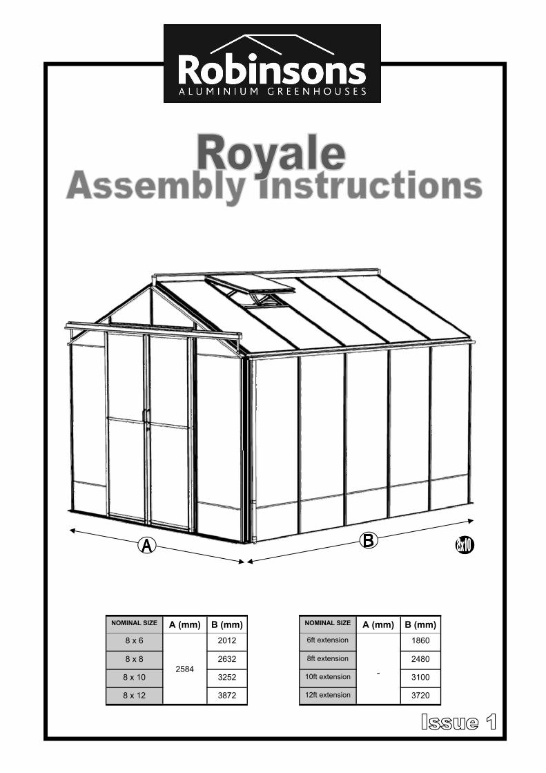
NOMINAL SIZE A (mm) B (mm)
8 x 6
2584
2012
8 x 8 2632
8 x 10 3252
8 x 12 3872
NOMINAL SIZE A (mm) B (mm)
6ft extension -
1860
8ft extension 2480
10ft extension 3100
12ft extension 3720
2
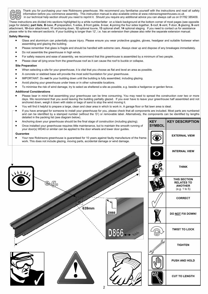
Thank you for purchasing your new Robinsons greenhouse. We recommend you familiarise yourself with the instructions and read all safety information before you commence assembly. This instruction manual is also available online at www.robinsonsgreenhouses.co.uk in our technical help section should you need to reprint it. Should you require any additional advice you can always call us on 01782 385409.
These instructions are divided into sections highlighted by a white number/letter on a black background at the bottom corner of most pages (see opposite page for details); part lists, B-base, P-preparation, 1-sides, 2-front gable, 3-rear, 4-joining the four sides together, 5-roof, 6-vent, 7-door, 8-glazing, 9-vent attachment, 10-door attachment, 11 anchoring down, 12 optional louvre, 13 optional shelf, 14 optional staging. If you need to contact us for assistance please refer to the relevant section/s. If your building is longer than 12’, i.e. has an extension then please also refer the separate extension manual.
Safety Warning
Glass and aluminium can potentially cause injury. Please ensure you wear protective goggles, gloves, headgear and suitable footwear when assembling and glazing the building.
Please remember that glass is fragile and should be handled with extreme care. Always clear up and dispose of any breakages immediately.
Do not assemble the greenhouse in high winds.
For safety reasons and ease of assembly, we recommend that this greenhouse is assembled by a minimum of two people.
Please clear all lying snow from the greenhouse roof as it can cause the roof to buckle or collapse. Site Preparation
When selecting a site for your greenhouse, it is vital that you choose as flat and level an area as possible.
A concrete or slabbed base will provide the most solid foundation for your greenhouse.
IMPORTANT: Do not fix your building down until the building is fully assembled, including glazing.
Avoid placing your greenhouse under trees or in other vulnerable locations.
To minimise the risk of wind damage, try to select as sheltered a site as possible, e.g. beside a hedgerow or garden fence. Additional Considerations
Please bear in mind that assembling your greenhouse can be time consuming. You may need to spread the construction over two or more days. We recommend that you avoid leaving the building partially glazed. If you ever have to leave your greenhouse half assembled and not anchored down, weigh it down with slabs or bags of sand to stop the wind moving it.
You will find it helpful to prepare a large, clean and clear area in which to work in. A garage floor or flat lawn area is ideal.
If you have arranged for someone to install your greenhouse for you, please check that all components are included. Most parts are numbered and can be identified by a stamped number (without the ’D’) or removable label. Alternatively, the components can be identified by lengths detailed in the packing list (see diagram below).
Anchoring down your greenhouse should be the final stage of construction (including glazing).
Once installed your greenhouse requires little maintenance, but to maintain the smooth running of your door(s) WD40 or similar can be applied to the door wheels and lower door guides.
Guarantee
Your new Robinsons greenhouse is guaranteed for 10 years against faulty manufacture of the frame-work. This does not include glazing, moving parts, accidental damage or wind damage.
KEY SYMBOL
KEY DESCRIPTION
EXTERNAL VIEW
THINK
THIS SECTION RELATES TO
ANOTHER (e.g. 1 to 5)
CORRECT
DO NOT FIX DOWN!
TWIST TO LOCK
TIGHTEN
PUSH AND HOLD
CUT TO LENGTH
INTERNAL VIEW
639mm D866

3
SECTION No TITLE ASSEMBLY SYNOPSIS: IMPORTANT INFORMATION / CONSIDERATIONS
PARTS LIST
Most components should have a ‘D’ code punched into their metal surface. Identify and sepa-rate all like for like components prior to assembly. The ‘parts list’ also separates parts into the various sections 1 - 12 shown below. Parts can also be identified by their profile pictures and stated lengths etc..
B BASE
Base dimensions and recommendations. Ensure that your base is level as this will make as-sembly of the building, especially the glazing of the roof much more straight forward.
P PREPARATION Tools required. IMPORTANT: Use WD40 or similar in the glazing bar channels and insert the black glazing rubber prior to frame assembly.
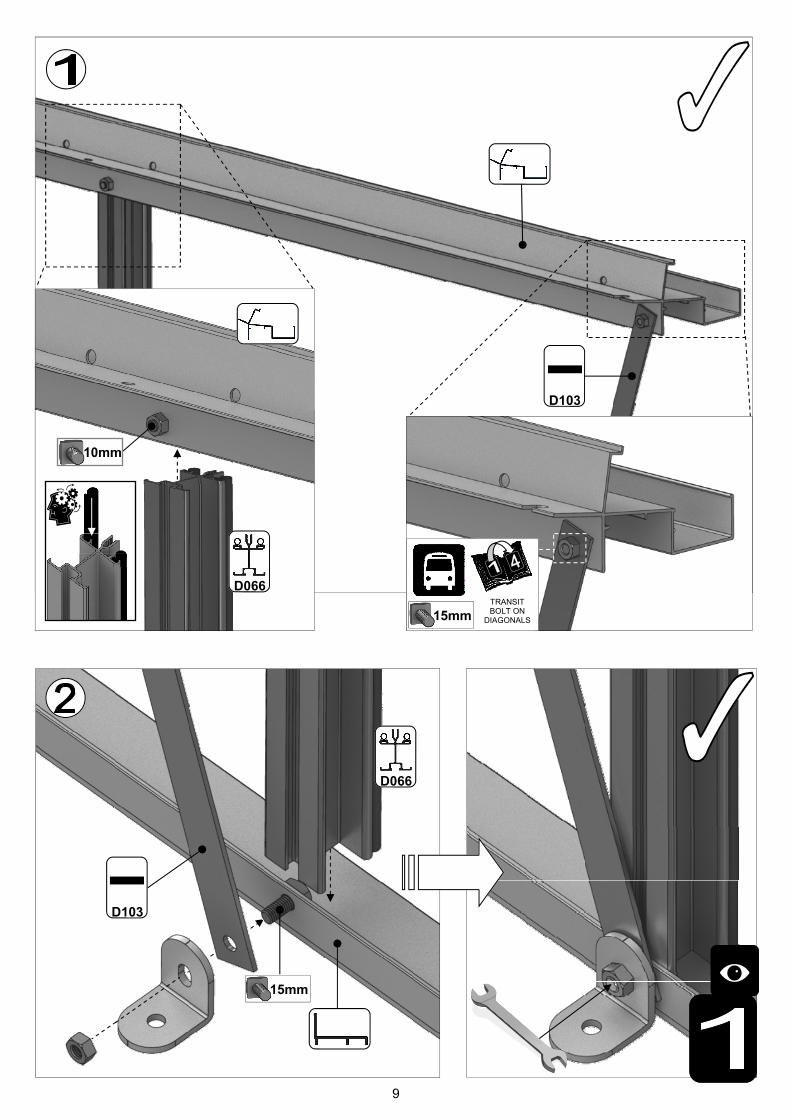
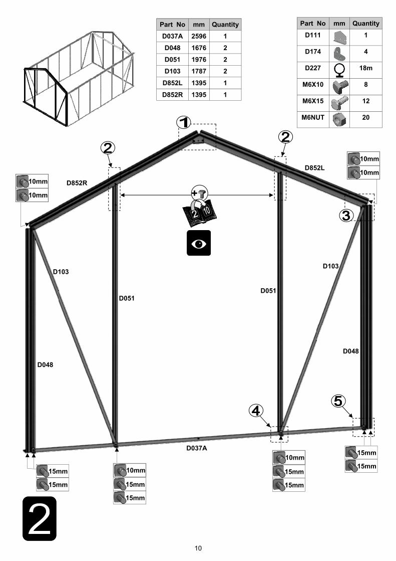
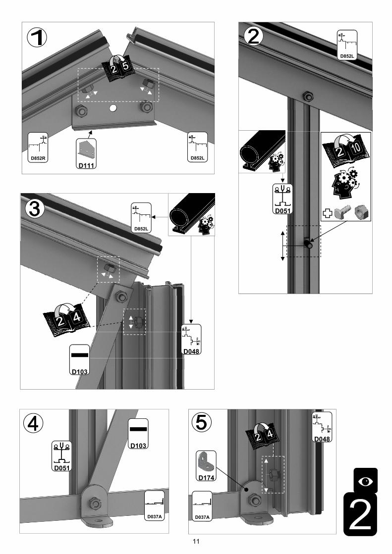
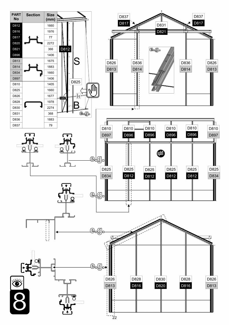
1 SIDES
Take the side glazing bars ‘D066’ with the rubber inserted and the diagonal braces ‘D103’, use 10mm bolts to join them to the gutter and 15mm bolts to the cills (note how the head of the bolt slides into each glazing bar during construction).
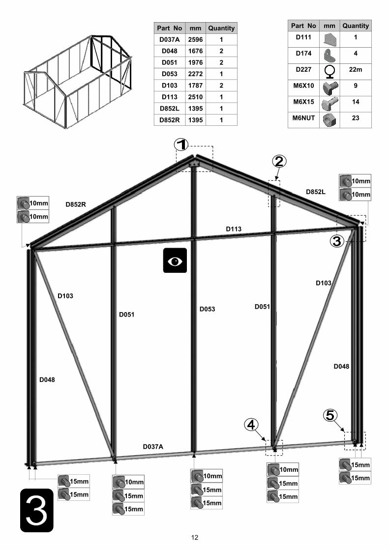
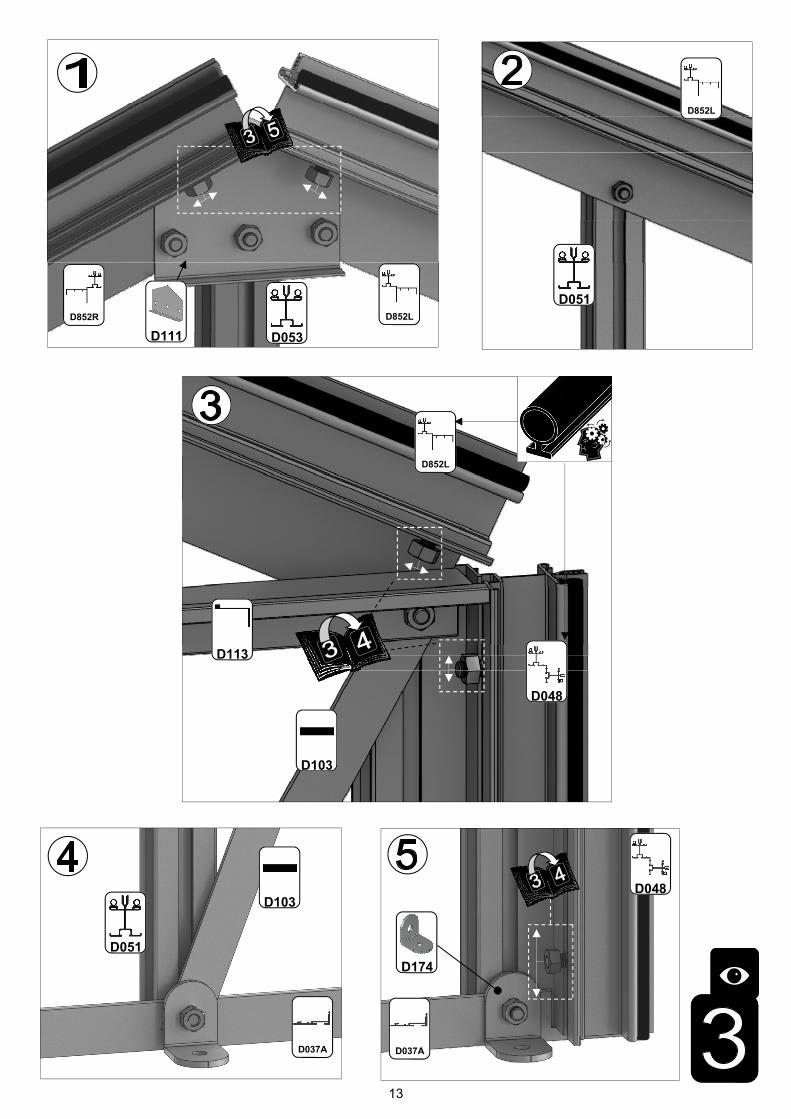
2 FRONT Again insuring that the gable framework is rubbered-up follow the diagrams to assemble each end of the building. Make sure that you have inserted the extra bolts utilised in sections 4, 5 and 10. On the roof and side corner bars not every rubber channel will require rubber unless it is to be utilised in a partition (see separate manual and section P). 3 REAR
4 JOINING THE FOUR SIDES
Take the two sides (1) and both gables (2 & 3) and join them together on your base. It is a good idea to tie some ladders to the sides to support them if you do not have anyone to hold them for you.
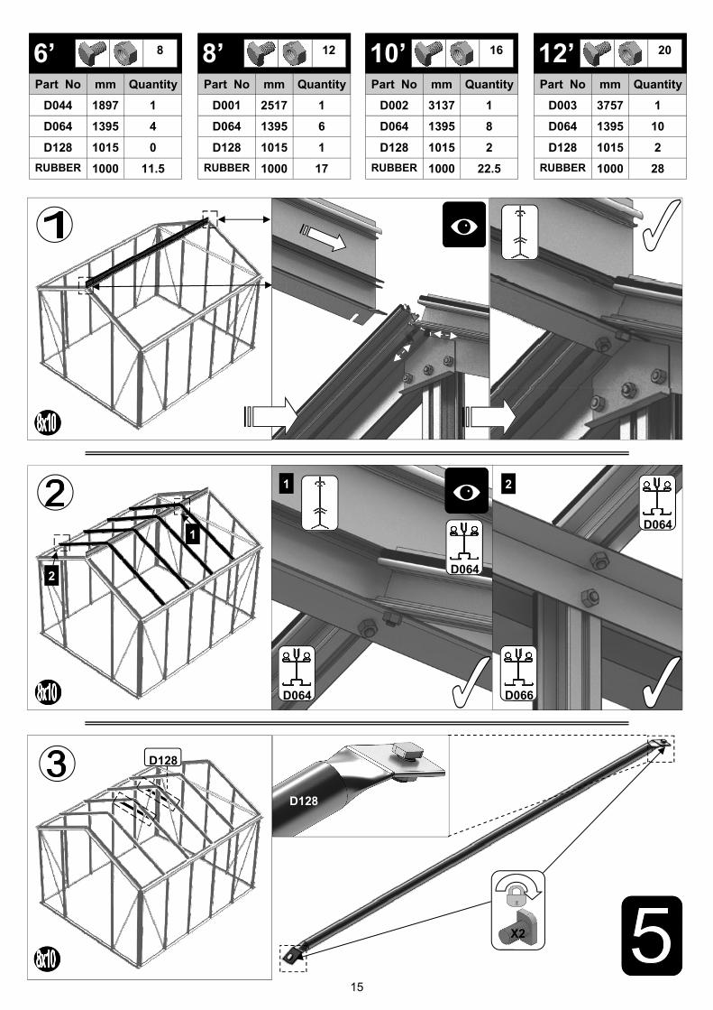
5 ROOF Attach ridge and then the rubbered-up roof bars ensuring that they are fully butted up to the ridge and down onto the gutter. If you have cresting then it is a good idea to fit it before glaz-ing, see section (15). Some tubular braces are supplied to add extra strength, they can be fitted now or later with crop head bolts.
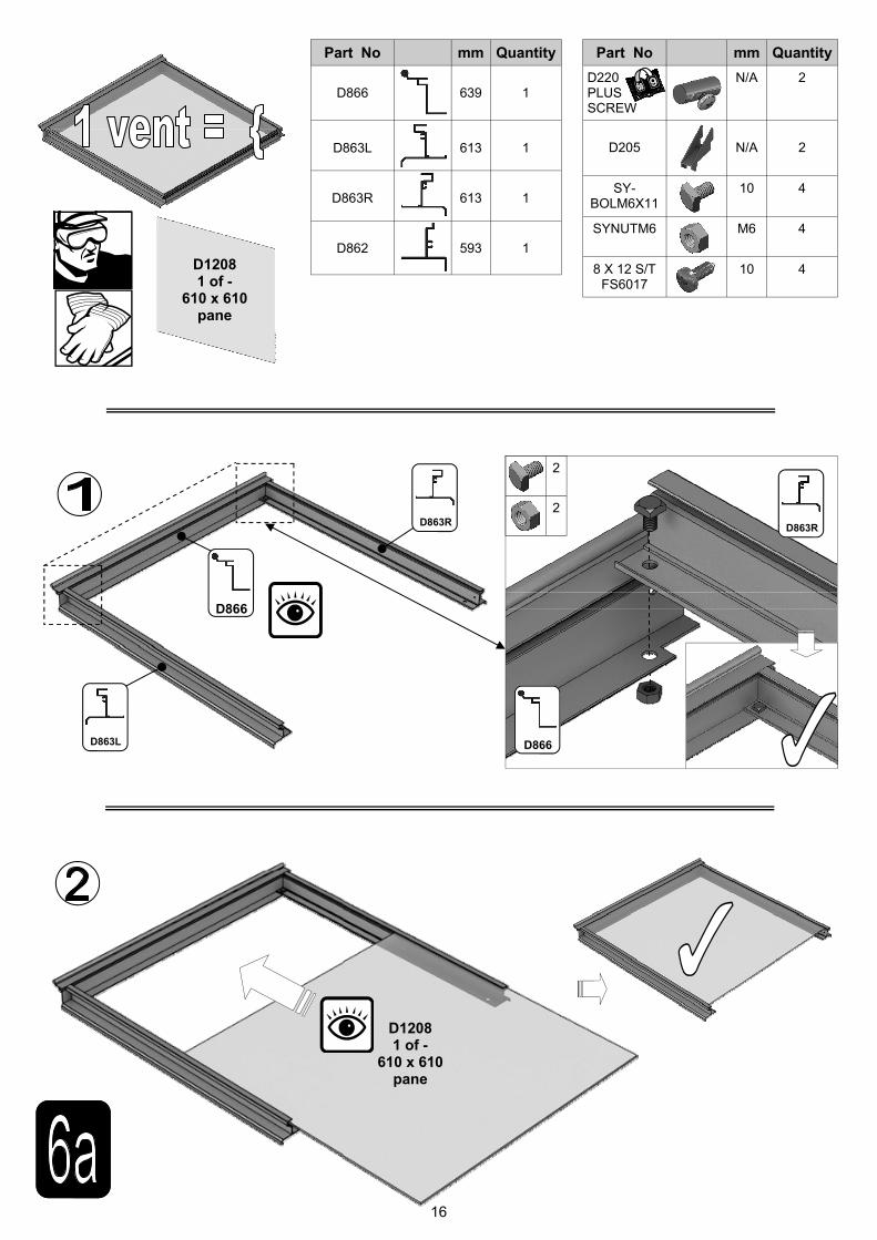
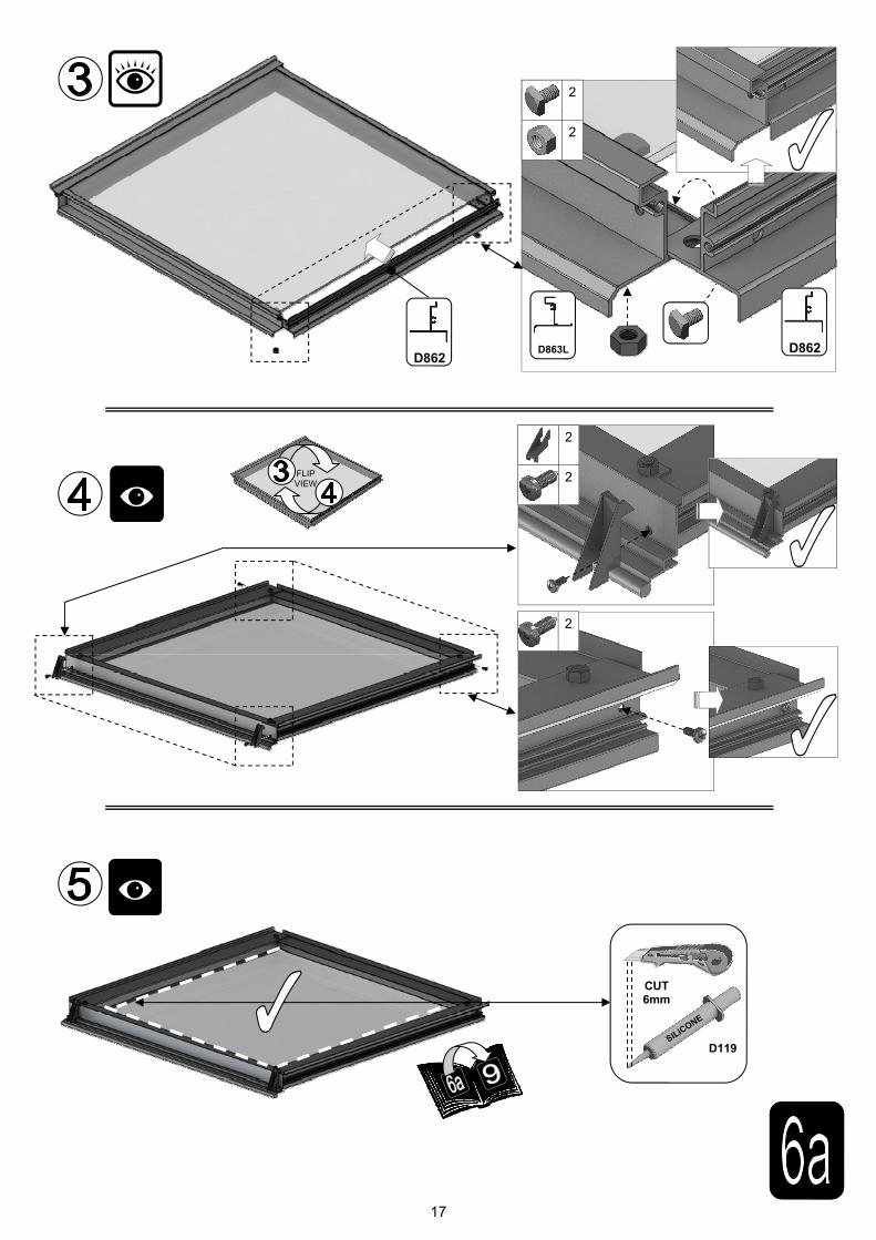
6a VENT Once the vent is glazed add silicone to the vent sides and top. Stand the vent/s on their hinge (vent top) and then leave the silicone to set.
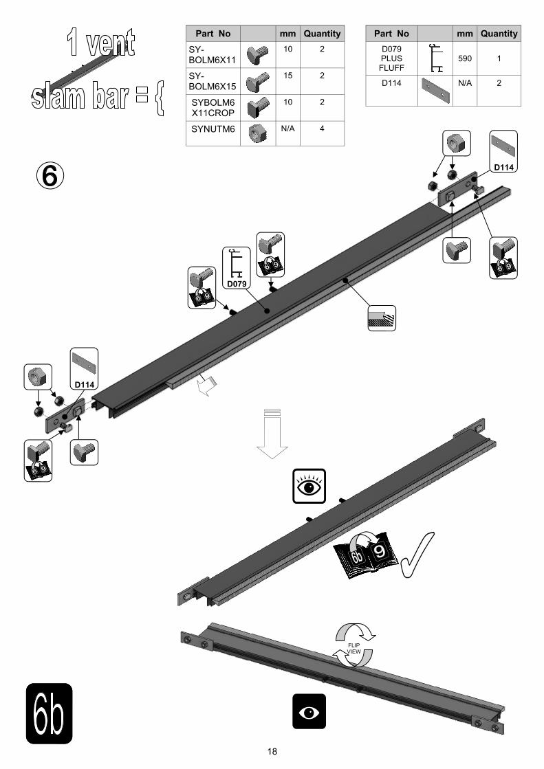
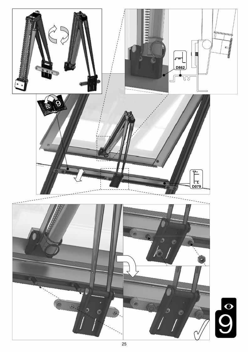
6b VENT SLAM The slam bar ‘D079’ can be moved up and down between the roof glazing bars so that it can be butted down onto the pane of glass beneath, the autovent will be attached to it later on (9).
7 DOOR/S Construct the door using the diagrams and then leave to one side ready for attachment in section (10).
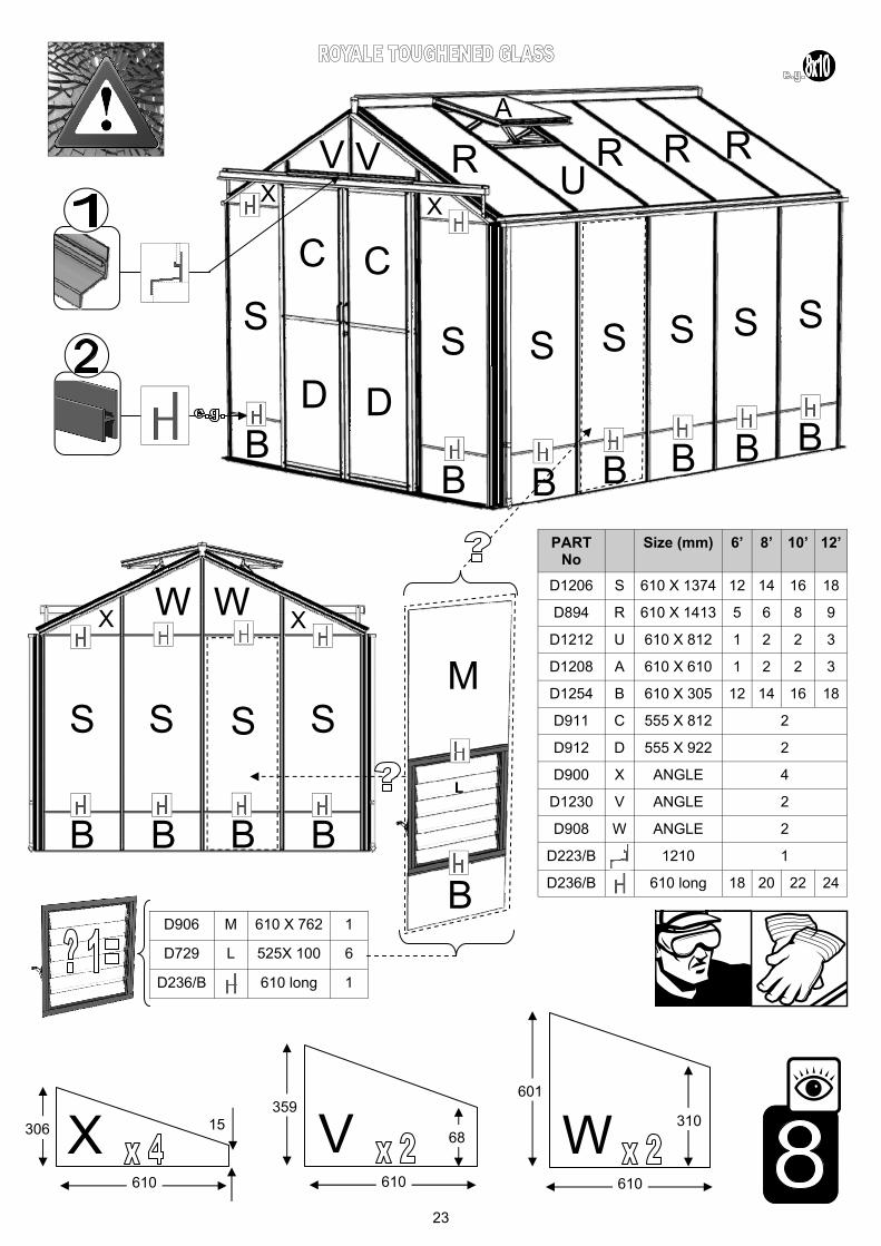
8
GLAZING
Layout the bar cappings and covers around the building like a sundial checking that all is pre-sent and correct. You can also place the roof cappings in the gutters so they are closer to hand. The glass in the sides has to bevel on the black separator strip which is on top of the 305mm high glass base panels. This bevelling action allows the glass to tuck underneath the gutter canopy. Use the capping and the self tapping screws to then hold the glass in place. The covers then enclose the screw heads giving a neat finish.
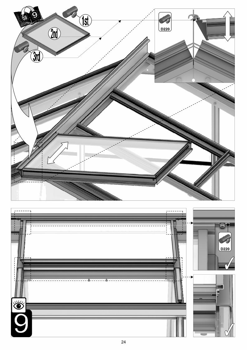
9 VENT ATTACHMENT
Take the assembled vent and slide the vent hinge ‘D866’ into the end of the ridge allowing the vent the pivot open and closed. Vent stops go either side of the vent to stop any lateral move-ment (so insert stop / vent / stop). Attachment of the Bayliss XL autovents.
10 DOOR ATTACHMENT
Utilise the bolts inserted in section (2) to attach the upper door track. The lower door runner ’D861’ and ramp threshold ‘D088’ push down and lock together.
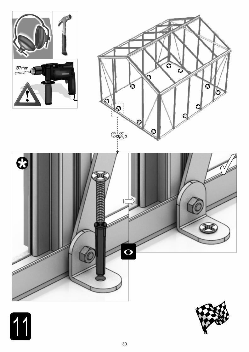
11 ANCHORING DOWN
Now that the greenhouse is finished and the door and vent/s are operating without interfer-ence then you need to anchor the building down using 2” rawl plugs and screws. Use a 7mm masonry bit in a hammer drill to create the holes.
12 OPTIONAL LOUVRE
They attach to the building during the glazing process (8) like a piece of glass with a black separator above and below them.
13 OPTIONAL SHELVING
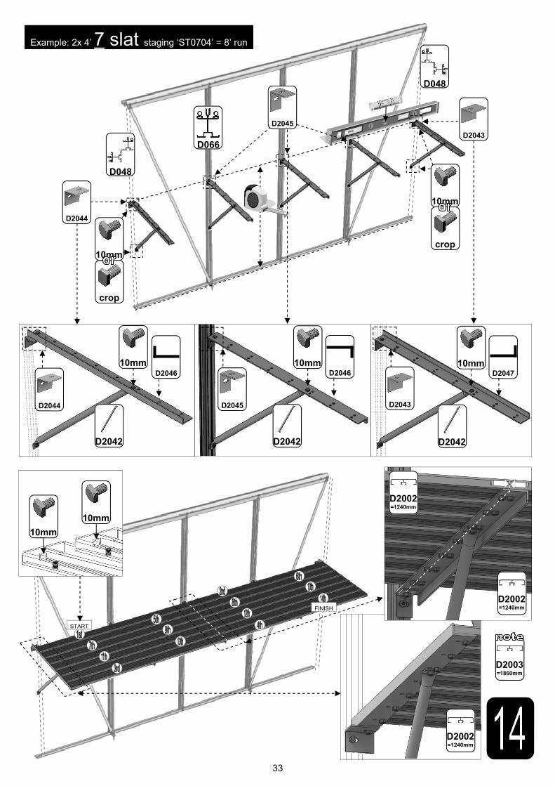
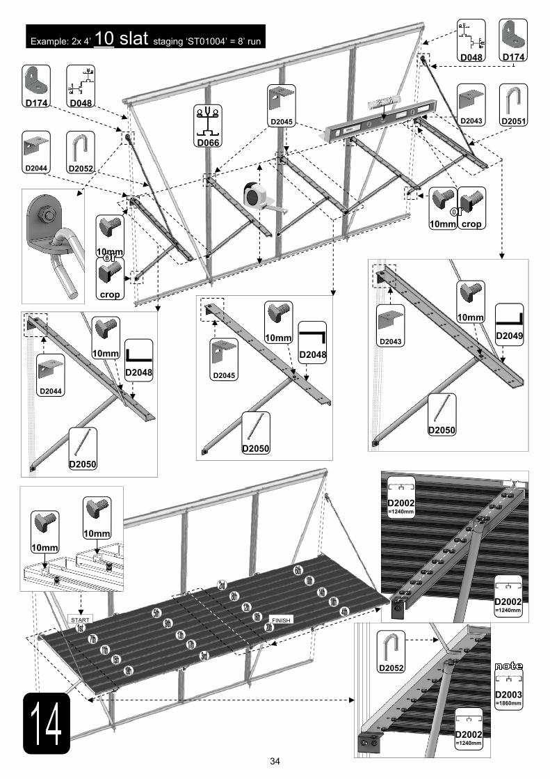
14 OPTIONAL STAGING
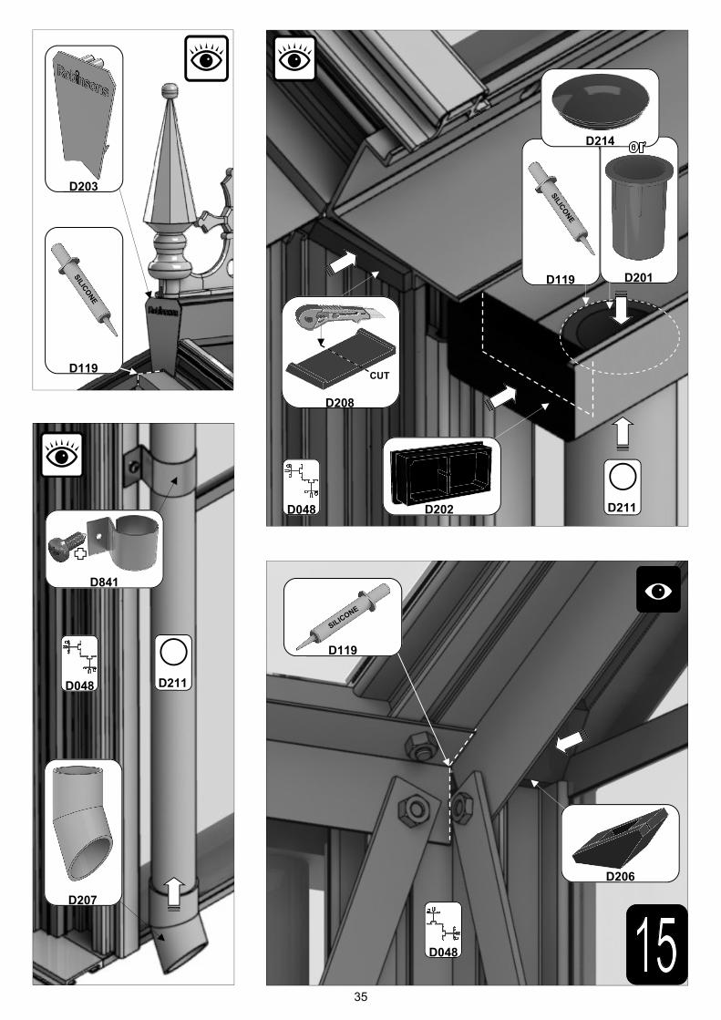
15 FINISHING TOUCHES
Now that the main body of the structure is complete you can add; ridge caps, downpipe fit-tings, eave bungs. Images showing cresting and finial attachment, this is often easiest to do after section (5) rather than using the vent apertures later on (i.e. before glazing).
Robinsons integral cantilever staging and shelving attaches to the inside of the greenhouse frame using either square head bolts (insert four into each side glazing bar ’D066’ during con-struction of the sides (1)) or rectangular ‘crop head’ bolts which can be fitted retrospectively (both sets of bolts accompany the shelving/staging). This system allows the height of either the staging or the shelf to be set at an operator specific height. Commonly the staging brack-ets are set 900mm from the cills though you can alter this to suit the end user/s. The alumin-ium shelf / staging slats come in two lengths; (4’):1240mm ‘D2002’ and (6’):1860mm ’D2003’. These slats can combine to create any length of staging required, i.e. 4’+6’ = 10’ etc...

4
Section Ref
Part No.
Section Size (mm)
8 6
8 8
8 10
8 12
Section Ref
Part No.
Section Size (mm)
8 6
8 8
8 10
8 12
D043 1894 2
D021 2514 2
D022 3134 2
D023 3754 2
D042 1897 2
D014 2517 2
D015 3137 2
D016 3757 2
D103 1787 4
D066
1676
4
6
8
10
RUBBER
1000 (1m)
14
21
27
34
D174
N/A
4
4
8
8
D044 1897 1
D001 2517 1
D002 3137 1
D003 3757 1
D064
1395
4
6
8
10
RUBBER
1000 (1m)
11.5
17
22.5
28
D866
639
1
2
2
3
D863L
613
1
2
2
3
D863R
613
1
2
2
3
D862
593
1
2
2
3
D079
PLUS FLUFF
590
1
2
2
3
D114
N/A
2
4
4
6
D220
PLUS SCREW
N/A
2
4
4
6
D205
N/A
2
4
4
6
D037A
2596
2
D048
1676
4
D051
1976
4
D053
2272
1
D113
2510
1
D103 1787 4
D111
N/A
2
D852L
1395
2
D852R
1395
2
RUBBER
1000 (1m)
38
D174
N/A
8

5
Section Ref
Part No.
Section Size (mm)
8 6
8 8
8 10
8 12
D090 +
D347 lock =
D301
1824
1
D092 +
D156 strike =
D303
1824
1
D093
1824
1
D094
1824
1
D096 +
D217 wheel =
D307
611
2
D095
611
2
D097
611
2
D232 905 4
D233 797 4
P053
N/A
2
D225
610
2
D840B
4000
1
Section Ref
Part No.
Section Size (mm)
8 6
8 8
8 10
8 12
1 D812 1660 4 6 8 10
3 D816 1976 2
2 D817 77 2
5 D896 1406 4 6 8 10
3 D820 2272 1
2 D821 366 1
2/3 D813 1675 4
2 D814 1883 2
1 D834 1660 4
5 D897 1406 4
5 D810 1405 8 10 12 14
1 D825 1660 8 10 12 14
2/3 D826 1677 4
3 D828 1978 2
2 D836 1883 2
2 D837 79 2
3 D830 2274 1
2 D831 368 1
D861
2450
D088
1207
1
D086
2510
1
D085
2510
1
D153 198 2
1
D163 90 2
D150 N/A 1
D154 N/A 2
D865
1210
1
D052
372
1
10mm
29
35
41
15mm
34
36
38
m6
63
71
79
47
40
87
MA
IN F
RA
ME
QU
AN
TIT
IES
VE
NT
S /
DO
OR
S e
tc S
EP
ER
AT
E
6
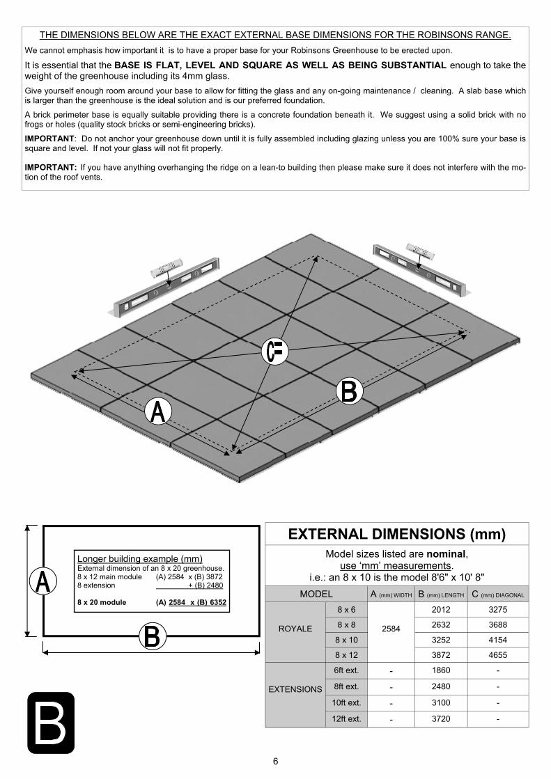
EXTERNAL DIMENSIONS (mm) Model sizes listed are nominal,
use ‘mm’ measurements. i.e.: an 8 x 10 is the model 8'6" x 10' 8"
MODEL A (mm) WIDTH B (mm) LENGTH C (mm) DIAGONAL
ROYALE
8 x 6
2584
2012 3275
8 x 8 2632 3688
8 x 10 3252 4154
8 x 12 3872 4655
EXTENSIONS
6ft ext. - 1860 -
8ft ext. - 2480 -
10ft ext. - 3100 -
12ft ext. - 3720 -
THE DIMENSIONS BELOW ARE THE EXACT EXTERNAL BASE DIMENSIONS FOR THE ROBINSONS RANGE. We cannot emphasis how important it is to have a proper base for your Robinsons Greenhouse to be erected upon. It is essential that the BASE IS FLAT, LEVEL AND SQUARE AS WELL AS BEING SUBSTANTIAL enough to take the weight of the greenhouse including its 4mm glass. Give yourself enough room around your base to allow for fitting the glass and any on-going maintenance / cleaning. A slab base which is larger than the greenhouse is the ideal solution and is our preferred foundation. A brick perimeter base is equally suitable providing there is a concrete foundation beneath it. We suggest using a solid brick with no frogs or holes (quality stock bricks or semi-engineering bricks). IMPORTANT: Do not anchor your greenhouse down until it is fully assembled including glazing unless you are 100% sure your base is square and level. If not your glass will not fit properly. IMPORTANT: If you have anything overhanging the ridge on a lean-to building then please make sure it does not interfere with the mo-tion of the roof vents.
Longer building example (mm) External dimension of an 8 x 20 greenhouse. 8 x 12 main module (A) 2584 x (B) 3872 8 extension + (B) 2480 8 x 20 module (A) 2584 x (B) 6352

7
PARTITION ONLY
REFER TO SEPARATE
MANUAL
PARTITION ONLY
REFER TO SEPARATE
MANUAL
Feed glazing rubber into each glazing bar and trim to length. Notice that some channels are only used on a partition. Applying a lubricant to the aluminium channels will speed up insertion.
The frame is assembled by feeding square headed bolts, either 10mm or 15mm in length into the slots on glazing bars and then locating those bolts through holes in purlings and cills, etc… Twist in (rectangular) crop headed bolts are also used towards the end of construction to attach components to the frame when the glazing bar slots are no longer exposed at the ends.
10mm 15mm

8
6 X 2
12 X 2
8 X 2
10 X 2
D042
D043
D014
D021
D015
D022
D016
D023
Part No mm Quantity
D016 3757 2
D023 3754 2
D066 1676 10
D103 1787 4
D174 8 M6-
10mm 10
M6-15mm 14
M6-NUT 24
12 X 2
Rubber 1000 34
Part No mm Quantity
D015 3137 2
D022 3134 2
D066 1676 8
D103 1787 4
D174 8 M6-
10mm 8
M6-15mm 12
M6-NUT 20
10 X 2
Rubber 1000 27
Part No mm Quantity
D014 2517 2
D021 2514 2
D066 1676 6
D103 1787 4
D174 4 M6-
10mm 6
M6-15mm 10
M6-NUT 16
8 X 2
Rubber 1000 21
Part No mm Quantity
D042 1897 2
D043 1894 2
D066 1676 4
D103 1787 4
D174 4 M6-
10mm 4
M6-15mm 8
M6-NUT 12
6 X 2
Rubber 1000 14
9
D066
D103
D066
D103
15mm
10mm
TRANSIT BOLT ON
DIAGONALS 15mm
10
Part No mm Quantity
D037A 2596 1
D048 1676 2
D051 1976 2
D103 1787 2
D852L 1395 1
D852R 1395 1
D037A
D051 D051
D048
D048
D852R
D103 D103
D852L
Part No mm Quantity
D174 4
M6X10 8
M6X15 12
M6NUT 20
D111 1
D227 18m
+
10mm 15mm
15mm 15mm
15mm
10mm
15mm
15mm
15mm
15mm
10mm
10mm
10mm
10mm
11
D111
D051
D852R D852L
D852L
D852L
D048
D103
D048
D037A
D174
D103
D051
D037A
12
Part No mm Quantity
D037A 2596 1
D048 1676 2
D051 1976 2
D103 1787 2
D852L 1395 1
D852R 1395 1
D053 2272 1
D113 2510 1
Part No mm Quantity
D174 4
M6X10 9
M6X15 14
M6NUT 23
D111 1
D227 22m
D037A
D051 D051
D048
D048
D852R
D103
D103
D852L
D053
D113
10mm 15mm
15mm 15mm
15mm
10mm
15mm
15mm
15mm
15mm
10mm
15mm
15mm
10mm
10mm
10mm
10mm
13
D111
D051 D852R D852L
D852L
D048
D037A
D174
D103
D051
D037A
D053
D852L
D048
D103
D113

14
EQUAL
15
6’ Part No mm Quantity
D044 1897 1
D064 1395 4
RUBBER 1000 11.5
D128 1015 0
8
1 2
2
1
D064
D064
D064
D066
8’ Part No mm Quantity
D001 2517 1
D064 1395 6
RUBBER 1000 17
D128 1015 1
12 10’ Part No mm Quantity
D002 3137 1
D064 1395 8
RUBBER 1000 22.5
D128 1015 2
16 12’ Part No mm Quantity
D003 3757 1
D064 1395 10
RUBBER 1000 28
D128 1015 2
20
D128
X2
D128
16
D1208 1 of -
610 x 610 pane
D866
D863R
D863L
D866
639
1
D863L
613
1
D863R
613
1
D862
593
1
Part No mm Quantity
D220 PLUS SCREW
N/A 2
D205
N/A
2
SY-BOLM6X11
10 4
SYNUTM6 M6 4
8 X 12 S/T FS6017
10 4
Part No mm Quantity
D863R
D866
2
2
D1208 1 of -
610 x 610 pane
17
D862 D862 D863L
2
2
2
2
2
FLIP VIEW
D119
CUT 6mm
SILICONE
18
D114
D079
FLIP VIEW
D079 PLUS FLUFF
590
1
D114 N/A 2
Part No mm Quantity
SY-BOLM6X11
10 2
SY-BOLM6X15
15 2
SYBOLM6 X11CROP
10 2
SYNUTM6 N/A 4
Part No mm Quantity
D114

19
D1212 GLASS
D894 GLASS
D894 GLASS

20
D094
1824
1
D090 + D347 lock =
D301
1824 1
D092 + D156 strike =
D303
1824 1
D093
1824
1
D096 + D217 wheel =
D307
611
2
D095
611
2
D097
611
2
Part No mm Q Part No mm Q
D232 905 4
D233 797 4
P053
N/A
2
D225
610
2
D840B
4000
. 1
D263 PACK x 2
N/A
14
N/A
14
D261 PACK
N/A
24
D911 555 x 812
pane
D912 555 x 922
pane
8
D094
D233
D232
0
A
B
A
B
D095
D233
D232
D911 555 x 812
pane
D912 555 x 922
pane
D303
D301
D093
D840B
D840B
33mm
B

21
D225
D911 555 x 812
pane
D912 555 x 922
pane
C
C
D912 555 x 922
pane
D232
D225
8
D307
D097
E
F
E
F
P053
G
H
G
H
D840B
7
7
22
D826
D813
D828
D816
D828
D816
D810
D897
D810
D897
D810
D896
D810
D896
D825
D834
D825
D834
D825
D810
D896
D812
D825
D812
D826
D813
D836
D814
D826
D813
D817 D817
PART No
Section Size (mm)
D812 1660
D816 1976
D817 77
D820 2272
D821 366
D896 1406
D813 1675
D814 1883
D834 1660
D897 1406
D810 1405
D825 1660
D826 1677
D828 1978
D830 2274
D831 368
D836 1883
D837 79
D826
D813
D825
D812
D836
D814
S
B
D825
D812
125°
D810
D896
D825
D812
D830
D820
D831
D821
D837 D837
23
PART No
Size (mm) 6’ 8’ 10’ 12’
D1206 S 610 X 1374 12 14 16 18
D894 R 610 X 1413 5 6 8 9
D1212 U 610 X 812 1 2 2 3
D1208 A 610 X 610 1 2 2 3
D1254 B 610 X 305 12 14 16 18
D911 C 555 X 812 2
D223/B 1210 1
D236/B 610 long 18 20 22 24
D912 D 555 X 922 2
D900 X ANGLE 4
D1230 V ANGLE 2
D908 W ANGLE 2
R
W
B
M
L
R
S S S S
R A
B B
S
M 610 X 762 1
L 525X 100 6
610 long 1
D906
D729
D236/B
S
U
D S
X
C
X
X
B B B B
X
S S
B
S
B
R
D
C
V V
B B B
W
S
X 15
610
306
610
V 359
68
610
W 601
310
24
D220
D220
25
D079
D862

26
Part No mm Q
D865
1210
1
D086
2510
1
D085
2510
1
Part No mm Q
D153 198 2
D163 90 2
D150 1
D154 2
SY-BOLM6X15
15
SYNUTM6 15
D845 2
D814
D836
D845
15 2
N/A 2
D154
D845
D163
D845 D051

27
15 4
N/A 4
D153
D085 D865
D086
15 5
N/A 5
D150
15 4
N/A 4
D865
D052

28
D861 1
D088 1
Part No Q
D861
D088
D861
D088

29
D204L
D312
D154
D153
D052
1
D223/B
1
D817 2
D821 1
D837 2
D831 1
Part No Q
D223
D817 D821
D837 D831
D052
NOTCH DOWN
10 2
N/A 2
D312
2
D204L /B
1
D204R /B
1
Part No Q
D1230 D1230
30
O7mm

31
D168L
D168R (handle)
552
552
1
1
D165
612
2
D166
552
2
FS6013
12
4
Part No mm Quantity
INTERNAL VIEW
D165
D165
D166 D166
D168L D168R
D165
PINCH ALL GLASS RETAINERS BEFORE GLAZING
D729TG - 100 x 525 panes x 6

32
D2021
15mm
10mm
crop
10mm
10mm
D2013
D2014
D2014
crop 10mm
D2002 =1240mm
D2003 =1860mm
D2002 =1240mm
Example: 2x 4’ 3 slat shelves ‘ST0304’ = 8’ run
D066
D048
D048
33
D066
D048
D048
Example: 2x 4’ 7 slat staging ‘ST0704’ = 8’ run
10mm
10mm
D2044
D2043
D2045
D2045 D2044 D2043
D2046 D2046 D2047
D2042 D2042 D2042
crop
10mm
10mm 10mm 10mm
crop
10mm
START
FINISH
D2002 =1240mm
D2002 =1240mm
D2002 =1240mm
D2003 =1860mm
34
D066
Example: 2x 4’ 10 slat staging ‘ST01004’ = 8’ run
D2045
D2045
D2043 D2049
D2050
D2050
10mm
crop
10mm
START
D2002 =1240mm
D2002 =1240mm
D2003 =1860mm
10mm
10mm
FINISH
D2048
D2044
D2048
D2050
10mm
10mm
D2044
D048 D174
D2052
D048 D174
D2051 D2043
crop 10mm
D2002 =1240mm
D2052
35
D841
D119
SILICONE
D119
SILICO
NE
D211
D211
D203
D201
D202
D206
D048
D048
D048
D208
CUT
D119
SILICO
NE
D214
D207

36
ROFIN W/G ROFIN W/G
ROCRE W/G
START
FINISH
FINISH START
EQUAL
EQUAL
D119 CUT 6mm
SILICONE
37

38
39
40
www.robinsonsgreenhouses.co.uk
To contact Robinsons Customer Services email us at [email protected] or call us on 01782 385 409.
Our address is Robinsons Greenhouses, Unit 19 Blythe Park, Cresswell, Stoke-on-Trent, Staffordshire, ST11 9RD
Please be aware that this is a new multi-national manual. If you spot any errors or have any constructive comments regarding the manual please email [email protected] and I will make the necessary amendments.
In addition any photographs of completed buildings would be most appreciated to add to our portfolio.
THIS GREENHOUSE BOX WAS PACKED BY: DATE:___________________ ________________________________________________________________________________