819-0361 p-1411 - kalatec automação industrial · in-plant or mobile applications. this manual...
TRANSCRIPT

Installation InstructionsP-6150-WL
Linear Actuators
ContentsMounting Guidelines . . . . . . . . . . . . . . . . . . . . 3Electrical Installation . . . . . . . . . . . . . . . . . . . . 4S-Track . . . . . . . . . . . . . . . . . . . . . . . . . . . . 5-6K2VL/K2/K2X DC. . . . . . . . . . . . . . . . . . . . . . . 7K2/L2X EP . . . . . . . . . . . . . . . . . . . . . . . . . . . . 8K2/K2X AC. . . . . . . . . . . . . . . . . . . . . . . . . . . . 9Troubleshooting . . . . . . . . . . . . . . . . . . . . 10-11Warranty. . . . . . . . . . . . . . . . . . . . . . Back Page
Failure to follow these instructions may result in product damage,equipment damage, and serious or fatalinjury to personnel.
IntroductionWarner Electric has many years of experience in providing linear actuators for a variety of applications on a wide range of mobile applicationssuch as combines, school buses, industrial sweepers; as well as in factory applications suchas lift tables, die handling racks, diverters and ventpositioning. The Warner Electric linear actuator youhave purchased is a well designed quality unitwhich will provide consistent maintenance-freeservice throughout its life.
Warner Linear actuators are ideally suited forintermittent duty cycle applications requiring lifting,positioning, sorting, opening or adjusting on bothin-plant or mobile applications. This manualprovides information needed to install all WarnerLinear actuators.
Please follow the instructions provided in thismanual carefully to ensure safe reliable operation.Mounting Guidelines on page 4 are of keyimportance, so please be sure to read themthoroughly before proceeding with unit installation.
2 Warner Linear • 800-825-6544 P-6150-WL

MountingWarner Linear actuators are quickly and easilymounted by slipping pins through the holes at eachend of the unit and into brackets on the machineframe and load to be moved.
Proper diameter* solid pins provide maximum holding capability. Use of a retaining ring or cotterpin on each end will prevent the solid pin fromfalling out of the mounting bracket. (It is best toavoid roll pins and spring pins.)
Mounting pins must be parallel to each other asshown in Figure 1. Pins which are not parallel cancause excess vibration or binding.
Figure 1
Loads should act along the axis of the actuator.Off center loads may cause binding and lead topremature unit failure. (See Figure 2)
Figure 2
Ensure that mounting pins are supported at bothends. Cantilevered mounting is unacceptable.Failure to provide proper support will shorten unitlife.
Figure 3
Do not attempt to mount Warner Linear actuatorsby the cover tube. The tube is not designed to support the forces required for tube mounting.
The actuator mounting supports must be capableof withstanding the load and torque developedwhen the unit extends or retracts. Restrainingtorque values are also provided with the details oneach unit.
M-Track 1 Torque created 20 in. lbs.
All others Torque created 100 in. lbs.
Figure 4
X
X
Load
Right
Load
Wrong
Actuator Axis
Yoke MountCantilever
Mount
RIGHT WRONG
*M-Track 1 - 1/4 inch (.250)All Others - 1/2 inch (.500)
Warner Linear • 800-825-6544 P-6150-WL 3

Electrical InstallationOne connector is provided mounted to the actuator, the mating connector is included in the actuator box.
M-Track 1 (with limit switches)Use wire gauge 16 AWG
Packard (Delphi) Connectors
Male Connector 8911773
Male Terminal 6294511 (2 required)
Female Connector 8911772
Female Terminal 12040508 (2 required)
M-Track 1 (with potentiometer feedback)Use wire gauge 16 AWG
Packard (Delphi) Connectors
Male Connector 8911773
Male Terminal 6294511 (2 required)
Female Connector 8911772
Female Terminal 12040508 (2 required)
4 Warner Linear • 800-825-6544 P-6150-WL
RED
BLA
CK
Wire Color Wire Gauge Connect ToWhite 22 AWG 10 K Purple 22 AWG FeedbackYellow 22 AWG 0 OHM
Potentiometer
RED
BLA
CK

S-Track MechanicalThe end of travel limit switches are factory set forselected stroke length and are not adjustable.Extension Tube anti-rotation is built into the bodyof the actuator.
S-Track Electrical12 or 24 volt DC power
Feedback will be voltage or current dependingupon which unit configuration has been ordered.
Integral Metri-Pack 150 Series – 8 PIN ConnectorMating Part #12047937 Body12066304 TPA12048074 Terminal (8 pcs)12089678 Seal (8 pcs)12059168 Plug (if less than 8
connections are made)
Port A = Motor power in (+/-12 or 24 VDC)Port B = Extend end limit outputPort C = Live power in (+/-12 or 24 VDC)Port D = Motor power in (+/-12 VDC)Port E = Retract end limit outputPort F = Stroke position output
(0-10 VDC, 4-20 mA, ect.)Port G = Live power in (12/24 VDC ground)Port H = Signal ground out
5Warner Linear • 800-825-6544 P-6150-WL
Pin E: Retract Limit Output, 12/24VDC @ 1 Amp
Input Power
12/24VDC
Metri-Pack Connector 12047937
Plugs into connector cavity on S-TrackActuator
Pin C: +12/24VDC Live Power Input
Pin B: Extend Limit Output, 12/24VDC @ 1 Amp
12VDC, 15 Amp 24VDC, 7.5Amp
Fuse recommended
S-Track Actuator Customer Supplied Switch EXAMPLE:
Note: All dotted lines are customer supplied
Momentary DPDT Switch with Center Off
Pin H: Signal Ground
Extend Lamp, Relay, or Isolated PLC Input
Extend Lamp, Relay,
Pin A: 12/24VDC Input Power
Pin D: 12/24VDC Input Power
1 Amp Fuse recommended
Pin G: Live Power Ground Input
Display, Meter, or Pin F: Analog Output
Extend = Pin A + & Pin D –Retract = Pin A - & Pin D +
or Isolated PLC Input
or Isolated PLC Input

Left Blank Intentionally For S-Track Programmable whenready
6 Warner Linear • 800-825-6544 P-6150-WL

K2VL, K2 and K2X DC Electrical Wiring
Packard (Delphi) Connectors (Warner Linear part number)
Male connector 2973781 (055-0101-01)
Male Terminal (2 req) 2962573 (055-0107-01)
Female connector 2984883 (055-01010-02)
Female terminal (2 req) 2962987 (055-0107-02)
Note: Wiring diagrams for limit switch and potentiometer feedback are included in the manual for those products.
7Warner Linear • 800-825-6544 P-6150-WL
RED
BLA
CK

K2/K2X EP
The external Limit Switch design allows the customer to set the end of travel stop position for the both theextend and retract of the extension tube. The designincludes a magnet within the extension tube and onelimit switch at each end of the cover tube. As the magnet crosses in front of the switch, the switch will change states from open to close.
To access the limit switches use a thin flat head screwdriver to remove the end cap from the side cover. Slidethe cover off of the unit to expose the limit switches.
When the actuator leaves the manufacturing plant, theswitches are set at the maximum stroke for that unit.Care should be taken so that the switch is not movedpast the point where the extension tube can travel. Ifthis happens, the actuator will continue to drive causingexcess wear on the clutch assembly. Wiring for the EPlimit switch design is the same as for internal limitswitches
8 Warner Linear • 800-825-6544 P-6150-WL
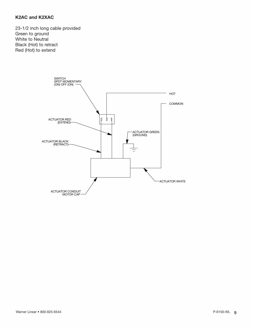
K2AC and K2XAC
23-1/2 inch long cable providedGreen to groundWhite to NeutralBlack (Hot) to retractRed (Hot) to extend
9Warner Linear • 800-825-6544 P-6150-WL
HOT
COMMON
ACTUATOR WHITE
ACTUATOR GREEN(GROUND)
ACTUATOR BLACK(RETRACT)
ACTUATOR RED(EXTEND)
SWITCHSPDT MOMENTARY(ON) OFF (ON)
ACTUATOR CONDUITMOTOR CAP
D
C
B
A
B
C
D
678
8 7 6
BEAR LINEAR
SCALE 1:1
SIZE PART NUMBER
BREV.
UNLESS NOTED:DIMENSIONS ARE IN INCHESTOLERANCES: .XXX = +/-.005" & MAX FINISH 60 Ra .XX = +/-.010" & MAX FINISH 125 Ra .X = +/-.060" & MAX FINISH 250 Ra ANGULAR: +/- 3 GEOMETRIC TOLERANCING PER ANSI Y14.9BREAK ALL CORNERS .010" NO SHARP BURRS
NAME DATE
DRAWN
CHECKED
ENG APPR.
MFG APPR.
Q.A.
SHEET 1 OF 1
COMMENTS:
PROPRIETARY AND CONFIDENTIAL
THE INFORMATION CONTAINED IN THISDRAWING IS THE SOLE PROPERTY OF
BEAR LINEAR. ANY REPRODUCTION IN PART OR AS A WHOLE
WITHOUT THE WRITTEN PERMISSION OFBEAR LINEAR IS PROHIBITED.
MATERIAL
TITLE
AC MOTOR WIRING DIAGRAM
N/A
AC MOTOR WIRE DIAGRAM
JRZJRZ 4/29/2010
NW
4/29/2010
CREATEDThursday, April 29, 2010 8:19:49 AM
5 4 3 2 1
12345
A
Troubleshooting
10 Warner Linear • 800-825-6544 P-6150-WL
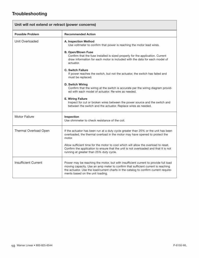
Unit will not extend or retract (power concerns)
Possible Problem Recommended Action
Unit Overloaded A. Inspection Method
Use voltmeter to confirm that power is reaching the motor lead wires.
B. Open/Blown Fuse
Confirm that the fuse installed is sized properly for the application. Currentdraw information for each motor is included with the data for each model ofactuator.
C. Switch Failure
If power reaches the switch, but not the actuator, the switch has failed andmust be replaced.
D. Switch Wiring
Confirm that the wiring at the switch is accurate per the wiring diagram provid-ed with each model of actuator. Re-wire as needed.
E. Wiring Failure
Inspect for cut or broken wires between the power source and the switch andbetween the switch and the actuator. Replace wires as needed.
Motor Failure Inspection
Use ohmmeter to check resistance of the coil.
Thermal Overload Open If the actuator has been run at a duty cycle greater than 25% or the unit has beenoverloaded, the thermal overload in the motor may have opened to protect themotor.
Allow sufficient time for the motor to cool which will allow the overload to reset.Confirm the application to ensure that the unit is not overloaded and that it is notrunning at greater than 25% duty cycle.
Insufficient Current Power may be reaching the motor, but with insufficient current to provide full loadmoving capacity. Use an amp meter to confirm that sufficient current is reachingthe actuator. Use the load/current charts in the catalog to confirm current require-ments based on the unit loading.
Troubleshooting
11Warner Linear • 800-825-6544 P-6150-WL
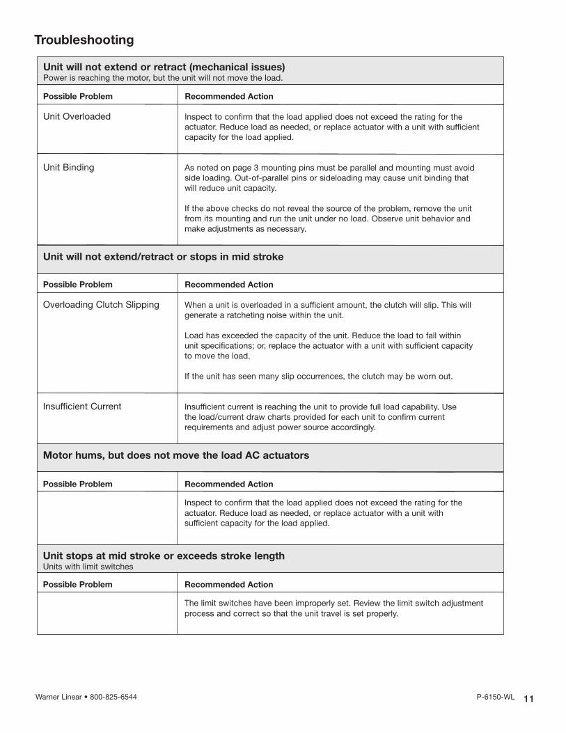
Unit will not extend or retract (mechanical issues)Power is reaching the motor, but the unit will not move the load.
Possible Problem Recommended Action
Unit Overloaded Inspect to confirm that the load applied does not exceed the rating for the actuator. Reduce load as needed, or replace actuator with a unit with sufficientcapacity for the load applied.
Unit Binding As noted on page 3 mounting pins must be parallel and mounting must avoidside loading. Out-of-parallel pins or sideloading may cause unit binding that will reduce unit capacity.
If the above checks do not reveal the source of the problem, remove the unit from its mounting and run the unit under no load. Observe unit behavior andmake adjustments as necessary.
Unit will not extend/retract or stops in mid stroke
Motor hums, but does not move the load AC actuators
Unit stops at mid stroke or exceeds stroke lengthUnits with limit switches
Possible Problem Recommended Action
Overloading Clutch Slipping When a unit is overloaded in a sufficient amount, the clutch will slip. This will generate a ratcheting noise within the unit.
Load has exceeded the capacity of the unit. Reduce the load to fall within unit specifications; or, replace the actuator with a unit with sufficient capacity to move the load.
If the unit has seen many slip occurrences, the clutch may be worn out.
Insufficient Current Insufficient current is reaching the unit to provide full load capability. Use the load/current draw charts provided for each unit to confirm current requirements and adjust power source accordingly.
Possible Problem Recommended Action
Inspect to confirm that the load applied does not exceed the rating for the actuator. Reduce load as needed, or replace actuator with a unit with sufficient capacity for the load applied.
Possible Problem Recommended Action
The limit switches have been improperly set. Review the limit switch adjustmentprocess and correct so that the unit travel is set properly.

Warranty
Warner Linear warrants that it will repair or replace (whichever it deems advisable) any product manufactured and sold by it which proves to be defective in material or workmanshipwithin a period of one (1) year from the date of original purchase for consumer, commercial orindustrial use.
This warranty extends only to the original purchaser and is not transferable or assignable withoutWarner Linear’s prior consent.
Warranty service can be obtained in the U.S.A. by returning any defective product, transportationcharges prepaid, to the appropriate Warner Electric LLC factory. Additional warranty informationmay be obtained by writing the Customer Satisfaction Department, Warner Linear, 5693 RevlonDrive, Belvidere, IL 61008, or by calling 815-547-1106.
A purchase receipt or other proof of original purchase will be required before warranty service is rendered. If found defective under the terms of this warranty, repair or replacement will be made,without charge, together with a refund for transportation costs. If found not to be defective, youwill be notified and, with your consent, the item will be repaired or replaced and returned to youat your expense.
This warranty covers normal use and does not cover damage or defect which results from alteration, accident, neglect, or improper installation, operation, or maintenance.
Some states do not allow limitation on how long an implied warranty lasts, so the above limitationmay not apply to you.
Warner Linear’s obligation under this warranty is limited to the repair or replacement of the defective product and in no event shall Warner Linear be liable for consequential, indirect, or incidental damages of any kind incurred by reason of the manufacture, sale or use of anydefective product. Warner Linear neither assumes nor authorizes any other person to give anyother warranty or to assume any other obligation or liability on its behalf.
WITH RESPECT TO CONSUMER USE OF THE PRODUCT, ANY IMPLIED WARRANTIES WHICHTHE CONSUMER MAY HAVE ARE LIMITED IN DURATION TO ONE YEAR FROM THE DATE OFORIGINAL CONSUMER PURCHASE. WITH RESPECT TO COMMERCIAL AND INDUSTRIAL USES OF THE PRODUCT, THE FOREGOING WARRANTY IS IN LIEU OF AND EXCLUDES ALLOTHER WARRANTIES, WHETHER EXPRESSED OR IMPLIED BY OPERATION OF LAW OR OTHERWISE, INCLUDING, BUT NOT LIMITED TO, ANY IMPLIED WARRANTIES OF MERCHANTABILITY OR FITNESS.
Some states do not allow the exclusion or limitation of incidental or consequential damages, sothe above limitation or exclusion may not apply to you. This warranty gives you specific legalrights and you may also have other rights which vary from state to state.
Changes in Dimensions and SpecificationsAll dimensions and specifications shown in Warner Linear catalogs are subject to change withoutnotice. Weights do not include weight of boxing for shipment. Certified prints will be furnishedwithout charge on request to Warner Linear.
Warner Linear6593 Revlon Drive • Belvidere, IL 61008815-547-1106 • Fax: 815-547-7206Application Assistance: 800-825-9050www.warnerlinear.com
P-6150 8/12 Printed in USA