88-ec - 8800 expander card kit assembly guide kit manual 016.pdf · 88-ec - 8800 expander card kit...
TRANSCRIPT
88-EC - 8800 Expander CardKit Assembly Guide
This is the easiest of the sub kits which make up the basic Altair 8800.
The MITS assembly instructions for this board start on page 64 of the “ALTAIR 8800 ASSEMBLYMANUAL”.
There are a total of 400 solder joints to make on this board. Make sure that you do not bridge any pinstogether! Read through the “MITS Kit Assembly Hints” booklet for soldering tips.
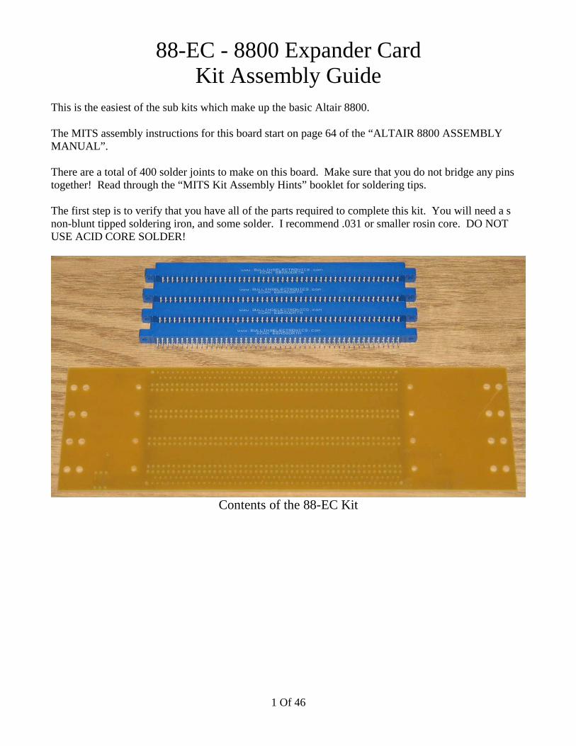
The first step is to verify that you have all of the parts required to complete this kit. You will need a snon-blunt tipped soldering iron, and some solder. I recommend .031 or smaller rosin core. DO NOTUSE ACID CORE SOLDER!
Contents of the 88-EC Kit
1 Of 46

The connectors fit fairly snug in the holes. The easiest way to insert it is by starting on one end androcking it in. Insert all 4 connectors, and make all 100 solder joints on each connector. Make sure theconnectors are fully inserted into the board before soldering!
A partial row of pins has been soldered.
Here is the completed 88-EC board! The wiring for this board will be covered in the enclosure section.
2 Of 46
88-MCS - 8800 1K Static Memory BoardKit Assembly Guide
This is what I consider to be the second easiest kit to assemble in the Altair 8800 Computer kit. Thereare not any different but similar capacitor/resistors. Parts have clear values and designations.
The MITS assembly instructions for this board start on page 40 of the “ALTAIR 8800 ASSEMBLYMANUAL”. I recommend that you read through BOTH the instructions in that manual and this. Myinstructions my have a different order for the steps. One reason is that I include sockets for all ICs andMITS did not. It is your choice which one you will follow.
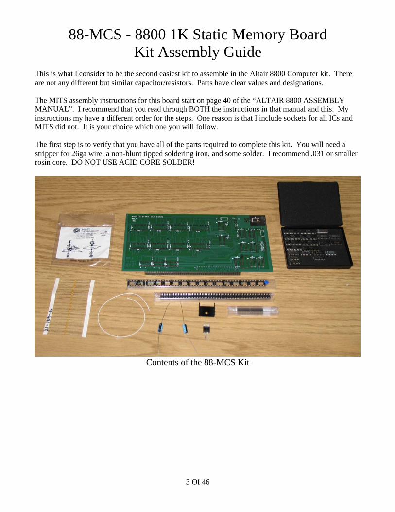
The first step is to verify that you have all of the parts required to complete this kit. You will need astripper for 26ga wire, a non-blunt tipped soldering iron, and some solder. I recommend .031 or smallerrosin core. DO NOT USE ACID CORE SOLDER!
Contents of the 88-MCS Kit
3 Of 46

There are 21 104 (.1uF) capacitors to install on the card. These axial capacitors are much smaller thanthe radial capacitors that MITS included in their kits. The larger radial disc capacitors can be brittle.Because of their height they can be folded and break. The bad thing about these axial capacitors is that itcan be hard to read the value. If you can't read them without glasses, then use a magnifying glass.
SC1 through SC20 and C2 are all 104 (.1uF) axial capacitors. Install the capacitors with the number onthe capacitor body facing upward. On the other kits there are more than one capacitor value in the kit. Itwould be a good idea to get accustomed to making sure the value is facing up so that if the card requirestroubleshooting you can verify them for correct installation. Otherwise they will all look the same. Page42 of the “ALTAIR 8800 ASSEMBLY MANUAL” has MITS's instructions for capacitor installation,page 43 of the same manual has a picture of the silkscreen.
4 Of 46
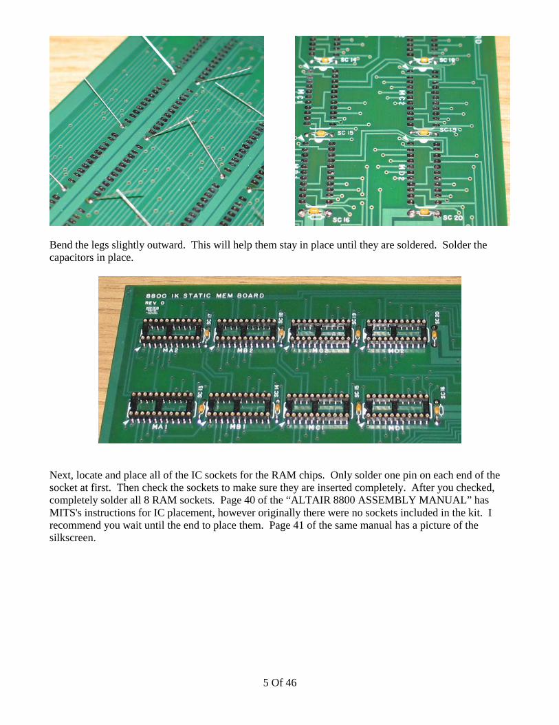
Bend the legs slightly outward. This will help them stay in place until they are soldered. Solder thecapacitors in place.
Next, locate and place all of the IC sockets for the RAM chips. Only solder one pin on each end of thesocket at first. Then check the sockets to make sure they are inserted completely. After you checked,completely solder all 8 RAM sockets. Page 40 of the “ALTAIR 8800 ASSEMBLY MANUAL” hasMITS's instructions for IC placement, however originally there were no sockets included in the kit. Irecommend you wait until the end to place them. Page 41 of the same manual has a picture of thesilkscreen.
5 Of 46
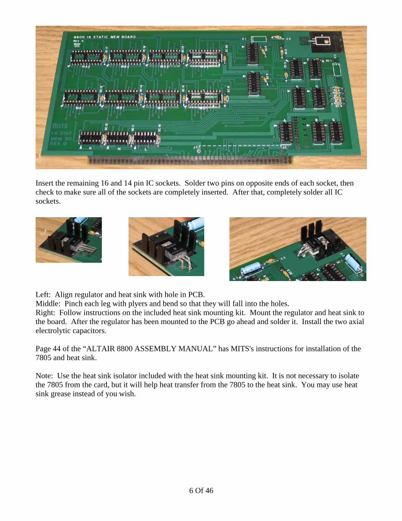
Insert the remaining 16 and 14 pin IC sockets. Solder two pins on opposite ends of each socket, thencheck to make sure all of the sockets are completely inserted. After that, completely solder all ICsockets.
Left: Align regulator and heat sink with hole in PCB.Middle: Pinch each leg with plyers and bend so that they will fall into the holes.Right: Follow instructions on the included heat sink mounting kit. Mount the regulator and heat sink tothe board. After the regulator has been mounted to the PCB go ahead and solder it. Install the two axialelectrolytic capacitors.
Page 44 of the “ALTAIR 8800 ASSEMBLY MANUAL” has MITS's instructions for installation of the7805 and heat sink.
Note: Use the heat sink isolator included with the heat sink mounting kit. It is not necessary to isolatethe 7805 from the card, but it will help heat transfer from the 7805 to the heat sink. You may use heatsink grease instead of you wish.
6 Of 46

Top Left: You can either use small loops of white wire for address selection or the legs trimmed off ofyour capacitors. It is easier to change the cards address with the capacitor legs than with the white wire.If you bend one end of the leg to fall in the series of the holes on the right and trim the other end straight,then changing the address of the card only involves heating up the jumper and pivoting it to the otherpad. For more information on address selection for the board, view page 78 (unnumbered, but the pageafter number 77) in the “ALTAIR 8800 ASSEMBLY MANUAL”.
Top Right: This is the default address setting for the card. This will place the card in memory spacefrom 0x0000 to 0x03FF (000000 to 001777 octal). Unless you know why you would want a differentconfiguration (more than one card for example), then wire your card like the picture above.
Bottom Middle: Install jumper J1.
Page 45 of the “ALTAIR 8800 ASSEMBLY MANUAL” has MITS's instructions for the hardwirejumper connections. Page 46 of the same manual has a picture of the silkscreen.
7 Of 46

You are now ready to install the ICs. Please see page 41 of the “ALTAIR 8800 ASSEMBLYMANUAL” for a picture of the silkscreen and instructions for locating the ICs in their sockets.
CONGRATULATIONS! You are done with the board! If you are building an entire Altair 8800Computer kit, then the project has just begun...
8 Of 46

88-CPU - 8800 8080 CPU BoardKit Assembly Guide
This kit is a little more complex than the 88-MCS 1k memory board. The 88-MCS only had one valueof capacitor and the CPU board has several. The CPU board also has several different resistor values.
The MITS assembly instructions for this board start on page 26 of the “ALTAIR 8800 ASSEMBLYMANUAL”. I recommend that you read through BOTH the instructions in that manual and this. Myinstructions my have a different order for the steps. One reason is that I include sockets for all ICs andMITS did not. It is your choice which one you will follow.
The first step is to verify that you have all of the parts required to complete this kit. You will need astripper for 26ga wire, a non-blunt tipped soldering iron, and some solder. I recommend .031 or smallerrosin core. DO NOT USE ACID CORE SOLDER!
Contents of the 88-CPU Kit
9 Of 46
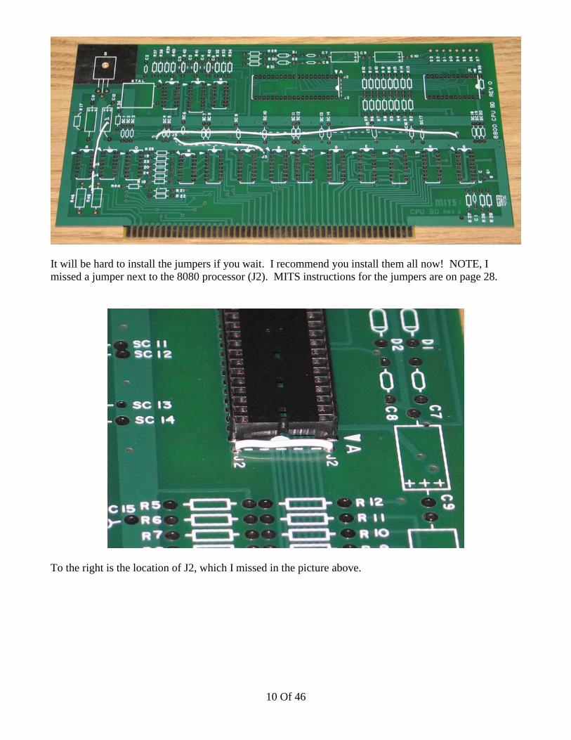
It will be hard to install the jumpers if you wait. I recommend you install them all now! NOTE, Imissed a jumper next to the 8080 processor (J2). MITS instructions for the jumpers are on page 28.
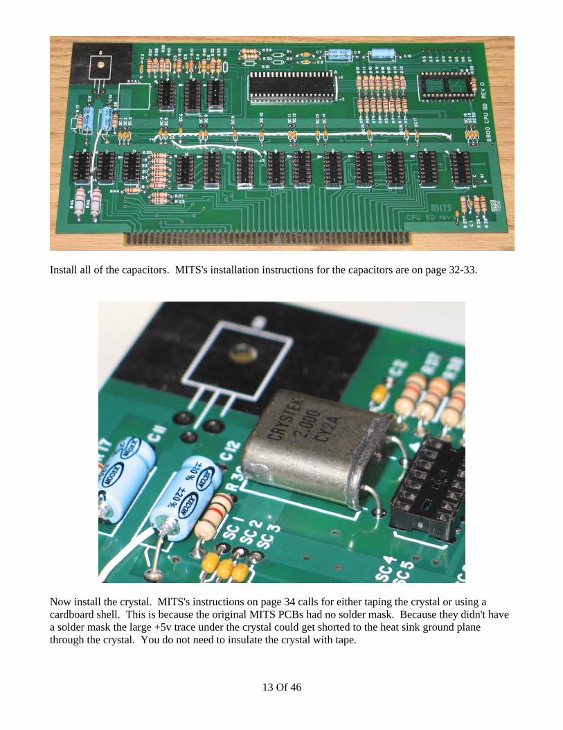
To the right is the location of J2, which I missed in the picture above.
10 Of 46

You can install J4 as indicated on the PCB legend, or you can install it in the hole below. I chose thehole below because its easier to handle a slightly longer jumper (stripping, etc)
Next install all of the sockets. The 24 pin socket is not shown installed but it should be soldered at thistime. MITS does not include instructions for socket installation except for the 40 and 24pin sockets.
11 Of 46

Follow the instructions on page 30-31 for installing the resistors. NOTE: I've found that at least R42must be substituted for a 4.3k resistor for the clock circuit to function properly. Included is the resistorMITS calls for in the manual, as well as a 4.3k resistor.
I recommend that you take your time installing all of the resistors and capacitors so that your board looksas good as possible. For example, insert all of the resistors so that the gold band is facing the samedirection. Orient all of the capacitors so that the value is facing upwards. NOTE: Make sure to installthe electrolytic capacitors as indicated! They are polarized and should only be inserted one way!
12 Of 46
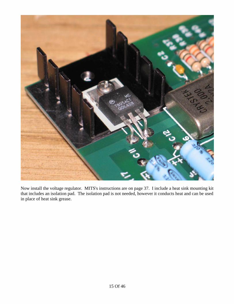
Install all of the capacitors. MITS's installation instructions for the capacitors are on page 32-33.
Now install the crystal. MITS's instructions on page 34 calls for either taping the crystal or using acardboard shell. This is because the original MITS PCBs had no solder mask. Because they didn't havea solder mask the large +5v trace under the crystal could get shorted to the heat sink ground planethrough the crystal. You do not need to insulate the crystal with tape.
13 Of 46

Next install the zener diodes. These along with the two 2-watt resistors in the lower left corner make uptwo voltage regulators for the CPU. MITS's instructions for installing the zener diodes are on page 34-35.
D1 is a 12v 1N4742D2 is a 5v 1N4733
Now install the transistor. This transistor is responsible for generating a “Power On Clear” to reset I/Odevices when power is applied. MITS's instructions for installing the transistor are on page 36.
14 Of 46
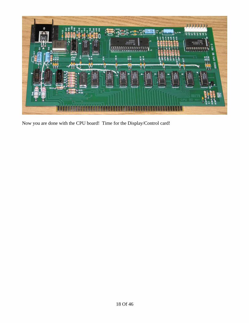
Now install the voltage regulator. MITS's instructions are on page 37. I include a heat sink mounting kitthat includes an isolation pad. The isolation pad is not needed, however it conducts heat and can be usedin place of heat sink grease.
15 Of 46

One of the modifications required is adding a .001uf capacitor to the CPU board. The capacitor islocated next to R27. Look on page MITS's page 38A for more details.
Lightly scratch the solder mask off of the pad to enable soldering. Do not use excessive solder on thisconnection. The solder should be limited to the top half circle shape at the top. If the card edge bladehas excessive solder it could damage the connector on the motherboard.
16 Of 46

The last item to solder on the CPU board is the 8-pin wafer connector. MITS's instructions for this areon page 39.
Next install all of the ICs. MITS's instructions on page 27 tells you exactly where each IC goes.
17 Of 46
Now you are done with the CPU board! Time for the Display/Control card!
18 Of 46
88-DC - 8800 Display/Control BoardKit Assembly Guide
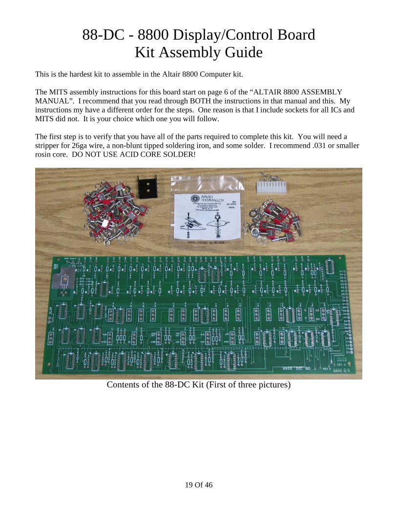
This is the hardest kit to assemble in the Altair 8800 Computer kit.
The MITS assembly instructions for this board start on page 6 of the “ALTAIR 8800 ASSEMBLYMANUAL”. I recommend that you read through BOTH the instructions in that manual and this. Myinstructions my have a different order for the steps. One reason is that I include sockets for all ICs andMITS did not. It is your choice which one you will follow.
The first step is to verify that you have all of the parts required to complete this kit. You will need astripper for 26ga wire, a non-blunt tipped soldering iron, and some solder. I recommend .031 or smallerrosin core. DO NOT USE ACID CORE SOLDER!
Contents of the 88-DC Kit (First of three pictures)
19 Of 46
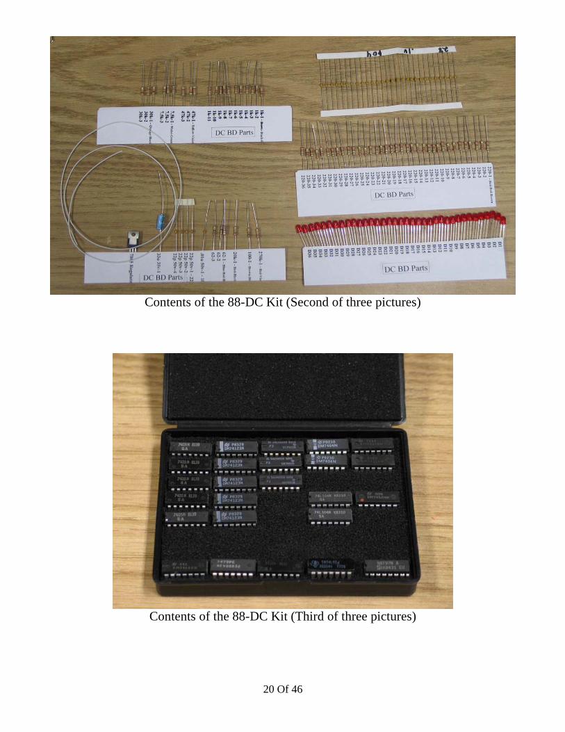
Contents of the 88-DC Kit (Second of three pictures)
Contents of the 88-DC Kit (Third of three pictures)
20 Of 46

First I recommend you install J2. After the IC sockets are installed it will be a little harder.
Now install all of the IC sockets. MITS did not include instructions for socket installation because theydid not include sockets.
21 Of 46

Install all of the resistors. MITS's instructions for installing the resistors is on pages 8 and 9.
Install all of the capacitors. MITS's instructions for installing the capacitors is on pages 10 and 11.
22 Of 46
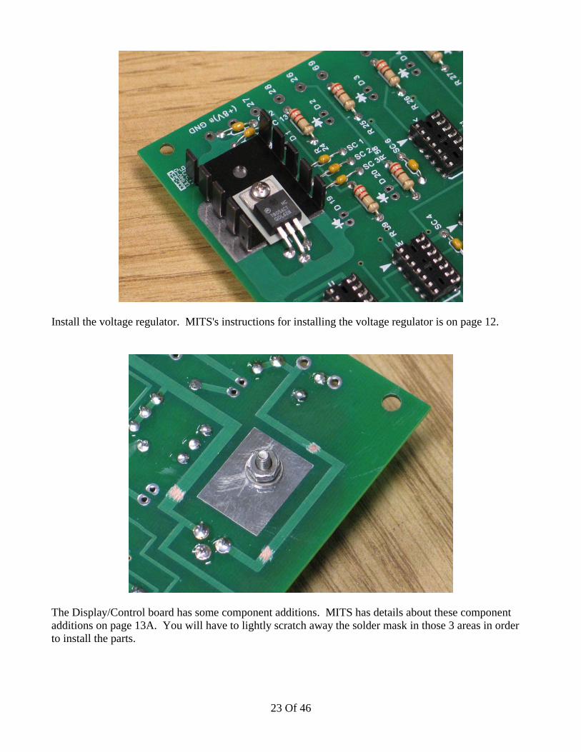
Install the voltage regulator. MITS's instructions for installing the voltage regulator is on page 12.
The Display/Control board has some component additions. MITS has details about these componentadditions on page 13A. You will have to lightly scratch away the solder mask in those 3 areas in orderto install the parts.
23 Of 46

The extra components have been added to the Display/Control board.
At this point it makes sense to start working with the case. The construction of the Display/Controlboard will continue in the next section.
24 Of 46
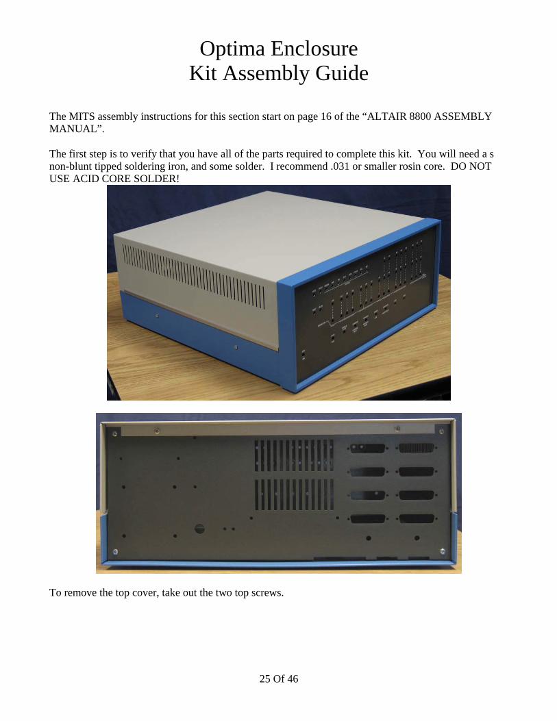
Optima EnclosureKit Assembly Guide
The MITS assembly instructions for this section start on page 16 of the “ALTAIR 8800 ASSEMBLYMANUAL”.
The first step is to verify that you have all of the parts required to complete this kit. You will need a snon-blunt tipped soldering iron, and some solder. I recommend .031 or smaller rosin core. DO NOTUSE ACID CORE SOLDER!
To remove the top cover, take out the two top screws.
25 Of 46
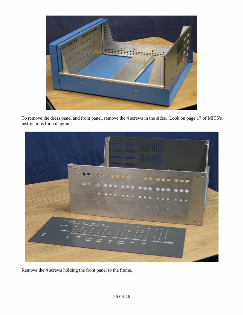
To remove the dress panel and front panel, remove the 4 screws in the sides. Look on page 17 of MITS'sinstructions for a diagram.
Remove the 4 screws holding the front panel to the frame.
26 Of 46
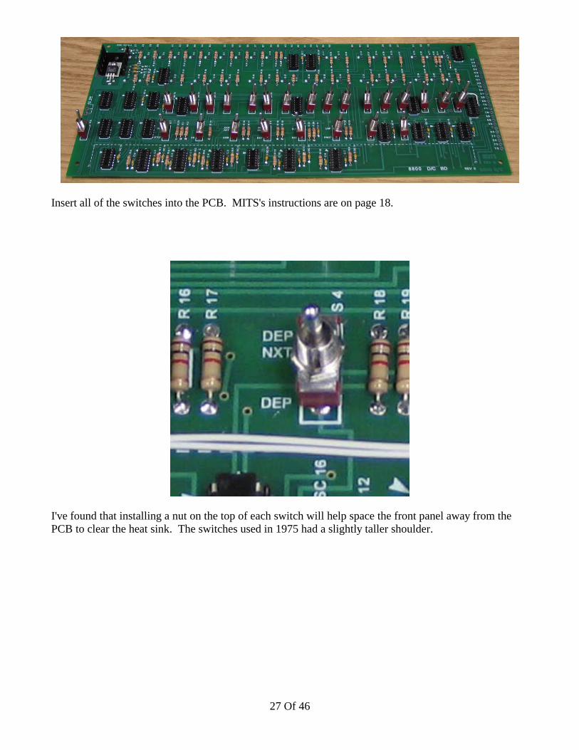
Insert all of the switches into the PCB. MITS's instructions are on page 18.
I've found that installing a nut on the top of each switch will help space the front panel away from thePCB to clear the heat sink. The switches used in 1975 had a slightly taller shoulder.
27 Of 46
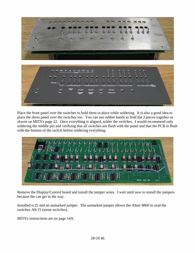
Place the front panel over the switches to hold them in place while soldering. It is also a good idea toplace the dress panel over the switches too. You can use rubber bands to hold the 3 pieces together asshwon on MITS's page 22. Once everything is aligned, solder the switches. I would recommend onlysoldering the middle pin and verifying that all switches are flush with the panel and that the PCB is flushwith the bottom of the switch before soldering everything.
Remove the Display/Control board and install the jumper wires. I wait until now to install the jumpersbecause the can get in the way.
Installed is J2 and an unmarked jumper. The unmarked jumper allows the Altair 8800 to read theswitches A8-15 (sense switches).
MITS's instructions are on page 14A.
28 Of 46
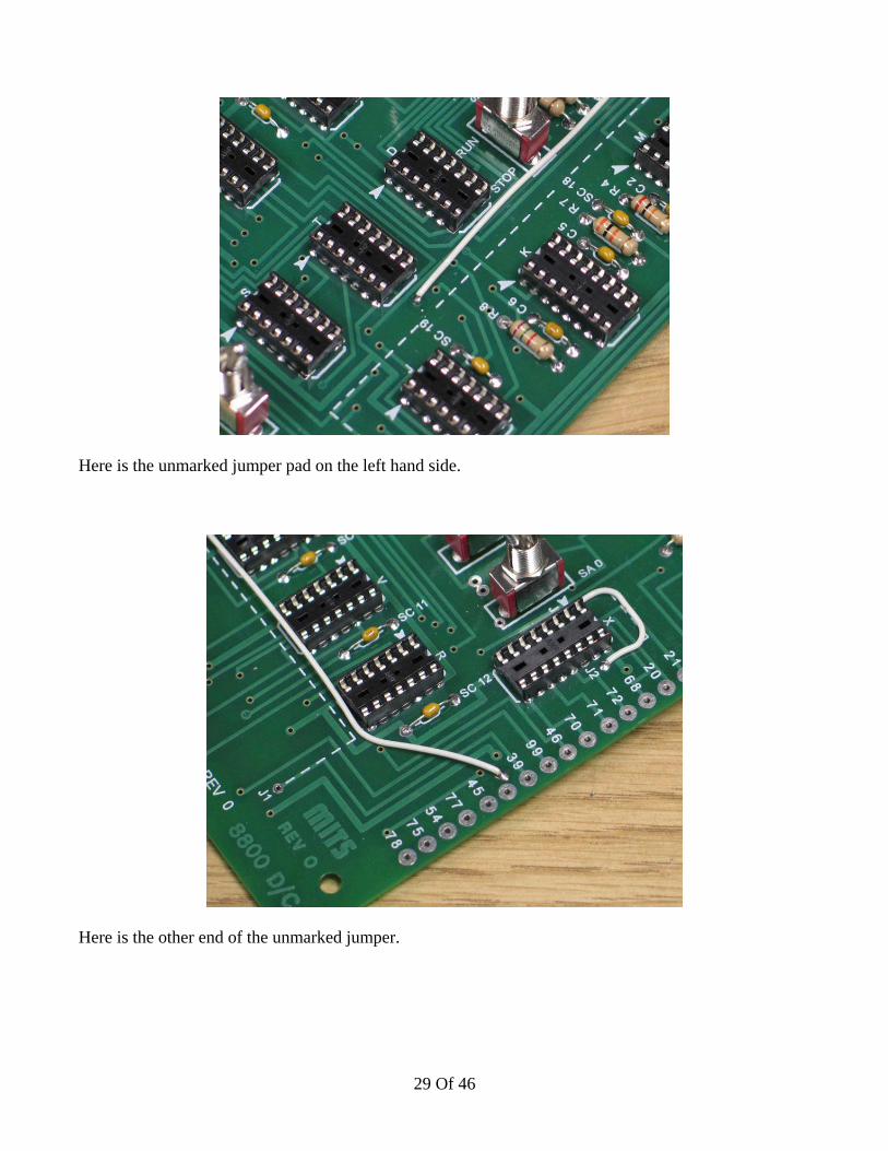
Here is the unmarked jumper pad on the left hand side.
Here is the other end of the unmarked jumper.
29 Of 46
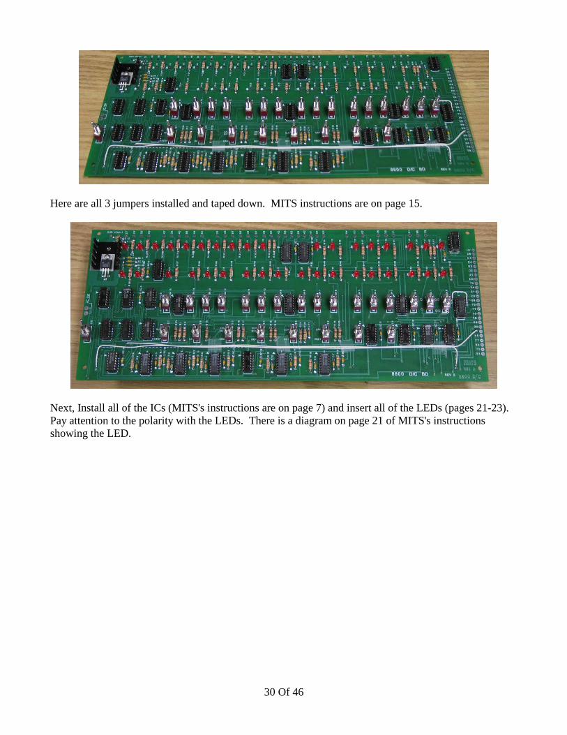
Here are all 3 jumpers installed and taped down. MITS instructions are on page 15.
Next, Install all of the ICs (MITS's instructions are on page 7) and insert all of the LEDs (pages 21-23).Pay attention to the polarity with the LEDs. There is a diagram on page 21 of MITS's instructionsshowing the LED.
30 Of 46

Reinstall the front panel to the the PCB except this time use nuts on top of the front panel. I don't useevery single nut because it isn't necessary. I used about 5 of them.
Place the dress panel over the front panel and switches. Push the LEDs from the back to the depth thatyou want. I like my LEDs out as far as they go. Others like the LEDs flush with the dress panel becausethey say it improves the contrast. It doesn't change the way the Altair operates...
31 Of 46
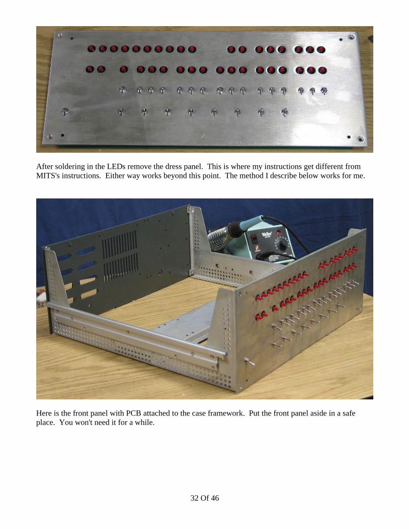
After soldering in the LEDs remove the dress panel. This is where my instructions get different fromMITS's instructions. Either way works beyond this point. The method I describe below works for me.
Here is the front panel with PCB attached to the case framework. Put the front panel aside in a safeplace. You won't need it for a while.
32 Of 46

Here is the crossbar. It comes drilled like the original part from MITS. In order to mount the switchingpower supplies you will need to drill new holes. A drill pattern is included to make this easy. It giveshole placement and pattern alignment.
Here is the crossbar with the additional holes drilled.
33 Of 46
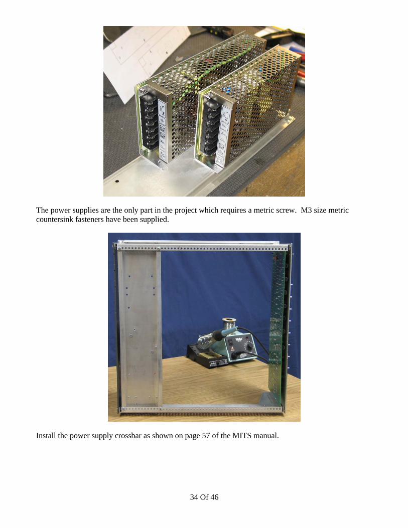
The power supplies are the only part in the project which requires a metric screw. M3 size metriccountersink fasteners have been supplied.
Install the power supply crossbar as shown on page 57 of the MITS manual.
34 Of 46

Fastener parts required for attaching the aluminum card rail motherboard supports.
Install according to page 57 of the MITS manual.
Fastener parts required for attaching the motherboard to the aluminum card rails.
35 Of 46
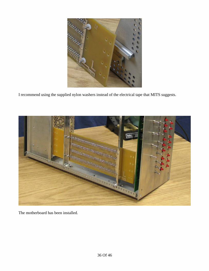
I recommend using the supplied nylon washers instead of the electrical tape that MITS suggests.
The motherboard has been installed.
36 Of 46
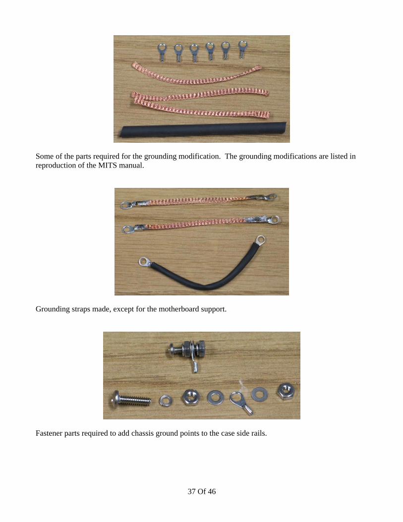
Some of the parts required for the grounding modification. The grounding modifications are listed inreproduction of the MITS manual.
Grounding straps made, except for the motherboard support.
Fastener parts required to add chassis ground points to the case side rails.
37 Of 46
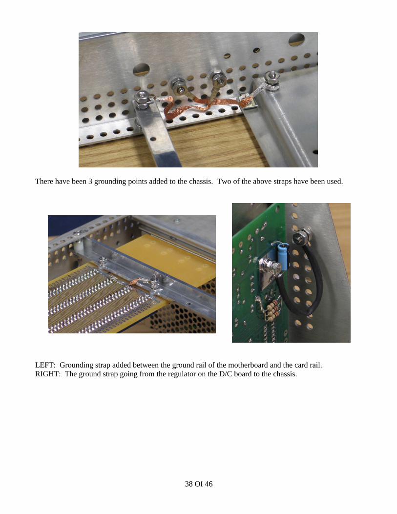
There have been 3 grounding points added to the chassis. Two of the above straps have been used.
LEFT: Grounding strap added between the ground rail of the motherboard and the card rail.RIGHT: The ground strap going from the regulator on the D/C board to the chassis.
38 Of 46
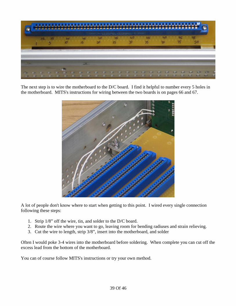
The next step is to wire the motherboard to the D/C board. I find it helpful to number every 5 holes inthe motherboard. MITS's instructions for wiring between the two boards is on pages 66 and 67.
A lot of people don't know where to start when getting to this point. I wired every single connectionfollowing these steps:
1. Strip 1/8” off the wire, tin, and solder to the D/C board.2. Route the wire where you want to go, leaving room for bending radiuses and strain relieving.3. Cut the wire to length, strip 3/8”, insert into the motherboard, and solder
Often I would poke 3-4 wires into the motherboard before soldering. When complete you can cut off theexcess lead from the bottom of the motherboard.
You can of course follow MITS's instructions or try your own method.
39 Of 46

On the left we have a D/C board wired and waiting for the KK connector. On the right is the KKconnector and crimp pins. Follow MITS's instructions on page 24 for wiring instructions.
40 Of 46
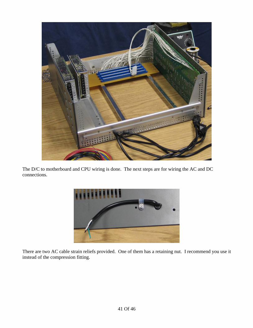
The D/C to motherboard and CPU wiring is done. The next steps are for wiring the AC and DCconnections.
There are two AC cable strain reliefs provided. One of them has a retaining nut. I recommend you use itinstead of the compression fitting.
41 Of 46
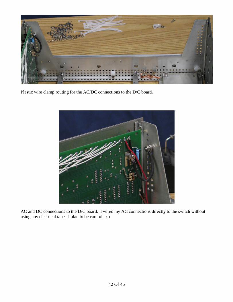
Plastic wire clamp routing for the AC/DC connections to the D/C board.
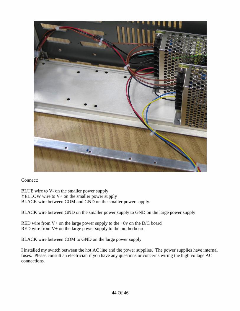
AC and DC connections to the D/C board. I wired my AC connections directly to the switch withoutusing any electrical tape. I plan to be careful. : )
42 Of 46

In this case, I've used the following colors for the following voltages:
RED: +8vDCBLUE: -16vDCYELLOW: +16vDC
BLACK: Ground
43 Of 46
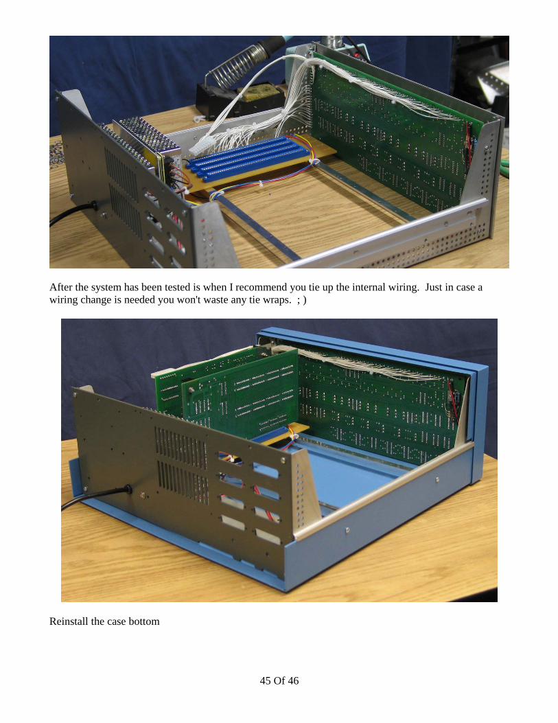
Connect:
BLUE wire to V- on the smaller power supplyYELLOW wire to V+ on the smaller power supplyBLACK wire between COM and GND on the smaller power supply.
BLACK wire between GND on the smaller power supply to GND on the large power supply
RED wire from V+ on the large power supply to the +8v on the D/C boardRED wire from V+ on the large power supply to the motherboard
BLACK wire between COM to GND on the large power supply
I installed my switch between the hot AC line and the power supplies. The power supplies have internalfuses. Please consult an electrician if you have any questions or concerns wiring the high voltage ACconnections.
44 Of 46
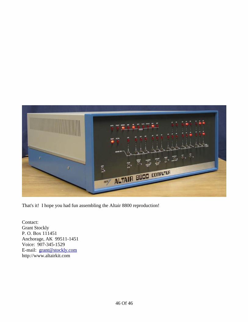
After the system has been tested is when I recommend you tie up the internal wiring. Just in case awiring change is needed you won't waste any tie wraps. ; )
Reinstall the case bottom
45 Of 46
That's it! I hope you had fun assembling the Altair 8800 reproduction!
Contact:Grant StocklyP. O. Box 111451Anchorage, AK 99511-1451Voice: 907-345-1529E-mail: [email protected]://www.altairkit.com
46 Of 46