88192 a/d d/a converter - symetrix · the lucid 88192 a/d d/a converter features eight channels of...
TRANSCRIPT
88192 A/D D/A ConverterUser’s Guide

6408 216th Street SW | Mountlake Terrace, WA 98043 USA
T +1.425.778.7728 F +1.425.778.7727 | www.SymetrixAudio.com 2
User’s GuideSafety
3
88192 A/D D/A Converter Safety
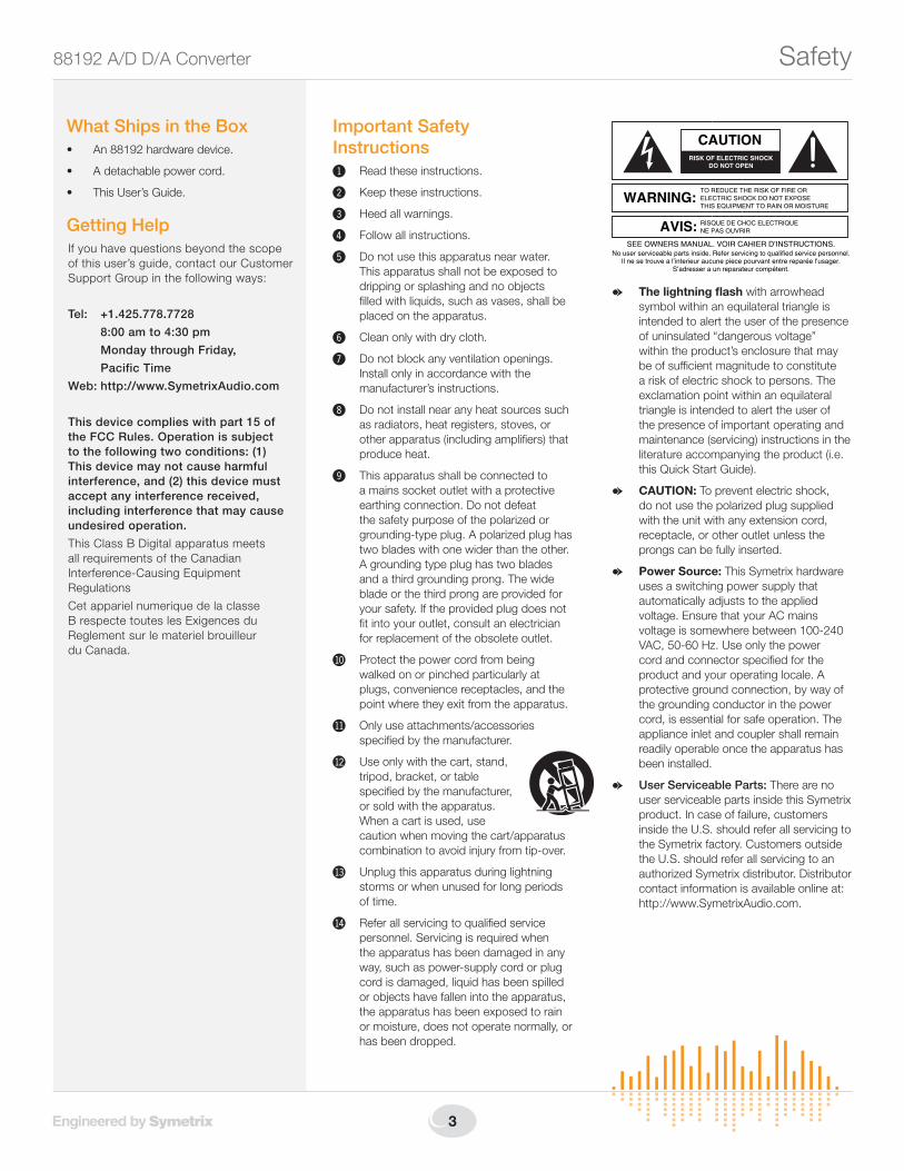
G The lightning flash with arrowhead symbol within an equilateral triangle is intended to alert the user of the presence of uninsulated “dangerous voltage” within the product’s enclosure that may be of sufficient magnitude to constitute a risk of electric shock to persons. The exclamation point within an equilateral triangle is intended to alert the user of the presence of important operating and maintenance (servicing) instructions in the literature accompanying the product (i.e. this Quick Start Guide).
G CAUTION: To prevent electric shock, do not use the polarized plug supplied with the unit with any extension cord, receptacle, or other outlet unless the prongs can be fully inserted.
G Power Source: This Symetrix hardware uses a switching power supply that automatically adjusts to the applied voltage. Ensure that your AC mains voltage is somewhere between 100-240 VAC, 50-60 Hz. Use only the power cord and connector specified for the product and your operating locale. A protective ground connection, by way of the grounding conductor in the power cord, is essential for safe operation. The appliance inlet and coupler shall remain readily operable once the apparatus has been installed.
G User Serviceable Parts: There are no user serviceable parts inside this Symetrix product. In case of failure, customers inside the U.S. should refer all servicing to the Symetrix factory. Customers outside the U.S. should refer all servicing to an authorized Symetrix distributor. Distributor contact information is available online at: http://www.SymetrixAudio.com.
AVIS: NE PAS OUVRIR
Il ne se trouve a l’interieur aucune piece pourvant entre reparée l’usager.
SEE OWNERS MANUAL. VOIR CAHIER D’INSTRUCTIONS.
S’adresser a un reparateur compétent.
RISQUE DE CHOC ELECTRIQUE
No user serviceable parts inside. Refer servicing to qualified service personnel.
CAUTION
WARNING:TO REDUCE THE RISK OF FIRE ORELECTRIC SHOCK DO NOT EXPOSETHIS EQUIPMENT TO RAIN OR MOISTURE
DO NOT OPENRISK OF ELECTRIC SHOCK
Important Safety Instructions! Read these instructions.
@ Keep these instructions.
# Heed all warnings.
$ Follow all instructions.
% Do not use this apparatus near water. This apparatus shall not be exposed to dripping or splashing and no objects filled with liquids, such as vases, shall be placed on the apparatus.
^ Clean only with dry cloth.
& Do not block any ventilation openings. Install only in accordance with the manufacturer’s instructions.
* Do not install near any heat sources such as radiators, heat registers, stoves, or other apparatus (including amplifiers) that produce heat.
( This apparatus shall be connected to a mains socket outlet with a protective earthing connection. Do not defeat the safety purpose of the polarized or grounding-type plug. A polarized plug has two blades with one wider than the other. A grounding type plug has two blades and a third grounding prong. The wide blade or the third prong are provided for your safety. If the provided plug does not fit into your outlet, consult an electrician for replacement of the obsolete outlet.
BL Protect the power cord from being walked on or pinched particularly at plugs, convenience receptacles, and the point where they exit from the apparatus.
BM Only use attachments/accessories specified by the manufacturer.
BN Use only with the cart, stand, tripod, bracket, or table specified by the manufacturer, or sold with the apparatus. When a cart is used, use caution when moving the cart/apparatus combination to avoid injury from tip-over.
BO Unplug this apparatus during lightning storms or when unused for long periods of time.
BP Refer all servicing to qualified service personnel. Servicing is required when the apparatus has been damaged in any way, such as power-supply cord or plug cord is damaged, liquid has been spilled or objects have fallen into the apparatus, the apparatus has been exposed to rain or moisture, does not operate normally, or has been dropped.
What Ships in the Box• An88192hardwaredevice.
• Adetachablepowercord.
• ThisUser’sGuide.
Getting HelpIf you have questions beyond the scope of this user’s guide, contact our Customer Support Group in the following ways:
Tel: +1.425.778.7728
8:00 am to 4:30 pm
Monday through Friday,
Pacific Time
Web: http://www.SymetrixAudio.com
This device complies with part 15 of the FCC Rules. Operation is subject to the following two conditions: (1) This device may not cause harmful interference, and (2) this device must accept any interference received, including interference that may cause undesired operation.
This Class B Digital apparatus meets all requirements of the Canadian Interference-Causing Equipment Regulations
Cet appariel numerique de la classe B respecte toutes les Exigences du Reglement sur le materiel brouilleur du Canada.
6408 216th Street SW | Mountlake Terrace, WA 98043 USA
T +1.425.778.7728 F +1.425.778.7727 | www.SymetrixAudio.com 4
User’s GuideIntroduction
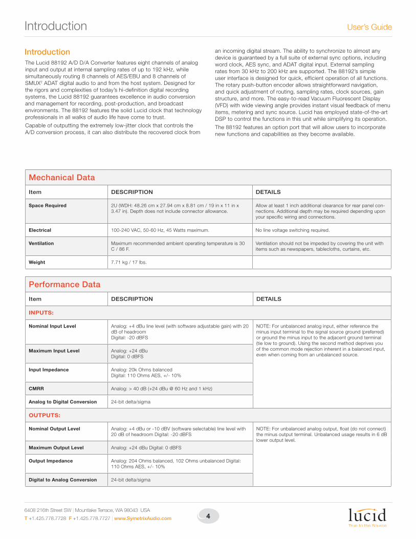
IntroductionThe Lucid 88192 A/D D/A Converter features eight channels of analog input and output at internal sampling rates of up to 192 kHz, while simultaneously routing 8 channels of AES/EBU and 8 channels of SMUX2 ADAT digital audio to and from the host system. Designed for the rigors and complexities of today’s hi-definition digital recording systems, the Lucid 88192 guarantees excellence in audio conversion and management for recording, post-production, and broadcast environments. The 88192 features the solid Lucid clock that technology professionals in all walks of audio life have come to trust.
Capable of outputting the extremely low-jitter clock that controls the A/D conversion process, it can also distribute the recovered clock from
an incoming digital stream. The ability to synchronize to almost any device is guaranteed by a full suite of external sync options, including word clock, AES sync, and ADAT digital input. External sampling rates from 30 kHz to 200 kHz are supported. The 88192’s simple user interface is designed for quick, efficient operation of all functions. The rotary push-button encoder allows straightforward navigation, and quick adjustment of routing, sampling rates, clock sources, gain structure, and more. The easy-to-read Vacuum Fluorescent Display (VFD) with wide viewing angle provides instant visual feedback of menu items, metering and sync source. Lucid has employed state-of-the-art DSP to control the functions in this unit while simplifying its operation.
The 88192 features an option port that will allow users to incorporate new functions and capabilities as they become available.
Performance Data
Item DESCRIPTION DETAILS
INPUTS:
Nominal Input Level Analog: +4 dBu line level (with software adjustable gain) with 20 dB of headroom Digital: -20 dBFS
NOTE: For unbalanced analog input, either refer ence the minus input terminal to the signal source ground (pre ferred) or ground the minus input to the adjacent ground terminal (tie low to ground). Using the second method deprives you of the common mode rejection inher ent in a balanced input, even when coming from an unbalanced source.
Maximum Input Level Analog: +24 dBu Digital: 0 dBFS
Input Impedance Analog: 20k Ohms balanced Digital: 110 Ohms AES, +/- 10%
CMRR Analog: > 40 dB (+24 dBu @ 60 Hz and 1 kHz)
Analog to Digital Conversion 24-bit delta/sigma
OUTPUTS:
Nominal Output Level Analog: +4 dBu or -10 dBV (software selectable) line level with 20 dB of headroom Digital: -20 dBFS
NOTE: For unbalanced analog output, float (do not connect) the minus output terminal. Unbalanced usage results in 6 dB lower output level.
Maximum Output Level Analog: +24 dBu Digital: 0 dBFS
Output Impedance Analog: 204 Ohms balanced, 102 Ohms unbalanced Digital: 110 Ohms AES, +/- 10%
Digital to Analog Conversion 24-bit delta/sigma
Mechanical Data
Item DESCRIPTION DETAILS
Space Required 2U (WDH: 48.26 cm x 27.94 cm x 8.81 cm / 19 in x 11 in x 3.47 in). Depth does not include connector allowance.
Allow at least 1 inch additional clearance for rear panel con-nections. Additional depth may be required depending upon your specific wiring and connections.
Electrical 100-240 VAC, 50-60 Hz, 45 Watts maximum. No line voltage switching required.
Ventilation Maximum recommended ambient operating temperature is 30 C / 86 F.
Ventilation should not be impeded by covering the unit with items such as newspapers, tablecloths, curtains, etc.
Weight 7.71 kg / 17 lbs.
5
88192 A/D D/A Converter Hardware
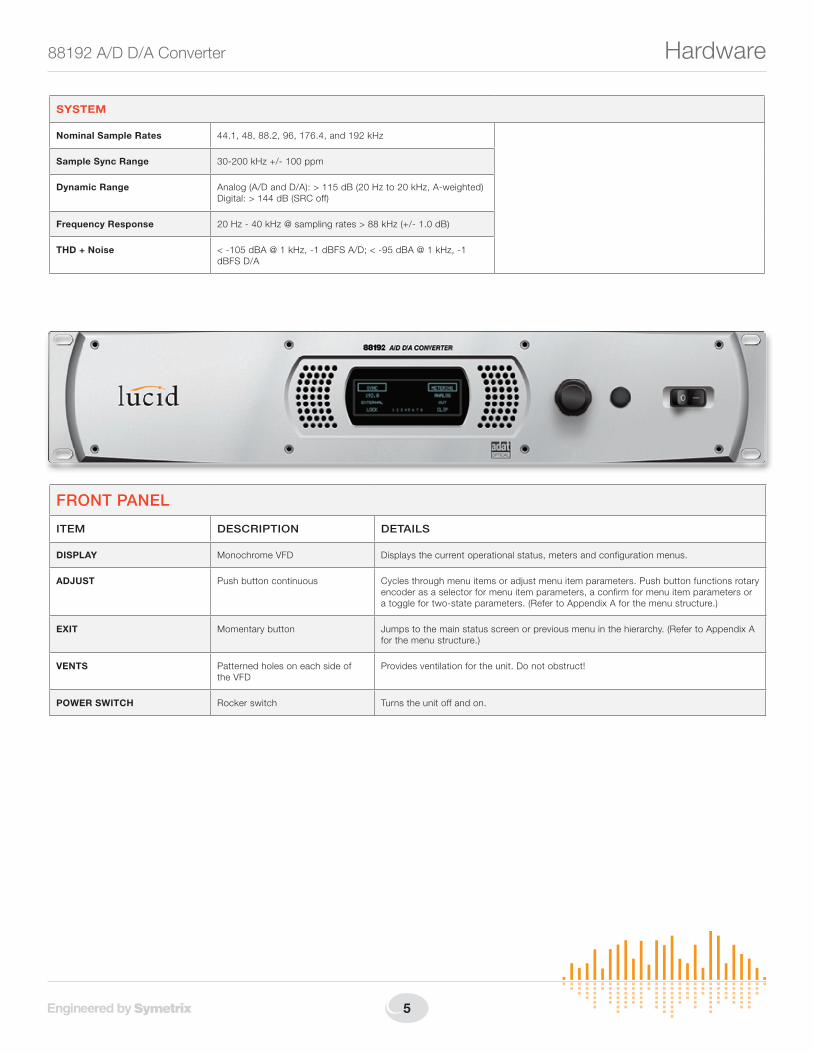
FRONT PANEL
ITEM DESCRIPTION DETAILS
DISPLAY Monochrome VFD Displays the current operational status, meters and configuration menus.
ADJUST Push button continuous Cycles through menu items or adjust menu item parameters. Push button functions rotary encoder as a selector for menu item parameters, a confirm for menu item parameters or a toggle for two-state parameters. (Refer to Appendix A for the menu structure.)
EXIT Momentary button Jumps to the main status screen or previous menu in the hierarchy. (Refer to Appendix A for the menu structure.)
VENTS Patterned holes on each side of the VFD
Provides ventilation for the unit. Do not obstruct!
POWER SWITCH Rocker switch Turns the unit off and on.
SYSTEM
Nominal Sample Rates 44.1, 48, 88.2, 96, 176.4, and 192 kHz
Sample Sync Range 30-200 kHz +/- 100 ppm
Dynamic Range Analog (A/D and D/A): > 115 dB (20 Hz to 20 kHz, A-weighted) Digital: > 144 dB (SRC off)
Frequency Response 20 Hz - 40 kHz @ sampling rates > 88 kHz (+/- 1.0 dB)
THD + Noise < -105 dBA @ 1 kHz, -1 dBFS A/D; < -95 dBA @ 1 kHz, -1 dBFS D/A
6408 216th Street SW | Mountlake Terrace, WA 98043 USA
T +1.425.778.7728 F +1.425.778.7727 | www.SymetrixAudio.com 6
User’s GuideRear Panel
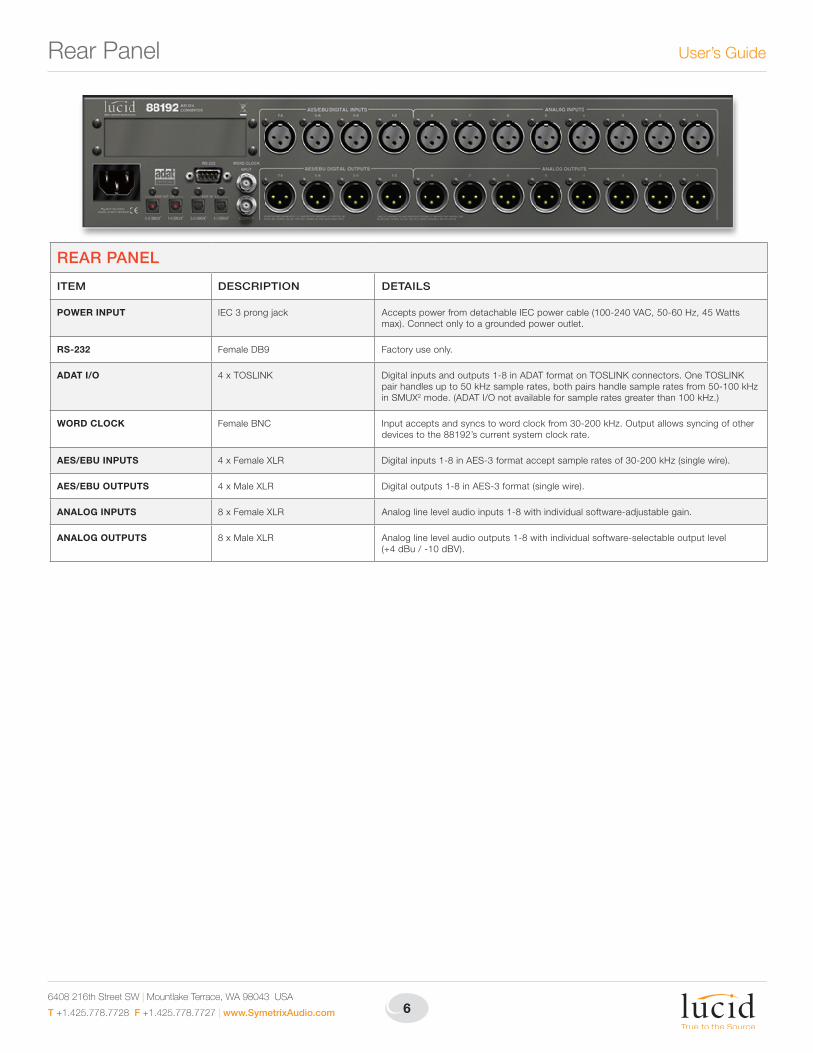
REAR PANEL
ITEM DESCRIPTION DETAILS
POWER INPUT IEC 3 prong jack Accepts power from detachable IEC power cable (100-240 VAC, 50-60 Hz, 45 Watts max). Connect only to a grounded power outlet.
RS-232 Female DB9 Factory use only.
ADAT I/O 4 x TOSLINK Digital inputs and outputs 1-8 in ADAT format on TOSLINK connectors. One TOSLINK pair handles up to 50 kHz sample rates, both pairs handle sample rates from 50-100 kHz in SMUX2 mode. (ADAT I/O not available for sample rates greater than 100 kHz.)
WORD CLOCK Female BNC Input accepts and syncs to word clock from 30-200 kHz. Output allows syncing of other devices to the 88192’s current system clock rate.
AES/EBU INPUTS 4 x Female XLR Digital inputs 1-8 in AES-3 format accept sample rates of 30-200 kHz (single wire).
AES/EBU OUTPUTS 4 x Male XLR Digital outputs 1-8 in AES-3 format (single wire).
ANALOG INPUTS 8 x Female XLR Analog line level audio inputs 1-8 with individual software-adjustable gain.
ANALOG OUTPUTS 8 x Male XLR Analog line level audio outputs 1-8 with individual software-selectable output level (+4 dBu / -10 dBV).
7
88192 A/D D/A Converter Hardware Connections
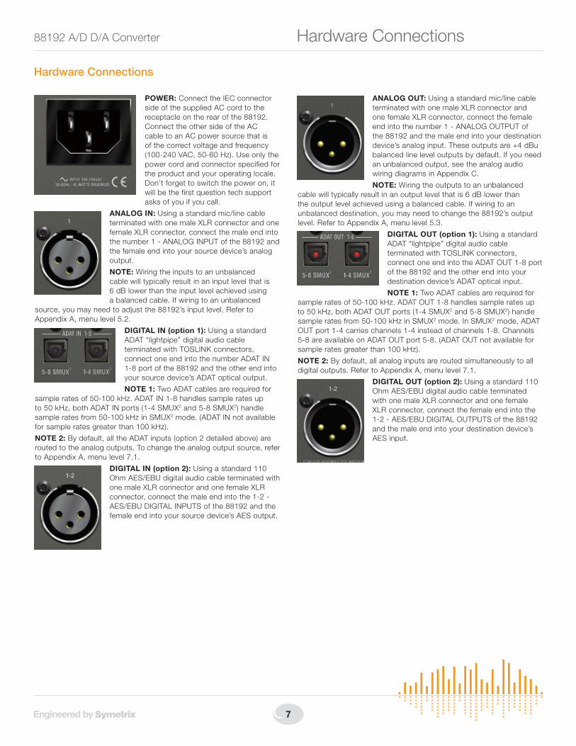
Hardware Connections
POWER: Connect the IEC connector side of the supplied AC cord to the receptacle on the rear of the 88192. Connect the other side of the AC cable to an AC power source that is of the correct voltage and frequency (100-240 VAC, 50-60 Hz). Use only the power cord and connector specified for the product and your operating locale. Don’t forget to switch the power on, it will be the first question tech support asks of you if you call.
ANALOG IN: Using a standard mic/line cable terminated with one male XLR connector and one female XLR connector, connect the male end into the number 1 - ANALOG INPUT of the 88192 and the female end into your source device’s analog output.
NOTE: Wiring the inputs to an unbalanced cable will typically result in an input level that is 6 dB lower than the input level achieved using a balanced cable. If wiring to an unbalanced
source, you may need to adjust the 88192’s input level. Refer to Appendix A, menu level 5.2.
DIGITAL IN (option 1): Using a standard ADAT “lightpipe” digital audio cable terminated with TOSLINK connectors, connect one end into the number ADAT IN 1-8 port of the 88192 and the other end into your source device’s ADAT optical output.
NOTE 1: Two ADAT cables are required for sample rates of 50-100 kHz. ADAT IN 1-8 handles sample rates up to 50 kHz, both ADAT IN ports (1-4 SMUX2 and 5-8 SMUX2) handle sample rates from 50-100 kHz in SMUX2 mode. (ADAT IN not available for sample rates greater than 100 kHz).
NOTE 2: By default, all the ADAT inputs (option 2 detailed above) are routed to the analog outputs. To change the analog output source, refer to Appendix A, menu level 7.1.
DIGITAL IN (option 2): Using a standard 110 Ohm AES/EBU digital audio cable terminated with one male XLR connector and one female XLR connector, connect the male end into the 1-2 - AES/EBU DIGITAL INPUTS of the 88192 and the female end into your source device’s AES output.
ANALOG OUT: Using a standard mic/line cable terminated with one male XLR connector and one female XLR connector, connect the female end into the number 1 - ANALOG OUTPUT of the 88192 and the male end into your destination device’s analog input. These outputs are +4 dBu balanced line level outputs by default. If you need an unbalanced output, see the analog audio wiring diagrams in Appendix C.
NOTE: Wiring the outputs to an unbalanced cable will typically result in an output level that is 6 dB lower than the output level achieved using a balanced cable. If wiring to an unbalanced destination, you may need to change the 88192’s output level. Refer to Appendix A, menu level 5.3.
DIGITAL OUT (option 1): Using a standard ADAT “lightpipe” digital audio cable terminated with TOSLINK connectors, connect one end into the ADAT OUT 1-8 port of the 88192 and the other end into your destination device’s ADAT optical input.
NOTE 1: Two ADAT cables are required for sample rates of 50-100 kHz. ADAT OUT 1-8 handles sample rates up to 50 kHz, both ADAT OUT ports (1-4 SMUX2 and 5-8 SMUX2) handle sample rates from 50-100 kHz in SMUX2 mode. In SMUX2 mode, ADAT OUT port 1-4 carries channels 1-4 instead of channels 1-8. Channels 5-8 are available on ADAT OUT port 5-8. (ADAT OUT not available for sample rates greater than 100 kHz).
NOTE 2: By default, all analog inputs are routed simultaneously to all digital outputs. Refer to Appendix A, menu level 7.1.
DIGITAL OUT (option 2): Using a standard 110 Ohm AES/EBU digital audio cable terminated with one male XLR connector and one female XLR connector, connect the female end into the 1-2 - AES/EBU DIGITAL OUTPUTS of the 88192 and the male end into your destination device’s AES input.
6408 216th Street SW | Mountlake Terrace, WA 98043 USA
T +1.425.778.7728 F +1.425.778.7727 | www.SymetrixAudio.com 8
User’s GuideBasic Setup
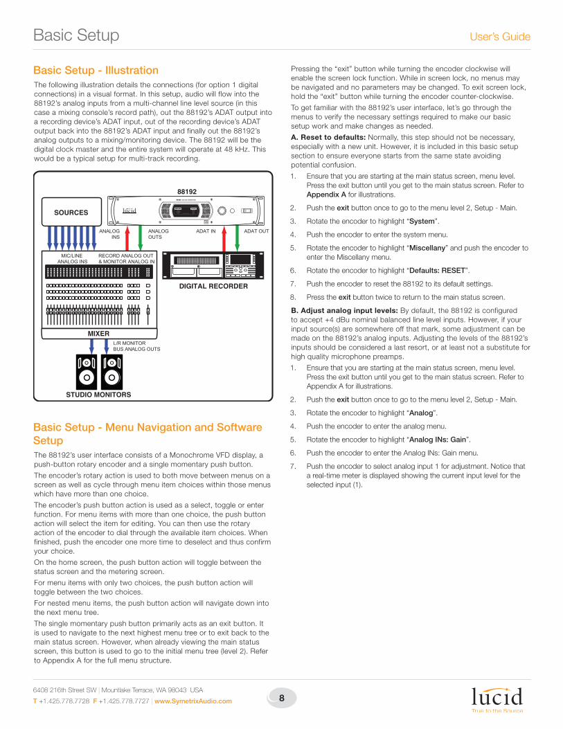
Basic Setup - IllustrationThe following illustration details the connections (for option 1 digital connections) in a visual format. In this setup, audio will flow into the 88192’s analog inputs from a multi-channel line level source (in this case a mixing console’s record path), out the 88192’s ADAT output into a recording device’s ADAT input, out of the recording device’s ADAT output back into the 88192’s ADAT input and finally out the 88192’s analog outputs to a mixing/monitoring device. The 88192 will be the digital clock master and the entire system will operate at 48 kHz. This would be a typical setup for multi-track recording.
Basic Setup - Menu Navigation and Software SetupThe 88192’s user interface consists of a Monochrome VFD display, a push-button rotary encoder and a single momentary push button.
The encoder’s rotary action is used to both move between menus on a screen as well as cycle through menu item choices within those menus which have more than one choice.
The encoder’s push button action is used as a select, toggle or enter function. For menu items with more than one choice, the push button action will select the item for editing. You can then use the rotary action of the encoder to dial through the available item choices. When finished, push the encoder one more time to deselect and thus confirm your choice.
On the home screen, the push button action will toggle between the status screen and the metering screen.
For menu items with only two choices, the push button action will toggle between the two choices.
For nested menu items, the push button action will navigate down into the next menu tree.
The single momentary push button primarily acts as an exit button. It is used to navigate to the next highest menu tree or to exit back to the main status screen. However, when already viewing the main status screen, this button is used to go to the initial menu tree (level 2). Refer to Appendix A for the full menu structure.
Pressing the “exit” button while turning the encoder clockwise will enable the screen lock function. While in screen lock, no menus may be navigated and no parameters may be changed. To exit screen lock, hold the “exit” button while turning the encoder counter-clockwise.
To get familiar with the 88192’s user interface, let’s go through the menus to verify the necessary settings required to make our basic setup work and make changes as needed.
A. Reset to defaults: Normally, this step should not be necessary, especially with a new unit. However, it is included in this basic setup section to ensure everyone starts from the same state avoiding potential confusion.
1. Ensure that you are starting at the main status screen, menu level. Press the exit button until you get to the main status screen. Refer to Appendix A for illustrations.
2. Push the exit button once to go to the menu level 2, Setup - Main.
3. Rotate the encoder to highlight “System”.
4. Push the encoder to enter the system menu.
5. Rotate the encoder to highlight “Miscellany” and push the encoder to enter the Miscellany menu.
6. Rotate the encoder to highlight “Defaults: RESET”.
7. Push the encoder to reset the 88192 to its default settings.
8. Press the exit button twice to return to the main status screen.
B. Adjust analog input levels: By default, the 88192 is configured to accept +4 dBu nominal balanced line level inputs. However, if your input source(s) are somewhere off that mark, some adjustment can be made on the 88192’s analog inputs. Adjusting the levels of the 88192’s inputs should be considered a last resort, or at least not a substitute for high quality microphone preamps.
1. Ensure that you are starting at the main status screen, menu level. Press the exit button until you get to the main status screen. Refer to Appendix A for illustrations.
2. Push the exit button once to go to the menu level 2, Setup - Main.
3. Rotate the encoder to highlight “Analog”.
4. Push the encoder to enter the analog menu.
5. Rotate the encoder to highlight “Analog INs: Gain”.
6. Push the encoder to enter the Analog INs: Gain menu.
7. Push the encoder to select analog input 1 for adjustment. Notice that a real-time meter is displayed showing the current input level for the selected input (1).
ADAT OUT
L/R MONITORBUS ANALOG OUTS
ADAT INANALOGOUTS
ANALOGINS
MIC/LINE ANALOG INS
RECORD ANALOG OUT & MONITOR ANALOG IN
SOURCES
MIXER
DIGITAL RECORDER
STUDIO MONITORS
88192
9
88192 A/D D/A Converter Basic Setup
8. Rotate the encoder to adjust the input gain for the selected input (1). The gain is adjusted in real time.
9. Push the encoder when finished to deselect the input.
10. Repeat steps 7-9 for any additional inputs needing adjustment.
11. Press the exit button three times to return to the main status screen.
C. Verify routing: By default, the 88192’s analog inputs are routed to the ADAT outputs and the ADAT inputs are routed to the analog outputs. To verify this, visit the routing menu using the following steps.
1. Ensure that you are starting at the main status screen, menu level. Press the exit button until you get to the main status screen. Refer to Appendix A for illustrations.
2. Push the exit button once to go to the menu level 2, Setup - Main.
3. Rotate the encoder to highlight “Route”.
4. Push the encoder to enter the routing menu.
5. Verify that “Analog INs ’ ADAT OUTs” and “ADAT INs ’ Analog OUTs” are both shown.
6. Press the exit button twice to return to the main status screen.
D. Adjust analog output levels: By default, the 88192 is configured to output +4 dBu nominal balanced line level outputs. However, if your destination device(s) expect something closer to a consumer -10 dBV nominal unbalanced line level, the 88192’s analog outputs can be adjusted to match.
1. Ensure that you are starting at the main status screen, menu level. Press the exit button until you get to the main status screen. Refer to Appendix A for illustrations.
2. Push the exit button once to go to the menu level 2, Setup - Main.
3. Rotate the encoder to highlight “Analog”.
4. Push the encoder to enter the analog menu.
5. Rotate the encoder to highlight “Analog OUTs: Level”.
6. Push the encoder to enter the Analog OUTs: Level menu.
7. Push the encoder to toggle analog output 1 between +4 and -10 output levels.
8. Rotate the encoder to select additional outputs for adjustment and push the encoder to toggle as necessary.
9. Press the exit button three times to return to the main status screen.
E. Adjust sample rate: By default, the 88192 is configured for a 44.1 kHz sample rate. For this basic setup, we want to use 48 kHz. The following steps detail changing the sample rate.
1. Ensure that you are starting at the main status screen, menu level. Press the exit button until you get to the main status screen. Refer to Appendix A for illustrations.
2. Push the exit button once to go to the menu level 2, Setup - Main.
3. Rotate the encoder to highlight “Sync”.
4. Push the encoder to enter the sync menu.
5. Push the encoder to select “Internal: 44.1 kHz”. Notice that “44.1 kHz” begins to flash indicating that it is selected for adjustment.
6. Rotate the encoder until “48 kHz” is displayed.
7. Push the encoder to confirm “48 kHz” as your choice. Notice that “48 kHz” is no longer flashing indicating that it is no longer selected for adjustment.
8. Press the exit button twice to return to the main status screen.
Basic Setup - ConclusionThis concludes the basic setup. If you have followed the previous Basic Setup sections completely, you should have the correct hardware connections and the 88192 should be set up correctly. Now, provided that you have your record sources, mixing console, recording device and monitor system set up correctly, you should be able to get signal flowing through the 88192 and get some recording done! Please consult the user’s manuals for your other devices to ensure they are set up correctly to work with the 88192. Do not forget to set your recording device to accept ADAT format digital inputs at 48 kHz and for the recording device to receive its digital sync from its ADAT inputs. Anytime there is a digital connection between devices, there can only be one “master” and all others must be “slaves” to it directly or indirectly. A master is the device to which all other devices sync. In short, your recording device should not be set to any type of “internal” sync unless you like listening to clicks and pops!
When all else fails...When you’re miserably lost, settings are completely out of whack or when you just want to make a fresh start, there is a factory reset function which will restore the 88192 to factory defaults.
WARNING! This process will completely erase all current settings contained in the 88192. Be sure that you
have documented any necessary settings (routing configurations, etc.) first!
Factory Initializing the 88192:1. From the home screen, navigate to menu level 9.1: Setup -
Miscellany (refer to Appendix A).
2. Rotate the encoder until “Defaults: RESET” is highlighted and push the encoder.
3. Press the exit button twice to return to the main status screen.
6408 216th Street SW | Mountlake Terrace, WA 98043 USA
T +1.425.778.7728 F +1.425.778.7727 | www.SymetrixAudio.com 10
User’s GuideApplications
To ANALOG INPUTS
From ANALOG OUTPUTSOptical(Toslink)Cables
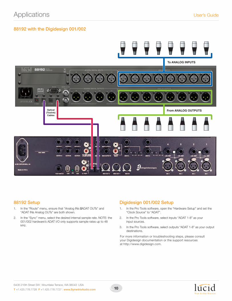
88192 with the Digidesign 001/002
88192 Setup1. In the “Route” menu, ensure that “Analog INs ADAT OUTs” and
“ADAT INs Analog OUTs” are both shown.
2. In the “Sync” menu, select the desired internal sample rate. NOTE: the 001/002 hardware’s ADAT I/O only supports sample rates up to 48 kHz.
Digidesign 001/002 Setup1. In the Pro Tools software, open the “Hardware Setup” and set the
“Clock Source” to “ADAT”.
2. In the Pro Tools software, select inputs “ADAT 1-8” as your input sources.
3. In the Pro Tools software, select outputs “ADAT 1-8” as your output destinations.
For more information or troubleshooting steps, please consult your Digidesign documentation or the support resources at http://www.digidesign.com.
11
88192 A/D D/A Converter Applications
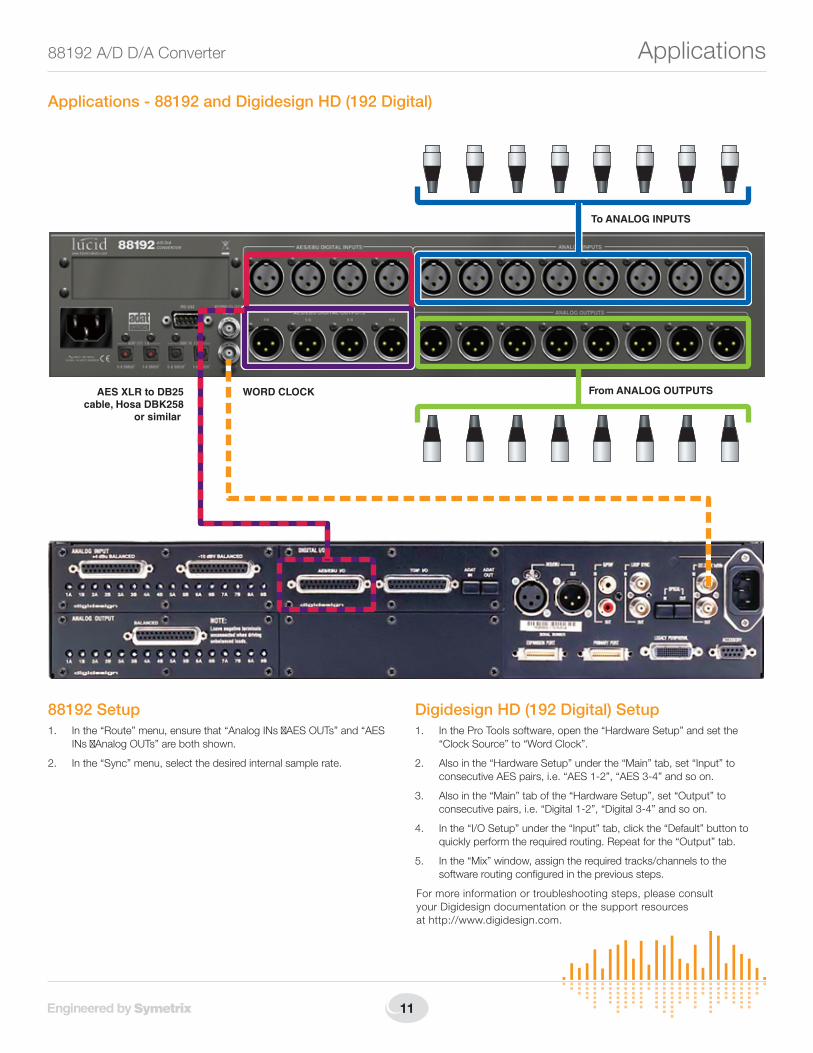
Applications - 88192 and Digidesign HD (192 Digital)
To ANALOG INPUTS
From ANALOG OUTPUTSWORD CLOCKAES XLR to DB25cable, Hosa DBK258
or similar
88192 Setup1. In the “Route” menu, ensure that “Analog INs AES OUTs” and “AES
INs Analog OUTs” are both shown.
2. In the “Sync” menu, select the desired internal sample rate.
Digidesign HD (192 Digital) Setup1. In the Pro Tools software, open the “Hardware Setup” and set the
“Clock Source” to “Word Clock”.
2. Also in the “Hardware Setup” under the “Main” tab, set “Input” to consecutive AES pairs, i.e. “AES 1-2”, “AES 3-4” and so on.
3. Also in the “Main” tab of the “Hardware Setup”, set “Output” to consecutive pairs, i.e. “Digital 1-2”, “Digital 3-4” and so on.
4. In the “I/O Setup” under the “Input” tab, click the “Default” button to quickly perform the required routing. Repeat for the “Output” tab.
5. In the “Mix” window, assign the required tracks/channels to the software routing configured in the previous steps.
For more information or troubleshooting steps, please consult your Digidesign documentation or the support resources at http://www.digidesign.com.
6408 216th Street SW | Mountlake Terrace, WA 98043 USA
T +1.425.778.7728 F +1.425.778.7727 | www.SymetrixAudio.com 12
User’s Guide
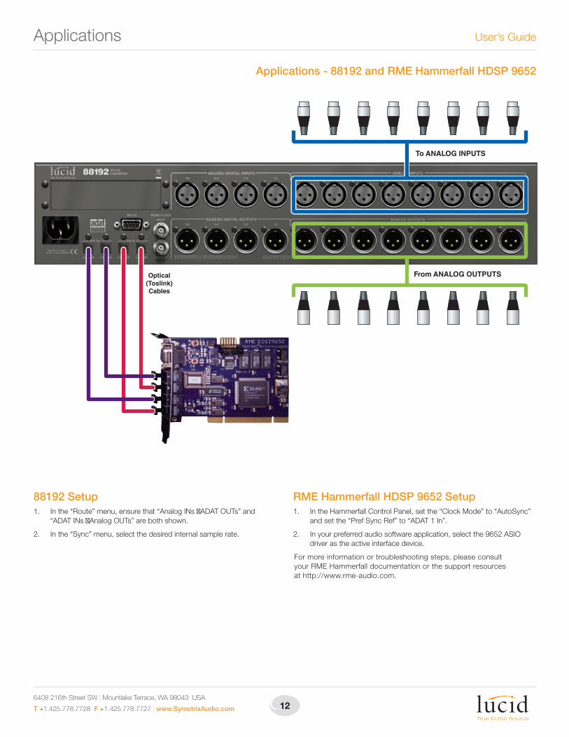
Applications - 88192 and RME Hammerfall HDSP 9652
To ANALOG INPUTS
From ANALOG OUTPUTSOptical(Toslink)Cables
88192 Setup1. In the “Route” menu, ensure that “Analog INs ADAT OUTs” and
“ADAT INs Analog OUTs” are both shown.
2. In the “Sync” menu, select the desired internal sample rate.
RME Hammerfall HDSP 9652 Setup1. In the Hammerfall Control Panel, set the “Clock Mode” to “AutoSync”
and set the “Pref Sync Ref” to “ADAT 1 In”.
2. In your preferred audio software application, select the 9652 ASIO driver as the active interface device.
For more information or troubleshooting steps, please consult your RME Hammerfall documentation or the support resources at http://www.rme-audio.com.
Applications
13
88192 A/D D/A Converter
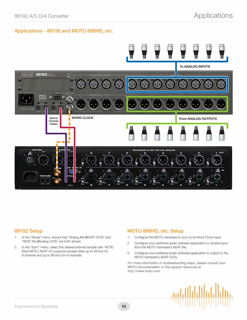
Applications - 88192 and MOTU 896HD, etc.
To ANALOG INPUTS
From ANALOG OUTPUTSWORD CLOCKOptical(Toslink)Cables
88192 Setup1. In the “Route” menu, ensure that “Analog INs ADAT OUTs” and
“ADAT INs Analog OUTs” are both shown.
2. In the “Sync” menu, select the desired internal sample rate. NOTE: Most MOTU ADAT I/O supports sample rates up to 48 kHz for 8-channel and up to 96 kHz for 4-channels.
MOTU 896HD, etc. Setup1. Configure the MOTU hardware to sync to its Word Clock input.
2. Configure your preferred audio software application to receive input from the MOTU hardware’s ADAT INs.
3. Configure your preferred audio software application to output to the MOTU hardware’s ADAT OUTs.
For more information or troubleshooting steps, please consult your MOTU documentation or the support resources at http://www.motu.com.
Applications
6408 216th Street SW | Mountlake Terrace, WA 98043 USA
T +1.425.778.7728 F +1.425.778.7727 | www.SymetrixAudio.com 14
User’s GuideAdvanced Features
Advanced FeaturesIt is inevitable you will come across a setup which does not fit into the examples detailed within the Basic Setup or example Applications sections. For those cases, the 88192 has a few deeper settings to accommodate.
SoftClip:SoftClip is available on each analog input pair. SoftClip can help reduce occurrences of those nasty “digital overs” during peak transients by gently “rounding them off”. SoftClip should not be used as a substitute for a quality analog compressor/limiter, however. SoftClip can be toggled on and off in the setup menu, level 5.1. Refer to Appendix A.
Sample Rate Conversion:Sample Rate Conversion (SRC) is available on all digital inputs. When SRC is enabled for the ADAT INs, it is applied to all eight channels. For AES INs, SRC can be enabled per input pair. SRC can be toggled on and off in the ADAT and AES setup menus, level 3 and 4 respectively. Refer to Appendix A.
SRC is necessary when the sample rate of all digital inputs cannot be absolutely guaranteed. This is commonly encountered when accepting digital inputs from different devices, some or all of which do not have the ability to lock to a common sync source (e.g. Word Clock).
SRC is also commonly used to accommodate inputs from devices which must operate at a clock rate different than the 88192, i.e. the 88192 is operating at 44.1 kHz while accepting AES input from a DAT machine operating at 48 kHz.
NOTE: SRC is enabled by default as a convenience. If you can guarantee that all of your digital inputs to the 88192 are locked to the sample rate the 88192 is using, SRC can be safely turned off.
Routing in Pairs:Until now, the provided setups have assumed octet (groups of eight) routing. For those times when the 88192 may be accepting sources consisting of less than eight channels from multiple devices, even in different formats, the Pair Routing options must be used. Routing in Pairs is enabled in the System Setup menu, level 9.1. Toggle the Routing Unit option to “2 chs”. This will expose a much more complex Routing menu (see Appendix A, menu level 7). You will now have the ability to route any input pair to any output pair, even across formats.
NOTE: When using Pair Routing, the use of SRC is highly recommended due to the fact that this type of routing usually incorporates sources from different devices. It can be difficult to guarantee sample frequency synchronization of the various inputs.
External Sync:Until now, the provided setups have assumed the 88192 is the clock master in the system. For those times when the 88192 is incorporated into an existing setup with a dedicated master clock, or for those times when the 88192 just must be synchronized to another device, the 88192 can sync to any sample rate between 30 and 200 kHz via its Word Clock, AES or ADAT inputs. (The 88192 can only sync to sample rates up to 100 kHz via ADAT.) To sync to an external device or clock, navigate to the Sync Setup menu (see Appendix A, menu level 8). Rotate the encoder to select “External:” and push the encoder to edit. Rotate the encoder in order to sync to either Word Clock, ADAT IN, or an AES input pair.
NOTE 1: When external sync is enabled, internal is automatically disabled and vice versa.
NOTE 2: The Sync menu will display the incoming sync rate and the lock status. This can be very useful for diagnostics! The locked status, sample rate and sync source are also visible on the main status screen (see Appendix A, menu level 1).
SMUX IN/OUT:The SMUX IN mode must be manually set when using eight channels of ADAT SMUX2 input (at sample rates between 50 and 100 kHz). SMUX IN mode can be toggled on and off in the ADAT setup menu, level 3. Refer to Appendix A. SMUX OUT mode is automatically set depending upon sample rate. If the sample rate is greater than 50 kHz, SMUX OUT is ON.
Metering:Full user control is provided over metering. From the main status screen, simply rotate the encoder to cycle through the available metering sources (see Appendix A, menu level 1). Pressing the encoder will toggle between system status indications and meter scale indications. Control over clip hold and peak hold times is also provided. Clip detect threshold (see Appendix A, menu level 6) determines the number of consecutive full-scale samples that must occur before the signal is considered clipped (or before a clip is registered).
15
88192 A/D D/A Converter Appendix A - Hardware Menu Structure
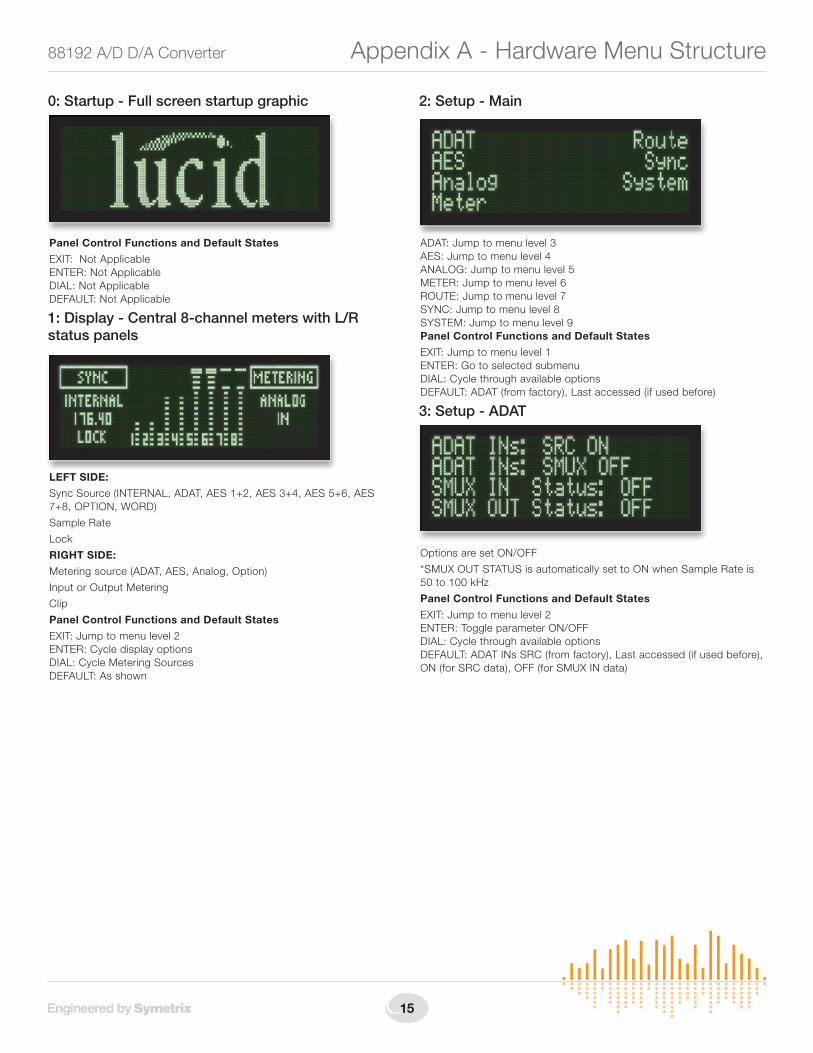
0: Startup - Full screen startup graphic
Panel Control Functions and Default States
EXIT: Not Applicable ENTER: Not Applicable DIAL: Not Applicable DEFAULT: Not Applicable
1: Display - Central 8-channel meters with L/R status panels
LEFT SIDE:
Sync Source (INTERNAL, ADAT, AES 1+2, AES 3+4, AES 5+6, AES 7+8, OPTION, WORD)
Sample Rate
Lock
RIGHT SIDE:
Metering source (ADAT, AES, Analog, Option)
Input or Output Metering
Clip
Panel Control Functions and Default States
EXIT: Jump to menu level 2 ENTER: Cycle display options DIAL: Cycle Metering Sources DEFAULT: As shown
2: Setup - Main
ADAT: Jump to menu level 3 AES: Jump to menu level 4 ANALOG: Jump to menu level 5 METER: Jump to menu level 6 ROUTE: Jump to menu level 7 SYNC: Jump to menu level 8 SYSTEM: Jump to menu level 9 Panel Control Functions and Default States
EXIT: Jump to menu level 1 ENTER: Go to selected submenu DIAL: Cycle through available options DEFAULT: ADAT (from factory), Last accessed (if used before)
3: Setup - ADAT
Options are set ON/OFF
*SMUX OUT STATUS is automatically set to ON when Sample Rate is 50 to 100 kHz
Panel Control Functions and Default States
EXIT: Jump to menu level 2 ENTER: Toggle parameter ON/OFF DIAL: Cycle through available options DEFAULT: ADAT INs SRC (from factory), Last accessed (if used before), ON (for SRC data), OFF (for SMUX IN data)
6408 216th Street SW | Mountlake Terrace, WA 98043 USA
T +1.425.778.7728 F +1.425.778.7727 | www.SymetrixAudio.com 16
User’s GuideAppendix A - Hardware Menu Structure
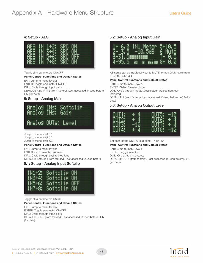
4: Setup - AES
Toggle all 4 parameters ON/OFF
Panel Control Functions and Default States
EXIT: Jump to menu level 2 ENTER: Toggle parameter ON/OFF DIAL: Cycle through input pairs DEFAULT: AES IN1+2 (from factory), Last accessed (if used before), ON (for data)
5: Setup - Analog Main
Jump to menu level 5.1 Jump to menu level 5.2 Jump to menu level 5.3
Panel Control Functions and Default States
EXIT: Jump to menu level 2 ENTER: Go to selected submenu DIAL: Cycle through available options DEFAULT: SoftClip ( from factory), Last accessed (if used before)
5.1: Setup - Analog Input Softclip
Toggle all 4 parameters ON/OFF
Panel Control Functions and Default States
EXIT: Jump to menu level 5 ENTER: Toggle parameter ON/OFF DIAL: Cycle through input pairs DEFAULT: IN1+2 (from factory), Last accessed (if used before), ON (for data)
5.2: Setup - Analog Input Gain
All inputs can be individually set to MUTE, or at a GAIN levels from -95.5 to +31.5 dB
Panel Control Functions and Default States
EXIT: Jump to menu level 5 ENTER: Select/deselect input DIAL: Cycle through inputs (deselected), Adjust input gain (selected) DEFAULT: 1 (from factory), Last accessed (if used before), +0.0 (for data)
5.3: Setup - Analog Output Level
Set each of the OUTPUTs at either +4 or -10
Panel Control Functions and Default States
EXIT: Jump to menu level 5 ENTER: Toggle selection DIAL: Cycle through outputs DEFAULT: OUT1 (from factory), Last accessed (if used before), +4 (for data)
17
88192 A/D D/A Converter Appendix A - Hardware Menu Structure
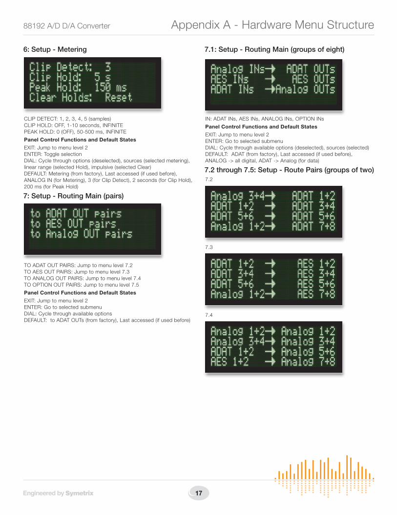
6: Setup - Metering
CLIP DETECT: 1, 2, 3, 4, 5 (samples) CLIP HOLD: OFF, 1-10 seconds, INFINITE PEAK HOLD: 0 (OFF), 50-500 ms, INFINITE
Panel Control Functions and Default States
EXIT: Jump to menu level 2 ENTER: Toggle selection DIAL: Cycle through options (deselected), sources (selected metering), linear range (selected Hold), impulsive (selected Clear) DEFAULT: Metering (from factory), Last accessed (if used before), ANALOG IN (for Metering), 3 (for Clip Detect), 2 seconds (for Clip Hold), 200 ms (for Peak Hold)
7: Setup - Routing Main (pairs)
TO ADAT OUT PAIRS: Jump to menu level 7.2 TO AES OUT PAIRS: Jump to menu level 7.3 TO ANALOG OUT PAIRS: Jump to menu level 7.4 TO OPTION OUT PAIRS: Jump to menu level 7.5
Panel Control Functions and Default States
EXIT: Jump to menu level 2 ENTER: Go to selected submenu DIAL: Cycle through available options DEFAULT: to ADAT OUTs (from factory), Last accessed (if used before)
7.1: Setup - Routing Main (groups of eight)
IN: ADAT INs, AES INs, ANALOG INs, OPTION INs
Panel Control Functions and Default States
EXIT: Jump to menu level 2 ENTER: Go to selected submenu DIAL: Cycle through available options (deselected), sources (selected) DEFAULT: ADAT (from factory), Last accessed (if used before), ANALOG -> all digital, ADAT -> Analog (for data)
7.2 through 7.5: Setup - Route Pairs (groups of two)7.2
7.3
7.4
6408 216th Street SW | Mountlake Terrace, WA 98043 USA
T +1.425.778.7728 F +1.425.778.7727 | www.SymetrixAudio.com 18
User’s Guide
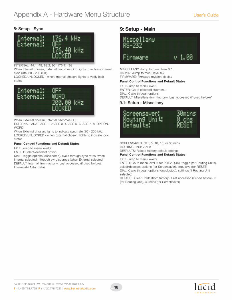
8: Setup - Sync
INTERNAL: 44.1, 48, 88.2, 96, 176.4, 192 When Internal chosen, External becomes OFF, lights to indicate internal sync rate (30 - 200 kHz) LOCKED/UNLOCKED - when Internal chosen, lights to verify lock status
When External chosen, Internal becomes OFF EXTERNAL: ADAT, AES 1+2, AES 3+4, AES 5+6, AES 7+8, OPTION, WORD When External chosen, lights to indicate sync rate (30 - 200 kHz) LOCKED/UNLOCKED - when External chosen, lights to indicate lock status
Panel Control Functions and Default States
EXIT: Jump to menu level 2 ENTER: Select/deselect option DIAL: Toggle options (deselected), cycle through sync rates (when Internal selected), through sync sources (when External selected) DEFAULT: Internal (from factory), Last accessed (if used before), Internal/44.1 (for data)
9: Setup - Main
MISCELLANY: Jump to menu level 9.1 RS-232: Jump to menu level 9.2 FIRMWARE: Firmware revision display
Panel Control Functions and Default States
EXIT: Jump to menu level 2 ENTER: Go to selected submenu DIAL: Cycle through options DEFAULT: Miscellany (from factory), Last accessed (if used before)”
9.1: Setup - Miscellany
SCREENSAVER: OFF, 5, 10, 15, or 30 mins ROUTING UNIT: 2 or 8 DEFAULTS: Reload factory default settings Panel Control Functions and Default States
EXIT: Jump to menu level 9 ENTER: Go to menu level 9 (for PREVIOUS), toggle (for Routing Units), select/deselect options (for Screensaver), impulsive (for RESET) DIAL: Cycle through options (deselected), settings (if Routing Unit selected) DEFAULT: Clear Holds (from factory), Last accessed (if used before), 8 (for Routing Unit), 30 mins (for Screensaver)
Appendix A - Hardware Menu Structure
19
88192 A/D D/A Converter
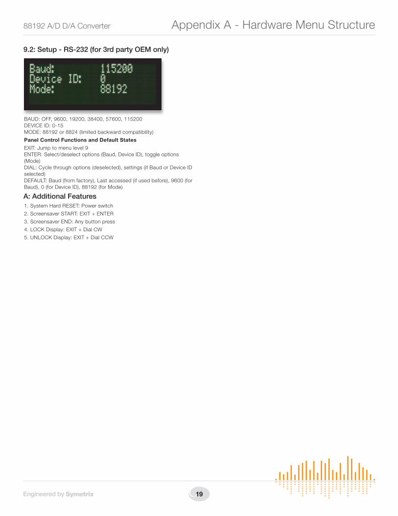
9.2: Setup - RS-232 (for 3rd party OEM only)
BAUD: OFF, 9600, 19200, 38400, 57600, 115200 DEVICE ID: 0-15 MODE: 88192 or 8824 (limited backward compatibility)
Panel Control Functions and Default States
EXIT: Jump to menu level 9 ENTER: Select/deselect options (Baud, Device ID), toggle options (Mode) DIAL: Cycle through options (deselected), settings (if Baud or Device ID selected) DEFAULT: Baud (from factory), Last accessed (if used before), 9600 (for Baud), 0 (for Device ID), 88192 (for Mode)
A: Additional Features1. System Hard RESET: Power switch
2. Screensaver START: EXIT + ENTER
3. Screensaver END: Any button press
4. LOCK Display: EXIT + Dial CW
5. UNLOCK Display: EXIT + Dial CCW
Appendix A - Hardware Menu Structure
6408 216th Street SW | Mountlake Terrace, WA 98043 USA
T +1.425.778.7728 F +1.425.778.7727 | www.SymetrixAudio.com 20
User’s Guide
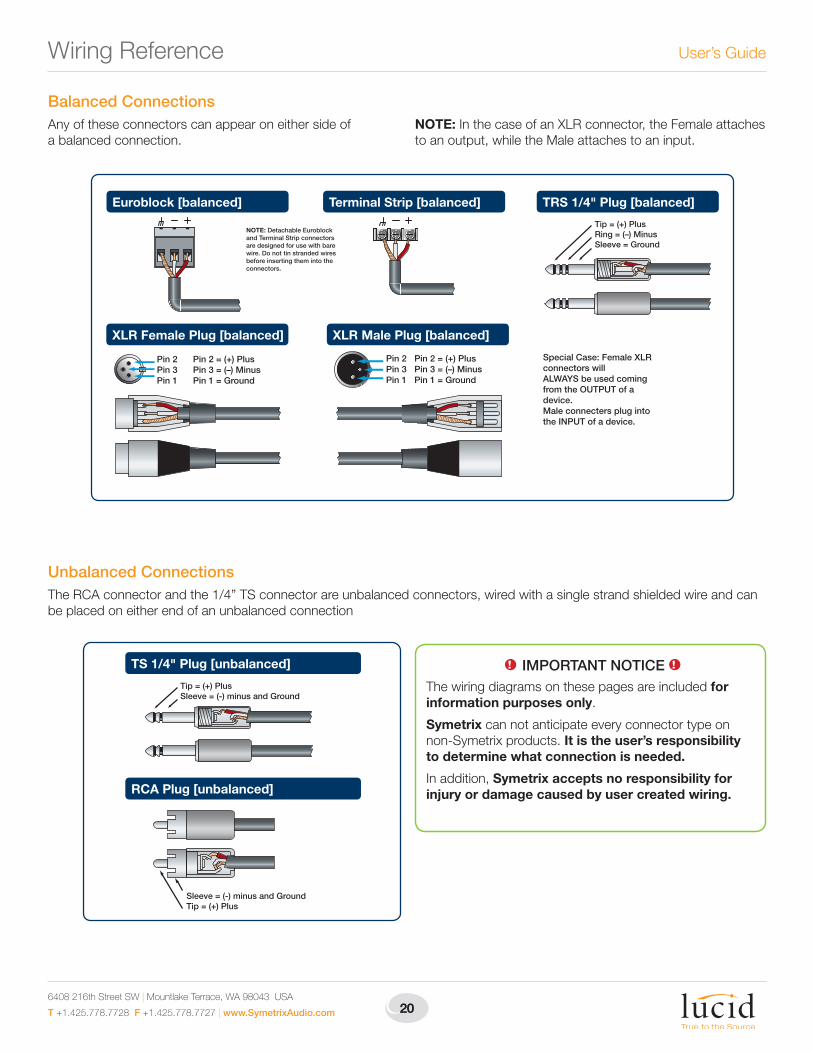
XLR Male Plug [balanced]
Pin 2Pin 3Pin 1
Pin 2 = (+) PlusPin 3 = (–) MinusPin 1 = Ground
XLR Female Plug [balanced]
Pin 2 = (+) PlusPin 3 = (–) MinusPin 1 = Ground
Pin 2Pin 3Pin 1
Terminal Strip [balanced] TRS 1/4" Plug [balanced]
Tip = (+) PlusRing = (–) MinusSleeve = Ground
Euroblock [balanced]
NOTE: Detachable Euroblock and Terminal Strip connectors are designed for use with bare wire. Do not tin stranded wires before inserting them into the connectors.
Special Case: Female XLR connectors willALWAYS be used coming from the OUTPUT of a device.Male connecters plug into the INPUT of a device.
Balanced ConnectionsAny of these connectors can appear on either side of a balanced connection.
NOTE: In the case of an XLR connector, the Female attaches to an output, while the Male attaches to an input.
Unbalanced ConnectionsThe RCA connector and the 1/4” TS connector are unbalanced connectors, wired with a single strand shielded wire and can be placed on either end of an unbalanced connection
TS 1/4" Plug [unbalanced]
Tip = (+) PlusSleeve = (-) minus and Ground
RCA Plug [unbalanced]
Sleeve = (-) minus and GroundTip = (+) Plus
1! IMPORTANT NOTICE 1!
The wiring diagrams on these pages are included for information purposes only.
Symetrix can not anticipate every connector type on non-Symetrix products. It is the user’s responsibility to determine what connection is needed.
In addition, Symetrix accepts no responsibility for injury or damage caused by user created wiring.
Wiring Reference
21
88192 A/D D/A Converter Wiring Reference
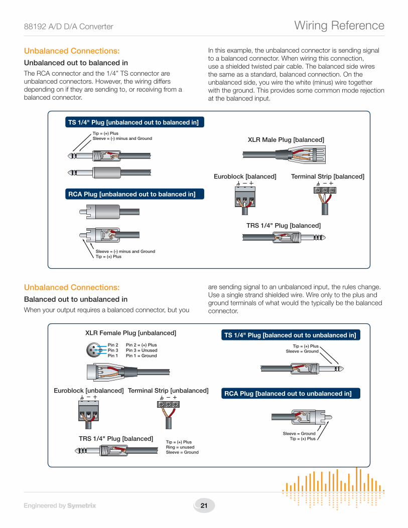
Unbalanced Connections:Unbalanced out to balanced inThe RCA connector and the 1/4” TS connector are unbalanced connectors. However, the wiring differs depending on if they are sending to, or receiving from a balanced connector.
In this example, the unbalanced connector is sending signal to a balanced connector. When wiring this connection, use a shielded twisted pair cable. The balanced side wires the same as a standard, balanced connection. On the unbalanced side, you wire the white (minus) wire together with the ground. This provides some common mode rejection at the balanced input.
Unbalanced Connections:Balanced out to unbalanced inWhen your output requires a balanced connector, but you
are sending signal to an unbalanced input, the rules change. Use a single strand shielded wire. Wire only to the plus and ground terminals of what would the typically be the balanced connector.
XLR Male Plug [balanced]
TS 1/4" Plug [unbalanced out to balanced in]
TRS 1/4" Plug [balanced]
Euroblock [balanced]
Tip = (+) PlusSleeve = (-) minus and Ground
RCA Plug [unbalanced out to balanced in]
Sleeve = (-) minus and GroundTip = (+) Plus
Terminal Strip [balanced]
TS 1/4" Plug [balanced out to unbalanced in]
Tip = (+) PlusSleeve = Ground
RCA Plug [balanced out to unbalanced in]
Sleeve = GroundTip = (+) Plus
Euroblock [unbalanced] Terminal Strip [unbalanced]
XLR Female Plug [unbalanced]
Pin 2 = (+) PlusPin 3 = UnusedPin 1 = Ground
Pin 2Pin 3Pin 1
TRS 1/4" Plug [balanced]Tip = (+) PlusRing = unusedSleeve = Ground
6408 216th Street SW | Mountlake Terrace, WA 98043 USA
T +1.425.778.7728 F +1.425.778.7727 | www.SymetrixAudio.com 22
User’s GuideStatement of Conformity
Declaration of ConformityWe, Symetrix Inc.,
6408 216th St. SW, Mountlake Terrace, Washington, USA, declare under our sole responsibility that the product:
88192 A/D D/A Converter
to which this declaration relates, is in conformity with the following standards:
EN 60065
Safety requirements for mains operated electronic and related
apparatus for household and similar general use.
EN 55103-1
Electromagnetic compatibility - Generic emission standard
Part 1: Residential, commercial, and light industry.
EN 55103-2
Electromagnetic compatibility - Generic immunity standard
Part 1: Residential, commercial, and light industry.
The technical construction file is maintained at:
Symetrix, Inc.
6408 216th St. SW
Mountlake Terrace, WA, 98043
USA
The authorized representative located within the European Community is:
World Marketing Associates
P.O. Box 100
St. Austell, Cornwall, PL26 6YU, U.K.
Date of issue: January 06, 2006
Place of issue: Mountlake Terrace, Washington, USA
Authorized signature:
Dane Butcher, President, Symetrix Incorporated.
23
88192 A/D D/A Converter Warranty and Service
The Symetrix Limited WarrantySymetrix, Inc. expressly warrants that the product will be free from defects in material and workmanship for eighteen (18) months from the date the product is shipped from the factory. Symetrix’s obligations under this warranty will be limited to repairing or replacing, at Symetrix’s option, the part or parts of the product which prove defective in material or workmanship within two (2) years from the date the product is shipped from the factory, provided that the Buyer gives Symetrix prompt notice of any defect or failure and satisfactory proof thereof. Products may be returned by Buyer only after a Return Authorization number (RA) has been obtained from Symetrix. Buyer will prepay all freight charges to return the product to the Symetrix factory. Symetrix reserves the right to inspect any products which may be the subject of any warranty claim before repair or replacement is carried out. Symetrix may, at its option, require proof of the original date of purchase (dated copy of original retail dealer’s invoice). Final determination of warranty coverage lies solely with Symetrix. Products repaired under warranty will be returned freight prepaid via United Parcel Service by Symetrix, to any location within the Continental United States. Outside the Continental United States, products will be returned freight collect.
The foregoing warranties are in lieu of all other warranties, whether oral, written, express, implied or statutory. Symetrix, Inc. expressly disclaims any IMPLIED warranties, including fitness for a particular purpose or merchantability. Symetrix’s warranty obligation and buyer’s remedies hereunder are SOLELY and exclusively as stated herein.
This Symetrix product is designed and manufactured for use in professional and studio audio systems and is not intended for other usage. With respect to products purchased by consumers for personal, family, or household use, Symetrix expressly disclaims all implied warranties, including but not limited to warranties of merchantability and fitness for a particular purpose.
This limited warranty, with all terms, conditions and disclaimers set forth herein, shall extend to the original purchaser and anyone who purchases the product within the specified warranty period.
Symetrix does not authorize any third party, including any dealer or sales representative, to assume any liability or make any additional warranties or representation regarding this product information on behalf of Symetrix.
This limited warranty gives the buyer certain rights. You may have additional rights provided by applicable law.
Note: Some Symetrix products contain embedded software and may also be accompanied by control software intended to be run on a personal computer. Said software is specifically excluded from this warranty.
Limitation of LiabilityThe total liability of Symetrix on any claim, whether in contract, tort (including negligence) or otherwise arising out of, connected with, or resulting from the manufacture, sale, delivery, resale, repair, replacement or use of any product will not exceed the price allocatable to the product or any part thereof which gives rise to the claim. In no event will Symetrix be liable for any incidental or consequential damages including but not limited to damage for loss of revenue, cost of capital, claims of customers for service interruptions or failure to supply, and costs and expenses incurred in connection with labor, overhead, transportation, installation or removal of products, substitute facilities or supply houses.
Servicing Your Symetrix Product
If you have determined that your Symetrix product requires repair services and you live outside of the United States please contact your local Symetrix dealer or distributor for instructions on how to obtain service. If you reside in the U.S. then proceed as follows:
Return AuthorizationAt the Symetrix factory, Symetrix will perform in-warranty or out-of-warranty service on any product it has manufactured for a period of three (3) years from date of discontinued manufacture.
Before sending anything to Symetrix, please contact our Customer Service Department for a Return Authorization (RA) number. The telephone number is +1.425.778.7728. Additionally, support is available via the web site: http://support.SymetrixAudio.com.
In-warranty RepairsTo get your Symetrix product repaired under the terms of the warranty:
1. Call us for an RA number (have the serial number, shipping and contact information and description of the problem ready).
2. Pack the unit in its original packaging materials.
3. Include your name, address, daytime telephone number, and a brief statement of the problem.
4. Write the RA number on the outside of the box.
5. Ship the unit to Symetrix, freight prepaid. We do not accept freight collect shipments.
Just do these five things, and repairs made in-warranty will cost you only one way freight charges. We’ll pay the return freight.
If you don’t have the factory packaging materials, we recommend using an oversize box. Wrap the unit in a plastic bag, surround it with bubble-wrap, and place it in the box surrounded by Styrofoam peanuts. Be sure there is enough clearance in the box to protect the rack ears. We won’t return the unit in anything but Symetrix packaging for which we will have to charge you. If the problem is due to operator misuse or error, you will have to pay for both parts and labor. In any event, if there are charges for the repair, you will pay for the return freight. All charges will be COD unless you have made other arrangements (prepaid, Visa or Mastercard).
Out-of-warranty RepairsIf the warranty period has passed, you’ll be billed for all necessary parts, labor, packaging materials, and freight charges. Please remember, you must call for an RA number before sending the unit to Symetrix.
6408 216th Street SW | Mountlake Terrace, WA 98043 USA
T +1.425.778.7728 F +1.425.778.7727 | www.SymetrixAudio.com
Item No. 53-0015
88192 A/D D/A Converter User’s Guide
© 2009 Symetrix, Inc. All rights reserved. Printed in the United States of America. The information in this document is subject to change without notice. Symetrix, Inc. shall not be liable for technical or editorial errors or omissions contained herein; nor is it liable for incidental or consequential damages resulting from the furnishing, performance, or use of this material. Mention of third-party products is for informational purposes only and constitutes neither an endorsement nor a recommendation. Symetrix assumes no responsibility with regard to the performance or use of these products. Under copyright laws, no part of this brochure may be reproduced or transmitted in any form or by any means, electronic or mechanical, without permission in writing from Symetrix, Inc. If, however, your only means of access is electronic, permission to print one copy is hereby granted. The following are either Trademarks or Registered Trademarks of Symetrix, Inc.: Symetrix, SymNet, SymNet Designer, SymLink and CobraLink. Windows is a Registered Trademark of Microsoft, Inc.. Other product names mentioned herein may be trademarks and/or registered trademarks of other companies and are property of their respective owners.