‘99 ’11 chevrolet/gmc - performancelifts.com · rcd suspension 619-588-4723...
TRANSCRIPT

www.racecardynamics.com RCD Suspension 619-588-4723 [email protected]
Page 1 - #16-41899
‘99-’11 CHEVROLET/GMC
IFS 4WD (8-LUG) 6” SUSPENSION SYSTEM
P/N. 10-41899 &
‘99-’11 CHEVROLET/GMC IFS 2WD (8-LUG)
6” SUSPENSION SYSTEM P/N. 10-41299
INSTALLATION INSTRUCTIONS
NOTE: Each Lift Kit, and options to Lift Kits are packaged separately. Therefore installation procedures are covered in separate instructions. Familiarize yourself with each set of instructions before beginning.
4/10/13

www.racecardynamics.com RCD Suspension 619-588-4723 [email protected]
Page 2 - #16-41899
Parts List Item Description Qty Illus. Box 1 of 5 (41299 & 41899) 20-51899-1 Front Crossmember 1 11 20-51899-2 Rear Crossmember 1 11 Box 2 of 5 (41299 & 41899) 20-51800-5D Front Spindles (Drvr.) 1 20-51800-6P Front Spindles (Pass.) 1 Box 3 of 5 (41299 & 41899) 20-51899-9 Lateral Compression Struts 2 14 20-51099-22 Bracket, Strut Mount 2 14 20-68409 Hardware Pack Containing: (Bushing Bag) 15-11148 Bushing, Red 8 14 20-830918 Sleeve, ¾” x 2 ¾” 4 14 20-832868 Sleeve, ¾” x 1 ½” 2 14 20-67902 Hardware Pack Containing: (Compression Strut) 13-20069-Z Hex Bolt, ½” – 13 x 4” Lg. 4 14 13-21014-Z Hex Bolt, ½” - 13 x 3” Lg. 2 14 13-30034-Z Flat Washer, ½” SAE 12 14 13-10038-Z Nyloc Nut, ½” – 13 6 14 Box 4 of 5 (41899 ONLY) 20-51899-3 Bracket, Torsion Bar Drop 2 15 20-51899-7 Bracket, Differential Support 1 9 20-51899-8 Bracket, Differential Drop 1 10 20-830658 Block, Tapered Rear 4” 2 17 20-68383 Hardware Pack Containing: (Drive Axle Spacer) 13-22769-Z Hex Bolt, 10mm x 1.5 x 50mm Gr. 10.9 12 12 13-30642-z Flat Washer, 10mm Hrdn. 12 12 13-90490 Loctite #262 1 20-51899-20 Spacer, Drive Axle (8-Lug) 2 12 20-67850 Hardware Pack Containing (Torsion Bar Drop) 13-21118-Z Hex Bolt, 7/16” – 14 x 1 ¼” Lg. Gr. 8 8 15 13-30304-Z Flat Washer, 7/16” Hdrn. 16 15 13-10384-Z Top Lock Nut, 7/16” – 14 Gr. C 8 15 15-11174 Bushing, Red 4 15 20-832257 Sleeve, ¾” x 1.52” Lg. 2 15

www.racecardynamics.com RCD Suspension 619-588-4723 [email protected]
Page 3 - #16-41899
20-68396 Hardware Pack: (Differential Support & Drop)
13-22665-Z Hex Bolt, 9/16” – 12 x 1 ¾” Lg. Gr. 8 2 10 13-22704-Z Hex Bolt, 7/16” – 14 x 3” Lg. Gr. 8 1 9 13-22639-Z Bolt, 10mm x 1.5 x 60mm Lg. Gr. 10.9 5 9 13-30395-Z Flat Washer, 9/16” Hrdn. 4 10 13-30304-Z Flat Washer, 7/16” Hrdn. 2 9 13-30642-Z Flat Washer, 10mm Hrdn. 5 9 13-10397-Z Top Lock Nut, 9/16” – 12 Gr. C 2 10 13-10384-Z Top Lock Nut, 7/16” – 14 Gr. C 1 15-11148 Bushing, Red 2 9 20-832725 Sleeve, ¾” x 2 ¼” Lg. 1 9 20-69917 Hardware Pack Containing: (Sway Bar 9 ½” Extension) 20-833739 Sway Bar Extension (9 ½”) 2 16 13-22743-Z Button Head, ½” – 13 x 3” Lg. 2 16 13-30694-Z Washer, Bushing Retainer 1-1/4” 2 16 13-10878-Z Nyloc Nut, 1/2”-20 2 16 15-11616 Bushing, Sway Bar Link Inner 2 16 15-11629 Bushing, Sway Bar Link Outer 2 16 15-11746 Bushing, Sway Bar Flex Joint 4 16 20-68435 Hardware Pack Containing: (Front & Rear Crossmember)
13-21950-Z Hex Bolt, 5/8” – 11 x 5 ½” Gr. 8 2 13-22028-Z Hex Bolt, 5/8” – 11 x 4 ½” Gr. 8 2 13-20031-Z Hex Bolt, ½” – 13 x 1 ¼” 2 13-20320-Z Hex Bolt, 3/8” – 16x 2” 2 13-30369-Z Flat Washer, 5/8” Hrdn. 8 13-30012-Z Flat Washer, 3/8” SAE 4 13-10345-Z Top Lock Nut 5/8” – 11 Gr. C 4 13-1022-Z Nyloc Nut, 3/8” – 16 2 20-830866 Spacer, Locating 1.85” x 2.81” 1 11-15144 Tube, 1” x 5/16” 2 20-68279 Hardware Pack Containing: (Rear Bumpstop & Brakeline) 20-51292-14 Rear, Brake Line Extension 1 20-51292-15 Rear, Bumpstop Extension 2 13-20081-Z Hex Bolt, 3/8” – 16 x 1 ¼” Lg. 4 13-20536-Z Hex Bolt, 5/16” – 18 x 1” Lg. 2 13-30012-Z Flat Washer, 3/8” SAE 8 13-30187-Z Flat Washer, 5/16” SAE 4 13-10022-Z Nyloc Nut, 3/8” – 16 4 13-10155-Z Nyloc Nut, 5/16” – 18 2 20-65471 Hardware Pack Containing: (U-bolt Hardware) 13-30369 Flat Washer, 5/8” Hrdn. 8 17 13-10488 High Nut, 5/8” – 18 8 17 20-68305 Hardware Pack Containing: (RCD Universal) 13-20447-Z Unslot Hex, #10 x ½” 4 15-10966 Clamp, 3/8” x 3/8” x .203” 4 15-11395 Wire Tie, 6” 4 15-1147 Wire Tie, 8” 2 15-11460 Wire Tie, 11” 2

www.racecardynamics.com RCD Suspension 619-588-4723 [email protected]
Page 4 - #16-41899
20-830554 Cap, Frame 4” x 4” 1 7 13-90347 U-Bolt, 5/8” – 18 x 14” 4 17 Box 4 of 5 (41299 ONLY) 20-51899-3 Bracket, Torsion Bar Drop 2 15 20-830658 Block, Tapered Rear 4” 2 17 20-67850 Hardware Pack Containing (Torsion Bar Drop) 13-21118-Z Hex Bolt, 7/16” – 14 x 1 ¼” Lg. Gr. 8 8 15 13-30304-Z Flat Washer, 7/16” Hdrn. 16 15 13-10384-Z Top Lock Nut, 7/16” – 14 Gr. C 8 15 15-11174 Bushing, Red 4 15 20-832257 Sleeve, ¾” x 1.52” Lg. 2 15 20-69917 Hardware Pack Containing: (Sway Bar 9 ½” Extension) 20-833739 Sway Bar Extension (9 ½”) 2 16 13-22743-Z Button Head, ½” – 13 x 3” Lg. 2 16 13-30694-Z Washer, Bushing Retainer 1-1/4” 2 16 13-10878-Z Nyloc Nut, 1/2”-20 2 16 15-11616 Bushing, Sway Bar Link Inner 2 16 15-11629 Bushing, Sway Bar Link Outer 2 16 15-11746 Bushing, Sway Bar Flex Joint 4 16 20-68435 Hardware Pack Containing: (Front & Rear Crossmember)
13-21950-Z Hex Bolt, 5/8” – 11 x 5 ½” Gr. 8 2 13-22028-Z Hex Bolt, 5/8” – 11 x 4 ½” Gr. 8 2 13-20031-Z Hex Bolt, ½” – 13 x 1 ¼” 2 13-20320-Z Hex Bolt, 3/8” – 16x 2” 2 13-30369-Z Flat Washer, 5/8” Hrdn. 8 13-30012-Z Flat Washer, 3/8” SAE 4 13-10345-Z Top Lock Nut 5/8” – 11 Gr. C 4 13-1022-Z Nyloc Nut, 3/8” – 16 2 20-830866 Spacer, Locating 1.85” x 2.81” 1 11-15144 Tube, 1” x 5/16” 2 20-68279 Hardware Pack Containing: (Rear Bumpstop & Brakeline) 20-51292-14 Rear, Brake Line Extension 1 20-51292-15 Rear, Bumpstop Extension 2 13-20081-Z Hex Bolt, 3/8” – 16 x 1 ¼” Lg. 4 13-20536-Z Hex Bolt, 5/16” – 18 x 1” Lg. 2 13-30012-Z Flat Washer, 3/8” SAE 8 13-30187-Z Flat Washer, 5/16” SAE 4 13-10022-Z Nyloc Nut, 3/8” – 16 4 13-10155-Z Nyloc Nut, 5/16” – 18 2 20-65471 Hardware Pack Containing: (U-bolt Hardware) 13-30369 Flat Washer, 5/8” Hrdn. 8 17 13-10488 High Nut, 5/8” – 18 8 17 20-68305 Hardware Pack Containing: (RCD Universal) 13-20447-Z Unslot Hex, #10 x ½” 4 15-10966 Clamp, 3/8” x 3/8” x .203” 4

www.racecardynamics.com RCD Suspension 619-588-4723 [email protected]
Page 5 - #16-41899
15-11395 Wire Tie, 6” 4 15-1147 Wire Tie, 8” 2 15-11460 Wire Tie, 11” 2 13-90347 U-Bolt, 5/8”-18 x 14” 4 17 Box 5 of 5 (41299 & 41899) BE5-6135-T5 Shock Absorber (Front) 2 BE5-6134-T5 Shock Absorber (Rear) 2
BEFORE YOU BEGIN
Installation by a professional mechanic is recommended. Use of the appropri-ate power tools, a Chevrolet/GMC service manual and shop hoist can greatly reduce installation time.
Prior to Installation, carefully inspect the vehicle’s steering and drivetrain sys-
tems, paying close attention to the tie rod ends, Pitman and Idler Arms, Ball Joints and wheel bearing preload. Also check steering-to-frame and suspen-sion-to-frame attaching points for stress cracks. The overall vehicle must be in excellent working condition; repair or replace worn parts.
Read instructions carefully and study the illustrations before attempting in-
stallation. RCD Suspension is not responsible for damage, failure or injury re-sulting from improper installation or parts substitution of this kit.
Check the parts and hardware against the parts list to assure that your kit is
complete. Report any shortages to RCD Suspension at (1-619-588-4723). The parts and hardware supplied are of high-grade material and must not be re-placed by inferior parts or failure may result.
Separate parts according to the areas that they will be used. Placing the
hardware with brackets before you begin will save installation time.
This kit is supplied as a bolt-on assembly. Do not weld anything to the compo-nents and do not weld the components to the vehicle.
All components in this kit come with protective coating. Do not plate (i.e.
chrome, cadmium, zinc, etc.) or otherwise alter the finish in any way. This could weaken the structural strength of the components.
Secure and properly block vehicle prior to beginning installation.
Always wear safety glasses when using power tools.
Foot-pound torque readings are listed on the Torque Specifications chart at the end of the instructions unless specifically stated in an instruction. DO NOT USE AN IMPACT WRENCH TO TIGHTEN ANY OF THE BOLTS.

www.racecardynamics.com RCD Suspension 619-588-4723 [email protected]
Page 6 - #16-41899
PLEASE NOTE
o WARNING: DO NOT USE WHEEL SPACERS.
o Works on vehicles manufactured after 8/2000 with large tie rod ends.
o Vehicles manufactured before 8/01/00 have small out tie rod ends and need to be updated with GM# 12471649 or equivalent. Call for details.
o Fits new body style 8-lug only, does not fit “HD” models
No special drive shaft is required. Stock drive shafts are retained.
o Vehicles equipped with a 2-piece rear drive shaft may require #20-68747 Drive Shaft Support Drop Down Bracket for the factory carrier bearing.
o Some models may require an exhaust modification to clear front drive shaft.
o Clears 33” x 12.50” tires on 16” x 8” wheels, 35” x 12.50” tires with minor bumper trimming.
o Requires wheels with a maximum of 4.5” of back spacing.
o Front-end realignment is necessary.
o Speedometer recalibration is necessary if bigger tires (10% more than stock diameter) are installed.
Special tools are required for safe removal and installation of the Tie Rods and Torsion Bars. These tools can be purchased from your GM Dealer.
Torsion Bar Unloading Tool #J 36202 Steering Linkage Puller #J 24319-B Ball Joint Separator Tool #J 43631
www.racecardynamics.com RCD Suspension 619-588-4723 [email protected]
Page 7 - #16-41899
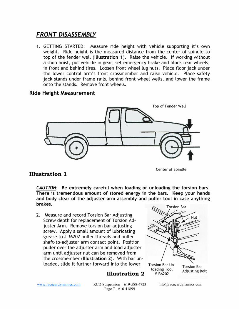
FRONT DISASSEMBLY 1. GETTING STARTED: Measure ride height with vehicle supporting it’s own
weight. Ride height is the measured distance from the center of spindle to top of the fender well (Illustration 1). Raise the vehicle. If working without a shop hoist, put vehicle in gear, set emergency brake and block rear wheels, in front and behind tires. Loosen front wheel lug nuts. Place floor jack under the lower control arm’s front crossmember and raise vehicle. Place safety jack stands under frame rails, behind front wheel wells, and lower the frame onto the stands. Remove front wheels.
CAUTION: Be extremely careful when loading or unloading the torsion bars. There is tremendous amount of stored energy in the bars. Keep your hands and body clear of the adjuster arm assembly and puller tool in case anything brakes. 2. Measure and record Torsion Bar Adjusting
Screw depth for replacement of Torsion Ad-juster Arm. Remove torsion bar adjusting screw. Apply a small amount of lubricating grease to J 36202 puller threads and puller shaft-to-adjuster arm contact point. Position puller over the adjuster arm and load adjuster arm until adjuster nut can be removed from the crossmember (Illustration 2). With bar un-loaded, slide it further forward into the lower
Ride Height Measurement
Illustration 1
Top of Fender Well
Center of Spindle
Torsion Bar
Nut
Torsion Bar Un-loading Tool
#J36202
Torsion Bar Adjusting Bolt
Illustration 2

www.racecardynamics.com RCD Suspension 619-588-4723 [email protected]
Page 8 - #16-41899
control arm. If bar seems lodged, use a hammer to punch through hole in the back of crossmember. When bar shifts forward, the adjuster arm will fall.
3. Remove torsion bar crossmember by re-
moving the two bolts that connect cross-member to frame. With crossmember out of the way, the torsion bars can be dislodged from lower control arms and removed. Mark or separate the bars, since they must be reinstalled on the same side they were removed from.
4. Remove front shock absorbers. Detach existing front Bumpstops from upper
mounting cup.
5. Remove anti-sway bar drop links, which connect bar body to lower control arms (Illustration 3).
2WD 41299 kit, skip ahead to step 8.
6. Locate and place an index mark, for installation reference, on both the dif-ferential flange and drive axle flange.
7. Remove nut and washer from hub (Illustration 4). Remove six existing bolts
fastening drive axle to differential. Pull drive axle out of hub through lower control arm.
NOTE: Be careful not to damage the drive axle boots.
Vehicle Frame Bolt
Sway Bar Extension
Nut Lower Control Arm
Sway Bar
Illustration 3
Front Differential
Drive Axle
Existing Bolt Front Spindle & Hub Assembly
Washer
Nut
Illustration 4

www.racecardynamics.com RCD Suspension 619-588-4723 [email protected]
Page 9 - #16-41899
8. Locate two hex bolts attaching
brake caliper mounting bracket to backside of spindle. Remove caliper bracket hex bolts and lift caliper assembly off rotor.
CAUTION: Do not allow brake cali-per to hang by the brake hose.
9. Remove brake rotor. Locate
tie rod end and remove the nut. Attach Universal Steering Link Puller (J 24319) and separate tie rod end from front spindle.
10. Separate ABS sensor cable at the frame near upper control arm, if applicable.
11. Locate front lower ball joint and remove nut from ball joint. Using Ball Joint
Separator Tool (J 43631) apply pressure on tool until ball joint breaks loose from lower part of the front spindle.
12. Locate front upper ball joint. Remove nut from ball joint. Using Ball Joint
Separator Tool (J 43631) apply pressure on tool until ball joint breaks loose from upper part of the front spindle.
13. Remove front spindle with the hub and bearing assembly attached, set aside.
Remove lower control arm pivot bolts and remove lower control arm (Illustration 5).
14. Repeat steps 4 thru 13 on opposite side.
2WD 41299 kit, skip ahead to Front Installation.
Vehicle Frame
Nut & Washer
Lower Control Arm
Bolt & Washer
Bolt & Washer
Illustration 5
Vehicle Frame
Upper Differential Mount
Passenger Side Dif-ferential Mount
Differential

www.racecardynamics.com RCD Suspension 619-588-4723 [email protected]
Page 10 - #16-41899
15. Remove the differential skid plate, if vehicle is so equipped.
16. Locate front drive shaft U-
joint to differential yoke. Place an index mark for instal-lation reference on both the drive shaft U-joint and differ-ential yoke. Remove hard-ware from the yoke and slide shaft rearward to disengage. Tape bearing cap assemblies and secure shaft out of the way.
17. Disconnect the electrical connector and vent hose from differential assembly.
18.Check Differential fluid level. Ensure that fluid level is 1/2” below the fill
plug.
19. Support front differential assembly with a floor jack. Remove the upper mounting hardware and passenger side axle hardware (Illustration 6). Slowly remove the differential assembly from vehicle, and lower it to the floor.
20. On 4WD (Kit #41899) only, use a suitable cutting tool (not a torch) and cut
off driver side differential mount bracket approximately 1-½” to 1-5/8” (Illustration 7). If equipped, remove bolt on cross brace. Clean sharp edges and weld Frame Cap (20-830554) in place. Paint exposed metal.
21. Locate upper mount on front differential housing. Cut off upper mount
(Illustration 8). If necessary, remove material from the left side of differen-tial to provide clearance for the lower control arm frame mount, so differen-tial can be centered on vehicle.
NOTE: Use Suitable Cutting Tool & Cut Off As Shown. Do Not Use Cutting Torch.
Differential
Weld Cap In Place 20-830554
1 inch
Illustration 7
Illustration 8 During Installation Grind This Area if Necessary
Cut Upper Mount
1/4” Front Differential

www.racecardynamics.com RCD Suspension 619-588-4723 [email protected]
Page 11 - #16-41899
FRONT INSTALLATION
2WD 41299 kit, skip ahead to step 3.
1. Install Bushings (15-11148) and Sleeve (20-832725), into Differential Support Bracket (20-51899-7). Attach differential support bracket assembly to front differential (Illustration 9). Install with Loctite compound and hardware pro-vided. Torque bolts to 45 ft. lbs.
NOTE: When attaching the differential support bracket, gear oil may leak from the case. Place this assembly in a large oil pan before removing hardware to catch the excess oil. Add one excess pint of factory recommended lubricant to full differential while out of vehicle by tipping on side. (Axle lubricant GM P/N1052271 or SAWE 80W-90 GL-5 Gear Lubricant.
2. Loosely attach the passenger side Differential Drop Bracket (20-51899-8) to
the differential axle. Use hardware provided (Illustration 10).
3. Install Front Crossmembers (20-51899-1) into existing front lower control
arm mounting pockets using existing hardware (Illustration 11). Make sure
Hex Bolt, 10mm x 60mm
Flat Washer, 10mm
Bushing, 15-11148
Sleeve, 20-832725 Differential Support Bracket, 20-51899-7
Front Differential
Illustration 9 Bushing, 15-11148 Flat Washer, 7/16”
Hex Bolt, 7/16” x 3” lg.

www.racecardynamics.com RCD Suspension 619-588-4723 [email protected]
Page 12 - #16-41899
bolt heads are facing to the front of vehicle. Do not fasten at this time. 4. Refer to Illustration 11 and install Rear Crossmember (20-51899-2) into exist-
ing rear lower control arm mounting pockets with existing hardware. Make sure bolts heads are facing to the front of vehicle. Do not fasten at this time.
5. Attach existing Bumpstops to rear crossmember Bumpstop pad using hardware
previously removed.
Vehicle Frame, Passenger Side
Differential Drop Bracket, 20-51899-8
NOTE: Large Hole in bracket faces front of
vehicle
Passenger Side Differential
Top Lock Nut, 9/16”
Flat Washer, 9/16”
Existing
Bolt, 9/16” x 1-3/4”
Flat, Washer, 9/16”
Illustration 10
Note: Install existing hardware with bolt heads facing front of vehicle.
Existing
Front Crossmember 20-51899-1
Rear Crossmember 20-51899-2
Existing
Illustration 11

www.racecardynamics.com RCD Suspension 619-588-4723 [email protected]
Page 13 - #16-41899
2WD 41299 kit, skip ahead to step 10.
6. Support front differential assembly with a floor jack. Slowly raise differential assembly into position.
7. Place front driver side Differential Support Bracket between tabs located on
front crossmember. Position the rear driver side differential mount to rear crossmember differential mounting area. Install passenger side Differential Drop to frame bracket, using existing hardware. Use existing hardware to at-tach Differential Support Bracket to front crossmember. Attach rear differen-tial mount to rear crossmember using the Locating Spacer (20-830866) be-tween mount and differential to help center differential. Do not tighten at this time.
NOTE: Check to make sure the differential is centered in vehicle. On both sides of vehicle measure the distance from the flat surface of drive axle to center of the lower bolt head attaching lower control arm to rear crossmember. Make sure distance is the same on both sides before fastening. 8. Reconnect differential vent hose and electrical connector.
9. Align marks previously made on front drive shaft U-joint and differential yoke.
Reconnect front drive shaft to the differential. 10. Install lower control arms into Front and Rear Crossmembers using 5/8” hard-
ware provided. Do not tighten at this time.
11. Torque existing lower control arm to crossmember nuts to 121 ft. lbs.. Start-ing with front then the rear. Torque front differential mounting hardware to 75 ft. lbs.
12. Remove the existing O-ring, splash shield, ABS wires, hub and bearing assem-
bly from front spindle. Reinstall the O-ring, splash shield and hub and bearing assembly to new Front Spindle (20-51800-5D Drvr.) and (20-51800-6P Pass).
NOTE: Make sure hub and bearing assemblies are reinstalled on the same side they were removed from. Apply Loctite compound to existing hardware. Torque bolts to 133 ft. lbs. 13. Connect driver side front spindle assembly to the upper and lower control arm
ball joints. Torque upper ball joint nut to 37 ft. lbs. Torque lower ball joint nut to 74 ft. lbs.
14. Loosen tie rod end jam nut and thread tie rod inward two complete turns.
Retighten jam nut and attach tie rod to front spindle. Torque nut to 37 ft. lbs.

www.racecardynamics.com RCD Suspension 619-588-4723 [email protected]
Page 14 - #16-41899
WARNING: Vehicles manufactured before 8/01/00 will need tie rod end replace-ments. See Notes in front of instructions.
2WD 41299 kit, skip ahead to step 17. 15. Install the drive axle into the front spindle, using hardware previously re-
moved. NOTE: Do not lubricate the drive axle splines and front spindle with grease. 16. Place Drive Axle Spacer (20-51899-20), against differential flange (Illustration
12). Align reference marks on axle flange and differential flange, making sure all mounting holes are aligned with each other. Attach with hardware provid-ed using Loctite compound provided. Torque bolts to 59 ft. lbs. Rotate axle assembly to ensure spacer bolt heads clear frame. Clearance frame if neces-sary.
17. Install brake rotor. Attach front caliper and bracket assembly with previously removed hex bolts. Torque caliper mounting bracket bolts to 129 ft. lbs.
18. Torque Axle hub nut to 165 ft. lbs.
19. Install new longer front Shock Absorbers
(BE5-6135). You need at least ½” clear-ance between Shock body and stock bumpstop frame bracket. If not, grind leading edge of stock bumpstop bracket as shown in Illustration 13.
Front Differential Drive Axle Spacer, 20-51899-20
Drive Axle
Illustration 12 Hex Bolt, 10mm x 50mm
Flat Washer, 10mm
Illustration 13 Driver’s Side Shown

www.racecardynamics.com RCD Suspension 619-588-4723 [email protected]
Page 15 - #16-41899
20.Repeat steps 12 through 19 on opposite side.
21. Re-install front skid plate if equipped using existing hardware previously re-moved. Use Spacer (11-15144) and 3/8” hardware provided and attach to Rear Crossmember.
22. Cycle front suspension through full travel cycle and check for adequate clear-
ance between shocks, Bumpstops, and brake line hoses.
23. Remove the trans skid plate, if vehicle is so equipped.
24. Install Bushings (15-11148) and Sleeves (20-830918) into both ends of Lateral Compression Struts (20-51899-9). Attach Lateral Compression Strut to the strut mount bracket located on Rear Crossmember using hardware provided (Illustration 14). Do not tighten at this time.
25. Attach Strut Mount Bracket (20-51099-22) to opposite end of Compression
Strut. Rotate Compression Strut upward until bracket contacts bottom of the transmission crossmember. Use Bracket as a guide to mark the mounting hole locations. Drill ½” hole through crossmember at each of the marked loca-tions. It may be necessary to drill through both top and bottom of transmis-sion crossmember. Install using ½” hardware provided. Torque nuts to 65 ft. lbs.
26. If vehicle is equipped with a trans skid plate, notch the skid plate for clear-
1/2” Nut & Washer
Transmission Crossmember
Sleeve, 20-832868
Lateral Compression Strut, 20-51899-9
Front Rear Crossmember
1/2” Nut & Washer
Bushing, 15-11148
Sleeve, 20-830918
Bolt, 1/2” x 4”
Bolt, 1/2” x 3”
Strut Mount, 20-51099-22 Illustration 14

www.racecardynamics.com RCD Suspension 619-588-4723 [email protected]
Page 16 - #16-41899
ance of the strut mount bracket. Reinstall skid plate using existing hardware.
27. Position Torsion Bar Drop Brackets (20-51899-3) against the frame rail cen-tered directly below the old torsion bar crossmember bracket. Using the bracket as a guide, mark and center punch mounting hole locations (Illustration 15).
CAUTION: Check backside of frame rail before drilling. Move any components (gas lines, brake lines, etc.) that might get damaged. Drill 7/16” diameter hole at each of the marked locations. 28. Load torsion bars into their
respective lower control arms. Slide torsion bars for-ward.
29. Install Bushing (15-11174)
and Sleeves (20-832257) into Torsion Bar Drop Brackets. Attach Torsion Bar Drop Brackets to torsion bar cross-member using the existing hardware previously re-moved.
30. Install the torsion bar cross-
member assembly into previously drilled holes. Tighten using 7/16” hardware provided and torque nuts to 60 ft. lbs.
31. Slide torsion bar rearward through the torsion bar crossmember while holding
adjustment arm in the proper position. Verify that reference marks on adjust-ment arm and torsion bar matches.
32. Install the Torsion Bar Unloading Tool (J 36202). Be very careful while in-
creasing tension on the torsion bar.
33. Reinstall retainer plate and adjusting bolt. Thread adjusting bolt until ex-posed length matches the measured length before removal. This way, they can be installed in the stock position.
34. Repeat steps 30 through 32 on opposite sides.
35. Measure the diameter of the hole in the Passenger and Driver lower control arms for the sway bar extension bolt. If it is less than 5/8” then it will need to be reamed to 5/8” in order to provide proper clearance for the sway bar
extension. Chamfer the edges of the reamed hole so that no sharp edges
7/16” Washer & Top Lock Nut
Torsion Drop Bracket 20-51899-3
Sleeve, 20-832257
Torsion Bar Crossmember Existing
Bushing, 15-11174
Frame
7/16” Washer
Bolt, 7/16” x 1-1/4”
Illustration 15

www.racecardynamics.com RCD Suspension 619-588-4723 [email protected]
Page 17 - #16-41899
contact the bolt or bushings.
36. Install front tire/wheel assemblies and lower vehicle to the ground. Torque lug nuts.
37. When vehicle is at ride height,
torque lower control arm to front and rear crossmember’s pivot nuts to 121 ft. lbs.
38. Reinstall existing sway bar to lower
control arm using Sway Bar Exten-sion (20-833739) and tighten hard-ware provided (Illustration 16).
REAR INSTALLATION
1. Raise the vehicle. If working without a shop hoist, support vehicle with suita-ble safety stands. To do this, put vehicle in gear, block front wheels, both in front and behind tires, then disengage emergency brake. Place floor jack un-derneath rear axle and raise vehicle. Place suitable safety stands under frame to support vehicle and lower vehicle onto safety stands. Remove rear tire/wheel assemblies.
2. With the floor jack, raise the rear axle enough to relieve tension on the shock
absorbers and remove shocks.
3. On driver’s side, remove rear U-bolts attaching rear axle to leaf spring. Care-fully lower rear axle enough to insert riser block.
4. CAUTION: Do not allow axle to hang by any hoses or cables.
5. Insert new riser Block (20-830658) on axle pad. Make sure the pin in block in-
dexes into hole of the axle housing spring pad. The short end of block faces toward the front of vehicle. Carefully raise rear axle until block makes con-tact with leaf spring. Make sure center bolt is aligned with hole in block (Illustration 17).
Illustration 16 1/2” Nyloc Nut
13-10878-Z
Bushing, Flex Joint 15-11746
Flex Joint Sway Bar Link
(20-833739)=9-1/2”
Bushing, Inner 15-11616
Bushing, Outer
15-11629
Bolt, 1/2” x 3” 13-22743-Z
Washer 13-30694-Z
Sway Bar
Lower Control Arm
Washer 13-30694-Z

www.racecardynamics.com RCD Suspension 619-588-4723 [email protected]
Page 18 - #16-41899
6. Remount axle to spring
using new U-bolts, wash-ers and nuts and existing spring plates. Torque U-bolt nuts to 85-100 ft. lbs.
7. Repeat steps 3 through
6 on passenger side.
8. Remove existing rear bumpstop from bottom of frame rail.
9. Install rear Bumpstop Ex-tension (20-51292-15) to frame rail at the original bumpstop location using existing hardware. Grind k n o b o f f r u b b e r Bumpstop before in-stalling existing bumpstop to Extension. Use 3/8” hardware provided and torque Nuts to 30 ft. lbs.
10.Repeat steps 8 and 9 on opposite side.
11. Install and tighten new Shock Absorbers (BE5-6134) using existing hardware to
attach shock to lower axle mount. Torque nuts to 52 ft.lbs. Attach shock to upper frame mount & torque to 13 ft.lbs.
12. If needed, install Rear Brakeline Extension (20-51292-14).
13. Install rear tire/wheel assemblies and lower vehicle. Torque lug nuts.
14. Check all fasteners are secured on both front and rear of vehicle. Turn steer-
ing to full left, then full right, and check for proper clearance.
Leaf Spring
U-Bolt, 13-90347
Rear Block, 20-830658
5/8” High Nuts & Washers
Illustration 17

www.racecardynamics.com RCD Suspension 619-588-4723 [email protected]
Page 19 - #16-41899
SOME FINAL NOTES
After installation is complete, double check that all nuts and bolts are tight. Refer to the torque specifications on last page.
If new tires were installed that are more than 10% taller than original tires,
the speedometer must be recalibrated for the Rear Wheel Anti-Lock Brake System to function properly. Contact an Authorized GM dealer for details on recalibration.
With vehicle on the floor, cycle steering lock to lock and inspect steering, sus-
pension and driveline systems for proper operation, tightness and adequate clearance. Recheck brake/hose fitting for leaks. Be sure all hoses are long enough.
Have headlights readjusted to proper setting.
Have front end aligned to factory specifications. Be sure vehicle is at desired ride height prior to realignment.
TORQUE SPECIFICATIONS (Grade 8 & Class 10.9)
5/16” NUTS 20ft. lbs. M6 9 ft. lbs. 3/8” NUTS 35 ft. lbs. M8 23 ft. lbs. 7/16” NUTS 60 ft. lbs. M10 45 ft. lbs. 1/2" NUTS 90 ft. lbs. M12 75 ft. lbs. 9/16” NUTS 160 ft. lbs. M14 120 ft. lbs. 5/8” NUTS 175 ft. lbs. M16 165 ft. lbs.
EXISTING HARDWARE TORQUE SPECIFICATIONS DIFFERENTIAL SUPPORT BOLT 10mm 45 FT. LBS. TORSION BAR CROSSMEMBER NUT 46 FT. LBS. DRIVE AXLE BOLT 58 FT. LBS. UPPER BALL JOINT NUT 37 FT. LBS. LOWER BALL JOINT NUT 74 FT. LBS. LOWER CONTROL ARM NUT 101 FT. LBS. HUB & BEARING ASSEMBLY BOLT 133 FT. LBS. FRONT AXLE SHAFT NUT 165 FT. LBS. BRAKE CALIPER TO F. KNUCKLE BOLT 129 FT. LBS.