a 10gbps ethernet tcp/ip processor - hot chips 10gbps ethernet tcp/ip processor hot chips 15 -...
TRANSCRIPT
A 10Gbps Ethernet A 10Gbps Ethernet TCP/IP ProcessorTCP/IP Processor
HOT Chips 15 - August 17, 2003
Jianping Xu, Nitin Borkar, Vasantha Erraguntla, Yatin Hoskote, Tanay Karnik,
Sriram Vangal, Justin Rattner
Microprocessor Research, Intel Labs

2
Outline
TCP/IP processing challengesTCP/IP protocol processor (TIPP) features TIPP microarchitectureTIPP implementationExperimental chip performanceSummary
3
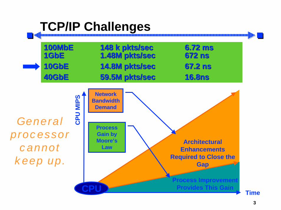
TCP/IP Challenges100MbE100MbE 148 k 148 k pktspkts/sec/sec 6.72 ms6.72 ms1GbE1GbE 1.48M 1.48M pktspkts/sec/sec 672 ns672 ns10GbE10GbE 14.8M 14.8M pktspkts/sec/sec 67.2 ns67.2 ns40GbE40GbE 59.5M 59.5M pktspkts/sec/sec 16.8ns16.8ns
General processor
cannot keep up.
ArchitecturalEnhancements
Required to Close the Gap
Process ImprovementProvides This Gain
Time
Process Gain byMoore’s
Law
NetworkBandwidth
Demand
CPU
CPU
MIP
S

4
CPU Requirements
0
2
4
6
8
64B 1KB 2KB 16KB 64KB
Transfer Size
GH
z/G
bps
TXRX
0.0%
20.0%
40.0%
60.0%
80.0%
100.0%
64B 1KB 2KB 16KB 64KB
Transfer size
% C
PU u
tiliz
atio
n
0
200
400
600
800
1000
Mbp
s
CPU Utilization-TX CPU Utilization-RXThroughput-TX Throughput-RX
Throughput & CPU Utilization (2.4GHz)

5
Ingress Processing
Packet Filter
ProtocolDemuxer
IPReassembler Execution Unit
(UDP Proc)
TCP IngressProcess Engine
BootPROM
Ingress Processing
Ingress Stream
Internal Bus
PHY
RxBuf
TxBuf
SPII/F
Ingress Proc
Egress Proc
MAC
PCIexpress
XBarSDRAM I/F
Host
6
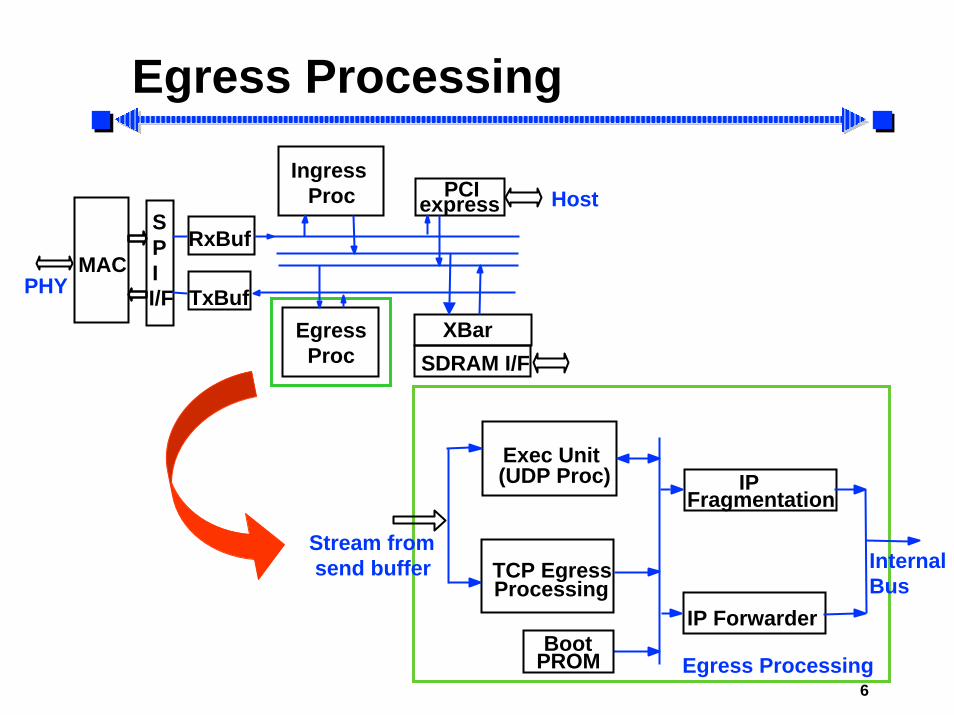
Egress Processing
IP Forwarder
IPFragmentation
Exec Unit(UDP Proc)
TCP EgressProcessing
BootPROM Egress Processing
Stream fromsend buffer Internal
Bus
PHY
RxBuf
TxBuf
SPII/F
Ingress Proc
Egress Proc
MAC
PCIexpress
XBarSDRAM I/F
Host

7
TCP Offload
0
20
40
60
80
100
Pro
toco
l typ
e (%
)
TCP Others
Why TCP processing?• 82% of all traffic is TCP• TCP processing is the bottleneck
— complex— compute intensive
UDP
Packet Filter
ProtocolDemuxer
IPReassembler Exec Unit(UDP Proc)
TCP IngressProc Engine
BootPROM
Ingress Processing
Ingress Stream
Internal Bus

8
Key Features of TIPPSpecial purpose processor– Dual frequency, low latency, buffer-free design– High frequency execution core– Accelerated context lookup and loading
Programmability for up-to-date protocols– Programmable design with special instructions– Rapid validation and debug
Scalable solution– Across bandwidth and packet sizes– Extendable to multi-core solution

9
TIPP Organization
CAM — Content Addressable Memories IDB — Ingress Dispatcher BlockTCB — Transmission Control Block SR — State Register ECore — Execution Core SP — Scratch Pad IROM — Instruction ROM EB — Egress Buffer
CAM1
CAM2ECore
IDB
IROM
SP
TCB
SR
EB
6
32 118
32
96
264
32
32
32
112
10GbEingressstream
egressstream
HighFrequency
10
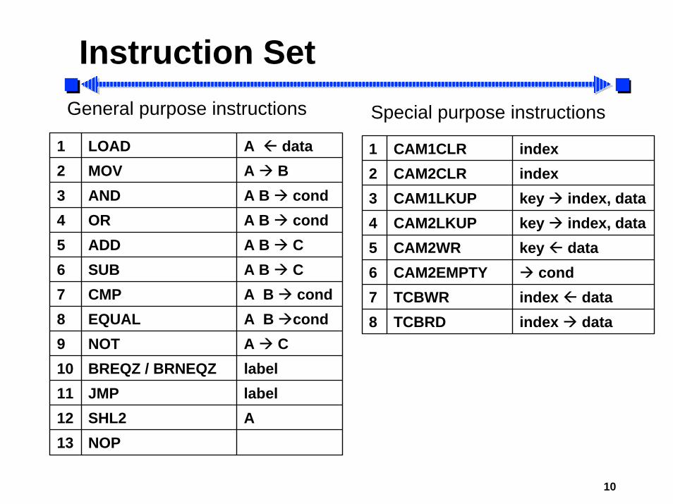
Instruction SetGeneral purpose instructions Special purpose instructions
1 LOAD A data2 MOV A B3 AND A B cond4 OR A B cond5 ADD A B C6 SUB A B C7 CMP A B cond8 EQUAL A B cond9 NOT A C10 BREQZ / BRNEQZ label11 JMP label12 SHL2 A13 NOP
1 CAM1CLR index2 CAM2CLR index3 CAM1LKUP key index, data4 CAM2LKUP key index, data5 CAM2WR key data6 CAM2EMPTY cond7 TCBWR index data8 TCBRD index data

11
High Speed Execution Core
IDB SR
index
TCBTCB
264
Key CAM1
6
ALUCAM2
Ingressstream
SP PCPipelinedALU
Branch addressStart address
IROM
9
3232
112
IR
decode
ALU output
Next address
pipestage
96

12
ALU
ALU Out
pipelinedadd / sub
pipelinedcmp / equal
orand not shl2 loadmov
Source A Source B32 32
Cond regIROM Pipe stage
13
Packets Reordering
Packets arrive in random orderConventional software solution uses sorting to reorder packetsHardware sorting is expensive and cumbersomeUse CAM to eliminate sorting– Store and lookup of packets in CAMs by
sequence number – Combine adjacent packets in CAMs
Critical for wire speed processing

14
System Scalability
Multi-core solution with each core supporting up to 8K connectionsLarge number of connections: > 32K to 64K
4 signal handshake between CTL and each TIPP
TIPP offload engine
CTL
CTL
15
Enabling Circuit Technologies
Quaternary tree adder architecture Dual-VT design Semi-dynamic flip-flopsHigh speed instruction ROM High bandwidth, leakage tolerant register fileAdaptive body biasMultiple clock domain synchronization

16
Experimental Chip
ExecCore
PLLTC
B ECore
PLL
CAM2
IROM
CA
M1
IDB
EB
2.23 x 3.54mm2
-VT
1 poly, 7 metal460K306
Chip AreaProcess
InterconnectTransistorsPad count
2.23 x 3.54mm2
90nm comm.CMOS
1 poly, 7 metal460K306
Chip AreaProcess
InterconnectTransistorsPad count
17
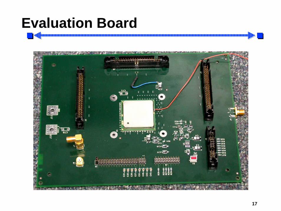
Evaluation Board
Fully functional silicon

18
Measured Processing Performance
0
2
4
6
8
10
0.8 1 1.2 1.4 1.6 1.8
Vcc (V)
Pro
cess
ing
Rat
e (G
bps)
4.4Gbps, 0.9V
9.64Gbps, 1.72V
19
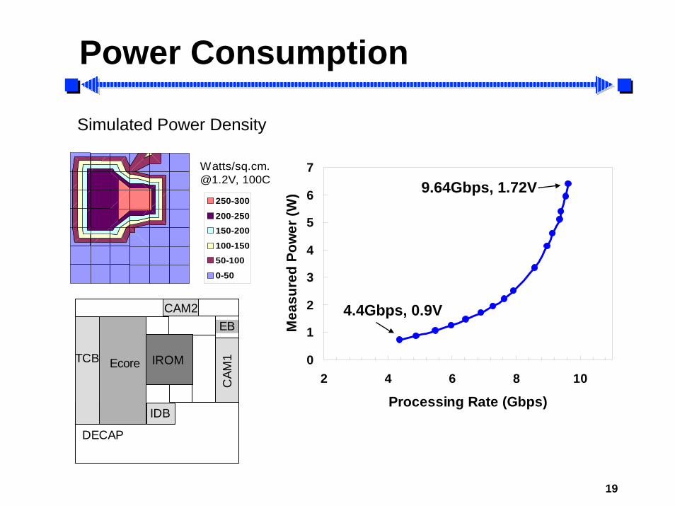
Power Consumption
Simulated Power Density
0
1
2
3
4
5
6
7
2 4 6 8 10
Processing Rate (Gbps)
Mea
sure
d Po
wer
(W)250-300
200-250150-200
100-15050-100
0-50
Watts/[email protected], 100C 9.64Gbps, 1.72V
4.4Gbps, 0.9V
DECAP
EB
Ecore IROMTCB
CAM
1
IDB
CAM2

20
Summary
Programmable hardware engine– Line-speed TCP ingress processing– Support minimum packet size
Dual frequency and buffer-free design – High speed execution core– 9.64Gbps processing at 1.72V, 6.39W in 90nm
communication CMOS process– Extendable to large number of connections
Dynamic reordering of packets in hardware

21
Acknowledgments
B. Bloechel, G. Dermer, D. Finan, J. Howard, K. Ikeda, D. Klowden, S. Narendra, H. Nguyen, C. Parsons, G. Ruhl, D. Somasekhar, S. Tang, K. Truong, J. Tschanz, V. Veeramachaneni, H. Wilson for the TIPP experimental chip contributions A. Foong, F. Hady for simulation contributionsS. Borkar, M. Haycock for encouragement and support