a brief review of technology and materials for aerostat
TRANSCRIPT

OPEN ACCESS Asian Journal of Textile
ISSN 1819-3358DOI: 10.3923/ajt.2018.1.12
Review ArticleA Brief Review of Technology and Materials for AerostatApplication
Bharathi Dasaradhan, Biswa Ranjan Das, Mukesh Kumar Sinha, Kamal Kumar, Brij Kishore andNamburi Eswara Prasad
Defence Materials and Stores Research and Development Establishment (DMSRDE), G.T. Road, 208013 Kanpur, Uttar Pradesh, India
AbstractThis review article presented a brief introduction and features of the Aerostat and the inflatable textile and polymeric materials used fordeveloping envelope structure. Aerostat is basically an inflatable balloon fly at certain height and carries necessary items for collectingthe ground information and transmitting the same to the defence source unit. The envelope used to fill with light air in pressurizedcondition to provide the desire lift. This review article also summarized various classes of aerostats, different components of aerostat,property requirements, fabrication methods and evaluation methods for the envelope structure. The functional features of variousmaterials used for different components of aerostat meeting the very stringent requirements are briefly discussed. The aerostat wassubjected to open environmental condition, hence the material selection for developing such structure with better durability was thematter of worry for the researchers for last few decades and some developments in this segment is evolved and brought out very broadlyin this article. The fabrication methods for assembling together different layers of laminate structure and joining techniques for differentparts of aerostat were also discussed. The different components of aerostat were developed with laminated fabrics of different aerialdensities but with similar functions. This article also explained the different layers of the laminated fabrics with their material and functional features. The recent developments occurring worldwide and the status in Defence Research and Development Organization(DRDO) for developing envelope structure were explored.
Key words: Aerostat, polyester, laminated fabric, hull, fin, payload, helium, ultraviolet
Citation: Bharathi Dasaradhan, Biswa Ranjan Das, Mukesh Kumar Sinha, Kamal Kumar, Brij Kishore and Namburi Eswara Prasad, 2018. A brief review oftechnology and materials for aerostat application. Asian J. Textile, 8: 1-12.
Corresponding Author: Biswa Ranjan Das, Textile Division, Defence Materials and Stores Research and Development Establishment, G.T. Road,208013 Kanpur, Uttar Pradesh, India Tel: +91-9506741256 Fax: +91-0512-2450404
Copyright: © 2018 Bharathi Dasaradhan et al. This is an open access article distributed under the terms of the creative commons attribution License, whichpermits unrestricted use, distribution and reproduction in any medium, provided the original author and source are credited.
Competing Interest: The authors have declared that no competing interest exists.
Data Availability: All relevant data are within the paper and its supporting information files.

Asian J. Textile, 8 (1): 1-12, 2018
Density of air = 1.275 kg mG3
Density of helium = 0.1664 kg mG3
Buoyant force = 1.275 kg x 9.8 m secG2
= 12.5 N
Gravitational force= 0.1664 kg x 9.8 m secG2
= 1.63 N
Helium
INTRODUCTION
Aerostat is an aerodynamically shaped non-rigid/flexiblestructure. The aerostats may be tethered or un-tethered. Thelighter than air (LTA) helium gas is used to create the upwardpositive lift of the aerostat structures1,2. The Archimedes’principle of buoyancy involved in creating the aerostat lift3,4 is shown in the following Fig. 1.
They are actually employed at greater heights to achievecertain purposes5. In actual operation, these structures will besubjected to different mechanical stresses and harshenvironmental conditions where they are exposed to highlevel of sunlight, temperature, water and moisture6. Thedeveloped aerostat structure should be able to remain aloft inthese extreme conditions while maintaining its functionalityand endurance7. The wide range of applications is constantly
increasing the weight of payload on the aerostat platform.So the envelope material with high-strength to weight ratioshould be achieved so as to maximize the payload capacityand also to bear the envelope stress. The aerostat structurebasically comprises three distinct segments, hull, fin andballonet. A representative image of the aerostat is shown inthe Fig. 2. Hull is the main balloon containing helium gas. Hullshape is the critical factor which determines the net stressacting on the structure which in-turn affects the payloadcarrying capacity and efficacy of the system8. Adequately sizedfins are attached to the hull body for stabilizing the structureduring wind disturbances5,8,9. Fins are also formed of highstrength material laminated with flexible films. Aerostatsemployed at an altitude of 15,000 feet are subject to extremechange in atmospheric temperature and pressure. In thesehigh altitudes, Ballonet which is an air-filled compartment
Fig. 1: Schematic diagram of Archimedes’ principle involved in aerostat lift
Fig. 2: Representative image of aerostat system
2
Hull
Fin
Ballonet

Asian J. Textile, 8 (1): 1-12, 2018
is used within the hull structure to maintain aerodynamicshape of the aerostat by controlling its internal pressure. Thisis achieved by varying the ballonet volume with the use ofblowers and valves5,10. A differential pressure sensor sensesthe internal envelope pressure. According to the sensedpressure, the valves or blower are activated to control thepressure change of the helium gas beyond a certain value,thus maintain the shape of the aerostat envelope11,12.
Aerostats has been used for a number of civilian as well asmilitary applications, surveillance, security and control, tacticalcommunication relay, personnel location and tracking,broadcasting of an event, advertising and police patrolling incities1,3,6,7. The limited on-station time and the operational costlimit the use of multiple aircrafts for these applications3,6,13.
AEROSTAT CLASSES
Based on the load carrying capacity, deployment heightand the volume, the aerostat can be grouped into three mainclasses.
Tactical aerostat systems: These aerostats are designed to lifta payload of around 60 lbs to an altitude of around 1000 feet.The balloon volume is around 6000 cubic feet. The flightduration with adequate free lift can be achieved for around5-7 days, after which some helium addition should be done tomaintain the lift of the balloon. In airborne state they canwithstand 40 knot wind speed and in moored condition theycan survive 50 knot wind speed14.
Operational aerostat systems: Operational class aerostatsystems are medium-sized aerostats that are deployed ataltitudes of 3,000-5,000 feet with a payload range of300-800 lbs. The hull volume ranges from 800-1600 cubicmeters depending on the payload load weight and thedeployment height. The typical flight duration is more than7 days which can be extended up to 4 weeks upon heliumaddition to the aerostat. This class of aerostat is designed towithstand 50 knot winds in air-borne state and 70 knot windin moored state15.
Strategic aerostat systems: Strategic class of aerostat systemsincludes some of the largest tethered aerostats. They can lifta payload of around 3500-7000 lbs to an altitude of around10,000-15,000 feet above the sea level. This class of aerostathas long flight duration and remain deployed continuously foraround 30 days16.
PROPERTY REQUIREMENTS FOR AEROSTAT
For high altitude deployments, the envelope materialshould possess the following properties6,17-19:
C First and foremost, the envelope material should exhibitlow gas permeability. This minimizes the helium lossthereby increasing the deployment time
C The envelope material should be light weight to decreasethe overall weight of the structure. This aids inmaximizing the payload capacity
C Sufficient strength is necessary to withstand differentstresses acting on the hull structure
C High tear resistance is important to maximize the damagetolerance. High tear strength is required because evensmall tears that are induced during handling or installingcan lead to catastrophic failure of the entire system
C These materials that are employed at high altitude shouldwithstand wide temperature and pressure variationswithout any changes in their physical and strengthproperties. The material should retain its flexibility overwide range of temperature variation
C It should also be resistant to environmental degradationfactors such as Ultraviolet (UV), ozone, humidity, heavywinds and extreme weather conditions. This improves theself-life of the structure
C The structure should also show excellent creep resistanceto maintain the balloon shape throughout its entire life
C The fabric will be subject to bending forces duringinflation and deflation process and also in aloft condition.So the structure should be resistant to flex-fatigue
C To prevent delamination, the layers of the structureshould have good adhesion with the adjacent layers.Good joint performance is necessary to maintain theintegrity of the structure
The design of the aerostat structure should meet all theabove mentioned properties for long-term use in allenvironmental conditions. This cannot be achieved with asingle layer structure, so a multi-layer laminate structure isdesirable6. The fabrication methods must produce a consistentstructure over time with minimum variation of its performanceproperties. This can be easily achieved when fabrication isdone in accordance with some specified standards20.
HULL MATERIAL CONSTRUCTION
To meet all the desirable properties there is a needfor the envelope of the aerostat to be made of multi-layer
3

Asian J. Textile, 8 (1): 1-12, 2018
Fig. 3: Multi-layer structure of typical hull material
Table 1: Comparison of high performance fibresMaterials Strength (g/den)10,19 Advantages DrawbacksM5 (PIPD) >40 Very high strength to weight ratio, good compressive Expensive, not commercially available10
properties, excellent environmental resistanceZylon (PBO) 42 Excellent modulus, high specific strength6,19 Poor abrasion and flexing resistance, poor UV, visible
light and moisture resistance, expensive10,19
Spectra (PE) 25-40 Light weight, high toughness19, flexible Poor creep resistance, highly hydrophobic and good weather-ability10 reducing its bond-ability with resin and low melting
point19
Thornel (Cabon) 30 High modulus, good temperature resistance, Stiff and brittleexcellent weather-ability
Vectran (LCP) 23 High strength to weight ratio, excellent tear resistance, Not as strong as Spectra or Zylonexcellent resistance to creep and fatigue10,18
E-glass 23 High modulus19 High stiffness, damages on folding19
Polyester HT 12 Good UV resistance6 Poor elastic recovery properties6
Kevlar (Aramid) 22 Good strength to weight ratio, high thermal resistance6 Susceptible to photo-degradation, poor flex andabrasion resistance, poor stress distribution whichmay lead to catastrophic failure6,19
Nylon 10 Excellent flex resistance, Good elastic recovery6 Low modulus, inferior hydrolytic degradationproperties6,19
PIPD: Polyhydroquinone-diimidazopyridine, PBO: Polybenzoxazole, PE: Polyethylene, LCP: Liquid crystal polymer
flexible laminate material17,21. Typical construction ofhull material is shown in the Fig. 317.This multi-layer laminate represents a structure composed
of an interior load-bearing layer, a gas barrier layer and anexterior environmental protection layer. These layers arebonded with its adjacent layers either chemically ormechanically or by use of some polymeric materials likepolyurethanes (PU) while retaining all the desirable propertiesof the laminate structure17. Ideally, all the layers of thelaminate structure should show same degree of deformationunder stress and behave as single structure to achieve betterperformance of the structure22.
MATERIALS OVERVIEW
Load-bearing layer: The load-bearing or strength layer isusually composed of single or multiple layer(s) of wovenfabric10. When multiple fabric layers are used they are usuallybiased at some angle relative to each other. This biasing
provides good dimensional stability but ply separation anddecreased strength to weight ratio adds problem to thestructure.Cotton fabrics were used in conventional aerostat
system. Technological advancements slowly replaced thoseconventional materials with newly developed materials. Theadvancements in the properties of the synthetic fibres orpolymers made them suitable choice to be used in thestrength layer. The synthetic fibres have high strength-to-weight ratio which is one of the most desirable propertiesfor the aerostat application10. Commercially available high- modulus synthetic fibres include polyesters, polyamides,aramids, liquid crystal polymers, polybenzoxazole andultra-high molecular weight polyethylene21. High performancefibres like M5, Vectran, Zylon, Dyneema and Spectra may alsobe employed10,21. The performance properties of various highperformance fibers have been compared in Table 1.Researchers have carried out several experiments to study
the compatibility of high performance fibers in the aerostat
4
Adhesive layer
Strength layer
Adhesive layer
Gas barrier layer
Adhesive layer
Environmental protection layer

Asian J. Textile, 8 (1): 1-12, 2018
structure. They found that Vectran fits all the propertyrequirements of the fiber to be used in the load bearing layerof the multi-layer laminate. They show excellent resistance toabrasion and flex-fatigue. They have better overall propertiescompared to other high performance fibres and can be usedwithout any property change over longer period of time19. Thesuperior properties of Vectran fibre which makes it the bestchoice for the aerostat application are summarized below:
C High strength to weight ratioC Excellent tear resistanceC Excellent creep resistanceC Good abrasion resistanceC Excellent flex-fatigue resistanceC Good thermal managementC Minimal moisture absorptionC Excellent chemical resistanceC Consistent properties over wide range of temperatureC High impact resistance
The selection of weave design also affects the finalproperties of the laminate structure. The advantages anddrawbacks of some of the weaves have been discussedbelow19:
C Plain weave, the most common and simplest patternprovides high strength and dimensional stable fabricsdue to their high frequency of interlacements
C The basket weave which is a derivative of the plain weaveprovides relatively less thickness and high tear strengthcompared to plain weave
C The rip-stop weave is similar to the plain weave but thebase yarns at regular intervals will be replaced withthicker yarns to prevent the tear propagation. Durney23 inhis research work studied the use of rip stop weave toprevent the propagation of local tear in large aerostatenvelope
C Tri-axial fabric is a special weave where the fabric iswoven from three sets of yarns. These fabrics showisotropic properties in all directions
C Leno weave is an open weave with excellent dimensionalstability and very high modulus and strength.
C Twill and satin weaves are rarely used due to their poordimensional stability
Gas barrier layer: The gaps in the woven fabric of thestrength layer should be sealed completely to achieve thegas barrier property. This can be done either by coating thefabric with suitable polymeric material or by laminating thin
polymeric films with the strength layer19. The polymer materialshould have good bond-ability with its adjacent layers10. Goodshear stiffness is also important to provide stability to thelaminate structure9,10.
All polymers based on their chemical constitution arecharacterized with a particular phase transition temperaturebelow which material becomes glassy and above whichthe material turns into soft rubbery state. This transitiontemperature is around -5EC for aromatic polymers and -50ECfor aliphatic polymers. So the polymer should be carefullyselected based on application temperature otherwise it maydeteriorate the properties of the laminate structure.The commonly used gas barrier material includes
neoprene, poly vinyl fluoride and poly-urethane. Polyester film(Mylar®) having high tensile modulus, good shear stiffness andexcellent gas barrier properties makes it suitable for aerostatapplications6,19,24. The polyimide (KaptonTM) film layer has beenused as gas barrier layer in their laminate construction for theLTA vehicles. It acts as an excellent gas barrier layer holdingthe inflating gas within the hull structure18. KaptonTM isprimarily used for high temperature applications. Its excellentdielectric constant helps in diffusing the enemy targetingtreats like laser light. The polyimide polymer layer degrades onexposure to UV light so it has to be over coated with an UVstable polymeric layer18.
Poly vinyl copolymers also have excellent barrierproperties but it is rarely used in aerostats due to its poorflex properties at low temperature6,10. Poly-urethane (PU) andits derivatives act as an excellent gas barrier material withall properties conforming to the requirements of LTAvehicles6,10,17. The advantages of using PU coat are summedbelow25:
C PU has high toughness and possess superior mechanicalproperties (high tensile and tear strength, high impactresistance and very good abrasion resistance)
C They have good weather-abilityC They retain their flexibility even at low temperaturesC They show good bond-ability with textile substrates
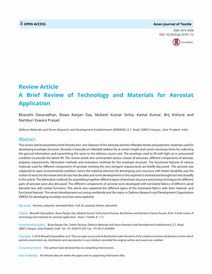
The gas barrier properties of the polymeric films can begreatly enhanced by incorporation of nano-scale fillers havinggood aspect ratio (length to thickness ratio or surface area tovolume ratio) into the polymer matrix. The incorporation ofnano-fillers produces tortuous path (Fig. 4) which suppressesthe movement of gas molecules across the gas barrier layer.Higher gas barrier properties of polymer nano-composites(PNCs) can be achieved with higher tortuosity created by thenano-fillers26-28.
5
Asian J. Textile, 8 (1): 1-12, 2018
Gas molecules Gas molecules F F F F F F F F F F
C
C
C
C
C
C
CC
C
H H H H H H H H
Polyvinylidene fluoride (PVDF)
Fig. 4: Illustration of gas transport mechanism through purepolymer and nanomaterial incorporated polymer
Also, the incorporation of nano-elements of high aspectratio into the polymer matrix produces an ultra largeinterfacial area between the incorporated nano-elements andthe base polymer matrix which leads to superior properties ofthe nano-composite compared to conventional materials27.
Nanoclay has been widely used for gas barrierapplications. However, the clay particles being hydrophilic innature agglomerate easily. This even deteriorates theintrinsic properties of the base polymer material26. This clayagglomeration can be overcome by modifying it withtransition metal ions. The resulted modified clay (Fe clay orCu clay) showed very good dispersion with significantimprovement in gas barrier property29.Joshi et al.27 discussed various methods of preparation of
clay PNCs. Exfoliation, compatibilization, Orientation andRe-aggregation are the four important factors need to becontrolled while producing the clay PNC to achieve maximumbarrier properties. She also conducted experiments by varyingthe clay content% of PU/clay based polymer coatings forinflatables. Her experimental results suggest that increasingthe clay% improved the overall properties of the coatings interms of breaking strength, tear stress and gas permeability.However increase of clay content beyond an optimum valuedeteriorates the properties due to poor dispersion andagglomeration of the clay particles27.Recently graphene and its derivatives are widely used for
gas barrier applications due to its very small atomic thickness(10 Å) and two dimensional structures. Graphene possessmany superior properties when compared with clay particles.This can be attributed to the planar hexagonal arrangementof the sp2 hybridized carbon atoms in the graphenestructure26,28. Graphene and its derivatives are usuallyfabricated by the following methods, (i) One method bydepositing ultra-thin graphene sheets on top of the polymericfilm and the other method by incorporation of graphenesheets into the polymer matrix28.
Pierleoni et al.30 studied the gas barrier properties ofpolymeric films by fabricating thin layer of electrochemically
Fig. 5: Structural formula of PVDF polymer
ex-foliated graphene oxide (EGO) sheets on top of thepolymeric film. They observed that gas transmission ratethrough the polymeric film decreased significantly with theamount of EGO deposited on the polymeric film. Thissignificant decrease is attributed to the close packing of the2D EGO sheets which suppresses both the horizontal andvertical movement of the gas molecules across the depositedEGO layer30.Cui et al. 26 in his study reviewed the production methods
of graphene and its derivatives in detailed manner. He alsodiscussed various methods of preparing graphene-PNCs andthe process parameters that are need to be understood forachieving superior gas barrier properties26.
Environmental protective layer: This is the exterior mostlayer, which provides protection against ultraviolet rays, ozoneand also protects from other hazardous environmentalconditions10. UV radiation is one of the major causes of thedegradation of the textile material. It excites some functionalgroups in the polymer chains and caused photo degradationof the material31-33. The extent of degradation also depends onthe nature of the material and also the surface properties ofthe layer10.Derivatives of fluoro carbon polymer are widely used for
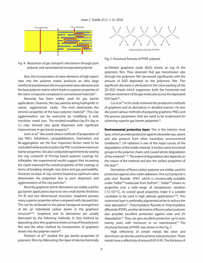
protection against ultra-violet radiations. One such polymer ispoly vinyl fluoride (PVF) which is commercially availableunder TedlarTM trademark from DuPont17. TedlarTM retains itsproperties over a wide range of temperature variation(-72-107EC). Its overall good properties make it a suitablecandidate to be used in high altitude applications10,20. Thisoutermost layer is preferably pigmented white to reduce thesolar absorption17. Polyvinylidene fluoride or Polyvinylidenedifluoride (PVDF), another derivative of fluoro carbon polymeralso provides excellent protection against solar and UVdegradation18. They can give excellent protection up to eventwenty years with minimum or no maintenance19. Thestructural formula of PVDF was shown in the Fig. 5.High reflectivity of certain metals like silver and
aluminium can also be used to achieve solar protection. Thesemetals have a reflectivity of around 0.85-0.95. The thickness of
6
Asian J. Textile, 8 (1): 1-12, 2018
Table 2: Properties comparison of different weathering materialsFlex-fatigue
Materials Permeability Heat seal-ability Weather-ability Adhesion resistance Dimensional stabilityPolyester Low No Fair Fair Fair ExcellentPolyurethane Low Yes Good Excellent Good PoorPoly-vinyl chloride Fair-low Yes Good Excellent Good PoorPoly-vinyl fluoride Low Yes (with adhesive) Excellent Poor Excellent GoodNylon Very low Yes Poor Fair Excellent ExcellentPoly-tetrafluoroethylene Fair Yes (some grades only) Excellent Poor Good GoodLow density polyethylene Fair Yes Good if pigmented Poor Excellent PoorNeoprene Low No Good Excellent --- ---
these metal layers vary from about 800 AE to about 1200 AEand these layers are applied using vacuum metallization andsputtering techniques21. This metallic coating gives moreprotection compared to non-metallic coating10. The usemetallic coating aids in dissipating the static electric charge,prevents the damage from lightning strikes and also it act asgas barrier21,34.Polyurethane and its derivatives such as polycarbonate
polyurethane can also be used for environmental protectiondue to its excellent UV stability6. Additional function ofprotection against microbes and chemicals can also beachieved by imparting certain chemicals in this layer.Pal et al.35 tried to study the degradation behavior of PU
coated nylon fabrics on exposure to outdoor environment.They observed a maximum strength loss in peak winter,suggesting that moisture plays a major role in the degradationof the material compared to sunlight. They also observed thatafter some critical time of exposure, strength decrease was inproportional to the time of exposure. Even though thestrength loss was linear with time, the hydrogen gaspermeability increased drastically on prolonged outdoorexposure beyond a critical duration of outdoor exposure. Thissuggests that gas permeability should be taken as criticalfactor in determining the life of the aerostat system35.Nuraje et al.36 studied the weathering properties of
graphene reinforced PU coatings. They showed that theaddition of graphene improved protection againstenvironmental factors like UV degradation and corrosion. ThePU coating containing graphene nanomaterial also provideshydrophobicity and improved mechanical properties of thecoating compared to mere polyurethane coating. Theseimprovements can be attributed to the unique chemicalstructure (hexagonal arrangement of sp2 carbon atoms in a2-dimensional plane) and high surface area to volume ratio ofthe graphene material36.Literature also reveals that inclusion of metal
nanoparticles like Zinc Oxide (ZnO), Cerium oxide (CeO2) andTitanium oxide (TiO2) in the polymer coatings inhibitsphoto-oxidation by absorbing the UV radiations thereby
protecting the base fabric from UV degradation37-40. Das et al.41
cited various UV absorbers that can be used in textile and theyalso discussed the mechanism of UV absorption by theparticles31,41. UV stabilizing nano-particles can also be used inconjunction with graphene or clay particles to achieve bothsun protection and gas barrier properties. Studies conductedshow that this composite mixture is advantageous in retainingefficiently both the UV protection and gas barrier propertiesafter exposure to weathering42. The properties of differentpolymeric materials used for weather protection are comparedin the Table 210,19,24.
Adhesive layer: All the layers of the structure are bondedtogether to form a single laminate using suitable adhesives.The selection of adhesives are generally based on theirbond-ability/peel strength, self-life and ease of fabricationwithout any regard to the performance properties of thelaminate structure. The adhesive may be thermoplastic orthermoset in nature. Adhesive should be thermoplastic innature when joints are formed by welding method10. Weakadhesive bonding leads to delamination of the multi-layerstructure22. So, good bond-ability even with thin layer ofadhesive is the typical requirement of the adhesive10. Certaininorganic fillers like carbon nanotubes can be added to theadhesive polymer to improve its properties21.PU is one of the commonly used adhesive for bonding
the several layers of the laminate structure. It is widely usedbecause of its flexibility even at very low temperature21.Acrylic adhesives can also be used for bonding several layersof the laminate structure6.
FABRICATION METHODS
Lamination techniques: Lamination is the process ofconverting different layers into a single laminate structure byusing an added adhesive or by using some polymeric materialwhich has adhesion properties as one of the layer of thelaminate structure. Conventionally solvent based adhesivesare used for lamination purposes. Now, environmental
7

Asian J. Textile, 8 (1): 1-12, 2018
Environmental protection layer
LTA material structure tape
considerations have replaced them with hot-melt adhesivesand thermoplastic polymeric adhesives43. Lamination can bedone in a number of ways depending on the substrate typecombinations and the number of layers44. Some of theavailable lamination techniques are briefly described below43.
Flame lamination: In this method, a pre-heated thermoplasticfilm is passed between fabric layers under pressure. Themelted polymer binds the two layers of fabric into a singlestructure. The disadvantages of this method are the highcapital cost and the harmful gases melted during heating ofthe binder film43.
Ultrasonic lamination: In this method, ultra-sonic waves withfrequencies of 20 kHz to 1 GHz are used for the lamination ofmulti-layer substrate. The amplitude of waves and the weldingforce decides the bonding strength of the material. Thismethod is considered as eco-friendly and safe process sinceno adhesive and heat application is involved in the laminationprocess44.
Adhesive lamination: The adhesive lamination can befurther classified into wet-adhesive lamination and hot-meltlamination based on the method of application and the natureof adhesives. Wet-adhesive lamination process use eitherwater-based or solvent-based adhesives. Here, the liquid(water or solvent)-based adhesives are applied on to thematerial by either roller coating or knife-over-roller coatingmethod and the adhesive coated material is combined withanother layer material and the cured in an oven. The adhesivemelts and bonds together the layers into a single laminatestructure44.In hot-melt lamination method, thermoplastic polymers
with appropriate melting point and melt-viscosity are used asadhesives. These adhesives are applied by extrusion methodor rotogravure method. Hot-melt lamination method isenvironmental friendly compared to wet-adhesive laminationmethod since no harmful emissions are involved in theprocess43,44.
Joining challenges: A number of laminate sheets are joinedin a particular fashion to form the overall aerostat balloonstructure. These joints are subject to various tensile and shearstress while loading of the entire aerostat envelope. So thefabrication of joints should be such that the joints strengthshould be more than the strength of the base fabric10,17. Thisensures the integrity of the envelope and provides aconsistently high quality aerostat envelope.
Fig. 6: Cross-sectional view of typical butt joint
Many patterns for the joining of laminate sheets arereported in the literature. Among them, the butt joint is themost preferably used joint type for aerostat construction. Theconfiguration of the butt joint is shown in the Fig. 6.In butt joint, two pieces of the laminate are laid side by
side separated by small gap in between them. The gaps aresealed by a cover tape at the exterior side and by a structuraltape at the interior side of the laminate structure. The covertape is usually formed of a single layer of polymer having goodenvironmental stability. The structural tape has a similarconstruction of the aerostat laminate material exhibiting thesame strength and gas permeability characteristics as that ofthe base material18. In PU coated fabrics, this method ofjoining produced joints that are stronger than the basematerial19. The construction of the seam cover tape used toseal and protect the joints of the hull is reported in a UnitedStates patent34.
Joining techniques: As already stated, the method of joiningshould maintain the integrity of the aerostat structure. Tomaintain this structural integrity, the joints formed shouldefficiently transfer loads from one section to other section ofthe hull material without any rupture or damage at the jointportion of the hull. A reliable joint should absorb high stressenergy and possess high fracture toughness even at extremeoperating weather conditions10.The joining is usually done by three different principles:
C Welding technology C Bonding technologyC Mechanical stitching6,10,45
Welding technology: In this method, sealing is achieved withapplication of thermal energy. Heat intensity, material speedand pressure are the three critical parameters that are to becontrolled to achieve a properly formed seam. This method isfor sealing only thermoplastic materials. Based on the sourceof the thermal energy, this method can be further classifiedinto many sub-classes:
C Material under pressure is subject to high frequencyultrasonic vibrations. These vibrations create thenecessary thermal energy for the sealing of joints
8

Asian J. Textile, 8 (1): 1-12, 2018
C The radio-frequency welding is another welding methodwhere the fabric is clamped under pressure between theelectrodes of radio frequency while the fabric is beingwelded. Radio frequency waves being electro-magneticin nature, this method can be applied only to dielectricthermoplastic materials
C Impulse welding is based on the principle of the Joule’sheating effect. The electric current passed through a highresistance plate produces heat energy which is used forthe bonding of materials
C In hot-air welding, hot air is used as the source of thermalenergy for the bonding of materials
C In hot-wedge welding, fabrics are exposed to heatdelivered by a small wedge shaped metal piece. Theheated fabrics are then passed through a pair of rollers forthe sealing of the fabrics
Bonding technology: In this method, bonding is achieved byapplication of structural adhesives between the two layers ofmaterials which are to be bonded. This is done in conjunctionwith the application of heat, pressure and moisture. Polymericadhesives such as PU, epoxy, acrylic or spray gun are used asbonding agents. The performance properties of the adhesiveswill be different at different operating condition. So the servicetemperature plays a critical role in the selection of a particularadhesive.
Mechanical stitching: This method can be used for joiningboth thermo-plastic and thermo-set materials. The joining isachieved either by sewing or using some fasters to tightly holdthe two pieces of the material.
Testing: Like the material development, the testing andqualification of the aerostat material is also an equallychallenging task. Materials of different parts of aerostatstructure (hull, fin and ballonet) taken from differentdirections (warp, weft and bias) should be tested at differentenvironmental conditions (hot, cold and humid). This makesthe testing of aerostat materials very challenging. Some of thenecessary properties that are to be tested for aerostatqualification are listed below20:
C WeightC Surface polymer characterizationC Tensile modulusC Breaking strength and elongationC Breaking strength and elongation after weatherexposure
C Seam tensile strengthC Seam tensile strength at elevated temperatureC Base fabric breaking strengthC Tear strengthC Puncture testC Creep evaluationC Coating adhesionC Film ply bond adhesion (dry)C Film ply bond adhesion (High Humidity)C Flex evaluationC Helium permeabilityC Helium permeability after weather exposureC Seam helium permeabilityC Solar absorptivity and emissivity
Tear testing: The developed envelope material must havehigh tear strength, since tearing is considered as the majormode of failure in the aerostat structures. Many methods havealready been developed for measuring the tear strength of thefabric: Wounded (slit) tensile test, tongue tear test, wounded(slit) burst test and trapezoidal tear test. The results of thesetests can be used only for comparing tear strength of thematerials because the materials are subject to gradual tearingin these tests. Till date there are no methods available forpredicting the catastrophic tear propagation that occurs inactual scenario19.With the available testing methods, attempts have been
made to study the material parameters that have significanteffect on the tear strength. The major factors that affect thetear strength are summarized below19:
C Yarn smoothness/roughnessC Yarn twistC Yarn diameterC Yarn crimpC Thread densityC Type of weaveC Finishing processC Amount of coating
RECENT DEVELOPMENTS
Worldwide, much research studies are being carried forthe technology improvement of the Lighter-Than-Air over thepast few decades. TCOM has successfully developed anultra-durable hull material for US Army, which enables theaerostats to operate in extreme weather conditions for longdurations, meeting the most demanding requirements of the
9
Asian J. Textile, 8 (1): 1-12, 2018
army46. Countries like Japan, France and India have conductedflight tests of High Altitude Scientific Platform (HASP). HASPis a stratospheric aerostat, which can fly in the stratospherewith long endurance, high payload-to-weight ratio and lowenergy consumption47.In India, the first aerostat system of 160 cubic meters
volume mounted with Electro-Optical (EO) sensor wasdeveloped by Defence Research and DevelopmentOrganisation (DRDO). It could lift the payload to an altitude ofaround 300 meters above the sea level. In the subsequentyears, another aerostat of 250 cubic meters volume with apayload lifting capacity of 55 kg has been developed. To meetthe increasing demands of Air Force, DRDO developed amedium-sized aerostat system under the project namedAkashdeep. The Akashdeep has a volume capacity of2000 cubic meters and was developed using PU coated nylonfabrics with payload lifting capacity of 300 kg and flyingaltitude of 1000 meters. The developed balloon had anendurance of 5 days and life of 18 months. Now DRDO isactively involved in the improvement of endurance andballoon life of medium sized aerostats developed using PUcoated nylon fabric. Research is also going to replace the PUcoated nylon fabric with laminated fabric for achieving thesame purpose. With the continuous advancements intechnologies, the future mission of DRDO will be thedevelopment of large-sized aerostat system having a volumecapacity of 2000 cubic meters, with payload capacity of2000 Kgs and flying altitude of 5000 m.
CONCLUSION
The article has tried to accommodate every bit of scientificfact/information about the inflatable envelope/ aerostat in asingle platform. The recent developments occurring across theglobe in the structural development and enhancement ofdurability are also highlighted. This article can be treated asthe complete knowledge source for the researchers to carryout further research and developments referring it as thebackbone.India’s defence research system (DRDO) has made
significant achievements in development of small-to-mediumsized aerostats using the polyurethane coated nylon fabric.However, the medium-to-large sized aerostats need to befabricated with high strength laminated fabric to meet therequirements with offering very good service life. The researchon developing such inflatable laminated fabric is underprogress with activities running at very high pace. Thecriticality associated with the study is to develop laminated
fabric with shelf life of minimum 8-10 years. Though, fewcountries are succeeded in developing materials formedium-to-large sized aerostats but in order to make ourcountry self-reliance and develop envelope indigenously, theactivity is taken up with very high priority. DRDO is confidentenough to overcome such limitations and turn out to be aschampion within few coming years.
SIGNIFICANCE STATEMENT
This study discovered the latest trend in research goingon worldwide on material development for aerostatapplication. The advantages of different materials withtheir salient features and translation of such materials intoinflatable envelope is broadly brought out. This study willhelp the researcher to uncover the critical areas of materialselection for fabrication of envelope that many researcherswere not able to explore. Thus a new fundamental knowledgeon technology and materials relevant to development ofinflatable envelope may be arrived at.
REFERENCES
1. Diwakar, K.D., 2014. Design and fabrication of re-locatabletype hydraulic winch and mooring system for medium sizeclass of aerostat. DRDO Technol. Spectr., 34: 18-23.
2. Gupta, B., 2010. Aerial delivery systems and technologies.Defence Sci. J., 60: 124-136.
3. Balasubramanian, P., S.C. Sati, A. Pal and R. Gautam, 2014. Anovel method for improving aerostat endurance usingmicroprocessor controlled feedtube (Patent Applied). Int. J.Adv. Sci. Eng. Technol., 2: 114-120.
4. Kassim, M.E.B., 2008. Designing and analyzing preliminaryparts of an aerostat. B.Tech Thesis, Faculty of MechanicalEngineering, Universiti Teknikal Malaysia Melaka.
5. Petersen, S.T., 2005. The small aerostat system: Field tested,highly mobile and adaptable. Proceedings of the AIAA 5thAviation, Technology, Integration and Operations Conference(ATIO), September 26-28, 2005, Arlington, Virginia, pp: 1-10.
6. Raza, W., G. Singh, S.B. Kumar and V.B. Thakare, 2016.Challenges in design and development of envelopematerials for inflatable systems. Int. J. Text. Fashion Technol.,6: 27-40.
7. Miller, J.I., 2005. The design of robust helium aerostats.M.Tech Thesis, Department of Mechanical Engineering, McGillUniversity, Montreal.
8. Ram, C.V. and R.S. Pant, 2010. Multidisciplinary shapeoptimization of aerostat envelopes. J. Aircr., 47: 1073-1076.
9. Rajani, A., R.S. Pant and K. Sudhakar, 2010. Dynamic stabilityanalysis of a tethered aerostat. J. Aircr., 47: 1531-1538.
10

Asian J. Textile, 8 (1): 1-12, 2018
10. Zhai, H. and A. E uler, 2005. Material challenges forlighter-than-air systems in high altitude applications.Proceedings of the AIAA 5th Aviation, Technology,Integration and Operations Conference (ATIO), September26-28, 2005, Arlington, Virginia, pp: 1-12.
11. Kumar, A., S.C. Sati and A.K. Ghosh, 2016. Design, testing andrealisation of a medium size aerostat envelope. Defence Sci.J., 66: 93-99.
12. Lee, Y.C., 2008. Long mission tethered aerostat and methodof accomplishing. US Patent-US 2008/0265086 A1, pp: 1-9.
13. Johnson, A., 2011. Recent development efforts for militaryairships. Congressional Budget Office, United StatesCongress, pp: 1-5.
14. Krausman, J.A. and D.A. Miller, 2015. The 12MTM tetheredaerostat system: Rapid tactical deployment for surveillancemissions. Proceedings of the 22nd AIAA Lighter-Than-AirSystems Technology Conference, June 2015, Dallas, TX.,pp: 1-2.
15. Krausman, J.A. and S.T. Petersen, 2013. The 28MTM tacticalaerostat system: Enhanced surveillance capabilities for a smalltethered aerostat. Proceedings of the AIAA Lighter-Than-AirSystems Technology (LTA) Conference, AIAA 2013-1316,March 25-28, 2013, Daytona Beach, Florida, pp: 1-11.
16. TCOM, 2017. Strategic class aerostat systems. http://www.tcomlp.com/aerostat-platforms/strategic-class-aerostat-systems/
17. Howland, C.A., W.N. Bebber and G.D. Williams, 2006. Highstrength lightweight composite fabric with low gaspermeability. United States Patent-US 2006/0084336 A1,pp: 1-8.
18. Lavan, C.K. and D.J. Kelly, 2008. Flexible laminate material forlighter-than-air vehicles. United States Patent -US 7,354,636B2, pp: 1-6.
19. Islam, S. and P. Bradley, 2012. Materials (Chapter 6). In: AirshipTechnology, 2nd Edition, Khoury, G.A. (Ed.)., CambridgeUniversity Press, New York, USA., ISBN: 9781107019706,pp: 113-148.
20. Miller, T. and M. Mandel, 2000. Airship envelopes:Requirements, materials and test methods. Proceedingsof the 3rd International Airship Convention and Exhibition,July 1-5, 2000, Friedrichshafen, Germany.
21. Liggett, P.E., D.L. Carter, A.L. Dunne, D.H. Darjee, G.W. Placko,A.I. Mascolino and L.J. McEowen, 2013. Metallized flexiblelaminate material for lighter-than-air vehicles. United StatesPatent -US 8,524,621 B2, pp: 1-10.
22. Masteikaite, V. and V. Saceviciene, 2005. Study on tensileproperties of coated fabrics and laminates. Ind. J. Fibre Text.Res., 30: 267-272.
23. Durney, G.P., 1980. Concepts for prevention of catastrophicfailure in large aerostats. Proccedings of the AIAAInternational Meeting and Technical Display on GlobalTechnology 2000, May 6-8, 1980, Baltimore, MD.
24. Das, B.R., K. Kumar, D.K. Yadav and A. Srivastava, 2015.Development of PVDF and polyester films for impermeableapplications. Proceedings of the Conference on Microscopyin Materials Science and Biomimetic Technology, February26-28, 2015, DMSRDE (DRDO), Kanpur, Uttar Pradesh, India,pp: 54.
25. Akovali, G., 2012. Thermoplastic Polymers Used in TextileCoatings: Advances in Polymer Coated Textiles. SmithersRapra Technology Ltd., UK., ISBN: 978184735497-6, pp: 20-23.
26. Cui, Y., S.I. Kundalwal and S. Kumar, 2016. Gas barrierperformance of graphene/polymer nanocomposites. Carbon,98: 313-333.
27. Joshi, M., K. Banerjee, R. Prasanth and V. Thakare, 2006.Polymer/clay nanocomposite based coatings forenhanced gas barrier property. Indian J. Fibre Text. Res.,31: 202-214.
28. Yoo, B.M., H.J. Shin, H.W. Yoon and H.B. Park, 2014. rapheneand graphene oxide and their uses in barrier polymers.J. Applied Polym. Sci., Vol. 131. 10.1002/app.39628.
29. Shamini, G. and K. Yusoh, 2014. Gas permeabilityproperties of thermoplastic polyurethane modified claynanocomposites. Int. J. Chem. Eng. Applic., 5: 64-68.
30. Pierleoni, D., Z.Y. Xia, M. Christian, S. Ligi and M. Minelli et al.,2016. Graphene-based coatings on polymer films for gasbarrier applications. Carbon, 96: 503-512.
31. Das, B.R., 2010. UV radiation protective clothing. Open Text.J., 3: 14-21.
32. Das, B.R. and S. Hati, 2011. Engineered clothing andultraviolet radiation. Asian Text. J., 20: 28-33.
33. Yadav, A.K., B.R. Das and M.K. Singh, 2011. Ultravioletradiation protective clothing. Proceedings of the NationalConference on Advanced Polymers, Fibers and Fabrics-APF2,December 26-28, 2011, DMSRDE (DRDO), Kanpur, UttarPradesh, India, pp: 106.
34. Liggett, P.E., S.L. Sinsabaugh and J.I. Mascolino, 2009.Conductive seam cover tape. United States Patent -US2009/0220726 A1, pp: 1-5.
35. Pal, S.K., V.B. Thakare, G. Singh and M.K. Verma, 2011. Effectof outdoor exposure and accelerated ageing on textilematerials used in aerostat and aircraft arrester barrier nets.Indian J. Fibre Text. Res., 36: 145-151.
36. Nuraje, N., S.I. Khan, H. Misak and R. Asmatulu, 2013. Theaddition of graphene to polymer coatings for improvedweathering. ISRN Polym. Sci., Vol. 2013. 10.1155/2013/514617.
37. Sinha, M.K., B.R. Das, K. Kumar, B. Kishore andN.E. Prasad, 2017. Development of Ultraviolet (UV)radiation protective fabric using combined electrospinningand electrospraying technique. J. Inst. Eng. India: Ser. E,98: 17-24.
11
Asian J. Textile, 8 (1): 1-12, 2018
38. Katangur, P., P.K. Patra and S.B. Warner, 2006. Nanostructuredultraviolet resistant polymer coatings. Polym. Degrad. Stabil.,91: 2437-2442.
39. Kathirvelu, S., L. D’Souza and B. Dhurai, 2009. UV protectionfinishing of textiles using ZnO nanoparticles. Indian J. FibreText. Res., 34: 267-273.
40. Sivakumar, A., R. Murugan, K. Sundaresan and S. Periyasamy,2013. UV protection and self-cleaning finish for cotton fabricusing metal oxide nanoparticles. Indian J. Fibre Text. Res.,38: 285-292.
41. Das, B.R., S.M. Ishtiaque, R.S. Rengasamy, S. Hati and A. Kumar,2010. Ultraviolet absorbers for textiles. Res. J. Text. Apparel,14: 42-52.
42. Chatterjee, U., B.S. Butola and M. Joshi, 2016. Optimaldesigning of polyurethane based nanocomposite system foraerostat envelope. J. Applied Polym. Sci., Vol. 133. 10.1002/app.43529.
43. Singha, K., 2012. A review on coating and lamination intextiles: Processes and applications. Am. J. Polym. Sci.,2: 39-49.
44. Shim, E., 2010. Coating and Laminating Processes andTechniques for Textiles: Smart Textile Coatings andLaminates. CRC Press, North America, ISBN: 9781439801338,pp: 10-41.
45. Jana, P., 2011. Assembling technologies for functional garments-An overview. Indian J. Fibre Text. Res.,36: 380-387.
46. TCOM, 2013. Revolutionizes surveillance aerostats with nextgeneration ultra-durable hull material. http://www.tcomlp.com/tcom-revolutionizes-surveillance-aerostats-with-next-generation-ultra-durable-hull-material/
47. Li, J., M. Lv, K. Sun and Y. Zhang, 2016. Stratosphericaerostat-A new high altitude scientific platform. Curr. Sci.,111: 1296-1297.
12