a comparison study of water well grouting materials
TRANSCRIPT

Western Michigan University Western Michigan University
ScholarWorks at WMU ScholarWorks at WMU
Master's Theses Graduate College
12-1997
A Comparison Study of Water Well Grouting Materials A Comparison Study of Water Well Grouting Materials
Sherry L. Callaway
Follow this and additional works at: https://scholarworks.wmich.edu/masters_theses
Part of the Geology Commons
Recommended Citation Recommended Citation Callaway, Sherry L., "A Comparison Study of Water Well Grouting Materials" (1997). Master's Theses. 4792. https://scholarworks.wmich.edu/masters_theses/4792
This Masters Thesis-Open Access is brought to you for free and open access by the Graduate College at ScholarWorks at WMU. It has been accepted for inclusion in Master's Theses by an authorized administrator of ScholarWorks at WMU. For more information, please contact [email protected].

A COMPARISON STUDY OF WATER WELL GROUTING MA TE RIALS
Sherry L. Callaway
A Thesis Submitted to the
Faculty of The Graduate College in partial fulfillment of the
requirements for the Degree of Master of Science
Department of Geology
Western Michigan University Kalamazoo, Michigan
December 1997
Copyright by Sherry L. Cal1away
1997
ACKNOWLEDGEMENTS
This thesis could not have been written without the assistance
provided by several people. I would like to thank all of those people who
used their precious time and energy helping me. Thanks to Richie Laton
who got me startedwith this project, and who did a lot of the preliminary
work of setting up the field study. Thanks to the all of graduate students
who braved a blizzard or extreme cold temperatures. Chris Gardner aided
in the gamma ray logging despite the below zero wind chill factors. Chris
Amore, Chris Babcock, Ralph Babcock, Richie Laton, and Dr. Hampton all
helped to excavate the wells during a blizzard.
A special thanks to the drillers and suppliers who provided free
time and materials so this research could be conducted. Also a special
thanks to the Austin Company for working with us in providing safe
access to the site, and for providing a very talented backhoe operator for
the excavation.
Dr. Hampton deserves a medal for his patience and the guidance he
provided. He spent many hours reading and re-reading my thesis. He was
invaluable in trying to cut through some of the red tape encountered in
finishing the field study. He also proved to be a good field hand to have
around.
ii

Acknowledgments-continued
Thanks to Dr. Sauck who helped straighten out the mess I made of
the geophysics sections of this paper. Thanks to Dr. Guthrie for stepping
in at the last minute, and for providing a lot of good information. A
thanks also goes to Mike Gaber who proved - to be an invaluable source of
information and ideas. He too read and re-read my thesis, trying to help
make it as good as possible.
Thank you Gloria for all of your help!
My mother also deserves a special thank you. She endured many
hours of editing a subject that she had no interest in. She would have
made a good English teacher. My father was always there to provide that
special word or phrase that no one else could think of. He also helped to
provide the much-needed moral support I needed. Thanks Dad!
I also owe a deep and much felt thanks to my young son who has
been more patient and understanding than his age dictates. Without his
cooperation it would have taken me years to complete this thesis. I can't
wait until we are able to spend time together without my thesis hanging
over our heads.
I save my last thank you for my husband. He stood by me and
never complained throughout the entire process of graduate school. He
kept cheering me on, and made sure that I didn't procrastinate too long
between the phases of this study. He put up with the long hours required
111
Acknowledgments-continued
to be successful in graduate school and didn't begrudge the fact that I
kicked him off of the computer quite often. I would have never returned
to school without his encouragement.
Sherry L. Callaway
IV

A COMPARISON STUDY OF WATER WELL
GROUTING MATERIALS
Sherry L. Callaway, M.S.
Western Michigan University, 1997
To prevent contamination from occurring in water wells, and
thereby groundwater, the annulus between the well casing and borehole
wall must be sealed with a grout that is capable of maintaining a proper
seal. Several factors and properties determine the integrity of the grout
and the seal formed by that grout.
A field study discovered limitations in all of the tested grout types.
Most grouts were found to vary greatly in thickness surrounding the well
casing. Bentonite slurry grouts settled excessively. Cement and bentoni te
cement grouts did not adhere to PVC well casing. Bentonite-cement grout
fractured. The granulated bentonite was mixed with the surrounding
formation in some places.
Further research, product development, and a proposed grout
performance standard are recommended.

TABLE OF CONTENTS
ACKNOWLEDGMENTS .................................................................................. .
LIST OF TABLES ............................................................................................... ..
LIST OF FIGURES .............................................................................................. .
INTRODUCTION .............................................................................................. .
Statement of Problem .............................................................................. .
Purpose of Study ....................................................................................... .
LITERATURE REVIEW ................................................................................... .
Introduction ............................................................................................... ..
Bentonite .................................................................................................... .
Bentonite Slurry Grouts ................................................................. .
Granulated Bentonite .................................................................... ..
Bentonite Chips or Tablets ............................................................ ..
Drill Cuttings and Drilling Mud ............................................................ .
Cement ........................................................................................................ .
Bentonite-Cement Grouts ....................................................................... .
Discussion ................................................................................................... .
FIELD STUDY ..................................................................................................... .
Introduction ............................................................................................... .
S.
D . .
1te escr1pt1on ......................................................................................... .
Location .............................................................................................. .
V
11
viii
ix
1
1
3
5
5
5
9
11
15
16
20
24
26
28
28
28
28

Table of Contents-continued
Geology................................................................................................ 31
Methods....................................................................................................... 31
Well and Grout Installation........................................................... 31
Cable Tool Method ............................................................... 32
Mud Rotary Method............................................................. 33
Gamma Ray Logging........................................................................ 35
Excavation.......................................................................................... 35
Well Probing...................................................................................... 36
Well Completion Data.............................................................................. 37
Observations............................................................................................... 41
Grout Descriptions............................................................................ 41
Gamma Log Interpretations........................................................... 47
Comparisons............................................................................................... 49
Adherence ... ...... ...... ..... .. ........ ... .......... ..... ........ ........ ..................... ..... 50
Bridging ............................................................................... _................ 51
Consistency......................................................................................... 52
Filter Cake........................................................................................... 53
Fracturing........................................................................................... 54
Intrusion............................................................................................. 55
Settling .. ... ......... .. . .. .... ...... .................. .. ........... ............................. ....... 56
Cement Grouts ...................................................................... 57
Bentonite Grouts................................................................... 57
vi

Table of Contents-continued
Thickness............................................................................................ 58
, Discussion.................................................................................................... 59
CONCLUSIONS.................................................................................................. 65
Recommendations.................................................................................... 68
APPENDICES
A. Lithologic Well Logs.............................................................................. 71
B. Percent Solids Calculations................................................................... 81
C. Excavation Well Logs............................................................................. 84
D. Settling Charts ......................................... :............................................... 88
E. Gamma Ray Logs.................................................................................... 94
BIBLIOGRAPHY .......................................... ···························:···························· 99
vii

LIST OF TABLES
1. Granulated Bentonite Use of Selected Michigan Cable Too]Operators...................................................................................................... 14
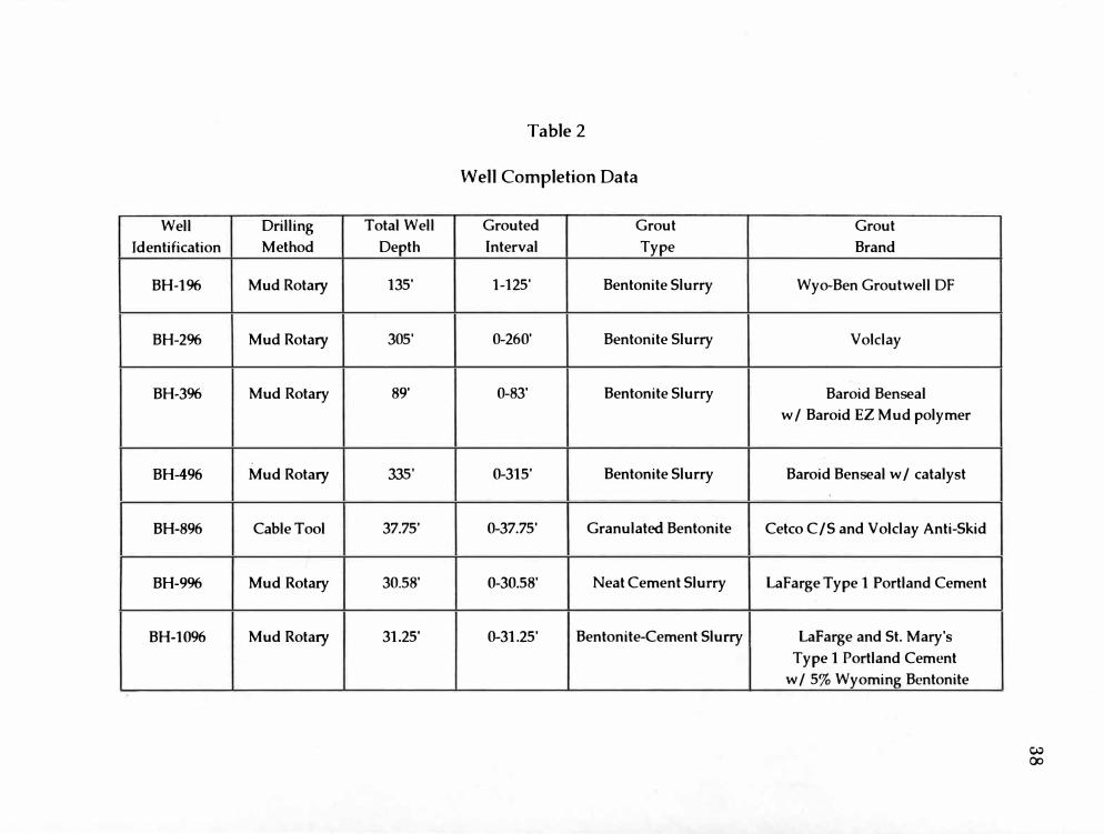
2. Well Comple tion Data.............................................................................. 38
3. Grout Property Comparison Table ......................................................... 42
4. A Comparison of Water Wel1 Grouting Materials ............................ 60
viii

LIST OF FIGURES
1. Example Calculation of the Percentage of Cable Tool AnnularWell Space Filled....................................................................................... 13
2. Dril1 Cuttings Bridging in Annular Space of Water Well................ 18
3. Drilling Mud Solids Settling in Annular Space of Water Well...... 19
4. Site Map....................................................................................................... 29
5. \'Ve)] Field Diagram................................................................................... 30
IX
INTRODUCTION
Statement of Problem
Groundwater is an important natural resource that requires diligent
conservation and preservation. Environmental awareness has prompted
many changes in regulations to help to protect groundwater. With those
changes have come strict water well instal1ation codes.
If groundwater is contaminated it can no longer be used to its fullest
potential, if at all. Water wel1s can be a source of contamination if they
have not been instaJled correctly, or if the grouting material used to sea]
the we11 has "failed." Water wells with either of these problems can
provide a direct pathway for contamination to migrate downward from the
surface, or possibly allow inter-aquifer exchange to occur. Either of these
situations could cause contamination of water we11s.
The numerous problems encountered in grouting water wells and
the importance of a good water well seal has prompted state regulators and
the water we11 industry to seek solutions and answers.
Many products exist for the purpose of sealing a well, as do many
techniques for wel1 installation. Most techniques have welJ known
weaknesses that are addressed in regulations; therefore most are not in
1

question. However, questions concerning product performance are
abundant.
Water well grouting materials range from neat cement to bentonite
slurries and everything in between. Each has limitations. A number of
factors determine if a grout can be instal1e·d correctly and maintain its
integrity. "A good grout should provide adequate percent solids to create a
low-permeability seal, have a long-term physical integrity to remain intact
in the hole and not settle, and have practical mixing and pumping
capabilities" (Riewe, 1996, p. 29).
Properties that may affect water well grout integrity need to be
understood to help to prevent groundwater contamination. To evaluate
some of those properties a field study was conducted using several
grouting materials.
Variability between the grouts and dril1ers prohibited a well
controlled study; however, the intent of this study is to compare "real
world performance" of grout types and drillers. The properties of the
grouts could change depending upon the driller's methods of installation,
the depth of the well, and the formation in which the well is placed. In an
attempt to minimize the differences between drillers, company
representatives oversaw the installation of the bentonite slurry grouts used
in this study. The cement grouted and the bentonite-cement grouted wells
were both installed according to common drilling practices. The cable tool

well was installed by the driller who developed the grouting method used.
AU of those involved in this study understood that the purpose of the
wells was to evaluate grouting materials, and to some extent the grouting
methods. The wel1s used in this study were intended to represent the best
case scenario.
Most of the resources used in the literature review came from water
well industry journals or other sources, in an attempt to utilize the
knowledge and understandings of water well drillers. Michigan state codes
and regulations were also important sources of information.
Purpose of Study
The purpose of this study is to evaluate the properties of �he
different grouting materials that may affect the integrity of a water well seal
in light of findings from previously published studies and articles, and
knowledge available from industrial and governmental sources.
In order to answer the questions concerning grouting problems an
in-depth literature review was conducted to help define the problems. A
field study was conducted to evaluate some of the properties of various
grouting materials. The literature review provided insight into how
grouts are applied in the water well industry and why some grouts simply
do not provide an adequate seal. It also provided an extensive knowledge
of the properties that are of concern in establishing a good water well seal.

The field study provided base-level information about the properties that
may affect the integrity of a water well seal, and a direction for future
studies.
LITERATURE REVIEW
Introduction
Grouting, as defined by the Michigan Department of Health
(MDPH), means:
The placement of grout into the annular space that surrounds a permanent casing for the purpose of sealing the annular space to prevent the entrance or migration of surface water, near surface water, and contaminants to the groundwater and to maintain the natural protection of aquifers (MDPH, 1994, p. 8).
"As it pertains to groundwater protection, the objective of grouting
is 'to establish and maintain a seal, against all faces of the void, that is of
equal or lower permeability than that of the best formation intersected"'
(Stichman, 1990, p. 1). The best formation means the least permeable layer
encountered.
Sealing of water wells has evolved over the years from the use of
drill cuttings and drilling mud, to neat cement, to various bentonite
grouting materials. Each one has its own limitations.
Bentonite
Bentonite refers to a rock that contains montmorillonite as its chief
mineral. Bentonite, as defined by the MDPH, is "a plastic colloidal clay
which has an extensive ability to absorb fresh water and swell in volume
5

and which is composed predominantly of the mineral montmorillonite"
(MDPH, 1994, p. 6).
Although there are bentonite deposits found throughout the world,
the bentonite most commonly used in the water-well industry was made
by volcanic ash that was deposited during the Cretaceous period, east of
Idaho, in a sha11ow, calm, inland sea. As the ash was deposited it began to
react with the sea water (Bentonite Corp., 1997). Bentonite was formed �
the alteration of the volcanic ash in situ (Grim, 1953). It seems that several
factors must exist for the alteration of ash to bentonite to occur. The
alteration from volcanic ash to bentonite takes place in saline water, not
fresh water. Also, the ash must contain a moderate amount of MgO. Ash
without magnesia does not alter to montmorillonite (Grim, 1953). After
the ash had been deposited in the sea it was covered with silt and mud
layers. This sequence of events happened several times, with over fifty
layers of bentonite being deposited within one thousand feet of sediment.
With continental plate movement, these beds were raised and the sea was
drained. Bentonite beds are currently being mined in Wyoming and South
Dakota (Bentonite Corp., 1997).
The chemical and mineral makeup of individual bentonite beds
varies greatly. This is due to the complexity of the formation of bentonite.
The source rock of the volcanic ash could vary in composition, thereby
changing the chemical makeup of the bentonite. The salinity of the sea in
which the vokanic ash was deposited cou]d have varied over time and
over regions, thus affecting the altering process. A wide assortment of
variable factors played an important role in the chemical and mineral
content of bentonite.
Montmorillonite is a type of smectite ·clay. Smectites are swel1ing
clays that attract water between the sheet layers of its structure. The ]arge
surface area of the sheet ]ayers alJow water to be adsorbed in large
quantities, thus greatly increasing the volume of the clay (Velde, 1992).
Montmorillonite contains exchangeable cations within its structure.
The nature of the exchanged cation found in bentonite can affect the
properties of the clay. "Water adsorption of the sodium form of
montmorillonite was three times greater than that of the calcium form,"
(Grim, 1941, p. 9) thus making sodium bentonite more desirable for sealing
wells. Large deposits of sodium bentonite are found in Wyoming.
Bentonite is used for many industria] purposes, dependent upon its
properties. Bentonite is used for kitty litter and in cosmetics and
pharmaceutical products. It is used to help strengthen sand molds i n
foundry work. It is a]so used as a suspension agent in insecticides,
pesticides, herbicides, and fertilizer blends. Bentonite has also been found
to be very useful in the oil and gas, and water well drilling industries
(American Colloid Company, 1997). This is by no means a complete list of
the uses of bentonite.

In the water well industry, bentonite is used in drilling mud, and it
is used to seal wells. The difference between drilling mud and sealant is
the bentonite solids content. In general, drilling muds have a low solids
content of 3 to 9% with the remainder largely water (Stichman, 1990).
Bentonite slurry grouts used to seal wells are made using 20 to 35% solids.
When properly applied, bentonite can provide an excellent seal for
water wells. Bentonite has a very slight heat of hydration, and it forms a
low permeability, flexible seal that will rehydrate if dried (Papp, 1994).
Unlike cement it does not greatly affect the pH of groundwater. Bentonite,
in general, adheres very well to all surfaces (Smith & Mason, 1985). "This
abiJity to adsorb water and swell, exerting pressure against confining
surfaces, is what gives the material its tremendous advantages over other
mediums for filling void spaces in boreholes" (Stichman, 1990, p. 5). It is
often assumed that bentonite does not have problems adhering to any type
of casing. However, Edil et al. (1992) reported that Voklay, a brand of high
solids bentonite, does not adhere to steel casing. In fact, the Voklay grout
observed in Edil's study seems to form a micro-annulus similar to that
noted in PVC wells grouted with cement. Edil's study does not address the
adherence of Voklay to PVC casing. · Is there a difference between
adherence to PVC or steel well casing? Are there differences in the
performance of the various grout brands?
Bentonite comes in various forms for use in the water we11 industry:
powdered, granulated, chips and tablets. Powdered bentonite is mixed with
water to form a slurry either for drilling mud or grouting. Granulated
bentonite is often used in the water well industry to seal cable tool wells.
Chips or tablets have been used to seal wells by dropping them into the
annular space surrounding the well casing. While it is true that bentonite
has the potential to provide a good seal, each of method of application has
notable problems.
Bentonite Slurry Grouts
Regardless of the percent solids, bentonite slurry grouts are prone to
excessive settling. The Michigan Department of Public Health Well
Construction Unit, reports that well drillers and inspectors have noticed
"settling of 20 to 75 feet, when products have been mixed and applied in
accordance with the manufacturer's recommendations" (Gaber, 19%, p. 1).
Several theories exist that try to explain this phenomenon. One
theory is that the grout is intruding into the surrounding formations.
Another theory is that the grout is losing water to porous formations, thus
causing settling to occur. Most literature. assumes that either one or the
other of these theories is true. Another theory is that additives, such as
polymers and catalysts used to control bentonite swell and extend working
time, affect the gel strength of the bentonite. This may cause the bentonite

10 in deeper wel1s to wash out into the formation (Gaber, 1997). No pub1ished
experimental studies on the settling of bentonite s]urry grouts could be
found.
In addition to settling problems there are several questions
concerning the long-term integrity of bentonite grouts. Does bentonite
provide a good seal in the v adose zone? In a field study performed �
Lyndon Bucher it was found that high solids bentonite slurry grout has the
ability to "maintain a high degree of hydration and provide a competent
seal above the water table, even in very low moisture conditions" (Bucher,
1993, p. 40).
Another question concerning bentonite grouts is its ability to remain
in place below the water table, and in flowing-well or artesian situations.
Does the natural flow of water affect the integrity of a bentonite slurry
grout? No literature could be found on the long-term effects of normal
water flow below the water table on bentonite grouts. Does water under
pressure, as in a flowing-well or artesian situation, affect the integrity of a
bentonite slurry grout? Ogden and Ruff (1993, p. 249) suggest that
bentonite slurry grouts do not have the strength to resist water under
pressure and should not be used "in confined aquifer boundaries without
additional mechanical support such as packers or adjacent cementitious
seals, unless the aquitard thickness is at least two-thirds of the expected
maximum drawdown." Local regulations should be checked before using
11 packers or sealing a flowing we]] to determine the recommended practices
for that area.
Several other questions exist regarding bentonite grouts. How do
the various brands of grout compare to each other? Is long term integrity a
problem for bentonite slurry grouts? How do various additives affect grout
integrity? Clearly research on several aspects of bentonite grouts is badly
needed.
Granulated Bentonite
Granulated bentonite can be used to seal the borehole surface and
the top few feet of a diy borehole (Bertane, 1987). A more important use of
granular bentonite is as a grout for cable tool wells.
To seal a cable tool driven well, granulated bentonite is heaped
around the we]] casing at the surface and replenished as needed. As the
well casing is being driven the bentonite follows the casing down the
borehole. The effectiveness of this practice in providing an intact seal
around the well is an ongoing research topic at Western Michigan
University.
In an attempt to ensure proper grout placement, oversized sleeves
may be welded to the well casing at regular intervals. These sleeves help to
trap and to drag additional grout down the borehole. However, questions
exist about the effectiveness of these sleeves. Does the grout become

12
trapped only around the sleeves? Or do the sleeves help to distribute the
grout evenly?
Another way to help to ensure proper grout placement for cable tool
wells is to raise and lower the casing several times throughout the drilling
process (see Leonard, 1985). This method is quite effective; however, it is
very time consuming and there are questions as to its effectiveness with
depth. Because of these problems, this method is not commonly used.
No published literature could be found about any concerns
regarding this grouting method. However, researchers at Western
Michigan University, speculate that if neither of the above mentioned
methods of ensuring proper grout placement is used, grout thickness will
diminish with depth until only a smearing of grout can be found. Further
physical studies need to be conducted on the various methods of grouting
cable tool wells.
In a study conducted by the MDPH Wel1 Construction Unit (Gaber,
1997), actual volumes of dry granular bentonite needed to seal the borehole
of a cable tool well were calculated, then bentonite usage was compared
with the calculated volume to determine the percentage of annular space
filled. Please see Figure 1 for an example of these calculations. Using these
simple formulas four cable tool contractors' bentonite usage was compared.
Table 1 shows a number of wells used for the Gaber (1997) study, the range

______________________________13If using 4-inch casing with an outer diameter of 4.5 inches, and a
drive shoe with an outer diameter of 5.2 inches, the annular space is 0.35
inches and yields an annular space volume of 0.0329 cubic feet per linear
foot. A SO-pound bag of granular bentonite yields 0.7 cubic feet.
Example: A contractor installed 5754 linear feet of well casing m a
year. To determine annular space volume:
5754 linear feet x 0.0329 cubic feet per linear foot
=189.3 cubic feet
189.3 cubic feet/0.7 cubic feet per bag
=270 bags of granular bentonite
The contractor reported using 240 bags of bentonite for the year.
240 bags/ 270 bags
=88% of the annular space volume filled
Figure 1. Example Calculation of the Percentage of Cable Tool AnnularWell Space Filled (Gaber, 1997).

14 Table 1
Granulated Bentonite Use of Selected
Michigan Cable Tool Operators
Contractor Data and Percentages
Contractor Number 1 2· 3 4
Number of Wells 621 165 45 15
Casing Depth
Range (feet) 19-237 19-237 25-272 25-145
Average Casing
Depth (feet) 83 83 84 58
Total Casing
Footage 54,866 13,713 3,814 874
Total Bentonite
Usage (lbs) 84,450 50,275 9,247 1,675
Bentonite Usage
Rate (lbs/ ft) 1.53 3.67 2.42 1.92
Percentage of Annular
Space Filled 65% 156% 103% 82%
(adapted from Gaber, 1997)
15
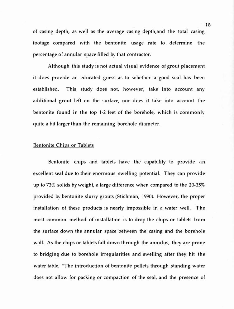
of casing depth, as well as the average casing depth,and the tota1 casing
footage compared with the bentonite usage rate to determine the
percentage of annular space filled by that contractor.
Although this study is not actual visual evidence of grout placement
it does provide an educated guess as to whether a good seal has been
established. This study does not, however, take into account any
additional grout left on the surface, nor does it take into account the
bentonite found in the top 1-2 feet of the borehole, which is commonly
quite a bit larger than the remaining borehole diameter.
Bentonite Chips or Tablets
Bentonite chips and tablets have the capability to provide an
excellent seal due to their enormous swelling potential. They can provide
up to 73% solids byweight, a large difference when compared to the 20-35%
provided by bentonite slurry grouts (Stichman, 1990). However, the proper
installation of these products is nearly impossible in a water well. The
most common method of installation is to drop the chips or tablets from
the surface down the annular space between the casing and the borehole
wall. As the chips or tablets fall down through the annulus, they are prone
to bridging due to borehole irregularities and swelling after they hit the
water table. ''The introduction of bentonite pellets through standing water
does not allow for packing or compaction of the seal, and the presence of

16
voids and inhomogeneities resulting from bridging are likely" (Dunnivant
et al., 1997).
In 1994, grouting of wells by pouring bentonite chips into the
annulus was banned in the revised Michigan Well Construction Code
(MDPH, 1994).
Drill Cuttings and Drilling Mud
Today drill cuttings and drilling mud are no longer considered
viable well grouting materials. "Drill cuttings were not effective because
they often bridged and could not be compacted to form a good seal.
Drilling mud was not effective because of low bentonite solids
concentration in the slurry" (Oliver, 1995, p. 12).
Drill cuttings, in most cases, do not meet the permeability criteria of
a grout. "A grouting material should have a permeability equal to or lower
than the permeability of the least permeable formation penetrated"
(MDPH, 1988, p. 19). This means that the grout should transmit water at an
equal or lesser rate than the native soils or rocks, thus retarding the
movement of fluids (MDPH, 1988). Drill cuttings are a mixture of all
formations penetrated by the drill bit. This mixture, in most cases, will
have a higher permeability due to the fact that it is a mixture of all the
formations, not just the least permeable formation, and because it has been
disturbed it is less dense and more permeable. When a formation is

disturbed the natural layering and consolidation is destroyed, resulting in a
less permeable material.
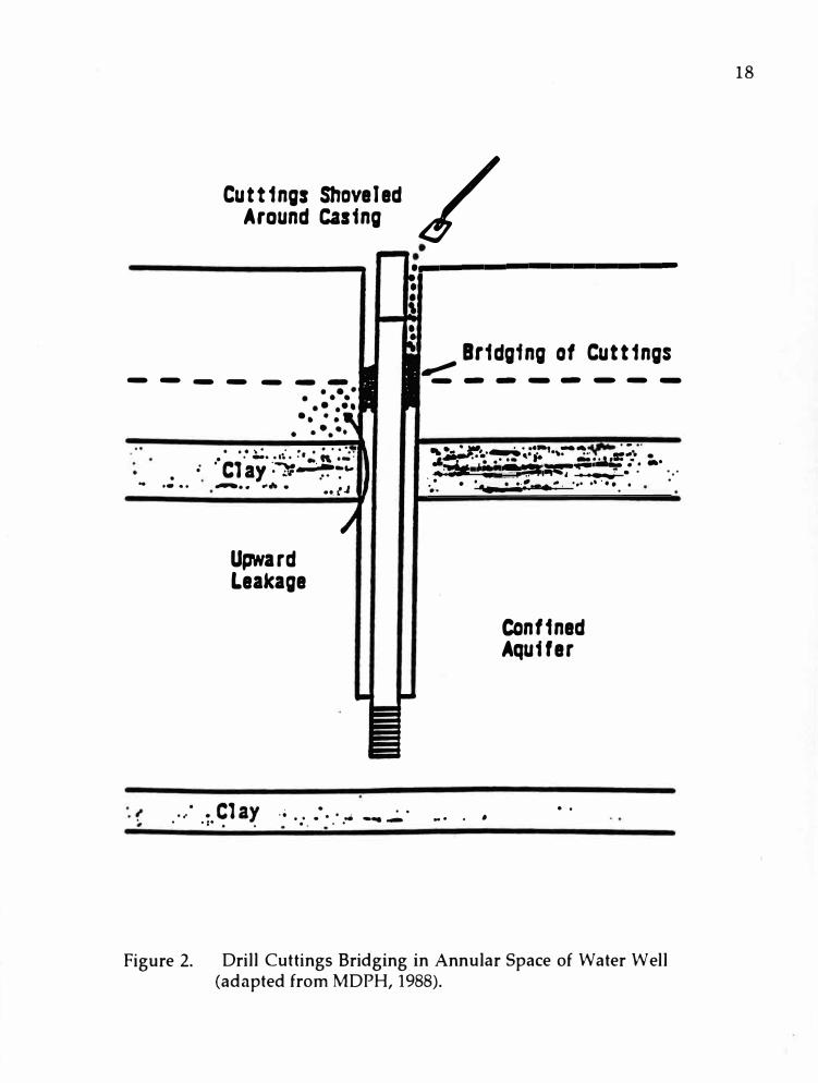
Bridging is a common problem when drill cuttings are used to sea] a
we11 (Figure 2).
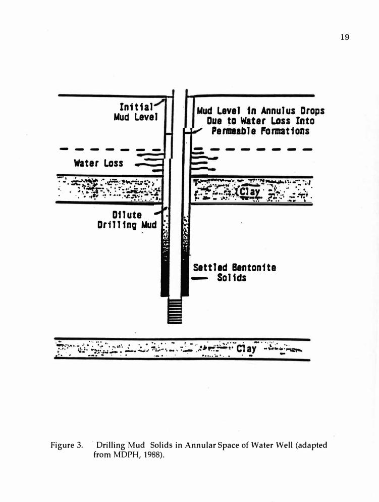
Because of the low solids concentration· of drilling mud it cannot be
used as a grout.
A low solids [usually 3 to 9%] drilling mud or mud/ cuttings combination will drop in the annulus as the mud level seeks the water table level. Settling of solids generally occurs, resulting in few or no solids in the upper portion of the annulus. Water loss to permeable formations occurs and the mud level along the casing drops, often without borehole collapse (MDPH, 1988, p. 13).
Figure 3 illustrates a well in which drilling mud has settled. ''The trouble
is, in some cases, that the mud slurry disappears down the annulus,
leaving an open void that can allow contamination to easily flow into the
well" (Riewe, 1996, p. 29).
Edi] et al. (1992) cautioned against the use of drilling mud as a
grouting medium. However, their research indicated that heavy drilling
muds entrained with sand, having a weight of at least 11 pounds per
gallon, were capable of providing an adequate seal. Subsequent research
made it quite obvious that " the use of rotary drilling mud and cutting
slurries was not, in many cases, providing an adequate grout even with
our new mud weight requirement" (Riewe, 19%, p. 32). It was found that
17
Cuttings Shoveled / Around casing
-----
. . . \. . . . ·• .. · .. . . -· .. ,. .. , .. "·-·. ; . Clay ��--':':"-:.,_
.. •• •• .-.. •• .,,,,_ • ••.l'
Upward Leakage
. . .. ·• ·: . ·.· ... � ......
·-------------
• • 8r1dgfng of cuttings
.,,,,,,--- - - - ---
... . � . . .... ---.... .
,.....,..�•-.,•.:.. '""• .. __ .. .
-'5il ·= .. - .- :-·,;,ar;- .- . -· ... . = •"'·� . .... . . . .. ·-:. . -�:. ...-: . ... ····•..
.
.. . . .
Confined Aquifer
. .
Figure 2. Drill Cuttings Bridging in Annular Space of Water Well (adapted from MDPH, 1988).
18
Ini t1a1 Mud Level
-------
Water Lass
D11uta Dr1111ng Mud
Mud Level tn Annulus Drops Due ta Water Lass Into Permeable Formations
-------
,,,� 11'11�·--.... �--,., ....... ,, ........ , .,. ... ·••.:a-Ii" ......... - ... . • .. . � ·':..----...... ·c1 · .,,,. · .. · · · · ;�. ,,. ....... . . ..'•• • ;. ... OT ... t •i �·• •• • :'r.f
,.. -- · .... .............. ·.... -f.�:·· .�-:-. � .
Settled Bentonita - So11ds
. .. . . . •, ·:. .. ' . . . . .. . . .. , - ,. . ... � .... . ... . ... . � ···.• ............ " · · · ·· • ... ,. , • - • - · • .., ___ ,. Clay � ... · ·.-•·· . ,?.: . .. ..,..; • • . ..... ....,,,.. •·a, ...... �...... .... ....-... . .. ---�-.... t . ... • ...... .,,... • . .. . . � --· .. . . . .-- . . . ......... •·. . . -
Figure 3. · Drilling Mud Solids in Annular Space of Water Well (adaptedfrom MDPH, 1988).
19

heavy drilling muds were difficult to pump, caused borehole instability
and poor circulation, and cuttings were not dropped into the mud pit
(Riewe, 1996).
The same study tested several grouting materials in the laboratory
(Riewe, 1996).
It was found that low solids drilling muds failed as grouts. They al1owed excessive infiltration, exhibited decisive subsidence (in some cases greater than 100 percent by volume), and had many cracks that allowed dye to easily migrate down through them. This is not surprising when one considers the fact that these slurries are significantly greater than 90 percent water by volume (Riewe, 1996, p. 31).
Field tests confirmed laboratory results in Riewe's study.
The evidence shown in previously published studies seems to
indicate that drilling mud and drill cuttings should not be used for
grouting.
Cement
The most commonly used cement grout is a neat cement slurry.
Neat cement is a combination of Portland cement and water. No sand or
gravel is added (MDPH, 1988). Portland cement is composed of lime, silica,
alumina and iron oxide (Portland Cement Association, 1965) heated to
form a variety of compounds that react readily with water. These
components can be derived from a number of sources. Type I Portland
20
21
cement is general purpose and is the type most used in the water well
industry. It should be noted that Type I cement will not resist sulfate
attack. This may be important to the integrity of a seal in an area where
acid rain occurs.
Neat cement has been used in the oil· and gas industry successfulJy
srnce the early 1900's (Smith, 1976). "Petroleum industry cementing
techniques have become highly speciaJized and apply to water well
construction, although this transfer of cementing technology has not
progressed as we11 as in other areas" (Department of Army and Air Force,
1975, p. 288). There are several possible explanations for the lack of transfer
of technology between the oil and gas industry and the water well industry:
1. As cement is mixed with water a chemical reaction occurs. This is
an exothermic reaction that produces heat and is called heat of hydration.
In the past it was thought that heat of hydration caused structural damage
to PVC casing. Although PVC deformation is unlikely (Kurt, 1979), it may
occur under certain circumstances. If a non-uniform borehole is
constructed, or if washouts developed during construction, a thicker than
normal column of cement can increase the chance of deformation to occur.
Very few documented cases of deformation caused by the heat of hydration
have been recorded in Michigan.
Many contractors routinely cement PVC casing in Michigan. It is beJieved that the lower ground water temperature and relatively high static water levels contribute to a reduction i n
heat of hydration damage. Michigan's minimum PVC casing size of 5 inches may also result in masking heat of hydration damage. If a slight casing deformation occurs it may not be noticed when the 4 inch submersible pump is installed, whereas if 4 inch PVC were allowed, as in other states, the deformation would be apparent (Gaber, 1997, p. 1).
2. Bentonite slurry grouts can often be mixed using the same
equipment used for mixing drilling mud, whereas dri11ers often prefer
separate mixing and pumping units for cement. To avoid pump failure,
extensive flushing and cleaning is required after pumping cement. To
help to assure that a working pump is found on the drill rig, a separate
pump is often used for cement. Thus, cement grout requires an extra effort
on the drilJer' s part, so unless cement grout is required or requested,
bentonite slurry grouts are often preferred.
3. Neat cement grout cannot be used in monitoring wells or
environmentally sensitive wells because it often raises the pH of
groundwater (Dumouchelle et al., 1990). Elevated pH levels may also be
found in drinking water wells.
4. As neat cement cures, a micro-annulus or fracture network may
develop around the well casing allowing leakage to occur down the casing
(MDPH, 1988). This micro-annulus has been well documented in several
studies. Cement, even cement with bentonite added to it, had the tendency
"to adhere to one surface, but not the other in a borehole" (Smith and
Mason, 1985, p. 36). Oliver noted that cement grouts shrink and crack after
22

23
having setup, thus "leaving areas where contaminants could migrate into
the wel1" (Oliver, 1995, p. 12). Bertane (1987, p. 3) also noted, "Cement
grout shrinks when set, creating a micro-annulus space in the borehole
causing inter aquifer transfer."
The documentation of a micro-annulus is most prevalent with the
use of PVC well casing and cement. No information could be found
indicating if a micro-annulus forms when steel casing is sealed with
cement grouts.
Not all factors affecting the formation of a micro-annulus are
understood or known. Does this micro-annulus form only near the
surface? Or does it extend the full length of the casing? Does hydrostatic
pressure affect the adherence of cement? One study reports that the micro
annulus found in wells used in their research extended for a limited
distance only (Edil et al., 1992). Oliver (1991) also reported the same results
from a study he observed. Can PVC well casing be made less smooth, so
that cement will adhere to it better?
Other questions also exist. How often does this micro-annulus
form? Does it only form in the vadose zone? Or does it also form i n
saturated conditions? How does the addition of bentonite to cement affect
the formation of a m icro-annulus?
Understanding more about the conditions under which a micro
annulus forms would greatly improve the proper use of cement grouts in
the water well industry.
Bentonite-Cement Grouts
The addition of bentonite to neat cement is alleged to augment. the
set volume of cement, reduce or eliminate shrinkage, inhibit water loss,
and reduce the density of the cement (Smith, 1976). With alJ of these
improvements it would seem as though bentonite-cement grouts would be
the best grout ever invented. ''The truth of the matter is that a cement
bentonite grout is stiJI a cement grout. Adding small amounts of bentonite
to cement grout does not greatly change its properties" (Mclarty, 1993, p.
29).
In fact, the field study conducted at Western Michigan University, as
well as other studies, have shown that the addition of bentonite to a neat
cement grout actually increases the potential for fracturing to occur. Riewe
(1996) reported that bentonite-cement grouts were found more likely to
fracture than cement grout. One likely reason for this phenomenon is the
incompatibility of cement and bentonite.
The introduction of cement to a bentonite can seriously effect [sic] bentonites ability to hydrate. Cement releases Ca++ and OH- ions this flocculates the bentonite day. The day platelets structure is destroyed and the day looses its ability to hold water, the day shrinks and does not provide a good seal (Bertane, 1987, p. 4).
24

Another theory suggests that alkalis from bentonite are released
when the clay and cement are mixed, causing the pH to rise even higher
than in straight cement. This rise in pH affects the alignment of the clay
platelets, causing the clay particles to flocculate. A high pH also raises the
solubility of the silica contained in the cement. This dissolves the quartz,
an integral part of cement, causing a silica gel to form, making the cement
weak. The overall effect of the above mentioned reactions are a definite
concern but they are not fully understood, and it is hard to determine the
exact effect that they produce in grout. Under these circumstances the
addition of bentonite to cement is not advisable.
This also brings to mind questions concerning the logic of placing a
cement cap on a well sealed with bentonite grout. Will a cement cap i n
contact with bentonite slowly change the properties of the bentonite? How
will the contact between the cement and bentonite affect the long-term
integrity of the bentonite seal? In a study reported by Oliver (1991), a
bentonite tablet seal appeared to be damaged by leachate from cement
placed above it.
The tablets did not hydrate as much as in the other model [where only bentonite was used] and they changed color near the top. The tablets under the bentonite grout could absorb water that was in the sand below, but the tablets under the cement could not (Oliver, 1991, p. 41).
25

Discussion
While there is quite a bit of literature regarding water well grouting
issues, there are still many unanswered questions concerning grout
integrity.
Bentonite, in any of its many forms, has the potential to provide one
of the best seals available at this time. Nonetheless, problems do exist that
warrant further studies. Bentonite slurry grouts have been known to settle
excessively. Bentonite chips and tablets when installed from the surface
tend to bridge. Granular bentonite in cable tool wells may or may not be
achieving a proper seal. All of the problems listed here and the questions
mentioned earlier seem to argue that a lot of research remains to be
conducted on the use of bentonite as a grout.
Drill cuttings and drilling mud are not, for the most part, considered
to be good sealing mediums for water wells.
Cement and bentonite-cement grouts have well documented
problems. Cement grouts have a tendency to form a micro-annulus
around the well casing. Bentonite-cement grouts have the surprising and
most disturbing propensity for developing fractures. Given the successful
use of cement grouts in the oil and gas industry, more efforts should be
directed to the transfer of this technology to help increase successful use of
these grouts in the water well industry.
26
27
The limitations of each grouting medium must be resolved.
Further research should be conducted on each grout type, and additional
product development should be promoted.

FIELD STUDY
Introduction
In an attempt to answer some of the questions about grouts and to
provide a baseline study for future reference, a field study was conducted
on Western Michigan University campus. This study compares several
different grouting materials commonly used in the water well industry and
focuses on a number of properties that may affect the integrity of a water
well seal.
Site Description
Location
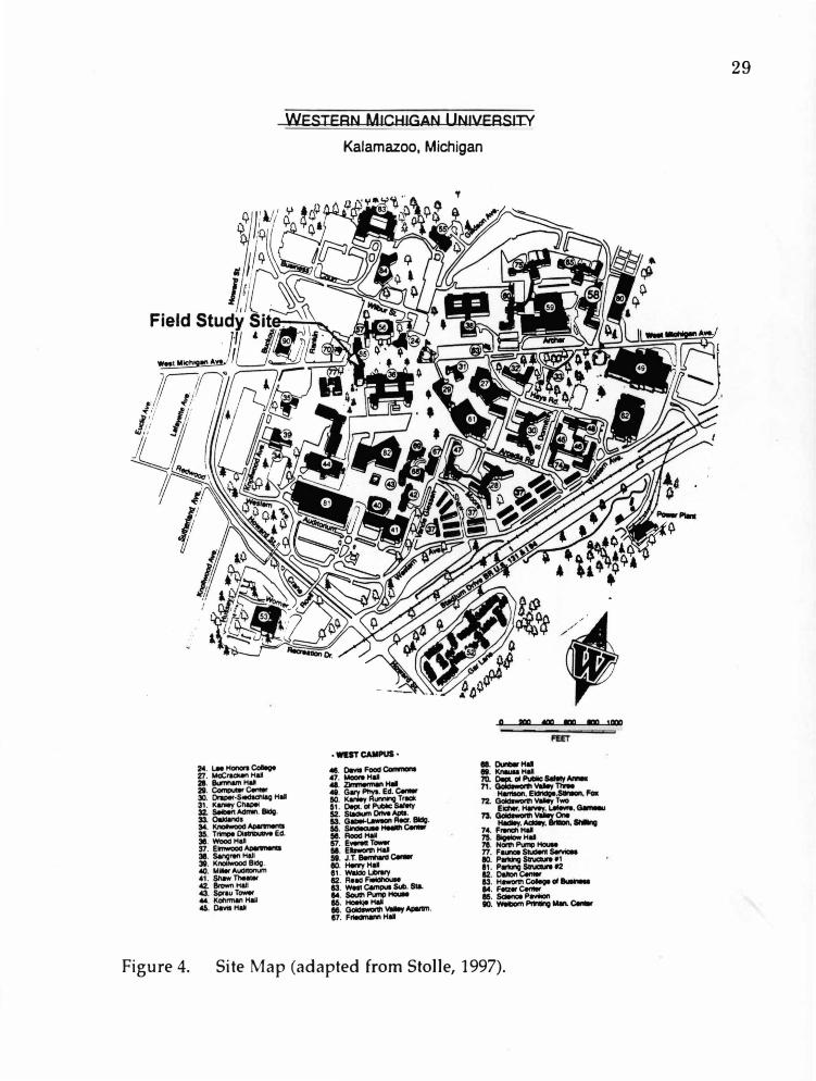
This study was conducted on wells installed on the Western
Michigan University campus, Kalamazoo, Michigan (see Figure 4). Seven
wells were placed in a mini-well field (see Figure 5) in an area that was
later excavated for the future basement of the new science pavilion. Four of
the wells were installed as test wells, to be used by the Geology Department
of Western Michigan University after the completion of the science
pavilion. The three remaining wells were installed solely for the purpose
of this study and have since been removed.
28
WESTERN MICHIGAN UNIVERSITY
Kalamazoo, Michigan
0 IIIO «IO IOO IOO 1000
Figure 4. Site Map (adapted from Stolle, 1997).
29
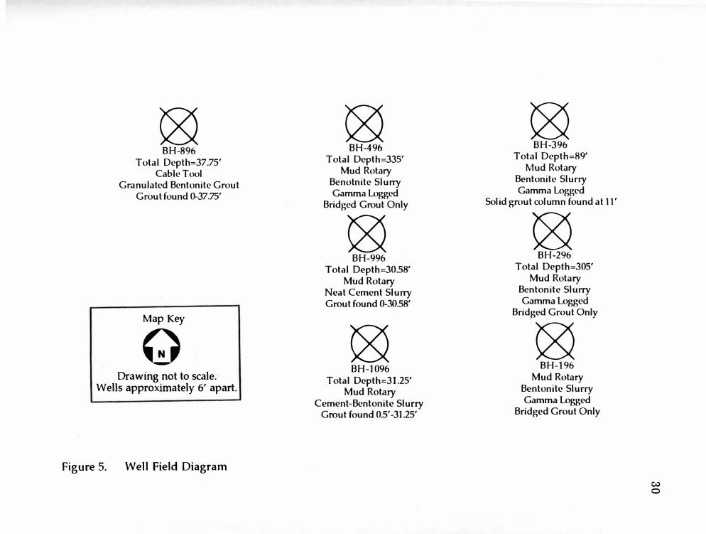
� BH-896
Total Dcpth=37.75' Cable Tool
Granulated Bcntonitc Grout Grout found 0-37.75'
Map Key
Q-Drawing not to scale.
Wells approximately 6' apart.
Figure 5. Well Field Diagram
� BH-496
Total Depth=335' Mud Rotary
Benotnitc Slurry Gamma Logged
Bridged Grout Only
� BH-996
Total Depth=30.58' Mud Rotary
Neat Cement Slurry Grout found 0-30.58'
� BH-1096
Total Depth=31.25' Mud Rotary
Cement-Bentonite Slurry Grout found 0.5' -31.25'
� BH-396
Total Dcpth=89' Mud Rotary
Bentonitc Slurry Gamma Logged
Solid grout column found at 11'
� BH-296
Total Depth=305' Mud Rotary
Bentonitc Slurry Gamma Logged
Bridged Grout Only
� BH-196
Mud Rotary Bentonite Slurry Gamma Logged
Bridged Grout Only
C,lj
0

Geology
The geology of this site is typical of glacial outwash deposits. Kirby
(1996) logged alternating layers of sands and gravels during drilling (see
Appendix A). The sands were welI sorted/poorly graded, medium
grained, tan, with few fines, and some smaII to large gravel. A grave] layer
was located at approximately 8 feet below grade and was approximately 6 to
10 inches thick. The gravel was medium to large and mixed with some
day. More sand and gravel layers are present below the excavation depth,
as indicated by the wel1 Jogs.
31
The water table at this site is at approximately 80 feet. The welis
were excavated to a depth of about 13 feet. Hence, this study focuses o n
vadose zone grouting.
Methods
Well and Grout Installation
Professional water well drillers, licensed by the State of Michigan,
installed all seven wells used in this study. The drilling companies who
participated in this study were: Raymer Drilling Company of Marne,
Michigan; Dewind Drilling Company of Zeeland, Michigan; Stearns
Drilling of Dutton, Michigan; Katz Drilling of Battle Creek, Michigan; and
32
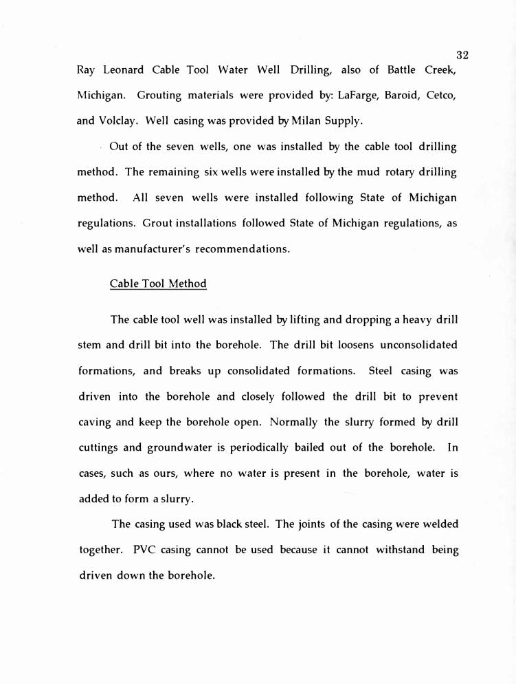
Ray Leonard Cable Tool Water Well Drilling, also of Battle Creek,
Michigan. Grouting materials were provided by: Lafarge, Baroid, Cetco,
and Volclay. Well casing was provided by Milan Supply.
. Out of the seven wells, one was installed by the cable tool drilling
method. The remaining six wells were installed by the mud rotary drilling
method. All seven wells were installed following State of Michigan
regulations. Grout installations followed State of Michigan regulations, as
well as manufacturer's recommendations.
Cable Tool Method
The cable tool well was installed by lifting and dropping a heavy drill
stem and drill bit into the borehole. The drill bit loosens unconsolidated
formations, and breaks up consolidated formations. Steel casing was
driven into the borehole and closely followed the drill bit to prevent
caving and keep the borehole open. Normally the slurry formed by drill
cuttings and groundwater is periodically bailed out of the borehole. In
cases, such as ours, where no water is present in the borehole, water is
added to form a slurry.
The casing used was black steel. The joints of the casing were welded
together. PVC casing cannot be used because it cannot withstand being
driven down the borehole.
33
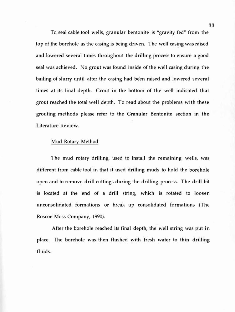
To seal cable tool wells, granular bentonite is "gravity fed" from the
top of the borehole as the casing is being driven. The we11 casing was raised
and lowered several times throughout the drilling process to ensure a good
seal was achieved. No grout was found inside of the well casing during the
bailing of slurry until after the casing had be·en raised and lowered several
times at its final depth. Grout in the bottom of the well indicated that
grout reached the total well depth. To read about the problems with these
grouting methods please refer to the Granular Bentonite section in the
Literature Review.
Mud Rotary Method
The mud rotary drilling, used to install the remaining wells, was
different from cable tool in that it used drilling muds to hold the borehole
open and to remov� drill cuttings during the drilling process. The drill bit
is located at the end of a drill string, which is rotated to loosen
unconsolidated formations or break up consolidated formations (The
Roscoe Moss Company, ]990).
After the borehole reached its final depth, the well string was put i n
place. The borehole was then flushed with fresh water to thin drilling
fluids.

34
Two different types of tremie pipes were used to place the filter packs
and grouts in the boreholes. The traditional tremie pipe is a hollow steel
pipe. The other option used was disposable black tubing.
The traditional tremie pipe was placed at the bottom of the borehole
between the well casing and borehole wall. The filter pack was then placed
into the borehole through the tremie pipe. The tremie pipe was raised as
the filter pack was installed. After the filter pack was in place, the tremie
pipe was pulled back above the filter pack and grouting was begun. Grout
was pumped through the tremie pipe from the top of the filter pack to the
surface. When the grout reached the surface it was weighed to ensure that
it has the proper weight. This grout weight may not have been the same as
what was sent down the tremie pipe because the grout may have mixed
with water found in the borehole. If this was the case, fresh grout was
pumped down through the tremie pipe until the grout at the surface was
the proper weight. After grouting was completed, the traditional tremie
pipewas removed.
The disposable tremie tube wasused in the cement wells. This tube
was cut off at the surface and left in place. Leaving the tremie tube in place
is not a recommended practice.
The grout was then allowed to set. If excessive settling occurs, it may
be necessary to addmore grout at a later date. However, this was not done
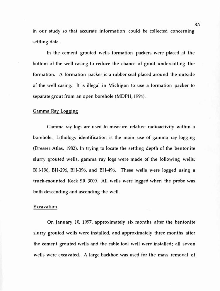
35 m our study so that accurate information could be co11ected concerning
settling data.
In the cement grouted weJls formation packers were placed at the
bottom of the welJ casing to reduce the chance of grout undercutting the
formation. A formation packer is a rubber seal placed around the outside
of the we11 casing. It is illegal in Michigan to use a formation packer to
separate grout from an open borehole (MDPH, 1994).
Gamma Ray Logging
Gamma ray logs are used to measure relative radioactivity within a
borehole. Lithology identification is the main use of gamma ray logging
(Dresser Atlas, 1982). In trying to locate the settling depth of the bentonite
slurry grouted wells, gamma ray logs were made of the following wells;
BH-196, BH-296, BH-396, and BH-496. These we11s were logged using a
truck-mounted Keck SR 3000. All wells were logged when the probe was
both descending and ascending the well.
Excavation
On January 10, 1997, approximately six months after the bentonite
slurry grouted wells were installed, and approximately three months after
the cement grouted wells and the cable tool well were installed; all seven
wells were excavated. A large backhoe was used for the mass removal of
36
soils, and detail digging was done by hand. The wells were excavated to a
total depth of approximately 13.3 feet below the original grade.
Photographs and detailed field notes were taken throughout the excavation
(Callaway, 1997).
On the day of the excavation temperatures were below freezing, with
wind chill factors below zero. It is not known if these extreme
temperatures affected bentonite settling data, or any other grout
characteristics.
Well Probing
After the excavation of the wells was completed, the new science
pavilion foundation was poured. In order to protect the wells from heavy
operating equipment and cement, an 8-inch steel pipe was driven down
around each of the four remaining wells.
In another attempt to determine the location of the settled bentonite
grouts, the annular space between the protective casing and the well casing
was probed for each well with a soil probe. Unfortunately this did not
work very well. It appears that as the protective casing was driven into
place, the shallow grout was disturbed and mixed with the surrounding
sediments. Furthermore, the probe could not penetrate beyond the depth
of the protective casing, possibly because a consolidation of sediments
37("hard pan") developed toward the bottom of the protective casing as it was
being driven into place.
In only two of the weJls was grout reached by the soil probe. In BH-
196, a mixture of grout and sediment was reached at approximately 16.75
feet below the original grade. It is unclear if this is a true indicator of the
final grout settling depth. During excavation, the grout in BH-396 was
found at 11 below grade. When the soil probe was used, the mixed grout
and sediment were not found until approximately 17.6 feet below the
original grade, suggesting that the protective casing displaced the grout.
Well Completion Data
All measurements were made from the original grade, prior to
excavation. Information on each well is summarized in Table 2.
BH-196 (see Appendix A) was installed by the mud rotary method, to
a total depth of 135 feet. This well was screened from 130 feet to 135 feet.
The filter pack was placed from 125 feet to 135 feet. Wyo-Ben Groutwell DF
bentonite was used to seal this well. Eight SO-pound sacks of bentonite
were used to grout from 125 feet to the surface. Neither grout weight, nor
percent solids are known for this well.
BH-296 (see Appendix A) was also installed using the mud rotary
method. This well was set at 305 feet below grade. It is screened from 263
feet to 305 feet, using six-foot sections of slotted pipe separated by three-foot
Well Drilling Total Well
Identification Method Depth
BH-196 Mud Rotary 135'
BH-296 Mud Rotary 305'
BH-396 Mud Rotary 89'
BH-496 Mud Rotary 335'
BH-896 Cable Tool 37.75'
BH-996 Mud Rotary 30.58'
BH-1096 Mud Rotary 31.25'
Table 2
Well Completion Data
Grouted Grout
Interval Type
1-125' Bentonite Slurry
0-260' Bentonite Slurry
0-83' Bentonite Slurry
0-315' Bentonite Slurry
0-37.75' Granulated Bentonite
0-30.58' Neat Cement Slurry
0-31.25' Bentonite-Cemen t Slurry
Grout
Brand
Wyo-Ben Groutwell DF
Voklay
Baroid BenseaJ
w I Baroid EZ Mud polymer
Baroid Benseal w / catalyst
Cetco C/S and Volclay Anti-Skid
LaFarge Type 1 Portland Cement
Lafarge and St. Mary's
Type 1 Portland Cement
w I 5% Wyoming Bentonite
(;jj CX)
39
sections of blank riser. The filter pack was natural coJlapse of the
surrounding formation. This well was sealed from 260 feet to the surface
using Volclay Grout II. Twenty-eight SO-pound sacks were used. Grout
weight was measured to be 9.6 pounds per gallon (18 gallons of water per
SO-pound sack). As listed on the weff log this grout contained
approximately 25% solids. Calculations confirmed this percent solids (see
Appendix B).
BH-396 (see Appendix A) was installed by the mud rotary method to
a total depth of 89 feet. Well screen and filter pack were placed from 83 feet
to 89 feet. Four SO-pound sacks of Baroid Benseal were mixed with one
gallon of Baroid EZ Mud polymer to seal this well. Thirty gallons of water
was used with each SO-pounds of grout mixture. This grout contained a
calculated 17% solids (see Appendix B).
BH-496 (see Appendix A) was drilled using the mud rotary method.
This well reached a total depth of 335 feet. From 315 to 335 feet, the
borehole was left open. A 5-inch by 9-inch formation packer was placed at
315 feet. From 315 feet to the surface, the we11 was sealed using eleven 50-
pound sacks of Baroid Benseal mixed with seven pounds of catalyst (this
was used to help the grout set faster). Thirty gallons of water were used for
each sack of bentonite. This grout was· calculated to have 17% solids (see
Appendix B).
BH-896 (see Appendix A) was installed by the cable tool method.
Total depth of this we11 was 37.75 feet. Five and one half SO-pound sacks of
granular bentonite (Cetco C/S and Voklay Anti-Skid) were used to seal this
well from 37.75 feet to the surface. This dry grout was gravity fed from the
surface.
40
BH-996 (see Appendix A) was installed using the mud rotary
method. Total depth of this well was 30.58 feet. This well was sealed from
30.58 feet to the surface using six 94-pound sacks of Lafarge Type I Portland
cement and a disposable tremie tube. This tremie tube was left in place
after grouting was completed. The grout mixture was 5.6 gallons of water
per sack of cement, giving a water to cement (w/c) ratio of 0.5. Grout
weight was 15.3 pounds per gallon.
BH-1096 (see Appendix A) was installed using the mud rotary
method. Total depth of this well was 31.25 feet. It was sealed from 31.25
feet to the surface with five 94-pound sacks of LafargeType I and St. Mary's
Type I Portland cement mixed with one half bag of Wyoming (PDS
Company) bentonite. A disposable tremie tube was used to install the
grout, and was left in place after grouting was completed. This grout
contained approximately 5 percent bentonite. For each sack of cement
used, 5.6 gallons of water was added, resulting in a w/c of 0.5. Grout weight
was 15.3 pounds per gallon.

41
Observations
As the wells were excavated, the grouts were evaluated for the
following properties: depth of settling, grout consistency, fracturing,
thickness of grout surrounding the casing, intrusion into the surrounding
formation, adherence to the well casing, adherence to the surrounding
formation, and bridging. Filter cake was also noted, if present. Table 3
summarizes the observations on the excavated grouts.
Grout Descriptions
BH-196: (See Appendix C) No grout, other than bridged grout, was
found in this we11. Filter cake was noted in the grout-free annular space of
this well. This filter cake varied in thickness from 0.125 inch to 0.5 inch.
Some lineations were noted in the filter cake. The filter cake was still
moist; therefore, these cracks did not seem to occur due to the drying out of
the filter cake. It is not known what caused these lineations. Settling rates
for this well are as follows: 1.83 feet after 1 hour, 10.83 feet after 10 hours,
and 10.83 feet at 15 hours. During excavation, no grout was found at 10.83
feet, indicating that the grout had continued to settle after 15 hours (see
Appendix D). Total depth of settling could not be determined during
excavation.
BH-296: (See Appendix C) No grout, other than bridged grout, was
found in this well during excavation. Filter cake was found in the grout-

Wells BH-196 BH-296
Grout Wyo-Ben Voklay
Brand Groutwell DI Grout II
Bentonite Bentonite
Adherence yes yes
to the Casing
Adherence to yes yes
the Formation
Bridging yes yes
Table 3
Grout Comparison Table
BH-396 BH-496 BH-896
Baroid Benseal Baroid Beseal Cetco C/5 Granular
Bentonite w / Bentonite & Voklay Antiskid
Baroid EZ Mud w/ catalyst Granular Bentonite
Polymer
yes yes yes
yes yes yes
yes yes no
BH-996
Lafarge Type I
Neat Portland
Cement
no
yes
no
BH-1096
Lafarge & St. Mary's
Type I Neat Portland
Cementw I PDS Co.
Wyoming Bentonite
no
yes
no
� N)

Table 3-continued
Wells BH-196 BH-296 BH-396
Consistency stiff stiff stiff petroleum petroleum petroleum
jelly jelly jelly
Fracturing unknown unknwon no
Grouted 1-125' 0-260' 0-83'Interval
Settling Depth 13.3'+ 25.5'+ 11.0'
% Settling 10.64%+ 9.80%+ 13.25%
BH-496 BH-896
stiff leather-like petroleum
jelly
unknown no
0-315' 0-37.75'
13.5'+ none
4.30%+ �
BH-996
hard and stiff
no
0-30.58'
none
�
BH-1096
hard and stiff
yes
0-31.25
0.5'
1.92%
� c,,.;)

Table 3-continued
Wells BH-196 BH-296 BH-396
Predicted 16.25' 33.80'
Depth of
Settling (13%)
(+) Indicates that further settling occurred or is suspected.
Underlined text indicates exact readings or calculations.
BH-496 BH-896
40.95'
BH-996 BH-1096
� �

45
free annulus, and did not have any fractures that were evident to the
unaided eye. The thickness of the filter cake varied from 0.125 inch to 0.5
inch. The settling data for this well are as follows: 2.25 feet after 25
minutes, 4.42 feet after 2 hours, 21.25 feet after 11.5 feet, and 25.5 feet after 14
hours. It is assumed that settling continued after the last reading, as it did
in BH-196 and BH-396 (see Appendix D).
BH-396: (See Appendix C) Grout was found in this well at a depth of
11 feet. Bridged grout was found above 11 feet. A filter cake was found
throughout the exposed length of this well. The filter cake had no evident
fractures, and varied in thickness from less than 0.125 inch to 0.75 inch.
The grout, found at 11 feet, had the consistency of stiff petroleum jelly, and
appeared to be fully hydrated. It did not penetrate or intrude into the
surrounding formation. It did adhere to the well casing and the filter cake.
Thickness of the grout was evenly distributed between the well casing and
annular wall. No fractures or gaps were found in the grout. Settling data
for this well are as follows: 7.7 feet at 14.5 feet, and 11 feet at excavation.
Once again the settling had continued after the last reading at 14.5 hours
(see Appendix D).
BH-496: (See Appendix C) No grout, other than bridged grout, was
found in this well. Filter cake was noted in the grout-free annular space.
This filter cake had no apparent fractures in it, and varied in thickness
from 0.125 inch to 0.75 inch. Settling data are as follows: 1 foot after 2.5

46
hours, 2.58 feet after 3.5 hours, 6.67 feet after 12.5 hours, and 13.5 feet after
15.25 hours. Grout had continued to settle past the 13.5 feet as was
discovered during excavation, when no grout was reached (see Appendix
D).
BH-896: (See Appendix C) Grout was found in this cable tool well
from the surface. No settling of grout occurred in BH-896. No filter cake
was found in this well. Grout thickness varied from less than 0.125 inch to
0.75 inch. Thickness did not appear to decrease with depth. In two areas
the grout appeared to have mixed with the surrounding formation. These
areas measured approximately 4 inches by 4 inches. The grout had not
swelled, but the individual grains of bentonite were adhering to each other.
The grout adhered to the well casing and the surrounding formation. No
fractures or gaps were found in this grout. The grout did not intrude into
the surrounding formation.
BH-996: (See Appendix C) No settling of grout occurred in this well.
Grout was found at the surface. No grout had penetrated or intruded into
the surrounding lithology. No fractures were evident in this grout. This
grout adhered to the surrounding formation. It did not adhere to the well
casing, as was evidenced during excavation, when the well casing was
pulled out of the grout with little or no effort. Also, the grout did not
adhere to the tremie tube that had been left in place during well
installation. However, the grout inside of the tremie tube did seem to be

47adhering to the tube, it did not fall out of the tube when manipulated.
Grout thickness varied from less than 0.125 inch to 6 inches. No filter cake
was found in this well.
BH-1096: (See Appendix C)The grout in this well was found near the
surface. Only six inches of settling occurred. - The grout did not adhere to
the well casing or the tremie tube that had been left in place; it did,
however, adhere to the surrounding formation. A large fracture was
found in this grout at almost 10 feet from the surface. This fracture
surrounded the entire well casing. Excavation activities did not cause this
fracture to occur. This is known because mud was found between the
plates of the fracture. No mud was found in the surrounding formation or
along the well casing, indicating that the mud was present prior to the
excavation. This mud most likely came from the mid-winter thaw that
occurred one week prior to excavation. No other fracturing was found.
The grout did not intrude or penetrate into the surrounding formation.
Grout thickness varied from less than 0.125 inch to 6 inches. No filter cake
was found in this well.
Gamma Log Interpretations
Unfortunately, gamma ray logging did not help to locate the depth of
settling in the bentonite slurry grouted wells of this study (see Appendix E
for well logs). The influence of a small layer of bentonite located so near

48
the well casing was not enough to make a difference within the total range
of influence detected by the Jogging probe. In most logging instruments the
"effective depth of investigation" is calculated and set to minimize the
disturbance surrounding the borehole (Telford et al., 1976, p. 773).
Therefore the influence of grout is minimal. For proper evaluation of
grout placement, gamma ray Jogs should have been made prior to grout
insta11ation to be used for comparison to the logs run after grout
insta11ation (Ground-Water Survey TNO, 1976). Various factors affecting
drift, such as instrument warm up time, and significant temperature
differences between the surface and borehole, could have skewed the
gamma ray data. Inexperienced users of the logging equipment could also
play a part in the apparent lack of information gained from the upper 14
feet of these particular Jogs. Deeper portions of the logs do show consistent
intensity changes due to lithologic changes.
Other methods may have worked better in this situation. Ultrasonic
probes have been successfully used in the oil and gas industry to log
cement seals. The University of Wisconsin has been researching the use of
a slim-hole version of this probe for water wells and observation we11s
with success. The ultrasonic probe can be used in steel or PVC casings to
detect the integrity of cement and bentonite grout seals (Edil et al., 1995).
However, ultrasonic probes detect the presence of a micro-annulus, not the
presence of grout.
49 Temperature logging can be used to detect heat of hydration i n
cement grouted we11s. Temperature logging can be quite accurate when
used within 48 hours of installing cement grout (Kwader, 1986).
Clear casing in combination with a downhole camera would have
been extremely useful. Locating and obtaining clear casing at an affordable
price is difficult and prevented it from being incorporated into this study.
Although gamma ray logging was of no use in this study, it has the
potential to provide the most useful approach for grout detection. If it
could be determined which brands of grout emit radioactive particles, and
if the type of particles being emitted could be isolated, gamma ray logging
could be very useful in detecting the placement of grout. Another possible
solution to this dilemma is to obtain permission from the proper
authorities to legally spike grout with a natural, innocuous, known
radioactive substance, such as some shale formations. Doing this would
provide an economical and effective means of tracing grout.
Comparisons
All of the following properties were observed as the wells were being
excavated. The observations made for each well is described in detail in the
Observations section. This section makes general comparisons between the
different grout types.
Adherence
An important characteristic of a grout is the ability to adhere to the
we11 casing and to the formation. If adherence does not occur, the void
between the grout and well casing, or between the grout and formation,
could become an avenue for contamination migration. Concerns for both
cement and bentonite grouts exist. "Cement grouts can shrink during the
curing processes and separate from the well casing or at the borehole
formation interface" (Dunnivant, 1997, p. 140). In using bentonite grouts,
" ... the smooth surface of thermoplastic casing (PVC) provides a potential
path for vertical leakage between the casing and the grout material"
(Dunnivant, 1997, p. 141).
50
All of the bentonite slurry grouts used in this study adhered to both
the PVC well casing and the surrounding formation. In wells where grout
was not found above the excavation depth, the bridged grout was evaluated
for this property. The dry granulated bentonite used to grout the cable tool
well (BH-396) adhered to the well casing and surrounding formation
surprisingly well considering the fact that the only water it came in contact
with was that water found in the vadose zone. BH-396 was the only other
well in which a solid column of bentonite grout was found. This grout had
Baroid EZ Mud polymer mixed into it. The grout of this well adhered very
well to the PVC well casing. It also adhered to the filter cake lining of the
51
borehole wall. In all of the bentonite slurry grouted wells the bridged
bentonite grout adhered to the well casing and surrounding formation.
Neither the neat cement grout nor the bentonite-cement grout
adhered to the PVC well casing. Several sections of intact grout and casing
were cut. The PVC casing from these sections· was pulled out of the grout
with little to no resistance. These grouts did not adhere to the tremie tube
either, thus providing two possible avenues for contamination migration.
Both the cement and bentonite-cement grouts adhered to the formation.
In defense of cement grouts it must be remembered that they have
been used in the oil and gas industry successfully since the early 1900's.
Bridging
Bridging of grout is an obstruction that occurs between the well
casing and the borehole wall (refer to Fig. 1). This obstruction may or may
not surround the entire casing. Bridging can possibly prevent the
downward movement of additional grout.
Bridging can sometimes cause problems when grouting. If a well is
grouted from the surface bridging can block grout from sealing a well
properly. Tremming the grout from the bottom of the well to the surface
corrects this problem. It would be thought that no bridging would occur if
this method were used; however, this study shows otherwise. Bridging
was found in all of the bentonite slurry grouted mud rotary wells. This

52
bridging had to occur as the settling of the grouts took place. It did not
surround the entire well casing and did not block the downward
movement of settling grout. It is not known, however, if bridging in the
deeper wells might have prevented further settling of the grouts. This type
of bridging could cause problems in determining exactly how deep the
grout has settled. Problems could also develop if the well must be
regrouted. The bridged grout could build up even more and prevent the
additional grout from properly sealing the annular space, leaving voids
and gaps.
The bridged grouts that were found in the bentonite slurry grouted
wells were fully hydrated. They had the same consistency as the grout
found in BH-396; i.e., stiff petroleum jelly. The bridged grout did not
appear to be any different than the grout found in BH-396. No apparent
reason for the occurrence of bridging could be determined. No borehole
anomalies were found where bridging occurred. No well casing joints or
well casing anomalies were found where bridging was located.
Neither the cement grouts nor the granular bentonite had bridging
problems, because they did not settle.
Consistency
Consistency may range from fluid to hard and stiff. This property is
used to describe the state of the material.

Consistency is a characteristic that can affect how well a grout will
hold up to stresses that may be applied to it over time. E]ements of stress
may include, but are not limited to; fluctuations in the water table level,
flowing water, excavation and earth moving activities, and the natural
movement and shifting of surrounding formations.
53
The two bentonite grout types, observed in this study, had different
consistencies. The cable tool well grout was not fully hydrated and
individua] grains of the granular grout could be seen. The individual
grains were adhering to each other. This grout could be manipulated �
hand. It was quite e]astic and could be bent almost in half before breaking.
It had a leather-like feel to it. In the mud rotary well (BH-396), the grout
was fully hydrated and had the consistency of stiff petroleum jelly. It was
very ductile.
Both of the cement grouts were very hard, non-elastic, and non
ductile. Because of these properties it may be prone to fracturing.
Filter Cake
Filter cake develops during the mud rotary process as a result of the
drilling fluids used. Suspended particles from drilling fluids are deposited
along the porous borehole wall, building up a low-porosity film (Driscoll,
1986). Filter cake is beneficial to mud rotary drilling in that it helps to hold
the borehole open during drilling and grouting.
Filter cake was found in all of the bentonite s]urry grouted, mud
rotary we11s. The thickness of this fi1ter cake varied from less than 0.125
inch to almost 0.75 inch. The filter cake prevented any connection between
the grout soJids and the surrounding formation, thus preventing any
intrusion into the surrounding formation.
No filter cake was found in the cement grouted, mud rotary wells.
54
Severa] explanations exist that could explain why no filter cake was found
in connection with these wells. The first explanation may be that these
wells were flushed more thoroughly than the deeper, bentonite slurry
grouted wells. Another explanation could be that since the cement grout is
so much heavier than bentonite grouts it could have possibly eroded away
the filter cake as it was being installed. One other explanation could be the
chemical reaction that occurs between bentonite and cement.
The cable tool we11 also lacked a filter cake lining of the borehole
wal1. This is not surprising, since no drilling fluids were used to instal1
this well. A possible smearing of granular bentonite along the borehole
wall could be expected; however, none was detected in the well used for
this study.
Fracturing
Fracturing refers to any crack, break, or joint found in a grout (Bates,
1984).

Fracturing can create serious problems in protecting groundwater
quality. If fracturing and non-adherence are found together, a direct
conduit may be created for possible contamination to enter the welJ
annulus and thereby the aquifer.
55
In this study, as well as others (Riewe,.19%), it has been found that
the bentonite-cement grout is more likely to fracture than the cement
grout. One possible explanation for this is the chemical reaction that takes
place between cement and bentonite (Bertane, 1987).
Fracturing was found in the bentonite-cement grouted well of this
study. No fracturing was found in the bentonite grouted wells, or the neat
cement grouted well.
Intrusion
Intrusion refers to grout penetrating into the surrounding
formation. This would lessen the amount of grout available to seal the
borehole.
Several theories have been suggested to explain the large settling
depths of bentonite slurry grouts. One such theory is that the grout was
intruding or penetrating into the surrounding formation. N o evidence of
this was found in this study. However, it does not mean that it did not
occur at deeper levels. Another theory is that as the grout sets it loses water
to the surrounding formations in the vadose zone. This theory seems

56 more plausible for the settling that occurred in this study. A theory
suggested for wells placed in bedrock is that the grout is penetrating into
formation fractures. This theory seems highly likely in those situations.
In this field study, the bentonite slurry grouts would have had to
penetrate the filter cake lining of the borehole wall before coming In
contact with the surrounding formation. This was not seen in the
excavated length of the wells used in this study.
In the cement grouted wells very little settling occurred, indicating
that no grout was lost by intrusion or penetration into the surrounding
formation; nor was any intrusion seen when these wells were excavated.
Settling
Settling refers to the "rate at which suspended solids subside and are
deposited." (Bates, 1984, p. 460). This specifically applies to bentonite slurry
grouts.
Settling of grouts is a serious problem. Settling may occur in any
slurry grouted well. If excessive settling occurs, the integrity of the well
seal is affected. Excessive settling requires a driller to return to the site to
add more grout in order to seal the well properly. This is costly and labor
intensive. Please refer to Appendix E for a graphical representation oi-c the
following settling data.

Cement Grouts
The cement grouts tested in this study settled very little. The neat
cement grout did not settle at all. The bentonite-cement grout settled only
6 inches. This yields a 1.9% settling for the entire grouting length of this
well.
Bentonite Grouts
57
The granular bentonite used to seal the cable tool well did not settle
at all. The bentonite slurry wells all had excessive settling. The average
settling percentage for the bentonite slurry grouts was approximately 13%.
BH-396 was the only well in which bentonite slurry grout was reached
during excavation. It occurred at 11 feet below grade, which is 13.25% of the
total grouting length of the well.
In trying to determine the settling depths of the remaining three,
bentonite slurry grouted wells, they were gamma ray logged and probed.
The probing did not produce any conclusive results. The gamma ray logs
were also found to be inconclusive.
The reasons behind such a large settling rate in slurry grouts are not
fully understood. The intrusion/ penetration theory did not prove to be
true in this study. Another theory suggests that because grout can only be
made to contain up to a certain solids percentage due to pumping and
mixing restrictions, the fully hydrated bentonite solids settle out and leave
the remaining water to be absorbed into the surrounding lithology. This
theory seems plausible for the wells of this study. Grout additives may also
play a role in how much a grout settles.
Thickness
58
Varying thickness of the grouts surrounding the well casing were
found in all of the wells, except for BH-396. The grout in BH-396 appeared
to be evenly distributed through out the annular space. Grout thickness
varied from less than 0.125 inch thick to almost 6 inches thick in the mud
rotary, cement grouted wells, and less than 0.125 inch thick to 0.75 inch
thick in the cable tool well. Although thickness varied, the void between
the well casing and surrounding formation was filled with grout. This
fulfills State of Michigan regulations; however, questions are raised as to
whether less than 0.125 inch of grout is sufficient to protect ground water
quality.
If stabilizers or centralizers are used to place the well casing in the
center of the borehole annulus the grout would be more evenly
distributed. However, these tools make tremming grout with the
traditional steel pipe, from the bottom of the grouting depth to the surface,
very difficult. Drillers do not like to use stabilizers because of the problems
they can cause during grout installation. However, if a disposable tremie
tube is used along with stabilizers or centralizers the problem is solved,
59
since the tubing is taped to the bottom of the grouting length of the well
casing.
Discussion
Many factors can affect the integrity of a water well seal. In this field
study several properties of different grouts were compared to each other.
Table 4 summarizes the data for this study.
The lack of adherence to either the borehole wall or the well casing
may provide a void, which could become an avenue for contamination
migration. In this field study all of the bentonite grouts adhered to the well
casing and the surrounding formations. The cement grouts adhered to the
surrounding formations, but did not adhere to the well casing.
The occurrence of bridging is not considered to be a serious problem
if a well is grouted from the bottom of the well to the surface. However, in
cases where bridging occurs when a grout settles from the surface, false
readings could occur in the inspection of a well, and it could cause
problems should the well need to be regrouted. Bridging of this type
occurred in all of the bentonite slurry grouted wells used in this study.
Consistency may affect how well a grout holds up to the various
stresses that may be applied to it. The granular bentonite grout was
observed to be quite elastic. The bentonite slurry grouts were observed to
be very ductile. Both cement grouts were seen to be hard and stiff.
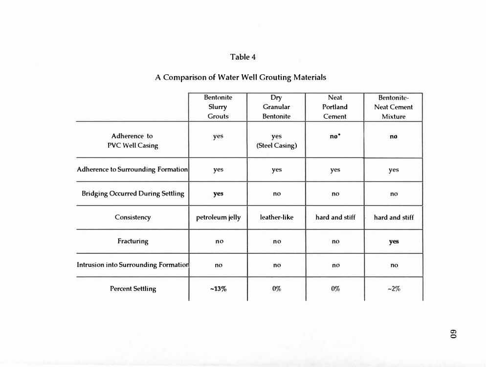
Table 4
A Comparison of Water Well Grouting Materials
Bentonite Dry Neat
Slurry Granular Portland
Grouts Bentonite Cement
Adherence to yes yes no*
PVC Well Casing (Steel Casing)
Adherence to Surrounding Formation yes yes yes
Bridging Occurred During Settling yes no no
Consistency petroleum jelly leather-like hard and stiff
Fracturing no no no
Intrusion into Surrounding Formatior no no no
Percent Settling ~13% 0% 0%
Bentonite-
Neat Cement
Mixture
no
yes
no
hard and stiff
yes
no
~2%
�
0

Table 4-continued
Bentonite Dry
Slurry Granular
Grouts Bentonite
Thickness Surrounding Well Casing ~2" <1/tr'-3/4"
Presence of a Filter Cake yes no
Cost moderate low
* Bold type indicates an area of special concern.
Neat
Portland
Cement
<l/tr'-6"
no
high
Bentonite-
Neat Cement
Mixture
<1/8"-6"
no
high
C') .,_.

62
Filter cake is an interesting sideline to this study. Filter cake was
found in the bentonite slurry wells, but not in the granular bentonite well,
nor in the cement wells. The presence of filter cake may provide an added
measure of contamination protection, especially in those wells in which
settling may be a problem. Although the· filter cake cannot prevent
contaminants from entering an open borehole from the surface, the low
permeability of the filter cake may help to slow or stop horizontal
migration of contaminants within the vadose zone or groundwater from
entering the borehole. The filter cake may be able to provide just enough
protection from contaminants until the well can be regrouted. Filter cake
however, should not be thought of as a grout replacement. It is not known
if filter cake can provide any protection whatsoever from contaminants. If
excessive settling does occur, more grout should be added as soon as
possible. Future studies should include the ability of filter cake to
withstand contaminants.
Another possible function of filter cake is to prevent the intrusion of
bentonite slurry grouts into surrounding formations. It would be
interesting to compare wells with filter cake versus wells without filter
cake in combination with settling problems and the role that intrusion
may play in the settling of grouts.

63 Fracturing of a grout can seriously jeopardize the integrity of the seal
of a water well. Fracturing was found in only one well, the bentonite
cement grouted well. This correlates with other studies.
Intrusion of grout into the surrounding formation did not occur at
shallow levels in the wells used in this study. All of these wells were
placed in medium sands, and a filter cake was present in the bentonite
slurry grouted wells. Perhaps in a gravel aquifer, or in a well in which no
filter cake is present, intrusion could occur.
From data collected in this field study, settling of approximately 13%
can be expected in wells sealed with bentonite slurries. The cement grouts
settled very little to none. The granular bentonite used to seal the cable
tool well did not settle.
Efforts to determine the total depth of settling for the bentonite
slurry grouts were unsuccessful. The soil probe could not penetrate the
hard pan created by the driving of protective casings down around the
wells. The gamma ray logs did not provide any conclusive results for this
study. A number of factors could have played a part in the apparent lack of
information gained from gamma ray logging the wells in this study.
All of the grouts varied in the thickness surrounding the well
casing, except for the bentonite slurry grout found in BH-396. In the
cement wells, thickness varied from less than 0.125 inch to almost 6 inches.
In the caple tool well grout thickness varied from less than 0.125 inch to
64 0.75 inch. Varying thickness of a grout surrounding a well may or may no t
affect the integrity of a we]] seal.
This field study cannot begin to cover an questions concerning
grouts, and should be used as a precursor to further studies. Tremendous
amounts of testing and product development ·remain to be conducted.
CONCLUSIONS
Stricter well installation codes have been developed because of
concerns about our groundwater resources, Improperly installed or
grouted water wells can be potentially dangerous to groundwater quality.
They can become direct pathways for the downward migration of
contaminants to groundwater.
This study has focused on water well grouting issues. It summarizes
previously published studies, and gives data concerning several properties
of grout evaluated in a field study conducted on Western Michigan
University Campus.
Various forms of bentonite, drill cuttings, drilling mud, neat
cement, and bentonite-cement and have all been used to seal water wells
with varying degrees of success. Each grouting medium has limitations;
however, each has its purpose and place in the water well industry.
Bentonite comes in many forms; powdered, granulated, chips or
tablets, etc. In the water well industry it is used for drilling mud and
grouting purposes. In use as a grout, bentonite has the capability of
providing the best water well seal available at this time. Its swelling
properties, its low permeability, its ability to adhere to well casings and
65

66
surrounding formations, and its ability to rehydrate, all add to the integrity
of a water we]I sea] made by a bentonite grout.
With all of the good qua]ities come limitations and many
unanswered questions about bentonite. Bentonite slurry grouts tend to
settle excessive]y and there are many questions concerning its ability to
withstand the forces of moving water, and its ability to maintain its
integrity over a long period of time.
Granulated bentonite when used to seal a cable tool well appears to
provide a very good seal, but it is uncertain how deep that seal actually
extends. Calculations have been developed to help answer this question;
however, these calculations are not physical evidence. Another area of
concern surrounding grouting cable tool wells is the mixing of the
surrounding formation with the granulated bentonite. This is not
considered to be a serious problem because the areas of mixing found
during the excavation were small, and it is thought that when the
bentonite is hydrated and swells the mixture of bentonite and the
surrounding formation will provide an adequate seal.
No standard method of application has been developed to effectively
apply chips or tablets as a grout, and they have been banned from use in
Michigan as a result. This form of bentonite has the capability of providing
the highest solids content, thus the best seal, however it tends to bridge,
leaving voids and gaps.
67
The use of drill cuttings and/ or drilling muds have been shown, for
the most part, to be unreliable grouting agents. Drill cuttings when
shoveled into the annular space between the well casing and the borehole
wall have the tendency to bridge, and may not satisfy the permeability
requirement of a grout. Drilling muds usually only contain 3 to 9% solids,
meaning that over 90% is water. Because of the low soJids content, drilling
muds settle excessively, tend to crack, and allow tracer dyes to pass through
them.
Cement grouts have been available for quite some time and have
been successfulJy utilized in the oil and gas industry. There seems to be a
lack of transfer in technology between the oil and gas industry and the
water well industry. Perhaps this is because of problems encountered
when using cement grouts for grouting water wells. Cement grouts have
been shown to raise the pH of nearby groundwater, form a micro-annulus
around PVC well casings, and may require additional equipment for
mixing and installation.
The addition of bentonite to cement was thought to solve the micro
annulus problem and any settling concerns. It has been shown in this
study as well as others that the addition of 5% bentonite increases the
likelihood of fracturing to occur. This is most likely due to the chemical
reaction that takes place between cement and bentonite.

68
The fie]d study conducted on Western Michigan University campus
focused on severa] properties of commonly used grouting mediums
thought to affect a water well's seal integrity. These properties were
adherence, bridging, consistency, filter cake, fracturing, intrusion, settling,
and thickness. Table 4 summarizes the data collected for the various grout
types.
Each grouting medium, mentioned in this study, was found to be
lacking in some aspect of providing an adequate well seal. The Jack of
adherence in the cement wells is a major concern. Fracturing, found in the
bentonite-cement grout, seriously jeopardizes the integrity of a well.
Settling of bentonite slurry grouts leaves an open borehole for the possible
migration of contaminants to occur. The best performing grout evaluated
in the field study was the granular bentonite used to sea] the cable tool
well. However, this well was installed by an atypical driller, who
developed the grouting method used to install the well for this study.
Therefore, the results seen in this study may be skewed. Questions sti11
exist about the ability to provide a seal along the entire length of a cable
tool well.
Recommendations
Groundwater resources will continue to be compromised if research
efforts are not promoted and supported. A very important aspect of this

69
study is to provide direction for future studies. Suggestions for future
studies are as follows:
1. Each grout property discussed earlier in this paper could be a
research project in and of itself. Detailed, well controlled studies of each
property could provide a tremendous amount of information, could help
to explain the deficiencies found in grouting materials and how to remedy
those deficiencies. Both laboratory and field studies are needed.
2. A better understanding of why and how bentonite slurry grouts
settle is essentiaJ. Settling studies should also address the role that filter
cake plays in this process.
3. Grout integrity below the water table needs to be investigated
more thoroughly.
4. DetaiJed studies of how to prevent a micro-annulus from forming
in cement grouts could provide a solution to this problem.
5. Grouting information and techniques from the oiJ and gas
industry should be collected and related to the water well industry.
6. A way to trace and detect all grouting materials through the well
casing should be developed. Perhaps a grout additive would work in
connection with a geophysical method. One possible additive is an
innocuous substance, such as shale, that produces a significant kick on the
gamma ray logger.

70
7. The development of a standardized method of application of
bentonite chips and tablets could produce the most effective grout yet.
8. Mixing cement with bentonite should be discouraged, if not
banned, unti] further investigations are performed.
9. Perhaps the most significant suggestion is the deve]opment of a
grouting performance standard. This standard would help raise the
awareness of inadequacies now found in grouting materials, and promote
further product development. This standard could be seen as a challenge
to the grouting industry to take on the task of making the changes needed
to protect ground water resources.
Regardless of who performs the research or produces a grout
performance standard, it is quite apparent that more in-depth and
conclusive research is needed in the area of water wel1 grouting. Proper
well grouting and grout integrity are important issues when considering
how to protect groundwater quality. A]] questions surrounding grouting
issues are important, yet there are no easy ways to answer them.

Appendix A
Lithologic Well Logs
71

Lithologic Well Log
Well Identification: BH-196 Date Drilled: 7-8-96 Location: Western Michigan University, Basement of Science Pavilion, Kalamazoo, Ml Drill Company: Raymer Co., Marne, Ml Driller: Rich Bloom and Craig Merlington Drilling Method: Mud Rotary Geologist: M. Kirby
Well Dia ram
Depth (ft) Description
8
18
38
48
53 58
68
73
78
83
88
93
98
103
108 113 123 133 138
C I . D omp etIon ata Depth (ft) Description
0-125' 8 - 50 lb bags of Wyo-Ben Groutwell OF bentonite tremmied to the surface lthrouah well annulus
0-130' blank 5" ID PVC riser pipe, 2.5' stick-up at surface 125-135' 6 - 50 lb baas of Flat Rock 20/40 filter sand 130-135' 5' of 20-slot 5" ID PVC screen with PVC bottom cap
G S r D rout ett Ino ata Elapsed Depth
Time (hrs) (ft) 1 1.83
10 10.83 15 10.83
Excavation Unknown
Additional Comments: 3' of collapse in hole, 135-138'.
72
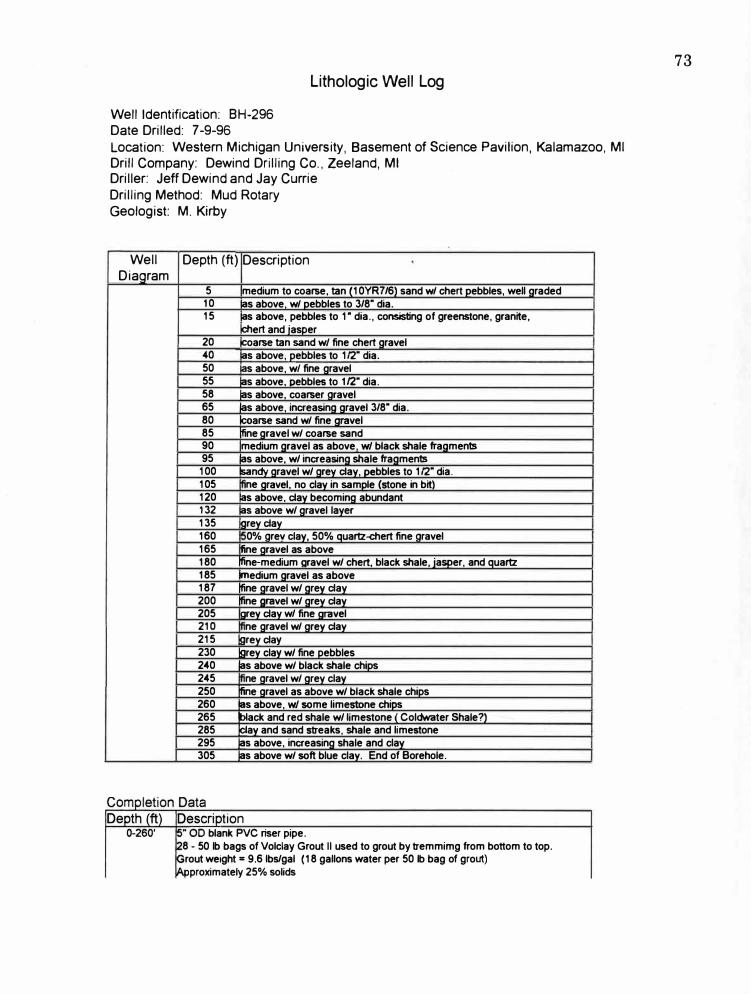
Lithologic Well Log
Well Identification: BH-296 Date Drilled: 7-9-96 Location: Western Michigan University, Basement of Science Pavilion, Kalamazoo, Ml Drill Company: Dewind Drilling Co., Zeeland, Ml Driller: Jeff Dewind and Jay Currie Drilling Method: Mud Rotary Geologist: M. Kirby
Well Diagram
Depth (ft) Description
5 medium to coarse, tan (10YR7/6) sand w/ chert pebbles, well araded 10 as above, w/ pebbles to 3/8" dia. 15 as above, pebbles to 1 " dia., consisting of greenstone, granite,
chert and iasoer 20 coarse tan sand w/ fine chert gravel 40 as above, pebbles to 112" dia. 50 as above, wl fine aravel 55 ias above, oebbles to 1/2" dia. 58 ias above, coarser aravel 65 ias above, increasing gravel 3/8" dia. 80 1coarse sand w/ fine gravel 85 !fine gravel w/ coarse sand 90 medium gravel as above, w/ black shale fragments 95 18s above, w/ increasing shale fragments
100 sandy gravel w/ grey clay, pebbles to 112" dia. 105 ne gravel, no clay in sample (stone in bit) 120 as above, clay becomina abundant 132 as above w/ aravel layer 135 orev clav 160 0% arev clay, 50% quartz-chert fine aravel 165 line gravel as above 180 fine-medium gravel w/ chert, black shale, jasper, and quartz 185 medium gravel as above 187 fine gravel w/ grev clay 200 nne gravel w/ arev clay 205 .1rey clay w/ fine aravel 210 ne gravel w/ arev clav 215 larev clav 230 larev clav w/ fine pebbles 240 18s above w/ black shale chips 245 ne gravel w/ grey clay 250 !fine gravel as above w/ black shale chips 260 ias above, w/ some limestone chips 265 black and red shale w/ limestone ( Coldwater Shale?) 285 �av and sand streaks, shale and limestone 295 ias above, increasina shale and clay 305 ias above w/ soft blue clav. End of Borehole.
tion "OD blank PVC riser pipe. 8 - 50 lb bags of Volclay Grout II used to grout by tremmimg from bottom to top. rout weight= 9.6 lbs/gal (18 gallons water per 50 lb bag of grout) proximately 25% solids
73

260-305' 145' of 4" OD 20-slot PVC screen.Each joint consisted of 6' slotted pipe at bottom and 3' of blank riser at top. 3x5 K-Packer installed at 260'.
G t S ttr D t rou e 1ng aa Elapsed Depth
Time (hrs) (ft) 0.42 2.25
2 4.42 11.5 21.25 14.5 25.5
Excavation Unknown
Additional Comments:
74

Lithologic Well Log
Well Identification: BH-396 Date Drilled: 7-10-96
Location: Western Michigan University, Basement of Science Pavilion, Kalamazoo, Ml Drill Company: Stearns Drilling, Dutton, Ml Driller: n/a Drilling Method: Mud Rotary
Geologist: M. Kirby
Well Depth (ft) Description Diaaram
5 fine gravel w/ coarse sand, pebbles of black shale, chert, quartz fine sand in sample
8 Qravel laver 10 same as 5', becoming coarser w/ chert, jasper, greenstone, limestone,
and quartz 15 fine gravel, as above 20 fine to medium gravel, as above, well graded, up to 3/8" dia. gravel 25 as above w/ jasper 30 as above w/ black shale chiP5 52 medium aravel as above w/ wood chios 57 !fine aravel, as above 72 fine to medium aravel, mostlv chert and ouartz w/ wood chios 77 larev clav wt wood, some aravel 82 !fine to coarse aravel, mOStlv chert, ouartz, and iasoer, no wood chips 84 laravel laver 89 medium to coarse aravel as above w/ wood. End of borehole.
Com letion Data De th ft Descri tion
0-83' 5" ID blank PVC riser pipe. 4' stick-up. 50 lb bags of Baroid Benseal bentonite w/ 1 gallon of Baroid EZ Mud Polymer.
rout tremmied from bottom of interval to top. Mix was 30 allons water er 50 lb ba bentonite and 12 oz. of EZ Mud
83-89' .38" 20-slot 5" ID PVC screen w/ 1.625' blank PVC riser pipe.
Grout Settlin Elapsed
Time hrs 14.5
Excavation
- 50 lb ba s of Flat Rock 20/40 filter sand.
Data Depth
ft 7.58 11
Additional Comments:
75
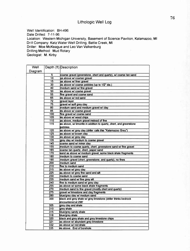
Lithologic Well Log
Well Identification: BH-496 Date Drilled: 7-11-96 Location: Western Michigan University, Basement of Science Pavilion, Kalamazoo, Ml Drill Company: Katz Water Well Drilling, Battle Creek, Ml Driller: Moe McKeague and Leo Van Valkenburg Drilling Method: Mud Rotary Geologist: M. Kirby
Well Depth (ft) Description Diagram
5 !coarse aravel (areenstone, chert and quartz), w/ coarse tan sand 10 las above w/ coarser gravel 15 las above w/ finer gravel 30 as above w/ coarse pebbles (up to 1/2" dia.) 40 medium sand w/ fine aravel 50 as above w/ coarse aravel 55 fine aravel and coarse sand 65 as above w/ red sand 72 gravel layer 75 gravel w/ soft grey clay 80 medium sand and medium aravel w/ clay 85 as above w/ coarse aravel
100 fine aravel w/ coarse sand 105 as above w/ wood chips 110 as above medium aravel instead of fine 115 las above, w/ limonite in addition to quartz, chert, and greenstone
bebbles 120 las above w/ grey clay (driller calls this "Kalamazoo Grey") 125 las above w/ brown clay 130 as above w/ arey clay 135 grey clay w/ medium to coarse aravel 145 coarse sand w/ minor clay 155 �edium to coarse auartz, chert, areenstone sand w/ fine aravel 165 coarse tan auartz, chert, iasoer sand 170 sand as above w/ medium aravel, some black shale fraaments 180 medium to coarse sand 190 medium aravel (chert, greenstone, and quartz), no fines 200 medium sand 210 fine to medium sand 215 as above w/ arey clay 225 as above w/ arey fine sand and silt 230 medium to coarse sand 235 medium sand w/ fine arey silt 240 fine to medium sand w/ grey clay 255 las above w/ some black shale fragments 270 medium sand to fine aravel (mostlv chert and quartz) 275 !gravel w/ limestone and clay fragments280 blue/grev clav w/ medium sand 300 black and grey shale w/ grey limestone (driller thinks bedrock
�ncountered at 298' 305 grey clay and shale 310 arey shale 315 blue/arey sandv shale 318 blue/grey shale 320 black and grey shale and grey limestone chips 321 as above w/ abundant grey limestone 332 as above w/ red shale 335 as above. End of borehole.
76

C I f D ompe 10n ata Depth (ft) Description
0-315' 5" ID PVC riser pipe. Pipe glued w/ PVC cement. 16" stabilizer installed at 1 0' below ground surface. 11-50 lb bags of Benseal bentonite and 7 lbs of catalyst.Grout tremmied from bottom of interval to top. Mix was 30 gallons water per 50 lb bag of bentonite. �x9 formation packer installed at 315'.
315-335' ooen hole
G t S I" D rou ett1ng ata Elapsed Depth
Time (hrs) (ft) 2.5 1 3.5 2.58
12.5 6.67 15.25 13.5
Excavation Unknown
Additional Comments:
77
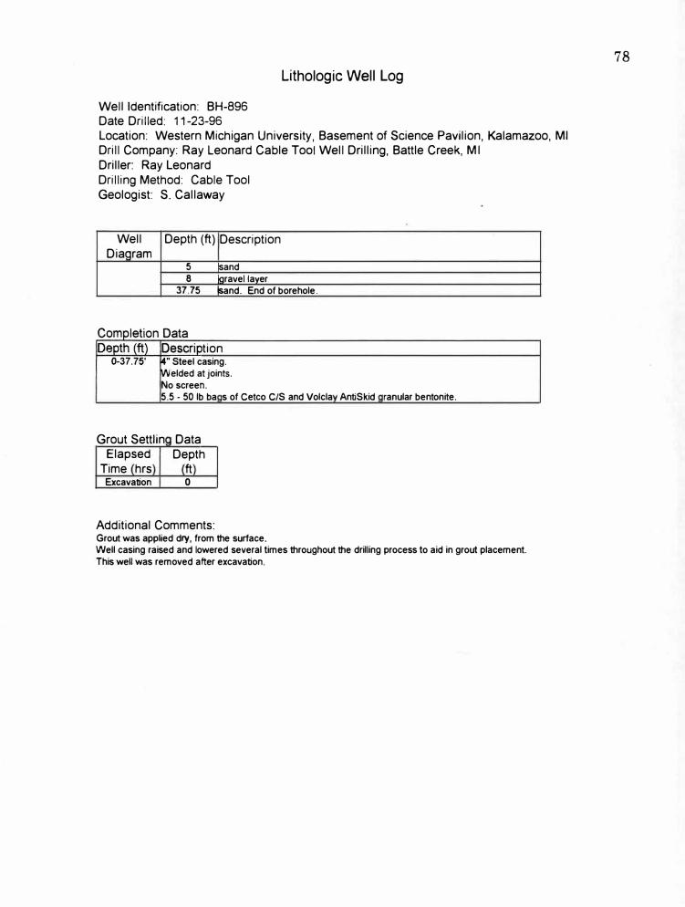
Lithologic Well Log
Well Identification: BH-896 Date Drilled: 11-23-96 Location: Western Michigan University, Basement of Science Pavilion, Kalamazoo, Ml Drill Company: Ray Leonard Cable Tool Well Drilling, Battle Creek, Ml Driller: Ray Leonard Drilling Method: Cable Tool Geologist: S. Callaway
Well Depth (ft) Description Diaqram
5 �and 8 laravel laver
37.75 lsand. End of borehole.
tion "Steel casing. elded at joints.
No screen. 5.5 - 50 lb ba s of Cetco C/S and Volcla AntiSkid ranular bentonite.
Grout Settlin Data Elapsed Depth
Time hrs ft Excavation 0
Additional Comments: Grout was applied dry, from the surface. Well casing raised and lowered several times throughout the drilling process to aid in grout placement. This well was removed after excavation.
78

Lithologic Well Log
Well Identification: BH-996 Date Drilled: 12-3-96 Location: Western Michigan University, Basement of Science Pavilion, Kalamazoo, Ml Drill Company: Katz Water Well Drilling, Battle Creek, Ml Driller: Moe McKeague Drilling Method: Mud Rotary Geologist: S. Callaway
Well Depth (ft) Description Diaoram
2 medium qrained, tan sand w/ small gravel 8 IQravel layer, medium sized, small amount of clay 9 medium qrained sand w/ small qravel
30.58 same as above. End of borehole.
C omp et,on D ata Depth (ft) Description
0-30.58' 5" PVC casing16 - 94 lb bags of Lafarge Type I Neat Portland cement, tremmied to to the surface. No screen. Mix was 5.6 aallons water oer 94 lb baa cement.
Grout Settlin Data Elapsed Depth
Time hrs ft Excavation 0
Additional Comments: A disposable tremie tube was used to grout this well. The tremie tube was cut off
at the surface and left in place. This well was removed after excavation.
79

Lithologic Well Log
Well Identification: BH-1096 Date Drilled: 12-3-96 Location: Western Michigan University, Basement of Science Pavilion, Kalamazoo, Ml Drill Company: Katz Water Well Drilling, Battle Creek, Ml Driller: Moe McKeague Drilling Method: Mud Rotary Geologist: S. Callaway
Well Depth (ft) Diagram
C I . D omp etIon
2 8 9
31.25
ata
Description
medium arained. tan sand w/ smaU aravel oravel laver, medium sized, small amount of clay medium orained sand w/ small oravel isame as above. End of borehole.
Depth (ft) Description 0-31.25' 5" PVC casing
5 - 94 lb bags of LaFarge and st. Mary's Type i Neat Portland cement, mixed w/ 1/2 bag PDS Co. Wyoming bentonite, tremmied to the surface.
No screen. Mix was 5.6 gallons water per 94 lb bag cement. Contained 5% bentonite.
Grout Settlin Data Elapsed Depth
Time hrs ft Excavation 0.5
Additional Comments: A disposable tremie tube was used to grout this well. The tremie tube was cut off
at the surface and left in place. This well was removed after excavation.
80

Appendix B
Percent Solids Calcu]ations
81

Percent Solids Calculations
Formula (Stichnan, 1990)
Total Weight Bentonite Used x 100
Total Weight Water Used+ Total Weight Bentonite Used
= Percent Solids
BH-296
Materials Used:
28 - 50 lb bags of bentonite
18 gallons of water per bag bentonite
Weight of Water = 8.33 lbs per gallon
Total Weight Bentonite Used
28 bags bentonite x 50 lbs
Total Weight Water Used
1400 lbs
18 gallons x 28 bags bentonite x 8.33 lbs per gallon
=4198.3 lbs
Percent Solids
1400 lbs
4198.3 lbs + 1400 lbs
BH-396
Materials Used:
X 100
4 - 50 lb bags bentonite
25%
30 gallons of water per bag bentonite
Total Weight Bentonite Used
4 bags x 50 lbs = 200 lbs
Total Weight Water Used
30 gallons x 4 bags bentonite x 8.33 lbs per gallon
=999.6 lbs
Percent Solids
200 lbs
99.6 lbs + 200 lbs
X 100 17%
82

BH-496
Materials Used:
11 - 50 lb bags bentonite
30 gallons water per bag bentonite
Total Weight Bentonite Used
11 bags x 50 lbs = 550 lbs
Total Weight Water Used
30 gallons x 11 bags bentonite x 8.33 lbs per gallon
2748.9 lbs
Percent Solids
550 lbs x 100 -------------
2748. 9 lbs + 550 lbs
17%
83
Appendix C
Excavation Well Logs
84
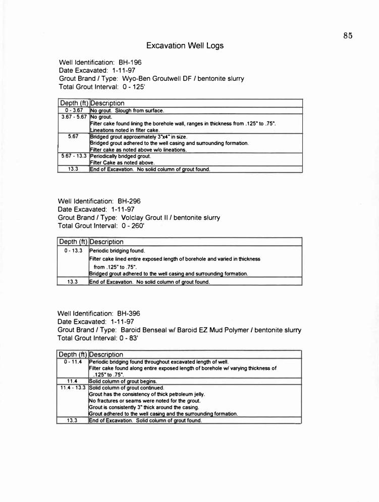
Excavation Well Logs
Well Identification: BH-196 Date Excavated: 1-11-97 Grout Brand / Type: Wyo-Ben Groutwell DF / bentonite slurry Total Grout Interval: 0 - 125'
Depth (ft) Description 0- 3.67 No grout. Slouah from surface.
3.67 - 5.67 No grout. Filter cake found lining the borehole wall, ranges in thickness from .125" to .75". Lineations noted in filter cake.
5.67 Bridged grout approximately 3"x4" in size. Bridged grout adhered to the well casing and surrounding formation. Filter cake as noted above w/o lineations.
5.67 - 13.3 Periodically bridged grout. Filter Cake as noted above.
13.3 End of Excavation. No solid column of arout found.
Well Identification: BH-296 Date Excavated: 1-11-97 Grout Brand / Type: Volclay Grout II / bentonite slurry Total Grout Interval: 0 - 260'
Depth (ft) Description 0 - 13.3 Periodic bridging found.
Filter cake lined entire exposed length of borehole and varied in thickness from .125" to .75".
Bridaed arout adhered to the well casino and surroundina formation. 13.3 End of Excavation. No solid column of grout found.
Well Identification: BH-396 Date Excavated: 1-11-97 Grout Brand / Type: Baroid Benseal w/ Baroid EZ Mud Polymer I bentonite slurry Total Grout Interval: O - 83'
Depth (ft) Descriotion 0 - 11.4 Periodic bridging found throughout excavated length of well.
Filter cake found along entire exposed length of borehole w/ varying thickness of .125" to .75".
11.4 Solid column of grout begins. 11.4 - 13.3 Solid column of grout continued.
!Grout has the consistency of thick petroleum jelly. No fractures or seams were noted for the grout. !Grout is consistently 3" thick around the casing. Grout adhered to the well casino and the surroundina formation.
13.3 End of Excavation. Solid column of grout found.
85
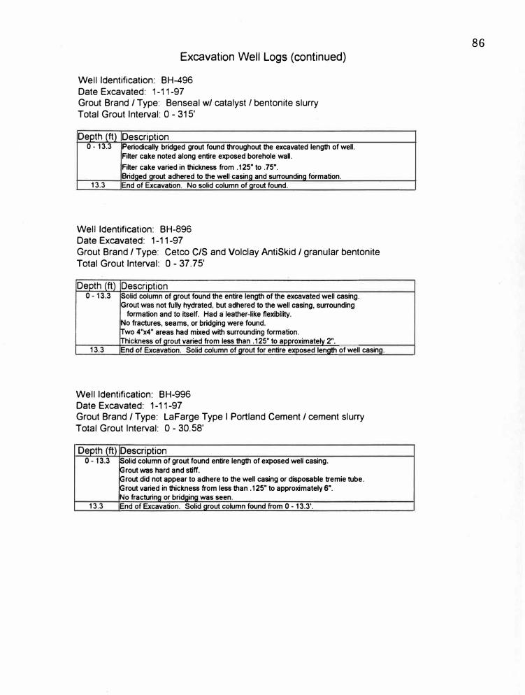
Excavation Well Logs (continued)
Well Identification: BH-496Date Excavated: 1-11-97Grout Brand/ Type: Benseal w/ catalyst I bentonite slurryTotal Grout Interval: 0 - 315'
Depth (ft) Description0 - 13.3 Periodically bridged grout found throughout the excavated length of well.
Filter cake noted along entire exposed borehole wall. Filter cake varied in thickness from .125" to .75". Bridaed arout adhered to the well casino and surrounding formation.
13.3 End of Excavation. No solid column of grout found.
Well Identification: BH-896Date Excavated: 1-11-97Grout Brand/ Type: Cetco C/S and Volclay AntiSkid/ granular bentoniteTotal Grout Interval: O - 37.75'
Well Identification: BH-996Date Excavated: 1-11-97
of well casin .
Grout Brand/ Type: LaFarge Type I Portland Cement/ cement slurryTotal Grout Interval: 0 - 30.58'
13.3
olid column of grout found entire length of exposed well casing. rout was hard and stiff. rout did not appear to adhere to the well casing or disposable tremie tube. rout varied in thickness from less than .125" to approximately 6".
No fracturin or brid in was seen.
86
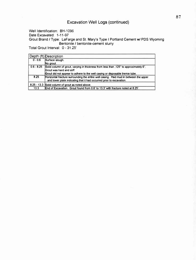
Excavation Well Logs (continued)
Well Identification: BH-1096 Date Excavated: 1-11-97 Grout Brand/ Type: Lafarge and St. Mary's Type I Portland Cement w/ PDS Wyoming
Bentonite / bentonite-cement slurry Total Grout Interval: O - 31.25'
Depth (ft) Description 0 - 0.6 Surface slough.
No arout. 0.6 - 8.25 Solid column of grout, varying in thickness from less than .125" to approximately 6".
Grout was hard and stiff. Grout did not appear to adhere to the well casing or disposable tremie tube.
8.25 Horizontal fracture svrrounding the entire well casing. Had mud in between the upper and lower plate indicating that it had occurred prior to excavation.
8.25 - 13.3 Solid column of arout as noted above. 13.3 End of Excavation. Grout found from 0.6' to 13.3' with fracture noted at 8.25'.
87
Appendix D
Settling Charts
88
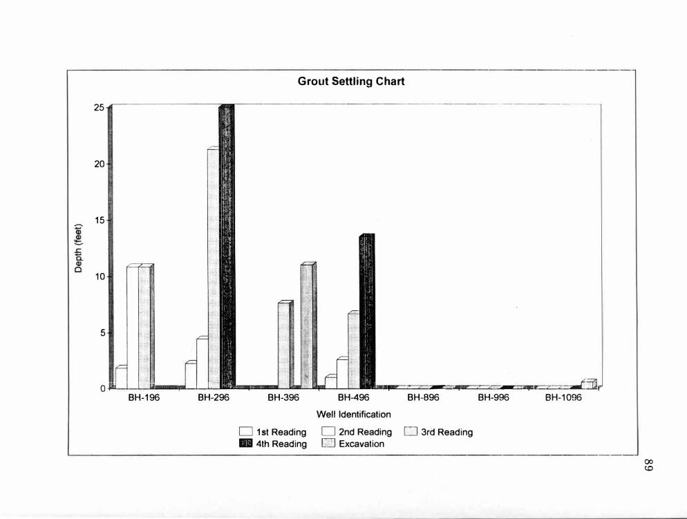
-
25
20
15
10
5
0 � I I t'il I al I I" BH-196 BH-296
Grout Settling Chart
BH-396
D 1st Reading • 4th Reading
he I z .-, .. , . ., ·-----., .•.• z z J�BH-496 BH-896
Well Identification
D 2nd Reading [ill] 3rd Reading CID:] Excavation
BH-996 BH-1096
CXl co
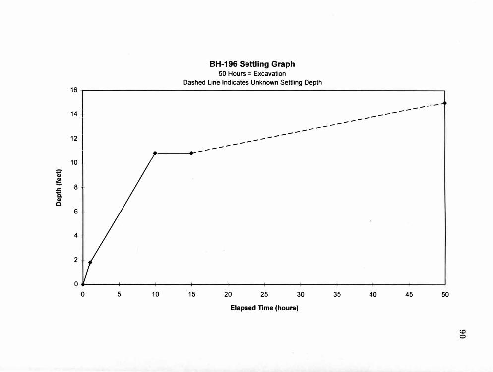
BH-196 Settling Graph50 Hours = Excavation
Dashed Line Indicates Unknown Settling Depth 16
--
--
14 -1- ------
--
--
------
--
12 I --
--
--
--
---
101 ,... -
-
G)
G)
8 --
G)
6
4
2 ·•·
0 0 5 10 15 20 25 30 35 40 45 50
Elapsed Time (hours)

-
Cl)
-
Cl)
BH-296 Settling Graph 50 Hours = Excavation
Dashed Line lndictes Unknown Settling Depth w
--------
--------
--------
--
-------
20
0 ..... -----+----+-----+----t-----+----+----+------+----+-----1
0 5 10 15 20 25 30 35 40 45 50
Elapsed Time (hours)
co 1--'

;:-, Cl)
Cl)
BH-396 Settling Graph 50 Hours = Excavation
12 ----------------------------------------.
6
o-----------------------------------------1
0 5 10 15 20 25 30 35 40 45 50
Elapsed Time (hours)
co t,,:)
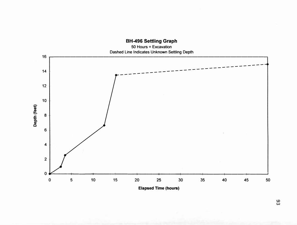
-
-
cu C
BH-496 Settling Graph 50 Hours = Excavation
Dashed Line Indicates Unknown Settling Depth 16 -----------------------------------------
14 �-
---------------------------------
12
4
0 .,_ __ --4-___ ......,.. ________ ......... ___ ,1..--__ ----1-___ 4--__ ---4-__________ ---I
0 5 10 15 20 25 30 35 40 45 50
Elapsed Time (hours)
c.o Cl,;)
Appendix E
Gamma Ray Logs
94
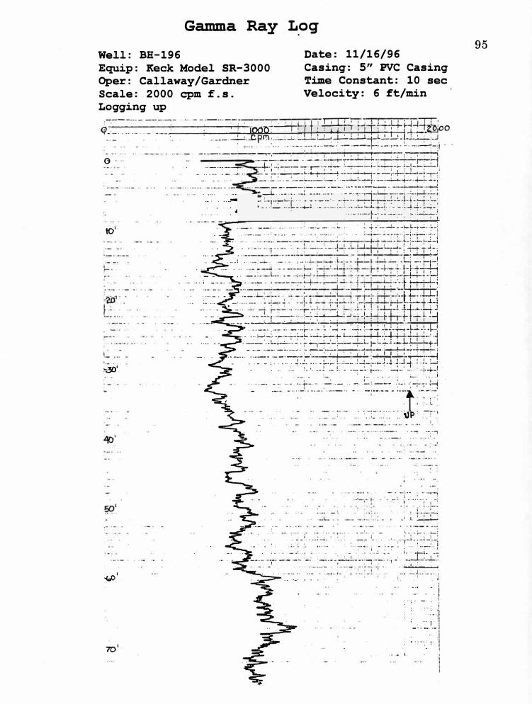
Gamma Ray L_og
Well: BB-196 Equip: Keck Model SR-3000 Oper: Callaway/Gardner Scale: 2000 cpm f.s. Logging up
Date: 11/16/96 Casing: 5" PVC Casing Time Constant: 10 sec Velocity: 6 ft/min
! ,-----------�- ·······--·--··--. . • • • ·11: ITJT· •... •J_•:, 'm· �----··---.---·-- -:---·--·r••"-•---,·�----n-�._ - I�-',- +1-1-; ·oo'(._··-·· ····-···- ____ ; ____ -·-- .:...-·-----�--i�- I �I I l+l �,i • ..__ I -· '
: ---...l...!._c.P-r!l::��"�:�=-=:��=+=-�:-�+�_ .. __ :,0 .
---- . !:�r;�;:==:to" ... _. __ ··-· ·-.-::.··•�. - ·--·-· -- ·--�- •·· :. � ->---�--� -�-�-+�---�-;
1 __ •••
!'.30'
�·
70'·
. -- _L_ r ··-� ... _, ..:....i--L! .J-:. -'-w+ +- _ 1_ ·-l
---:��BlllfJ#�--� •··-r-:··•· --··-... �- -�:
____ -:.-.- -;+ __ ·--:-_1-4 ___ :-····-··•··-·····--··• -··· -·---- - ··-1
J -·- - •••• - •• ' - : :--:-_ ··, · __ ;_ . . .. � :·-:·7
•••• -•• _1 -
·-•. --i"·-� -·--,-� ·• .... , -·, • I
-;
-:- ....... � .._, .i. t_!-� .. :
·r . -:-... -,--- --·-·. :--,-i-:---�-: . ··•-··--. .• •• . �:- ·--- �- • .J. -➔ • •,.. ... . ... ....... . .- : _
-__ :···f .... ·; .. .:I.7
�.! .. : . . . ·••. '.I •1 .•• '. � .' .i., • �- -�-
• . _ : ___ .. --; .. :. � :--�-: .. ; .. ··, _. :__!:£±:.:.t.. . :
•!
95

Gamma Ray Log
Well: BB-296 Date: Equip: Keck Model SR-3000 Oper: Callaway/Gardner
11/15/96 5" PVC Casing:
Time Velocity:
Casing Constant: 10 sec
/Montgomery Scale: 2000 cpm f.s. Logging up
6 ft/min
a.
. 10·1•
r··· ·-
�---·--··
�!.::.
:--.. --- .· ....
�.-'. :-·'-·· r· . '."'r -··· · .
ii/-I... •• •
l.' ..
1000 CptT').
�. ·-•-•><• . ····- ... . - ---·- -----,--� _,_...,. ___ ,
·-·--' ' . : r·· ·-:
._.:·.::: ·· ::.·:� � �-· :·:·.-.� ·:-i :: � i+ ·::.:±(��) ff 1J
. - -- ---·-· ----- -----
:. '! ..
-�-----•-
··'"'•-'•· ;" . ,-.I�-;--
. .
··-···--'····---·--·•··-·�- .. -· : __ - •.... �- __ : __ .. _: __ 1 .•. ____ j__ __________ ., --· _ _. ____ . ---··• - . _;._. ____ ._ -- -·----�------· ----------···. :--�
• • • I ·-- ------- ----·--·-·. --- ··---·------•.. ·-· ._.. ____ , ___ �-- .. - ·•··•··· ···-··. ··----.. -·····•··-·-· ••- I•-----•-•••--•••-�-�--• •
······-··· .--··-·····-•• - ,-·
----,· - __ , ___ •• j ···-· •• 1 •. -: ;�) ·- ... _ ' --------------------- ' -----� ---·--. --: , ____________ --·· . ; .-·•-r-,-:·-- ... •··•-··•·•---···----· ------·-·-·--·-. •--.· -··
-�
:.· ·=--::�·-���j���.?=t:����-��18 '
··• : .... _, ··-··:. � ��-:�;• I--•- -- ... •• ,• -•••• ·--• • -••··- ..... ----· ··--· ..... ·•··•---... , ··•-·-··-•-.-··· - ·· ·--- --·. -··. ' ......... ; . . . . .
• .... --- . 1_ ; _�,
--- ·---·--,·-·· ··--------·.-·---·- ; •. : -:- •. i ·-- -· ·------.;- ·. _____ ; __ . ... . : .... ·.. ,_ .... ···- -�--·- ' ... - . - -· -·- . . ---·
.l.. •.... 7�-.. J-4_; • • • I • ··-- ---- ....... -- .. -
·····-, -·
96
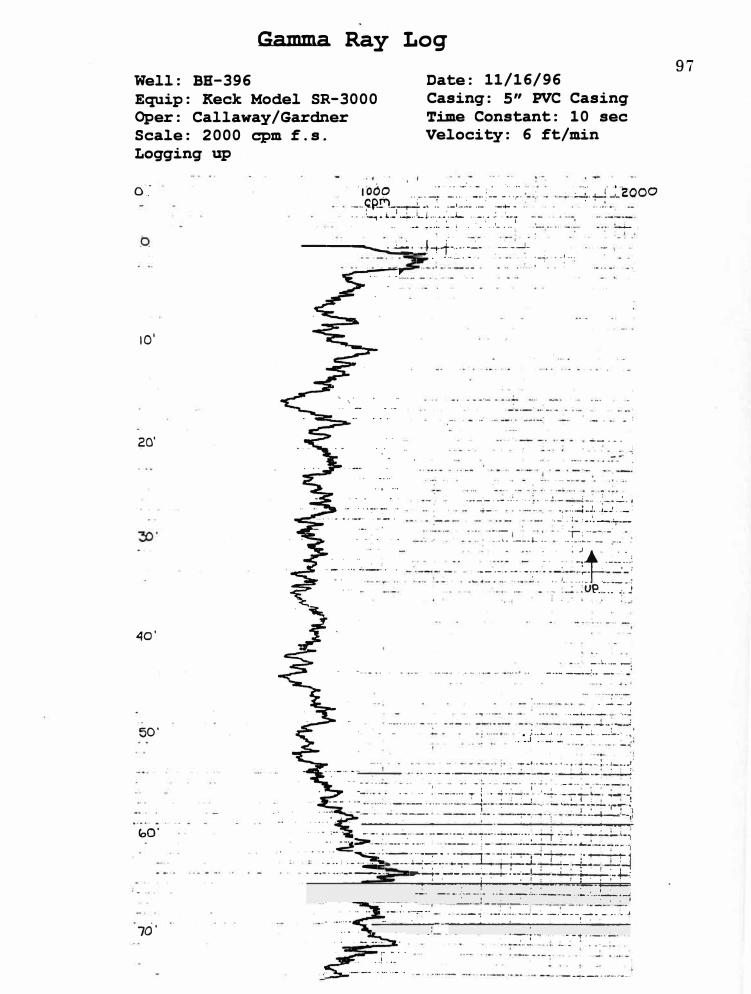
Well: BH-396
Gamma Ray Log
Date: 11/16/96
Equip: Keck Model SR-3000 Oper: Callaway/Gardner Scale: 2000 cpm f.s. Logging up
Casing: 5" PVC Casing Time Constant: 10 sec Velocity: 6 ft/min
er.·
10'
20'
40'
50'
<oO'
70'
·-' _,_
----..... ·:=.;·_j·f ?::t.:..·:��--·--· _ __J_
-�- •• 1. ••.
..:..._ •,-.
···--·-""!'·······.· ··'·- . ·-·•• ·:-·•_:·,+-· ..
.,_: _ j_ : ... ;•--;---... ;..,_;_ ·r, ··--.··-·
·-·•l• •--•'• •• ·- ·---�- - -·· -
� .. . '. _;� .. .:-�.�.:·-----·•--·-· -··-· , ___ ; __ ..... �·r. ..... �� ... ;
:!JP., ... ,.�
_.i .. ,_ �
·---- --·-\· __ .,. ..
. ---- J
----�-----••,• -••• i
; __ ..._ ., . • :. � _i, -!.
.--�-- '.,
'! --i-----�-- '·-, .. -- -- �--,-1.----�·,._, _______ .., _______ . ---- + -·: ... -� '-�-�
- .. - j"'•• .. ------·--·----·--,
-·---�--�--�-�-:-·--··• �-·--__ :·--��-- :-�-_--:::}:�i}··--•�••:::�i;ji}����
- -- ·--.'
-:-
-�: __ · .···-.:. •-C··:· •·-�-� �.:=��:.-:.:::.�·:�-�!
·•·�·;··. ··--t· -··· .... ..... - . - . ----
-• --""'!--d•"'•-"'--•
97
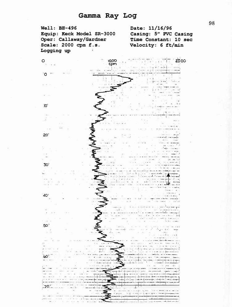
Gamma Ray Log
Well: BB-496 Date: 11/16/96 Equip: Keck Model SR-3000 Oper: Callaway/Gardner Scale: 2000 cpm f.s. Logging up
Casing: 5" PVC Casing Constant: 10 sec Time
Velocity: 6 ft/min
0
·o
10'
20'
.'30 '
-40'
EO.'
;,- .
10.00 cprn
I ' - ·�-!-- .. ·
r···. -� ·•.
. ; - � ..
• I
. - ·- -·· ••' - I •--;, •• • •
�--
•.. ,.J. .. ,. --� . '
- j" -;
�00
..... :·�l------'.
. ---� -·-·- _. __ j
---,· ·-�
:; .. :-•·-'
. 1 ·: -�--i
... -,- .
__ :_ ..
.. ---·--� ,: . .--·--•---l-,
-��- __ ._ ___ .
:·-'·· <. ;-' -� .: •···--······•·- -··-·-···· 1 __ ---: .·
·- - � .... ·•··i .... .,; . .. ·--
• .• 1 -
.. : __ --- -�-�--··- -----·, ......... •·•••·· ·•- l.
--, - -·• .. - -.. -- --- -- -� ·-.-I'--! ... --- ·, .. '-------- ..' . . ····----- -· - ----·
1 ______ �_ ' . . '
... . ' . ' .. �--· -� -�-! __ ; .. :-·• --
' ' . . .. ,_,._,, ...•. ---·---' •· ·.·--- -• • : I
_ ...... -"!' .. __ ... i_ ... :-���S:y#;�=$·:";���� ·, .... •::-(
_;�.--I •. _•:.' : : _ · 1 --•· -· : _-.- .: .. '
' . . :,_:_ .' ·• � ----�- -- .... ..:. �-��- . ...l. _:__:. __ � •• :
98
BIBLIOGRAPHY
American Colloid Co., 1997, ACCTour: Online, Available: http://www.colloid.com.
Barcelona, M.J., Gibb, J.P., Miller, R.A., 1983, A Guide to the Selection of Materials for Monitoring Well Construction and Ground-Water Sampling: Illinois State Water Survey, SWS Contract Report 327,
p.48.
Bates, R.L., Jackson, J.A., 1984, Dictionary of Geological Terms Third Edition: Bantam Doubleday Dell Publishing Group, Inc.
Bentonite Corporation, 1997, Bentonite Industry: Online, Available: http://www.tcd.net/ ~wma/bent/benthome.html.
Bertane, M., 1987, Grout Report, The Use of Grout for the Sealing of Monitoring Wells: American Colloid Company.
Bucher, L., 1993, Bentonite Slurry Grout in the Vadose Zone: An Effective Seal? (Part 1): National Drillers Buyers Guide, March, p. 14.
Bucher, L., 1993, Bentonite Slurry Grout in the Vadose Zone: An Effective Seal? (Part 2): National Drillers Buyers Guide, April, p. 40.
Callaway, S.L., 1997, Field Notes and Photographs.
Department of Army and Air Force, 1975, Well Construction Operations: Code: FM-166/ AFR85-23.
Dresser Atlas, 1982, Well Logging and Interpretation Techniques: Dresser Industries Inc., p. 84-88.
Driscoll, F.G., 1986, Groundwater and Wells: Johnson Filtration Systems Inc., p. 268-277.
99
Dumouche11e, D.H., Lynch, E.A., Cummings, T.R., 1990, A Literature Survey of Information on Well Installation and Sample Collection Procedures Used in Investigations of Ground-Water Contamination by Organic Compounds: United States Geological Survey, Open-File Report 90-378, p. 20.
Dunnivant, F.M., Porro, I., Bishop, C., Hubbell, J., Giles, J.R., Newman; M.E., 1997, Verifying the Integrity of Annular and Back-Filled Sealsfor Vadose-Zone Monitoring Wells: Ground Water, Vol. 35, No. 1, p.140-148.
Edil, T.B., Benson, C.H., 1995, Evaluation of Well Seals Using an Ultrasonic Probe: Research Funding Request, University of Wisconsin.
Edil, T.B., Chang, M.M.K., Lan, L.T., Riewe, T.V., 1992, Sealing Characteristics of Selected Grouts For Water Wells: Ground Water, Vol. 30, No. 3, p. 351-361.
Gaber, M.S., 19%, Public Letter: Michigan Department of Public Health, February.
Gaber, M.S., 1997, Personal Communication: Michigan Department of Environmental Qua1ity, Water Well Division, September.
Grim, R.E., 1941, The Oay Minerals in Soil and Their Significance: Illinois State Geological Survey Circular, No. 65, p. 9-12.
Grim, R.E., 1953, Clay Mineralogy: McGraw-Hill Book Company, Inc.
Ground-Water Survey TNO, 1976, Geophysical Well Logging For Geohydrological Purposes in Unconsolidated Formations: Netherlands Organization for Applied Scientific Research (TNO), p. 42.
Kirby, M., 19%, Well Logs: Personal Communication.
Kurt, C.E., 1979, Collapse Pressure of Thermoplastic Water Well Casings: Ground Water, Vol. 17, No. 6, p. 550-556.
Kwader, T., 1986, Methods of Detecting Grout Behind Casings: National Drillers Buyers Guide, June, p. 15.
100

Leonard, R., 1985, Dry Grout Driven Method: New Approach to Grouting: Ground Water Age, March, p. 19-23.
Lio, A., 19%, Industrial Drilling Products Field ServiceReport - FS-005: Baroid Drilling Fluids, Inc., p. 1-10.
McLarty, F.R., 1993, Grouting Materials: National Drillers Buyers Guide, June, p. 29.
Michigan Department of Public Health Ground Water Quality Control Section, 1988, Michigan Water Well Grouting Manual: State of Michigan.
Michigan Department of Public Health Ground Water Quality Control, 1994, Michigan Water Well Construction and Pump installation Code: State of Michigan, Part 127-Act 368.
Ogden, F.L., and Ruff, J.F., 1991, Setting Time Effects on Bentonite WaterWell Annulus Seals: Journal of Irrigation and Drainage Engineering, Vol. 117, No. 4, p. 534-545.
Ogden, F.L., and Ruff, J.F., 1993, Strength of Bentonite Water-Well Annulus Seals in Confined Aquifers: Journal of Irrigation and Drainage Engineering, Vol. 119, No. 2, p. 242-250.
Oliver, R., 1991, Grouting: High Solids Bentonite Grout vs. Cement Grout: National Drillers Buyers Guide, April, p. 41.
Oliver, R., 1995, A Driller's Challenge: Achieving An Effective Grout Seal in the 90's: National Drillers Buyers Guide, November, p. 12-13.
Oliver, R., 1997, Bentonite Grouts vs. Cement Grouts: National Drillers Buyers Guide, May, p. 37.
Papp, J., 1994, Bentonite Sealants: National Drillers Buyers Guide, March, p. 28.
Portland Cement Association, 1965, Concrete Technology: Delmar Publishers, New York, p. 17-23.
Riewe, T., 19%, Can Drilling Mud and Cuttings Slurry Be Used as Grout?: Water Well Journal, February, p. 29-35.
101
The Roscoe Moss Company, 1990, Handbook of Ground Water Development: John Riley & Sons, p. 131-134.
Smith, D.K., 1976, Cementing: Society of Petroleum Engineers of AIME.
Smith, S., Mason, C., 1995, Bentonite Grouting: Water Well Journal, February, p. 35-37.
Stichman, R.W., 1990, Sealing Borehole With ·sodium Bentonite: Iowa Groundwater Association Newsletter,Vol. 2, No. 11, September, p. 1-11.
Telford, W.M., Geldart, L.P., Sheriff, R.E., Keys, D.A., 1976, Applied Geophysics: Cambridge University Press, p. 773.
Velde, B., 1992, Introduction to Clay Minerals: Chapman and Hall, London, p. 1-10.
102