a control-oriented reaction-based si engine combustion model articles/a control-oriented...the model...
TRANSCRIPT
A CONTROL-ORIENTED REACTION-BASED SI ENGINE COMBUSTION MODEL
Ruixue C. LiEnergy and Automotive Research Laboratory
Department of Mechanical EngineeringMichigan State University
East Lansing, Michigan 48824Email: [email protected]
Guoming G. Zhu∗Energy and Automotive Research Laboratory
Department of Mechanical EngineeringMichigan State University
East Lansing, Michigan 48824Email: [email protected]
ABSTRACTThis paper proposes a control-oriented chemical reaction-
based two-zone combustion model designed to accurately de-scribe the combustion process and thermal performance forspark-ignition engines. The combustion chamber is assumed tobe divided into two zones: reaction and unburned zones, wherethe chemical reaction takes place in the reaction zone and theunburned zone contains all the unburned mixture. In contrast tothe empirical pre-determined Wiebe-function-based combustionmodel, an ideal two-step chemical reaction mechanism is usedto reliably model the detailed combustion process such as mass-fraction-burned (MFB) and rate of heat release. The interactionbetween two zones includes mass and heat transfer at the zoneinterface to have a smooth combustion process. This control-oriented model is extensively calibrated based on the experimen-tal data to demonstrate its capability of predicting the combustionprocess and thermodynamic states of the in-cylinder mixture.
NOMENCLATUREMFB Mass fraction burned.HRR Heat release rate.IVC Intake valve closing.EVO Exhaust valve opening.RGB Residual burned gas
∗Correspondence author.
INTRODUCTION
The continuously strict emission regulations and diminish-ing petroleum reserve lead to increased demand for high-efficientand low emission internal combustion engines [1]. And off-lineand on-line simulation models are extensively used in the pastdecades due to the advantages of reducing engine developmentduration and cost and improving real-time operational perfor-mance. As part of model-based engine control, major progresshas been made in the development of the control-oriented engineand combustion models for both spark-ignition (SI) and dieselinternal combustion engines.
Up to now, a variety of engine models are availablefor engine performance prediction, model-based design, andcontrol, etc. And these models can be classified as multi-dimensional, zero- and one-dimensional (0-D/1-D), quasi-dimensional two/multi-zone, and zero-dimensional models [2].The multi-dimensional models are extensively used in computa-tional fluid dynamics(CFD) analysis to simulate the detailed cy-cle process in the cylinder with high accuracy. One of the mostpopular ones is the CHEMKIN-CFD module for ANSYS FLU-ENT that uses the multi-dimensional model to simulate detailedchemical mechanisms and chemically reacting flows in a multi-dimensional cylinder and to trace individual species information.However, since these models involve thousands of reactions andhundreds of species, it requires significant computational power,which limits its application to model-based control due to thereal-time requirement. 0-D/1-D models, such as GT-Power andRicardo Wave models, have reduced complexity and run muchfaster, comparing with multi-dimensional models. Some pro-
Proceedings of the ASME 2018Dynamic Systems and Control Conference
DSCC2018September 30-October 3, 2018, Atlanta, Georgia, USA
DSCC2018-8988
1 Copyright © 2018 ASME
Dow
nloaded from https://asm
edigitalcollection.asme.org/D
SCC
/proceedings-pdf/DSC
C2018/51906/V002T27A002/2376913/v002t27a002-dscc2018-8988.pdf by M
ichigan State University user on 04 Septem
ber 2019

cesses such as combustion, heat and mass transfer in these mod-els are simplified by using 0-D (and some are 1-D) assumption.With the significantly reduced computational, the fluid proper-ties and detailed engine performance can be simulated. However,the model is still not simple enough to be used for model-basedcontrol. The zero-dimensional model [3] is the least complexand the gas dynamics and combustion processes are simplifiedby using empirical coefficients and maps to reduce simulationtime. The control-oriented mean-value one-zone model [4] is atypical example of the zero-dimensional model, where numerousexperiment-based maps and coefficients are used, making it verysensitive to engine operating conditions and operational environ-ment. Furthermore, it is not able to predict in-cylinder pressure,heat release rate (HRR), and reaction kinetics so that it cannotbe used for model-based combustion control. To overcome thelimitation of one-zone model, the two-zone [5] and multi-zonemodel [6–8] are proposed. In the two-zone model, the unburnedand burned mixtures are separated by assuming that the flamefront is a thin boundary layer while the multi-zone model dividesthe gas mixture in more detail. Due to the real-time simulationcapability of predicting important engine process, the two-zonemodel is widely used as a control-oriented model in these years.
Many two-zone combustion models [9–11] are published inliterature these years. However, the mass-fraction-burned (MFB)rate for all these models is determined by a pre-defined empiri-cal Wiebe function that needs to be calibrated for every engineoperating condition based on experimental data. This makesit, sometimes, impossible to obtain a good calibration for theWiebe-based combustion model. Moreover, the experimentaldata are unavailable for the study of some engine performances,such as for exploring wide ranges of new engine concepts (pres-sure charging, inter-cooling, variable valve timing, EGR, etc.) [3]which are too complex to be predicted using a predefined Weibefunction. This indicates that the MFB rate must be modeledinstead of using the pre-defined curve. Note that the proposedreaction-based combustion model is able to predict the real-timerate of MFB and in-cylinder pressure by taking the chemical ki-netics into account recently.
Jia and Wang [12] developed a control-oriented reaction-based single-zone combustion model for a propane-fueled Ho-mogeneous Charge Compression Ignition (HCCI) engine, Menand Zhu [13, 14] also proposed a control-oriented three-zonereaction-based combustion model for direct-injection (DI) dieselengines. Both models discarded the empirical pre-defined Wiebemodel for the rate of MFB but adopted two-step chemical ki-netic mechanism in conjunction with the Arrhenius Function.For the reaction process, the one-step reaction mechanism is notable to describe the flame propagation from lean to rich combus-tion [15]. Its main weakness is the neglecting of CO producedin the combustion process as the CO oxidation is a rather slowprocess [15, 16] and large amount of CO and H2 exists in theequilibrium with CO2 and H2O. While the multi-step chemi-
cal mechanism will increase the computational time. Therefore,the two-step chemical mechanism is good for the reaction-basedcombustion model.
This paper focuses on the development and validation ofa control-oriented reaction-based combustion model for SI en-gines, where two-zone modeling structure is used, along with thetwo-step chemical reaction mechanism, and the rates of chemicalreactions are based on the Arrhenius function for the in-cylinderthermodynamic and combustion process. The model is validatedagainst experimental data and the simulation results are used todemonstrate its capability of predicting the combustion process.
The main contribution of this paper is that the proposedtwo-zone two-step chemical reaction model is able to predictthe mass-fraction-burned, heat release rate, in-cylinder pressurealong with thermodynamic properties of individual species suchas their chemical reaction rate, associated molar concentration,and concentration variation, etc.
This paper is organized as follows. The outline of this pro-posed model is discussed by addressing the mass and heat trans-fer interaction on the boundary layer of the two zones and thechemical reaction rates of individual species based on the Arrhe-nius function, along with thermodynamic states and propertiesin two zones. The model’s capability of predicting combustionprocess and mixture thermodynamic properties is demonstratedagainst experimental data. At last, the conclusions are drawn.
MODEL DESCRIPTIONThe proposed model focuses on the in-cylinder dynamic
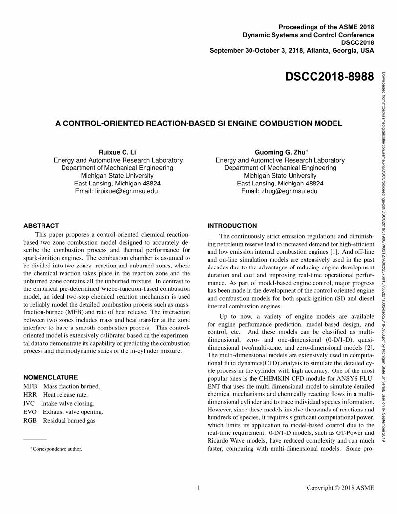
process between Intake Vale Closing (IVC) and Exhaust ValueOpening (EVO). It is assumed that the fresh air and fuel are pre-mixed before IVC and the total mass in-cylinder from IVC toEVO includes the pre-mixed fuel and air; and also the residualgas trapped in the cylinder from the last cycle. A two-zone mod-eling structure shown in Fig.1 is applied to predict the in-cylinderprocess in this paper. It is also assumed that the mixture in thecombustion chamber is divided into two zones, where the un-burned zone contains the unburned mixture, and the chemical re-action process and associated products are in the reaction zone.It is also assumed that the mixture in two zones are homogeneousand the in-cylinder pressure maintains equilibrium between twozones.
The reaction zone starts with a very small amount (say 1.5%)of the unburned mixture at IVC, while over 98% of total un-burned mass is assigned to the unburned zone. There is no in-teraction between two zones until the spark ignition. When thecombustion is initiated and flame propagates, the unburned mix-ture is transferred to the reaction zone and burned at the sametime. The chemical reaction products and residual oxygen stayin the reaction zone. The two zones interact through mass andheat transfer at the boundary. Furthermore, it is assumed that thereaction zone, in a sphere shape, has no contact area directly with
2 Copyright © 2018 ASME
Dow
nloaded from https://asm
edigitalcollection.asme.org/D
SCC
/proceedings-pdf/DSC
C2018/51906/V002T27A002/2376913/v002t27a002-dscc2018-8988.pdf by M
ichigan State University user on 04 Septem
ber 2019
Spark Plug
Reaction Zone
Unburned Zone
FIGURE 1. TWO ZONE MODEL STRUCTURE-BASED COM-BUSTION MODEL.
the cylinder wall, while the unburned zone is fully contacted withthe cylinder boundary, where the heat loss takes place.
MODELING METHODSZone Volume
The total in-cylinder volume Vcyl and its rate of change Vcylcan be obtained from the piston motion law [17] below.
Vcyl =Vc
(1+
rc−12
[R+1− cosθ −
√R2− sin2
θ
])(1a)
dVcyl
dt=
(rc−1)Vc
2sinθ
(1+
cosθ√R2− sin2
θ
)dθ
dt(1b)
where θ is the crank angle; rc is the compression ratio; R is theratio of connecting rod length to crank radius; and Vc is the clear-ance volume. Therefore, by assuming the mixture in unburnedand reaction zones are homogeneous, the unburned zone volumeVu can be calculated first based on the ideal gas law and the vol-ume rate Vu can be derived from Vu.
Vu =muRuTu
pMWu(2a)
Vu =dVu
dt(2b)
where mu, Tu and MWu are mass, temperature and molecularweight of the unburned zone, respectively. Since there is nochemical reaction occurs in the unburned zone, the species com-position in this zone remains unchanged. Therefore, the molecu-lar weight MWu can be calculated based on the data at IVC.
MWu =mu,0RuTIVC
pIVCVIVC(3)
where mu,0 is the initial mass in the unburned zone. The volumeand its rate of change(Vr and Vr) in the reaction zone can be ob-tained based on the conservation equation shown in Eqns. (4a)and (4b).
Vr =Vcyl−Vu (4a)
Vr = Vcyl−Vu (4b)
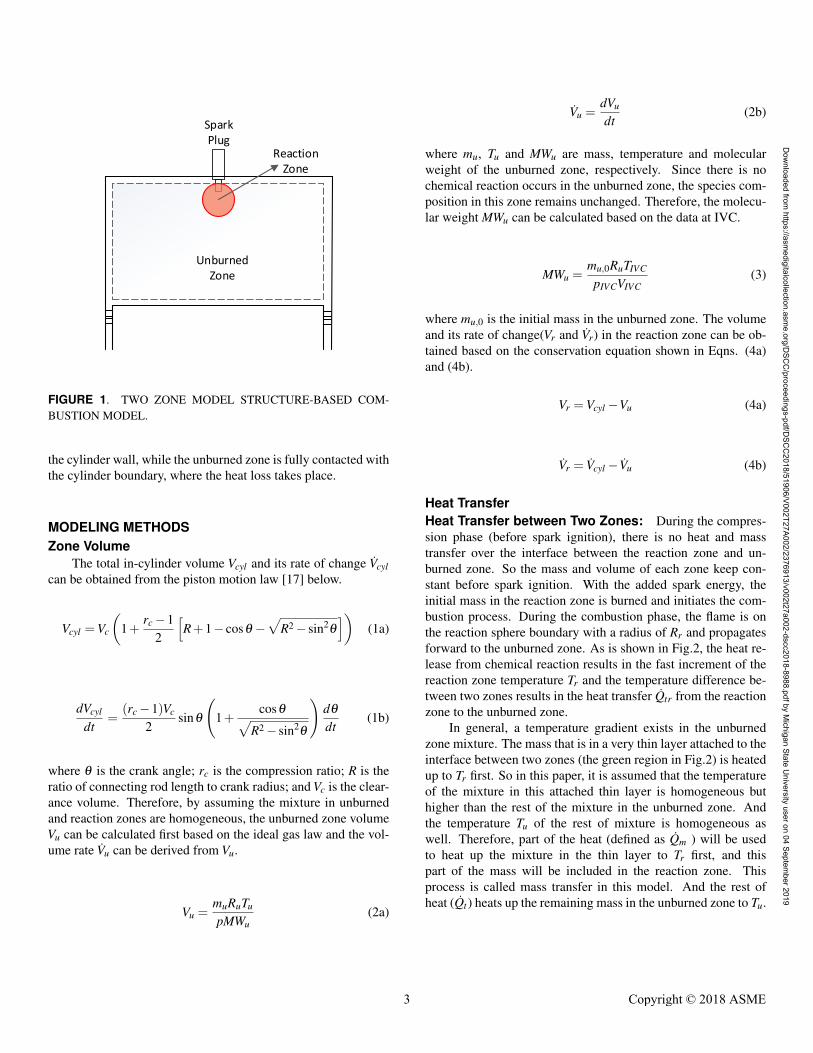
Heat TransferHeat Transfer between Two Zones: During the compres-sion phase (before spark ignition), there is no heat and masstransfer over the interface between the reaction zone and un-burned zone. So the mass and volume of each zone keep con-stant before spark ignition. With the added spark energy, theinitial mass in the reaction zone is burned and initiates the com-bustion process. During the combustion phase, the flame is onthe reaction sphere boundary with a radius of Rr and propagatesforward to the unburned zone. As is shown in Fig.2, the heat re-lease from chemical reaction results in the fast increment of thereaction zone temperature Tr and the temperature difference be-tween two zones results in the heat transfer Qtr from the reactionzone to the unburned zone.
In general, a temperature gradient exists in the unburnedzone mixture. The mass that is in a very thin layer attached to theinterface between two zones (the green region in Fig.2) is heatedup to Tr first. So in this paper, it is assumed that the temperatureof the mixture in this attached thin layer is homogeneous buthigher than the rest of the mixture in the unburned zone. Andthe temperature Tu of the rest of mixture is homogeneous aswell. Therefore, part of the heat (defined as Qm ) will be usedto heat up the mixture in the thin layer to Tr first, and thispart of the mass will be included in the reaction zone. Thisprocess is called mass transfer in this model. And the rest ofheat (Qt ) heats up the remaining mass in the unburned zone to Tu.
3 Copyright © 2018 ASME
Dow
nloaded from https://asm
edigitalcollection.asme.org/D
SCC
/proceedings-pdf/DSC
C2018/51906/V002T27A002/2376913/v002t27a002-dscc2018-8988.pdf by M
ichigan State University user on 04 Septem
ber 2019

FIGURE 2. INTERACTION BETWEEN TWO ZONES
The total heat transfer from the reaction zone to unburnedzone Qtr can be calculated based on 5.
Qtr = kcAtrTr−Tu
Rr(5)
where kc is the heat coefficient that needs to be calibrated; andAtr is the effective contact area between two zones. Since thereaction zone is supposed to be a sphere, Atr can be calculatedusing (6). Rr is the radius of the reaction zone, and is used as thedistance of the temperature gradient.
Atr = 4πRr2 (6)
The calculation of heat transfer Qm, used to define the mass trans-fer from the unburned zone to the reaction zone, is very impor-tant. For this model, it is assumed that there is no mass transferbetween the two zones until combustion starts. And most of themass in the unburned zone should be transferred to the reactionzone by the end of combustion. Then the following heat transferequation for Qm is proposed.
Qm =mu
mu +mrQtr (7)
The remaining heat transfer Qt used to increase the unburnedzone temperature can be obtained by
Qt = Qtr− Qm =mr
mu +mrQtr (8)
Heat Loss: It is assumed that the heat loss Qw only occursbetween the unburned zone and the cylinder boundary in thismodel; see Fig. 2. Heat loss affects the thermal stratifica-tion inside the cylinder and the combustion behavior [18]. TheWoschni’s formula [19] is used in this model to calculate the heatloss from the unburned zone to the cylinder boundary.
Qw = hcAw(Tu−Tw) (9)
where Aw is the heat transfer surface area between the unburnedzone and the cylinder boundary; hc is the heat transfer coeffi-cient; and Tw is the boundary temperature (assumed to be con-stant). The heat transfer surface Aw is given by
Aw =Ach +Ap
+πBL
2
[R+1− cosθ −
√R2− sin2
θ
] (10)
where Ach is the cylinder head surface area; Ap is the pistoncrown surface area; B is the cylinder bore; and L is the pistonstroke. The heat transfer coefficient hc is given by
hc = αB−0.2 p0.8T−0.55u (2.28Sp)
0.8 (11)
where α is a constant to be calibrated using experimental data;and Sp is the piston speed.
Mass and Mass Transfer
Mass Transfer between Two Zones: As mentioned in thelast section, the heat transfer Qm transfers the mass at the inter-face between two zones during the combustion phase. If massflow rate mtr were too high, the combustion would become irreg-ular; and if it were too slow, there will be not enough unburnedmixture to be burned to keep combustion going. Therefore, themass transfer between two zones is very important in this modeland it should be controlled appropriately. The following equationis used to calculate transfer rate.
mtr =kmQm
cp,u∆T0(12)
where km is mass coefficient; and ∆T0 (K) is a constant tempera-ture increment. These two parameters need to be calibrated.
4 Copyright © 2018 ASME
Dow
nloaded from https://asm
edigitalcollection.asme.org/D
SCC
/proceedings-pdf/DSC
C2018/51906/V002T27A002/2376913/v002t27a002-dscc2018-8988.pdf by M
ichigan State University user on 04 Septem
ber 2019

Zone Mass: The initial mass of the reaction zone and un-burned zone are about 1.5% and 98.5% of total mass, respec-tively. Total mass in the cylinder consists of fuel, fresh air andresidual burned gas (RBG) from the last cycle. In this paper, itis assumed that the mass of RBG is 7% of pre-mixed fuel andair mass at IVC. After combustion is initiated, the masses in twozones are obtained based on the mass transfer rate.
mu =∫ EVO
IVC−mtrdt , mu,0 = 98.5%mtot (13)
mr = mtot −mu (14)
Combustion ModelMolar Concentration and Concentration Rate: The mo-lar concentration and concentration rate of each species are thefoundation for further study of chemical reactions and thermo-dynamic properties of the mixture. The molar concentration isdefined as follows.
[Xi] =Ni
V(15)
where [Xi] (mol/m3) is the molar concentration of species i andNi is the molar number. Therefore, the molar concentration ratecan be derived as
[Xi] =1
V MWi
dmi
dt− Ni
V 2dVdt
(16)
where the first term on the right side of (16) accounts for theeffect of the mass change on molar concentration, while the sec-ond term is for the effective volume change. The mass changein a zone is due to mass flow in/out and the chemical reaction.Therefore, the mass change in the unburned zone is only dueto the mass flow, while the mass change in the reaction zone iscaused by chemical reactions and mass flow.
Chemical Reaction Rate: In order to model the chemicalreaction mechanism in the combustion process, a two-step reac-tion model shown in (M1) and (M2) is used in this paper. It isassumed that the fuel and oxygen are burned in the first step withthe productions of CO and H2O generated, and then the CO isburned in the second step to produce CO2 (a two-way reactionprocess).
C8H18 +172
O2k1−−→ 8CO+9H2O (M1)
CO+12
O2k2−−⇀↽−−k3
CO2 (M2)
The reaction rates of each step are represented by ωM1 andωM2, respectively, and are defined by
ωM1 = k1(T )[C8H18]n1 [O2]
n2 (17a)
ωM2 = k2(T )[CO]n3 [O2]n4 − k3(T )[CO2]
n5 (17b)
where ni (i = 1 ∼ 5) is the reaction order and is determined byexperimental data. [C8H18], [O2] et al. stand for the molar con-centration of each species. ki is the specific reaction rate con-stant, which is a function of temperature and can be given basedon the Arrhenius function [15], see below.
ki(T ) = Aie−Ea,i/RuT (18)
where Ea,i is the activation energy of the reaction with the unitof (J/mole) and Ai is the pre-exponential factor. Both of them areconstant and need to be calibrated based on experimental data.
Therefore, based on the discussion in this section, thespecies in the reaction zone are C8H18, O2, N2, CO2, H2O, CO,while in the unburned zone, without chemical reaction, there areonly five species, C8H18, O2, N2, CO2, H2O. Especially, differ-ent from the mixture in the reaction zone, both CO2 and H2O inthe unburned zone are from the trapped RBG with a very smallamount.
Zone Temperature: With the molar concentration and con-centration rate, the thermodynamic characteristic of each speciesin each zone can be obtained. Then, combining with the massand heat transfer, the second-law of thermodynamics can be usedto derive the zone temperature given below.
Tr =
Qign−QtVr
+RuTrΣ[Xi]−Σ[Xi]hi− VrVr
Σ[Xi]hi +Σ(Nihi)
Vr
Σ[Xi] (cp,i(T )−Ru)(19a)
5 Copyright © 2018 ASME
Dow
nloaded from https://asm
edigitalcollection.asme.org/D
SCC
/proceedings-pdf/DSC
C2018/51906/V002T27A002/2376913/v002t27a002-dscc2018-8988.pdf by M
ichigan State University user on 04 Septem
ber 2019

Tu =
Qt−QwVu
+RuTuΣ[Xi]−Σ[Xi]hi− VuVu
Σ[Xi]hi +Σ(Nihi)
Vu
Σ[Xi](cp,i(T )−Ru)(19b)
where the Qign in (19a) is the spark ignition energy; hi and cp,iare the molar enthalpy and specific heat of species i, respectively.both of them are temperature based.
Therefore, the averaged temperature in the cylinder is givenby
Tavg =mrTr +muTu
mtot(20)
In-Cylinder Pressure: With the temperature, mass and vol-ume of each zone calculated, the in-cylinder pressure can be ob-tained by the ideal gas law below.
p =mtotRuTavg
VcylMWmix(21)
where MWmix is the molecular weight of the cylinder mixture atIVC.
SIMULATION RESULTSThe proposed model is calibrated based on the experimen-
tal data from a 4-cylinder, four-stroke SI engine and the enginespecifications are given in Table 1. The calibrated parameters arelisted in Table 2.
TABLE 1. ENGINE SPECIFICATIONS.
Parameters Value Unit
Bore 86 mm
Stroke 86 mm
Rod 143.6 mm
Compression ratio 11:1 -
Displacement 499.56 cm3
Intake valve closing(IVC) 190◦ BTDC
Exhaust valve opening(EVO) 156◦ ATDC
Intake/exhaust valve lifts 5 mm
TABLE 2. CALIBRATION PARAMETERS.
Parameters Equations
kc (5)
α (11)
km,∆T0 (12)
Ai, Ea,i (18)
-150 -100 -50 0 50 100 1500
500
1000
1500
2000
2500
3000
Unburn Zone temperature
Reaction Zone temperature
FIGURE 3. PREDICTED TWO ZONE TEMPERATURES
The proposed two-zone reaction-based model was validatedfor the engine operation at 1500 and 2000 rpm under differentloads. The simulation results with IMEP = 6.83bar at the enginespeed of 2000 rpm are presented to show the model’s ability ofpredicting combustion process and thermodynamic states of themixture in the cylinder.
The modeled two zone temperatures are shown in Fig.3,which indicates that the two zone temperatures are the same be-fore spark ignition and then the reaction zone temperature jumpsup after the start of combustion (SOC) while the unburned zonetemperature does not increase at the same time. The reason isthat the heat released by the chemical reaction in the reactionzone is very high, compared with the heat transfer between twozones. However, due to the heat transfer from the reaction zone,the unburned zone temperature increases quickly at the end-stageof combustion. The temperature of the reaction zone increasesquickly at 15 degree before TDC because of the instant burn ofthe initial mass in the reason zone as well as the small volume(1-2% of total volume) of the reaction zone at the start of com-bustion.
6 Copyright © 2018 ASME
Dow
nloaded from https://asm
edigitalcollection.asme.org/D
SCC
/proceedings-pdf/DSC
C2018/51906/V002T27A002/2376913/v002t27a002-dscc2018-8988.pdf by M
ichigan State University user on 04 Septem
ber 2019

-20 -10 0 10 20 30 40 50
0
0.1
0.2
0.3
0.4
0.5
0.6
0.7
0.8
0.9
MFB
FIGURE 4. PREDICTED MASS BURNED RATE
-150 -100 -50 0 50 100 1500
0.5
1
1.5
2
2.5
3
106
Calculated
Experimental
-150 -100 -50 0 50 100 150-10
0
10
error
FIGURE 5. PREDICTED IN-CYLINDER PRESSURE AGAINSTEXPERIMENTAL DATA
The predicted MFB is shown in Fig.4. The slope of thiscurve shows that the burn rate is very fast from SOC to around20 CAD ATDC, where 50% of total fuel is burned. After that,the burn rate slows down until the end of combustion.
The simulated in-cylinder pressure is compared with exper-imental data, which is shown in Fig. 5. The simulation rela-tive error from SOC to EVO shown in this figure is within 5.3%which indicates that the proposed model is able to predict thein-cylinder pressure accurately. The oscillation at the early stageof compression, around 50 CAD BTDC after IVC, is from thesensor noise.
Since this model is able to calculate the molar concentra-tion of each species, it is able to predict the auto-ignition of endgas(engine knock). In summary, the simulation results shown inthis section demonstrate the capability of this proposed model topredict the combustion process and thermodynamic states of themixture as well as engine knock.
CONCLUSIONSA control-oriented, reaction-based two-zone thermody-
namic model for compression, combustion and expansion phasesof spark-ignition (SI) engines has been analytically developed,implemented in Simulink, calibrated and validated against ex-perimental data in this paper. The proposed model will bemainly used for predicting thermodynamic characteristics of in-cylinder mixtures, combustion process, properties of each indi-vidual chemical species in both reaction and unburned zones.
The experimental validation shows that the proposed two-zone model structure is able to predict the in-cylinder SI com-bustion process accurately with a simple calibration. Especially,it is able to simulate the in-cylinder thermal stratification charac-teristics. This confirms that the proposed two-zone model struc-ture with a two-step chemical reaction mechanism can be usedfor model-based combustion control; and furthermore, the ap-plication of two-step chemical reaction mechanism to the pro-posed model makes it possible to trace individual species stateand to predict the mass-fraction-burned, heat release rate, andin-cylinder pressure in real-time. That is, the effect of SI enginecontrol inputs to in-cylinder combustion process can be predictedand can be used for model-based combustion control.
REFERENCES[1] Bissoli, M., Frassoldati, A., Cuoci, A., Ranzi, E., Mehl,
M., and Faravelli, T., 2016. “A new predictive multi-zonemodel for HCCI engine combustion”. Applied Energy, 178,pp. 826–843.
[2] Trindade, W., and Gonalves dos Santos, R., 2016. “Com-bustion modeling applied to engines using a 1d simulationcode”. SAE International, 11.
[3] Verhelst, S., and Sheppard, C. G., 2009. “Multi-zone ther-modynamic modelling of spark-ignition engine combustion- An overview”. Energy Conversion and Management,50(5), pp. 1326–1335.
[4] Li, R., Huang, Y., Li, G., Han, K., and Song, H., 2013.“Calibration and validation of a mean value model for tur-bocharged diesel engine”. Advances in Mechanical Engi-neering, 5.
[5] Hall, C. M., Shaver, G. M., Chauvin, J., Petit, N., andIeee, 2012. “Combustion Phasing Model for Controlof a Gasoline-Ethanol Fueled SI Engine with Variable
7 Copyright © 2018 ASME
Dow
nloaded from https://asm
edigitalcollection.asme.org/D
SCC
/proceedings-pdf/DSC
C2018/51906/V002T27A002/2376913/v002t27a002-dscc2018-8988.pdf by M
ichigan State University user on 04 Septem
ber 2019

Valve Timing”. 2012 American Control Conference (Acc),pp. 1271–1277.
[6] Rakopoulos, C., and Michos, C., 2008. “Availability anal-ysis of a syngas fueled spark ignition engine using a multi-zone combustion model”. Energy, 33(9), pp. 1378 – 1398.
[7] Rakopoulos, C., and Michos, C., 2008. “Development andvalidation of a multi-zone combustion model for perfor-mance and nitric oxide formation in syngas fueled sparkignition engine”. Energy Conversion and Management,49(10), pp. 2924 – 2938.
[8] Hvezda, J., 2012. “Multi-Zone Models of Combustion andHeat Transfer Processes in SI Engines”. Journal of MiddleEuropean Construction and Design of Cars, 10(2), pp. 14–22.
[9] Ibrahim, A., and Bari, S., 2009. “A comparison betweenEGR and lean-burn strategies employed in a natural gas SIengine using a two-zone combustion model”. Energy Con-version and Management(12), pp. 3129–3139.
[10] Rakopoulos, C. D., Rakopoulos, D. C., Giakoumis, E. G.,and Kyritsis, D. C., 2004. “Validation and sensitivity anal-ysis of a two zone Diesel engine model for combustion andemissions prediction”. Energy Conversion and Manage-ment, 45(9-10), pp. 1471–1495.
[11] Lounici, M. S., Loubar, K., Balistrou, M., and Tazerout, M.,2011. “Investigation on heat transfer evaluation for a moreefficient two-zone combustion model in the case of naturalgas SI engines”. Applied Thermal Engineering, 31(2-3),pp. 319–328.
[12] Jia, N., Wang, J., Nuttall, K., Wei, J., Xu, H., Wyszynski,M. L., Qiao, J., and Richardson, M. J., 2007. “HCCI En-gine Modeling for Real-Time Implementation and ControlDevelopment”. IEEE/ASME Transactions on Mechatron-ics.
[13] Men, Y., Haskara, I., Wang, Y. Y., Chang, C. F., and Zhu,G. G., 2017. “Model-based calibration of the reaction-based diesel combustion dynamics”. Proceedings of theAmerican Control Conference, pp. 4735–4740.
[14] Men, Y., Haskara, I., Wang, Y.-Y., Chang, C.-F., andZhu, G., 2017. “Model-based calibration of reaction-baseddiesel combustion dynamics”. Proceedings of the Institu-tion of Mechanical Engineers, Part D: Journal of Automo-bile Engineering, nov.
[15] Law, C. K., 2006. Combustion Physics. Cambridge Uni-versity Press, Princeton University.
[16] Turns, S. R., 2012. An Introduction to Combustion: Con-cepts and Applications. New York: McGraw-Hill.
[17] Heywood, J. B., 1988. Internal combustion engine funda-mentals. New York : McGraw-Hill.
[18] Guzzella, L., and Onder, C. H., 2010. Introduction to Mod-eling and Control of Internal Combustion Engine Systems,Vol. 53. Berlin: Springer.
[19] Woschni, G., 1967. “A Universally Applicable Equation for
the Instantaneous Heat Transfer Coefficient in the InternalCombustion Engine”. SAE Technical Paper.
8 Copyright © 2018 ASME
Dow
nloaded from https://asm
edigitalcollection.asme.org/D
SCC
/proceedings-pdf/DSC
C2018/51906/V002T27A002/2376913/v002t27a002-dscc2018-8988.pdf by M
ichigan State University user on 04 Septem
ber 2019