a fault tolerant noc architecture for reliability
TRANSCRIPT

A Fault Tolerant NoC Architecture for Reliability Improvement and Latency Reduction
A. Ehsani Zonouz, M. Seyrafi, A. Asad, M. Soryani, M. Fathy, R Berangi Department of Computer Engineering
Iran University of Science & Technology Tehran, Iran
{AE_ Zonouz, Mehseyrafi, Arghavan_Asad}@comp.iust.ac.ir, {Soryani, MahFathy, rberangi}@iust.ac.ir
Abstract—With reducing feature size of transistors and increasing number of cores on a single chip, fault tolerance and reliability have become two significant challenges for IC designers.
Since chip design is extremely cost-sensitive, the fault tolerance redundancy must be provided at a reasonable cost. In this paper, a fault tolerant NoC architecture with cores linked to two switches instead of one, is proposed. This architecture is able to save cores with a faulty switch.
Also, to be more efficient and to compensate this redundancy, a new routing algorithm is suggested that can be dynamically reconfigured to escape faulty switches. According to evaluation of the proposed architecture, latency and reliability are improved.
Keywords- Network on Chip; Fault Tolerance; Reliability; Perfomance Metric
1. INTRODUCTION According to reduction in feature size of semiconductor
technology and following Moore’s Law, the number of transistors increases enormously and enables us to integrate complicated System-on-Chip (SoC) designs. Because of communication challenges in SoC architectures, NoCs are becoming the main solution for more performance improvement than the traditional communication structures.
Interconnection scheme in NoC has been proposed as a unified solution for the design problems faced in advanced process technology [1], [2].
According to the prediction from an Intel commentator in [3]: “within a decade we will see 100 billion transistor chips. That is the good news. The bad news is that 20 billion of those transistors will fail in manufacture and a further 10 billion will fail in the first year of operation”.
So, a 20%-30% transistor failure rate means that the fault-tolerant approach must be considered in NoC design.
Physical faults are divided into two categories in VLSI chips: Transient and Permanent faults. A comprehensive solution to deal with both permanent and transient faults affecting the VLSI chips has been proposed in [4] in which retransmission mechanism routes packets on alternate paths when a communication link or a router suffers permanent failure.
There are two main ways in a comprehensive approach to
fault tolerant design: avoidance and detection-recovery. The avoidance method is based on using high-quality
components and advanced equipments for manufacturing. These measures can increase the cost of a system significantly. This approach is suitable for designing devices that are used in sensitive and critical conditions. Therefore, detection and recovery methods are considered for designing fault tolerant systems as a cost effective way.
In this manner, when encountering defects, they are detected by test mechanisms which are embedded on chip. Then, recovery methods are used to nullify the effects of malfunctions on the application that is running on the chip.
Majority of recent researches in fault tolerant NoCs have concentrated on routing algorithms that are able to escape faulty switches.
In [5], a router is proposed which works in two phases. In the first phase, after detecting a fault, the network is explored for existing paths between source-destination pairs. Existing paths are cached and used in the second phase during normal system operation.
In [6], [7] some routing algorithms have been proposed (e.g. probabilistic and directed flooding) which are susceptible to failures during an initial phase of transmission. In probabilistic flooding, packets are sent to all of neighbors with probability p and are dropped with probability 1-p. In this algorithm, number of packets is increased exponentially and degrades the performance metrics. For improving probabilistic flooding, packets are sent with different probabilities that are determined based on the destination of the packet.
In [17], [18] a fault tolerant mesh based NoC architecture has been proposed. This architecture can recover from single permanent switch failures by adding a redundant link between each processing element and one of its neighboring switches based on the application that has been mapped on the chip. In this method causes the router’s architecture should change according to the application type and therefore cause that layout of the chip (especially switches) not to have symmetric design. Consequently all the design attempts must be restarted for each new application.
The next important topic for consideration is the evaluation of NoC metrics. Two most important metrics that must be evaluated in Fault-tolerant architectures are reliability and availability. Reliability and availability can
2009 12th Euromicro Conference on Digital System Design / Architectures, Methods and Tools
978-0-7695-3782-5/09 $25.00 © 2009 IEEE
DOI 10.1109/DSD.2009.170
473
Authorized licensed use limited to: Iran Univ of Science and Tech. Downloaded on January 16, 2010 at 10:46 from IEEE Xplore. Restrictions apply.

be evaluated analytically or using simulation. Extensive researches have evaluated reliability of Networks on Chip in [8], [9], and [10].
In this paper, a fault tolerant architecture for NoC implementation, called Dual Connected mesh Structure (DCS) and routing algorithm, called αβ-XY to improve the performance parameters are proposed. Also a comparison between the two most important NoC factors, latency and reliability, for the same sized mesh and DCS are done.
The rest of this paper is organized as follows. In section 2, a basic knowledge of NoC is presented. In section 3, the proposed fault tolerant architecture and also the new routing algorithm are described. In section 4, the reliability properties for both the proposed architecture and the routing algorithm are analyzed separately in two subsections. Performance and Cost metrics are presented in sections 5 and 6 respectively. Experimental results are presented in section 7. And conclusions are finally made in section 8.
2. PRELIMINARIES In this section, features and characteristics of the NoC
architecture and the application that is used in this paper are described.
2.1 NoC Architecture Fig. 1 shows a sample NoC structured as a 3×3 Mesh-
based network. The main components of a common NoC architecture are
described as below: • Network Interface (NI): Communication between a core
and its switch is done through this component. Its other important functions are capsulation and decapsulation of messages.
• Switch/Router: Receiving, routing and transmitting packets according to routing algorithm are three functions of the switch (router).
• Link: Interconnection between switches.
Figure 1. A common Mesh-based NoC
• Core: Different parts of the running application are mapped onto cores on chip.
The basic features of the NoC model used in this paper include: Wormhole switching, arbitration based on round-robin and buffers with FIFO strategy. The proposed routing algorithm is based on XY which is deadlock-free, but provides no adaptiveness. In which, first, a packet traverses along the X-dimension and then along the Y-dimension.
2.2 The Used Application The Multi-Window Displayer (MWD) application [11],
[12], is used for mapping onto cores. The communication task graph (CTG) of this application is shown in Fig. 2. The numbers on each edge are the amount of data transferred between two cores, in MB/s.
3. THE PROPOSED ARCHITECTURE In common NoC architectures, when a fault occurs on
one of the switches, its core loses communication with other cores and the running application on the chip will fail.
So, there is a dire need to have a fault tolerant architecture for saving cores with faulty switches. In the proposed architecture every core is connected to a master switch and a slave switch. The master switch of each core is the original switch in a common Mesh, depicted in Fig. 1.
The slave switch will be one of the neighbors of the master switch. For this purpose, the left switch is selected as the slave. The name DCS (Dual Connected mesh Structure) comes from this fact that each core is connected to two switches. Fig. 3 shows the proposed configuration.
Note that in Fig. 3 east border switches are connected to west border IP cores (Blue arrows mention it as an example).
3.1 Fault Tolerant Architecture If a master switch is failed, all of the communication
operations of its core will be done by the slave switch. Therefore a 6-port switch is needed for implementing this structure. Fault detection in each switch is done
Figure 2. CTG of Multi-Window Displayer (MWD)
474
Authorized licensed use limited to: Iran Univ of Science and Tech. Downloaded on January 16, 2010 at 10:46 from IEEE Xplore. Restrictions apply.
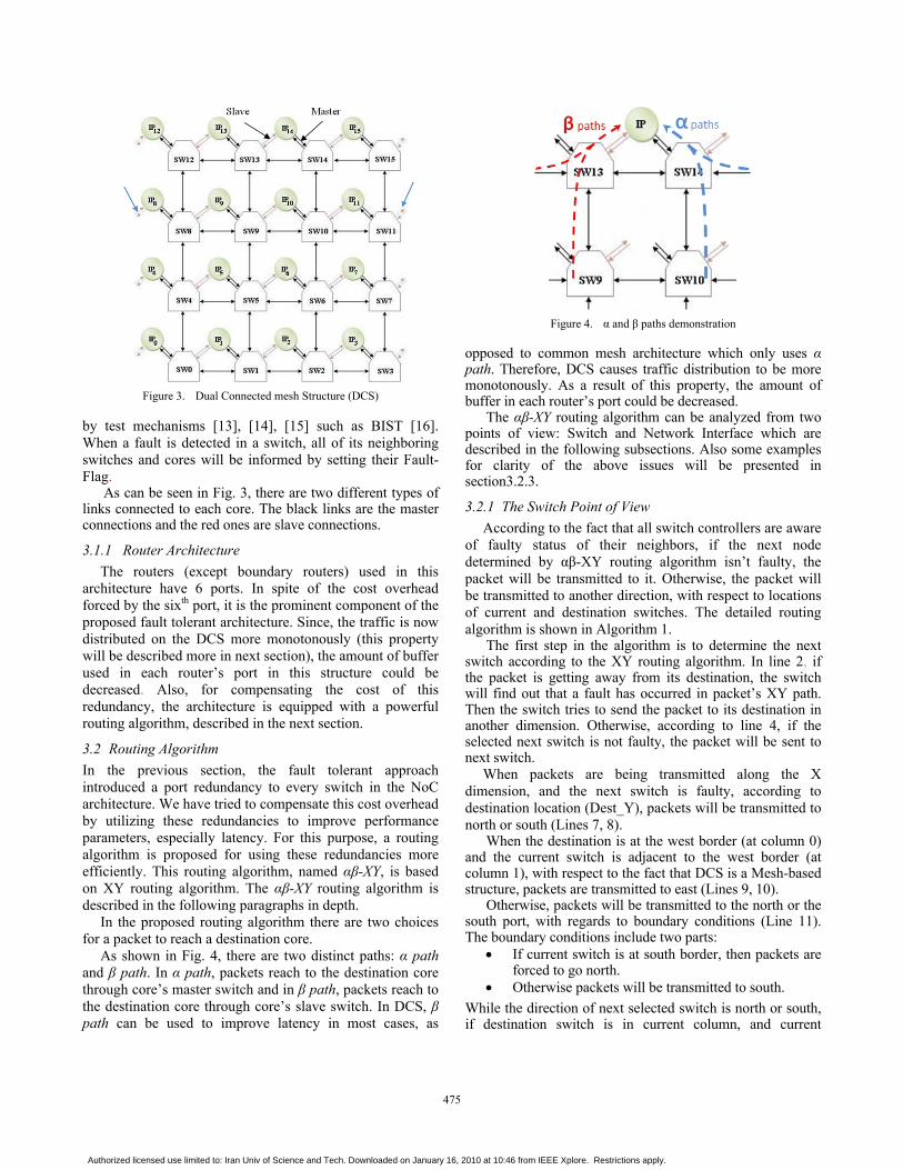
Figure 3. Dual Connected mesh Structure (DCS)
by test mechanisms [13], [14], [15] such as BIST [16]. When a fault is detected in a switch, all of its neighboring switches and cores will be informed by setting their Fault-Flag.
As can be seen in Fig. 3, there are two different types of links connected to each core. The black links are the master connections and the red ones are slave connections.
3.1.1 Router Architecture The routers (except boundary routers) used in this
architecture have 6 ports. In spite of the cost overhead forced by the sixth port, it is the prominent component of the proposed fault tolerant architecture. Since, the traffic is now distributed on the DCS more monotonously (this property will be described more in next section), the amount of buffer used in each router’s port in this structure could be decreased. Also, for compensating the cost of this redundancy, the architecture is equipped with a powerful routing algorithm, described in the next section.
3.2 Routing Algorithm In the previous section, the fault tolerant approach introduced a port redundancy to every switch in the NoC architecture. We have tried to compensate this cost overhead by utilizing these redundancies to improve performance parameters, especially latency. For this purpose, a routing algorithm is proposed for using these redundancies more efficiently. This routing algorithm, named αβ-XY, is based on XY routing algorithm. The αβ-XY routing algorithm is described in the following paragraphs in depth.
In the proposed routing algorithm there are two choices for a packet to reach a destination core.
As shown in Fig. 4, there are two distinct paths: α path and β path. In α path, packets reach to the destination core through core’s master switch and in β path, packets reach to the destination core through core’s slave switch. In DCS, β path can be used to improve latency in most cases, as
Figure 4. α and β paths demonstration
opposed to common mesh architecture which only uses α path. Therefore, DCS causes traffic distribution to be more monotonously. As a result of this property, the amount of buffer in each router’s port could be decreased.
The αβ-XY routing algorithm can be analyzed from two points of view: Switch and Network Interface which are described in the following subsections. Also some examples for clarity of the above issues will be presented in section3.2.3.
3.2.1 The Switch Point of View According to the fact that all switch controllers are aware
of faulty status of their neighbors, if the next node determined by αβ-XY routing algorithm isn’t faulty, the packet will be transmitted to it. Otherwise, the packet will be transmitted to another direction, with respect to locations of current and destination switches. The detailed routing algorithm is shown in Algorithm 1.
The first step in the algorithm is to determine the next switch according to the XY routing algorithm. In line 2, if the packet is getting away from its destination, the switch will find out that a fault has occurred in packet’s XY path. Then the switch tries to send the packet to its destination in another dimension. Otherwise, according to line 4, if the selected next switch is not faulty, the packet will be sent to next switch.
When packets are being transmitted along the X dimension, and the next switch is faulty, according to destination location (Dest_Y), packets will be transmitted to north or south (Lines 7, 8).
When the destination is at the west border (at column 0) and the current switch is adjacent to the west border (at column 1), with respect to the fact that DCS is a Mesh-based structure, packets are transmitted to east (Lines 9, 10).
Otherwise, packets will be transmitted to the north or the south port, with regards to boundary conditions (Line 11). The boundary conditions include two parts:
• If current switch is at south border, then packets are forced to go north.
• Otherwise packets will be transmitted to south.
While the direction of next selected switch is north or south, if destination switch is in current column, and current
475
Authorized licensed use limited to: Iran Univ of Science and Tech. Downloaded on January 16, 2010 at 10:46 from IEEE Xplore. Restrictions apply.

Algorithm 1 AlphaBeta_XY_Router ( Current, Dest ) 1: Next_Switch <- calculate next switch according to XY Algorithm 2: if Next_Switch retrace to the input dir3: then try to approach to dest in another dimension. 4: else if Next_Switch is not faulty 5: then transmit packet to Next_Switch else 6: if Next_Switch direction is East or West then 7: if Dest_Y is not equal to Current_Y 8: then Transmit packet to North or South, which is better according to Y offset else 9: if dest is on West Border and Current is adjacent to West border 10: then Transmit packet to East (to opposite dir) 11: else Transmit packet to North or South with regards to boundary conditions else 12: if Dest is not in current column and Current is in West border 13: then Transmit packet to East 14: else Transmit packet to West
Algorithm 2 AlphaBeta_XY_Core ( Core, Dest ) 1 : if both switches are working properly 2: Then Transmit to Master or Slave switch with regards to horizontal offset else 3: if one of switches (Master or Slave) is faulty 4: then Transmit to another switch (Slave or Master)
switch is in west border, packets are transmitted to east. Otherwise, packets are transmitted to west ( Lines 12, 13 and 14).
3.2.2 The Network Interface Point of View According to the fact that Network Interface has an
effective role in the routing algorithm on DCS architecture, its task in the routing algorithm is divided into two parts with respect to faulty status of connected switches to each core:
• Both Master and Slave are working properly: In this case, according to minimum horizontal distance
between source and destination switches, it will be decided which switch (master or slave) is better to transmit the packets.
• One of switches is faulty: The packets are forced to be transmitted to the working
switch. The routing algorithm from Network Interface point of
view is shown in Algorithm 2. In this algorithm, when both switches of core (master and slave) are working properly (line 1), packets are transmitted to the switch which has minimum horizontal distance to destination switch (line 2) and causes a reduction in hop count. Otherwise (when one of them is faulty), packets are transmitted to another switch compulsorily (line 3, 4).
Figure 5. Some example paths in DCS
3.2.3 Some Routing Algorithm Examples In this part, some examples are proposed to show the
difference between α path and β path and to explain the features of the routing algorithm.
As shown in Fig. 5, to send a packet from core 1 to core 11 using α path (A), hop count is 5 switches, but using β path (B), it will be improved and hop count will be 4 switches. Moreover this decreasing in hop count leads to reduced total buffering time, and consequently total latency. Now consider the case where in the common mesh based topology, core 3 is sending packets to core 11 (path C) and at the same time core 1 is sending packets to core 11 (A); This situation could cause traffic congestion but in DCS, path C along with path B distributes traffic into two paths. Therefore, using DCS makes traffic distribution more monotonously.
Another example in Fig. 5 is when switch 8 is faulty and all of its neighbors (switches 12, 9, and 4) are aware of its faulty status by an embedded on chip test strategy. For setting communication between core 12 and core 0, core 12 sends packets to switch 12. Then packets will be transmitted to switches 13, 9, 5, 4 and 0 respectively, based on αβ-XY routing algorithm.
As another example, to establish connection between core 9 and core 8, in normal condition (without any faults on the path), packets are transmitted to switch 8 and then to core 8, based on αβ-XY routing algorithm. But, when there is a fault on switch 8, packets are transmitted to switches 9, 10, 11 and core 8, respectively.
4. EVALUATION OF RELIABILITY In this section, we demonstrate reliability considerations
of the proposed architecture and routing algorithm and their evaluation. Moreover a reliability model will be presented in depth.
476
Authorized licensed use limited to: Iran Univ of Science and Tech. Downloaded on January 16, 2010 at 10:46 from IEEE Xplore. Restrictions apply.

Consider a functional module that is operational at time t=0 and remains operational until a failure occurs.
The reliability of a functional module is the probability function R(t), t≥0, that the system will operate properly with no repair until time t. Another measure used to describe the system reliability characteristics is Mean Time To Failure (MTTF) as shown in Equation 1 [10].
0 ( )MTTF R t dt∞= ∫ (1)
With constant failure-rate (λ) [10]: 1MTTFλ
= (2)
And ( ) tR t e λ−= (3)
A system can contain series and/or parallel modules. The reliability of a series system is the multiplication of all modules reliabilities:
_0
( ) ( )n
S e r i e s S y s t e m ii
R t R t=
= ∏
(4)
Where Ri is reliability of a single module. And reliability of a parallel system is:
_0
( ) 1 (1 ( ))n
Parallel System ii
R t R t=
= − −∏ (5)
Another measure which is more important than reliability is availability. That is the probability function A(t), t≥0, that the system will operate properly. Reliability R(t) and availability A(t) is the same for non-repaired systems.
4.1 Reliability Evaluation Based on Routing Algorithm In a common mesh, based on XY routing algorithm, in
case of a fault in a path between each pair of source and destination, in addition to loosing the mentioned core, the transmitted packets will never be received. The reason is that no fault tolerant solution has been planned in common mesh. Therefore, it treats as a series system. As an example in Fig. 5, for communicating between core 1 and core 15, reliability is equal to equation 6:
R Path 1 to 15 = R1× Rsw2× Rsw3× Rsw7× Rsw11× Rsw15 (6)
Whenever one of the switches on the path gets faulty, the connection between source and destination will fail, and according to XY routing algorithm there will not be any alternative path between them.
According to the fault tolerant αβ-XY routing algorithm, if one of the switches in the path gets faulty, there will be alternative paths undoubtedly and in case of a couple of faulty switches in the path, there will be alternative paths with a high probability.
Figure 6. MWD mapped on DCS
For the previous example, while there is a defect on switch 2, packets will be routed from a bypass path (from β path) through switches 1, 5, 6, 10 and 14, to escape switch 2. Note that in the normal conditions (no fault in the path), packets are routed from β path through 1, 2, 6, 10 and 14 respectively. Reliability of the path between core 1 and core 15, with respect to different faults on the path, is derived from equation 7:
R Path 1 to 15 = Rsw1× (Rsw2×( Rsw6×( Rsw10×( Rsw14+ sw14 ×Rsw11 ×Rsw15 ) + sw10 × Rsw7 × Rsw11 × Rsw15 ) + sw6 × Rsw3 × Rsw7 × Rsw11 × Rsw15 ) + sw2 × Rsw5 × Rsw6 × Rsw10 × Rsw14 ) + sw1 × Rsw0 × Rsw4 × Rsw5 × Rsw6 × Rsw10 ×Rsw14 ) (7)
Where i is unreliability of a single module and is equal to 1 - Ri.
With respect to Fig. 6, in which MWD application has been mapped on a 4×4 DCS, the reliability of total communication path between each pair of cores in the demonstrated CTG (Fig. 2), can be calculated. For instance, the reliability of two paths (core 13 (in) to core 14 (nr) and core 13 (in) to core 9 (hs)) in the common mesh and DCS has been calculated and shown in Table I.
After computing reliability of some paths in CTG (Fig.2) and analyzing them, total reliability of DCS can be formulated as:
TABLE I. RELIABILITY OF SOME EXAMPLE PATHS IN DCS
Path Mesh DCS in → nr Rsw13 × Rsw14 Rsw13 + sw13 × Rsw12 × Rsw8 × Rsw9
× Rsw10 × Rsw14 in → hs Rsw13 × Rsw9 Rsw13 × Rsw9 + sw13 × Rsw12 × Rsw8
+ sw9 × Rsw13 × Rsw12 × Rsw8
477
Authorized licensed use limited to: Iran Univ of Science and Tech. Downloaded on January 16, 2010 at 10:46 from IEEE Xplore. Restrictions apply.

(8)
Which: nPath: Number of edges in CTG MainPathLeni: Length of ith edge
AltPathLeni,k: Alternative path for ith edge when kth switch is faulty
RPi,j : Reliability of jth switch on ith Path : Reliability of Lth switch on ith Path when kth switch
on ith path is faulty For equal switch reliabilities, the above formula is
simplified to:
(9)
4.2 Availability evaluation of each core based on DCS A powerful model for deriving the availability
expressions of complex systems is Markov Model [10]. The Markov model for each core in DCS is shown in Fig. 7 on the assumption that the core (IP) is perfect and its reliability is equal to one.
The differential equations for describing the Markov model of each core in DCS are:
(10)
(11)
(12)
Where Pi(t) is the time dependent probability of a core being in state i and i shows the number of working switches. Solving the above equations with initial condition P2(0)=1, P1(0)=P0(0)=0 yields:
(13)
Figure 7. Markov model of each core in DCS
Availability of each core in DCS is when the core is in state 1 or state 2 and at least one of the switches is working. Then it equals to:
A(t) = P1(t) + P2(t) (14)
The availability of cores in DCS and common Mesh are shown in Fig. 8 according to equations 3 and 14 respectively.
Fig. 8(a) shows the availability of cores with λ=0.05 (Rswi (1 year)= 0.95) [10]. As it can be seen in the figure, there is a significant increase in availability of the DCS as compared with common Mesh architecture. This improvement which is 18% in average and 25% in the best case, comes from the dual nature of DCS. The improvement depicted in Fig. 8 represents the architectural improvements solely. And it does not include improvements gained by the αβ-XY routing algorithm which was formulated in equation 8.
Figures 8(b) and 8(c) show the results for λ = 0.12 (Rswi (1year) = 0.88) and 0.25 (Rswi (1 year) = 0.78), respectively [3].
5. PERFORMANCE METRICS A packet is divided into fixed length flits. The header flit
holds the routing information such as packet ID, flit ID, source and destination. It establishes a path between source and destination. Subsequently, body flits follow that path and tail flit disconnects the path.
Most important metrics for comparing different NoC architectures are throughput, latency, energy and area overhead [19]. But this paper focuses on latency and hop count which have a major impact on throughput.
Throughput is a metric that quantifies the rate in which packet traffic can be sent across the network. It can be defined as the number of accepted flits per core per cycle.
Therefore it is closely related to the maximum amount of sustainable traffic in a specific network type.
Figure 8. Availability of cores in DCS and Common Mesh architectures
(a) λ = 0.05 (b) λ = 0.12 (c) λ = 0.25
478
Authorized licensed use limited to: Iran Univ of Science and Tech. Downloaded on January 16, 2010 at 10:46 from IEEE Xplore. Restrictions apply.

It can be improved by two factors: the number of physical links and the average number of hops. A network with greater number of links can tolerate a greater number of flits.
The number of links in a mesh-based NoC is given as follows:
Links = N1 × (N2 - 1) +N2 × (N1 - 1) + N1 × N2 (15)
Where, Ni represents the number of switches in the ith dimension. Note that the last part of Eq.15 (N1 × N2) is the number of links between cores and switches.
The number of links in the DCS NoC is given as:
Links = N1 × (N2 - 1) +N2 × (N1 - 1)+ 2 × N1 × N2 (16)
The difference between eq.15 and eq.16 comes from the slave links added to the mesh structure.
Despite of the trivial effect of slave links on the overall throughput in DCS, considering only the number of links will not characterize the throughput of the network. The average hop count also has a definitive effect on throughput as mentioned above.
6. COST METRICS NoC cost metrics is a multifaceted problem which can
include silicon area, power consumption, and bit-error rate due to cross-talk and external influences [21].
To compare the proposed DCS with the common Mesh, a simple cost model for the silicon area metric and another model for estimating number of flip-flop of router is used.
This model is proposed to derive the area of the router and NI as function of their parameters. For example consider the router area as function of its components. There are parts of the router whose area is linear in the component (e.g. the control and queuing) and parts that are quadratic in the component (e.g. the switch inside the router) [21].
By way of illustration, consider the router having 48 words input queue depth has been synthesized in a 0.13μm CMOS process for a clock frequency of 500 MHz and data path width of 32 bits (for each link/port). The resulting cost model given in terms of component α is [21]:
AR (α) = 0.808 × α2 + 23 × α (μm2) (17)
Similarly, the following area function is derived for NI:
ANI (p, c, q) = 19.6 × p × c + 0.72× p × c × q + 4.8 (μm2) (18)
Where p is the number of ports of the NI, c is the number of connections per port, and q is the depths of the queues in NI.
As another point of view, the number of flip-flop in router could be a significant parameter for the area cost of router. The number of flip-flops in router is given as [22]:
#FF≅ #Ports×[(FlitSize+2)×BufSize + log2 (BufSize × (#Port)2)] (19)
According to Eq.19, for equal condition, the number of flip-flop in DCS is greater than common Mesh. Nonetheless, the Buffer Size could be decreased, with respect to this fact that traffic in DCS is distributed monotonously.
7. EXPERIMENTAL RESULTS To compare the proposed αβ-XY routing algorithm with
the common XY algorithm, a simulator was developed in SystemC. Each input channel in routers has a buffer size of 8 flits and each flit has a size of 40 bits. The packet length is assumed to be 6 flits. Each simulation was run initially for 5,000 cycles, to allow network to become stable (Warm-up), and the results were gathered for a period of 40,000 cycles.
Two simulation profiles were performed. The first was based on transpose traffic. In this traffic, ith core sends packets only to (N - 1 - i)th core[20]. Bursty traffic pattern is used for injecting packets into the network. Simulation results were obtained for a 9×9 mesh and a 9×9 DCS. In Fig. 9, the average packet latency is plotted as a function of packet injection rate at each node for the mesh and DCS architectures using XY and αβ-XY routing algorithms.
Note that the network interface is equipped with an admission control mechanism by credit lines. So packet injection is controlled and therefore latency will be guaranteed for the admitted packets.
As can be seen in the figure, DCS has smaller average packet latency with respect to the equivalent mesh network. The reasons are that using α and β paths in DCS makes traffic distribution more monotonously and using master and slave links causes the reduction hop counts in most cases.
Figure 9. Packet latency in Mesh vs. DCS Figure 10. Hop count in Mesh vs. DCS
479
Authorized licensed use limited to: Iran Univ of Science and Tech. Downloaded on January 16, 2010 at 10:46 from IEEE Xplore. Restrictions apply.
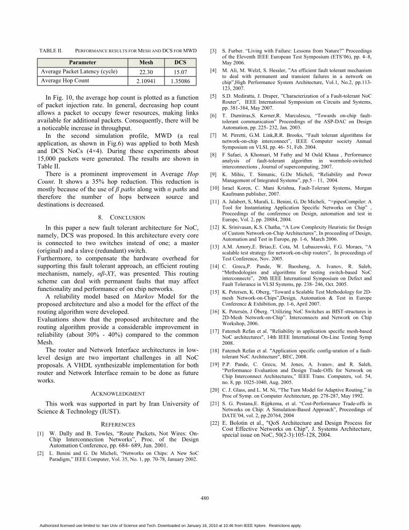
TABLE II. PERFORMANCE RESULTS FOR MESH AND DCS FOR MWD
Parameter Mesh DCS Average Packet Latency (cycle) 22.30 15.07 Average Hop Count 2.10941 1.35086
In Fig. 10, the average hop count is plotted as a function
of packet injection rate. In general, decreasing hop count allows a packet to occupy fewer resources, making links available for additional packets. Consequently, there will be a noticeable increase in throughput.
In the second simulation profile, MWD (a real application, as shown in Fig.6) was applied to both Mesh and DCS NoCs (4×4). During these experiments about 15,000 packets were generated. The results are shown in Table II.
There is a prominent improvement in Average Hop Count. It shows a 35% hop reduction. This reduction is mostly because of the use of β paths along with α paths and therefore the number of hops between source and destinations is decreased.
8. CONCLUSION In this paper a new fault tolerant architecture for NoC,
namely, DCS was proposed. In this architecture every core is connected to two switches instead of one; a master (original) and a slave (redundant) switch. Furthermore, to compensate the hardware overhead for supporting this fault tolerant approach, an efficient routing mechanism, namely, αβ-XY, was presented. This routing scheme can deal with permanent faults that may affect functionality and performance of on chip networks.
A reliability model based on Markov Model for the proposed architecture and also a model for the effect of the routing algorithm were developed. Evaluations show that the proposed architecture and the routing algorithm provide a considerable improvement in reliability (about 30% - 40%) compared to the common Mesh.
The router and Network Interface architectures in low-level design are two important challenges in all NoC proposals. A VHDL synthesizable implementation for both router and Network Interface remain to be done as future works.
ACKNOWLEDGMENT This work was supported in part by Iran University of
Science & Technology (IUST).
REFERENCES [1] W. Dally and B. Towles, “Route Packets, Not Wires: On-
Chip Interconnection Networks”, Proc. of the Design Automation Conference, pp. 684- 689, Jun. 2001.
[2] L. Benini and G. De Micheli, “Networks on Chips: A New SoC Paradigm,” IEEE Computer, Vol. 35, No. 1, pp. 70-78, January 2002.
[3] S. Furber. “Living with Failure: Lessons from Nature?” Proceedings of the Eleventh IEEE European Test Symposium (ETS’06), pp. 4–8, May 2006.
[4] M. Ali, M. Welzl, S. Hessler, ”An efficient fault tolerant mechanism to deal with permanent and transient failures in a network on chip”,High Performance System Architecture, Vol.1, No.2, pp.113-123, 2007.
[5] S.D. Mediratta, J. Draper, ”Characterization of a Fault-tolerant NoC Router”, IEEE International Symposium on Circuits and Systems, pp. 381-384, May 2007.
[6] T. Dumitras,S. Kerner,R. Marculescu, “Towards on-chip fault-tolerant communication” Proceedings of the ASP-DAC on Design Automation, pp. 225- 232, Jan. 2003.
[7] M. Pirretti, G.M. Link,R.R. Brooks, “Fault tolerant algorithms for network-on-chip interconnect”, IEEE Computer society Annual Symposium on VLSI, pp. 46- 51, Feb. 2004.
[8] F Safaei, A Khonsari, M Fathy and M Ould Khaua , Performance analysis of fault-tolerant algorithm in wormhole-switched interconnections , Journal of supercomputing, 2007.
[9] K. Mihic, T. Simunic, G.De Micheli, “Reliability and Power Management of Integrated Systems”, pp.5 – 11, 2004.
[10] Israel Koren, C. Mani Krishna, Fault-Tolerant Systems, Morgan Kaufmann publisher, 2007.
[11] A. Jalabert, S, Murali, L. Benini, G, De Micheli, “×pipesCompiler: A Tool for Instantiating Application Specific Networks on Chip” , Proceedings of the conference on Design, automation and test in Europe, Vol. 2, pp. 20884, 2004.
[12] K. Srinivasan, K.S. Chatha, “A Low Complexity Heuristic for Design of Custom Network-on-Chip Architectures”, In proceeding of Design, Automation and Test in Europe, pp. 1-6, March 2006.
[13] A.M. Amory,E. Briao,E. Cota, M. Lubaszewski, F.G. Moraes, “A scalable test strategy for network-on-chip routers”, In proceedings of Test Conference, Nov. 2005.
[14] C. Grecu,P. Pande, W. Baosheng, A. Ivanov, R. Saleh, “Methodologies and algorithms for testing switch-based NoC interconnects”, 20th IEEE International Symposium on Defect and Fault Tolerance in VLSI Systems, pp. 238- 246, Oct. 2005.
[15] K. Petersen, K. Oberg, “Toward a Scalable Test Methodology for 2D-mesh Network-on-Chips”,Design, Automation & Test in Europe Conference & Exhibition, pp. 1-6, April 2007.
[16] K. Petersén, J Öberg. “Utilizing NoC Switches as BIST-structures in 2D-Mesh Network-on-Chip”. Interconnects and Network on Chip Workshop, 2006.
[17] Fatemeh Refan et al. "Reliability in application specific mesh-based NoC architectures", 14th IEEE International On-Line Testing Symp 2008.
[18] Fatemeh Refan et al. "Application specific config-uration of a fault-tolerant NoC Architecture", BEC, 2008.
[19] P.P. Pande, C. Grecu, M. Jones, A. Ivanov, and R. Saleh, “Performance Evaluation and Design Trade-Offs for Network on Chip Interconnect Architectures,” IEEE Trans. Computers, vol. 54, no. 8, pp. 1025-1040, Aug. 2005.
[20] C. J. Glass, and L. M. Ni, “The Turn Model for Adaptive Routing,” in Proc of Symp. on Computer Architecture, pp. 278-287, May 1992.
[21] S. G. Pestana,E. Rijpkema, et al. “Cost-Performance Trade-offs in Networks on Chip: A Simulation-Based Approach”, Proceedings of DATE’04, vol. 2, pp.20764, 2004
[22] E. Bolotin et al., "QoS Architecture and Design Process for Cost Effective Networks on Chip", J. Systems Architecture, special issue on NoC, 50(2-3):105-128, 2004.
480
Authorized licensed use limited to: Iran Univ of Science and Tech. Downloaded on January 16, 2010 at 10:46 from IEEE Xplore. Restrictions apply.