a formal approach to the definition and the design of
TRANSCRIPT

A Formal Approach to the Definition and the Design of Conceptual Schemata for Database Systems
CARLO ZANIOLO and MICHEL A. MELKANOFF
University of California at Los Angeles
A formal approach is proposed to the definition and the design of conceptual database diagrams to be used as conceptual schemata in a system featuring a multilevel schema architecture, and as an aid for the design of other forms of schemata. We consider E-R (entity-relationship) diagrams, and we introduce a new representation called CAZ-graphs. A rigorous connection is established between these diagrams and some formal constraints used to describe relationships in the framework of the relational data model. These include functional and multivalued dependencies of database relations. The basis for our schemata is a combined representation for two fundamental structures underlying every relation: the first defined by its minimal atomic decompositions, the second by its elementary functional dependencies.
The interaction between these two structures is explored, and we show that, jointly, they can represent a wide spectrum of database relationships, of which the well-known one-to-one, one-to- many, and many-to-many associations constitute only a small subset. It is suggested that a main objective in conceptual schema design is to ensure a complete representation of these two structures. A procedure is presented to design schemata which obtain this objective while eliminating redundancy. A simple correspondence between the topological properties of these schemata and the structure of multivalued dependencies of the original relation is established. Various applications are discussed and a number of illustrative examples are given.
Categories and Subject Descriptors: H.2.1 [Database Management]: Logical Design--data models; schema and subschema
General Terms: Design
1. INTRODUCTION
Conceptual schemata in database management systems (DBMSs) are expected to yield benefits in three domains:
(a) Data Independence. A three schema level architecture, such as the one proposed by the ANSI/X3/SPARC [31], provides a high degree of physical and logical data independence. In this architecture the conceptual schema occupies a central position between the multiple views seen by the users
Authors’ present addresses: C. Zaniolo, Bell Laboratories, Hohndel, NJ 07733; M. A. Melkanoff, Computer Science Department, University of California, Los Angeles, CA 90024. Permission to copy without fee all or part of this material is granted provided that the copies are not made or distributed for direct commercial advantage, the ACM copyright notice and the title of the publication and its date appear, and notice is given that copying is by permission of the Association for Computing Machinery. To copy otherwise, or to republish, requires a fee and/or specific permission. 0 1982 ACM 0362-5915/82/0300-024 $00.75
ACM Transactions on Database Systems, Vol. 7, No. 1, March 1982, Pages 024-059.

Conceptual Schemata for Database Systems * 25
(external schemata) and the internal schema which describes the physical organization of the database. The conceptual schema establishes the logical and functional connections between the internal and external levels.
(b) Design Aid. In a top-down methodology a conceptual schema supplies a logical representation from which a physical implementation is designed to maximize performance on typical queries and/or updates.
(c) Liaison to the Enterprise World. A conceptual model, also called an enter- prise schema, is often advocated as a means for successful communication between the data processing department and the rest of the enterprise.
In order to realize the benefits just considered, a conceptual schema must describe the intrinsic logical relationships among external data independent of the underlying implementation (by external data we denote information of interest to the enterprise as opposed to data introduced by the data processing department for the purpose of storing and processing this information). To obtain this objective, a conceptual schema must satisfy two requirements. The first is that the schema must be capable of characterizing completely and unambiguously the various relationships among external data; following GUIDE and SHARE [19], we refer to this as the complete relatability requirement. The second is that the schema must be expressive and concise.
The second requirement is most naturally met by using graphical representa- tions and diagrams. Early forms of graphical schemata such as hierarchies and networks are generally considered not suited for a conceptual representation since they combine information about logical structure of data with access path description, leaving some ambiguity as to the exact nature of the former. Thus new forms of graphical schemata have been proposed to express the logical structure of external data in an implementation-independent fashion. Among the many which were proposed are those presented in [9, 25, 271. Of these, we only discuss E-R (entity-relationship) diagrams [9], which have gained considerable acceptance in the field.
A common thrust of these works consists in analyzing and characterizing by means of examples the various relationships commonly encountered in a DBMS, and in proposing graphical representations for it. The designer who is cognizant of the semantics of his data is then expected to recognize similar relationships for the database at hand and produce a schema which reflects his understanding of the structure of his data. While these approaches have contributed to the understanding of data semantics, they have failed to achieve the degree of definiteness and mathematical rigor which by contrast is available in the frame- work of the relational approach to database systems. This paper presents a rigorous approach to the definition and the design of graphical schemata in the framework of the relational data model. This approach uses and applies various concepts and analytical tools which were presented in a companion paper [33].
2. BASIC CONCEPTS
We assume that the reader is familiar with the most common concepts pertaining to relational database theory, including the definition of relations, projections,
ACM ‘ikmsactions on Database Systems, Vol. 7, No. 1, March 1982.

26 9 C. Zaniolo and M. A. Mblkanoff
joins, functional dependencies, and multivalued dependencies. Date’s book [13] provides the reader with an introduction to these topics, whereas Beeri et al. [5] supply a sophisticate’s review and a list of more advanced readings. The notation and terminology used here is the same as that used in [33]. Thus, if R (iI) is a relation with attribute set a, and r and A are two subsets of a, we write F + A or I’ - A to denote, respectively, that A is functionally dependent (FD) on r or that A is multivalued dependent (MD) or I’. We may write r 4 A or r + A to denote that those dependencies do not hold. If the FD “f: I? + A” holds in R, then the MD ‘g : I? ++ A” also holds in R; g will be called the MD counterpart of fi The A-projection of R @)(A c a) will be denoted IIR (A). The natural join of relations R (9) and S(A) is denoted R(Q) *S(A). When s1 and A are disjoint (i.e., their intersection is empty) this natural join reduces to the Cartesian product R(Q) x S(A). Natural joins are commutative and associative. Thus we can refer to the natural join of a set of two or more relations without specifying the order in which this join is computed. By convention, R is the natural join of the singleton set {R} .
2.1 The Decomposition Approach
We follow the decomposition approach to relational schema design [ll, 15, 331. In this approach, the design is developed through a sequence of successive refinement steps as follows:
(i) Generate a first gross description of the database as a set of relations. (ii) Derive the’ set of functional and multivalued dependencies which hold for
these relations at every instant in time. (iii) Use these dependencies to recast the initial set of relations into the desired
schema.
This design discipline is certainly laborious, but it deserves our attention because it is rigorous and it improves our understanding of the structure of conceptual schemata.
For concreteness, let us consider an example. Assume that we need some information regarding departments of a given organization. More precisely, we are interested in the following relationships:
(1) the employees working in a department (an employee works in only one department);
(2) the salary of each employee (an employee only has one salary); (3) the name of the department manager (a department only has one manager); (4) the location of a department (we will assume that a department can only
have one location).
As the first step, we can represent this information in a single table, say DEPT, with the following attributes:
DN: unique names identifying department; SAL: annual salaries in dollars; E#: unique numbers identifying employees;
ACM Transactions on Database Systems, Vol. 7, No. 1, March 1982
Conceptual Schemata for Database Systems * 27
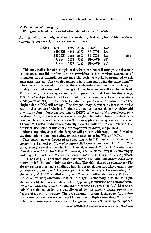
MGN: names of managers; LOC: geographical locations (at which departments are located).
At this point, the designer should consider typical samples of his database content. In our case, for instance, we could have
DEPT (DN, Ef, SAL, MGN, LOC) SHOES 4441 20K SMITH LA SHOES 3321 25K SMITH LA (2.1) TOYS 1121 30K BROWN SF TOYS 7321 10K BROWN SF
This materialization of a sample of database content will prompt the designer to recognize possible ambiguities or oversights in his previous statement of intension. In our example, for instance, the designer would be prompted to ask such questions as: “Can two departments have managers with the same name?” Thus he will be forced to resolve these ambiguities and perhaps to clarify or modify the initial statement of intension. Other basic issues will also be resolved. For instance, if the designer wants to represent two distinct locations, say, location of a department and location at which an employee lives, the obvious inadequacy of (2.1) to hold these two distinct pieces of information under the single column LOC will emerge. The designer may therefore be forced to revise his initial selection of relations. In the situation just discussed, he may either add one more column denoting locations to DEPT or he may add a completely new relation. Thus, this materialization ensures that the initial choice of relations is compatible with the stated intension. Thus an application of syntactically correct FD and MD rules produces semantically correct results within each relation. For a further discussion of this subtle but important problem, see [S, 15,331.
After completing step (i), the designer will proceed with step (ii) and formalize the time-independent constraints on these relations using FDs and MDs.
This operation was discussed at some length in [33], where the concepts of elementary FD and multiple elementary MD were introduced. An FD of R is called elementary if it has the form I’ + A, where A P I and R contains no I” + A where F’ c I’. An MD of R, P + A, is called elementary if A is nonempty and disjoint from I’ and R does not contain another MD, say, I” --H A’, where I” c I’ and A’ c A. Therefore, both elementary FDs and elementary MDs have minimum left side and minimum right side. The right side of an elementary FD always reduces to a single attribute, but that of an elementary MD contains one or more attributes. The MD counterpart of an elementary FD is elementary. An elementary MD of R is called multiple if R contains other elementary MDs with the same left side; otherwise, it is called single. Elementary FDs and multiple elementary MDs have a simple structure appealing to intuition and certain formal properties which may help the designer in carrying out step (ii) [33]. Moreover, only these dependencies are actually used by the schema design procedures discussed later in this paper. Thus, we assume that our designer performs step (ii) by simply listing the elementary FDs and the multiple elementary MDs which hold in a time-independent manner in the given relations. This discipline, applied
ACM Transactions on Database Systems. Vol. 7, No. 1, March 1982.

28 - C. Zaniolo and M. A. Melkanoff
to relation (2.1), yields the following list:
Dl: E# + SAL
D2: E# + DN
D3: E# + MGN
D4: E# + LOC
D5: DN + MGN
D6: DN + LOC
D7: DN - {E#, SAL)
(2.2)
The multiple elementary MDs for a relation are given as follows: in general, we list the elementary FDs and the multiple elementary MDs of a relation. For simplicity, however, we do not actually list the MD counterpart of an elementary FD. Thus, in (2.2), the MD counterpart of Dl is not explicitly given. However, since one knows that Dl is an elementary FD, he also knows that its MD counterpart “E# ++ SAL” is elementary. Some other elementary dependencies with left-hand side E# are also listed in (2.2); thus one knows that this elemen- tary MD is also multiple. Each FD (MD) of a relation-can be constructed from its elementary FDs (MDs) using the rules of reflexivity, additivity, and augmenta- tion [33].
At the end of step (ii), a set of relations is obtained, each defined by its attribute set and by its elementary FDs and multiple elementary MDs. Next, the designer will proceed with step (iii) as described in the following sections. We will always use the term “relation” in the sense of “description of a relation.” To refer to the extension of a relation, we use terms such as “content of a relation” or “instance of a relation.”
2.2 Schema Design
The approach to relational schema definition proposed by Codd is based on the concept of relational keys and normal forms [ll]. A key for a relation is an attribute combination which nonredundantly identifies each row of the relation (i.e., F is a key for R(a) iff I’ + Q and for each A c I?, A -P 52). Every relation contains one or more keys which are customarily identified by suitable underlining of the attributes comprising these keys. Thus, a relational schema in the sense of [ll] and [S] consists of a set of relations and for each relation the specification of one or more keys. If l? is a key for R, and A an attribute of R not in l?, then the FD “f: r + A” must hold in R. Following [8], we will say that fis embodied in R. Thus keys can be regarded as a device to specify the existence of certain FDs in a relation. The set of FDs specified consists of those directly embodied plus those derived from them by the FD inference rules [6].
However, keys are not always sufficient to characterize completely the depen- dencies of a relation. For our example DEPT, for instance, there is only one key: (E#}. Thus, Dl, D2, D3, and D4 from set (2.2) are embodied in this schema. D5, D6, and D7, however, are neither embodied nor derivable from the FDs embodied using the FD inference rules. Thus, a first problem with this schema is that it
ACM Transactions on Database Systems, Vol. 7, No. 1, March 1982.

Conceptual Schemata for Database Systems l 29
fails the complete relatability requirement. A second problem is the presence of the update anomalies discussed in [ll].
A solution to both previous problems is supplied by a transformation called decomposition. A relation R (a) will be said to be decomposable into the pair of projections IlR(&) and IIR (&) when for every instance R(Q) of R(Q) the following is true:
R (52) = IIR (a) .IIR (s&d.
The following well-known property holds.
PROPOSITION 2.1. r t-, A in R(O) iff R(G) is decomposable into the pair IIR(fJl)andR(&),where91=I’UAand~2=I’U(~-A).
The MD “I’ ++ A” is called trivial when til = Q or Qz = Q. Thus, the presence of a nontrivial MD is sufficient and necessary for a relation
to be decomposable into a pair of proper subprojections, without losing informa- tion on the content of the relation. A relation containing only trivial MDs is called atomic. It immediately follows that a relation is atomic if, and only if, it contains no multiple elementary MD. When a relation R (a) containing an MD “g : I’ ++ A” is replaced by the pair of relations IIR (a,) and ITR (SW, where RI = I’ U A and Pz = P U (B - A), then we will say that R was decomposed according to g. DEPT, for instance, is decomposable according to DN + {MGN, LOC) (or, more precisely, according to its MD counterpart).
As a result of such decomposition, we obtain
IIDEPT (E#, DN, SAL) -
4441 SHOES 20K
3321 SHOES 25K (2.3)
1121 TOYS 30K
7321 TOYS 10K
IlDEPT (DN -’ MGN, LOC)
SHOES SMITH LA (2.4)
TOYS BROWN SF
The natural join of (2.3) and (2.4) returns the original (2.1). This is true not only for the particular instance shown above, but most important, it holds for every instance of DEPT as well, since DN -++ {MGN, LOC} expresses a time- independent constraint. Thus, this decomposition ensures preservation of content. It also implements the principle of complete relatability since the integrity constraints and the relationships of interest are now completely represented by schema (2.3), (2.4). This property is demonstrated by the fact that the various dependencies in (2.2) are either embodied in the schema or derived from these using the inference rules for FDs and MDs [6]. Thus, we will say that the above decomposition has preserved the dependency structure of the original relation. To illustrate the importance of structure preservation in schema design, one
ACM Transactions on Database Systems, Vol. 7, No. 1, March 1982.

30 * C. Zaniolo and M. A. Melkanoff
could consider decomposing DEPT according to E# + {DN, SAL}. The pair
l-IDEPT(E#, DN, SAL) IIDEPT(E#, MGN, LOC) - -
so obtained preserves the content of the original DEPT but not its structure (e.g., DN + LOC is not inferable from this second schema). As a result, this schema does not correctly define the relationships of interest, and it is affected by obvious update anomalies.’ Therefore, preservation of both content and structure is needed for a successful schema design through decomposition. The fundamental role that preservation of content and structure plays in the design of normal form schemata is also discussed in [5], where it is viewed as a realization of the representation principle.
In this paper, we present a decomposition approach to schema design whose objective is the preservation of both content and structure with minimum redundancy. However, the style of the schemata discussed here is not the usual one first proposed in [ll] (third normal form) and later refined in [ 121 (Boyce- Codd normal form) and [14] (fourth normal form). The normal form approach relies on the concept of key; it also assumes that unnecessary proliferation of relations should be avoided to eliminate complexity and possibly redundancy and to improve the conciseness and the intuitive appeal of a schema. For these purposes concepts such as optimal third normal form [ll] and minimum relational count [B] were introduced. In our example, for instance, further decomposition of (2.3) and (2.4) will not cause any loss of content or structure, nor will it introduce update anomalies. Yet in the usual approach, this decomposition will not take place, since (2.3), (2.4) already constitute a “good” schema; thus one should not decompose any further.
In this paper, we discuss an approach to schema definition and design where decomposition is pushed to the limit, that is, to the point at which atomic relations are obtained. Moreover, we do not use keys to define FDs. Instead, we combine the representation of atomic subprojections with the representation of elementary FDs into a graphical form which is both concise and expressive.
The desirability of using schemata built upon semantic units which are as small as possible has inspired a number of previous works [16,18, 241 (just to mention a few). A main motivation for our research has been the awareness that the database intension evolves and changes with time. A DBMS is expected to absorb and minimize the effects of changes (i.e., the need for conversion and translation). NOW atomic relations seem less sensitive to mutation in the intension than normal form relations. With respect to the example proposed, for instance, decomposition of (2.3) and (2.4) into atomic subrelations yields
1. IIDEPT (E#, DN)
2. IIDEPT (E#, SAL) (2.5) 3. HDEPT (DN, MGN)
4. HDEPT (DN, LOC).
’ These notions also underlie the concept of “independent components” of a relation [24].
ACM Tnmsactions on Database Systems, Vol. 7, No. 1, March 1982.

Conceptual Schemata for Database Systems l 31
Now, assume that the intension of our relation DEPT changes such that more than one location (LOC) can be associated with a given department. Then the MD “DN ++ LOC” will hold in (2.4), which is not third normal form any longer and must be decomposed. Thus, a relationship changing from many-to-one into many-to-many may force a modification in normal-form schemata. By contrast, DEPT can be decomposed into (2.5), with complete preservation of content and structure, even after the previous change has taken place.
3. ELEMENTARY DEPENDENCIES AND DECOMPOSITION
In this section, we define some basic concepts and lay the technical foundation for the development of the following sections. Specifically, we introduce the notion of atomic decomposition and atomic component of a relation. Then, we explore the useful relationships between the structure of a decomposition and the MD structure of the original relation.
3.1 Atomic Decompositions
The decomposition process is recursive in nature. Once a relation is decomposed into two subprojections, these will have to be decomposed in turn according to some valid MD. One concise way to summarize the decomposition of a relation is to use an unordered binary tree. For instance, the tree of Figure 1 denotes a decomposition leading to the set of atomic subprojections (2.5). The internal nodes of the tree denote a decomposition step and are labeled by the dependency used in the decomposition. The bottom nodes of the tree denote the atomic subrelations obtained as the end result of the decomposition.
To each internal node of a tree there corresponds a unique projection to the given relation. The attribute set of this projection is defined as the union of the attribute set of its two successors. Thus the root of the tree corresponds to the initial relation. Each internal node is labeled by the MD holding in the corre- sponding projection and used for its decomposition. In Figure 1, for instance, the first decomposition step takes place according to D7.
Two projections result from this first step. One, with attribute set {E#, DN, SAL}, is further decomposed according to E# + DN. The other, with attribute set {DN, LOC, MGN}, is decomposed using, say, DN + MGN. In general, if such a binary tree has n internal nodes (decomposition steps) it has n + 1 terminal nodes (atomic projections). After dealing with a few examples, one realizes that usually there are many decomposition trees leading to the same set of projections, even when only multiple elementary MDs are used. Figure 2, for instance, shows a second decomposition producing the same end result.
Therefore, we need a means to characterize succinctly and uniquely the end product of a decomposition independent of the particular decomposition sequence which led to it. For this purpose we now introduce the concept of minimal atomic decomposition. If ): denotes a set of projections of a relation R(Q), then
(i) Z is called a decomposition of R (9) if for every instance of R (a) the natural join of the projections in X is equal to this instance of R 62).
(ii) A decomposition 2 of R (Cl) is called minimal when no proper subset of 2 is a decomposition of R (52).
ACM Transactions on Database Systems, Vol. 7, No. 1, March 1982.

32 * C. Zaniolo and M. A. Melkanoff
Fig. 1. A first decompositon for DEPT.
DEPT: E#-SAL
{E* SAL} DN -MGN
?A {DN, MGN} DN - LOC
{DN, ~oc} { WDN}
Fig. 2. A second decomposition for DEPT.
(iii) A decomposition of Z is called atomic if every member of Z is an atomic relation.
Thus a minimal atomic decomposition is one which satisfies all three of the previous properties; that is, it is a set of projections which have a well-defined structure (point iii) and which also preserve the content information of the original relation (point i) in a nonredundant way (point ii). If Z is a decomposition of a given relation, then it has the lossless join property discussed in [l]. An algorithm to decide whether a given set of projections has this property is described in the referenced work.
Every element of a minimal atomic decomposition of R is called an atomic component of R. Atomic components can be regarded as the minimal independent granules by which data can be stored or represented. In a logical view of data, two atomic components could be treated separately and represented as two separate view relations, or they could be represented jointly in one relation. Also, two atomic components can be stored separately in two-distinct record types, or they can be joined and stored as one record type. In no case, however, can the designer further refine atomic components into smaller granules which he can treat as self-contained objects.
In a multilevel schema architecture [31] the data representation chosen and the design criteria used must be a function of the schema level considered. This paper focuses on the problem of designing a conceptual schema, built upon atomic components, to ensure complete relatability with minimum redundancy. At the internal level, these atomic relations may then be joined together and rearranged, under various storage organizations, to ensure, say, a better perform- ance on typical transactions. Likewise, at the external level, the end-user view of data may also be different and, perhaps, consists of normalized relations. The problem of designing internal and external schemata in this context, which has been the subject of previous research [20,32], is outside the scope of this paper.
ACM Transactions on Database Systems, Vol. 7, No. 1, March 1982.
Conceptual Schemata for Database Systems * 33
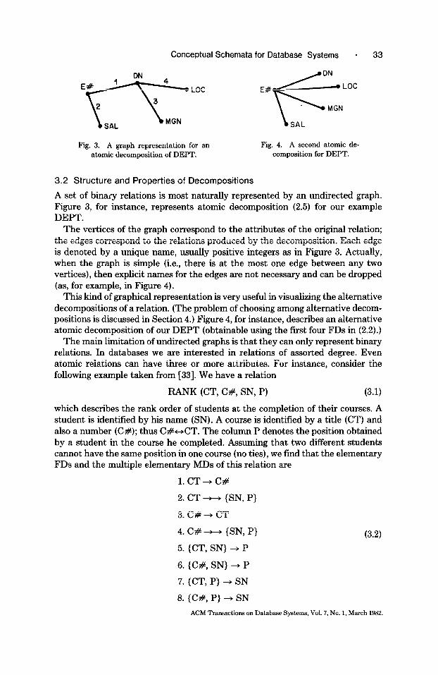
Fig. 3. A graph representation for an atomic decomposition of DEPT.
Fig. 4. A second atomic de- composition for DEPT.
3.2 Structure and Properties of Decompositions
A set of binary relations is most naturally represented by an undirected graph. Figure 3, for instance, represents atomic decomposition (2.5) for our example DEPT.
The vertices of the graph correspond to the attributes of the original relation; the edges correspond to the relations produced by the decomposition. Each edge is denoted by a unique name, usually positive integers as in Figure 3. Actually, when the graph is simple (i.e., there is at the most one edge between any two vertices), then explicit names for the edges are not necessary and can be dropped (as, for example, in Figure 4).
This kind of graphical representation is very useful in visualizing the alternative decompositions of a relation. (The problem of choosing among alternative decom- positions is discussed in Section 4.) Figure 4, for instance, describes an alternative atomic decomposition of our DEPT (obtainable using the first four FDs in (2.2).)
The main limitation of undirected graphs is that they can only represent binary relations. In databases we are interested in relations of assorted degree. Even atomic relations can have three or more attributes. For instance, consider the following example taken from [33]. We have a relation
RANK (CT, C#, SN, P) (3.1)
which describes the rank order of students at the completion of their courses. A student is identified by his name (SN). A course is identified by a title (CT) and also a number (C#); thus C#-CT. The column P denotes the position obtained by a student in the course he completed. Assuming that two different students cannot have the same position in one course (no ties), we find that the elementary FDs and the multiple elementary MDs of this relation are
l.CT+C#
2. CT - (SN, P}
3.C#+CT
4. C# ++ {SN, P}
5. {CT, SN} + P
6. {C#, SN} + P
7. {CT, P} + SN
8. (C#, P} + SN
(3.2)
ACM Transactions on Database Systems, Vol. 7, No. 1, March 1982.

34 * C. Zaniolo and M. A. Melkanoff
Fig. 5. The hypergraph of a first atomic decomposition of
RANK.
Fig. 6. The hypergraph of a second atomic decomposition of RANK.
Decomposing according to the multiple elementary MDs listed above, we obtain two atomic decompositions:
I’ {
1. RANK(C#, SN, P) 2. RANK(CT, C#)
II
I
1. RANK(CT, SN, P) * 2. RANK(CT, C#)
To represent decompositions such as these, where we have subrelations of degree higher than 2, we use the graphical conventions currently adopted to represent hypergraphs. Hypergraphs supply a natural generalization to the concept of undirected graphs. In this paper we review only a few very basic and very simple notions on hypergraphs. These notions will enable us to derive some important results on the structure of minimal atomic decompositions and its relationship to the MD structure of the original relation. The interested reader is referred to [7] for a more complete and general treatment of the properties of hypergraphs.
A hypergraph consists of vertices and edges just like an ordinary graph, but the edges of a hypergraph can contain one or more vertices. Edges with two vertices are represented by a line connecting these vertices just as in a conventional graph. An edge with three or more vertices is represented by a contour encircling its vertices. An edge with only one vertex is represented by a line which begins and ends at this vertex (a loop). The hypergraph of a set of relations is defined as one where each relation is represented by a distinct edge having as vertices the attributes of this relation. Thus the vertex set of the hypergraph of a set of relations Z is, by definition, equal to the union of the attribute-sets of all relations in X. Figures 3 and 4 represent the hypergraph of two decompositions of relation DEPT (when all edges contain exactly two vertices, the representations of hypergraphs and conventional graphs coincide). Figures 5 and 6 show the hyper- graphs of the two atomic decompositions of RANK previously given.
Next, we state two simple propositions, whose applications are discussed later.
PROPOSITION 3.1. The vertex set of the hypergraph of a decomposition of R (51) isS2.
Indeed, if we have a set of projections of R(G) such that the union of their attribute set is Q’ c a, then by taking their natural join we would obtain a relation R’(G?‘) which is not equal to R (s2).
In a hypergraph an edge is said to be minimal if it does not contain any other edge. In the hypergraph of a decomposition Z, an edge contained in another edge denotes that a member of X is a subprojection of another member in Z. Thus, we have the following proposition.
ACM Transactions on Database Systems, Vol. 7, No. 1, March 1982.

Conceptual Schemata for Database Systems - 35
PROPOSITION 3.2. The hypergraph of a minimal decomposition of a relation contains only minimal edges.
We next discuss the very useful notion of connectivity for hypergraphs. Two edges of a hypergraph are said to be adjacent if they have one or more vertices in common. The connectivity relationship between the edges of a hypergraph is defined as follows:
1. An edge is connected to itself. 2. Two adjacent edges are connected. 3. Two edges connected to a common edge are connected.
Thusconnectivity is an equivalence relation which partitions the original hyper- graph into groups of connected edges; each group is called a connected component of the hypergraph. Two vertices of a hypergraph are connected if they belong to the same connected component of the hypergraph. A hypergraph which consists of one connected component is said to be connected. The hypergraphs considered in Figures 3-6 are connected. We have the following property:
PROPOSITION 3.3. If the hypergraph of a decomposition of R (s2) consists of r connected components with vertex sets aI, . . . , a,., then R(Q) - nR (Q,) x . . . x IIR(S&.).
Indeed, one can construct R (a) by joining the subrelations in each connected component first, and then take the Cartesian product of these joins.
Let H be a hypergraph with vertex set a. Given r C a we construct H’ from H, as follows:
1. Remove every edge whose vertices all belong to r. 2. Replace every other edge i with vertices Ai by an edge i with vertices Al, where
A: = Ai - r.
The hypergraph H’ so constructed will be called the subhypergraph of H after the removal of I’.
We can now prove an important theorem.
PROPOSITION 3.4. Let H be the hypergraph of a decomposition of R(Q) and HI be any connected component of the subhypergraph of H after the removal of r, where r C !J. If A 1 denotes the vertex set of HI, then I? ++ A1 in R (a).
PROOF. The proposition is trivially true if HI is the only connected component of our subhypergraph. Otherwise, let X be a decomposition of R (52). Let X1 be the subset of Z corresponding to the edges of HI (i.e., the set of those II R (Ai) of Z such that Ai = Ai - I? is an edge of HI). If Rl(Ql) and Rz(&) denote the natural join of the projections in X1 and in Xz = I: - X1, respectively, then R1(Ql) -R&&) = R(a). Thus (% rl S&)++ S& in R(a). Clearly, A1 and I’ are disjoint and A1 c %. Moreover, for every IIR(Ai) in X1, Ai c Al U r. Thus a1 C Al U r. Thus a1 - r = A,. Also, every lIR(Aj) in ZZ is disjoint from Al. Thus S& and A1 are disjoint. Thus S& n S& c I’. Therefore, since (a, n S&)-P+ S’&, then I’ ++ !&. From this, r ++ (& - r). Q.E.D.
ACM Tmmsactions on Database Systems, Vol. 7, No. 1, March 1982.

36 . C. Zaniolo and M. A. Melkanoff
1 4
LOC Fig. 7. The hypergraph of Figure 3 after removal of E# 0 vertex DN.
SAL MGN
When I’ is the empty set, Proposition 3.4 reduces to Proposition 3.3. Proposi- tions 3.3 and 3.4 establish important relationships between the connectivity properties of a decomposition hypergraph of a relation and its MD structure.
If the hypergraph H with vertex set Q has k connected components and the subhypergraph of H after the removal of I’, where F C B, has more than k connected components, then r is called an articulation set for H. If F contains only one vertex, this is called an articulation vertex.
Thus, by inspecting the articulation set of a decomposition hypergraph, one immediately infers that certain MDs hold in the original relation. Take Figure 3, for instance. The attribute DN is an articulation vertex whose removal breaks up the original hypergraph into three connected components, as shown in Figure 7. (As we described previously, loops are used to represent edges with only one vertex.) In Figure 7, we have three connected components with vertices {E#, SAL}, {LOC), and {MGN).
Thus by Proposition 3.4 the following MDs hold in DEPT: DN ++ {E#, SAL}, DN ++ LOC, DN ++ MGN.
Let us now consider the application of these formal results to the problem of determining the minimality of a decomposition. If X is a decomposition of R (Cl!), then a projection lIR(Ai) in Z will be called superfhous ifE - {lIR(Ai)} is still a decomposition of R (a). An edge of a decomposition hypergraph will be called superfluous when it represents a superfluous subprojection. For instance, if we decompose RANK using first {CT, SN} + P and then C# -+ CT, we obtain the decomposition hypergraph
(1: {CT, SN, P}, 2: {C#, CT}, 3: {C#, SN}}.
Here edge 3 is superfluous, since edges 1 and 2 above already define a decompo- sition for RANK (see Figure 6). Thus a decomposition is minimal if it does not contain any superlluous subprojection (i.e., its hypergraph contains no superflu- ous edge). Now Proposition 3.1 prescribes that every edge of a decomposition hypergraph which contains some vertex not contained in any other edge cannot be superfluous. For example, in Figure 5, CT is only contained in edge 2; P is only contained in edge 1. Thus there is no superfluous edge, and we have a minimal atomic decomposition. By the same reasoning, Figure 6 also describes a minimal atomic decomposition for RANK.
Let us discuss the applications of Proposition 3.3. This states that given a relation R which is not the Cartesian product of two subprojections (i.e., there is no MD with an empty left side), then (1) the hypergraph of a decomposition of R must be connected, and (2) every edge whose removal will break the hypergraph in two or more connected components cannot be superfluous. For instance, the hypergraph of Figure 3 represents a decomposition for DEPT which is known to
ACM Transactions on Database Systems, Vol. 7, No. 1, March 1982

Conceptual Schemata for Database Systems 9 37
contain no MD with an empty left side. Now edges 2,3, and 4 each contain some vertex not contained by other edges; thus they are not superfluous. If we remove edge 1, the hypergraph is broken into two components; thus 1 cannot be super- fluous. Figure 3 thus represents a minimal atomic decomposition of DEPT. Therefore one finds that each edge in Figures 3-6 represents an atomic component for its relation. In passing, we note that these atomic components will survive even after some many-to-one relationships change into many-to-many. In DEPT, for instance, we have previously observed that if a department is associated with more than one location, then the FD, “DN + LOC” will not be valid any longer. The MD “DN ++ LOC” will hold instead. Even then, Figure 3 defines a minimal atomic decomposition and IIDEPT(DN, LOC) remains a valid atomic component for DEPT.
In conclusion, minimality of an atomic decomposition can usually be deter- mined by a simple visual inspection of its decomposition hypergraph. This seems to be true even when more complex decompositions are involved, such as those which we describe in the next section. These will require application of Proposi- tion 4.4.
Hypergraph models for a set of relations find other interesting applications, for example, in connection with the lossless join problem [32]. These are outside the scope of this paper.
4. SCHEMA DEFINITION AND DESIGN
We now present a novel approach to the definition and the design of graphical schemata for relational databases. In this approach we characterize the logical structure of the database in terms of elementary FDs and of atomic components of database relations. In conformity with the terminology used in [32] and [33], we refer to the atomic component structure and to the elementary FD structure of a relation as its A-structure and its Z-structure, respectively.
Our discussion will evolve as follows. In Section 4.1 it is shown that the combined definition of elementary FDs and atomic components provides an unambiguous characterization of a wide spectrum of logical relationships between database attributes. We also examine the rules which constrain the A-structure of a relation to its Z-structure. In Section 4.2 we present a simple and suggestive graph representation of the combined A- and Z-structure. In Section 4.3 we propose an algorithm to design the proper schema using the functional and multivalued dependencies of a relation. In Section 4.4 we discuss the various limitations of the proposed algorithm.
4.1 Atomic Components and Elementary FDs
We now examine the various configurations under which elementary FDs and atomic components combine and interact in a relation. Moreover, we show that by describing these configurations we can in fact characterize a wide spectrum of semantic relationships between database attributes, including the well-known one-to-one, one-to-many, and many-to-many archetypes. Instrumental in our developments is the concept of scope for an elementary FD [32]. If r + A is an elementary FD, then r U (A} is said to be its scope. Thus the scope of an elementary FD includes all the attributes pertaining to this FD.
ACM Tnmsactions on Database Systems, Vol. 7, No. 1, March 1982.

38 * C. Zaniolo and M. A. Melkanoff
Let us now consider the relationships described by atomic components and the elementary FDs contained therein. Note that an elementary FD can be contained in an atomic relation only if it has as scope the whole attribute set of this atomic relation. In a relation R, the presence of a binary relationship between its two attributes A and B is denoted by the presence of an atomic co.mponent IIR (A, B) and by the set of elementary FDs with scope {A, B}. If there are two FDs with scope {A, B}, namely, A + B and B + A, then this is a one-to-one relationship, also called a one-to-one correspondence. If there is only one such FD, say, A + B, then this is a many-to-one relationship from A to B. If no such FD exists, then this a many-to-many relationship. In our example RANK, for instance, we have a one-to-one correspondence between CT and C# (one course number per each course, and vice versa). Thus we find an atomic component IIRANK(CT, C #) containing the two elementary FDs: CT + C# and C# + CT. In DEPT we find several many-to-one relationships. For instance, many employees are associated with a given department; however, only one department is associated with any given employee. This relationship is described by the presence of an atomic component IIDEPT(E#, DN) containing one FD: E# + DN. For an example of a many-to-many relationship one could assume that, in DEPT, one department has more than one location (i.e., DN ++ LOC). As previously discussed, then DEPT still has IIDEPT(DN, LOC) as an atomic component. Now, however, there exists no elementary FD with scope {DN, LOC}. In summary, the combined definition of atomic components and elementary FDs is sufficient to describe the three basic types of relationships which occur between two attributes.
Let us consider now how atomic components and elementary FDs describe associations involving three or more attributes. For instance, consider the re- lationship between the three attributes C#, SN, and P in relation RANK, This relationship is denoted by the presence of the atomic component IIRANK (C#, SN, P) with FDs {C#, SN} + P and {C#, P} + SN. This kind of relationship (i.e., one involving three or more attributes) cannot be classified under one of the three basic binary types previously discussed. At best, it can be viewed as a structured collection of binary subrelations obtained by holding the remaining attributes constant. Thus, for a ternary relationship one can set each of three attributes constant and then describe the relationships between the remaining two attributes. For instance, our relationship between C#, SN, and P can be described as follows:
1. For a given C# there is a one-to-one correspondence between SN and P. 2. For a given SN there is a many-to-one relationship between C# and P. 3. For a given P there is a many-to-one relationship between C# and SN.
This way of looking at our relationship reminds us of the orthographic projec- tion technique which allows a three-dimensional object to be represented by three two-dimensional views. Unfortunately, as the order of a relationship grows, the number of bidimensional views required by this approach grows exponentially. However, these two-dimensional views can easily be derived given the elementary FDs (of an atomic component) whose number never exceeds the number of attributes in the atomic component.
ACM Transactions on Database Systems, Vol. 7, No. 1, March 1982.

Conceptual Schemata for Database Systems * 39
&+-.jb’. MO TU WD TH FR
8AM Gl Gl
9AM Gl Gl
10 AM G2 G2 G2 G2 G4
11 AM G3 G3 G4
12 AM Gl G3 Gl G3
Fig. 8. Weekly schedule of occupancy of a conference room.
Thus it appears that by supplying both the atomic components and the elementary FDs of a relation, one can represent unambiguously and concisely a wide spectrum of logical relationships between two or more attributes. Moreover, as we study further the possible configurations in which elementary FDs and atomic components combine and interact, we find that they are capable of describing relationships whose complex nature is hard to grasp by sheer intuition. We have just discussed the case in which the scope of an elementary FD and the attribute set of an atomic component coincide. Now we will analyze the contigu- rations where one properly contains the other. An elementary FD cannot have scope properly contained in an atomic component. However, there may exist atomic components with attribute sets properly contained in an elementary FD. To illustrate this situation with an example, consider the relation
WS(DAY, TIME, GROUP)
which describes the weekly schedule of occupancy of a conference room, where various groups meet. Typically, the content of such a relation is represented by a table such as that shown in Figure 8, where the time and day are respectively rows and columns, while the entries of the matrix are the names of the groups.
Only one group meets at any given day and time in the room. Thus {DAY, TIME} + GROUP. Assume also that a group must follow the same schedule for any day in which it uses the room. Under these conditions the set of hours assigned to a group does not depend upon the particular day in which the group uses the room. Thus GROUP --t, TIME and GROUP t, DAY. Indeed, the natural joint of Il WS(DAY, GROUP) and lIWS(TIME, GROUP) shown below returns the instance of relation (4.1) filled in as in Figure 8.
II WS(DAY, GROUP) II WS(TIME, GROUP) MO Gl 8AM Gl MO G2 9AM Gl TU G2 12 AM Gl TU G3 10 AM G2 WD Gl 11 AM G3 WD G2 12 AM G3 TH G2 10 AM G4 TH G3 11AM G4 FR G4
ACM Transactions on Database Systems, Vol. 7, No. 1, March 1982.

40 * C. Zaniolo and M. A. Melkanoff
Thus, if one looks at relation WS, from the viewpoint of the elementary FD “{DAY, TIME} + GROUP” he may regard it as an indivisible logical association between these three attributes. According to its atomic components this is not an indivisible binary association, but rather it consists of two binary relationships. Other interesting examples of relations having a similar kind of twofold logical structure are given in [3, 321. These present examples of relations characterized by elementary FDs of nested scope.
Since we have an atomic component II R (A) where A is not the scope of any elementary FD, and we can also have an elementary FD with scope A where II R (A) is not an atomic component, then it is clear that the atomic component structure of a relation (the A-structure) and its elementary FD structure (the Z- structure) are in many respects distinct and independent. However, their inde- pendence is restricted by important limitations, which result from the following theorems:
PROPOSITION 4.1. The left side of any nontrivial MD of R (L?) contains the right side attribute of any elementary FD of scope 52.
PROOF. If (52 - {A}) + A is the elementary FD and P t, A is the nontrivial MD, then we need to prove that A E I. Assume by contradiction that A fZ I’. Then either A E A or A E A = R - (I’ U A). If A E A by complementation and augmentation, one obtains: (F U (A - {A})) -++ A. But since F --t) A is not trivial, (I U (A - {A})) = ((P U A) - {A}) c (a - {A}). Thus (B - {A}) -A is not elementary, and that is a contradiction since we know that the counterpart of an elementary FD is elementary [33]. By the same reasoning, we find that A cannot belong to A. Thus, A E r. Q.E.D.
In our previous relation WS, for instance, we had {DAY, TIME} + GROUP while GROUP - DAY and GROUP --w TIME.
PROPOSITION 4.2. An n-ary relation R(Q) which contains at least n - 1 elementary FDs with scope Q is atomic.
PROOF. If P +4 A is a MD of R, then according to Proposition 4.1 ( F ] 2 n - 1. Thus, I -++ A is trivial.
The following theorem establishes an interesting relationship between elemen- tary FDs and atomic components (defined in Section 3.1 as the members of some minimal atomic decomposition).
PROPOSITION 4.3. If R(Q) contains some elementary FD with scope A and II R (A) is atomic, then II R (A) is an atomic component for R.
PROOF. If (A - {A}) + A is one of the elementary FDs with scope A, then R is decomposable into the pair RR(A) and IIR(Q - {A} ). Moreover, IIR (B - {A}) may be further decomposable, say, in a set of atomic relations Z. II R (A) is atomic by assumption. Thus Z U (II R (A)} is an atomic decomposition of R(n), although it need not be minimal. A minimal atomic decomposition for R (52) can be obtained by removing all superfluous relations from Z U {II R (A)}. However, this operation cannot remove II R (A) since no relation in Z contains attribute A. Thus Il R (A) remains as a component of the resulting minimal atomic decomposition. Q.E.D.
ACM Transactions on Database Systems, Vol. 7, No. 1, March 1982.

Conceptual Schemata for Database Systems * 41
Thus we have an important corollary which supplies the formal basis to our combined representations of A- and Z-structures:
PROPOSITION 4.4. If R(G) contains n elementary FDs with common scope L G 0 and n L 1 A 1 - 1, then II R (A) is an atomic component of R (a).
Thus if R has an elementary FD with scope {A, B}, then it also has an atomic component IIR (A, B); if R has at least two elementary FDs with scope {A, B, C), then it has an atomic component Il R (A, B, C), etc.
4.2 CAZ-Graphs
We propose that atomic components and elementary FDs should be used as the primitives for schema definition. Thus a schema for a relation R consists of the pair (ACOVER, ZCOVER), where
ACOVER denotes a set of atomic components of R, which constitutes a minimal decomposition for this relation, and
ZCOVER denotes a set of elementary FDs of R which constitutes a minimal cover for the FDs of this relation.
These two sets, however, cannot be selected independently. Instead, they must satisfy the mutual constraint, dictated by the admissibility condition [33]. This ensures that atomic components and elementary FDs are properly combined to represent the various relationships among attributes, as per the examples in the previous section. This condition also supplies the basis for the graphical repre- sentation of schemata and for the schema design algorithm which will be discussed in this and in the following sections. A pair (ACOVER, ZCOVER) will be called admissible when it has the following properties:
(i) If ZCOVER contains an elementary FD with scope A, then it also includes every elementary FD of R with scope A. Moreover, if II R (A) is atomic, then A is also contained in ACOVER (by Proposition 4.3 this is an atomic component for R ).
(ii) If, moreover, ACOVER contains A, then every elementary FD of R with scope A is included in ZCOVER.
We suggest that the sets ACOVER, ZCOVER, combined under the admissi- bility condition, can be used as a conceptual database schema. Figure 9 gives such a schema for our relation RANK (in the next section we show that this is in fact a good schema for our relation).
For convenience we have introduced an index (called LABEL) which uniquely identifies subsets of attributes; the subset of attributes identified by label i will be denoted hi.
We now introduce a graph representation of our schema. This will be called a combined A- and Z-graph or, for short, a CAZ-graph. The CAZ-graph, which represents the schema of a relation, has as vertices the attributes of this relation. Every arc of the graph has a label attached. An arc can either be of type one-to- one or type many-to-one, or type many-to-many. The graph representation of a schema (ACOVER, ZCOVER) is constructed as follows (Direct Mapping):
1. One-to-one arcs: There is a one-to-one arc labeled i between vertices A and B if ZCOVER contains two FDs with common scope Ai and with right sides A
ACM Transactions on Database Systems, Vol. 7, No. 1, March 1982.

42 * C. Zaniolo and M. A. Melkanoff
LABEL ACOVER ZC!OV+?SR -~
1 (C#, SN} + P Fig. 9. A schema for RANK.
(C#, P, SN) (C#, P) 4 SN
C# -+ CT CT --( C#
and B, respectively. This arc will be represented as follows:
A*: i
:*B
2. Many-to-one-arcs: There is a many-to-one arc labeled i between A and B if the following conditions are both satisfied:
(a) ZCOVER contains an FD of scope Ai whose left side contains A and whose right side is B. (Thus Ai contains both A and B.)
(b) There is no one-to-one edge with label i between A and B.
This arc will be represented as follows:
We shall say that this arc is leading into B.
3. Many-to-many arcs: There is a many-to-many arc labeled i between A and B if the following conditions are both satisfied:
(a) ACOVER contains Ai which contains both A and B. (b) There is no one-to-one or one-to-many arc with label i between A and B.
This arc is represented by a plain line as follows:
A. i
l B
The &U-graph corresponding to the pair (ACOVER, ZCOVER) of Figure 9 is given in Figure 10.
We now give the rules to derive the elementary FDs and the atomic components defined by a CAZ-graph G. If i is a label of some arc of G, then Gi will denote the subgraph of G defined by i; Gi is obtained by first removing from G all arcs not labeled i and then removing all the isolated vertices (i.e., those to which no arc is attached). For instance, if G is the graph of Figure 10, then Gz reduces to the one- to-one arc labeled 2 and the two end vertices of this arc. If in Gi there is an arc between every two vertices, then Gi is called a clique. Thus the direction of the arcs is immaterial in the definition of the cliques of a graph. Then the set of elementary FDs, ZCOVER, and the set of atomic components, ACOVER, defined by the CAZ-graph G can be constructed as follows.
Inverse Mapping. For every label i of G consider Gi, with vertex set Ai, and
(a) if Gi is a clique, then enter & in ACOVER ; (b) if B is a vertex of Gi connected to every other vertex of Gi by a one-to-one z+.rc
or by a many-to-one-arc leading into B, then enter (Ai - {B)) + B in ZCOVER.
ACM Transactions on Database Systems, Vol. 7, No. 1, March 1982.
Conceptual Schemata for Database Systems l 43
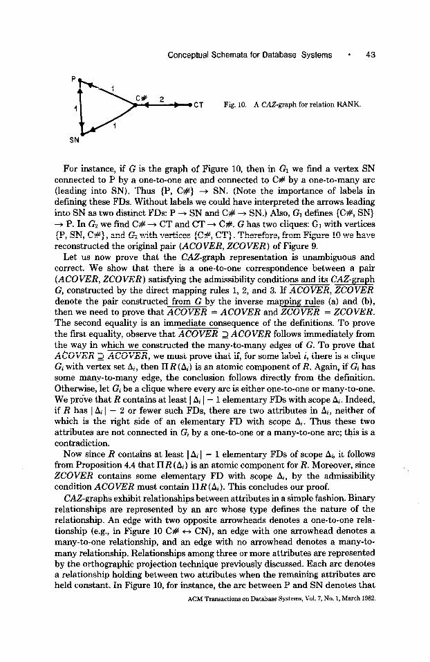
P 1
C# 2 4
D--
CT Fig. 10. A CA&graph for relation RANK.
I
SN
For instance, if G is the graph of Figure 10, then in G1 we find a vertex SN connected to P by a one-to-one arc and connected to C# by a one-to-many arc (leading into SN). Thus {P, C#} + SN. (Note the importance of labels in defining these FDs. Without labels we could have interpreted the arrows leading into SN as two distinct FDs: P + SN and C# + SN.) Also, G1 defines {C#, SN} + P. In Gz we find C# + CT and CT + C#. G has two cliques: G1 with vertices {P, SN, C#} , and Gz with vertices {C#, CT}. Therefore, from Figure 10 we have reconstructed the original pair (ACOVER, ZCOVER) of Figure 9.
Let us now prove that the CAZ-graph representation is unambiguous and correct. We show that there is a one-to-one correspondence between a pair (ACOVER, ZCOVER) satisfying the admissibility conditions and its CAZ-graph G, constructed by the direct mapping rules 1, 2, and 3. If ACOVER, ZCOVER denote the pair constructed from G by the inverse mapping rules (a) and (b), then we need to prove that ACOVER = ACOVER and ZCOVER = ZCOVER. The second equality is an immediate consequence of the definitions. To prove the first equality, observe that ACOVER 2 ACOVER follows immediately from the way in which we constructed the many-to-many edges of G. To prove that ACOVER 2 ACOVER, we must prove that if, for some label i, there is a clique Gi with vertex set Ai, then II R (Ai) is an atomic component of R. Again, if Gi has some many-to-many edge, the conclusion follows directly from the definition. Otherwise, let Gi be a clique where every arc is either one-to-one or many-to-one. We prove that R contains at least 1 Ai I- 1 elementary FDs with scope Pi. Indeed, if R has 1 Ai 1 - 2 or fewer such FDs, there are two attributes in Pi, neither of which is the right side of an elementary FD with scope Pi. Thus these two attributes are not connected in Gi by a one-to-one or a many-to-one arc; this is a contradiction.
NOW since R contains at least 1 Ai I - 1 elementary FDs of scope Pi, it follows from Proposition 4.4 that II R (Ai) is an atomic component for R. Moreover, since ZCOVER contains some elementary FD with scope A\i, by the admissibility condition ACOVER must contain II R (Ai). This concludes our proof.
CAZ-graphs exhibit relationships between attributes in a simple fashion. Binary relationships are represented by an arc whose type defines the nature of the relationship. An edge with two opposite arrowheads denotes a one-to-one rela- tionship (e.g., in Figure 10 C# c, CN), an edge with one arrowhead denotes a many-to-one relationship, and an edge with no arrowhead denotes a many-to- many relationship. Relationships among three or more attributes are represented by the orthographic projection technique previously discussed. Each arc denotes a relationship holding between two attributes when the remaining attributes are held constant. In Figure 10, for instance, the arc between P and SN denotes that
ACM Transactions on Database System, Vol. 7, NO. 1, March 1982

44 * C. Zaniolo and M. A. Melkanoff
TIME DAY
2 3
Fig. 11. A CAZ-graph representing relation WS.
a one-to-one correspondence exists between P and SN, when C# is held constant. The arc between C# and P denotes a many-to-one relationship with SN constant, and the arc between C# and SN denotes a many-to-one relationship with P constant.
CAZgraphs allow us to represent unambiguously complex relationships such as that involving elementary FDs of nonatomic scope. For instance, a CA.5graph representing the structure of our relation WS is given in Figure 11.
4.3 Schema Design
We now present a formal procedure for schema design using the functional and multivalued dependencies of a relation. The objective of this procedure is to produce an admissible pair (ACOVER, ZCOVER) which preserves the informa- tion of the original relation in terms of both content and structure, and represents it with minimal redundancy. This procedure consists of two steps:
1. a decomposition step which produces the admissible (ACOVER, ZCOVER) where ZCOVER is the minimal cover for the FDs of the given relation, and
2. a verification step to verify the minimality of the atomic decomposition ACOVER.
Next, we discuss the decomposition step. The verification step will be discussed later. The algorithm to perform the decomposition step was presented in [33]. This algorithm basically consists of a recursive procedure which operates as follows. Say that lI R (a) is the relation at hand with a set P of elementary FDs and a set (% of multiple elementary MDs; also let FO be the set of elementary FDs in P having LZ as scope. Then FO is added to ZCOVER and, if IIR(Q) is atomic (i.e., G,,, is empty), then IIR (a) is entered in ACOVER and the procedure is completed. If Il R (a) is not atomic, then (?m is searched for an elementary MD which ensures preservation of structural information. Once such an MD, say, P * A, is found, then II R (62) is decomposed into IIR (P U A) and lI R (52 - A). Next these two subrelations are decomposed in turn.
As discussed in [33], the MD “P +-+ 8” ensures preservation of structural information if the following two conditions are satisfied:
(R U Fz)+ > (P- Fo) (4.1)
(GF u GII U GA+ 2 l&z (4.2)
where
R and FL! denote the FDs in P whose scope is contained in (I’ U A) and (a - A), respectively.
GF denotes the MD counterparts of the FDs of I;i,
ACM Transactions on Database Systems, Vol. 7, No. 1, March 1982.

Conceptual Schemata for Database Systems * 45
SN
Fig. 12. The CM-graph for DEPT. ‘Fig. 13. A second CAZ-graph for RANK.
Gn and GZZ denote the MDs of G,,, having right sides disjoint from P, and left sides contained, respectively, in (P U A) and (0 - A).
Conditions (4.1) and (4.2) ensure that the FDs and the MDs of the initial relation are derivable from the dependencies of the resulting decomposition [33].
Before this recursive procedure is applied to the given relation, the sets ACOVER and ZCOVER are set to empty. Once the procedure completes, ACOVER and ZCOVER contain, respectively, a set of atomic subprojections of a given relation and a set of elementary FDs which satisfy the admissibility condition. In [33] we prove that ZCOVER so obtained constitutes a minimal couer for the FDs of R. While ZCOVER alone preserves and minimally represents the Z-structure of the initial relation, its A-structure is captured by ACOVER and ZCOVk’R combined.
Efficient algorithms to verify conditions (4.1) and (4.2) can be found in [4] and [3], respectively. An algorithm for deriving the multiple elementary MDs in projections of a given relation was presented in [33].
Application of this decomposition algorithm to our example DEPT produces the CAZ-graph of Figure 12.
As one can easily verify, the result of the decomposition of DEPT does not depend on the order in which the multiple elementary MDs in (2.2) are tested for compliance with conditions (4.1) and (4.2) and then used in the decomposition. However, if one decomposes RANK, he will obtain the graph of Figure 10 or that of Figure 13, depending on whether CT + C# or C# + CT is considered first. The fact that there exist two solutions is a logical consequence of the one-to-one correspondence existing between CT and C#. Clearly, either graph supplies an acceptable schema and both contain the same information.
The purpose of the second step of our design procedure is to verify the minimality of the atomic decomposition, ACOVER, provided by the first step. The use of only multiple elementary MDs in the decomposition supplies an extremely effective heuristic toward ensuring this minimality. To convince oneself of this, one could decompose RANK using a single elementary MD instead, for example, the counterparts of the elementary FDs 5,6, and 7 in (3.2), and obtain a clearly nonminimal decomposition. Nevertheless, there is no formal assurance that the decomposition step produces a minimal atomic decomposition. Actually, we know of a counterexample where a decomposition obtained using multiple elementary MDs is not minimal. This example, however, involves subrelations which are losslessly decomposable into three projections but not into two projec- tions. As we know, the semantic constraints obeyed by these relations cannot be
ACM Transactions on Database Systems, Vol. 7, No. 1, March 1982.

46 * C. Zaniolo and M. A. Melkanoff
modeled by MDs [23]. Whether minimality can be violated for decomposition of relations which only obey constraints expressible in terms of FDs and MDs is still an open problem.
Say, therefore, that our conservative designer wants to verify the minimality of the atomic decomposition Z produced by the first step of the design procedure. I: is minimal if it does not contain any superfluous relation. We know that the following members of I: cannot be superfluous: (1) those which contain some attribute not appearing in any other member of Z and, in the absence of MDs, with an empty left side; (2) those whose removal would break the connectivity of the associated hypergraph. For the examples we have considered so far these two rules were sufficient to infer minimality. In more complex examples, for example, the one which we consider next, some subrelation which could not be decided to be nonsuperfluous by the previous two rules could remain. Then for each such subrelation, say, IIR (A) in Z, one can use the algorithm presented in [l] to decide whether Z - {R(A)} has the lossless join property. In the presence of MDs, however, this algorithm may run in exponential time. A second approach is to use Proposition 3.4, as we are now going to illustrate with the help of an example taken from [33]. The attributes of interest are as follows:
LIC: MAKE: MODEL: YEAR: VALUE: OWNER
DRVL: VIOL: DATE:
license numbers of motor vehicles; manufacturers of motor vehicles; models of vehicles; the year in which the vehicle was manufactured; the current value of the vehicle; the unique identifier of a person (for simplicity, we give only the family name; in reality, a composite ID which includes the fast name, birth date, and iocation, etc., may be needed); the driving license numbers; the code numbers for traffic violations: month, day, and year of violation.
The following information is required:
1. the make, model, and year of any licensed vehicle; 2. the current (blue book) value of a given type of vehicle; 3. the legal owner of a given vehicle; 4. the driving license number of a given person (and the person having a certain
license number); 5. the traffic violation history of any driver; the records consist of pairs: violation
code and date of warrant.
Then we have a relation:
DMV (LIC, MAKE, MODEL, YEAR, VALUE, OWNER, DRVL, VIOL, DATE),
with elementary FDs and multiple elementary MDs:
Dl: LIC + MAKE D2: LIC + YEAR D3: LIC + MODEL D4: LIC + VALUE
ACM Transactions on Database Systems, Vol. 7, No. 1, March 1982.
Conceptual Schemata for Database Systems * 47
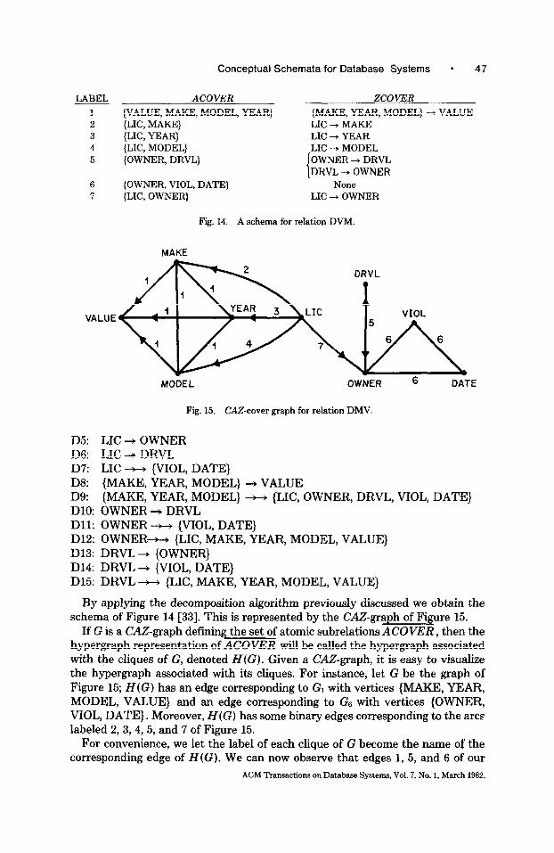
LABEL ACOVER
1 (VALUE, MAKE, MODEL, YEAR) 2 {LIC, MAKE) 3 (LIC, YEAR} 4 (LIC, MODEL] 5 (OWNER, DRVL}
6 {OWNER, VIOL, DATE) 7 {LIC, OWNER}
ZCOVER
{MAKE, YEAR, MODEL) -) VALUE LIC + MAKE LIC + YEAR LIC -+ MODEL OWNER + DRVL DRVL --f OWNER
None LIC + OWNER
Fig. 14. A schema for relation DVM.
MAKE
DRVL l
VALUE VIOL
MODEL OWNER 6 DATE
Fig. 15. CAZ-cover graph for relation DMV.
D5: LIC + OWNER D6: LIC -+ DRVL D7: LIC - {VIOL, DATE} D8: {MAKE, YEAR, MODEL} + VALUE D9: {MAKE, YEAR, MODEL} --w {LX, OWNER, DRVL, VIOL, DATE} DlO: OWNER + DRVL Dll: OWNER * {VIOL, DATE} D12: OWNER-H {LIC, MAKE, YEAR, MODEL, VALUE} D13: DRVL + {OWNER} D14: DRVL + {VIOL, DATE} D15: DRVL * {LIC, MAKE, YEAR, MODEL, VALUE}
By applying the decomposition algorithm previously discussed we obtain the schema of Figure 14 [33]. This is represented by the CAZ-graph of Figure 15.
If G is a CAZ-graph defining the set of atomic subrelations ACOVER, then the hypergraph representation of ACOVER will be called the hypergraph associated with the cliques of G, denoted H(G). Given a CA&graph, it is easy to visualize the hypergraph associated with its cliques. For instance, let G be the graph of Figure 15; H(G) has an edge corresponding to G1 with vertices {MAKE, YEAR, MODEL, VALUE} and an edge corresponding to GS with vertices {OWNER, VIOL, DATE}. Moreover, H(G) has some binary edges corresponding to the arcs labeled 2, 3,4,5, and 7 of Figure 15.
For convenience, we let the label of each clique of G become the name of the corresponding edge of H(G). We can now observe that edges 1, 5, and 6 of our
ACM Transactions on Database Systems, Vol. 7, No. 1, March 1982.

48 l C. Zaniolo and M. A. Melkanoff
H(G) are not superfluous since they contain some vertex not included in any other edge. Edge 7 cannot be superfluous since its removal would break the connectivity of the hypergraph. The question whether edges 2, 3, and 4 are superfluous can be resolved using Proposition 3.4. Assume that we remove edge 2. Then {YEAR, MODEL} becomes an articulation set for the hypergraph so obtained; this is broken by the removal of YEAR and MODEL into two connected components with vertices {MAKE, VALUE} and (LIC, OWNER, DRVL, VIOL, DATE}. Thus if IIDMV(LIC, MAKE) is superfluous in our decomposition, then, by Proposition 3.4, {YEAR, MODEL} t, {MAKE, VALUE} in DMV. But since such an MD does not hold in DMV, IIDMV(LIC, MAKE) cannot be superfluous. By analogy, one derives the fact that edges 3 and 4 cannot be superfluous. Therefore, even in this more complex example we were able to verify the minimality of our atomic decomposition by direct inspection of the connec- tivity properties of the associated hypergraph; we found no need to resort to the algorithm presented in [l].
Let us see how the dependency structure of a relation is preserved and represented by its CAZ-graph. For FDs the situation is clear. The set ZCOVER defined by the graph supplies a minimal cover for the FDs of the whole relation. For MDs the situation is more complex; it involves both sets ACOVER and ZCOVER defined by the graph. A first group of MDs consists of those derivable as the counterparts of FDs in ZCOVER. A second group of MDs is derivable from the connectivity properties of the graph, using Proposition 3.4. In the case of DMV, for instance, the two elementary MDs
Dll: OWNER - {VIOL, DATE) D12: OWNER - {LIC, MAKE, YEAR, MODEL,. VALUE}
can be derived from the graph of Figure 15 by simply observing that the removal of OWNER breaks the hypergraph associated with its cliques in three connected components, with vertices {VIOL, DATE}, {LIC, MAKE, YEAR, MODEL, VALUE}, and {DRVL} . Thus, Proposition 3.4 produces the desired conclusion. A third group of MDs is derivable from the MDs of the first two groups by using the MD inference rules [6].
D7: LIC t-, {VIOL, DATE} and D14: DRVL - {VIOL, DATE}
are derivable by composing, respectively, LIC +-+ OWNER and DRVL - OWNER with Dll.
4.4 Discussion
A recent survey [5] has exposed three basic principles supplying a common conceptual basis to the formal approaches to schema design proposed so far. These are as follows:
1. the principle of separation; 2. the principle of representation; 3. the principle of minimal redundancy.
In spite of this common conceptual basis, different works on schema design have used different formulation of these principles and pursued them to a different ACM Transactions on Database Systems, Vol. 7, No. 1, March 1982.

Conceptual Schemata for Database Systems * 49
degree. Thus we now assess the performance of our approach in the framework of these principles.
The principle of separation presides at the choice of “good” primitives for schemata. Certain relationships should not be represented together by a “big” relation but should be separated and represented independently by smaller relations. However, while everyone agrees that “small is good,” the issue “How small is good enough?” is somewhat controversial. A measure of this controversy is supplied by the large number of normal forms which are at present roaming the field. In our approach we have pursued the principle of separation to an extreme degree by ensuring that independent relationships are always represented by separate (atomic) relations. Thus, we decompose relations into finer granules than the normal form approach would: while atomic components are always fourth normal form, the reverse is not true. The admissibility copdition is instrumental in implementing this separation principle. To illustrate this point, assume that we represent our previous example RANK by a schema which does not satisfy the admissibility condition: assume that in ZCOVER of Figure 9 we replace {C#, SN} --, P by {CT, SN} + P. No loss of information has thus occurred since our old ZCOVER and the new ZCOVER have the same FD closure. After such a change, however, the schema represents the relationship between {C#, P, SN} in a less natural and less direct fashion. Indeed, to understand that for a constant C# there is a one-to-one correspondence between SN and P, one needs to look at a fourth attribute, CT, and, after finding which FDs hold in this larger context, derive the desired conclusion by transitivity. Thus the admissibility condition ensures that the representation of certain basic relationships is complete and self-contained, so that they can be treated indepen- dently from the context in which they appear. The benefits accrued by using the admissibility condition in the design of third normal form relations are discussed in [33].
In the framework of the decomposition approach the principle of representation prescribes that the final schema represents the same information as the original relations did. Since we have assumed that these relations with their dependencies completely describe the logical relationships of interest, the principle of represen- tation becomes an immediate consequence of the complete relatability principle discussed in the introduction.
We have applied the representation principle with rigor by requiring that both content and structure be preserved in the decomposition. Content preservation has been ensured as per the lossless join concept described in [l]. Preservation of structural information has been ensured with respect to both FDs and MDs- thus in a more general context than the one discussed in [24] and [2]. As a result of this, the elementary FDs of the given relation are either represented by the resulting CAZ-graph or inferable from it by the FD inference rules. The MDs of the original relation are instead defined by the graph, either by being the counterpart of an FD, or by the connectivity property of the graph, or indirectly through the MD inference rules. Thus it is quite legitimate and natural to speak of the &U-graphs generated by our design procedure as a cover graph for the given relations.
The principle of minimal redundancy has been applied here with rigor also Our schema consists of a set of elementary FDs, ZCOVER, and of a set of atomic
ACM Transactions on Database Systems, Vol. 7, No. 1. March 1982.

50 * C. Zaniolo and M. A. Melkanoff
components, ACOVER. The ZCOVER generated by our decomposition algorithm was proved minimal in [33]; thus no smaller subset of it is a cover for the FDs of the initial relation. Moreover, the second step in the design procedure also guarantees the minimality of ACOVER: no proper subset of it can be joined back into the original relation. It must be noted here that since this minimality condition is applied to atomic relations, it becomes a more stringent requirement than it would be otherwise. To illustrate this point, we can consider a decompo- sition of DMV containing some nonatomic subrelations. Say, for instance, that we take the decomposition defined by the graph of Figure 15 and we replace IIDMV(LIC, MAKE), IIDMV(LIC, YEAR), and IIDMV(LIC, MODEL) by the pair
IIDMV(LIC, MAKE, YEAR) (4.3) IIDMV(LIC, YEAR, MODEL). (4.4)
This new decomposition, consisting of the two projections above and of those defined by the cliques labeled 1, 7, 5, and 6 of Figure 15, is still minimal, as one can easily verify using Proposition 3.4. Yet in this minimal decomposition there is a significant amount of redundancy since the binary relationship between LIC and YEAR is represented in both (4.3) and (4.4).
Thus our design procedure realizes a very high standard for all three basic principles which are generally considered important in schema design. As a result of this high standard, the schemata produced by this procedure are “good” schemata in every respect. In all examples we have considered the natural relationships of interest were captured and represented in a rather natural expressive, and nonambiguous fashion. Of course, a price had to be paid for pursuing such high standards. There exist relations for which all the previous objectives cannot be met and either the decomposition algorithm or the verifi- cation step will fail. The decomposition algorithm could fail because there exists no multiple elementary MD for which the complete relatability conditions (4.1) or (4.2) are satisfied. Then the designer would be forced to intervene and decide how to resolve the situation. In the large majority of cases we have considered, the design procedure we have presented completes automatically without designer intervention. Therefore, we had available for analysis only a few examples of plausible semantics for which the design procedure would fail. In these examples the source of the problem was not the decomposition algorithm itself, but rather the objective impossibility of finding a solution satisfying all the strict standards which had been set for separation, preservation, and minimal redundancy. One way to ensure that the procedure completes automatically in every case would be to relax some of these standards. For instance, some workers argue that decom- position into Boyce-Codd normal form or fourth normal form should be per- formed even when preservation of structural information cannot be obtained [13, 151. On the contrary, a weaker statement of minimal redundancy is accepted in [8] for the purpose of obtaining third normal form relations. Here, instead, we decided to follow a different approach: the basic principles for a “good” design were strictly enforced, and we accepted the fact that on occasion all these principles cannot be met and a more direct intervention is required by the
ACM Transactions on Database Systems, Vol. 7, No. 1, March 1982.

Conceptual Schemata for Database Systems * 51
designer. This discipline offers two significant advantages. First, it ensures that schemata automatically generated by the design procedure are sound and well behaved by the strictest standards of good design principles. Our experience suggests that the great majority of real-life examples are still handled automati- cally. A second advantage is that those infrequent situations which are recalci- trant to the application of these “good” design principles are singled out, and the designer’s attention is drawn to them. As a result of a deeper look, the designer may recognize some peculiarities with the relation at hand. Our experience shows that these may be caused by some particular constraints between the relationships represented or possibly by a poor choice of the initial relation which was intended to represent them. Thus a halt in the decomposition procedure will supply some useful feedback to the designer and stimulate needed corrections. To illustrate this point, one can consider a relation DICT(F, G, E) which supplies a dictionary of corresponding technical terms or concepts in French, German, and English [33]. Assuming that a concept can be described by multiple synonyms but no terms describe more than one concept, then every attribute in DICT is MD on every other attribute. It is easy to see that no decomposition which satisfies (4.2) exists, and the only good solution to this problem is to introduce a new column, say, C for concept, to identify the concept corresponding to a set of synonyms. Then the decomposition procedure operates successfully on the new augmented relation (yielding the schema of [33], Figure 2).
On the contrary, if the designer feels that his initial schema was well suited for his statement of intension, then he may proceed in the decomposition in the way he deems most appropriate for the case at hand. For instance, if condition (4.1) is not satisfied, he may decide to disregard some elementary FD and then choose a minimal decomposition which preserves the remaining ones, or he may decide to accept redundancy and decompose the relation into larger subprojections or into more than two subprojections to ensure that a cover for the FDs of the relation is preserved. In either case, however, it is clear that there will be some side constraints not embodied in the schema of which the designer better be aware.
In conclusion, we suggest that our approach supplies a reasonable compromise between the desire to have a formal algorithm for automatic schema design and the requirement that this algorithm in fact deliver a good schema for the application at hand according to some well-defined design criterion. Nevertheless, this is a topic which deserves further investigation. For instance, various exten- sions and improvements to the algorithm are proposed in [28].
When thinking of graphical schemata for databases, one normally envisions diagrams describing the whole database or at least substantial portions of it. Clearly, it is possible to describe a whole database by one CAZ-graph. To design this graph one could start from a “universal relation” which includes all the attributes and all the relationships of interest. While the “universal relation” is a useful analytical tool [5], representing every relationship of interest by one relation is certainly cumbersome and possibly unattainable [32]. Thus, a few relations of a reasonable size supply a more practical starting point. Then at the end of the design the CA&graphs of the various relations will be pasted together
ACM Transactions on Database Systems, Vol. 7, No. 1, March 1982.

52 * C. Zaniolo and M. A. Melkanoff
into one graph. If we assume that no interrelational dependency or redundancy occurs among the initial relations, then the CA&graph so constructed supplies a good schema according to the three design principles discussed in this section.
5. APPLICATIONS
5.1 E-R Diagrams
A useful correspondence can be established between CAZ-minimal cover graphs and the entity-relationship (E-R) diagrams which were developed by Chen as models for database definition and design [9, lo]. E-R diagrams use two types of nodes: entity nodes depicted by rectangular boxes and relationship nodes depicted by diamond-shaped boxes. The correspondence between an E-R diagram and a CAZ-graph, G, can be established as follows: the entity nodes correspond to the vertices of G while the relationship nodes correspond to its labels. To each partial subgraph Gj, where j is a label of G, there corresponds in the E-R diagram a set of arcs connecting the relationship node j to the various vertices of Gj. If A is one of these nodes, then the arc connecting A with j in the E-R diagram is tagged “one” if,Gj has either a one-to-one or a one-to-many arc leading into A (i.e., if the arrowheads lead’into it); this arc is tagged “many” otherwise. In the diagrams, “one” is actually shown as “1” while “many” is shown as either “N” or ‘M” or “P”. The transformation of a CAZ-graph into an E-R diagram, and vice versa, is indeed very intuitive and easily understood from an example. The E-R diagram corresponding to the cover graph of Figure 15 is given in Figure 16. In this E-R diagram, each single attribute constitutes a separate entity. Thus, each diamond- shaped box defines an atomic component of our relation DMV. In other words, an atomic relationship exists beween the entities adjacent to this diamond. For instance, the diamond marked “1” denotes an atomic relationship between MAKE, YEAR, MODEL, and VALUE. Moreover, the tags of the arcs radiating from a diamond define the elementary FDs having as scope the set of attributes of the atomic relation denoted by the diamond. The tag “1” at an arc establishes that the entity at the end of this arc is FD on the remaining entities of the atomic relationship; moreover, this FD is elementary. For instance, the leftmost diamond in Figure 16 denotes an atomic relationship between the four attributes MAKE, YEAR, MODEL, and VALUE. The tag “1” at the end of the leftmost arc shows that there exists an elementary FD from the first three attributes to the fourth one. (By analogy with the notation used to denote FDs, therefore, one could use an arrowhead on the arc to denote an arc of type “one”; then arcs of type “many” would be left without arrowheads.) In summary, there exists a simple comespon- dence between E-R diagrams and CA.%graphs, inasmuch as they use the same primitives to represent relationships. These primitives are atomic components and elementary FDs, which, in turn, reexpress the structure of FDs and MDs of a relation. However, there are differences between CA&graphs and the E-R model which cannot be overlooked. These are discussed next.
A major aim of Chen’s work is to produce a general description of the database called the enterprise schema. Thus certain conceptual objects of general interest to the whole enterprise are identified and catalogued. These objects are called entities, and E-R diagrams are used to give an overall representation of the ACM Transactions on Database Systems, Vol. 7, No. 1, March 1982.

Conceptual Schemata for Database Systems * 53
1
P 1
N N
I
Fig. 16. The E-R diagram representation of the CAZ-graph of Figure 15.
relationships between the entities supported by the database system. The use of entities, by making the whole picture more succinct and suggestive, supplies a congenial interface to the management of the enterprise; in brief, it provides the means to achieve the main objectives of an enterprise schema. However, both the users in formulating their queries and data manipulation requests and the database implementor are concerned with a much finer level of detail: they are primarily concerned with attributes and their values. Thus the upper level entities are then redefined at a lower level as a collection of attributes.
Throughout this paper we have regarded each single attribute as a separate entity. The graph of Figure 16 is indeed the E-R diagram for our DMV study case where each attribute of interest is regarded as an entity. Nothing, however, restricts the designer from specifying that an entity correspond to a group of logically related attributes. For our DMV example, for instance, a designer might want to specify an entity called VEHICLE-TYPE consisting of four attributes; MAKE, YEAR, MODEL, and VALUE. The various concepts and results pre- sented in the previous sections regarding the dependency structure of a relation, its decomposition, and its representation by means of graphic schemata remain valid and are applicable in this new context as well, In the case at hand, for instance, one need only replace the four attributes MAKE, YEAR, MODEL, and VALUE by VEHICLE-TYPE in relation DMV. The combinations of the values
ACM Transactions on Database Systems, Vol. 7, No. 1, March 1982.

54 * C. Zaniolo and M. A. Melkanoff
VEHICLE-TYPE
Fig. 17. The E-R diagram for relation DMV after combining VALUE, MAKE, MODEL, YEAR into VEHICLE-TYPE.
of these four attributes constitute the values of VEHICLE-TYPE. Thus, one can proceed to determine the dependencies of the relation so obtained and then to decompose it into a minimal cover schema using the procedure described in the last section. The result of this process is described by the E-R diagram in Figure 17. The relationships A5, A6, and A7 of Figure 17 correspond to the ones marked, respectively, 5,6, and 7 in Figure 16. However, Al234 denotes a new relationship which has replaced those marked 1,2,3, and 4 in Figure 16.
A formal discipline is thus available for designing E-R models for databases: The designer starts from a database sample in tabular form. Next he must identify the entities of interest as aggregates of attributes of this relation and list the dependencies existing among these attributes. Finally, he will apply the design procedure given in the last section to obtain an E-R diagram representing the relationships between these entities. For instance, in [22] we discuss various choices of entities for our DMV example, and we give the corresponding E-R diagrams. This approach, therefore, allows the designer to select the aggregates he wants to use as entities. This is a reasonable policy since the question as to what constitutes an entity has a subjective answer. Some guidelines are, however, available to help the designer in his choice. For instance, in [17] it is suggested that entities should have a unique key attribute and at least one other attribute. Useful concepts on this issue can also be found in [29]. Finally, the work of [30] ACM Transactions on Database Systems, Vol. 7, No. 1, March 1982

Conceptual Schemata for Database Systems - 55
suggests that this problem can be attached in the framework of FDs and MDs. This is the very framework within which we have developed our decomposition algorithm.
E-R diagrams are also useful as a database design aid. Indeed, Chen describes how they supply a unified basis for the design of network and hierarchical schemata as well as relational ones. Thus, we have now a discipline whereby, given the functional and multivalued dependencies of a relation, a network schema implementation for it can be derived. This is certainly an encouraging result for anyone who believes that a common theoretical foundation exists for the database field.2 Because of their affinity with E-R diagrams, CA.%graphs can be used as a design aid as well. In [33], we show how a CA&over graph produced by the decomposition procedure of Section 4.3 can be turned into a 3NF schema using Bernstein’s algorithm [S]; we also illustrate how this approach may in fact result in the design of better 3NF schemata.
The E-R diagrams were informally introduced by means of examples and advocated as being particularly congenial to nonspecialists. We now find that they are amenable to a much more rigorous definition: they define the atomic relationships of the database and the elementary functional dependencies having as scope these relationships. These relationships span conceptual objects called entities which are specified by the database administrator as combinations of elementary attributes. The E-R model does not display every atomic relationship, but only a minimalset which defines a cover in a sense completely analogous to the minimal cover concept for CAZgraphs defined in the previous section. However, observe that, while the atomic relationships produced by the decom- position algorithm are inherently projections of the same relation, no such constraint needs to be assumed in an E-R diagram (or for that matter, in a CAZ- graph). Thus, for instance, in Figure 16, there could exist instances of OWNER which do not participate in some or all of relationships 5, 6, and 7. Then, the relationships of Figure 16 can be considered the projections of one relation only if this is allowed to contain null values [21].
The correspondence between CAZ-graphs and E-R diagrams exposes a problem area which is not discussed in Chen’s paper. This problem is caused by elementary FDs of nonatomic scope which were discussed at length in Section 4. (See, for example, relation WS where we have {TIME, DAY) + GROUP while GROUP - DAY and GROUP --f-, TIME.) In such cases it is not clear which relation- ships should be displayed in the E-R diagram. One solution is to ignore elementary FDs which are nonatomic in scope and to represent atomic relations only; vice versa, one could display the nonatomic elementary FDs by diamonds and neglect the finer relationships contained therein. Finally, one could display both the atomic relations and the nonatomic elementary FDs by diamonds in the E-R diagram. None of these three solutions is clearly superior to the others. Indeed, each presents some advantages and disadvantages and seems most reasonable, depending on individual cases [22]. Because of this problem and because E-R diagrams are not as close to the usual graphs as CAZ-graphs, we have used the latter in our formal development. Nevertheless, a practitioner could reasonably
* The use of dependencies in analyzing and improving E-R diagrams was also discussed in [26].
ACM Transactions on Database Systems, Vol. 7, No. 1, March 1982.

56 * C. Zaniolo and M. A. Melkanoff
adopt a more pragmatic view by observing that elementary FDs of nonatomic scope are rare in practice and could thus be treated on an individual basis. With this proviso E-R diagrams would probably be considered as attractive alternates to CAZ-graphs.
5.2 Conceptual Schemata
The graphs developed in this paper can be used as a conceptual schema in a database system architecture such as that proposed by the ANSI/X3/SPARC study group [31]. The conceptual schema for such a system supplies the central frame of reference. It also establishes the functional connections linking the various external schemata that supply a convenient environment for user appli- cations to the internal schema which is designed to optimize performance on typical queries and data manipulation requests. To provide data independence, the conceptual schema must define the logical structure of data independently of physical implementation. Current network or hierarchical schemata are designed to reflect not only the logical relationships among data, but also the expected usage of the data as seen by the database designer. Indeed, there are usually several possible hierarchical or network realizations of an E-R diagram. Moreover, the user may want to view the data as hierarchically organized in the external schema, although the data are actually organized into a plex structure. Thus the database systems should be capable of supporting multiple data models. A direct mapping between different models is a formidable problem, and it is even more difficult when there exists no one-to-one correspondence between the logical structure of data and the schema as in the previous cases. A more promising approach consists in using at the conceptual schema level a meta-model which is easily mapped into other models. Thus the mapping between the external and internal schema models is realized through an intermediate transformation into the metamodel. Because they are easy to transform into networks, hierarchies, and relations, E-R diagrams (or similar graphs) represent an obvious choice for the metamodel. However, since the system must translate data retrieval and manipulation of individual data fields, the conceptual schema requires a level of detail at which each attribute is visible. Thus diagrams such as that of Figure 16, which display the relationships between each single attribute, should be used. This solution suggests some obvious considerations regarding the relationships which should exist between the enterprise schema and the conceptual schema.
Since they are both used as a logical frame of reference for the enterprise, they should be, as far as possible, identical. Yet they must perform a different function. The former establishes the enterprise view of data, the latter links the external schema to the internal schema. The practical requirements dictated by their different roles could force undesirable differences upon them. On the other hand, the approach taken in this paper allows the two schemata to realize their individual goals along a very well-defined pattern. Both the enterprise schema and the conceptual schema are expressed by the same metamodel. The enterprise schema is only a summary of the conceptual schema obtained by grouping the attributes under categories called entities. Translation between the two schemata is accomplished by means of the shift operation between upper conceptual domain and lower conceptual domain described by Chen [lo]. ACM Transactions on Database Systems, Vol. 7, No. 1, March 1982.

Conceptual Schemata for Database Systems l 57
The database diagrams we have described represent a relational schema which is somewhat different from the one originally proposed by Codd. This is for a good reason: in Codd’s approach a set of relations of assorted degree defines both the database schema and the database content. The schema is defined by the headings of the relations where the keys are underlined, and the database content is defined by the rows of the tables. This combined framework constitutes one of the most attractive features of the relational approach. Yet when we consider a multilevel schema architecture, such as that of [31], we find that database content need not be materialized at the conceptual schema level. Thus the congeniality of tables as vehicle for representing the database content becomes a moot quality for a conceptual schema. Unambiguous and complete definition of the logical structure of data (complete relatability) is the main requirement at this level, and it appears that graphical models attain this objective more completely and concisely than a set of normal form relations with keys. In particular, CA&graphs are capable of defining both atomic relationships and elementary FDs. These are not always inferable from the underlining of keys in normalized relations (see [5] for a discussion of the problems presented in this area by the various normal forms). Furthermore, a higher degree of data independence results from the use of small modules as the building blocks of the conceptual schema. In our diagrams we have used atomic relationships which are the smallest logical granules avail- able. Thus, any change in one of these atomic relationships would only perturb the mapping to those external schemata which use that relationship. This is not true when third (or fourth) normal forms are used. Indeed, a change in any atomic relationship included in a relation (e.g., a change from many-to-one to many-to-many) would compromise the third normal form property and cause a change in the schema; then every relationship contained in a perturbed relation will also be affected. In conclusion, it appears that the diagrams discussed in this paper represent a reasonable usage of the relational model as the conceptual schema in an architectural framework such as that of [31]. This idea is explored even further in [32], where unnormalized relations are used at the external level, CA.5graphs are used at the conceptual level, and fourth normal form type of relations are used at the internal level. It is also shown there how a query reformulation mechanism can be used to support the mapping from the external schema into the conceptual schema and thenceforth into the internal schema.
6. CONCLUSIONS
This paper has described a formal approach to the definition and the design of conceptual database diagrams which are useful in designing various forms of schemata and, most important, in the role of conceptual schemata for a DBMS architecture as that proposed by [31].
A number of previous authors have independently recognized and advocated graphical representations of database relationships as a powerful, convenient, and implementation-independent vehicle for conceptual data definition. The contri- bution of this paper consists in establishing a constructive and rigorous connection between certain types of database diagrams and some formal constraints which are currently used to describe database relationships in the framework of the relational data model. The database diagrams discussed here include E-R
ACM Transactions on Database Systems, Vol. 7, No. 1, March 1982.

58 * C. Zaniolo and M. A. Melkanoff
diagrams and a newly introduced representation called a CAZ-graph. The rela- tional constraints considered include both functional and multivalued dependencies.
The formal basis of our graphical schemata has been a combined representation of the two basic structures underlying every database relation: the A-structure defined by the atomic components of the relation, and the Z-structure defined by the elementary FDs of the given relation. This paper has contributed to a better understanding of the properties and the mutual relationships of these two structures. We have analyzed the various configurations under which atomic components and elementary FDs can combine in a relation and shown how their joined representation can describe a wide spectrum of database relationships, of which the well-known one-to-one, one-to-many, and many-to-many constitute only a small subset. The basic properties of the minimal atomic decompositions of a relation have also been investigated; a simple correspondence was established between the topological properties of these decompositions and the MD structure of the relation. This correspondence was shown useful in verifying the minimality of the resulting decompositions.
The proper schema for a given relation must supply a complete but nonredun- dant representation of its combined A- and Z-structures; thus it consists of (1) a set of atomic components which form a minimal decomposition for the given relation, and (2) a minimal cover set of its elementary FDs. A formal procedure for schema design given the FDs and MDs of the relations was then presented. Its design objective is to ensure completeness of representation (complete relat- ability) with minimum redundancy. The basic decomposition steps of the design procedure were taken from [33], where they were shown to be useful for the design of third normal form schemata.
Graphical representations of our schemata in the form of CAZ-graphs and E-R diagrams were then defined and illustrated by a number of examples. Finally, we discussed the application of these diagrams as a design aid and as a conceptual schema.
REFERENCES
1. AHO, A.V., BEERI, C., AND ULLMAN, J. The theory of joins in relational databases. In Proc. 18th Ann. Symp. Foundations of Computer Science, Nov. 1977.
2. ARORA, A. K., AND CARLSON, C. R. The information preserving properties of relational database transformations. In Proc. 4th Int. Conf. Very Large Data Bases (West Berlin, Germany, Sept. 1978), pp. 352-359.
3. BEERI, C. On the membership problem for functional and multivalued dependencies in relational databases. ACM Truns. Database Syst. 5,3 (Sept. 1980), 241-259.
4. BEERI, C., AND BERNSTEIN P.A. Computational problems related to the design of normal form relational schemas, ACM Trans. Database Syst. 4, 1 (March 1979), 30-59.
5. BEERI, C., BERNSTEIN, P.A., AND GOODMAN, N. A sophisticate’s introduction to database normalization theory. In Proc. 4th Int. Conf. Very Large Data Bases (West Berlin, Germany, Sept. 1978), pp. 113-124.
6. BEERI, C., FAGIN, R., AND HOWARD, J.H. A complete axiomatization for functional and multi- valued dependencies in database relations. In Proc. ACM SIGMOD Int. Conf. Management of Data (Toronto, Canada, Aug. 3-5,1977), pp. 47-61.
7. BERGE, C. Graphs and Hypergruphs. North-Holland, Amsterdam, 1973. 8. BERNSTEIN, P.A. Synthesizing thiid normal form relations from functional dependencies. ACM
Trans. Database Syst. I,4 (Dec. 1976), 277-298.
ACM Transactions on Database Systems, Vol. 7, No. 1, March 1982.

Conceptual Schemata for Database Systems * 59
9. CHEN, P.P. The entity-relationship model-Toward a unified view of data. ACM Trans. Data- base Syst. I, 1 (March 1976), 9-36.
10. CHEN, P.P. The entity-relationship model-A basis for the enterprise view of data. In Proc. 1977 Nat. Computer Conf. (Dallas, Tex., June 1977).
11. CODD, E.F. Further normalization of the database relational model. Database Systems, Courant Computer Science Series, vol. 6, Prentice-Hall, Englewood Cliffs, N.J., 1972.
12. CODD, E.F. Recent investigations in relational database systems. In IFZP Conference Proceed- ings, North-Holland, Amsterdam, 1974, pp. 1017-1021.
13. DATE, C.J. An Introduction to Database Systems, 2nd ed. Addison-Wesley, Reading, Mass., 1977.
14. FAGIN, R. Multivalued dependencies and a new normal form for relational databases. ACM Trans. Database Syst. 2,3 (Sept. 1977), 262-278.
15. FAGIN, R. The decomposition versus the synthetic approach to relational database design. In Proc. 3rd Int. Conf. Very Large Data Bases (Tokyo, Japan, Oct. 1977), ACM, New York, 1977, pp. 441-446.
16. FALKENBERG, E. Concepts for modelling information. In Proc. ZFZP TC-2, Working Conference on ModelZing in Data Base Management Systems, G. Nijessen (Ed.) North-Holland, Amsterdam, 1976.
17. FLORY, A., AND KOULOUMIDJAN, J. A model and a method for logical database design. In Proc. 4th Conf. Very Large Data Bases (West Berlin, Germany, Sept. 1978), pp. 333-350.
18. HALL, P., OWLETT, J., AND TODD, S. Relations and entities. In Proc. IFIP TC-2, Working Conference on Modelling in Data Base Management Systems, G. Nijessen (Ed.), North-Holland, Amsterdam, 1976.
19. JOINT GUIDE AND SHARE DATABASE REQUIREMENT GROUP Requirements for a database management system. Nov. 1970. (Available from SHARE, Suite 750, 25 Broadway, New York, NY, 10904.)
20. KATZ, R.H. Database design and translation for multiple data models. Ph.D. thesis, Univ. California, Berkeley, 1980.
21. LIEN, Y.E. On the semantics of the entity-relationship data model. In Entity-Relationship Approach to Systems Analysis and Design, P. Chen (Ed.). North-Holland, Amsterdam, 1980.
22. MELKANOFF, M.A., AND ZANIOLO, C. Decomposition of relations and synthesis of entity-rela- tionship diagrams. In Entity-Relationship Approach to System Analysis and Design, P. Chen (Ed.). North-Holland, Amsterdam, 1980.
23. NICHOLAS, J.M. Mutual dependencies and some results on undecomposable relations. In Proc. 4th Int. Conf. Very Large Data Bases (West Berlin, Germany, Sept. 1978), pp. 360-367.
24. RISSANEN, J. Independent components of relations. ACM Trans. Database Syst. 2, 4 (Dec. 1977), 317-325.
25. Rousso~ou~os, N., AND MYLOPOULOS, J. Using semantic networks for database management. In Proc. Conf. Very Large Data Bases (Framingham, Mass., Sept. 1975), pp. 144-172.
26. SAKAY, H. On the optimization of the entity-relationship model. In Proc. 3rd USA-Japan Conf. (Oct. 1978), pp. 145-149.
27. SCHMID, H.A., AND SWENSON, J.R. On the semantics of the relational data model. In ACM SIGMOD Workshop Management of Data (San Jose, Calif., May 1975), pp. 211-223.
28. SILVA, M.A., AND MELKANOFF, M.A. Decomposition of universal relation schemas allowing interrelational dependencies. (Manuscript submitted for publication.)
29. SMITH, J.M., AND SMITH, D.C.P. Database abstractions: Aggregation. Commun. ACM 20, 6 (June 1977), 405-413.
30. SPYRATOS, N., AND BANCILHON, F. Name independence and database abstraction in the rela- tional model. In Proc. MFCS 78 Symp. (Zakopane, Poland, Sept. 1978).
31. TSICHRITZIS, D., AND KLuG, A. (Eds.) The ANSI/XWSPARC DBMS framework report of the study group on database management systems. Inf. Syst. 3,3 (1978).
32. ZANIOLO, C. Analysis and design of relational schemata for database systems. Ph.D. thesis, Computer Sci. Dep. Rep. UCLA-ENG-7669, UCLA, Los Angeles, Calif., July 1976.
33. ZANIOLO, C., AND MELKANOFF, M.A. On the design of relational database schemata. ACM Trans. Database Syst. 6, 1 (March 1981), l-47.
Received May 1979; revised February 1981; accepted February 1981
ACM Transactions on Database Systems, Vol. 7, No. 1, March 1982.