a guide for the nondestructive testing of non · pdf filessc-253 a guide for the...
TRANSCRIPT
.
..
SSC-253
.-.
A GUIDE FOR THE NONDESTRUCTIVE
TESTING OF NON-BUTT WELDS IN
COMMERCIAL SHIPS
PART ONE
This document has been approved forpublic release and sale; its
distribution is unlimited.
SHIP STRUCTURE COMMITTEE
1976
-. -- —
--
MEMBERAGENCIE5:
Un(ted States Coast Guard
Nav.1 Sea Systems Commond
MI IIIQry Seal(ft Command
Maritime Administration
American Bureau of Shlpplng
SHIP STRUCTURE COMMl~EEAN INTERAGENCY ADVISORY
COMMITTEE DEDICATED TO IMPROVINGTHE STRUCTURE OF SHIPS
ADDRES5CORRESPONDENCETO: .Secretary
Ship Structure Committee
U.S. Coast Guard Headquarters
Washington, D,C. 20590
SR-219
Most of the information on nondestructive tests (NDT) ofwelded steel joints given in specifications, handbooks, and guides arefor butt weld joints. However, there have and will be times when otherweld joint configurations are inspected. The Ship Structure Committee’de’cermined there was a need and initiated a project to develop a guideto aid in the proper application of various NDT methods to cover suchnon–butt welded joint configurations commonly used in ship and othermarine structures. This report is that guide. It does not setacceptance standards but does provide a meaningful way by which suchstandards may be applied.
To make the guide useful to production and inspectionpersonnel in shipyards, the technical support data was placed in aseparate report – SSC–254 – under the same title but as Part Two.
Comments and suggestions for additional research topics on
problem areas will be most welcome.
W. M. BenkertRear Admiral, U.S. Coast GuardChairman, Ship Structure Committee
,.—

SSC-253
A GUIDE FOR THE NONDESTRUCTIVE
TESTING OF NON-BUTT WELDS IN
COMMERCIAL SHIPSPART ONE
This document has been approved forpublic release and sale; its
distribution is unlimited.
SHIP STRUCTURE COMMITTEE
1976

MEMBERAGENCIES:
Umtcd Stotes Coast Guard
Navel 5ea Systems Command
Milltary Seol(ft Command
Maritime Administration
Amer(cun Buren. of Shippiog
SHIP STRUCTURE COMMITTEEAN INTERAGENCY ADVISORY
COMMITTEE DEDICATED TO IMPROVINGTHE STRUCTURE OF SHIPS
ADDRESSCORRE$PONDENCETO:Secretary
Ship Structure Committee
U.S. Coast Guord Headquarters
Washington, D.C. 20590
SR-219
Most of the information on nondestructive tests (NDT) ofwelded steel joints given in specifications, handbooks, and gutdes arefor butt weld joints. However, there have and will be times when otherweld joint configurations are inspected. The Ship Structure Cominittee’determined there was a need and initiated a project to develop a guideto aid in the proper application of various NDT methods to cover suchnon-butt welded joint configurations commonly used in ship and othermarine structures. This report is that guide. It does not setacceptance standards but does provide a meaningful way by which suchstandards may be applied.
To make the guide useful to production and inspectionpersonnel in shipyards, the technical support data was placed in aseparate report – SSC–254 – under the same title but as Part Two.
Comments and suggestionsproblem areas will be most welcome.
for additional research topics on
W’.M. BenkertRear Admiral, U.S. Coast GuardChairman, Ship Structure Committee

SSC-253
Final Report
on
Project SR-219, “Nondestructive Test (NDT) Guide forWelded Steel Joints”
A GUIDE FOR THE NONDESTRUCTIVE TESTING OF NON-BUTT
WELDS IN COMMERCIAL SHIPS
PART ONE
by
R. A. Youshaw and E. L. Criscuolo
Naval Surface Weapons Center
under
Department of the NavyNSWC Project NAVSHIP #00-0141
?’h-isdocument has been app~oved for public zwZ.easeand sale; itz distirihtion is unlimited.
U. S. Coast Guard HeadquartersWashington, D.C.
1976
ABSTRACT
This guide has been prepared to provide nondestructive tesb information
for application to all weld joints other than butt welds. It co~e~s
welds in the thickness range 1/2” to 2 1/2” and considers the five
basic inspection methods: Visual, Radiography, Ultrasonic, Magnetic
Particle, and Dye Penetrant.
It should be noted that most joints in commercial shipbuilding other
than butt welds are not nondestructively inspected. This guide does
not imply that inspection of such joints is required. This is deter-
mined by contractual agreements. However, the shipbuilder may wish
to conduct tests above and beyond contractual requirements in order
to ensure detection of flaws as early as possible khus eliminating
costly rework at a later stage.

CONTENTS
INTRODUCTION ...*.... ......** ........ ● ......* .............
NONDESTRUCTIVE TESTING METHODS ...........................
Visual Inspection ................- ....... ● .....* .......
Magnetic Particle Inspection ...........................Radiography .............................*.. ............
Ultrasonic Inspection ............................ ● *....
Dye Penetrant Testing ......* ...........................
QUmlFICXP1OKJ ~N’D CFJW’ZF1C.ATION OF NONDESTRUCTIVETESTING PERSONNEL .* ...............**. .... ● .............
RECOM31ENDED INSPECTION PROCEDURES FOR SPECIFIC
JOINT CONFIGURATIONS.. . .. .....*. .......................
Corner Joints ..........................................Tee Joints .............................................
“X’’-Joint. ......... ....... ● ........................... ●
Lap Joint ....... ● ...a............................. ● ....
.ACCEPTA.NCE CRITERIA ....................................**
APPENDIX~ ● .......................*.. ...*... .............
i
1
2
38
1418
18
19
2025
3133
35
A-1
-iii-

LIST OF FIGURES
F iqure
1
2
3
4
5
6
7
8A
8B
9
10
11
12A
12B
13A
13B
Ti’cle
Typical Gauges for Inspecting Fillet Welds
Circular Magnetization Induced by PassingCurrent Through Plate Material Using Prods
Maximum Voltage or Radioactive Energy forMinimum Steel Thickness
Minimum Distance from Radiation Source toFilm
Typical Test Block for Calibration of theUltrasonic Instrument
Positioning of the Transducer forCalibrating the Ultrasonic Insturmentwhen using Longitudinal Wave Transducers
Procedure for Measuring theand Convex Fillet Welds
Procedure for Measuring theTolerance of Convexity on
Size of coticave
PermissibleFillet Welds
Procedure for Measuring Weld Reinforcement
Prod Position for Magnetic Particle Inspectionof a Corner Joint
Joint Preparation for Full PenetrationCorner Joints
Ultrasonic Procedure for the Inspection ofFull Penetration COrner JOhb3
Full Penetration Corner Joints DoneWithout Chamfers
Technique for khe Radiographic Inspectionof Full Penetration Corner Joints
Ultrasonic Procedure for the Inspection ofT–Joint Welds with Longitudinal Waves
Ultrasonic Test Procedure for Shear WaveInspection
E5E
4
5
10
11
16
17
22
23
23
24
26
27
28
28
30
30
-iv-

l?iqme
14A
14B
16A
16B
17A
17B
18
Table
I
II
Ti’cle
Arrangement for the Radiography of T-JointWelds
Thickness of Steel to be Penetrated with 45°Radiography of an “X” Joint Weld
Ultrasonic Procedure for Inspecting an “X”Joint Weld
Convexiky Measurement of a Lap Joint Weld
Concavity Measurement of a Lap Joint Weld
Arrangement for Performing Radiography ofa Lap Joint Weld
Alternate Arrangement for PerformingRadiography on a Lap JoinL Weld
Typical Ultrasonic Signal ArqplitudesProduced by Various Defects
LIST OF I~BLEs
Title
Electrical Current Requirements for MagneticParticle Inspection
Radiographic Levels of Inspection
32
32
34
36
36
37
37
40
E29E
7
13
-v-
program topertaining
SHIP STRUCTURE COMMITTEE
The SHIP STRUCTURE COMMITTEE is constituted to prosecute a researchimprove the hull structures of ships by an extension of knowledgeto design, materials and methods of fabrication.
RADM W. M. Benkert: USCGChief, Office of Merchant Marine Safety
U.S. Coast Guard Headquarters
Mr. P. M. PalermoAsst. for StructuresNaval ShiD Engineering CenterNaval Sea Systems Command
Mr. K. MorlandVice PresidentAmerican Bureau of Shipping
SHIP STRUCTURE SUBCOMMITTEE
The SHIP STRUCTURE SUBCOMMITTEE acts for
Mr. M. PitkinAsst. Administrator for
Commercial DevelopmentMaritime Administration
Mr. C. J. WhitestoneMaintenance & Repair OfficerMilitary Sealift Command
the Ship Structure Committeeon technical matters b.yprovidinq technical coordination for the determinationof goals and objectives of the p~ogram, and by evaluating and interpretingresults in terms of ship structural design, construction and operation.
NAVAL SEA SYSTEMS COMMAND
Mr. C. Pohler - MemberMr. J. B. O’Brien - Contract AdministratorMr. G. Sorkin - Member
U.S. COAST GUARD
LCDR E. A. Chazal - SecretaryCAPT D. J. Linde - MemberLCDR D. L. Folsom - MemberCDR W. M. Devlin - Member
MARITIME ADMINISTRATION
Mr. J. Nachtsheim - ChairmanMr. F. Dashnaw - MemberMr. F. Seibold - MemberMr. R. K. Kiss - Member
MILITARY SEALIFT COMMAND
Mr. D. Stein - MemberMr. T. W. Chapman - MemberMr. A. B. Stavovy - MemberMr. J. G. Tuttle - Member
NATIONAL ACADEMY OF SCIENCESSHIP RESEARCH COMMITTEE
Mr. R. W. Rumke - LiaisonProf. J. E. Goldberg - Liaison
AMERICAN BUREAU OF SHIPPING
Mr. S. G. Stiansen - MemberMr. I. L. Stern - Member
SOCIETY OF NAVAL ARCHITECTSENGINEERS
Mr. A. B. Stavovy - Liaison
WELDING RESEARCH COUNCIL
Mr. K. H. Koopman - Liaison
INTERNATIONALSHIP STRUCTURES
Prof. J. H. Evans - Liaison
U.S. COAST GUARD ACADEMY
CAPT C. R. Thompson - Liaison
the
MARINE
CONGRESS
STATE UNIV. OF N.Y. MARITIME COLLEGE
Mr. W. R. Porter - Liaison
AMERICAN IRON & STEEL INSTITUTE
Mr. R. H. Sterne - Liaison
U.S. NAVAL ACADEMY
Dr. R. Bhattacharyya - Liaison
-vi-
A GUIDE FOR THE NONDESTRUCTIVE TESTING Ol?NON-BUTT WELDS INCOMMERCIAL SHIPS
This report is published in two parts: Part 1 is the guide for thenondestructive testing of non–butt welds in commercial ships. Part 2documents the technical considerations involved in preparing thatguide.
This work was sponsored by the Naval Ship Systems Command under thedirection of the Ship Structures Committee and was accomplished bythe Nondestructive Analysis Group of the Physics Research Department,
The authors acknowledge khe guidance and assistance given by Messrs.R. W. Rumke, W. W. Offner, S. Goldspiel, G. E. ~ampschaefer, F. Dashnaw,Prof. J. E. -Goldberg, and CDR C. S. Loosmorel~SCG.
Appreciation is expressed to the shipbuilding facilities who participatedin khe survey for the many helpful suggestions they offered.
>. B. WILCOX.- ..-By direction
-vii-

NOTES

1N’TRODUCTION
This guide considers Ehe mekhods of nondestructive testing
suited to the inspection of ship welds. Depending upon the circum–
stances and the degree of criticality, any of these methods may bemore appropriate than any of the others. It is emphasized that the
different methods are not competitive. In some cases more khan one
method of nondestructive testing may be required for complete inspec–tion. In most cases, a higher level of quality assurance is obkainedby using complementary inspection methods.
A brief review is made of the principles of application foreach of t-he methods of nondestructive testing suited to ship weldinspection. This is fox the purpose of creating an awareness oftechnical considerations which can affect the quality of inspection.
Specific joinh configurations are then considered in regard to thetypes of flaws frequently encountered in that type joint, the inspec–bion procedures recommended for &etecting each type flaw, and the
procedure for applying each inspection method to the different joints.
The nondestructive testiing procedures are intended for use inconjunction with contractual agreements which specify the acceptancecriteria for each method.
NONDESTRUCTIVE TESTING METHODS
A general discussion of nondestructive testing is presented.This includes basic principles and the capabilities and limitationsinherent with each mekhod. These apply to all welds regardless ofjoint configuration.
Mandatory requirements are imposed only where khe basic principlesof application are involved. Recommendations are made in accordancewith recognized good practiice. Precautionary statements are included
where appropriate to create an awareness of potential difficulties.

Visual Inspection
General. For many weldments which are not critical, assurance ofsatisfactory weld quality and good workmanship are determined byvisual inspection. h addition, the techniques of visual inspectioncan and should be applied to those weld joints considered critical
and which will require more sophisticated techniques of nondestruc-tive tesking. The advantages are obvious; visual inspection isquick, easy to apply. it can be done on site at any stage from fit-upto completion, and it is comparatively inexpensive. Properly appliedvisual inspection can aid significantly in maintaining satisfactoryworkmanship.
Inspection Before Weldinq. Visual inspection before welding provides
assurance of proper joint preparation and khak the surfaces to bewelded are clean, dry, and free from accumulations of foreign materialssuch as grease, oil, excess paint, or heavy rust. A feeler gauge canbe used to ascertain correck root gap separation. Edge chamfers andcorrect alignment may be checked with shapes cut to the desired angle.
Inspection Durinq Weldinq. Inspection during welding is done with
multipass welding and is directed toward detecting an unacceptablecondikion before performing subsequent welding. Each pass should be
carefully examined for cracks. Subsequent welding will not usually
result in crack removal and the thermal stresses involved in weldingmay cause the cracks to propagate into the base material thus compli–
eating repair. In addition, partly welded or back–gouged welds shouldbe inspected for complete removal of unfuzed abutting root facesbefore the deposition of subsequent filler material.
Successive passes of multipass welds can also be visually inspectedfor unremoved slag. If not removed, the slag may remain in thewe Id. Complete slag removal is usually most troublesome in the rootpass.
The heat of welding will sometimes cause laminations in the basemetal to open up, thus making them visible. If this condition isdetected and if it is controlled in degree by specifications, Eheextent of the lamination can be more extensively investigated ‘byanother method of nondestructive testing such as ultrasonics.
-2-
Inspection of the Finished Weld. The finished weld can be visually
inspected for conformance to the required weld throat, limitationson concavity or convexity, weld distortion, fillet symmetry andmisalignment. Also, the degree of undercut or excessive reinforcementcan be measured.

These aspects of visual inspection can quickly and accurately beaccomplished with any of several pocket-size gauges. Figure 1
illustrates two gauges which are commercially available.
The completed weld may also be inspected for excessive weld splatteror arc strikes when appearance is of importance. Weld discontinuitiesmay also be detected. The detection of cracks or other weld flawsmay suggest further examination at particular locations using moresophisticated methods of nondestructive testing.
Maqnetic Particle Inspection
General. The magnetiic particle method can be used to nondestructivelyinspect welds providing thak the base metal and weld metal are bothferromagnetic. The basic principle of magnetic particle inspectionis that kiny magnetic particles placed upon khe surface of a magne-tized material will move to discontinuity sites in response to thestrong leakage magnetic fields a~ such locations. The detection ofdiscontinuities is limited to those which extend ‘co or which lieonly slightly beneath the surface.
Generating the Maqnetic Field. The magnetic field is most oftencreated by passing low voltage-high amperage current through thework piece with a pair of prods. Another way ko generate a magneticfield is by the use of electromagnets (Yokes). When prods are used,khe electrical current generates a circular magnekic field which is
perpendicular to the path be~ween hhe prods, Figure 2. Such a fieldis suited to the detection of- discontinuities oriented parallel tothe path between the prods. Thus , a weld may be searched for longi-tudinal flaws by positioning Ehe prods along the length of Ehe weld.Tf irregularities on the weld bead prevent good prod contact. theprods may be placed on the base metal, on opposite sides of the weld,close to the weld. Transverse flaws may be detected by placing theprods on the base metal on approximately opposite sides of the weld.
The magnetic field can be generated using direct current, alternatingcurrent, full–wave three–phase rectified current, or half-wave recEi-fied single phase current. 130wever, the test results will differaccording to the type of current used. Alternating current, forexample, is limited to detecting surface discontinuities while theresponse when using direct current can include indications relatedto near subsurface flaws.
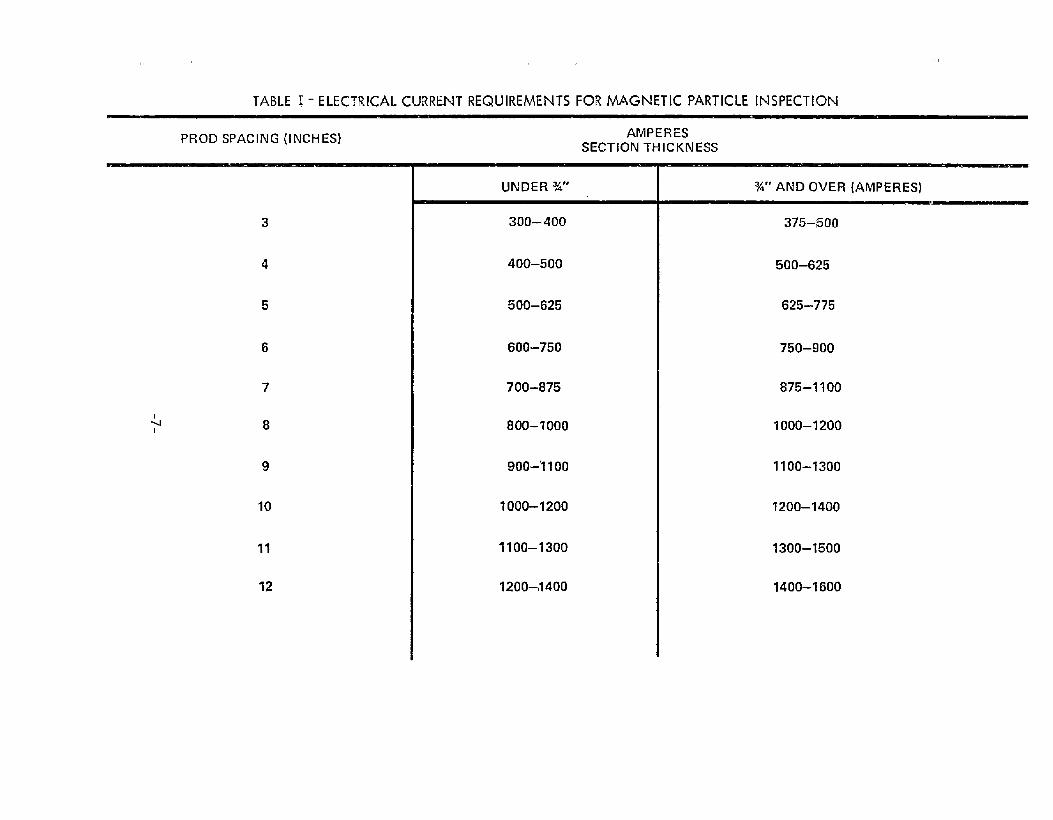
Prod Spacinq. The electrical current required for proper magnetizationmust be selected according to the prod spacing. BeEween 100 and 125amperes of electrical current are required for each inch of prod spacing.
-3-

r‘mom -JJ _
\
7--–’’’”””’’’”-””--—.—.....———-—....”, . .
k=”“- >..-
il “1
y ...L’.%&.,,
3m.
N.OF 58 .. ,.———83131-8..,.* - A -
. . ..
FIG.1 TYPICAL GAUGES FOR INSPECTING FILLET WELDS
-4-

\
\ —.
-5-
w
N

For welds in excess of 3/4” plate thickness, khe current is increasedan additional 257. to 5@A. Table I Iisks the required magnetizationcurrents according to prod spacing and seckion bhickness. It isrecommended thak the equipment include an ammeter to ensure adequat-ecurrenti for proper inspection.
FOK weld inspection, the prod spacing should not be closer than 3“;
and prod spacings in excess of 12” are impractical because of exces-sive current requirements. It is recommended that prod spacingbetween 4“ and 8“ be used.
Prod Positioning. It is very important to maintain good contact toprevent arc strikes and localized heating at khe prod conkack loca–kions. This can be achieved by using pressure with hand inspectionor by utilizing clamping devices. These aspects of magnekic particletesting are especially important- when inspecbinq heat hardenableskeels to avoid creating hard spots or cracks.
A remote control switch should be provided to enable &he operatorturn the current on after the prods have been properly positionedho turn the currenh off before the prods are removed.
‘toand
Surface Preparation Requirements. The as-welded condition is usually
satisfactory for magnetic particle testing without further prepara-tion, except that paint on the base metal must be removed from theprod contact locations - ordinarily by hand grinding or wire brushing.However, test results are affected by contaminants such as dirt,grease, or scale and some surface preparation may be necessary. Aforceful air blast directed on the test area may be useful in remov–ing dirt and scale. When the test area is contaminated with oil orgrease, it should be cleaned with a suikable solvenk. Sand blastingis very effective.
Maqnetic Particle Requirement. The magnetic particles consist of a
finely divided ferromagnetic material which should be of high per-meability and low retentivity. The particles should be selected.
such tihat the size and color provide adequate sensitivity and con-trast for the detection of the discontinuities of interest.
Maqnetic Particle Test Procedure. After the prods have been firmlypositioned and the current has been turned on, the magnetic particlepowder is applied as a light dust. This can be with a dusking bag,an atomizer, or a spray gun. Then with the currenk still flowing. a
gentle stream of air should be directed on the inspection area ko
-6-
,, ,,
TABLE !- ELECTRICAL CURRENT REQUlREhAE14TSFOR MAGNETIC PARTICLE INSPECTION
PROD SPACING (lRICHES)
3
4
5
6
7
8
9
10
11
12
AMPERESSECTION T1-llCKhlESS
UNDER %“
sOO- 400
400–500
500–625
600–750
700–875
800–?000
900-’1100
?000-1200
11 00–1300
1200–,1400
%“ Ah!EI OVER (AMPERES)
375–500
500–625
625–775
750–900
875–1 100
1000–1200
1100–1300
7200–1400
1300- 1!500
1400-1600

remove excess powder and enhance discontinuity indications. Thiscan be done with a low velocity air hose or with a hand operatedsqueeze bulb.
The inspection of long welds requires some overlap be>~ween adjacentweld s~ents.
The Evaluation of Indications. Indications are analyzed and evaluatedon the basis of size, shape, sharpness, and the degree of particleaccumulation. Cracks usually produce strong indications and arereadily identified. Lack of fusion will also produce a strong indi-cation and can be identified by its location at the edge of the weld.
Although discontinuities such as slag, porosity, and lack of fusionlocated slightly beneath the surface may produce indications, theseare fainker and less distinct than those extending to the surface.The type of current being used must be considered in the evaluationof such indications.
lionrdevant Indications. Indications may also be obtained from
undercut or abrupt irregularities on ‘the weld surface. T~ese arenot usually distinct or inkense and can often be correlated withvisual inspection. Under certain conditions, the heat affected zonemay produce an indication. This should not be considered a weldflaw. Similarly, there are combinations of base metal and fillermaterials which differ markedly in magnekic properties. Weld jointsinvolving such combinations produce sharp and intense linear indica–kions at the boundaries of the weld.l This type of indication isunrelated to the soundness of the weld.
Radiography
General. Radiography is a useful tool for the inspection of criticalwelds. It provides a visual presentation, an internal inspectionand a permanent record. A major disadvantage in shipbuilding appli–cation is that this method requires access to both sides of the weld.Also, in r~ard to non–butt welds, interpretation of the radiographbecmnes more difficult as the geomekry deviates from planar to the
1Such a patkern might be obtained when a weld is made involving a
f~rritic (magnetic) and an austenikic (non-magnetic) steel.
-8-

more complex configurations. This aspect of technique is ofparamount importance. While other technique factors such as kilo-volkage (kV), milliamperage (mA), exposure time, distance, ehc. areimportant, a very limited discussion is given here since the informationcan be found elsewhere. 2
Radiation Source Enerqy. The selection of the radiation source fora particular thickness weld is of major importance. If the energyof the source is too high for a given thickness~ then low conhrastand poor radiographic sensitivity results.. Figure 3 is a generalguide for the selection of the maximum acceptable voltage for a giventhickness. It is not necessary to be on the curve. In general,betker radiographic sensitivity is achieved in the acceptable regionof the graph. The upper part of Figure 3 shows the recommended limitsof steel thickness when using iridium or cobalt isotopes.
Factors Affectinq Radiographic Sensitivity. The radiation source tofilm distance, the size of the focal spot, and the dishance of thefront surface of the object to the film are important. in determiningthe sharpness of a radiograph. These parameters are interrelatedand are presented in Figure 4. The minimum diskance from the radia–tion source to the film is given for distances between the sourceside Qf the object and film. For smaller source or focal spot sizes,the source bo film diskance may be reduced. Care must be kaken tobe sure distortion does not interfere with interpre~ation of theradiograph.
selection of Film. There is a wide selection of film available forindustrial radiography. The use of a particular film is primarilyguided by Khe quality level of inspection that is specified andsecondarily by factors such as material thickness or energy of radia–tion source. In general for the initial exposure, use of the fastestrmnfluorescent film types available will be found to produce a 2-2Tqualiky level of inspection.
Where-the geometrical conditions of the weld necessitate a higherlevel of inspection or where scakter conditions may degrade khe
-1
-9-
‘American Welding Society, WELDING INSPECTION, 1968

0.1 0.15 0r2 0.3 0.4 0.6 0.81.0 1.5 2 34567810 15 20
30 I
20
15
65
4
3
2
1 MEV
Cn1--1
0>0-1
z
9008007orl600
500
400
300
200
150
100 -- —0.1 0.150.2 0.3 0.4 0.6 0.87.0. 1.5 2 34567810 15 :
sTEEL SPECIMEN THICKNESS (INCHES)
* BROKEN LINE INDICATES MARGINAL SEtJSITIVITY
)
F]G. 3 MAXIMUM VOLTAGE OR p~DIOAcT~E ENERGY FOR MlN~4uMsTEEL THICKNESS
-1o-

40
~ 30z:ga~
E‘a!-m3
~ 20
I k~
FOCAL SPOT SIZE 5mm
10
0 .5 1,0 1.5 2.0 2.5 INCHES
DISTANCE FROM SOURCE SIDE OF OBJECT TO FILM
FIG. 4 MINIMUM DISTANCE FROM RADIATION SOURCE TO FILM

radiographic quality with the above films, other film are availablethat have a finer grain and can produce a satisfactory qualityradiograph.
Screens. Screens are uniform Ehickness of high atomic numberedmaterial, usually lead, placed in khe cassette so as ho be in inkimatecontact with the film. The screens by kheir intensifying action helpreduce exposure time and also aid in reducing the effect of scatter.Usually lead screens are -O05° thick when used as fronk screens and-010” thick when used as back screens. Their use in radiography ofship welds should be mandatory. The use of lead–film combinationsthat are available commercially is also satisfactory when it displays
the required radiographic quality.
Filters. Filters are materials of high atomic number, usually lead,that are placed between the radiation source and cassekte so as tominimize the effect of scatter. Filters are usually placed immediatelyin front of the cassette. Their use is optional and is usually notrequired when radiographing simple joints but may be of value inradiographing corner or other more complex joinks.
Penetrameters. It is recommended that an image quality indicationthat conforms ho ASTME142-68 be used. This penetrameter consists of
a plaque made Of radiographically similar material to the weldmentand it contains three drilled holes with diameters one, f-we, and fourtimes the plaque thickness. These holes are used in conjunction withthe plaque thickness to establish various image quality levels asgiven in Table II. The 2-2T quality level is generally used for mostinspection. The penetrameter is placed on the source side of the weld.If it is no~ possible to place the penetrameker along side the weld,it may be placed directly on khe weld reinforcement. If khe surfaceripples interfere with the visibility of the hole, the reinforcementmay be smoothed by grinding or other suitable means. Only a minimumamounk of metal should be removed.
Film Density Requirements. A complex joint configuration may causea large film density variation. If the film density falls off alongthe length of the weld, the radiograph should not be interpretedbeyond the area on a film where the density varies more than -15% ofthe density in the center of the film.
-12-
If khe film densitiy varies more than –15% or +3W~ from that on the
penetrameter, two penetrameters may be used to qualify the radiograph.If an acceptable image quality level is shown by the penebrame’kerlocated at the dense part of the radiograph and by the okher placed

il-iH
v) 11-

ak the lower density portion, then the two penetrarneters serve toqualify the portion of the radiograph between the two density values.(Note: Densiky measurements are made along the center line of theweldment) .
Film Reading Requirements. Radiographs should be read in a room withsubdued liqhtinq. The background lighting should be of less intensity
than the a;ea of interest on the radiograph. Care should be takento prevent as little light as possible from being reflected off thesurface of the radiograph.
The intensity and masking of the illuminator is important. The
illuminator should be able to transmit at least 30cd/m2 (0.33 footIamberts) through the area of interest in the radiograph. A mask
over the illuminator should be used to shield very bright areas fromthe film readers’ eyes.
The film readers’ eyes should be exemined ah least once a year forability to see small detail at a normal reading distance of 400mm.The reader should be able to read good print type of 0.5mm height orbetter at this distance.
Ultrasonic Inspection
General. Ultrasonic vibrations can be used to nondestructively
examine the interior of welds. This is done by introducing high-
frequency sound waves into the weld volume with a transducer whichacts reversibly to detect the sonic echoes resulting from reflecting
surfaces within the test object. The echoes are presented on anoscilloscope display and by careful analysis of the oscilloscopepattern, the size and locakion of internal discontinuities can bededuced.
Transducers. Steel welds may be ultrasonically tesked with frequenciesbetween 1 and 5 Mhz. The frequency of 2.25 Mhz is especially well–suited to steel and is recommended. Round transducers are favoredfor straight (longitudinal waves) testing, and rectangular transducersof a ratio 2:1, width to height, are recommended for shear waves. Ineither case, the active element (manufacturers specification) should
not exceed one inch.
Couplants. Ultrasonics will not propagate through an air gap and sometype of liquid is required to couple the transducer and work piece.‘The couplanti should be removed upon comple!zion of inspection.
.14-

Surface Preparation. The surfaces where the probe makes contact withthe weld o+ base metal should be suitable for good acoustical coupling.Plates with loose scale, flaked paint, excess rust, or pittin9 ~i~~require some preparation. Weld splatter can interfere with ultrasonicinspection and must be removed from transducer contact locations.
Ultrasonic Equipment. The ultrasonic instrument used in weld testingemploys an “A-scan” presentation. The circuitry for the instrumentshould include controls for providing continuously increasing signalamplification with respect to time or distance of travel. A cali–
brated decibel attenuator is recommended. Battery-powered equipmentshould contain an alarm to warn of battery depletion prior to instru-ment shut off due to battery exhaustion.
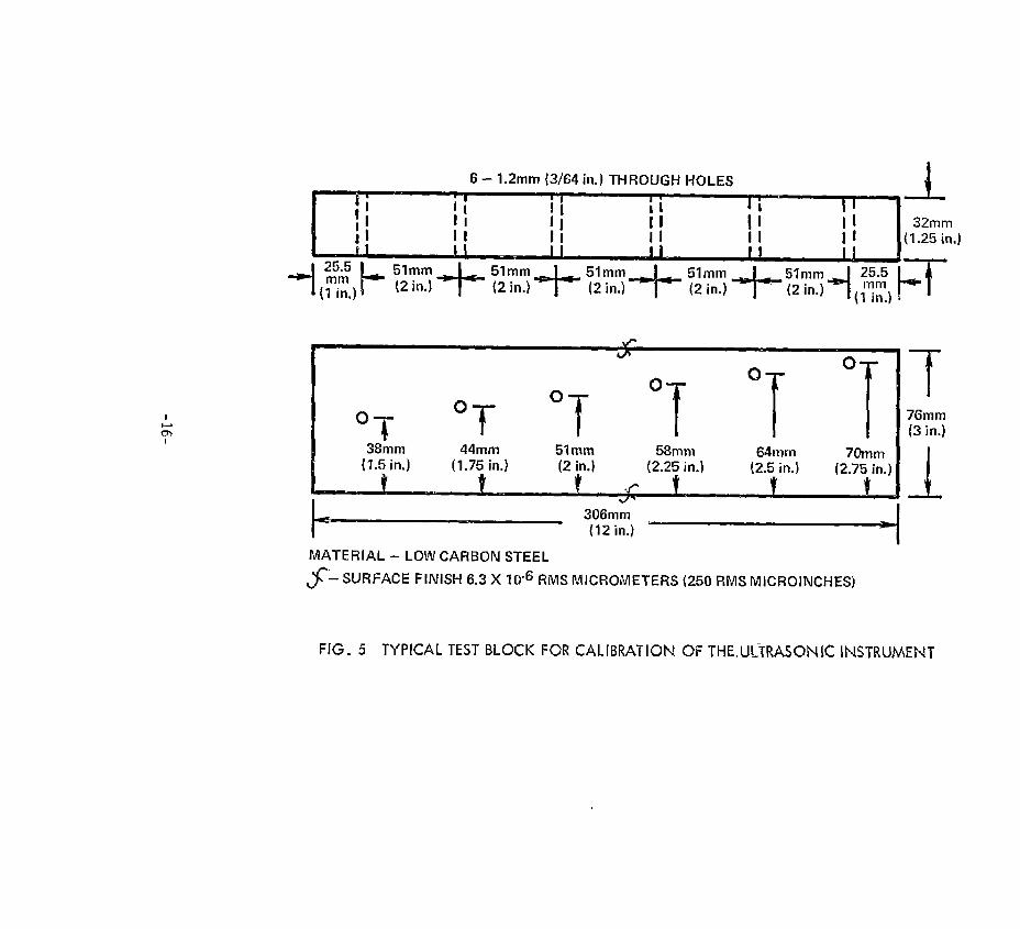
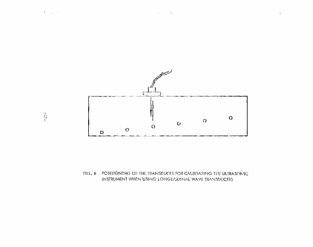
Instrument Calibration. The ultrasonic method i.sessentiallyqualitative, but it can be made quantitative by comparing signalamplitudes with reflectors of known shape, orientation, and area.This can “be done by calibrating the instrument with a suitable testblock. Figure 5 illustrates the basic test block used for instrumentcalibration for ship hull weld inspection using shear waves. Thistest block is also suitable for instrumental calibration when usinglongitudinal waves. Instrument calibration is identical to the pro-cedure for shear waves as set forth in Appendix 1, SSC-213 A GUIDEl?OR ULTRASONIC TESTING AND EVALUATION OF WELD FLAWS (The AmericanBureau of Shipping has also set forth procedures for applying ultra–sonic inspection to hull welds. RULES FOR THE NONDESTRUCTIVEINSPECTION OF HULL WELDS, 1975 (in publication). These differslightly from sSC-213.) The transducer is positioned as shown inFigure 6. Calibration should be performed each time the instrumentis used and recalibration is recommended following any interruptionof electrical power.
Discontinuity Length Determination. The length of a discontinuity isdetermined by maximizing the signal and moving the transducer parallelto the discontinuity and away from the position of maximum signal.The points where the signal amplitude is reduced to one-half aredefined as the extremities. The center line of a shear wave probeand the center of a straight beam probe are used for determining the
extremities of a discontinuity.
Ultrasonic Signal Evaluation. The concepts of ARL (amplitude rejectlevel) and DRL (disregard level) as used in shear wave testing ofbutt welds, Appendix T, are also valid when using longitudinal wavesand for the inspection of non–butt welds. However, ‘&e permissiblelength of
depending
discontinuity for each category may differ for non-butt welds
upon the degree of criticality and should be specified.
-15.
‘-i- ‘T ‘T ‘T ‘T ‘T38hm 44tnm 51mm 58mm{1.5in.)
64mm(1.75 in.) (2 in.}
70mm(2.25 in.) (2.5 in.) (2.75 in.)
MATERIAL - LOW CARBCIN STEEL
$ - SURFACE FINISH 6.3 X lcr6 RMS MICRCJMETERS {250 RMS MICROINCHES)
T76mm{3 in.)
1
FIG. 5 TYPICAL TEST BLOCK FOR CALIBRATION OF T’HE,UtiTRASONiC INSTRUMENT
/_..__!fT
%-—
?-”- _.-=. —-—— — . .
111 ‘cl-“----”c1
0c)
c1c1
_.—. — ..= _ _ . .... . ——__. —
FIG, 6 PQSITlObllNG OF T1-iETRAP45DLKER FCIRcALIBRATING THE LLTRA331NlC
INSTRUMENT WHEN USING LCINGITLJD!NAL WAVE TRANSDUCERS

Dye l?enetrank !l!eskinq
General. Penetrant testing is applicable to weld inspection where
the discontinuities of interest extend to the surface. The methodutilizes a brightly colored dye and a liquid with good propertiesfor capillary action. The surface to be inspected is thoroughlycleaned and then saturated with the liquid. Sufficient time must beallowed for the liquid to penetrate tight cracks or crevices. Afker
removing the excess liquid, some kype of blotkinq material is appliedwhich utilizes capillary action to withdraw the retained penetranh.Surface discontinuities such as cracks are enhanced by the conhrastbetween the brightly colored dye and the blotting material and arereadily detecked by visual inspection.
Dye penetrant testing may be used on welds of any geome~ry orconfiguration providing cerkain fundamental principles are followed:
1. The weld must be clean and free of any material which mightobstruct the penetrant. This includes materials which might have
penetrated into the cracks or discontinuitiies of interest. Cleaning
with a solvent suited to the removal of grease is recommended.
2. Ample time must be allowed for the liquid to penetrate tightcracks or narrow openings. Good practice requires a minimum waiting
time of 15 minutes.
3. Ample time must also be allowed for the blotting material todevelop the flaw indications. Several minutes is usually adequate;however, longer developing times are appropriate for situations where
faint indications are observed.
QUALIFICATION AND CERTIFICATION OF NONDESTRUCTIVE TESTING PERSONNEL
Nondestructive kesting should be performed only by properlyqualified personnel. The American SocieEy for Nondestructive Testing
has published SNT TC-lA Supplements A, B, C, and D which establish
criteria whereby personnel involved in nondestructive testing may becertified as qualified for the radiographic, magnetic particle, ultra-
sonic and penetrant testing methods. Three levels of qualification
are defined:
NDT-Level I – An N3)T Level I individual musk have sufficienttraining and experience to properly perform the necessary tests. Heshall be responsible to a person certified ko NDT Level 11 or NDT
Level IIT for the proper performance of Ehe tests in the applicablemethod.
-18-

NDT-Lewel 11 – An NDT Level 11 individual shall be qualified todirect and carry out tests in the method certified. He must also beable to set up and calibrate equipment (where applicable), read andinterpret indications, and evaluate them with reference to applicablecodes and specifications. He shall be thoroughly familiar with thescope and limitations of the method, and shall have the ability Eo
apply detailed techniques to products or parts within his limit ofqualifications. He shall be able to organize and report nondestructivekesting results.
NDT-Level 111 – An MDT Level III individual shall be capable ofestablishing techniques, interpreting specifications and codes, desig–nating the particular test method and Techniques to be used, andinherpreking the resulks. He shall be capable of evaluating &heresults not only in terms of exisbing codes or specifications, but healso should have sufficient practical background in applicable materialstechnology to assist in establishing tests and acceptance criteriawhen none are otherwise available. It is desirable that he havegeneral familiarity with other commonly used NDT methods. He shallbe responsible for conducting examinations of NDT Level I and NDTLevel 11 personnel.
The inspection methods discussed in this guide should be performedeither by NDT Level II employees or by NDT Level I employees underthe direction of an employee qualified to Levels 11 or 111.
It is the responsibility of the shipyard to designate the level111 employee. It- is then his responsibility to ascertain proper
education and training for employees certified as qualified forLevels I and 11 work. It is also the shipyards responsibility todetermine that nondestructive testing performed on a contractualbasis is done by properly qualified personnel.
RECOMMENDED INSPECTION PROCEDURES FOR SPECIFIC JOINT CONFIGURATIONS
The American Welding Society recognizes four basic types of weldjoint other than the butt – the corner, ‘Tee, “x”, and the lap. A1lother joints are varieties of these basic types. The techni~es andprocedures for these joints, as discussed in this guide, uses thesimple case of right angle geometry. It is recognized that deviationsfrom right angle geometry might be encountered in practice. Althoughthe basic principles should be applicable, caution is recommended
especially with ultrasonic inspection.
-19-

The selection of a nondestructive test method should be basedupon the need to detect cerbain types of weld defects which areacceptable either because of service requirements or company stand–
ards. This guide lists khe methods which are most suitable for
detecting specific weld discontinuities and describes the proceduresfor applying each method to the various joint configurations.
Corner Joints
Corner joints may be welded either with complete penetration orintentional partial penetration. Joints welded with complete
penetration may be prepared two ways as shown, The typical welddiscontinuities for each of these categories and the nondestructivetests suited for the dekection of each type flaw are presented below:
Joint Preparation
rPartiall?enetrakion
rFullPenetration
F-FullPenetration
Defect
Unacceptableweld profileCracks
Unacceptableweld profileCracks
incomplete pene–lxation
Lack of fusionslagPorosity
Unacceptableweld profileCracks
Incomplete pene-trationLack of fusionSlag
Methods for Inspection
Visual, weld gauge
Visual, magneticparticle
Visual, weld gauge
Visual, magneticparticle
Radiography
RadiographyRadiographyRadiography
Visual, weld gauge
Visual, magneticparticleUltrasonics
UltrasonicsIladiography
Porosity RadiographyLaminations Ultrasonics
Visual inspection and the magnetic particle method are the primarynondestructive testing procedures used on corner joints designed forpartial penetration welding.
720-

Visual Inspection. Visual inspection provides:
1. A measurement of fillet size, Figure 7A.
2. The determination that fillet concavity and convexity arewithin specified limits, Figure 7B and Figure 8A.
3. Excessive reinforcement can be measured, Figure 8B.
4. Undercut can be measured with a depth gauge.
5. Visual inspection may also disclose cracks in the weld or
adjacent material. Cracks are not usually permitted in weld jointsand their detection should be called to the attention of qualityassurance personnel for disposition.
Nlaqnetic Particle inspection. The magnetizing currents for different
thickness of steel and for various prod spacings are given in Table I.When differenk thicknesses of base metal are involved, the average ofEhe two thicknesses should be used in determining currenb requiremen~s.
Magnetic particle inspection of the exterior of a corner joint isaccomplished first by positioning the prods upon the weld and thenby positioning the prods on opposite sides of the weld, Figure 9.
The interior of the joint should also be inspecbed. First, byplacing tihe prods upon the weld and then by positioning the prods onapproximately opposite sides of the weld.
The geometry of the interior of a corner restricts the positioningof prods on strictly opposite sides of the weld wikhin tihe limitssuggested for prod spacing. This difficulty can be resolved by off-setting the prods so that the path between them is at a slight angleto Ehe weld. The deviation from strict perpendicularity to the weldwill result in a slight decrease in sensitivity for detecking trans-verse discontinuities but the inspection will still be adequate.
Yokes are not recommended for use on corner welds because of geometricalrestrictions and the difficulty of making good contact.
-21-
All cracklike indications should be considered significant. Dependingupon the type of current used, some indications may be obtainedrelabed to the partial penetration. This should not be regarded asa weld defect.

TO DETERMINE THE SIZE OFA CONVEX FILLET WELD
TO DETERMINE THE SIZE OFA CONCAVE FILLET WELD
PLACE GAUGE AGAINST THE TOE OF THESHORTEST LEG OF THE FILLET AND SLIDEPOINTER OUT UNTIL IT TOUCHES STRUCTUREAS SHOWN. READ “SIZE OF CONVEX FILLET”ON FACE OF GAUGE.
A
PLACE GAUGE AGAINST STRUCTURE ANDSLIDE POINTER (3UT UNTIL IT TOUCHESTHE FACE OF THE FILLET WELD AS SHOWN.READ “SIZE OF CONCAVE FILLET” ONFACE OF GAUGE.
B
FIG, 7 PROCEDURE FOR MEASUR!NG THE S[ZE OF CONCAVE AND CONVEX FILLET WELDS

TO CHECK THE PERMISSIBLE TOLERANCE OF CC)NVEXiTY
AFTER THE SiZE OF A CONVEX WELD HAS BEEN DETERMINED,PLACE THE GAUGE AGAiNST THE STRUCTURE AND SL[DEPOINTER UNTi L IT TOUCHES FACE OF FILLET WELD AS SHOWN.
FIG . 8A PROCEDUREFOR MEASURING THE PERMISSIBLETOLERANCEOF CONVEXITY ON FILLET WELDS
GAUGE
FIG. 8B PROCEDURE FOR MEASURING WELD REINFORCEMENT
-23-

m
r-
-25-

-26-

\
Tm
-27-

F
FIG 12A FULL PENETRATION CCRI-4ER JOINTS DONE WITHOUT CHAMFERS
NUMERALS
G. 12B TECHNIQUE FOR THE RADIOGRAPHICFULL PENETRATION CORNER JOINTS
-287
lNSPECTIQN OF

Joj.nt PreparatiQ1l.
T PartialPenetration
Defect
Unacceptableweld profile
cracks
Unacceptableweld profile
CracksI *I {
Incomplete pene-
11 Fu~~ ErakionPenetration Lack of fusion
SlagPorosityLaminations
Methods for inspection
Visual, weld gauge
Visual, magneticparticle
Visual, weld gauge
Visual, magneticparkicleultrasonics, radiography
ultrasonics, radiographyRadiography. ul~rasonicsRadiographyultrasonics
Visual and I’4aqneticParticle Inspection. The visual inspection of
T–joint welds is identical to the procedures described for cornerjoints. The magnetic particle inspection of a T–joint is identical
in procedure to that for the inkerior of a corner joint. The require–
ments for magnetizing current are presented in Table 1. For cases
where the web and flange may differ in thickness, an average thicknessis to be used in determining the applicable current requirements fromTable 1. T–joint welds which require critical inspec~ion are usually
tested using ultrasonics. Radiography may be useful as a supplemental
technique, particularly for evaluating discontinuikies dertected withultrasonic inspection.
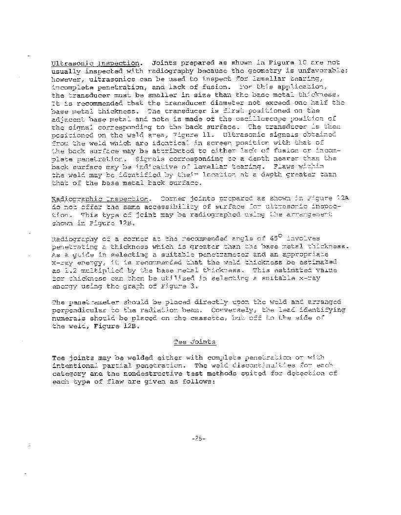
ultrasonic inspection. ultrasonics may be used to inspect both full
penetration and partial penetration welds for Iamellar tearing andunderbead cracking. For this type inspection, khe ‘transducer (straight
beam) is placed on the flange, Figure 13A, and the screen position
of the signal obtained from the back surface is marked. Signals
obtained from the weld zone at lesser depths may indicate Iameilartearing or underbead cracking. Full penetration welds can also be
inspected for incomplete penetration and lack of fusion. These dis–
continuities produce signals at the same depth as the back surfaceof the flange. Discontinuikies wikhin the weld will produce signals
which correspond to depths deeper than the back surface of tihe flange.
An angle beam transducer (45° is recommended) can be positioned asshown in Figure 13B to inspect for toe cracks or underbead cracking
-29-
TRANSDUCER POSITION TRANSDUCER POSITION
FIG. 13A ULTRASONIC PROCEDURE FOR THE INSPECTION OF T-JOINTWELDS WITH LONGITUDINAL WAVES
CRACK
FIG. 13B ULTRASONIC TEST
SHEAR WAVE lF4SPECT10N
PROCEDURE FOR
-30-

at the edge of Ehe weld. Before the angle beam search is done, a
straight beam transducer is used to locate the edge of the weld.Simple geometrical considerations can then be used to determine theproper position for the angle beam transducer. For complete inspection,
the weld should be searched from both sides.
The inspection for toe cracks may also be performed on the web, however,a web thickness of at least 1/2” is desirable.
Radiographic Inspection. T-joint welds may be radiographer using the
arrangement illustrated in Figure 14. FU1l inspection requires that
each fillet- be radioqraphed separately.
The radiography of a T-joint is complicated by Ehe non-uniform thick-ness presented to the x-ray beam. In selecting a penetrameter, it isrecommended that the thickness at mid-point of bhe weld be used. This
thickness (for 45° angle) is determined by multiplying the flangethickness by 1.4 and adding to this the measured thickness of the weldthroat, Figure 14A.
The penetrameter, lead identification numerals, and cassette, should
be positioned as shown in Figure 14A.
Because of the differences in Ehickness to be penetrated by the x–raybeam, differences in film density are to be expected. Interpretation
should be restricted to those areas of the weld which have a filmdensity of at least 2.0. Compleke inspection may require more thanone exposure. These difficulties may be somewhak alleviated by select–ing an x-ray inspection energy close to the upper limit in the graphof Figure 3.
“X’’-Joint
X–joints are ordinarily prepared for full penetration welding. Typi ca1flaws and the inspection methods suited for detecting these flaws arepresented below:
Joint Preparation Defect Method for Inspection
+ FullPenetration
Unacceptable Visual, weld gauge
weld profileCracks Visual, magnetic
particle, ultrasonicsIncomplete pene- Ultrasonics, radiographytrationLack of fusion Ultrasonics
Slag Ultrasonics, radiography
Porosity Radiography
-31-

45“
h-
illzLuQ
7A = WELD TtiROATi!! = 1.4 X FLANGE THICKNESSc =A -t B = WELD THROAT PLUS 1.4
MULTIPLIED BY THE FLANGE THICKNESS
I
L
-32-

Visual and Maqnetic Particle Inspection. Each of the four fillets ofan X-joint constitutes a corner joint and visual and magnetic particleinspection techniques for these fillets are the same as those for cor–ner joints. Critical inspection for subsurface flaws may be accom–plished using radiography or ultrasonics.
Radiographic Inspection. Figure 14B illustrates the arrangaenk forradiography. Better quality radiographs are obtained by minimizing
the object to film distance; and considering the restriction on acces–sibiliky, the film and cassetke should be no wider khan necessary butadequate to include the enkire weld and adjacent heat affected zoneson the radiograph. Radiography should be performed from mutually per–
pendicular directions. Directing the radiation beam ak an anglebisecting the corner (45°] will produce a radiograph with the most
uniform film densiky.
For radiography at an angle of 45°, the thickness to be penekraked is
calculated by adding the angular path of the radiation through khebase metal (1.4 multiplied by &he base metal thickness) and t-he Ewo
weld throats, Figure 14B. The penetrameter should be placed direcklyon the weld and perpendicular to the x–ray beam. The identifying leadnumerals should be placed on the cassetke at the extreme end.
The calculated thickness &o be penetrated can be utilized in conjunc-tion with the graph of Figure 3 to select a suitable x–ray energy.
Radiography may be expected to reveal incomplete penetration, slaginclusions, and porosity. Favorably oriented cracks and lack offusion may also be detected.
Ultrasonic Inspection. Ultrasonic inspection is restricted to angle
beam techniques. Shallow angles (70°) are recommended. The trans–ducer is placed on the base metal and directed perpendicular to theweld, Figure 15. Calibration for distance or depth is necessary.Because the geometry is complex, caution must be exercised in evaluat-ing all ultrasonic signals. In khis regard, a test block of identicalgeometry and dimensions is useful. Further, artificial discontinui-ties may be introduced into the test weld ko aid in evaluating ultrasonicsignals obtained from production welds and to provide assurance offlaw detection capabilities. Complete ultrasonic inspection requiresexamination of the weld from all eight faces.
Lap Joint
Lap joints are usually fabricated as shown.
suited for specific types of flaw detection
-33-
The nondestructive testsare presented as follo-ws:

id-P
FIG. 15 ULTRASONIC PROCEDUREFOR INSPECTING AN “X” JOINT WELD
Jointi Preparation Defect Method of Inspection
Unacceptable Visual, weld gaugeweld profile
Cracks Magnetic particle,
/h
Ir~diograplzy
Slag RadiographyPorosity RadiographyLack of fusion Radiography
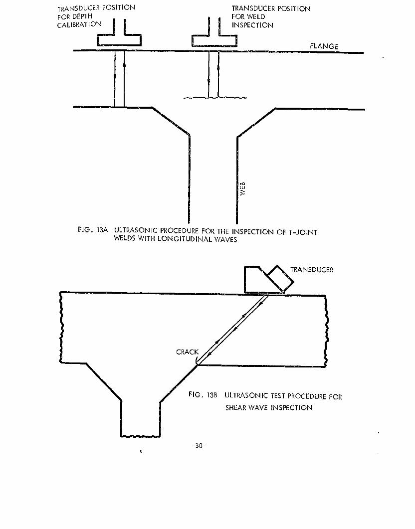
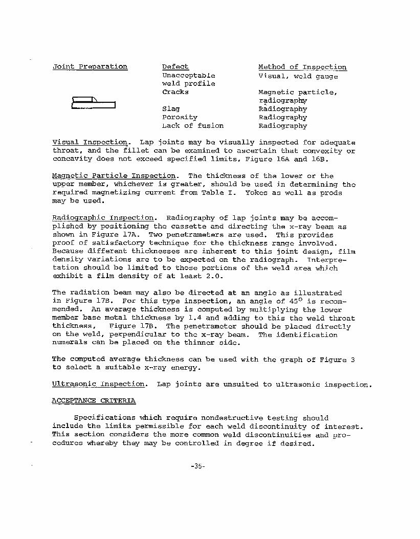
Visual Inspection. Lap joints may be visually inspected for adequate
throat, and the fillet can be examined to ascertain that convexity orconcavity does not exceed specified limits, Figure 16A and 16B.
Maqnetic Particle Inspection. The thickness of the lower or theupper member, whichever is greater, should be used in determining kherequired magnetizing current from Table I. Yokes as well as prodsmay be used.
Radiograph.ic Inspection. Radiography of lap joints may be accom–plished by positioning the cassette and directing the x–ray beam as
shown in Figure 17A. ‘Two penetrameters are used. This providesproof of satisfactory technique for the thickness range involved.Because different thicknesses are inherent to this jointi design, filmdensity variations are to be expected on the radiograph. lhterpre-kation should be limited to those portions of the weld area whichexhibit a film density of at least 2.o.
The radiation beam may also be directed at an angle as illustratedin Figure 17B. For this type inspection, an angle of 45° is recom-mended. An average thickness is computed by multiplying the lowermember base metal thickness by 1.4 and adding to this the weld throatthickness, Figure 17B. The penekrameter should be placed direcblyon the weld, perpendicular to the x–ray beam. The identificationnumerals can be placed on the thinner side.
The computed average thickness can be used with the graph of Figure 3to select a suitable x-ray energy.
Ultrasonic Inspection. Lap joints are unsuited to ultrasonic inspection.
ACCEPTANCE CRITERIA
Specifications which require nondestructive testing shouldinclude the limits permissible for each weld discontinuity of interest.This section considers the more common weld discontinuities and pro–
cedures whereby they may be controlled in d~ree if desired.
-35-
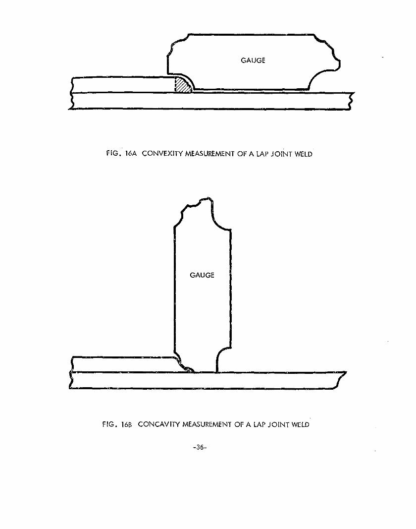
FIG. 16A CONVEXITY MEASUREMENT OF ALAPJOINTVVELD
GAUGE
FIG. 16B Concavity MEASUREMENT OF ALAPJOINTWELCI
-36-

x IPENETRAMETER
PENETRAMETER LEAD NUMERALS
1 1CASSETTE
FIG. 17A ARRANGEMENT FORA IAP JOINT WELD
A = WELD THROAT THICKNESS
B = 1.4 X THICKNESS OF LOWER MEMBER
PERFORMING RADIOGRAPHY
PENETRAMETER . /
450
OF
CASSETTE
FIG, 175 ALTERNATE
\
ARRANGEMENT FOR P~RFORhAING ~D!OGMPHY OF-4AMP JOINT WELCI
-37-
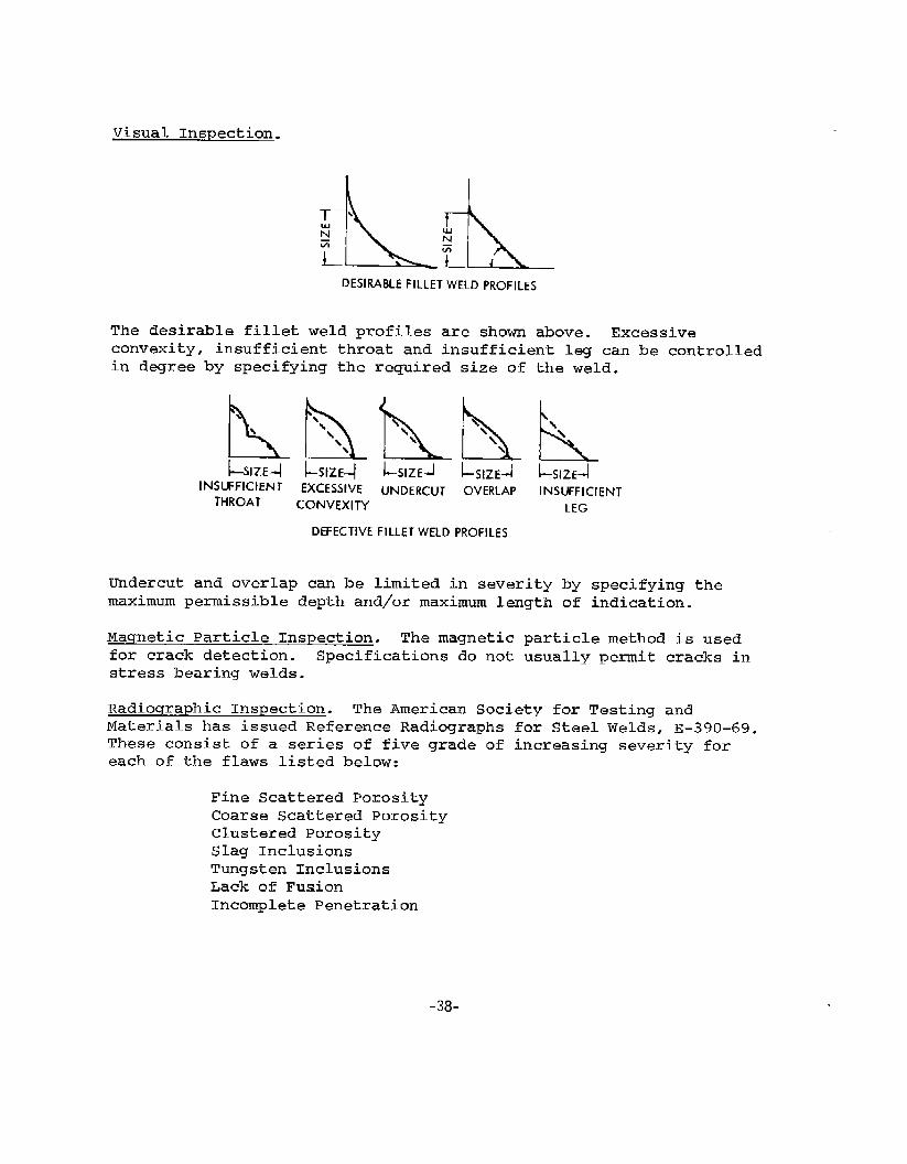
Visual Inspection.
DESIRABLE FILLET WELD PROFILES
The desirable fillet weld profiles are shown above. Excessiveconvexity, insufficient throat and insufficient l= can be controlledin degree by specifying the required size of the weld.
INSUFFICIENT EXCESSIVE lJNDERcIJT OVERLAP INSUFFICIENTTHROAT CONVEXITY
DEFECTIVE FILLET WELD PROFILES
LEG
Undercut and overlap can be limited in severitymaximum permissible depth and/or maximum length
by specifying theof indication.
Maqnetic Particle Inspection. The magnetic particle method is used
for crack detection. Specifications do nob usually permit cracks in
stress bearing welds.
Radiographic Inspection. The American Society for Testing and
Materials has issued Reference Radiographs for Steel Welds, E–390–69.These consist of a series of five grade of increasing severity foreach of the flaws listed below:
Fine Scattered PorosityCoarse Scattered PorosityClustered PorositySlag InclusionsTungsten InclusionsLack of FusionIncomplete Penetration
.3a_

Single illustrations are given of other types of weld discontinuitieswhich may be detected by radiography but are not usually controlled indegree.
The reference radi~raphs are available for thickness of 0.030”, 0.080”,0.187”, 0.375”. 0.750”, 2.0”, and 5.0”. These reference radiographs
are not in themselves specifications but may be used to control weldquality. This would be done by selecting illustrations of maximum per–
missible severity for each flaw type of interest, which would form apart of the contractual agreement.
ultrasonic Inspection. The procedure for inskm.unent calibration, set
forth in Appendix I, provides a technique for weld inspec~ion wherethe oscilloscope indications may be separated into three general cate–gories. This is done by defining an amplitude disr~ard (DR) level at
4@A of full screen height and an amplitude reject (AR) level at SO?%of full screen height.
With the instrument properly calibrated, the planar type flaws such ascracks or lack of fusion typically produce a high-amplitude signal inexcess of the “AR” level. Indications less than the “DR” level are notusually attributed to serious flaws are disregarded. Signals betweenthe “AR” and “DR” levels are usually related to non-planar weld discon-
tinuities such as slag.
In addition to the requirement for proper instrument calibration,specifications involving ultrasonic inspection should consider themaximum length for flaws above the “AR” level and for those greater
than the “DR” but less than the “AR” level. Weld quality may also bycontrolled by specifying the permissible cumulative flaw length or bylimiting the distance between flaws.
Typical weld flaws and their signal amplitudes in relation to the ARand DR levels are presented in the schematic of Figure 18.
-39-

100
CRACKS CRACK LIKE SLAG“ INCOMPLETE PENETRATION — PIPING 90LACK OF FUSION LINEAR POROSITY
— 80
- SEVERE POROSITYMLJLTIPLE SLAG INCLUSIONS
70
ROUND E13GE SLAG- CLUSTERED POROSITY
b 60
50
40
iVllLD SCATTERED POROSITY30
20
10
0
- ARL
- DRL
F!G. 18 TYPICAL ULTRASONIC SIGNAL AMPLITUDES PRODUCED BY VARIOUS DEFECTS
APPENDIX A
SSC–213
A GUIDE FOR ULTRASONIC TESTING AND EVALUATIONOF WElX3 FLAWS
This document presents procedures and acceptance limitsfor contact ultrasonic inspection of steel butt welds in thethickness range of 1/4 to 2 inches. The acceptance limitsdescribed in the following sections are compatible withthose set forth in SSC-177, “Guide for Interpretation ofNondestructive Tests of Welds in Ship 13ull Structures” forradiographic inspection and should therefore result in satis-factory ship welds. Occasions may arise where radiographicinspection could provide additional information.
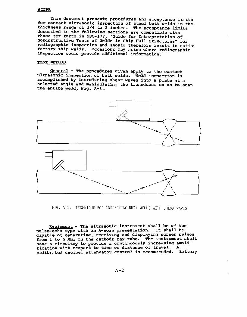
General - The procedures given apply to the contactultrasonic inspection of butt welds. Weld inspection isaccomplished by introducing shear waves into a plate at aselected angle and manipulating the transducer so as to scanthe entire weld, Fig. A-1.
Izf!L-J\./-’
FIG.A-1. TECHNIQUE FOR INSPEC”[lNGBUT-(WELDSWII”HSHEARliAVES
A-2
EcruiDment- The ultrasonic instrument shall be of thepulse-echo type with an A-scan presentation. It shall becapable of generating, receiving and displaying screen pulsesfrom 1 to 5 MHz on the cathode ray tube. The instrument shallhave a circuitry to provide a continuously increasing ampli-fication with respect to time or distance of travel. Acalibrated decibel attenuator control is recommended. Battery

powered equipment must contain an alarm to signal batterydepletion prior to instrument shut-off due to battery exhaustion.
Transducers - The maximum dimension (manufacturers’specifications) of the transducer active element shall notexceed one inch. A ratio of 2:1 width to height of the activeelement is recommended. A nominal test frequency of 2.25 YE&is recommended.
Selectiqn of Probes - The primary consideration forselecting a probe shall be the thickness of the plate. Thefollowing shear wave angles are recommend~:
70° for plate thicknesses 1/4” to 1/2”
60° or 70° for plate thicknesses 112” to 1-1/2”
45° or 60° for plate thicknesses 1-1/2” to 2-1/2”.
The transducer angle should be checked periodically with theInternational Institute of Welding Test Block, Fig. A-2.
Couplant - A liquid such as glycerin diluted with alcoholor water and to which a wetting agent has been added isrecommended for acoustic coupling between the transducer andthe plate. Most oils are acceptable. For overhead work antifor places of difficult access certain types of grease may
1- ——.-–200—7p I
r ‘1 , ~~ ‘ ~
,5 ~__++.,5 ,/’:0” J.
60°
i /’55
1:
,x 91I00
@.–g ,/
50 (jd
100,,.”-.”+‘,,.
30 ,‘,’,.,,,,’
;/’’”” 1
I.–35+!PLASTIC DISC
NOTE: ALL DIMENSIONS IN MILLIMETERS1 INCH 25.4MM
FIG.,4-2. IIITERNATIONALINSTITUTEOF I;KLDINGTEST BLOCKFOR ULTRASONICCALI13RATIOh
A-3

prove useful. Any couplant should be removed upon completionof the inspection.
Surface Preparation - The average plate as received fromthe mill has a surface that is smooth enough for ultrasonicinspection. Plate with loose scale, flaked paint, excess rust,or pitting will require grinding. After welding, the surfaceof the base metal where the probe is to be manipulated shouldbe cleaned of weld splatter. If surface irregularities on theweld bead interfere with the ultrasonic test or cause diffi-culties in interpretation then the weld bead should be groundreasonably smooth.
Base Metal Inspection - Although the presence of laminationsin the base metal may not be a basis for rejection, thesereflectors may mask a part of the weld from the ultrasonicbeam, Fig. A-3, or cause the operator to incorrectly locatea discontinuity, Fig. A-4. Laminations can be detectedultrasonically with a straight beam {longitudinal waves) .When laminations are encountered, the inspection should bemade from the other side of the weld.
PERSONNEL QUALIFICATION
Supplement C, Ultrasonic Testing Method, TC-lA RecommendedPractice, American Society for Nondestructive Testing, shall apply.Ultrasonic testing may be carried out by a Level 11 operator orby a Level I operator under the direct supervision of a Level 11operator.
FIG.A-3. MASKINGEFFECTOF A BASEMETALLAMINATION
FIG.A-4. POSITIONERRORSINTRODUCEDBY BASE.METALLAMINATION
A-4
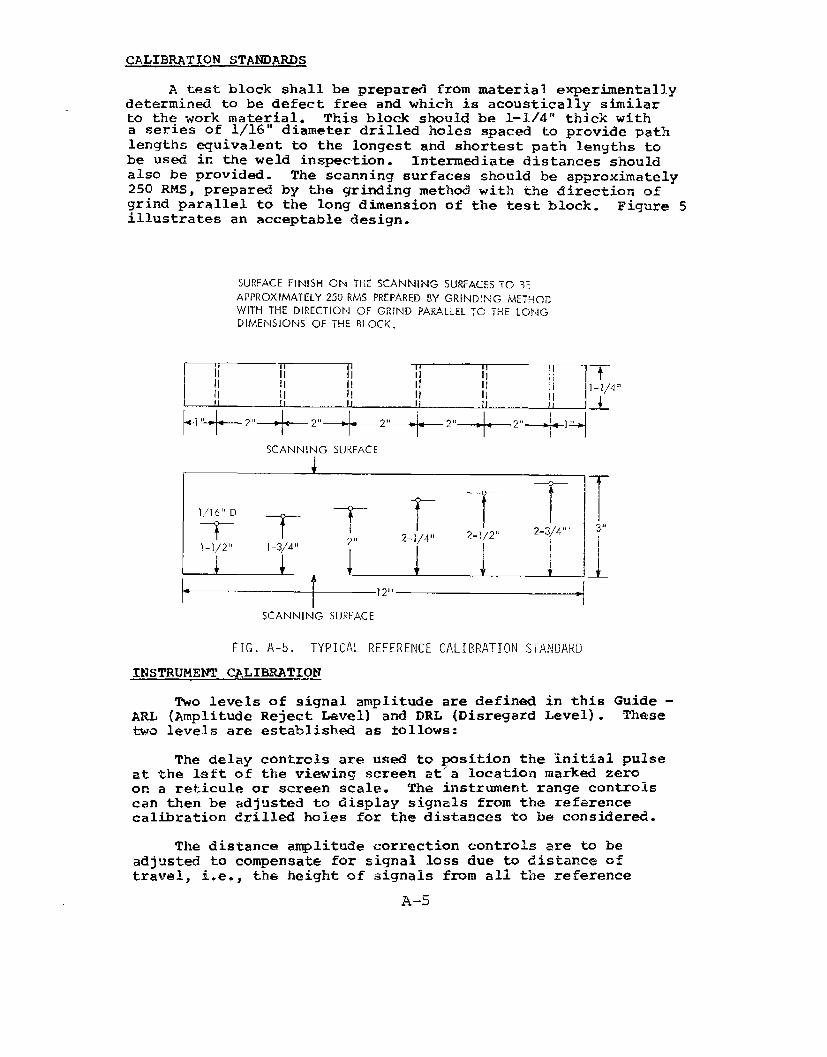
CALIBRATION STANDARDS
A test block shall be prepard from material experimentallydetermined to be defect free and which is acoustically similarto the work material. This block should be 1-1./4”thick witha series of 1/16” diameter drilled holes spaced to provide pathlengths ~uivalent to the longest and shortest path lengths tobe used in the weld inspection. Intermediate distances shouldalso be provided. The scanning surfaces should be approximately250 RMS, prepar~ by the qrindinq method with the direction ofgrind parallel to tfielong dimen;ionillustrates an acceptable design.
SURFACE FINISH OH THE 5CANNIP.JGAPPROXIMATELY25CIRMS PREPAREi3BY
of the test block. Figure 5
5WWACZ5i0 3E
GR[ND!NG /METHODWITH THE DIRECTION OF GRIND PARALLELTO THE LONGDIMENSIONS OF THE BLOCK.
FIG.A-5. TYPICALREFERENCECALIBRATIONSTANDARD
TNSTRIJMENT CALIBRATION
TWO levels of signal amplitude are defined in this Guide -ARL (Amplitude Reject Level) and DRL (Disregard Level). Thesetwo levels are established as follows:
The delay controls are used to ~sition the initial pulseat the left of the viewing screen at”a location marked zeroon a reticule or screen scale. The instrument range controlscan then be adjusted to display signals from the referencecalibration drilled hales for the distances to be considered.
The distance amplitude correction controls are to beadjusted to compensate for signal loss due to distance oftravel, i.e., the height of signals from al?. the reference
A-5

drilled holes should be made equal.
When a decibel attenuator is available, the instr-entgain control is to be adjusted to set the qualiz- signalsfrom the reference reflectors at 40% of full screen height,Fig. A-6. The gain is then increased by 6 decibels. At thiSsetting, the MU is 6 decibels above the 40% line and the DRL(screen height below which indications are to be disregarded)shall be the 40% line, Fig. A-6.
when a decibel attenualmr is not available, the instrumentgain @ntrol is to be adjustd to set the equaliz~ signalsfrom the reference reflectors at 80% of full screen height,Fig. A-7. For this setting the 40% line shall be the DRL andthe 80% line shall be fche ARL, Fig. A-7.
In both of the above cases the calibration should bechecked fr~uently.
WELD INSPECTION
Longitudinal defects are found by directing the sound beamnormal to the length of the weld and -ving the transd”mer backand forth, Fig. A-8, to scan the entire weld. Simultimeous ly,the transducer is oscillated through a small angle. The backand forth motions should be repeated at intervak which do notexceed 80% of the width of the transducer as the probe As movedalong the weld.
Transverse defects are detected as follows:
For welds ground smooth the transducer isplac~”on top of &he weld and moved along its lengkh,Fig. A-9.
b. For welds not ground smooth the transduceris placed alongside and not quite parallel to theweld and nmved along the length, Fig. A-lo.
The entire weld ati heat affect~ zone should be scannd.The weld should be inspect- from both sides of one surface,
~ISCONTINtJITY LENGTH DETERMInTIO?K
When discontinuities are de,tectd, the sound beam slmuldbe directed so as to maximize the signal amplitude. Thetransducer is then moved parallel to the discontinuity andaway from the psition of maximum signal amplitude. Theextremity of the discontinuity is defined as the point atwhich the signal amplitude drops to on~half of the peakvalue. This point is marked using the center line of the wedgeas an index. In a similar manner, the other extremity is foundand the distance between marks is defined as the length of thediscontinuity. The minimum recordable length of a discontinuityshall k 1/8”.
A-6

. .—..—— .- 100
— --—- —- 90
ROXIMATELY 80Y0-— — — — — —, .,. ~o”
3:
.-
——. 70—.— .—
— .-— _.., —— . . 6 db___ 60
IL——.— “—-.— 50
40
-. 30
4 20
—- 10
L\-l \ “’ ; I I <I I I o1
,
FIG.A-6. TYPICAL VIEWING SCREEN CALIBRATIONFOR lNSTP.LM4ENTSWITH DECIBELATTENUATIONCONTROLS
ARL
DRL
ARL
DRL
FIG. A-7. TYPICAL VIEWING SCREEN CALIBRATIONFOR “INSTRUMENTS WITHOUT DECIBEL ATTENIJATION CONTROLS
NOTE: CALIBRATION IS PERFORMED WITH THE REFLECTION OBTAINED FROM THE WALL OF A1/16” DRILLED HOLE USINGD15TANCE-A~lPLITUDECORRECTIONS.
A-7
-. —.---..—

TRANSDUCER SONIC
(a)
NOTE: USE SIMILAR SCAN PATH ON OPPOSITE SIDE OF WELO IMSAM:. SURFACE.I I
% )
FIG. A-8. TECHNIQUE FOR INSPECTINGBUTTWELDSWITH SHEARWAVES
TRANSDLICER /“ /’
4
/~/ //
/
N 30”ANGLE OF
/ ROTATION/ /’
//
FIG.A-9. SUPPLEMENTARYTECHNIQUEFORINSPECTING BUTT WELDS WHENTHE WELD BEAD
IS GROUNDFLUSH
FIG.A-10. SUPPLEMENTARY TECHNIQUE FORINSPECTINGBUTTWELDSWHEN THE WELD BEAD IS
NOT GROUND FLUSH
A-8

DISCONTINUITY EVALUATION
Discontinuities which do not produce signal amplitudesequal to or greater than the DRL, Fig. A-11, shall bedisregarded.
Discontinuities which cause signal amplitudes equal toor greater than the DRL but less than the ARL, Fig. A-12,require a length determination and are evaluated as follows:
a. Defects with length greater than ~ T where ‘1’isthe thickness of the plate are unacceptable.
b. For multiple indications, where L is the lengthof the larger discontinuity, if the separationdistance is less than 6L then the sum of theadjacent lengths shall not exceed ~ T. If theseparation distance is more than 6L then thecumulative length in any 6“ length of weld shallnot exceed the plate thickness.
my discontinuity which produces signal amplitudes in excessof the ARL, Fig. A-13, is unacceptable.
When base metals of different thicknesses are weldedtogether the thickness of the thinner member shall be used indeterminations of acceptable limits of discontinuities.
With the ultrasonic instrument calibrated in accordancewith the procedures set forth in this Guide, usual signalamplitudes for specific type weld defects in relation to theARL and DRL are illustrated in Fig. A-14.
When rejectable conditions are encountered, radiographymay be useful in determining the nature and extent of thediscontinuity.
RECORD OF ‘INSPECTION
The record of each weld inspection should include:
::3.4.
::
::9.
10.11.12.13.
Operator’s identityDateInstrument identityTransducer type, size, frequency and angleIdentification of test objectLocation of the weldType of materialThickness of base plateType of joint and configurationCondition of the weld beadCouplantFlaw dataInspection coverage, including reference points.
A-9

. .—
INDICATIONS BELOW THE DRLLEVEL ARE TO BE DISREGARDED
50
DRL— ~~ 30
20
\,10
1 1 I 2 1 1I
11 1 0
FIG.A-Il. TYPICAL EXAMPLE OF ULTRASONIC INDICATIONS BELOW THE DRL.
v 101 I 1 I 81 1 1
LI 1 1 o)
INDICATIONS EQIJAL TO OR GREATERTHAN THE DRL LEVEL BUT LESS THANTHE ARL LEVEL REQUIRE A DETERMI-NATION OF DEFECT LENGTH ANDSEPARATION DISTANCE
.
FIG. A-12. TYPICAL EXAMPLE OF ULTRASONIC INDICATIONS BELOW THE DRLBUT LESS THAN THE ARL
I I
1
II1 I ~~ ‘y: 1
100
90
ARL— 80
70
60
50
DRL 40!
30
20
10
0
WELDS WHICH PRODUCE INDICATIONSEQUAL TO OR GREATER THAN THEARL LEVEL ARE REJECTABLE
FIG. A-13. TYPICAL EXAMPLE OF ULTRASONIC INDICATIONS ABOVE THE ARL
A-10

WITH THE ULTRASONIC INSTRUMENT CALIBRATED IN ACCORDANCE WITH
THE PROCEDURES SET FORTH IN THIS GUIDE, WELD DEFECTS OF THETYPES LISTED W!LL USUALLY PRODUCE SIGNAL AMPLITUDES IN RELAT’ION
TO THE ARL AND DRL LEVELS AS SI+OWN:
/
100CRACKS CRACK LIKE SL4G
- INCOMPLETE PENETRATION PIPING 90
LACK ‘OF FuSION LINEAR POROSITY80–
SEVERE POROSITY
–MULTIPLE SLAG INCLUSIONS 70
ROUND EDGE SLAG– CLUSTERED POROSITY 60
50
MILD SCATTERED POROSITY
30
1 I o
ARL
DRL
FIG. A-14. TYP”ICALULTRASONIC SIGNAL AMPLITUDES PRODUCED BY VARIOUS DEFECTS
A-n

G~SSARY OF TERMS
A-Scan - A method of data presentation on a cathode raytube utilizing a horizontal base line whichindicates elapsed time when reading from leftto right. A vertical deflection from the baseline indicates reflected signal amplitudes.
Acoustically l?he same type of material as that to beSimilar - inspected, or another material which has been
experimentally proven to have acoustic velocitywithin +3% and an attenuation for shear waves atthe frequency to be used within +0.25 dB/inch ofthe material to be inspected.
ActiveElement - The piezo-electrical material in the ultrasonic
probe.
ARL (AmplitudeFtel~ct Level - The horizontal level on the cathode ray tube
established by calibration. After calibrationthe ARL is 80% full screen height or 6 dB abovethe 40% line if a decibel attenuator is available.
Decibel - A logarithmic function of the ratio of twovalues. In ultrasonics the two values are thesignal amplitude and a reference amplitude.
Decibel~ttenuatir - A gain control calibrated in decibels.
DelayControls - An electronic means of horizontally shifting the
pattern obtained on the cathode ray tube.
DRL (DisregardLevel) - The lmrizontal level on the cathode ray tube
established by calibration. After calibrationthe DRL is 40% of full screen height.
Fremencv - The number of cycles in a unit of time. Inultrasonics the frequency is usually expressdin Megahertz or MHz (million cycles per second) .
Longitudinal1Waves - A wave form in which the particle motion is
essentially in the same direction as the wavepropagation.
Megahertz- A million cycles per second.
Puke Echo - The sending of sound into a material in theform of spaced pulses and recording the lengthof time necessary for each pulse to &ravel
A–12

through the medium and return to the source ofenergy.
MS (RootMean Square) - A type of average used in describing surface
Resulting~ncrle
ScanningSurface
Shear Wave
StraightSeam
Transducer
roughness.
- The angle formed between the ultrasonic beamas it enters a medium of different characteris-tics than the one from which it came and a linedrawn perpendicular to the interface betweenthe two media.
- The surface of the base metal where the ultra-sonic probe is manipulated.
- A wave form in which the ,particle motion isperpendicular to the direction of wave travel.
- An ultrasonic technique which does not involvean angle. The wave form is longitudinal.
- A device for converting energy of one type intoanother. An ultrasonic transducer convertsenergy from electrical to mechanical andvice versa.
A–13

NOTES

UNCLASSIFIEDECU RITY CLASSIFICATION OF THIS PAGE (Won D.91.9 Entered)
REPORT DOCUMENTATION PAGEREPORT NUMBER 2. GOVT ACCESSION NC
SSC-253
1.TITLE (mdSubfifle)
A GUIDE FOR THE NONDESTRUCTIVE TESTINGOF NON-BUTT WELDS IN COMMERCIAL SKCPS-PART 1
r.AUTHOR(S)
Robert A. YoushawEdward L. Criscuolo
1. PERFORMING ORGANIZATION NAME AND ADDRESS
Naval Surface Weapons Centerthite Oak, Silver Spring, Maryland 20910
1. CONTROLLING OFFICE NAVE AND ADDRESS
14, MONITORING AGENCY NAME h AD DRESS({f dJff~rentf,Om controlling office)
16. DISTRIBUTION statement (OfthJs RePor6)
READINSTRU CTIONSBEFORE COMPLETING FORM
3. RECIPIENT’S CATALOG NUMBER
5, T;PEOF REPORT & PERIOD COVEREO
FY’73 – Final
6. PERFORMING ORG. REPORT NUMBER
NOLTR 74-1386. CONTRACT OR GRANT NuMBER(H)
10. PRoGRAM ELEMENT,PROJECT, TASKAREA& WORK UNIT NUMBERS
NAVSHIP #00–0141
!2, REPORT DATE
31 Dec 197413, NUMBEROF PAGES
5315. SECURITY CLASS. (of thiafowrt)
Unclassified
15a. DECLAS$lFICATION/DOWhiGRADINGsCHEDULE
Approved for public release; distribution unlimited.
17. DISTRIBUTION STATEMENT (of the mbatcact mteredin Block 20, IfdJfforent from R-Po*C)
18. SUPPLEMENTARY NOTES
19. KEY WORDS [CO~ti”w- on revera. aide If neceaaary ~d Identify by blocknumbd
Nondestructive tesbing ultrasonicsWelds Penetrant TestingVisual inspectionMagnetic particle testingRadiography
!o. ABSTRACT (catitInue on revey~e mjdn ffneceaaaw ~~~danti~y W blocknumber)
This report has been prepared in two parts: Part 1 is the guidefor the nondestructive testing of non-butt welds in commercialships. Part 2 documents the technical considerations involvedin preparing that guide.
Procedures are presented for performing visual inspection,
maqnetic ~article testinq, radiography, ultrasonics, and
I pe~etrant’ testing on steel welds in the thickness range of
DD !!~~~q 1473 EnlT1OM OF lNOV651S OBSOLETE uNCLASSTFKED.$/N 0102-014-6601 I ., -.
. . SECURITY CLASSIFICATION OF THIS PAGE (~mti Da~.Etifarmd)

UNCLASSIFIEDIMTY CLASSIFICATION OF THIS PA GE fwhefl D.s~a Ent=f@
1/2” to 2 l/2”. The basic weld joints considered are thecorner joint, the Tee, “X”, and the lap joint. A discussionis presented for each of the inspection methods whereby weldquality may be controlled in a meaningful way when there is aneed to do so.
UNCLASSIFIED
SECIJRITY CLASSIFICATION OF THISpAGE~enDa~m~ntOrm~)

SHIP RESEARCHCOMMITTEEMaritime Transportation Research Board
National Academy of Sciences-National Research Council
agency Ship
PROF. J. E.PROF. R. W.
The Ship Research Committee has technical cognizance of the inter-Structure Committee’s research program:
GOLDBERG, Chairman, School ofCiviZ Engineering, Pw&e Univc?zitzjCLOUGH, Prof. of CiviZ Engineer%, Unive~s<tyof Ca2-iforw?a
DR. S. R. HELLER, Jr., Crm&, Civil &-Mech. %9. Dept., T~e ?athol~c Univ. of AmenhaMR. G. E. KAMPSCHAEFER, Jr., Manager, TeehnicaZ Services, ARMCO Stae2 Co~po~ationMR. W. W. OFFNER, Consulting Eng{neer, San Franc{scoMR. D. P. ROSEMAN, Chief IkzvaZArchitect, @dronauties, Inc.MR. H. S. TOWNSEND, V-icePresident, U.S. Sa2vage Association, Inc.DR. S. YUKAWA, Consul-king%g<nee~, Gwze~aZ Elect?ic CompunyMR. R. W. RUMKE, Executive S~crdary, ship Research Committee
Advisory Group 111, “Materials, Fabrication, and Inspection”, preparedthe project prospectus and evaluated the proposals for this project:
MR. G. E. KAMPSCHAEFER, Jr., Chairman, flmage~, Tech. Sew-ices, ARMCO Stee2 Corp.DR. J. M. BARSOM, Researeh Consultant, U.S. Stad Co?ponztionPROF. J. R. FREDERICK, Dept. ofMech. Engh-zem<ng, The ‘.tiivazwityof MichiganMR.-S. GOLDSPIEL, Mechanical Engineer, Board of Wate~ SuppZy, N.QZJYorkMR. T, E. KOSTER, Naval Architect, AMOCO International Oil CompanyDR. J. M. KRAFFT, Head, Ocean Makerials Criteria B~anch, Naval Research Lab.MR. G. E. LINNERT, flori%Ametican Representative, The Welding InstitutePROF. H. W. LIU, fiofesso~ of Mate~ials Science, Symcuse UniversityPROF. U. H. MUNSE, Dept. of Civil Enginee?&zg, University of IZZinoisMR. W. W. OFFiYER,Consulting Engineer, San FranciscoPROF. H. C. ROGERS,college of Engineering, i2rexe2UniversityDR. W. F. SAVAGE, Professor of Metallurgy, Renssezae~ PoZytee~ic InstituteDR. W. K. WILSON,Analytical Mechanics, Westinghouse EZeet~ic Corpowtion
The SR-219 Project Advisory Committee provided the liaisontechnical guidance, and reviewed the project reports with the investigator:
Mr. W. W. Offner, Chairman, ConsuZtihzgEngineer,San F~aneiscoProf. J. R. Frederick, Dept. of Mechanical Enginaar{ng, Univ@~sity of M@higanMr. S. Goldspiel, MechunicaZ Engineer, Board of Water SUpp@, N.y.

SHIP STRUCTURECOMMITTEEPUBLICATIONS
These documents are dis-t~ibutedby -theNationaZ TechnicalInformation Service, Springfield, Vu. 22151. These doc-wnenh have been announcedin the Clearinghouse jouzwalU.S. Gooexwurmt Research & Development Reports [USGRDR)under the indicated AD nwnbaw.
SSC-244,Fracture-Control Guidelines for WeZded Steei!Ship ~ZZs by S. T. Rolfe,D. M. Rhea, and B. O. Kuzmanovic. 1974. AD-A 0(14553.
SSC-245, A Guide for Inspection of High-Strength S-teeZWeZdments by The WeldFlaw Evaluation Committee. (To be published)
SSC-246, Theoretical Estimates of Wave Loads On The SL-7 Conta<nersilipInReguZar and Irregukr Seas by P. Kaplan, T. P. Sargent, and J. Cilmi.1974. AD-A 004554.
SSC-247, FZame St~aightening Quanch.ed-A&-TemperedStaels in Ship Constructionby R. L. Rothman. 1974. AD-A 002621.
SSC-248, Fracture Toughness Characterization of Shipbuilding SteeZs byJ. R. Hawthorne and F. J. Loss. 1975. AD 785034.
SSC-249, Ship-Vibration &ediction Methods an&Evaluation of Influence of&ZZStiffness Var{ai{onon Vibrato~y Response by R. G. Kline andJ. C. Daidola. 1975. AD-A 008388.
SSC-250, Bibliography to Sh<p-VibratiionPrediction Methods and Evacuation ofInfluence ofHuZl Stiffness Variation on Vihwtopy Response byR. G. Kline and J. C. Daidola. 1975. AD-A 008387.
SSC-251, A Study of SubcritieaZ Crack G?owth In Ship StQQZs by P. H. Francis,J. Lankford, Jr., and F. F. Lyle, Jr. 1975. AD-A 013970.
SSC-252,Third Decade of Resecrrehunder the Ship Struetww ConrnitteebyE. A. Chazal, Jr., J. E. Goldberg, J. J. Nachtsheim, R. W. Rumke, andA. B. Stavovy. 1976
SL-7 PUBLICATIONS TO DATE
SL-7-1, (SSC-238) - Design and Ins-talZationof a Ship Response InsirumntationSystem Aboard the SL-7 Class ContainershipS.S. SEA-LAUD McLEAN byR. A. Fain. 1974, AD 780090.
SL-7-2, (SSC-239) - Wave Loads <n a Modal of the SL-7 Cowtainership RunnhzgatOblique Headings in ReguZar Wavas by J. F. Dalzell and M. J. Chiocco.1974. AD 780065.
SL-7-3, (SX-243) - Structural AnuZysis of SL-7 Contairwrship Undep CombinedLoading of VertieaZ, LateraZ and To~sionaZ Moments Using Finite EZementTechniques by A. M. Elbatouti, D. Liu, and H. Y. Jan. 1974. AD-A 002620.
SL-7-4, (SSC-246), Theoretical Estimat&? of Wave Loads On The SL-7 Containe?zhipin %gukr and IrreguZar Seas by P. Kaplan, T. P. Sargent, and J. Cilini.1974. AD-A 004554,
—
..
agency Ship
PROF. J. E.PROF. R. W.
Nat
SHIP RESEARCHCOMMITTEEMaritime Transportation Research Board
onal Academy of Sciences-National Research Council
The Ship Research Committee has technical cognizance of the inter-Structu~e Committee’s research program: -
GOLDBERG, Chairman, School of CiviZ EngineeF<ng, pu~due UnivawityCLOUGH, Prof. of C<viZ En@zwrinq, University of Ca2iforn<cz
DR. S. R. HELLER, Jr., C’m&z, Civil &-Mech. %g. Dept., Tie Cathol~e Univ. of Ame~ieaMR. G. E. KAMPSCHAEFER, Jr., Mmuzgar, Peehnieal ikrz)ices, Al?hfcostieez corporation
MR. W. N. OFFNER, Consulting En@zee~, San FranciscoMR. D. P. ROSEMAN, Chief N&al i~eh<tect, Hydronauties, Inc.MR. H. S. TOWNSEND,Vice President, U.S. SaLvage Association, Inc.DR. S. YUKAWA, Consulting “tiginee~,GeneraZ Electric CompanyMR. R. W. RUMKE, Executive Secretary, sh<p Reseaz+chCommittee
Advisory Group III, “Materials, Fabrication, and Inspection”, preparedthe project prospectus and evaluated the proposals for this project:
MR. G. E. KAMPSCHAEFER, Jr., Chairman, Manage~, Tech. Sazwices, ARMCO S&eel CoXJp.DR. J. M. BARSOM,Research Consultant, U.S. SteeZ CorporationPROF. J. R. FREDERICK, Dapt. of Meclz.%ghzee~ing, The !niversity of MiehiganMR.-S. GOLDSPIEL, Mechan.icaZEnginee~,Bood of Wa-terSupply, NW YorkMR. T. E. KOSTER, Naval Architect, AMOCO Intanationd Oil CompanyDR. J. M. KRAFFT,Head, Ocean Materials Crite~ia B~anch, Naval Research tib.MR. G. E. LINNERT,No~th hetican Representative,The WeZd{ng Inst$tutePROF. H. W. LIU, Professor of Materials Se<enc~, Sy~acuse UniversityPROF. W. H. MlINSE,Dept. of Civil Engineering, Uniz)ersitiyof IZZinoisMR. W. W. OFFNER, Consulting Enginee?j San FranciscoPROF. H. C. ROGERS, CoZ2ege of Engineering, tiexel UniversityDR. W. F. SAVAGE, P~ofessor of Meta22u~gy, Rensselaer Polytechnic InstituteDR. W. K. WILSON, [email protected] Mechanics, Westinghouse ELeet~ic Corpoxtion
techn
Mr. WProf.Mr. S
The SR-219 Project Advisory Committee provided the liaisoncal guidance, and reviewed the project reports with the investigator:
W. Offner, Chairman, ConsultingEnginee~, San FranciscoJ. R. Frederick, Dep-k.of Mechanical Engineering, Un<versit~ of Michigan
Goldspiel, Mechanical Engineer, Board of Wake~ Supp2y, fl.Y.
.,

SHIP STRUCTURE COMMITTEE PUBLICATIONS
T&se documents are distributed by the National Ta+nicalInformation Service, Springfield, Vu. 22151. These doc-uments have been announced in -the Clearinghouse journalU.S. Government Research & Development Reports (USGRDR)unde~ the indicated AD numbers.
SSC-244, Fracture-Control Guidelines for WeZded Steel Ship HUZZS by S. T. Rolfe,D. M. Rhea, and B. O. Kuzmanovic. 1974. AD-A 004553.
SSC-245, A Guide for Inspection of High-Strength Steet WeZ&entis by The WeldFlaw Evaluation Committee. (To be published)
SSC-246, Theopet<ca2 Estimates of Wave Loads On The SL-7 Contiaine~shipInReguZar and I~reguZar S~as by P. Kaplan, T. P. Sargent, and J. Cilmi.1974. AD-A 004554.
XX-247, FZame St~aightening Quenched-And-TemperedSteels in Ship Constructionby R. L. Rothrnan. 1974. AD-A 002621.
SSC-248, Fracture Toughness Chw+aete~izatiionof Shipbuilding SteeZs byJ. R. Hawthorne and F. J. Loss. 1975. AD 785034.
SSC-249, Ship-Vibration Prediction Methods and ~aluation of Influence ofllullStiffness Variation on Vibratory Response by R. G. Kline andJ. C. Daidola. 1975. AD-A 008388.
SSC-250, Bibliography to Ship-Vibration Prediction Methods and Evaluation ofInfluence of~l~ Stiffness Variation on Vibratory ResponsebyR. G. Kline and J. C. Daidola. 1975. AD-A 008387.
SSC-251, A Study ofsubcriticaZ Crack Grouth In ship Steel% by P. H. Francis,J. Lankford, Jr., and F. F. Lyle, Jr. 1975. AD-A 013970.
SSC-252, Thi~d Decade of Researeh Under the Ship Structure CorrmritteebyE. A. Chazal, Jr., J. E. Goldberg, J. J. Nachtsheim, R. W. Rumke, andA. B. Stavovy. 1976
SL-7 PUBLICATIONS TO DATE
SL-7-1, (SSC-238) - Design and Instial~at{onof a Ship Response InstrumentationSystem Aboard the SL-7 Class Containership S.S. SEA-L.MD McLEAN byR. A. Fain. 1974. AD 780090.
SL-7-2, (SSC-239) - Wave Loads <n a ModeZ of the SL-7 Containership RunningatOblique Headings in ReguZar Waves by J. F. Dalzell and M. J. Chiocco.1974. AD 780065.
SL-7-3, (SSC-243) - Structural Analysis of SL-7 Containership Under CombinedLauding of VertieaZ, Lateral and ToPsionaZ Moments Using Finite EZementTechniques by A. M. Elbatouti, 1).Liu, and Ii.Y. Jan. 1974. AD-A 002620.
SL-7-4, (SSC-246), Theo~etiea2 Estimates of Wave Loads On The SL-7 Containership{n Begular and Irregular Seas by P. Kaplan, T. P. Sargent, and J. Cllrnj.1974. AD-A 004554.