a guide to as/nzs 3003: 2018 electrical installations ... · a guide to as/nzs 3003: 2018 –...
TRANSCRIPT

2018 C
A Guide to AS/NZS 3003: 2018 – Electrical Installations Patient Areas
BODY Electrical Testing Company Pty Ltd

Electrical Testing Company Pty Ltd / AS/NZS 3003:2018 Body C www.electricaltestingcompany.com.au
Page 1 of 46
AS/NZS 3003:2018 2018 C
Body Protected Electrical Areas (shall comply with Section 2 and Section 3 of the standard)
Subject • Classification of patient electrical areas / Record keeping / Magnetic fields (page 2)
• Final sub-circuits, (page 3)
• Socket-outlets (GPOs), (page 4)
• Protection of wiring systems ASNZS 3000, (page 10)
• Earthing, (page 10)
• Electrical areas, (page 11)
• RCDs, (page 15)
• Testing and Verification, (page 19)
• Definitions, (page 21)
• Cleaners socket-outlets, (page 22)
• Marking / Labelling, (page 23)
• Permanently wired equipment, (page 24)
• Self-harm patient, (page 28)
• Alterations, additions and repairs, (page 29)
• Typical wall elevations for body-protected electrical areas, (page 31)
• Electricians checklist prior to certification request, (page 45)
The following is a guide for electricians involved with electrical installations for patient areas in hospitals and medical facilities which are deemed to comply with AS/NZS 3003:2018 Body Protected Electrical Areas. This guide in no way replaces the need to consult and understand the relevant standard and it is not endorsed or approved by any authority. This document has been produced by persons with relevant industry experience who have seen a need to give some basic advice and direction for electricians prior to them undertaking electrical installations in patient areas. This documents only high lights the areas of common mistakes or misinterpretation and provides an easy reference by category and relevant clause identification, it in no way replaces the need to consult and understand the whole standard. The relevant clause is listed first in the topic sentence, and the statements or sentences here are not necessarily a direct representation of the clause.
Throughout this guide there may be text highlighted by a yellow background. This indicates a ruling change or addition to the standard from the previous 2011 edition.
(may not be conclusive)

Electrical Testing Company Pty Ltd / AS/NZS 3003:2018 Body C www.electricaltestingcompany.com.au
Page 2 of 46
• Classification of Patient Electrical Areas
• Record Keeping
• Magnetic Fields (Provisions for magnetic fields are now informative)
The responsible organization / entity is now required to retain as records the documentation outlining patient area classifications and inspection records. AS/NZS 3003 Clause 2.2.1 Documentation Documentation outlining patient area locations and classifications shall be provided by the responsible organisation / entity: The documentation shall –
a) Identify the location of patient areas and whether they shall be classified as body-protected, or cardiac-protected areas;
b) Identify the location of areas that are determined by the responsible organisation/entity to not be classified as patient areas (where no medical electrical equipment is used on a patient), and shall provide justification thereof;
c) Be readily available and retained at the premises; d) Be updated to record all alterations, repairs and changes of use in nominated
patient areas, and any changes of use where non-patient areas become patient areas.
(part of Clause 1.2 in AS/NZS 3003: 2018 on advice for area classification)
The decisions made by the responsible organization / entity in determining classification of patient areas need to be based on the medical procedures undertaken in each area. Advice on whether particular patient areas should be wired as body-protected or cardiac-protected electrical areas is specified in AS/NZS 2500 Guide to the safe use of electricity in patient care.
The responsible organization / entity should refer to the safe practice code in AS/NZS 2500 for advice on how these decisions should be based on the type of procedures undertaken in each area and the level of protection against electric shock afforded in the medical electrical equipment available for these procedures.
Classification of patient areas as either Body or Cardiac electrically protected is carried out by the organization/entity responsible for the electrical installation, whom have determined that low voltage medical electrical equipment will be used on a patient. (comment) Electricians are responsible for the correct wiring and protection systems being installed based on the classification by the responsible entity. AS/NZS 3003: 2018 discusses this protocol in Section 1 Scope and General clauses and advises the responsible entity to refer to standard AS/NZS 2500 for advice. AS/NZS 3003: 2018 has mandatory classification for nominated areas, refer clause 2.2.3 (cardiac) and clause 2.2.4 (body) for this requirement.
The responsible organisation should ensure that magnetic fields do not exceed safe limits in sensitive areas. Prior to and at completion of the work, arrangements should be made for tests to be carried out to confirm that the installation conforms (refer Appendix G of AS/NZS 3003 for detail).

Electrical Testing Company Pty Ltd / AS/NZS 3003:2018 Body C www.electricaltestingcompany.com.au
Page 3 of 46
AS/NZS 3003:2018
Body Protected Electrical Areas Shall comply with:
➢ Section 2 – General requirements for Body-protected and Cardiac-protected electrical areas. ➢ Section 3 – Additional requirements for Body-protected electrical areas.
• Final sub-circuits CL.2.4.1.1 – (final sub-circuits) Only supply one body protected room and its adjoining ensuite, not looped from room to room. (The ensuite still requires a separate RCD, 10mA double pole)
Body Protected Area
Body protected rooms (x3) with ensuite (entryways shown closed for clarity)
Multiple bed locations in a body protected room (e.g. Recovery) may be fed by the same dedicated final sub-circuit.
The loading of the circuit would be in accordance with AS/NZS3000.
One RCD may be used to control multiple bed locations in the same room, to a maximum of 12 GPOs / points.
Sub-circuit 1 Sub-circuit 2 Sub-circuit 3 (MCB in DB) (MCB in DB) (MCB in DB)
No looping of circuits between rooms, circuits
must be dedicated.
RCD at each bedhead (typical) RCD in each ensuite (if GPO installed)
Sub-circuit 1, RCD at bedhead, this RCD may control other bed locations within the area (MCB in DB).

Electrical Testing Company Pty Ltd / AS/NZS 3003:2018 Body C www.electricaltestingcompany.com.au
Page 4 of 46
• Socket-outlets
CL.2.4.3.2.1 – (socket-outlets) RCD protection shall be provided to all single-phase and multi-phase low voltage socket-outlets specified in clauses 2.4.3.2.2 and 2.4.3.2.3. RCDs shall not protect socket-outlets in different rooms, or socket-outlets in different patient areas or areas that are not a patient area. LPD protection shall be provided for socket-outlets that are accessible in patient areas without using a key or tool.
- 3 pin types (including round pin earth).
- IEC industrial type with 3 to 5 round pins rated 10 to 100A. (RCD protection not required if the socket location is based on the 2m rule)
- IEC appliance type C13
CL.2.4.3.1.2 – ELV charging socket-outlets shall be RCD protected, including USB charging socket-outlets. A dedicated RCD for a charging socket-outlet shall include a white round pin earth GPO to enable testing of the RCD.
A charging socket-outlet (USB or similar) placed in the same circuit as other GPOs shall be provided with a double pole switch to enable isolation.

Electrical Testing Company Pty Ltd / AS/NZS 3003:2018 Body C www.electricaltestingcompany.com.au
Page 5 of 46
• Socket-outlets (cont.)
The 2m rule RCD must be located with the socket-outlets they are controlling (not located in the switchboard), and the maximum of 12 socket-outlets per RCD applies. The 2m rule socket-outlet must also be colour coded, have a PA neon and the mandatory labelling.
Body area Body Area Body area
2m RULE – GPOs shall be RCD protected, 10mA double pole.
This GPO falls under the rule as the opening to the room is not provided with a door.
Body Protected area
These GPOs fall under the rule as the rooms open directly off the body protected area and the doors are not locked.
CL.2.4.3.2.2(b) – (socket-outlets) 2m RULE – GPOs within 2m of a body protected area and are accessible without the use of a key or tool are to be RCD protected. (RCD shall be 10mA double pole). The 2m rule GPOs could be located in rooms or corridors opening directly off the classified body protected area. (The process of accessing the 2m rule GPO through a second door other than a door opening directly off or associated with the classified body protected area may exclude this GPO from the ruling).
This GPO is excluded from the rule as the door is locked with key or card access only.
2m rule boundary. (a taut 2m flexible lead is plugged into the suspected GPO and if the socket end passes into the entryway or doorway of the Body protected area the GPO is then deemed to fall within the boundary).
This GPO is excluded from the rule as the room does not open directly off the Body protected area (second doorway).

Electrical Testing Company Pty Ltd / AS/NZS 3003:2018 Body C www.electricaltestingcompany.com.au
Page 6 of 46
• Socket-outlets (cont.)
CL.2.4.4.3 – (socket-outlets) GPOs backed up by a UPS system, require a UPS status indicator where there is continuous patient observation by medical staff, including in – each operating theatre, staff stations in – recovery, ICU, isolation, special care etc.
The status indicator must be connected to the UPS battery system to indicate loss of mains supply to the UPS. There shall not be a master ‘muting’ facility, controlling multiple status alarms.
(labelled) UPS STATUS

Electrical Testing Company Pty Ltd / AS/NZS 3003:2018 Body C www.electricaltestingcompany.com.au
Page 7 of 46
• Socket-outlets (cont.)
*** (Readily Accessible) ***
Body protected patient area typical wall elevation
2.3m
2.0m
FFL
(GPOs shown coloured red and green)
CL.2.7.2 – (socket-outlets) GPOs not readily accessible and not protected by a dedicated RCD require a separate readily accessible double pole isolation switch (height of switch no more than 2m from the ground, floor or platform). The purpose of this is to provide easy isolation of the equipment by the staff in the area, to enable resetting of RCDs should there be an equipment fault. GPOs must be below 2m to be classed as readily accessible and not obstructed by equipment. If they are mounted under benches or in cupboards they are not considered readily accessible if they are obstructed by equipment. Double pole isolators shall be independent of the equipment they are controlling, to allow for removal and service of equipment. RCDs that are dedicated to protect an inaccessible GPO shall have a readily accessible test facility being a white round earth pin GPO in accordance with clause 2.8.7. Do not place isolation switches for GPOs in the same switch plate as light switches. GPO isolators shall be a minimum of 500mm away from any light switch if near the entrance to the room.
Readily Accessible GPOs in this zone (FFL to 2.0m) are to be Body protected and are classed as readily accessible for clinician use, if unhindered.
Isolation switches must be double pole.
Labelled accordingly.
CL. 2.10 – where permanently wired electrical equipment is supplied from an RCD that also supplies socket-outlets or other equipment, the electrical equipment shall be provided with a separate, individual, readily accessible double pole isolation switch. Not readily accessible GPOs shall be treated in the same manner.
This GPO does not fall under Body protection requirements because it is above 2.3m on the wall or ceiling and is clearly intended for permanently mounted plug-in equipment. It may be protected and supplied by a sub-circuit in accordance with AS/NZS 3000. However, the rules for Body protection shall apply if supplying medical electrical equipment for patient use, and / or it is looped with GPOs in the zones below.
Inaccessible – Try to avoid placing GPOs in this zone (between
2.0m and 2.3m), as they will be classed as in the Body protection zone but they will be inaccessible and further isolation switchgear may be required.
2.3m
Body protection rules apply to a height of 2.3m from the FFL.

Electrical Testing Company Pty Ltd / AS/NZS 3003:2018 Body C www.electricaltestingcompany.com.au
Page 8 of 46
• Socket-outlets (cont.) CL.1.5.25 – (socket-outlets) Refer this clause for definition of 'readily accessible'. Capable of being reached quickly and without climbing onto or over any object, or removing obstructions, and in any case not more than 2m above the ground, floor or platform.
CL.2.7.3.1 – (socket-outlets) Cleaner GPOs to be within 15m of a body protected area or within the patient area (the GPO may be placed in a location to service multiple body protected rooms such as a corridor).
Body area Body Area Body area
CL.1.5.12 – (socket-outlets) Groups of socket-outlets must have clear delineation (e.g. stainless steel medical panel with a combination of different GPO supplies, an engraved line between GPO services or clear separation for easy user understanding).
CL.2.4.3.2.2(c) – (socket-outlets) GPOs in ceiling spaces or imaging control rooms to be protected if supplying medical electrical equipment used within the patient area. Where such socket-outlet is located in a room, this requirement applies to all other socket-outlets in that room. (RCD shall be 10mA double pole).
Clear indication of separation.
15m maximum 15m maximum
A cleaner GPO may service multiple body protected rooms or be placed within the room.
Electrical Testing Company Pty Ltd / AS/NZS 3003:2018 Body C www.electricaltestingcompany.com.au
Page 9 of 46
• Socket outlets (cont.)
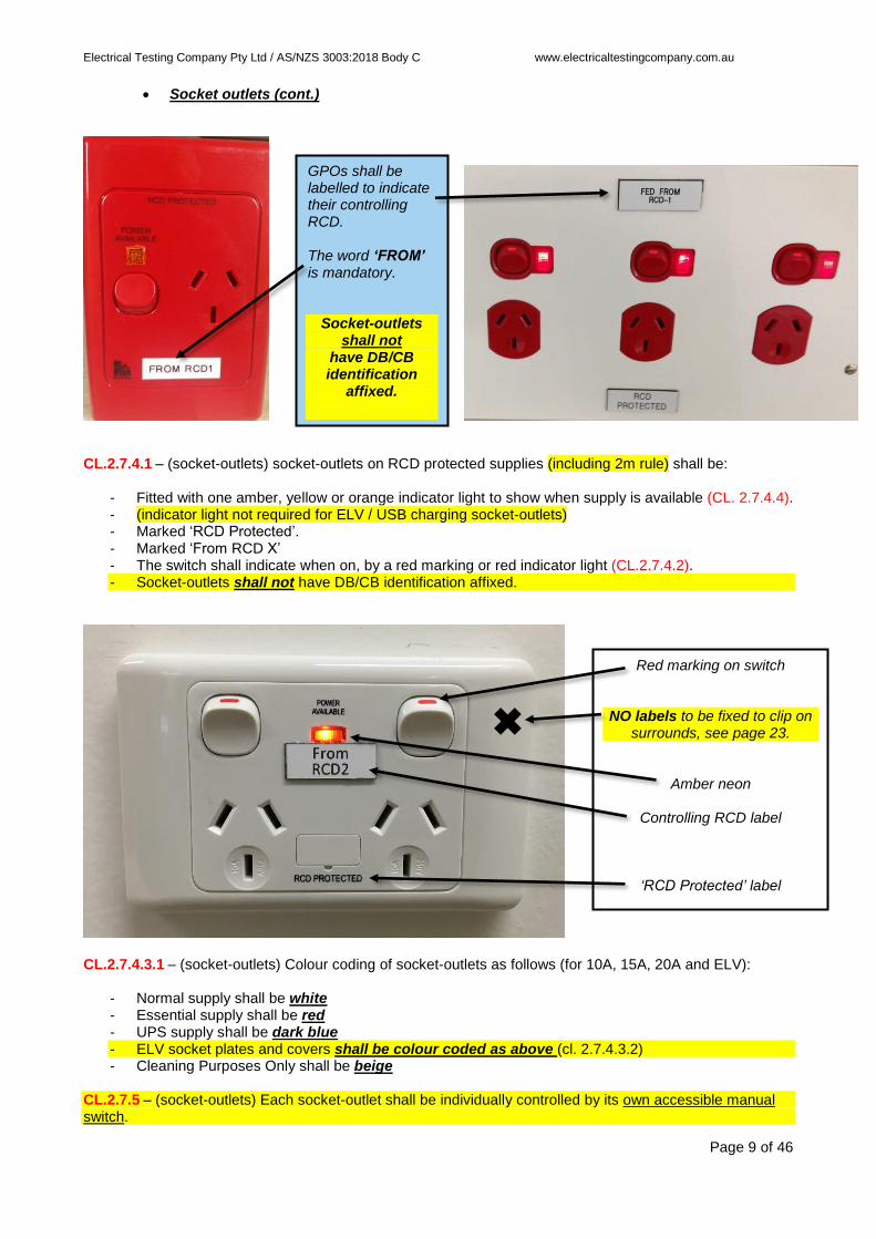
CL.2.7.4.1 – (socket-outlets) socket-outlets on RCD protected supplies (including 2m rule) shall be:
- Fitted with one amber, yellow or orange indicator light to show when supply is available (CL. 2.7.4.4). - (indicator light not required for ELV / USB charging socket-outlets) - Marked ‘RCD Protected’. - Marked ‘From RCD X’ - The switch shall indicate when on, by a red marking or red indicator light (CL.2.7.4.2). - Socket-outlets shall not have DB/CB identification affixed.
CL.2.7.4.3.1 – (socket-outlets) Colour coding of socket-outlets as follows (for 10A, 15A, 20A and ELV):
- Normal supply shall be white - Essential supply shall be red - UPS supply shall be dark blue - ELV socket plates and covers shall be colour coded as above (cl. 2.7.4.3.2) - Cleaning Purposes Only shall be beige
CL.2.7.5 – (socket-outlets) Each socket-outlet shall be individually controlled by its own accessible manual switch.
GPOs shall be labelled to indicate their controlling RCD. The word ‘FROM’ is mandatory.
Socket-outlets shall not
have DB/CB identification
affixed.
Red marking on switch
NO labels to be fixed to clip on surrounds, see page 23.
Amber neon
Controlling RCD label
‘RCD Protected’ label

Electrical Testing Company Pty Ltd / AS/NZS 3003:2018 Body C www.electricaltestingcompany.com.au
Page 10 of 46
• Protection of wiring systems
CL.2.4.2 – Wiring systems and electrical equipment that are installed in a patient area shall be adequately protected against mechanical damage in accordance with AS/NZS 3000. Ensure 30mA RCDs do not back up RCDs used in areas classified as Body protected electrical areas.
• Earthing CL.3.2 – Earthing in body-protected electrical areas shall be carried out in accordance with the requirements of AS/NZS 3000.
Therefore, a 30mA RCD cannot be used in the switchboard in lieu of mechanical protection to enable compliance to section 3.9.4 of AS/NZS 3000.

Electrical Testing Company Pty Ltd / AS/NZS 3003:2018 Body C www.electricaltestingcompany.com.au
Page 11 of 46
• Electrical Areas
CL.2.2.1 – (electrical areas) Documentation outlining patient area locations and classifications shall
be provided by the responsible organization / entity.
The documentation shall –
a) identify the location of patient areas and whether they shall be classified as body-protected, or
cardiac-protected areas;
b) identify the location of areas that are determined by the responsible organization /entity to not
be classified as patient areas (where no medical electrical equipment is used on a patient),
and shall provide justification thereof;
c) be readily available and retained at the premises;
d) be updated to record all alterations, repairs and changes of use in nominated patient areas,
and any changes of use where non-patient areas become patient areas.
Note:
Where there is doubt about the intended use of a particular location, formal clarification should be
sought from the responsible organization, and the documentation updated accordingly.
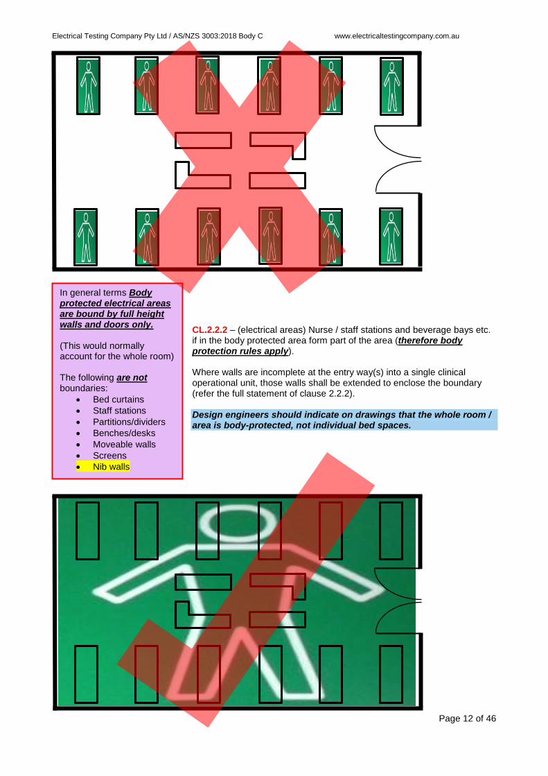
CL.2.2.2 – (electrical areas) Nurse / staff stations and beverage bays etc. if in the body protected area form part of the area (therefore body protection rules apply).
Body Protected area (includes the staff station)
In general terms Body protected electrical areas are bound by full height walls and doors only. (This would normally account for the whole room) The following are not boundaries:
• Bed curtains
• Staff stations
• Partitions/dividers
• Benches/desks
• Moveable walls
• Screens
• Nib walls
Staff / Nurse station (body protection rules shall apply to all GPOs)
Where walls are incomplete at the entry way(s) into a single clinical operational unit, those walls shall be extended to enclose the boundary (refer the full
statement of clause 2.2.2).
Electrical Testing Company Pty Ltd / AS/NZS 3003:2018 Body C www.electricaltestingcompany.com.au
Page 12 of 46
CL.2.2.2 – (electrical areas) Nurse / staff stations and beverage bays etc. if in the body protected area form part of the area (therefore body protection rules apply). Where walls are incomplete at the entry way(s) into a single clinical operational unit, those walls shall be extended to enclose the boundary (refer the full statement of clause 2.2.2). Design engineers should indicate on drawings that the whole room / area is body-protected, not individual bed spaces.
In general terms Body protected electrical areas are bound by full height walls and doors only. (This would normally account for the whole room) The following are not boundaries:
• Bed curtains
• Staff stations
• Partitions/dividers
• Benches/desks
• Moveable walls
• Screens
• Nib walls
Electrical Testing Company Pty Ltd / AS/NZS 3003:2018 Body C www.electricaltestingcompany.com.au
Page 13 of 46
• Electrical Areas (cont.) CL.2.2.4 – (electrical areas) Refer this clause for a list of locations required to be wired as body protected electrical areas – these areas may include the following:
Anaesthetic bays Audiometry A&E wards Allied health care Blood collection Chiropractic Dermatology Day procedure theatres Delivery suites Dental surgeries Doctors consult Endoscopy theatres / procedure HDU Imaging Medical & surgical wards Naturopathic Nurseries Operating theatres for non-cardiac Optometry
Outpatient exam rooms Physiotherapy Plasmapheresis Plaster rooms Procedure rooms Recovery Respiratory labs Resuscitation bays Stress test Treatment Ultrasound CL. 5.3 Disability & Aged Care Where the responsible organisation has not nominated any patient areas, the installation shall comply with AS/NZS 3000.
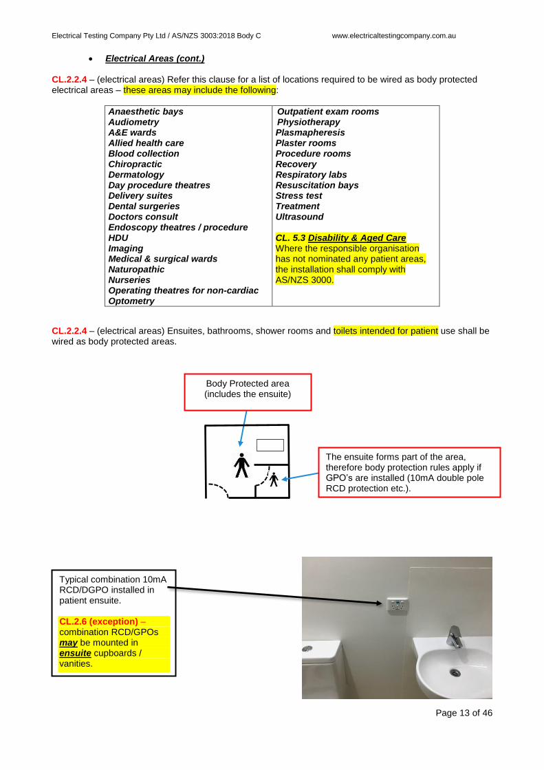
CL.2.2.4 – (electrical areas) Ensuites, bathrooms, shower rooms and toilets intended for patient use shall be wired as body protected areas.
Body Protected area (includes the ensuite)
The ensuite forms part of the area, therefore body protection rules apply if GPO’s are installed (10mA double pole RCD protection etc.).
Typical combination 10mA RCD/DGPO installed in patient ensuite. CL.2.6 (exception) – combination RCD/GPOs may be mounted in ensuite cupboards / vanities.

Electrical Testing Company Pty Ltd / AS/NZS 3003:2018 Body C www.electricaltestingcompany.com.au
Page 14 of 46
• Electrical Areas (cont.)
CL.2.12.2 – (electrical areas) Green area sign to be installed on a wall and be readily visible in the patient area, and at a height of 2m to the top of the sign.
200mm
2m to the top of the sign
FFL
90mm
2m
Top of sign FFL

Electrical Testing Company Pty Ltd / AS/NZS 3003:2018 Body C www.electricaltestingcompany.com.au
Page 15 of 46
• RCDs CL.2.4.3.2.3 – (RCDs) Socket-outlets requiring RCD protection include single phase and multi-phase LV socket-outlets of type:
- 3 pin types (including round pin earth).
- IEC industrial type with 3 to 5 round pins rated 10 to 100A. (RCD protection not required if the socket location is based on the 2m rule)
- IEC appliance type C13
CL.2.6 (a) – (RCDs) Readily accessible and no more than 2m above the floor.
CL.2.6 (b) – (RCDs) Be located in accordance with Table 2.1:
Location of protected socket or equipment Location of RCD
Within patient area Within patient area
Accessible outside a patient area Located within the area of the socket-outlet
Inaccessible outside a patient area, RCD protected (if controlling medical electrical equipment used within the patient area)
Within patient area
2m max RCDs classed as ready accessible are
to be positioned no higher than 2m, and not obstructed.
FFL
FFL

Electrical Testing Company Pty Ltd / AS/NZS 3003:2018 Body C www.electricaltestingcompany.com.au
Page 16 of 46
• RCDs (cont.)
CL.2.6(c) – (RCDs) Not mounted under benches and, RCDs must be above structures which are 1200mm or less from the ground and protrude more than 250mm out from a wall (such as a shelf).
CL.2.6(g) – (RCDs) Located 500mm from any wall mounted light switch, if near the entrance to the room.
CL.2.6 exception – (RCDs) Cleaners RCDs are excluded from the above requirements.
RCDs are to be above benches and desks for easy user access and control. Note: RCDs must be above structures which are 1200mm or less from the ground and protrude more than 250mm out from a wall (such as a shelf). Bench Not below.
RCDs must be positioned a minimum of 500mm from light switches, in any direction if near the entrance to the room. This includes network controlled light switches. (but no higher than 2m, and not obstructed)
Minimum of 500mm (switch to switch)
CL.2.6(d) be located in a visible position.

Electrical Testing Company Pty Ltd / AS/NZS 3003:2018 Body C www.electricaltestingcompany.com.au
Page 17 of 46
• RCDs (cont.)
CL.2.4.3.2.2 exception– (RCDs) Not required for GPOs mounted on a medical electrical system, for powering that system. CL.2.4.3.2.2 exception– (RCDs) Not required for GPOs above 2.3m and clearly intended for permanently mounted plug-in equipment other than medical electrical equipment. (Do not use the patient circuits in this case)
Body protected patient area typical wall elevation
2.3m
2.0m
FFL
(GPOs shown coloured red and green)
CL.2.8.1 – RCDs must be double pole (single pole switchboard busbar chassis RCDs do not comply). All active and neutral conductors are ‘live’ conductors (see note 1 of clause).
CL.2.8.3(a) – (RCDs) Supply no more than 12 points (GPOs and hard-wired equipment). CL.2.8.3(b) – (RCDs) Shall not supply points in different rooms (circuits must be dedicated to the room, see drawing page 3).
This GPO does not fall under Body protection requirements because it is above 2.3m on the wall or ceiling and is clearly intended for permanently mounted plug-in equipment. It may be protected and supplied by a sub-circuit in accordance with AS/NZS 3000. However, the rules for Body protection shall apply if supplying medical electrical equipment for patient use, and / or it is looped with GPOs in the zones below.
Inaccessible – Try to avoid placing GPOs in this zone (between
2.0m and 2.3m), as they will be classed as in the Body protection zone but they will be inaccessible and further isolation switchgear may be required.
2.3m
Body protection rules apply to a height of 2.3m from the FFL.
RCDs must isolate the neutral conductor as well as the active conductor. CL.2.8.1 – Each RCD shall be a Type 1 RCD, rated 10mA & max. trip time of 40ms. Complying with: AS/NZS 3190 AS/NZS 61008.1 AS/NZS 61009.1
Readily Accessible GPOs in this zone (FFL to 2.0m) are to be Body protected and are classed as readily accessible for clinician use, if unhindered.

Electrical Testing Company Pty Ltd / AS/NZS 3003:2018 Body C www.electricaltestingcompany.com.au
Page 18 of 46
• RCDs (cont.)
CL.2.8.4 – (RCDs) If the RCD is remote from the GPOs it controls, it shall be fitted with an amber, yellow or orange indicator light to show when supply is available to the socket outlets.
CL.2.8.5 – (RCDs) Labelled with SW/BD and MCB reference (letter height, minimum 1.5mm high), and RCD number i.e. 'RCD 1' etc. (letter height, minimum 2.0mm high). Note: The RCD reference / number shall be unique within the patient area.
CL.2.8.2 – (RCDs) 10mA RCDs shall not be backed up by 30mA RCDs.
Ensure 30mA RCDs do not back up RCDs used in areas classified as Body protected electrical areas. Ensure your switchboard builder (if applicable) does not load the busbar chassis with 30mA RCDs for classified areas under this standard. A 30mA RCD upstream of a 10mA RCD will not provide adequate discrimination. Therefore, a 30mA RCD cannot be used in the switchboard in lieu of mechanical protection. – refer section 3.9 of AS/NZS 3000, clause 3.9.4.3.2 and 3.9.4.4.
CL.2.12.1- Labelling shall not be fixed to removable surrounds of RCDs or socket-outlets unless duplicate identification is permanently affixed to the body of the RCD or socket-outlet and visible when the surround is removed. The label maybe adjacent, e.g. on the wall.
Amber indicator light to show supply available to GPOs.
RCD number label
SW/BD MCB label

Electrical Testing Company Pty Ltd / AS/NZS 3003:2018 Body C www.electricaltestingcompany.com.au
Page 19 of 46
• Testing and Verification
CL.2.13 – (Testing and verification) Prior to placing an electrical installation into service, it shall be inspected, tested and verified, that the installation is safe to energize and complies with the requirements of AS/NZS 3000 and AS/NZS 3003. Verification is defined as being the confirmation, corroboration, proof, substantiation, authentication and certification of an electrical installation following construction, alteration, addition or repair. The electrical installation shall be –
✓ Inspected as far as is practicable; and
✓ Tested and verified in accordance with Appendix B (Commissioning Inspection Checklist) of AS/NZS 3003
Normally carried out by an independent body with defined experience and certified, compliant and calibrated electrical testing equipment and regime.
; and
✓ Tested in accordance with AS/NZS 3000.
Verification documentation: The electrical installation worker / contractor will provide a written statement of compliance. See next page for statement template. This form needs to be completed and handed to the person responsible for final verification prior to inspection and electrical testing against the requirements of AS/NZS 3003.
Contact: Electrical Testing Company Pty Ltd Unit 15, 10 Victoria Ave Castle Hill NSW 2154 T: 02 8850 1380 F: 02 8850 1384 E: [email protected]

Electrical Testing Company Pty Ltd / AS/NZS 3003:2018 Body C www.electricaltestingcompany.com.au
Page 20 of 46
Statement of Conformity with AS/NZS 3003
Cardiac-protected electrical area New patient area Body-protected electrical area Alteration or addition to electrical installation Repair to electrical installation
Institution: ……………………………………………………………………………………………………………………………………………….. Address: …………………………………………………………………………………………………………………………………………………… Location: ………………………………………………………………………………………………………………………………………………….. Description of electrical work: …………………………………………………………………………………………………………………. …………………………………………………………………………………………………………………………………………………………………. Date completed: ………………………………………………… Date of statement: …………………………………………………….. I, the licensed electrical installation worker, who carried out the work described above, states that:
• The work has passed all the required tests and conforms in all O Yes O No O N/A
respects with the current edition of AS/NZS 3000.
• The work has followed a formal specification prepared by or on O Yes O No O N/A
behalf of the health care institution or practice.
• I/We have discussed the number of socket-outlets required with O Yes O No O N/A
the medical or nursing personnel who will be responsible for work in each area and verified the likely loading on each circuit.
• I/We have verified that the isolation transformer, line isolation O Yes O No O N/A
monitor and overload monitor comply with AS/NZS 4510.
• I/We are in possession of manufacturers’ statement(s) of O Yes O No O N/A
compliance or have otherwise verified that each ELV supply conforms with a suitable standard ensuring double insulation from LV supplies.
Name: ………………………………………………………………………………………………………………………………………………………………………….. Company: …………………………………………………………………………………………………………………………………………………………………….. Address: ……………………………………………………………………………………………………………………………………………………………………….. ………………………………………………………………………………………………………………………………………………………………………………………
Signed: ………………………………………………………………………….. Electrical licence number: …………………………………………..

Electrical Testing Company Pty Ltd / AS/NZS 3003:2018 Body C www.electricaltestingcompany.com.au
Page 21 of 46
• Definitions
CL.1.5.2 – Applied part. Part of medical electrical equipment (ME) that in normal use necessarily comes into physical contact with the patient for ME equipment or an ME system to perform its function.
- Type B (non-isolated, equipment has a protective earth terminal)
- Type BF (floating, equipment is separated from earth)
- Type CF (floating, equipment is separated from earth)
CL.1.5.16 - Medical electrical equipment (ME equipment) Electrical equipment having an ‘applied part’ for transferring energy to or from the patient or detecting such energy transfer to or from the patient and which is –
a) Provided with not more than one connection to a particular supply mains, and b) Is intended by its manufacturer to be used – in diagnosis, treatment or monitoring of a patient, or - for compensation or alleviation of disease, injury or disability.
CL.1.5.24 - 'Readily accessible'. Capable of being reached quickly and without climbing onto or over any object, or removing obstructions, and in any case not more than 2m above the ground, floor or platform.
This electrical standard is quite specific in that the body-protected electrical areas medical electrical equipment must be in the control of the clinician within the area:
• The clinician must be able to access all the electrical controlling switchgear to enable isolation of socket-outlets and resetting of RCDs.
• The clinician is unable to reach above 2 metres.
• The clinician cannot by accident turn off RCDs when switching light circuits.
• The clinician is unable to reach below benches or desks or enter cupboards to reset RCDs.
• The clinician is unable to move bulky equipment to access GPOs and RCDs.
• The clinician may not use a ladder or chair for standing on to access GPOs.
• So therefore, RCDs must be positioned below 2 metres but above benches or desks, and at least 500mm from a light switch.
• So therefore, socket-outlets located behind bulky equipment must have an accessible double pole isolator.
• So therefore, socket-outlets behind or inhibited by flat screen monitors must have an accessible double pole isolator.
• So therefore, socket-outlets above 2 metres which are looped with other socket outlets in the area below 2 metres must have an accessible
double pole isolator below 2 metres. • A dedicated RCD for an inhibited or inaccessible
socket outlet requires a readily accessible test facility (round pin earth, white GPO).

Electrical Testing Company Pty Ltd / AS/NZS 3003:2018 Body C www.electricaltestingcompany.com.au
Page 22 of 46
• Cleaners socket-outlets
CL.2.4.1.3 – (cleaner GPO) Shall not be supplied from any final sub-circuit supplying other sockets in the area. CL.2.7.4.3.1(d) – (cleaner GPO) Colour beige, marked 'Cleaning Purposes Only' (letter height minimum 5.0mm high)
CL.2.7.3.1(a) – (cleaner GPO) Body protected electrical area – one placed within the area or within 15m of the area (see drawing page 8). Exception – socket-outlets for cleaning equipment are not required in MRI scanning rooms. CL.2.7.3.2 – (cleaner GPO) Shall be RCD protected, this RCD shall only protect these sockets.
CL.2.8.1 – Cleaner RCD must be 10mA and double pole. (Good practise is to install these RCDs within the switchboard area/cupboard for easy reset by hospital staff), (note - single pole switchboard busbar chassis RCDs do not comply)
All RCDs associated with this standard shall be double pole, including cleaners RCDs, which shall also be 10mA. Ensure your switchboard builder (if applicable) supplies you with double pole RCDs.

Electrical Testing Company Pty Ltd / AS/NZS 3003:2018 Body C www.electricaltestingcompany.com.au
Page 23 of 46
• Marking / Labelling
CL.2.12.1(ii) – (labels) DB/CB identification labels for RCDs shall be not less than 1.5mm for the lettering height. CL.2.12.1(iii) – (labels) RCD identification for RCDs shall be not less than 2.0mm for the lettering height. CL.2.12.1(A) – (labels) Portable adhesive tape labels (Brother type) shall include a clear top laminate overlay in order to protect the printed lettering (tape labels without the laminate overlay are not acceptable).
RCD ID minimum 2mm letter height
DB/CB ID minimum 1.5mm letter height
Tape labels must have a clear top laminate overlay.
RCD number label
SW/BD MCB label
Socket-outlets to be labelled with their controlling RCD: ‘From RCD X’
CL.2.12.1 - Labelling shall not be fixed to removable surrounds of RCDs or socket-outlets unless duplicate identification is permanently affixed to the body of the RCD or socket-outlet and visible when the surround is removed. The label maybe adjacent, e.g. on the wall.

Electrical Testing Company Pty Ltd / AS/NZS 3003:2018 Body C www.electricaltestingcompany.com.au
Page 24 of 46
• Permanently-wired medical electrical equipment requiring LPD protection CL.2.4.3.3 – Permanently wired medical electrical equipment with any of the following Type B applied parts –
a. electrodes or transducers that contact patients; b. that enter patients; c. that contact liquid that enter patients
- shall be RCD protected (10mA double pole).
The supply to other permanently wired equipment shall be protected as required in AS/NZS 3000.
CL.2.8.6 - If a dedicated RCD is connected to permanently wired equipment, a white round earth pin GPO shall be provided in an accessible position to enable testing of the RCD, and labelled 'Test Only'. The RCD shall be labelled to identify the equipment it controls.
(labelled)
TEST ONLY
Typical medical electrical equipment specification page, indicating the equipment is classified as Type B – degree of protection against electrical shock. The corresponding rating plate with the ‘Type B’ symbol.

Electrical Testing Company Pty Ltd / AS/NZS 3003:2018 Body C www.electricaltestingcompany.com.au
Page 25 of 46
(information) The patient electrical area classifications of ASNZS 3003 (Electrical installations – Patient areas) is based on the application of medical electrical equipment as defined in ASNZS 3200 (Medical electrical equipment) and referenced in ASNZS 2500 (Guide to the safe use of electricity in patient care). ASNZS 3200 defines medical electrical equipment with conductive ‘applied parts’ i.e. electrical connections to the patient, into the following classes:
- Type B (non-isolated, equipment has a protective earth terminal)
- Type BF (floating, equipment is separated from earth)
- Type CF (floating, equipment is separated from earth)
ASNZS 3003 defines patient areas as locations where it is intended that low-voltage medical electrical equipment will be used in contact with patients while connected to the electrical supply mains. ASNZS 3003 states that all patient areas shall be:
- Body-protected electrical areas
or
- Cardiac-protected electrical areas
Note: Standards may change, including the adoption of the IEC equivalent

Electrical Testing Company Pty Ltd / AS/NZS 3003:2018 Body C www.electricaltestingcompany.com.au
Page 26 of 46
(information) There is a direct correlation between the patient area electrical classification (ASNZS 3003) and the type of medical procedure (ASNZS 2500) when using medical electrical equipment applied parts (ASNZS 3200) in contact with patients, categorized as follows:
AS/NZS 3200 Medical Equipment –
Applied Part
AS/NZS 2500 Medical Procedure Type
AS/NZS 3003 Patient Electrical Area
Type B Body Body-protected
Type BF Body Body-protected
Type CF Cardiac Cardiac-protected
Body-type medical procedures as defined by ASNZS 2500:
- (summation) Applied parts not involving the heart, a patient is considered to be undergoing a body-
type procedure when connected to a piece of medical electrical equipment in such a manner that the
impedance of the skin is either reduced by electrode paste or gel, or by-passed by the entrance of
conducting fluids, metal needles, saline-filled catheters and similar, through natural or artificial
openings in the patient’s body, but where direct contact with the heart is not possible.
Cardiac-type medical procedure as defined by ASNZS 2500:
- (summation) Applied parts involving the heart, a patient is considered to be undergoing a cardiac-
type procedure when an in dwelling electrical conductor is accessible outside the patient’s body and
there is risk of microshock. In this context, an electrical conductor includes electrical wires, such as
cardiac-pacing electrodes and intracardiac ECG electrodes, intracardiac catheters, or intracardiac
insulated tubes filled with conducting fluids.
ASNZS 2500 defines the following protection levels against electric shock for electrical wiring in patient areas:
- (summation) Body-protected electrical area: where parts of medical electrical equipment are
fastened to parts of a patient other than the heart, the use of a RCD or an isolation transformer with
LIM monitor will ensure, that if any contact is made between a live conductor and earth (either
directly or as a function of leakage currents), ‘macroshock electrocution’ is very unlikely.
- (summation) Cardiac-protected electrical area: where the procedure involves direct connection to the
heart, RCD or isolation transformer protection, similar to that required for a body-protected electrical
area, is supplemented with special earthing facilities to also provide protection against ‘microshock
electrocution’. Such a system not only protects against any fault or leakage currents posing a
macroshock hazard, but also reduces the potential difference appearing between any conducting
surfaces in the vicinity of the patient (electrically-operated equipment, plumbing, structural metal and
similar) to a level well below that which would produce microshock electrocution.

Electrical Testing Company Pty Ltd / AS/NZS 3003:2018 Body C www.electricaltestingcompany.com.au
Page 27 of 46
(information) This document has been produced to clear some confusion with respect to whether certain ceiling mounted electrical-operated equipment in Body and Cardiac protected electrical areas are required to have accessible 10mA RCD protection located in the protected electrical area, specifically supplies for electrical-operated equipment such as examination lights and monitor arms. This type of equipment typically does not have conductive ‘applied parts’ electrical connections to the patient, so therefore it is not included in the definition for medical electrical equipment as described above under standards ASNZS3200, ASNZS 2500 and ASNZS 3003. The supply power LV is normally located in the ceiling space and may be a power socket. This power socket may be protected by an RCD located at the switchboard and be rated at 30mA. The supply power is typically transformed from LV to ELV before entering the patient area. This condition would be suitable for a body-protected electrical area without further protection. However, if the equipment is to be located in a cardiac-protected electrical area the addition of supplementary bonding is required. Such earthing is achieved by connecting the protective earth terminal to the EP junction (if protectively earthed equipment). For non-protectively earthed parts, such earthing is achieved by connecting the mounting point of the equipment or the point in which it contacts structural metal to the EP junction. The equipotential bonding (cardiac area) of the equipment would be tested and certified as part of the ASNZS 3003 commissioning process. On the flip-side, contractors need to be aware of the type of electrical equipment, especially fixed electrical equipment they are terminating in body and cardiac protected electrical areas.
If the fixed electrical equipment is classified as medical electrical equipment with applied parts Type B , all aspects of ASNZS 3003 are applicable, clause 2.4.3.3 specifically, and 10mA RCD protection is required including an RCD test point being a round earth pin white GPO. ASNZS 3003 does not mention the same requirements for fixed medical electrical equipment with applied
parts Type BF and Type CF .
Type BF and Type CF fixed medical electrical equipment would also fall under the installation requirements of ASNZS 3000, but supplementary bonding (ASNZS 3003) may be applicable in cardiac areas if the equipment contacts structural metal.
If the fixed electrical equipment is not medical electrical equipment with applied parts Type B , ASNZS 3000 requirements are applicable, unless in a cardiac-protected electrical area then supplementary bonding (ASNZS 3003) may be required. CL. 2.10 – where permanently wired electrical equipment is supplied from an RCD that also supplies socket-outlets or other equipment, the electrical equipment shall be provided with a separate, individual, readily accessible double pole isolation switch. Not readily accessible GPOs shall be treated in the same manner.

Electrical Testing Company Pty Ltd / AS/NZS 3003:2018 Body C www.electricaltestingcompany.com.au
Page 28 of 46
• Installations for self - harm patients (intentional or unintentional) CL.5.4.1 – (self-harm) Areas intended for the care of patients who are susceptible to self-harm shall be wired as body-protected electrical areas, except for the following: CL.5.4.1(a) – (self-harm) RCDs shall be located in an area readily accessible only to staff, e.g. at the staff station.
CL.5.4.1(b) – (self-harm) Socket-outlet power available neons need not be provided. CL.5.4.1(c) – (self-harm) The RCD shall be fitted with an amber light indicator, fed from the load side of the RCD. CL.5.4.1(d) – (self-harm) The colour requirements of socket-outlets need not apply. CL.5.4.2 – (self-harm) RCDs located outside the patient area shall be labelled with the bed number.
CL.5.4.2 – (self-harm) Area signs should be located immediately outside the entrance to the patient area, external to the room. CL.5.4.2 – (self-harm) Area signs shall be securely fixed as high as practicable.
Bed number label Group of RCDs located at the staff station
SW/BD MCB number label
Amber neon connected load
side
As high as practicable.
.
Must be securely fixed
FFL

Electrical Testing Company Pty Ltd / AS/NZS 3003:2018 Body C www.electricaltestingcompany.com.au
Page 29 of 46
• Alterations, additions and repairs (shall comply with Section 6 of the standard) CL. 6.2.1 – (alterations and additions) Every alteration of, or addition to, the electrical installation in an existing patient area shall comply with the relevant provisions of AS/NZS 3003: 2018. This requirement applies to all alterations and additions, ranging from the install of new socket-outlets to the installation or replacement of fixed electrical equipment such as dental chairs and CT scanners. CL. 6.2.2 – (alterations and additions) Patient areas that are not already signposted as body-protected or cardiac protected electrical areas shall be upgraded to comply with AS/NZS 3003: 2018, prior to or during the alteration or addition to the electrical installation, or to permanently wired equipment. Separate circuits to patient areas need not apply to alterations to areas not wired as body-protected electrical areas. Old signs indicating CLASS A or CLASS B areas are not body or cardiac protected areas. CL. 6.2.3 – (alterations and additions) Alterations or additions to electrical installations in patient areas shall not proceed unless the patient area has been subjected to routine testing within the previous 12 months. The green area sign shall have a current in-date sticker attached, if not the area needs to be retested prior to the works. CL. 6.2.4 – (alterations and additions) If the installation of additional socket-outlets in a patient area increases the overall number by more than 10%, all socket outlets shall comply with the colour coding requirements of AS/NZS 3003: 2018, clause 2.7.4.3.
a) White – normal supply b) Red – essential supply c) Blue – UPS
CL. 6.2.5.1 – (alterations and additions) IN CARDIAC Protected electrical areas the following requirements shall be applied prior to the alteration:
1. Where the EP junction cannot be identified, or is inaccessible for new connections, the entire EP earthing system shall be upgraded to comply with AS/NZS 3003: 2018.
2. Where the EP junction or EP test point is not marked ‘EP TEST POINT’ an EP test facility shall be installed to comply with clause 4.4.2.9.
3. If the EP test point is remote from the EP junction the linking cable shall be sized to ensure the
resistance measurements comply with the standard.
4. New EP earthing connections shall comply with this standard when installing new electrical accessories, fixed equipment rated below 2.0kW, and non-electrical structural metal connected fittings.
CL.6.2.5.2 – Where fixed electrical equipment rated at or above 2.0kW is to be installed in a body-protected or cardiac-protected electrical area, the entire patient area shall comply with AS/NZS 3003: 2018 prior to or during alteration or addition to the electrical installation. CL.6.2.5.3 – If cardiac-protected areas are to be reclassified as body-protected areas, they shall comply with sections 2 and 3. Have all EP studs or receptacles removed and be tested and verified. CL. 6.3.1 – (repairs) Patient areas that are not wired as cardiac or body-protected electrical areas should be upgraded to comply with AS/NZS 3003, prior to or immediately after repairs of RCDs and socket outlets or permanently wired electrical equipment. (The requirement for separate circuits need not apply to repairs CL.2.4.1)

Electrical Testing Company Pty Ltd / AS/NZS 3003:2018 Body C www.electricaltestingcompany.com.au
Page 30 of 46
Alterations, additions and repairs (cont.) CL. 6.3.2 – (repairs) Patient areas wired as cardiac or body-protected shall have a current test sticker attached to the area sign before repairs proceed. If the methods satisfy the fundamental safety principles of Part 1 AS/NZS 3000 the following work may be carried out to electrical installations with the original install method:
• Repairs to or replacement of accessories (as defined in AS/NZS 3000) forming part of the existing electrical installation or replacement of such accessories with equivalent fittings.
• Replacement of component parts of fixed equipment with equivalent components. Replacement of a complete item of fixed electrical equipment in a patient area constitutes an alteration to the electrical installation and shall comply with clause 6.2. The replaced item shall be tested against the applicable compliance requirements of this standard. CL.6.4 – Where alterations occur, a label shall be added below the routine test label stating that alterations have occurred and indicating the report number, date, name of test person, organization responsible and contact details. The label shall not cover any existing labels and shall be removed at the time of the next routine inspection.
Alteration Report No.: Date: Tested by: Organisation: Contact details:
Routine Electrical Safety Test label
Certification and Verification label at
time of original commissioning
Label to be installed at time of alteration, addition or repair to the body-protected electrical area.

Electrical Testing Company Pty Ltd / AS/NZS 3003:2018 Body C www.electricaltestingcompany.com.au
Page 31 of 46
Body-protected patient area – typical wall elevation ‘A’
2.3m
2.0m
FFL
Body-protected GPOs shown coloured red RCD shown coloured black
The 500mm separation also applies to network controlled light switches.
RCDs must be positioned a minimum of 500mm in any direction from a light switch (CL.2.6g) and be below 2.0m, visible and readily accessible.
2.3m
Body protection rules apply to a height of 2.3m from the FFL.
Entrance to room
Minimum 500mm separation (switch to switch)
500mm

Electrical Testing Company Pty Ltd / AS/NZS 3003:2018 Body C www.electricaltestingcompany.com.au
Page 32 of 46
Body-protected patient area – typical wall elevation ‘B’
2.3m
2.0m
FFL
Body-protected GPOs shown coloured red Double-pole isolator shown coloured blue
AS/NZS 3000 protected GPO shown coloured green
Body-protected patient area – typical wall elevation ‘C’
2.3m
2.0m
FFL
Body-protected GPOs shown coloured red Double-pole isolator shown coloured blue
Double pole isolator controlling the red GPO above 2.0m.
This GPO is classed as inaccessible as it is positioned above 2.0m (CL.1.5.25). It therefore requires a double-pole isolator (CL.2.7.2) positioned below 2.0.m to enable isolation by the controlling clinician.
2.3m
Body protection rules apply to a height of 2.3m from the FFL.
To the controlling RCD
In this case the design engineer has requested the examination light be hard-wired to the body-protected GPO circuit. Therefore, a double pole isolator is required to control the hard-wired equipment (CL.2.10). The isolator must be below 2.0m.
2.3m
Body protection rules apply to a height of 2.3m from the FFL.
GPO for non-medical permanent fixed equipment (CL.2.4.3.2.2a1) such as a TV, as it is above 2.3m it may be protected in accordance with AS/NZS 3000.
To the controlling RCD
Electrical Testing Company Pty Ltd / AS/NZS 3003:2018 Body C www.electricaltestingcompany.com.au
Page 33 of 46
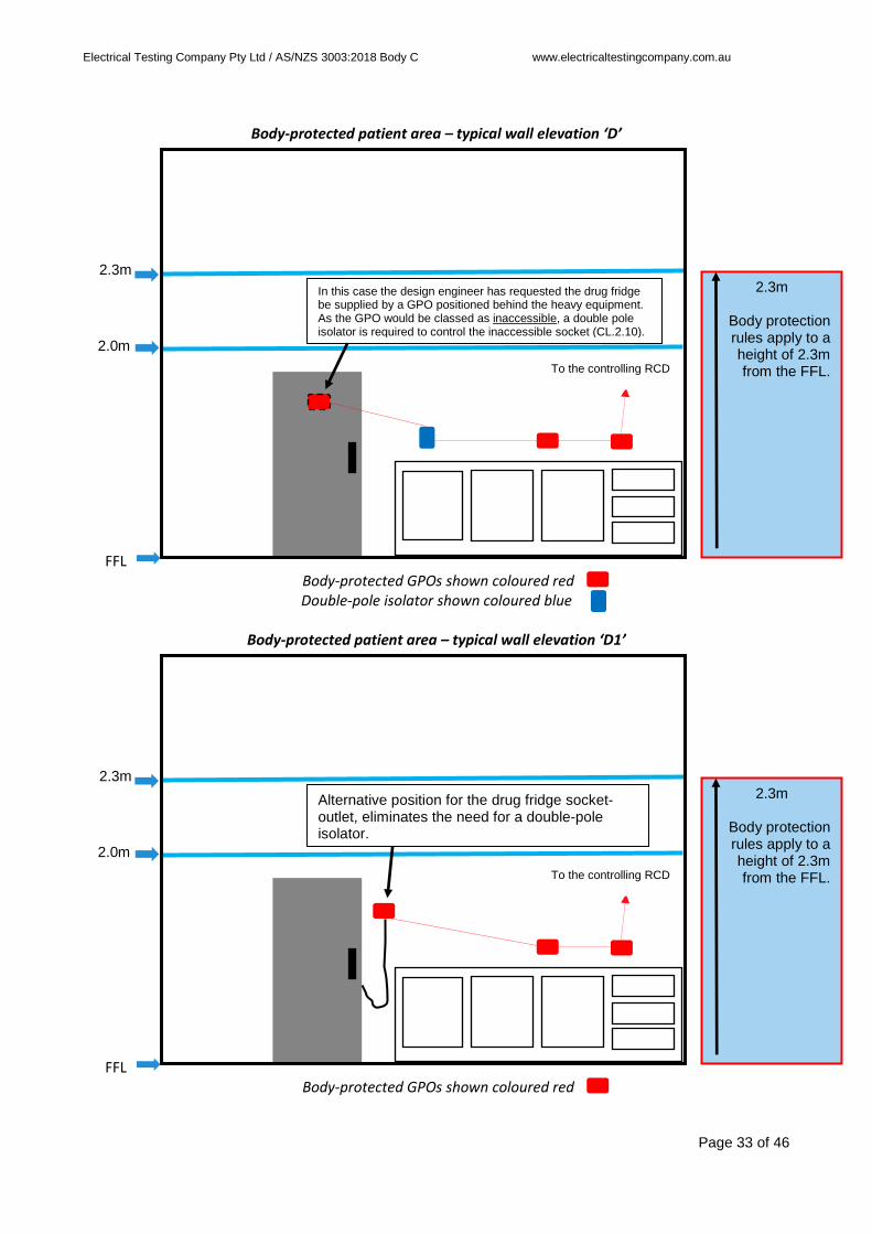
Body-protected patient area – typical wall elevation ‘D’
2.3m
2.0m
FFL
Body-protected GPOs shown coloured red Double-pole isolator shown coloured blue
Body-protected patient area – typical wall elevation ‘D1’
2.3m
2.0m
FFL
Body-protected GPOs shown coloured red
In this case the design engineer has requested the drug fridge be supplied by a GPO positioned behind the heavy equipment. As the GPO would be classed as inaccessible, a double pole isolator is required to control the inaccessible socket (CL.2.10).
2.3m
Body protection rules apply to a height of 2.3m from the FFL.
To the controlling RCD
Alternative position for the drug fridge socket-outlet, eliminates the need for a double-pole isolator.
2.3m
Body protection rules apply to a height of 2.3m from the FFL.
To the controlling RCD
Electrical Testing Company Pty Ltd / AS/NZS 3003:2018 Body C www.electricaltestingcompany.com.au
Page 34 of 46
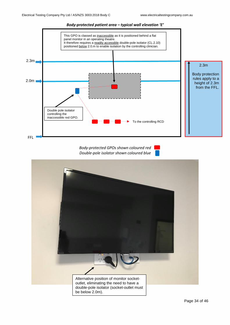
Body-protected patient area – typical wall elevation ‘E’
2.3m
2.0m
FFL
Body-protected GPOs shown coloured red Double-pole isolator shown coloured blue
Double pole isolator controlling the inaccessible red GPO.
Alternative position of monitor socket-outlet, eliminating the need to have a double-pole isolator (socket-outlet must be below 2.0m).
This GPO is classed as inaccessible as it is positioned behind a flat panel monitor in an operating theatre. It therefore requires a readily accessible double-pole isolator (CL.2.10) positioned below 2.0.m to enable isolation by the controlling clinician.
2.3m
Body protection rules apply to a height of 2.3m from the FFL.
To the controlling RCD

Electrical Testing Company Pty Ltd / AS/NZS 3003:2018 Body C www.electricaltestingcompany.com.au
Page 35 of 46
Body-protected patient area – typical wall elevation ‘F’
2.3m
2.0m
FFL
Body-protected GPOs shown coloured red Double-pole isolator shown coloured blue
Body-protected patient area – typical wall elevation ‘F1’
2.3m
2.0m
FFL
Body-protected GPOs shown coloured red
The drug fridge is supplied by a GPO positioned behind the heavy equipment. As the GPO would be classed as inaccessible, a double pole isolator is required to control the inaccessible socket (CL.2.10).
2.3m
Body protection rules apply to a height of 2.3m from the FFL.
To the controlling RCD
Alternative position for the drug fridge socket-outlet, eliminates the need for a double-pole isolator, as long as the GPO is not obstructed inside the cupboard and the door is not locked.
To the controlling RCD
2.3m
Body protection rules apply to a height of 2.3m from the FFL.

Electrical Testing Company Pty Ltd / AS/NZS 3003:2018 Body C www.electricaltestingcompany.com.au
Page 36 of 46
Body-protected patient area – typical wall elevation ‘G’
2.3m
2.0m
FFL
Body-protected GPOs shown coloured red Double-pole isolator shown coloured blue
Body-protected patient area – typical wall elevation ‘H’
2.3m
2.0m
FFL
Body-protected GPOs shown coloured red Double-pole isolator shown coloured blue
The X-ray viewing screen is hard-wired to the body-protected GPO circuit. Therefore, a double pole isolator is required to control this X-ray viewer (CL.2.10). Isolators should be independent of the equipment they are controlling. Hard-wired equipment is to be counted as one point when counting the number of points associated with an RCD.
To the controlling RCD
2.3m
Body protection rules apply to a height of 2.3m from the FFL.
The patient monitor is supplied by a GPO positioned above 2.0m. Therefore, a double pole isolator is required (CL.2.10) to control this GPO. The isolator must be below 2.0m.
To the controlling RCD
2.3m
Body protection rules apply to a height of 2.3m from the FFL.

Electrical Testing Company Pty Ltd / AS/NZS 3003:2018 Body C www.electricaltestingcompany.com.au
Page 37 of 46
Body-protected patient area – typical wall elevation ‘I’
2.3m
2.0m
FFL
Body-protected GPO shown coloured red RCD shown coloured black
Double-pole isolator shown coloured blue
Body-protected patient area – typical wall elevation ‘J’
2.3m
2.0m
FFL
Body-protected GPO shown coloured red RCDs shown coloured black
RCDs must be positioned a minimum of 500mm in any direction from a light switch and be below 2.0m, visible and readily accessible.
2.3m
Body protection rules apply to a height of 2.3m from the FFL.
500mm
Dental chairs hard-wired to the body-protected GPO circuit require a double-pole isolator (CL.2.10).
Entrance to room
2.3m
Body protection rules apply to a height of 2.3m from the FFL.
Entrance to room
500mm
Entrance to room
In this case the design engineer requires the dental chair to be protected by a dedicated 10mA RCD (CL.2.8.6). This will require a round-pin earth white GPO positioned near the RCD to enable testing of the RCD (CL2.8.7).

Electrical Testing Company Pty Ltd / AS/NZS 3003:2018 Body C www.electricaltestingcompany.com.au
Page 38 of 46
Body-protected patient area – typical wall elevation ‘K’
2.3m
2.0m
FFL
RCD shown coloured black
Body-protected patient area – typical wall elevation ‘L’
2.3m
2.0m
FFL
RCD shown coloured black
Body-protected GPO shown coloured red
In this case the design engineer has requested the drug fridge be supplied by a GPO positioned behind the heavy equipment. The GPO is supplied by a dedicated 10mA RCD. As the GPO would be classed as inaccessible, a test facility shall be provided to enable testing of the RCD (CL.2.7.2).
2.3m
Body protection rules apply to a height of 2.3m from the FFL.
(CL.2.4.3.3)10mA RCD protection shall be provided for permanently-wired medical electrical equipment (MEE) with any of the following Type B applied parts:
- electrodes or transducers that contact patients;
- that enter patients; - that contact liquid that enters
patients. A test facility shall be provided to enable testing of the RCD (CL.2.8.7).
2.3m
Body protection rules apply to a height of 2.3m from the FFL.
RCD test facility
MEE
Entrance to room
MEE

Electrical Testing Company Pty Ltd / AS/NZS 3003:2018 Body C www.electricaltestingcompany.com.au
Page 39 of 46
Body-protected patient area – typical wall elevation ‘M’
2.3m
2.0m
FFL
Body-protected GPOs shown coloured red RCDs shown coloured black
Body-protected patient area – typical wall elevation ‘N’
2.3m
2.0m
FFL
RCDs shown coloured black
Body-protected GPOs shown coloured red
RCDs must not be positioned below structures that protrude more than 250mm out from the wall and less than 1200mm from the FFL (CL.2.6c).
2.3m
Body protection rules apply to a height of 2.3m from the FFL.
Entrance to room
1200mm
RCDs shall not be in cupboards or cabinets (CL.2.6e).
2.3m
Body protection rules apply to a height of 2.3m from the FFL.

Electrical Testing Company Pty Ltd / AS/NZS 3003:2018 Body C www.electricaltestingcompany.com.au
Page 40 of 46
Body-protected patient area – typical wall elevation ‘O’
2.3m
2.0m
FFL
Body-protected GPO shown coloured red RCD shown coloured black
Double-pole isolator shown coloured blue
Isolation switches shall not be located within 500mm of the light switch at the entrance of the room (CL.2.7.2).
Entrance to room
500mm
2.3m
Body protection rules apply to a height of 2.3m from the FFL.
Incorrect, the TV socket-outlet isolation switch must be a minimum of 500mm from the light switch.

Electrical Testing Company Pty Ltd / AS/NZS 3003:2018 Body C www.electricaltestingcompany.com.au
Page 41 of 46
Body-protected patient area – typical wall elevation ‘P’
2.3m
2.0m
FFL
RCDs shown coloured black Body-protected GPOs shown coloured red Double-pole isolator shown coloured blue
In this elevation an operating theatre imaging data rack is shown. Ensure the controlling RCDs are not placed inside the cabinet (CL.2.6e).
Ensure GPOs are positioned on the side of the cabinet towards the front, if they are located at the rear they will be classed as inaccessible and further isolation switchgear may be required (CL2.7.2).
2.3m
Body protection rules apply to a height of 2.3m from the FFL.
Socket-outlets readily accessible on the side of cabinet towards the front, not obstructed and below 2m.
RCD external to the cabinet in a visible position.
In this situation the GPO positioned above 2.0m still requires a double pole isolator located below 2.0m (CL.2.7.2).
Electrical Testing Company Pty Ltd / AS/NZS 3003:2018 Body C www.electricaltestingcompany.com.au
Page 42 of 46
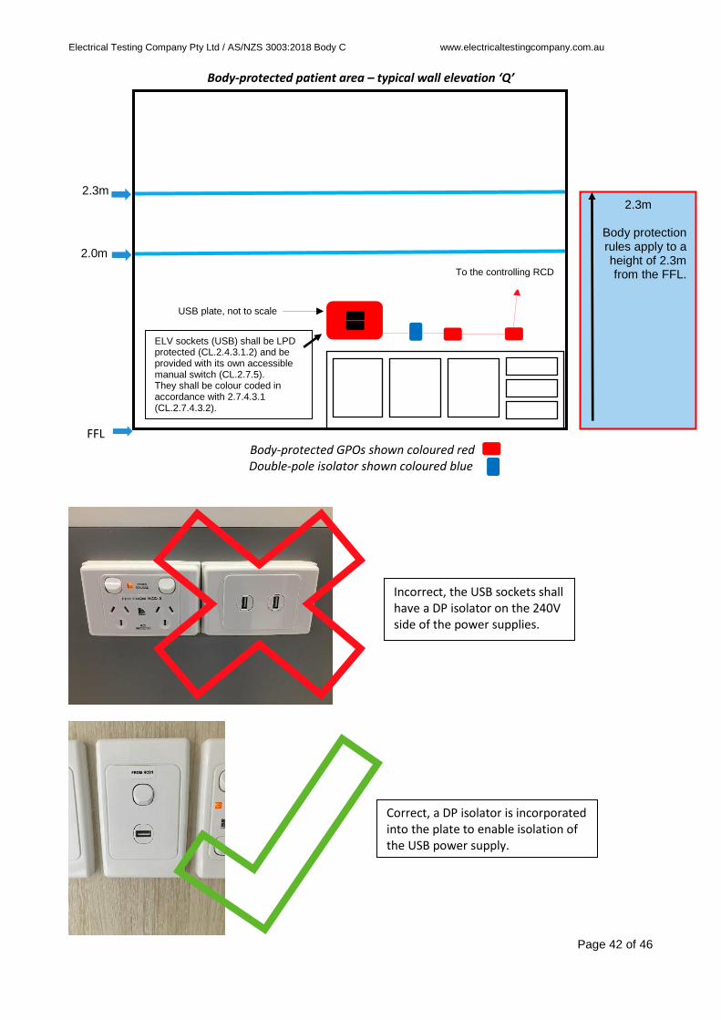
Body-protected patient area – typical wall elevation ‘Q’
2.3m
2.0m
FFL
Body-protected GPOs shown coloured red Double-pole isolator shown coloured blue
ELV sockets (USB) shall be LPD protected (CL.2.4.3.1.2) and be provided with its own accessible manual switch (CL.2.7.5). They shall be colour coded in accordance with 2.7.4.3.1 (CL.2.7.4.3.2).
USB plate, not to scale
Incorrect, the USB sockets shall have a DP isolator on the 240V side of the power supplies.
Correct, a DP isolator is incorporated into the plate to enable isolation of the USB power supply.
2.3m
Body protection rules apply to a height of 2.3m from the FFL.
To the controlling RCD

Electrical Testing Company Pty Ltd / AS/NZS 3003:2018 Body C www.electricaltestingcompany.com.au
Page 43 of 46
Body-protected patient area – typical wall elevation ‘R’
2.3m
2.0m
FFL
Body-protected GPOs shown coloured red Double-pole isolator shown coloured blue
AS/NZS 3000 protected GPO shown coloured green
Body-protected patient area – typical wall elevation ‘S’
2.3m
2.0m
FFL
RCD shown coloured black Body-protected GPOs shown coloured red Double-pole isolators shown coloured blue
(CL.2.8.3) In a body-protected area with multiple patient locations, one RCD may protect multiple patient locations to a maximum of 12 points (combination of socket-outlets and hard-wired equipment).
2.3m
Body protection rules apply to a height of 2.3m from the FFL.
The ZIP hot water service may be protected in accordance with AS/NZS 3000 as long as the cupboard door is locked (CL.2.4.3.2.2a).
2.3m
Body protection rules apply to a height of 2.3m from the FFL.
To the controlling RCD

Electrical Testing Company Pty Ltd / AS/NZS 3003:2018 Body C www.electricaltestingcompany.com.au
Page 44 of 46
Cardiac-protected patient area – typical wall elevation ‘T’
2.3m
2.0m
FFL
RCDs shown coloured black Cardiac-protected GPOs shown coloured red
Double-pole isolators shown coloured blue
Body-protected patient area – typical wall elevation ‘U’
2.3m
2.0m
FFL
Body-protected GPOs shown coloured red Double-pole isolators shown coloured blue
2.3m
Body protection rules apply to a height of 2.3m from the FFL.
To the controlling RCD at the staff station (CL.5.4.1a).
2.3m
Cardiac-protection rules apply to a height of 2.3m from the FFL.
INSTALATION FOR SELF-HARM PATIENTS (CL.5.4) In this case the design engineer requires the bed-side lamp and the television to be plugged into inaccessible GPOs located in joinery. The inaccessible sockets are wired to the body-protected patient circuit which is controlled by an RCD located at the staff station. The inaccessible sockets will need to be controlled by double-pole isolators.
(CL.4.3) In a cardiac-protected area with multiple patient locations, an RCD shall not control the supply to socket-outlets to more than one patient location.

Electrical Testing Company Pty Ltd / AS/NZS 3003:2018 Body C www.electricaltestingcompany.com.au
Page 45 of 46
✓ Electricians checklist prior to request for verification and certification
Body-protected electrical area:
Installation has been tested and verified in accordance with AS/NZS 3000, clause 2.13 AS/NZS 3000 mechanical protection of line side cabling to patient RCDs, clause 2.4.2 Earthing shall be in accordance with AS/NZS 3000, clause 3.2 Dedicated sub-circuits to respective rooms, clause 2.4.1.1 Ensuite may share room sub-circuit, clause 2.4.1.1 Cleaner sub-circuit is a separate sub-circuit, clause 2.4.1.1 Cleaner sub-circuit is dedicated to cleaner socket-outlets only, clause 2.4.1.3 A cleaner socket-outlet is located within 15m of the area, clause 2.7.3.1 Cleaner socket-outlets are colour coded beige and labelled correctly, clause 2.7.4.3 All socket-outlets that are accessible in the patient area are RCD protected, clause 2.4.3.2.2 All socket-outlets located within 2m of the entrance to a body-protected area are RCD protected, unless
locked off, clause 2.4.3.2.2 All socket-outlets used to supply MEE in the area which are located outside the area are RCD protected,
clause 2.4.3.2.2 Socket-outlets not readily accessible are provided with a separate readily accessible isolation switch,
double pole, clause 2.7.2 Permanent fixed equipment has a DP iso-switch when connected to GPO circuits, clause 2.10 RCDs do not back up other RCDs, clause 2.8.2 RCDs are double pole, including cleaners RCDs, clause 2.8.1 RCDs are readily accessible, below 2m and visible, clause 2.6 RCDs are at least 500mm from a light switch, clause 2.6 RCDs are not mounted under benches or desks, clause 2.6 RCDs are not in cabinets or cupboards or behind equipment, clause 2.6 RCDs are not under shelves which are less than 1200mm from the ground and protrude more than
250mm from a wall, clause 2.6 RCDs are located in accordance with Table 2.1 RCDs do not control more than 12 points, clause 2.8.3 RCDs do not control outlets in different rooms, clause 2.8.3 RCDs are provided with a test point when connected to fixed equipment, clause 2.8.7 Socket-outlets are labelled ‘From RCD X’, clause 2.7.4.1 RCDs are labelled ‘RCD X’ and with ‘DB/CB’, clause 2.8.5 Labelling shall not be fixed to removable clip on surrounds, clause 2.12.1 Socket-outlets on normal supply are colour coded white, clause 2.7.4.3 Socket-outlets on essential supply are colour coded red, clause 2.7.4.3 Socket-outlets on UPS back-up supply are colour coded blue, clause 2.7.4.3 A UPS status indicator is installed where required, clause 2.4.4.3 Socket-outlets are individually switched, clause 2.7.5 Green body-protected area sign is installed in the area in a visible position, at a height of 2m to the top of
the sign, clause 2.12.2

Electrical Testing Company Pty Ltd / AS/NZS 3003:2018 Body C www.electricaltestingcompany.com.au
Page 46 of 46
Electrical Testing Company Pty Ltd
Est: 1969
Unit 15, 10 Victoria Ave Castle Hill NSW 2154
T: 1300 TEST IT
1300 8378 48
electricaltestingcompany.com.au