a+ guide to hardware, 9th edition
TRANSCRIPT

A+ Guide to Hardware, 9th Edition
Chapter 2Working Inside Desktop Computers and
Laptops1
© Cengage Learning 2017
Objectives
• Take apart a desktop computer and put it back together
• Explain the special considerations when supporting laptop computers that are different than supporting desktop computers
• Take apart a laptop computer and put it back together
A+ Guide to Hardware, 9th Edition 2
© Cengage Learning 2017
How to Work Inside a Desktop Computer Case
• Every PC technician should know how to take a computer apart and put it back together again
• The following slides will cover this skill
A+ Guide to Hardware, 9th Edition 3
© Cengage Learning 2017
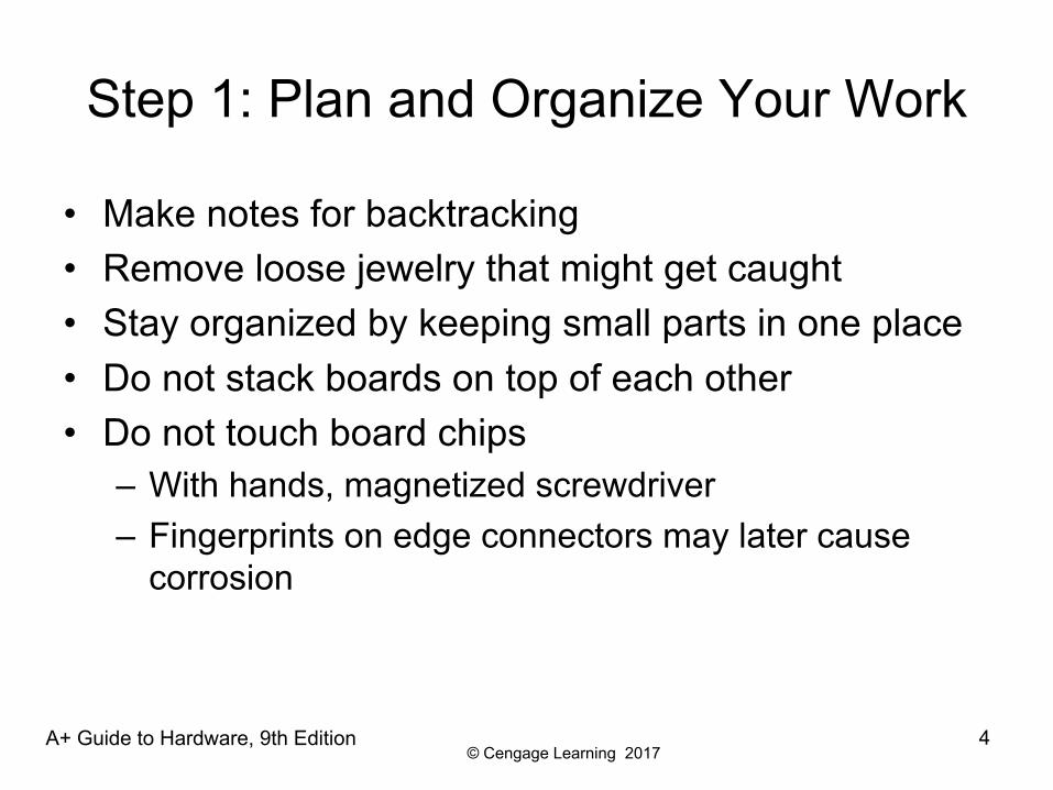
Step 1: Plan and Organize Your Work
• Make notes for backtracking• Remove loose jewelry that might get caught• Stay organized by keeping small parts in one place• Do not stack boards on top of each other• Do not touch board chips
– With hands, magnetized screwdriver– Fingerprints on edge connectors may later cause
corrosion
A+ Guide to Hardware, 9th Edition 4
© Cengage Learning 2017
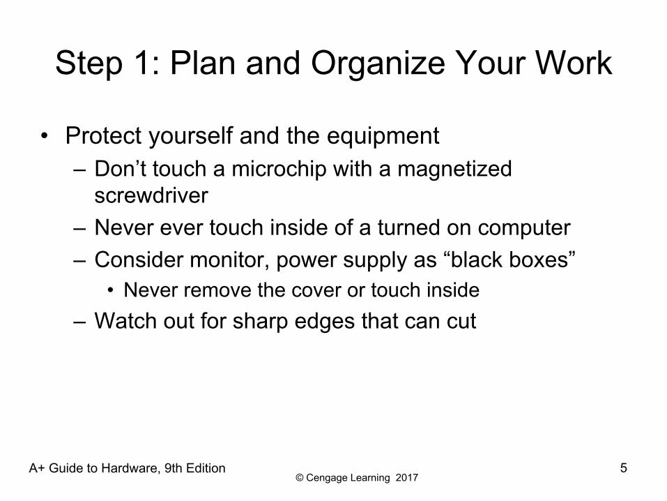
Step 1: Plan and Organize Your Work
• Protect yourself and the equipment– Don’t touch a microchip with a magnetized
screwdriver– Never ever touch inside of a turned on computer– Consider monitor, power supply as “black boxes”
• Never remove the cover or touch inside– Watch out for sharp edges that can cut
A+ Guide to Hardware, 9th Edition 5
© Cengage Learning 2017
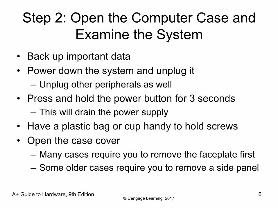
Step 2: Open the Computer Case and Examine the System
• Back up important data• Power down the system and unplug it
– Unplug other peripherals as well• Press and hold the power button for 3 seconds
– This will drain the power supply• Have a plastic bag or cup handy to hold screws• Open the case cover
– Many cases require you to remove the faceplate first– Some older cases require you to remove a side panel
A+ Guide to Hardware, 9th Edition 6
© Cengage Learning 2017
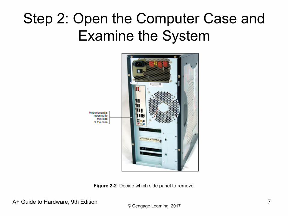
Step 2: Open the Computer Case and Examine the System
A+ Guide to Hardware, 9th Edition 7
Figure 2-2 Decide which side panel to remove
© Cengage Learning 2017
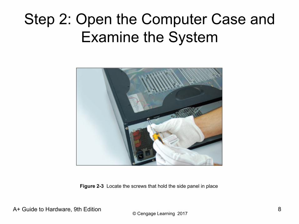
Step 2: Open the Computer Case and Examine the System
A+ Guide to Hardware, 9th Edition 8
Figure 2-3 Locate the screws that hold the side panel in place
© Cengage Learning 2017
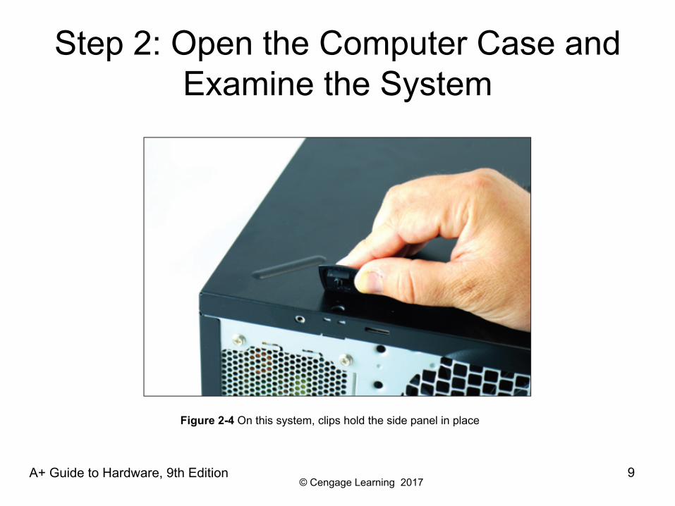
Step 2: Open the Computer Case and Examine the System
A+ Guide to Hardware, 9th Edition 9
Figure 2-4 On this system, clips hold the side panel in place
© Cengage Learning 2017
Step 2: Open the Computer Case and Examine the System
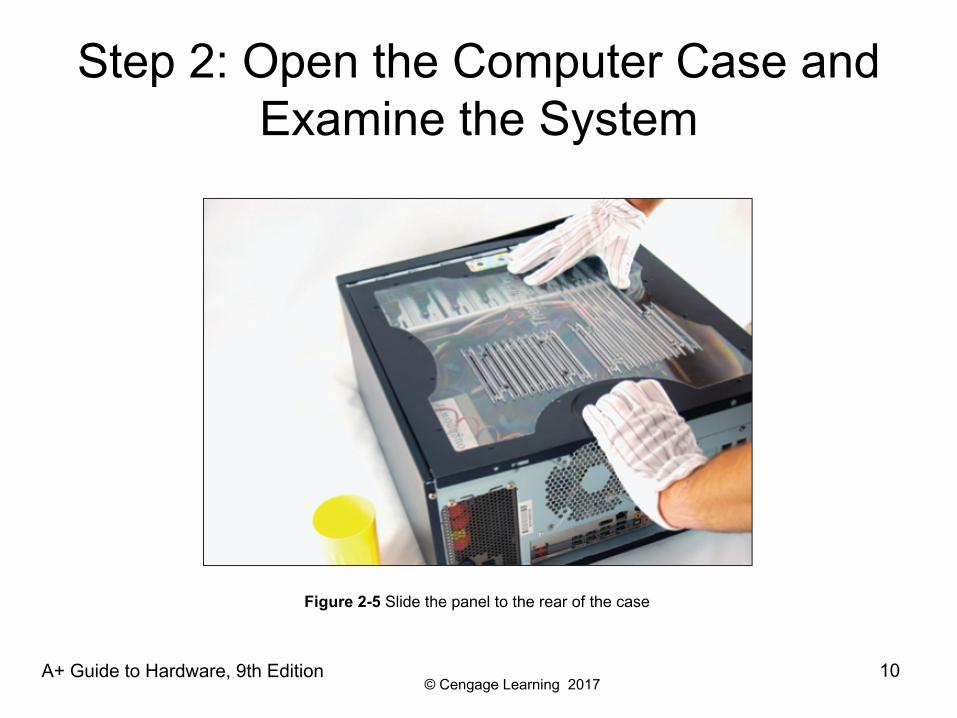
A+ Guide to Hardware, 9th Edition 10
Figure 2-5 Slide the panel to the rear of the case
© Cengage Learning 2017
Step 2: Open the Computer Case and Examine the System
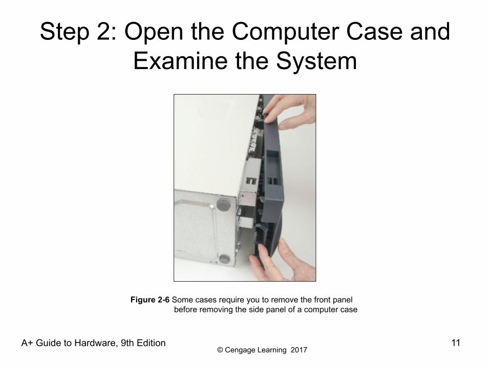
A+ Guide to Hardware, 9th Edition 11
Figure 2-6 Some cases require you to remove the front panel before removing the side panel of a computer case
© Cengage Learning 2017
Step 2: Open the Computer Case and Examine the System
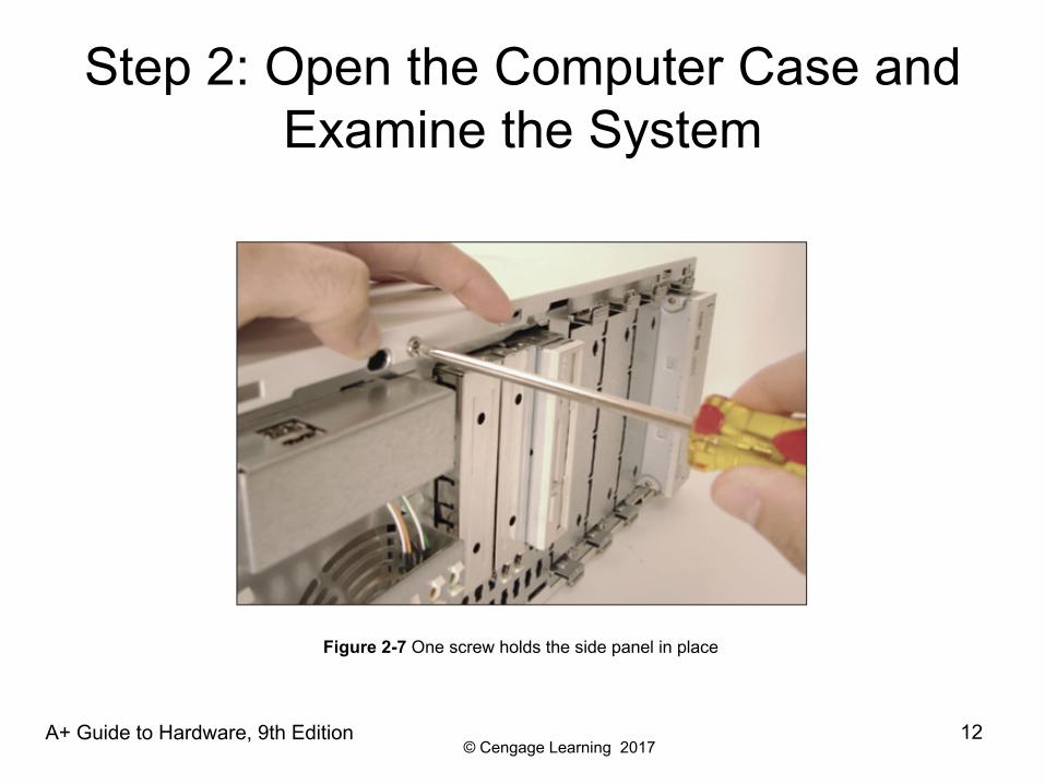
A+ Guide to Hardware, 9th Edition 12
Figure 2-7 One screw holds the side panel in place
© Cengage Learning 2017
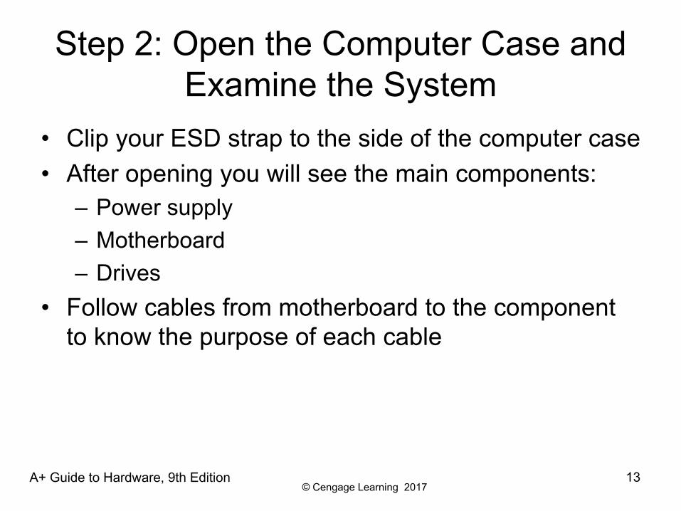
Step 2: Open the Computer Case and Examine the System
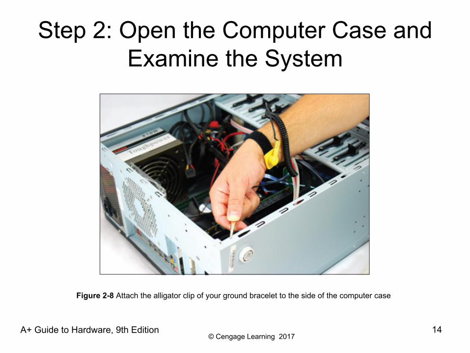
• Clip your ESD strap to the side of the computer case• After opening you will see the main components:
– Power supply– Motherboard– Drives
• Follow cables from motherboard to the component to know the purpose of each cable
A+ Guide to Hardware, 9th Edition 13
© Cengage Learning 2017
Step 2: Open the Computer Case and Examine the System
A+ Guide to Hardware, 9th Edition 14
Figure 2-8 Attach the alligator clip of your ground bracelet to the side of the computer case
© Cengage Learning 2017
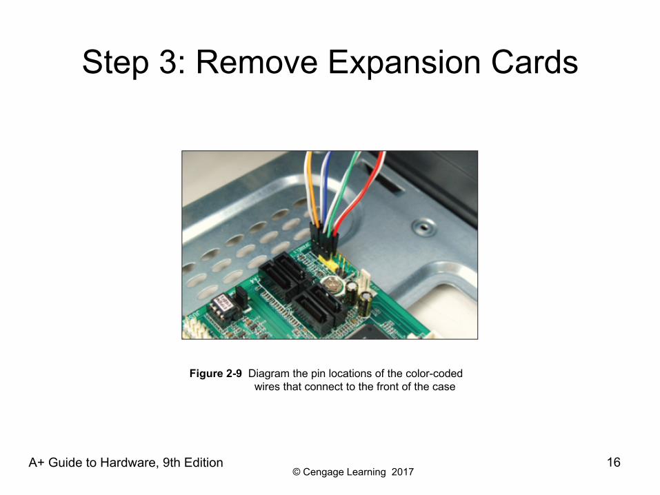
Step 3: Remove Expansion Cards
• If removing components:– Draw a diagram of all cable connections to the
motherboard, expansion cards, and drives– Use a felt-tip marker to mark components in order to
indicate a cable connection, board placement, orientation, etc…
A+ Guide to Hardware, 9th Edition 15
© Cengage Learning 2017
Step 3: Remove Expansion Cards
A+ Guide to Hardware, 9th Edition 16
Figure 2-9 Diagram the pin locations of the color-coded wires that connect to the front of the case
© Cengage Learning 2017
Step 3: Remove Expansion Cards
• To remove expansion cards:– Remove any wire or cable connected to the card– Remove the screw holding the card to the case– Grasp the card with both hands and remove it by
lifting straight up (can also rock the card from end to end)
– Don’t put your fingers on edge connectors or touch a chip
• It is best to store cards in an antistatic bag
A+ Guide to Hardware, 9th Edition 17
© Cengage Learning 2017
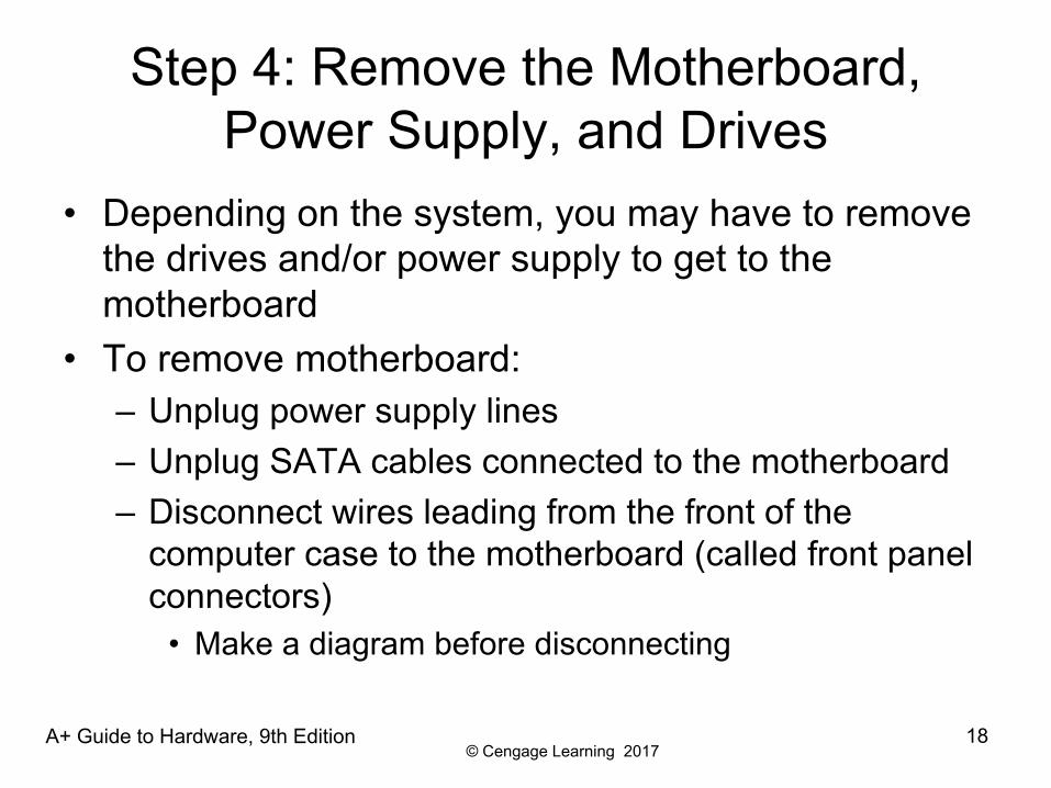
Step 4: Remove the Motherboard, Power Supply, and Drives
• Depending on the system, you may have to remove the drives and/or power supply to get to the motherboard
• To remove motherboard:– Unplug power supply lines– Unplug SATA cables connected to the motherboard– Disconnect wires leading from the front of the
computer case to the motherboard (called front panel connectors)
• Make a diagram before disconnecting
A+ Guide to Hardware, 9th Edition 18
© Cengage Learning 2017
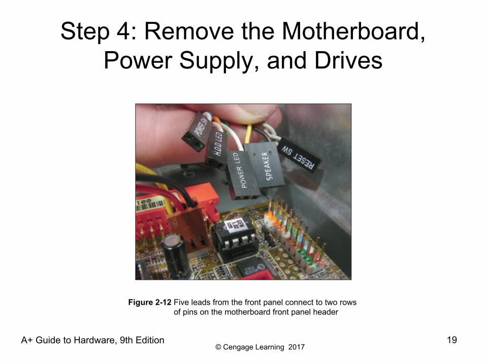
Step 4: Remove the Motherboard, Power Supply, and Drives
A+ Guide to Hardware, 9th Edition 19
Figure 2-12 Five leads from the front panel connect to two rowsof pins on the motherboard front panel header
© Cengage Learning 2017
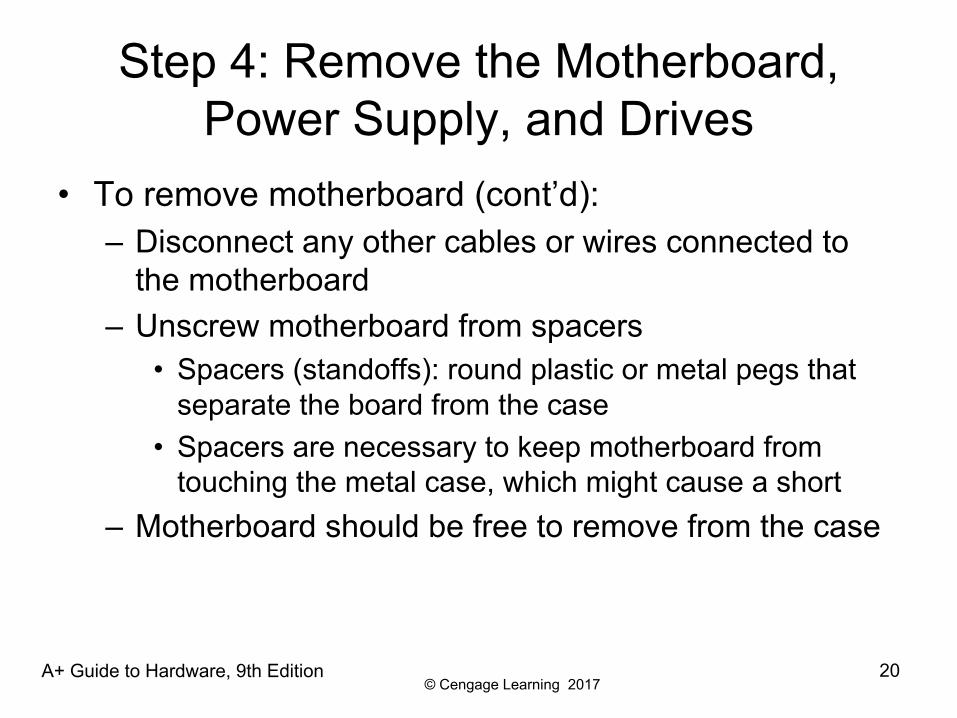
Step 4: Remove the Motherboard, Power Supply, and Drives
• To remove motherboard (cont’d):– Disconnect any other cables or wires connected to
the motherboard – Unscrew motherboard from spacers
• Spacers (standoffs): round plastic or metal pegs that separate the board from the case
• Spacers are necessary to keep motherboard from touching the metal case, which might cause a short
– Motherboard should be free to remove from the case
A+ Guide to Hardware, 9th Edition 20
© Cengage Learning 2017
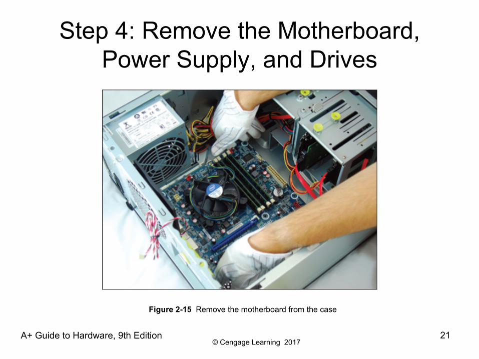
Step 4: Remove the Motherboard, Power Supply, and Drives
A+ Guide to Hardware, 9th Edition 21
Figure 2-15 Remove the motherboard from the case

© Cengage Learning 2017
Step 4: Remove the Motherboard, Power Supply, and Drives
• To remove the power supply from the case:– Look for screws that attach the power supply to the
computer case• Do not remove screws that hold power supply housing
together (do take housing apart)– Sometimes power supplies are also attached to the
case on the underside by recessed slots• Turn case over and look for slots• If present, determine in which direction you need to
slide the power supply to free it from the case
A+ Guide to Hardware, 9th Edition 22
© Cengage Learning 2017
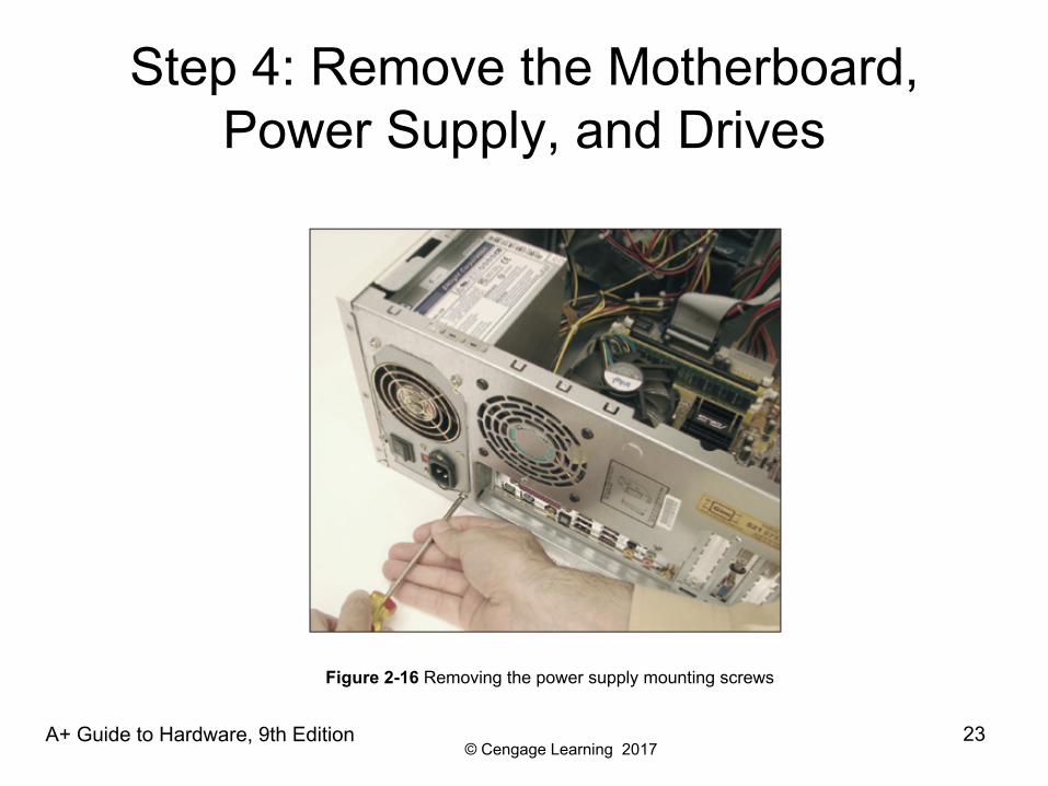
Step 4: Remove the Motherboard, Power Supply, and Drives
A+ Guide to Hardware, 9th Edition 23
Figure 2-16 Removing the power supply mounting screws
© Cengage Learning 2017
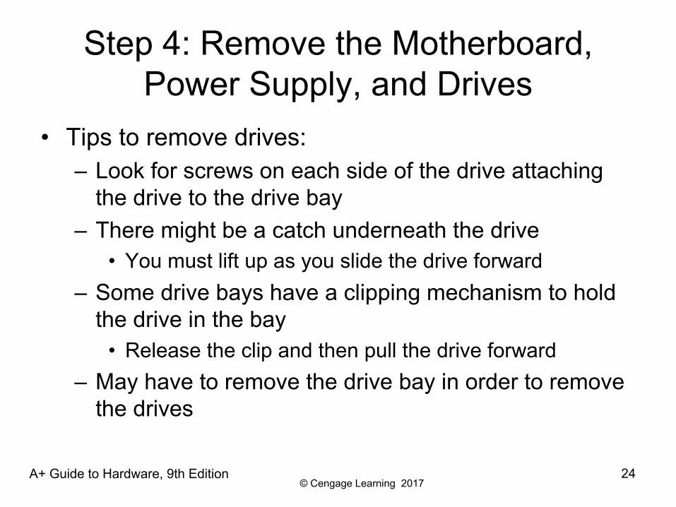
Step 4: Remove the Motherboard, Power Supply, and Drives
• Tips to remove drives:– Look for screws on each side of the drive attaching
the drive to the drive bay– There might be a catch underneath the drive
• You must lift up as you slide the drive forward– Some drive bays have a clipping mechanism to hold
the drive in the bay• Release the clip and then pull the drive forward
– May have to remove the drive bay in order to remove the drives
A+ Guide to Hardware, 9th Edition 24

© Cengage Learning 2017
Step 4: Remove the Motherboard, Power Supply, and Drives
A+ Guide to Hardware, 9th Edition 25
Figure 2-17 To remove this CD drive, first pull the clip forward torelease the drive from the bay
© Cengage Learning 2017
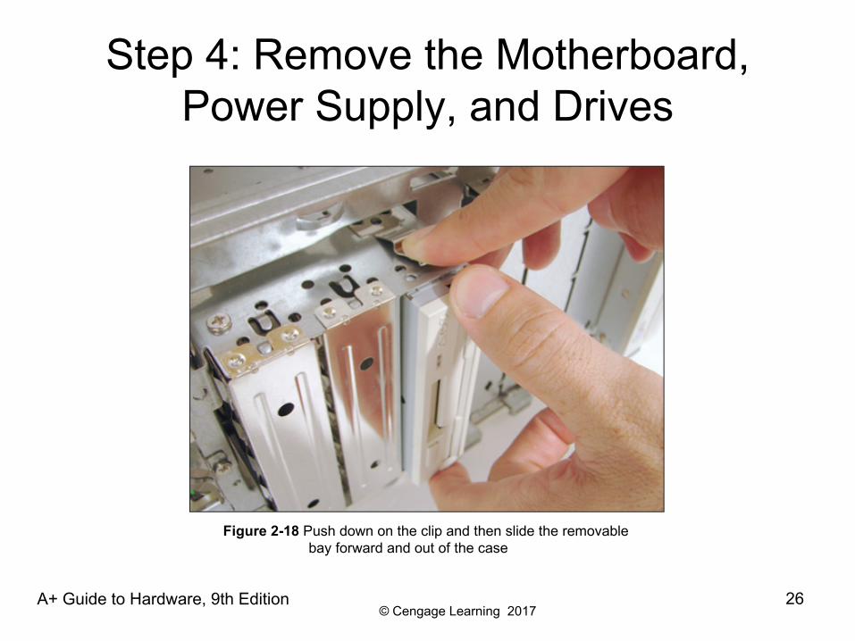
Step 4: Remove the Motherboard, Power Supply, and Drives
A+ Guide to Hardware, 9th Edition 26
Figure 2-18 Push down on the clip and then slide the removable bay forward and out of the case

© Cengage Learning 2017
Step 4: Remove the Motherboard, Power Supply, and Drives
A+ Guide to Hardware, 9th Edition 27
Figure 2-19 Drives in this removable bay are held in place with screws on each side of the bay
© Cengage Learning 2017
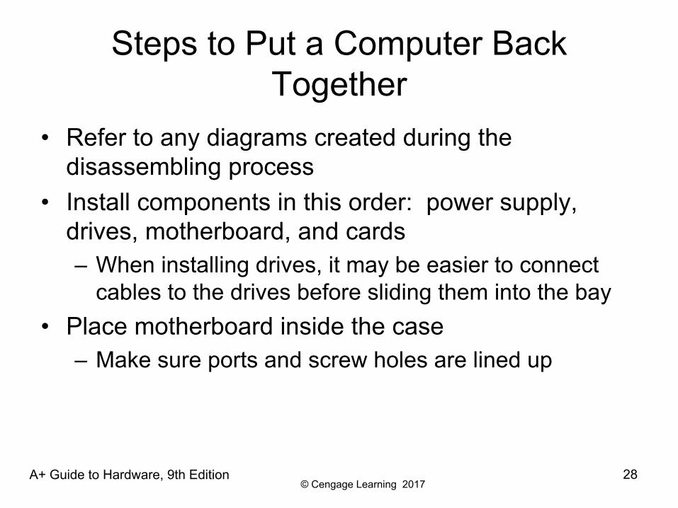
Steps to Put a Computer Back Together
• Refer to any diagrams created during the disassembling process
• Install components in this order: power supply, drives, motherboard, and cards– When installing drives, it may be easier to connect
cables to the drives before sliding them into the bay• Place motherboard inside the case
– Make sure ports and screw holes are lined up
A+ Guide to Hardware, 9th Edition 28
© Cengage Learning 2017
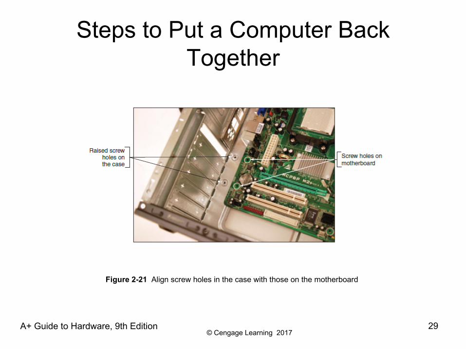
Steps to Put a Computer Back Together
A+ Guide to Hardware, 9th Edition 29
Figure 2-21 Align screw holes in the case with those on the motherboard
© Cengage Learning 2017
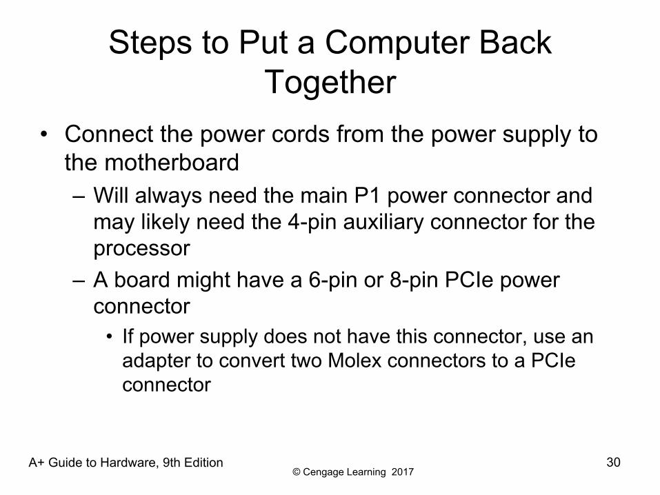
Steps to Put a Computer Back Together
• Connect the power cords from the power supply to the motherboard– Will always need the main P1 power connector and
may likely need the 4-pin auxiliary connector for the processor
– A board might have a 6-pin or 8-pin PCIe power connector
• If power supply does not have this connector, use an adapter to convert two Molex connectors to a PCIe connector
A+ Guide to Hardware, 9th Edition 30
© Cengage Learning 2017
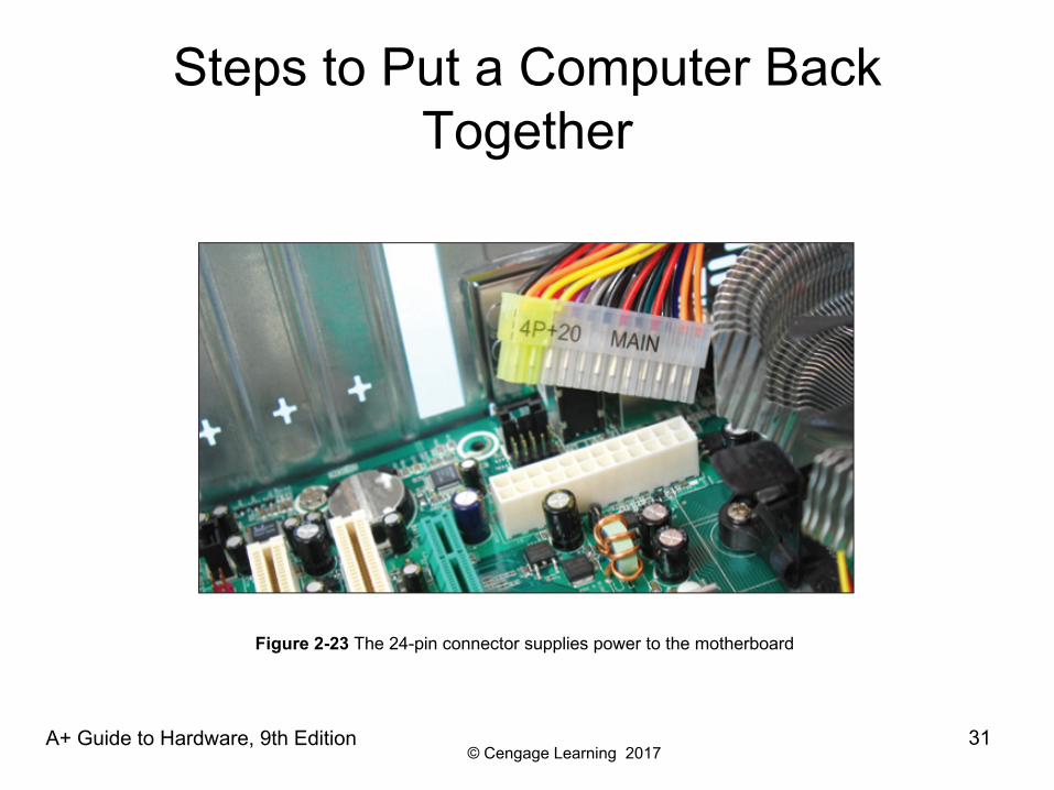
Steps to Put a Computer Back Together
A+ Guide to Hardware, 9th Edition 31
Figure 2-23 The 24-pin connector supplies power to the motherboard
© Cengage Learning 2017
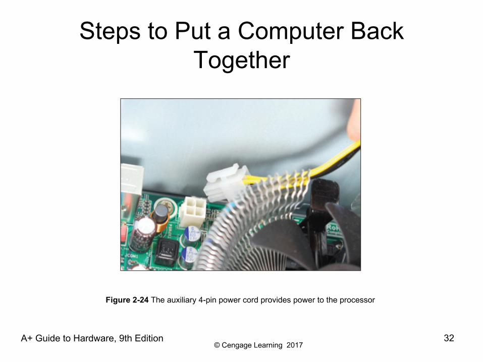
Steps to Put a Computer Back Together
A+ Guide to Hardware, 9th Edition 32
Figure 2-24 The auxiliary 4-pin power cord provides power to the processor
© Cengage Learning 2017
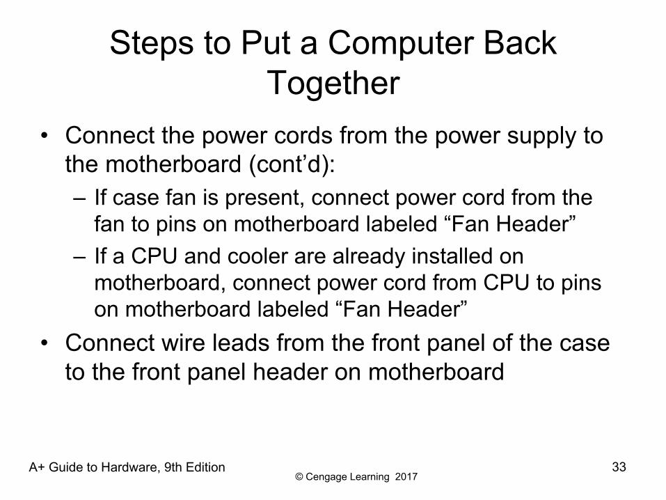
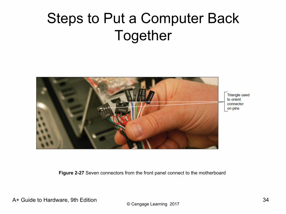
Steps to Put a Computer Back Together
• Connect the power cords from the power supply to the motherboard (cont’d):– If case fan is present, connect power cord from the
fan to pins on motherboard labeled “Fan Header”– If a CPU and cooler are already installed on
motherboard, connect power cord from CPU to pins on motherboard labeled “Fan Header”
• Connect wire leads from the front panel of the case to the front panel header on motherboard
A+ Guide to Hardware, 9th Edition 33
© Cengage Learning 2017
Steps to Put a Computer Back Together
A+ Guide to Hardware, 9th Edition 34
Figure 2-27 Seven connectors from the front panel connect to the motherboard
© Cengage Learning 2017
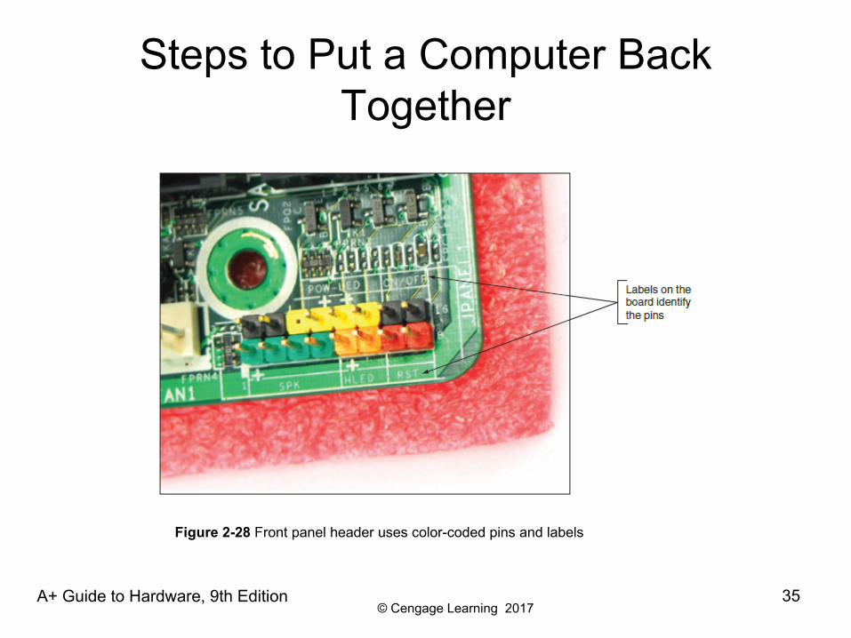
Steps to Put a Computer Back Together
A+ Guide to Hardware, 9th Edition 35
Figure 2-28 Front panel header uses color-coded pins and labels
© Cengage Learning 2017
Steps to Put a Computer Back Together
• Look for a small triangle embedded on the connector that marks one of the outside wires as pin 1– Line up pin 1 on connector with pin 1 marked on
motherboard – If labels on motherboard are not clear, consult user
guide for help
A+ Guide to Hardware, 9th Edition 36
© Cengage Learning 2017
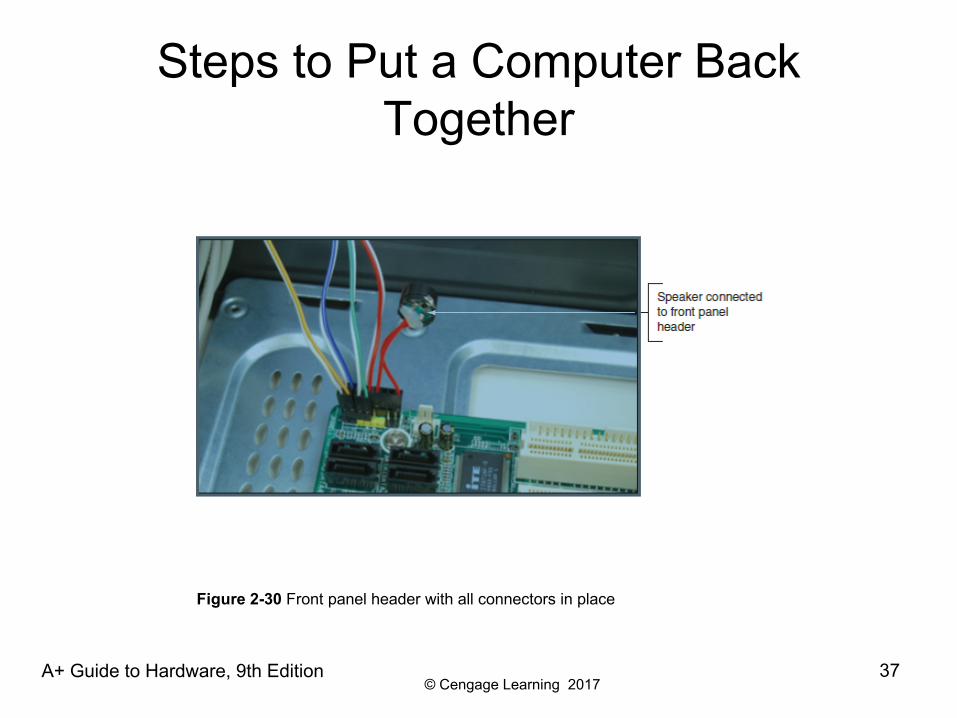
Steps to Put a Computer Back Together
A+ Guide to Hardware, 9th Edition 37
Figure 2-30 Front panel header with all connectors in place
© Cengage Learning 2017
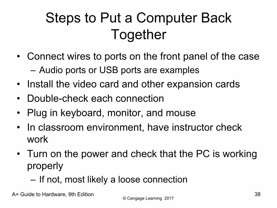
Steps to Put a Computer Back Together
• Connect wires to ports on the front panel of the case– Audio ports or USB ports are examples
• Install the video card and other expansion cards• Double-check each connection • Plug in keyboard, monitor, and mouse• In classroom environment, have instructor check
work• Turn on the power and check that the PC is working
properly– If not, most likely a loose connection
A+ Guide to Hardware, 9th Edition 38
© Cengage Learning 2017
Special Considerations when Supporting Laptops
• Laptops and their replacement parts cost more than desktop PCs
• Factors to consider that apply more to laptop than desktop computers:– Original equipment manufacturer’s warranty– Service manuals and diagnostic software provided by
the manufacturer– Customized installation of the OS unique to laptops– Advantage of order replacement parts directly from
the laptop manufacturer or authorized source
A+ Guide to Hardware, 9th Edition 39
© Cengage Learning 2017
Warranty Concerns
• Always check to see if laptop is under warranty before servicing
• Contacting technical support: information needed– Laptop model and serial number – Purchaser name, phone number, address
• Service options– On-site– Ship to authorized service center– Phone assistance or online chat
A+ Guide to Hardware, 9th Edition 40
© Cengage Learning 2017
Service Manuals and Other Sources of Information
• Service manuals save time– Enables safe laptop disassembly
• Locating documentation – Service manual– Manufacturer’s physical manual– Manufacturer’s Web site
• Support or FAQ pages– Third party websites
• User manual– Provides basic maintenance tasks
A+ Guide to Hardware, 9th Edition 41
© Cengage Learning 2017
Diagnostic Tools Provided by Manufacturers
• To determine problem components use diagnostic software provided by manufacturer– Sources:
• Manufacturer’s Web site• CDs bundled with the notebook• Hard drive or floppy disk
– Example: PC-Doctor• Included with Lenovo, Fujitsu, and HP notebooks• Can be purchased separately
A+ Guide to Hardware, 9th Edition 42
© Cengage Learning 2017
How to Work Inside a Laptop Computer
• It may become necessary to open a laptop case to upgrade memory, exchange a hard drive, or replace a failed component
• Replacing a broken LCD panel or motherboard can be a complex process
• Screws and nuts on a laptop are smaller than a desktop– Require smaller tools
A+ Guide to Hardware, 9th Edition 43
© Cengage Learning 2017
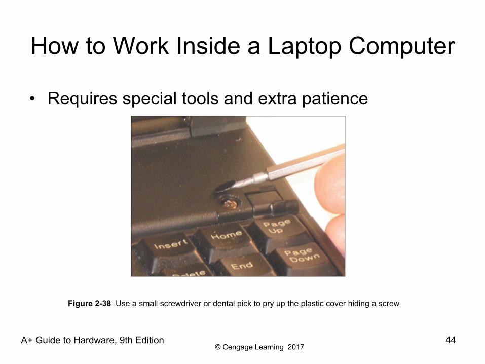
How to Work Inside a Laptop Computer
• Requires special tools and extra patience
A+ Guide to Hardware, 9th Edition 44
Figure 2-38 Use a small screwdriver or dental pick to pry up the plastic cover hiding a screw
© Cengage Learning 2017
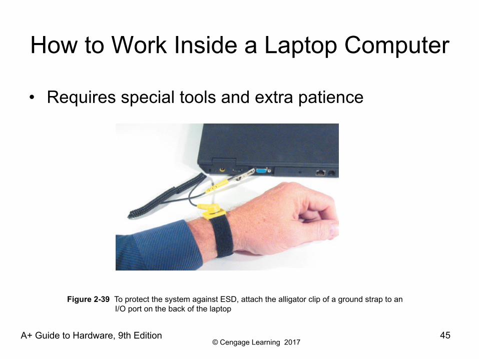
How to Work Inside a Laptop Computer
• Requires special tools and extra patience
A+ Guide to Hardware, 9th Edition 45
Figure 2-39 To protect the system against ESD, attach the alligator clip of a ground strap to an I/O port on the back of the laptop
© Cengage Learning 2017
How to Work Inside a Laptop Computer
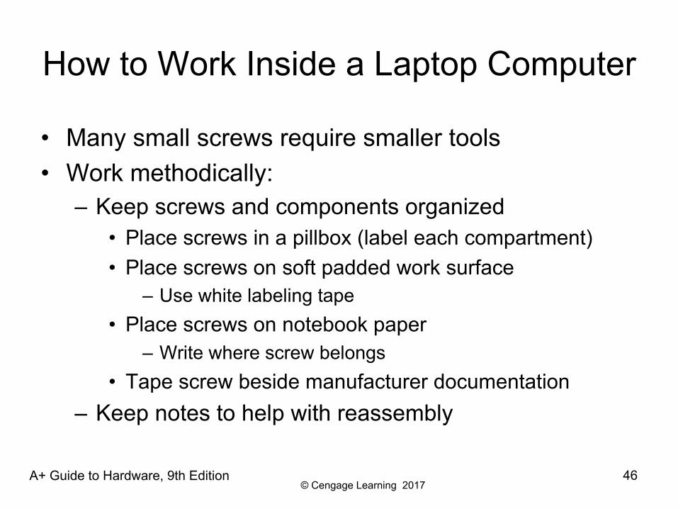
• Many small screws require smaller tools• Work methodically:
– Keep screws and components organized• Place screws in a pillbox (label each compartment)• Place screws on soft padded work surface
– Use white labeling tape• Place screws on notebook paper
– Write where screw belongs• Tape screw beside manufacturer documentation
– Keep notes to help with reassembly
A+ Guide to Hardware, 9th Edition 46
© Cengage Learning 2017
How to Work Inside a Laptop Computer
A+ Guide to Hardware, 9th Edition 47
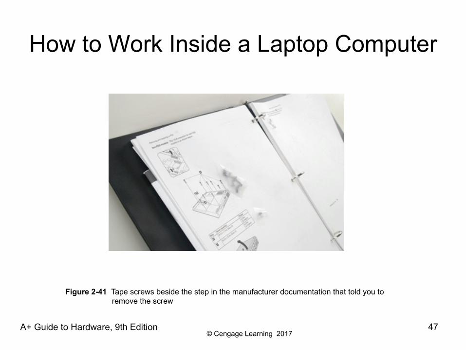
Figure 2-41 Tape screws beside the step in the manufacturer documentation that told you to remove the screw
© Cengage Learning 2017
How to Work Inside a Laptop Computer
• Disassembly tips:– Find the hardware service manual– Consider the warranty might still apply
• Opening the case might void the warranty– Take the time necessary, do not force anything– Protect against ESD– Understand ZIF connectors– Pry up plastic covers with dental pick or screwdriver– Plastic screws may be used only once– Disassemble components in order
A+ Guide to Hardware, 9th Edition 48
© Cengage Learning 2017
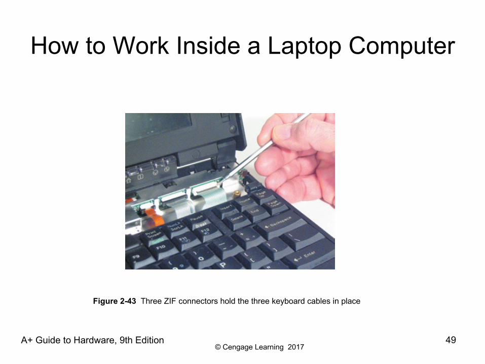
How to Work Inside a Laptop Computer
A+ Guide to Hardware, 9th Edition 49
Figure 2-43 Three ZIF connectors hold the three keyboard cables in place
© Cengage Learning 2017
How to Work Inside a Laptop Computer
• Reassembly tips:– Reassemble notebook in reverse order– Tighten, but do not over tighten, all screws– Before installing the battery or AC adapter verify there
are no loose parts inside the notebook
A+ Guide to Hardware, 9th Edition 50
© Cengage Learning 2017
Summary
• When working inside a computer, stay organized, keep careful notes, and follow all safety procedures
• Before opening a case, shut down the system, unplug it, disconnect all cables, and press the power button to drain residual power
• An expansion card fits in a slot on the motherboard and is anchored to the case by a single screw or clip
• Laptop computers are designed for travel, so smaller and more durable replacement parts cost more than they do for desktops
A+ Guide to Hardware, 9th Edition 51
© Cengage Learning 2017
Summary
• The laptop manufacturer documentation are useful when disassembling, troubleshooting, and repairing a notebook
• When an internal component needs replacing, consider the possibility of disabling the component and using an external peripheral device in its place
• Replacing the laptop might be more cost effective than performing labor-intensive repairs
• When disassembling a laptop, the manufacturer’s service manual is essential
A+ Guide to Hardware, 9th Edition 52
© Cengage Learning 2017
Summary
• When upgrading components on a laptop, use components that are the same brand as the laptop
• Follow directions in a service manual to disassemble a laptop
A+ Guide to Hardware, 9th Edition 53