a home agent initiated handover solution for fine-grained...
TRANSCRIPT
A Home Agent Initiated Handover Solution
for Fine-grained Offloading in Future
Mobile Internet Architectures: Survey and
Experimental Evaluation
László Bokor†, József Kovács‡, Csaba Attila Szabó †
†Inter-University Centre for Telecommunications and Informatics (ETIK),
Kassai u. 26. H-4028, Debrecen, Hungary, and
Dept. of Networked Systems and Services, Budapest University of Technology and Economics,
{bokorl | szabo}@hit.bme.hu
‡Computer and Automation Research Institute, Hungarian Academy of Sciences (MTA),
Kende u. 13-17, H-1111, Budapest, Hungary
ABSTRACT
The currently standardized IP Flow Mobility (IFOM) solution in 3GPP is strictly User
Equipment (UE) centric as the operator must firstly deliver the flow routing policies to the
UE, and then the UE must provide these policies to the Packet Data Network Gateway
(PGW). Network-based (NB) solutions try to eliminate the above limitations and create an
operator centric flow management framework. This paper is committed to give an overview
of existing offloading techniques, to introduce the power of network-based solutions, and to
propose a MIPv6/DSMIPv6 based NB-IFOM scheme relying on Home Agent initiated flow
binding and aiming to enable operators to enforce IP flow routing policies without involving
the UE first, such making able the PCRF (Policy and Charging Rules Function) to decide on
the flow routing policy based on e.g., the available resources in the network, before signaling
the policies to the UE. We have implemented our proposal, and performed an extensive
evaluation in a hybrid real-emulated testbed environment.
Keywords: offloading, traffic management, 3GPP/non-3GPP access, IFOM, NB-IFOM,
Direct Tunnel, LIPA, SIPTO, MIPv6, DSMIPv6, Home Agent initiated handovers, flow
bindings
INTRODUCTION
The enormous growth of mobile data traffic has surprised mobile operators and vendors by
choking existing communication networks a lot earlier than expected: bottlenecks of anchor
nodes, sub-optimal routes and hierarchical/centralized architectures became hot research and
development topics. As a result of the progressive innovation, novel technologies have
emerged quickly to manage routing optimization of data flows, divert user packets around
network bottlenecks and critical entities of the architecture, and to redirect traffic directly
to/from the Internet. All the techniques around this problem space are called data offloading
and used for any kind of complementary network technologies for optimized delivery of data
originally targeted for cellular networks. The set of rules aiming at triggering the offloading
action can either be set by the mobile operator or the mobile subscriber and the code operating
on the rules can run in the user terminal, in a core network entity or can be divided between
different elements of the architecture. For the end users the gain of applying offloading
schemes relies on extended data service cost control and the availability of higher bandwidth.
From the operators’ perspective the main purpose for introducing offloading in the network is
to avoid congestion of the cellular architecture due to mobile data traffic evolution. Key
technologies include pico- and femtocells, Wi-Fi, Content Delivery Networks (CDNs),
routing and media optimization, Traffic Engineered Handover (TEHO), and Core Network
Offloading as the most important schemes to reduce the congestion and load on the operator’s
network.
TEHO techniques focus on decision mechanisms to be involved in radio access changes with
a goal not restricted to cope with degradation of signal conditions but also to cover the
improvement of traffic conditions in the IP Connectivity Access Network (IP-CAN) together
with the improvement and maintenance of the user QoS/QoE. The two main offloading
techniques which support TEHO in reaching the above goals are the IP Flow Mobility
(IFOM) (3GPP TS 23.261, September 2010), (3GPP TR 23.829, Sept. 2010) and Multi-
Access PDN Connectivity (MAPCON) (3GPP TR 23.861, February 2010). MAPCON refers
to the technique of simultaneously using two or more APNs (Access Point Names) which
enables use cases such as using LTE/LTE-A for QoS demanding applications and Wi-Fi for
best effort traffic. IFOM refers to the technique of using the same APN across two or more
wireless access networks (e.g., LTE/LTE-A and Wi-Fi) and aims to enable seamless roaming
of applications across different radio access technologies. Currently the key tool to handle IP
handoffs between 3GPP and non-3GPP technologies is the IEEE 802.21 Media Independent
Handover (MIH) standard (IEEE, Jan. 2009) which provides information and handover
assistance services for heterogeneous mobility scenarios. Another tool is the Access Network
Discovery and Selection Function (ANDSF) specified in (3GPP TS 23.261, September 2010),
(3GPP TS 23.402, June, 2011) for EPS. The ANDSF transfers the mobile network operator
policy rules to connect through non-3GPP access technologies to the UE and thus enables an
advanced traffic steering that adapts to the QoS/QoE and the actual traffic conditions of the
controlled 3GPP network.
The currently standardized IFOM solution in 3GPP is strictly UE centric as the operator must
first deliver the flow routing policies to the UE, and then the UE must provide these policies
to the PDN Gateway. Also the ANDSF has no interface to the Policy and Charging Control
(PCC) system, therefore requires other ways to get informed about the updated flow routing
policy for a particular UE.
In this paper we study an NB-IFOM (Network-based IP Flow Mobility) solution built upon
Mobile IPv6 (Perkins, Johnson, & Arkko, 2011) in order to eliminate the above limitations
and create an operator centric flow management framework. The advantages of NB-IFOM
enable operators to enforce IP flow routing policies without involving the UE first, thus
making able the PCRF (Policy and Charging Rules Function, the central policy control entity
of 3GPP architectures) to decide on the flow routing policy based on e.g., the available
resources in the network, before signaling the policies to the UE. The network-based solution
is more efficient than the ones that rely on the UE to perform policy acquisition and
enforcement: in the current, UE centric standard it is possible that the network context and
resource availability may have changed by the time the UE provides the routing policies to
the network; therefore the PCRF will not be able to authorize the new flow policies anymore.
Such situations can be avoided if NB-IFOM is applied in the architecture.
The rest of this paper is organized as follows. The next section gives a general overview of
the offloading paradigm together with the detailed introduction of the most promising
offloading techniques like Direct Tunnel, LIPA, SIPTO, IFOM. This is followed by the
discussion of network based IP flow mobility. Within these two sections we try to give a
complete survey of existing offloading solutions, but the focus will be on the IP level
solutions. We continue with the introduction of NB-IFOM proposal and implementation
details of our scheme which is followed by the introduction of our evaluation scenarios,
hybrid measurement setups and the analysis of the collected results. At the end of the paper
we present a discussion, draw our concluding remarks and discuss the planned future work.
BACKGROUND
This section explores the main drivers and demands for the most promising mobile data
offloading techniques, including a presentation of state-of-the-art schemes. The focus of this
section is on 3G and beyond 3G systems; therefore it closely studies the technologies
available to enhance, augment and extend existing networks. The main evolutionary steps
leading to new operator oriented solutions and offloading strategies are highlighted, and
detailed introduction of Direct Tunneling (DT), Selective IP Traffic Offload (SIPTO), Local
IP Access (LIPA) and IP Flow Mobility (IFOM) are provided to illustrate the potential and
power of mobile data offloading in advanced traffic engineering in future mobile internet
architectures.
Introduction to the evolution of cellular mobile internet architectures
In Phase 1 (1995) the main entities of the GSM architecture have been introduced. Base
Stations and Base Station Controllers form hierarchy to handle radio access tasks. The core
network includes the Home and Visitor Location Registers that provide information about the
subscriber and the current location (VLR area) of the mobile station, and the mobile switching
centre (MSC), which constitutes the interface between the radio system and the fixed
networks, and performs switching and call handling. In Phase 2 (1996) additional entities
have been introduced like the Authentication Center, Equipment Identity Register, Gateway
MSC, Interworking Function between the Public Land Mobile Network and fixed networks
(ISDN, PSTN, PDNs). The reason behind the hierarchization and centralization of the GSM
architecture was both technical and economical. Primarily it offloaded the switching
equipment (cross-bar switch or MSC). In parallel, existing ISDN switches could be re-used as
MSCs only if special voice encoding entities were introduced below the MSCs, hence further
strengthening the hierarchical structure of the network.
The introduction of packet switching did not change the essential structure of the network at
all. The main driver to introduce packet switching was that it allowed multiplexing hence
resources could be utilized in a greater extent. Circuit switching does not share an allocated
virtual circuit with other transmissions. In Phase 2+ (1997) the packet-switched (PS) domain
were defined, hence General Packet Radio Service (GPRS) support nodes are added to the
network. In the PS domain the Serving GPRS Support Node (SGSN) stores subscription and
location information to each subscriber registered to it. The Gateway GPRS Support Node
(GGSN) stores subscription and routing information needed to tunnel data from the Packet
Data Network (PDN) to the MS for subscribers with active packet data protocol (PDP; e.g.,
IP, X.25, Frame Relay) context on the GPRS Support Nodes. This architecture guarantees
with interfaces the transit between CS and PS domains.
Release 1999 (2002) describes the well known UMTS architecture clearly separating the CS
and PS domains. Seeing that UMTS was designed to be the successor of GSM, it is not
surprising that the central anchors remained in place in 3G and beyond. Progress of mobile
and wireless communication systems introduced some fundamental changes. The most drastic
among them was that IP has become the unique access protocol for data networks and the
continuously increasing future wireless traffic is also based on packet data (i.e., Internet
communication). Due to the collateral effects of this change a convergence procedure started
to introduce IP-based transport technology in the core and backhaul network.
In Release 4 (2003) the Media gateway function is specified for the CS domain to support
media conversion, voice coding, payload processing and to translate between CS bearers, PS
media streams. It is the premonitory sign of the introduction of the IMS core network
functions in Release 5 (2003) for provision of IP services delivered over the PS domain. IMS
provides a common service layer for IP-based multimedia services, and aids the fixed-mobile
convergence.
Release 6 (2005) mainly introduces WLAN interworking and Multimedia Broadcast Multicast
Service related entities for point-to-multipoint communication in the 3GPP architecture. Note
that the latter scheme can be considered unsuccessful due to lack of practical deployment.
The enormous increase of IP-based data traffic offloading and flattening of hierarchical and
centralized functions became the main driving forces in the further evolution of 3GPP
network architectures.
Release 7 (also called Internet HSPA, 2008) supports the integration of the RNC (Radio
Network Controller) with the NodeB providing a one node based radio access network. This
architectural change was necessary to avoid performance bottlenecks caused by RNCs facing
increasing IP traffic demands. Particularly the highly increasing smart phone generated traffic
and Machine-to-Machine (M2M) demands represent challenges to network RNCs and
SGSNs, because they generate high volume of tiny packets which highly utilize the central
servers.
Another architectural enhancement of this release is the elaboration of Direct Tunnel service
(3GPP TS 23.060, June 2011) which can be considered as the first mobile data offloading
technique standardized in 3GPP by allowing user traffic offload from SGSN. This mechanism
tries to reduce the number of user-plane traffic anchors, however it also adds complexity in
charging inter-PS traffic because SGSNs cannot account the traffic passing in direct tunnels.
The Direct Tunnel service is further detailed in the next section.
Release 7 also specifies the PCRF function which integrates QoS policy control and charging
that were previously two separated functions. This makes possible more granular, IP flow-
based charging and QoS enforcement for session-based applications in the PS domain,
independently from the IP connectivity access network between the UE and the IMS entities.
Release 8 (2010) introduces a new PS domain, i.e., the Evolved Packet Core (EPC).
Compared to four main GPRS PS domain entities of Release 6, i.e. the base station (called
NodeB), RNC, SGSN, GGSN, this architecture has one integrated radio access node (called
eNodeB) containing the precious base station and the radio network control functions, and
three main functional entities in the core, i.e. the Mobility Management Entity (MME), the
Serving GW (S-GW) and the Packet data Network GW (PDN GW).
The MME is the control plane entity supporting Non Access Stratum (NAS) signaling and
security, inter core network node signaling for mobility between 3GPP access networks, PDN
GW and Serving GW selection, SGSN selection for handovers to 2G or 3G 3GPP access
networks, roaming, bearer management including dedicated bearer establishment, lawful
interception of signaling, support for handovers to 3GPP2 access networks. The Serving GW
is the user plane interface towards Evolved UTRAN. It is the local mobility anchor for inter-
eNodeB and inter-3GPP handover. It provides lawful packet interception, accounting, and
event reporting to PCRF. The PDN GW is the gateway towards the PDN. Its functions
include per-user based packet filtering with deep packet inspection, lawful interception, UE IP
address allocation, mobility management, DHCPv4 and v6 functions for configuration,
transport level packet marking, uplink and downlink service level charging and rate
enforcement.
Release 9 (2010) introduces the definition of Home (e)NodeB Subsystem. These systems
allow unmanaged deployment of femtocells at indoor sites, providing almost perfect
broadband radio coverage in residential and working areas, and offloading the managed, pre-
panned macro-cell network. Femtocells represent many technical challenges which include
resource allocation, timing/synchronization, backhaul capacity with appropriate QoS,
interference management with macrocells and femtocells, handoffs, mobility, emergency
service provision facing that users may switch off HNodeBs, open or restricted access to a
group of subscribers or the combination of both, and securely bridging the femtocell with the
core network. Low-power base stations can eliminate coverage holes in the macro-only
system; however these systems require smarter radio resource coordination and interference
management among base stations.
In Release 10 (2010) Selective IP Traffic Offload (SIPTO), Local IP Access (LIPA) and IP
Flow Mobility (IFOM) services have been published (3GPP TS 23.401 V10.4.0, June 2011)
(3GPP TR 23.829, Sept. 2010). These enable local breakout of certain IP traffic from the
macro-cellular network or from the H(e)NodeB subsystems, in order to offload the network
elements in the PS and EPC PS domain. Details are presented in the next section.
Promising offloading techniques
This section provides more detailed introduction of the most promising offloading techniques
available in the literature.
Direct Tunnel
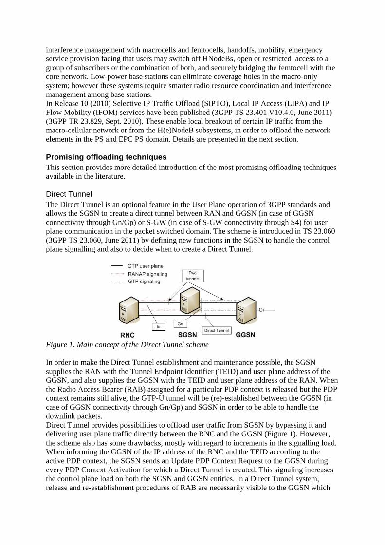
The Direct Tunnel is an optional feature in the User Plane operation of 3GPP standards and
allows the SGSN to create a direct tunnel between RAN and GGSN (in case of GGSN
connectivity through Gn/Gp) or S-GW (in case of S-GW connectivity through S4) for user
plane communication in the packet switched domain. The scheme is introduced in TS 23.060
(3GPP TS 23.060, June 2011) by defining new functions in the SGSN to handle the control
plane signalling and also to decide when to create a Direct Tunnel.
Figure 1. Main concept of the Direct Tunnel scheme
In order to make the Direct Tunnel establishment and maintenance possible, the SGSN
supplies the RAN with the Tunnel Endpoint Identifier (TEID) and user plane address of the
GGSN, and also supplies the GGSN with the TEID and user plane address of the RAN. When
the Radio Access Bearer (RAB) assigned for a particular PDP context is released but the PDP
context remains still alive, the GTP-U tunnel will be (re)-established between the GGSN (in
case of GGSN connectivity through Gn/Gp) and SGSN in order to be able to handle the
downlink packets.
Direct Tunnel provides possibilities to offload user traffic from SGSN by bypassing it and
delivering user plane traffic directly between the RNC and the GGSN (Figure 1). However,
the scheme also has some drawbacks, mostly with regard to increments in the signalling load.
When informing the GGSN of the IP address of the RNC and the TEID according to the
active PDP context, the SGSN sends an Update PDP Context Request to the GGSN during
every PDP Context Activation for which a Direct Tunnel is created. This signaling increases
the control plane load on both the SGSN and GGSN entities. In a Direct Tunnel system,
release and re-establishment procedures of RAB are necessarily visible to the GGSN which
also increases the volume of control plane messages between the SGSN and GGSN. In cases
when the radio-link quality is low, the frequent RAB release and re-establishment will result
also in increased signaling load on the GSN nodes. Also there are some Intra-SGSN
procedures (e.g., intra-SGSN inter-RNC procedures), which are not visible for the GGSN in a
legacy (i.e., two-tunnel) system. These procedures will become visible to the GGSN when
applying Direct Tunnel and such will further increase the volume of signaling messages on
the GSN entities.
If the system operates an active Direct Tunnel, the SGSN will not be able to measure data
traffic volumes belonging to the PDP context for which the particular Direct Tunnel is
created. It means that activating a Direct Tunnel for a PDP context will result in inconsistency
in the data traffic volumes measured by the SGSN and GGSN for that particular PDP context.
Therefore, if a Direct Tunnel is active, traffic volume based charging in the packet switched
domain cannot be operated only based on SGSN charging information. Direct Tunnel also
limits the operation of the system’s Lawful Interception (LI) capabilities: when Direct Tunnel
is applied, LI can only gather reliable user plane communication information from the GGSN.
However, when some LI functions in the GGSN are employed, certain control plane
information (e.g., SMS and mobility management related information) can only be gathered
from the SGSN entity.
Local IP Access (LIPA) and Selected IP Traffic Offload (SIPTO)
Traffic offloading schemes and particularly LIPA/SIPTO were analyzed and started to be
standardized within the 3GPP SA2 working group. LIPA is designed for residential and/or
corporate environments in order to provide local network access as introduced in (3GPP TR
23.829, Sept. 2010), (3GPP TS 22.220, June, 2011). LIPA enables an IP capable UE
connected via Home(e)NodeB to access other IP capable entities in the same
residential/enterprise IP network without the user plane traversing the core network entities.
LIPA is established by the UE requesting a new PDN connection to an APN for which LIPA
is enabled, and the network selecting the Local GW associated with the H(e)NodeB, and
enabling direct user path between the Local GW and the H(e)NodeB. Mobility of LIPA PDN
connections is still not supported in Release 10. SIPTO (3GPP TR 23.829, Sept. 2010),
(3GPP TS 22.220, June, 2011) enables per APN and/or per IP flow class based traffic offload
towards a defined IP network close to the UE's point of attachment to the access network. In
order to avoid SGSN/S-GW from the path, Direct Tunnel mode should be used. The main
objective of these 3GPP efforts is to identify potential architectural enhancements and
functionalities in order to support LIPA for the H(e)NB subsystem and SIPTO for the H(e)NB
subsystem as well as for the macro-cellular network.
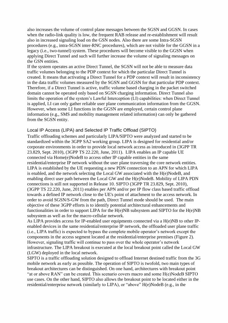
As LIPA provides access for IP-enabled user equipments connected via a H(e)NB to other IP-
enabled devices in the same residential/enterprise IP network, the offloaded user plane traffic
(i.e., LIPA traffic) is expected to bypass the complete mobile operator’s network except the
components in the access segment located at the residential/enterprise premises (Figure 2).
However, signaling traffic will continue to pass over the whole operator’s network
infrastructure. The LIPA breakout is executed at the local breakout point called the Local GW
(LGW) deployed in the local network.
SIPTO is a traffic offloading solution designed to offload Internet destined traffic from the 3G
mobile network as early as possible. The operation of SIPTO is twofold, two main types of
breakout architectures can be distinguished. On one hand, architectures with breakout point
“at or above RAN” can be created. This scenario covers macro and some H(e)NodeB SIPTO
use cases. On the other hand, SIPTO also allows the breakout point to be located either in the
residential/enterprise network (similarly to LIPA), or “above” H(e)NodeB (e.g., in the
backhaul segment or in the H(e)NodeB-GW entity). This scenario mainly covers LIPA and
some H(e)NodeB SIPTO use cases.
In the most common scenario, the traffic offloading takes place on the data path between the
UTRAN/LTE and the SGSN/SGW (Figure 2). The scheme allows the traffic offloading
functions to transparently monitor the Radio Access Network Application Part (RANAP)
control traffic and based on this information it becomes possible to detect and steer Internet
destined communication sessions. Detection and intervention can be performed based e.g., on
the used APN or on the IMEI, as several Internet-only devices, as HSPA-enabled laptops are
identifiable in this way. E.g., (3GPP TR 23.829, Sept. 2010) proposes a new SIPTO-enabled
flag associated with each APN in the user’s subscription indicating whether the connection to
that APN is enabled/disabled for SIPTO. The same scheme is followed in the case of LIPA.
When the scheme detects sessions bound to inside operator services, the traffic offloading will
not take any action and user data traffic will travel the standard path, without the shortcut of
the traffic offloading function. In the case of sessions bound to the Internet, SIPTO functions
alter the traffic path in order to bypass both the SGSN (SGW) and GGSN (PGW) and
forwarding it directly to the nearest Internet peering point. The main control plane functions
(e.g., location updates to HLR) remain in the SGSN/GGSN or SGW/PGW entities and will
not be affected by SIPTO. Applying fine-grained traffic selection policy schemes, SIPTO can
identify and direct specific Internet destined user traffic to the operator’s CDN or other locally
deployed service in case of need.
Figure 2: LIPA (left) and SIPTO (right) deployment scenarios
Similarly to LIPA, SIPTO schemes also require a local breakout point. The entity is called
LGW (Local Gateway), which should either be collocated with the H(e)NB or form a
standalone element connected directly to the H(e)NB subsystem. SIPTO offloading for macro
cellular network takes place at or above the RAN. By performing offloading for selected IP
traffic closer to the users (i.e., when the breakout point is located close to the edge of the
network), operators could significantly reduce the load on their network resources such PDN
and/or Serving gateways. Also suboptimal routing in the mobile backhaul segment may be
eliminated.
The connection with the operator’s core network is achieved through the IP backhaul by
spanning a secure tunnel between the H(e)NB and a Security Gateway (SeGW) in the core
(Figure 2). IP traffic from the local network is tunneled through the Home Router and the IP
backhaul towards the SeGW. By using this solution security can be ensured, which is crucial
considering that the IP backhaul could be owned by a different operator. It is also important to
note that the SeGW entity could also address the need of data aggregation from different
heterogeneous sources.
In LIPA, when accessing a local network resource, a user is preferred to have control on
selecting the available LIPA service. However, in case of SIPTO, the traffic offloading
service should be completely transparent to the users. It could be problematic as handling
separate dedicated PDN connections will be needed for this, but such a function is only
applicable to UEs supporting such a feature, and this surely will not be the case for several
legacy end-user terminals. Therefore, in the case of common UEs with a single PDN
connection, the implementation of a Network Address Translation function at H(e)NBs,
HNB-GWs and at eNBs will be required in order to translate the address of the UE into an IP
address exclusively assigned SIPTO operation. This feature will expect packet inspection in
the affected entities, introducing higher processing load.
Considering the above, the following two main different LIPA/SIPTO architectures are to be
distinguished:
– LIPA/SIPTO based on a dedicated offload PDN connection, in which separate PDN
connections are used for the offloaded and the non-offloaded traffic.
– LIPA/SIPTO based on a specific traffic offload function and NAT, where a single
PDN connection is used for both offloaded and the non-offloaded traffic, and where
the breakout point including the NAT function is located within the H(e)NB.
Actual standardization efforts regarding SIPTO services mainly focus on locating the
functionality on the operator’s network and on providing methods for distinguishing the
SIPTO related traffic. Lawful Interception (LI) functionalities are actual research topics and
under discussion at 3GPP SA1 working group and at the Femto Forum. In case of LIPA the
H(e)NB subsystem is a promising candidate to perform LI. However, the case of SIPTO is not
such an easy question. The main problem in SIPTO is that user traffic may need to travel
inside the operator’s core network for getting intercepted, which is totally against the main
objective of SIPTO. Researches also consider mobility management of SIPTO sessions. For
example authors in (Taleb, Samdanis, & Schmid, 2011) enhance the existing methods by
proposing a DNS-based scheme for dealing with SIPTO traffic and simultaneously consider
service continuity for SIPTO traffic during mobility events. The service continuity of this
scheme is provided by enforcing both downlink and uplink traffic to traverse the LGW at the
anchoring (H)eNB.
IP Flow Mobility
IP Flow Mobility (IFOM) is a special, 3GPP standardized (3GPP TR 23.861, February 2010)
(3GPP TS 23.261, September 2010) extension of IP mobility, a well known IETF
communication protocol family containing MIP, PMIP, HMIP, DSMIP, NEMO, etc. It allows
moving selected ongoing communication flows from one network to another, without any
interruptions of the modified flows while keeping the other flows on their actual network. The
standard (3GPP TS 23.261, September 2010) defines the above goals and the related
mechanisms for mobile cellular architectures: based on this specification UEs are able to
simultaneously connect to 3GPP and Wi-Fi accesses and are allowed to exchange different IP
flows belonging to the same PDN connection through different access networks. The
mechanisms of (3GPP TS 23.261, September 2010) enable seamless IP flow mobility
between 3GPP and Wi-Fi accesses with IP flows lying in the same or different applications.
The solution introduced in this specification is based on Mobile IPv6 (Perkins, Johnson, &
Arkko, 2011) / Dual Stack MIPv6 (Soliman, 2009), and using the fine-grained (i.e., flow
based) mobility management of IP sessions it makes applicable for network operators to
modify how the flows are travelling through the available access network. The scheme is
available for both the Evolved Packet System and the I-WLAN architecture, and thanks to the
MIPv6/DSMIPv6 origins, IP address preservation and session continuity is achievable during
movements of IP flows between access systems.
The standard level of granularity in case of access system connectivity and inter-system
mobility is defined in TS 23.402 (3GPP TS 23.402, June, 2011) and TS 23.327 (3GPP TS
23.327, March, 2011). These technical specifications introduce a per PDN connection basis
for user equipments, meaning that in the case of handovers all the IP flows of a particular
PDN connection will be moved between the source and target access systems. However,
IFOM functions make a much finer granularity available in access system connectivity and
inter-system mobility: handover procedures are not bound to PDN connection level, they can
be applied to single or multiple IP flows belonging to a particular PDN connection. This also
means that some IP flows of one PDN connection with pre-defined parameters and
characteristics can be routed through one access network while other IP flows of the same
PDN connection can be routed through another access network. Therefore, the scheme makes
possible to selectively offload some traffic (such as best effort traffic) to e.g. the Wi-Fi
segment while using UTRAN or E-UTRAN access systems for other types of traffic (such as
traffic with higher QoS requirements).
To provide this fine-grained mobility the inter-system mobility signalling is improved aiming
to transport special routing filters inside the operator’s network. The routing filer transporting
extensions to the mobility signalling framework of MIPv6/DSMIPv6 for multihoming
situations are specified in RFC 6089 (Tsirtsis, Soliman, Montavont, Giaretta, & Kuladinithi,
2011) and are applicable to both H1 and S2c interfaces.
Aiming at allowing the mobile operator to indicate to the UE through which access network
IP flows are assumed to be routed, inter-system routing policies are introduced in TS 23.402
(3GPP TS 23.402, June, 2011). These policies can be created and used “per APN, per IP flow
class under any APN or per IP flow class under a specific APN” and the UE can be informed
about such policies either through ANDSF or based on static pre-configuration. In case of IP
flows which are routed via Wi-Fi, the inter-system routing policies also define if the traffic
supposed to be routed via the Home Agent or directly through the Wi-Fi access. This means
that in order to apply routing policies for IFOM, the inter-system routing policy must include
one or more filter rules. These filter rules are special formulas identifying a prioritised list of
potentially available access systems to which the UE should be connected to when available
in order to route traffic that matches specific IP filters on a particular APN or on any APN.
Such a filter rule also identifies which access networks are not usable or limited for the traffic
matching specific IP filters (e.g., Wi-Fi is prohibited for RTP/RTCP traffic flows on APN-X).
In the mobility procedures of (3GPP TS 23.261, September 2010) the UE is assumed to be
simultaneously connected to a Wi-Fi and a 3GPP access and it is supposed that the UE uses
both the access systems for the same PDN connection. According to this, the UE is the entity
that initiates flow mobility operations using MIPv6/DSMIPv6 messages (i.e., the UE
adds/modifies/deletes/moves flows between accesses).
NETWORK BASED IP FLOW MOBILITY
As we introduced above, IFOM provides simultaneous attachment to overlapping radio
coverage while allowing fine granularity of IP flow mobility between access networks, hereby
allowing network operators to optimize load among alternate access technologies. The
technique depends on the presence of mobility aware network protocols such as
MIPv6/DSMIPv6, or PMIPv6 with flow bindings. This section summarizes the main
problems of the existing 3GPP IFOM solutions, the available recommendations for the issues,
and introduces our NB-IFOM framework.
Problems of current 3GPP IFOM standards
One of the main disadvantages of IFOM is that the current IFOM standardization is based on
MIPv6/DSMIPv6 and it also relies on the UEs (mobile terminals) to provide the flow routing
policy as part of the mobility signaling (Binding Update) to the PDN Gateway (Home Agent).
When an operator wants to initiate a change in flow routing, the current solution relies on the
Access Network Discovery and Selection Function (ANDSF) as specified in (3GPP TS
23.402, June, 2011):
– First the UE registers with an ANDSF server to receive access network information
and operator preferences with regard to the selection of an access network.
– Then the ANDSF service will notify individual UEs about updated flow routing
policies.
– UE sends a MIPv6/DSMIPv6 Binding Update (HoA, CoA, Lifetime, BID, FID, flow
description) message to the PDN-GW (HA) together with the requested routing rules
via the FID mobility option with both the routing filters and the BID.
– The PDN GW sends an IP-CAN session modification request to the PCRF providing
the updated routing rules to the PCRF. The PCRF stores the updated mapping between
routing addresses and SDFs.
– The PCRF sends an acknowledgement to the PDN GW, including updated PCC rules
if appropriate.
– The HA sends a Binding Acknowledgment (Lifetime, HoA, BID, FID) to indicate
which routing rules requested by the UE are accepted.
– Finally, the PCRF ensures the relevant QoS rules and/or releases resources that were
moved away.
The procedure to change flow policies is very UE centric, as the operator firstly delivers the
routing policies to the UE, and then the UE must provide these policies to the Home Agent
(PDN Gateway). The ANDSF has no interface to the PCC system, therefore it requires other
ways to get informed about the updated flow policies for a particular UE. Based on these
operational properties, we conclude that dynamic and network initiated changes in the IP flow
routing policies of UEs are difficult to carry out. Furthermore, in the current standard, it is
possible that the network context and resource availability may have changed by the time the
UE provides the routing policies to the network, therefore the PCRF will not be able to
authorize the new flow policies anymore.
In order to overcome the above shortcomings of IFOM, network based solutions started to
emerge. The MIPv6/DSMIPv6 based approach (Yokota, Kim, Sarikaya, & Xia, 2013) is
called Home Agent Initiated Flow Binding, which is not mutually exclusive with the MN
initiated flow binding described in RFC 6089 (Tsirtsis, Soliman, Montavont, Giaretta, &
Kuladinithi, 2011), it merely extends the mobility features it provides by introducing a new
Mobility header and signaling messages, meaning that flow bindings are not necessarily
initiated by the HA.
Possible application use cases of HA Initiated Flow Bindings are Default Flow Binding
Provisioning, Traffic Offloading and Flow Binding Revocation. Default Flow Binding
Provisioning is used for example in an environment where a central entity wants to force
Service Level Agreements (SLA) to a customer, e.g., forcing P2P traffic through Wi-Fi while
allowing 3GPP access for HTTP traffic. The Traffic Offloading technique makes it possible to
move certain data flows from one interface to another, e.g., in case of increasing traffic load
in 3G segment move video streams to the Wi-Fi segment. Policies can be much complex
based on the fact that the core network entities know about their actual traffic conditions.
Flow Binding Revocation is useful when due to an administrative decision; a certain flow
binding is no longer valid for the MN.
The main protocol operation is based on RFC 6089: the multiple care-of addresses
registration extension (Wakikawa, 2009) to the Mobile IPv6 protocol makes it possible to use
multiple egress interfaces and operate policy based routing using these interfaces by the flow
binding mechanism specified in RFC 6089. The document describes that, in order to initiate a
flow binding operation, a valid Mobile IPv6 binding is required. Similarly to that technique a
HA initiated flow binding operates via the Flow Binding Indication (FBI) and the Flow
Binding Acknowledgement (FBA) messages, where the latter is used for the
acknowledgement of the FBI message.
The application and real-life deployment of the HA Initiated Flow Bindings scheme is still a
hot research topic. It is still an open question how to map between flows and networks based
on cost, QoS, security, user preference, etc. and how to deploy the scheme in a fully/partially
distributed networking architecture. Decision algorithms and optimization possibilities are
also open topics of actual researches as well as practical evaluations, applicability studies and
extensions for other mobility protocols than MIPv6. For example authors of (Tran, Youn-Hee,
Hyon-Young, & Hong, April 2011) created a network-based Flow Mobility based on Proxy
Mobile IPv6 which requires minimum modification at the mobile node and all of its signaling
processes are performed on the network side. Evaluation of this scheme proves that network-
based flow mobility is a promising technology helping network operators to extend their
network capacity at low cost by exploiting benefits of various heterogeneous access networks.
Also (De La Oliva, Bernardos, Calderon, Melia, & Zuniga, 2011) introduced a PMIPv6 based
scheme, drafting a potential solution for PMIPv6 flow mobility. In (Wang, Atkinson, Cromar,
& Dunlop, April 2007) a hybrid approach is proposed to manage both kinds of flow
handovers (i.e., user and network initiated) in a flexible and standardized way by enhancing
Mobile IPv6 (MIPv6) or its variants. Authors investigate address management strategies for
mobile host multihoming, and present the correspondent architectural and protocol choices,
together with a comprehensive handoff management framework designed for the scheme. To
the best of our knowledge, none of the existing NB-IFOM solutions were evaluated in a real-
life testbed environment.
The proposed MIPv6/DSMIPv6 based NB-IFOM framework
Aiming at overcoming the shortcomings of IFOM we propose and evaluate a solution to allow
dynamic management of IP flow routing policies issued by the operator. The architecture
builds on top of the (Yokota, Kim, Sarikaya, & Xia, 2013) IETF proposal which introduces
Home Agent initiated flow bindings into Mobile IPv6 signaling. By relying on the basic
concepts introduced by the soon to be RFCd HA initiated flow binding proposal, we extended
the functionality of the model by defining monitoring points for traffic state and analysis
overall the network and adding policy servers to manage the monitoring points and enforce
policies based on the processed data. In order to perform network based flow-mobility
operations the existing Mobile IPv6 (NEMO/MCoA) architecture must be extended with the
following special nodes (Figure 3):
– Measurement Unit: One or more DPI (Deep Packet Inspection) capable devices
throughout the core network. They passively monitor the overall and flow based
network usage statistics for a given link. When DPI is not available, i.e., when the
tunneled traffic is encrypted, it reports only aggregated statistics on a given link.
– Mobile Node/Router (MN/MR): Mobile IPv6 node with extended functionalities.
Performs and policy routing and flow binding based on network events. Such policies
received from the Mobile IPv6 network management entity (Home Agent) are always
overrule the local decisions and predefined settings.
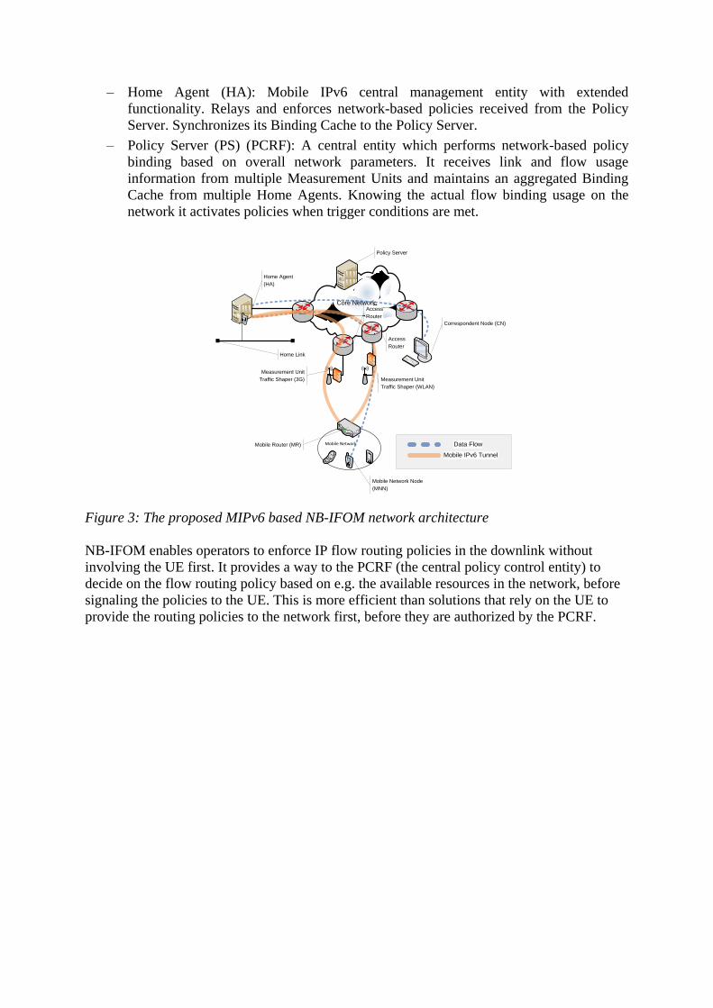
– Home Agent (HA): Mobile IPv6 central management entity with extended
functionality. Relays and enforces network-based policies received from the Policy
Server. Synchronizes its Binding Cache to the Policy Server.
– Policy Server (PS) (PCRF): A central entity which performs network-based policy
binding based on overall network parameters. It receives link and flow usage
information from multiple Measurement Units and maintains an aggregated Binding
Cache from multiple Home Agents. Knowing the actual flow binding usage on the
network it activates policies when trigger conditions are met.
Mobile Network
Core NetworkCore Network
Home Agent
(HA)
Home Link
Correspondent Node (CN)
Access
Router
Mobile Network Node
(MNN)
Mobile Router (MR) Data Flow
Mobile IPv6 Tunnel
Measurement Unit
Traffic Shaper (3G) Measurement Unit
Traffic Shaper (WLAN)
Policy Server
Access
Router
Figure 3: The proposed MIPv6 based NB-IFOM network architecture
NB-IFOM enables operators to enforce IP flow routing policies in the downlink without
involving the UE first. It provides a way to the PCRF (the central policy control entity) to
decide on the flow routing policy based on e.g. the available resources in the network, before
signaling the policies to the UE. This is more efficient than solutions that rely on the UE to
provide the routing policies to the network first, before they are authorized by the PCRF.
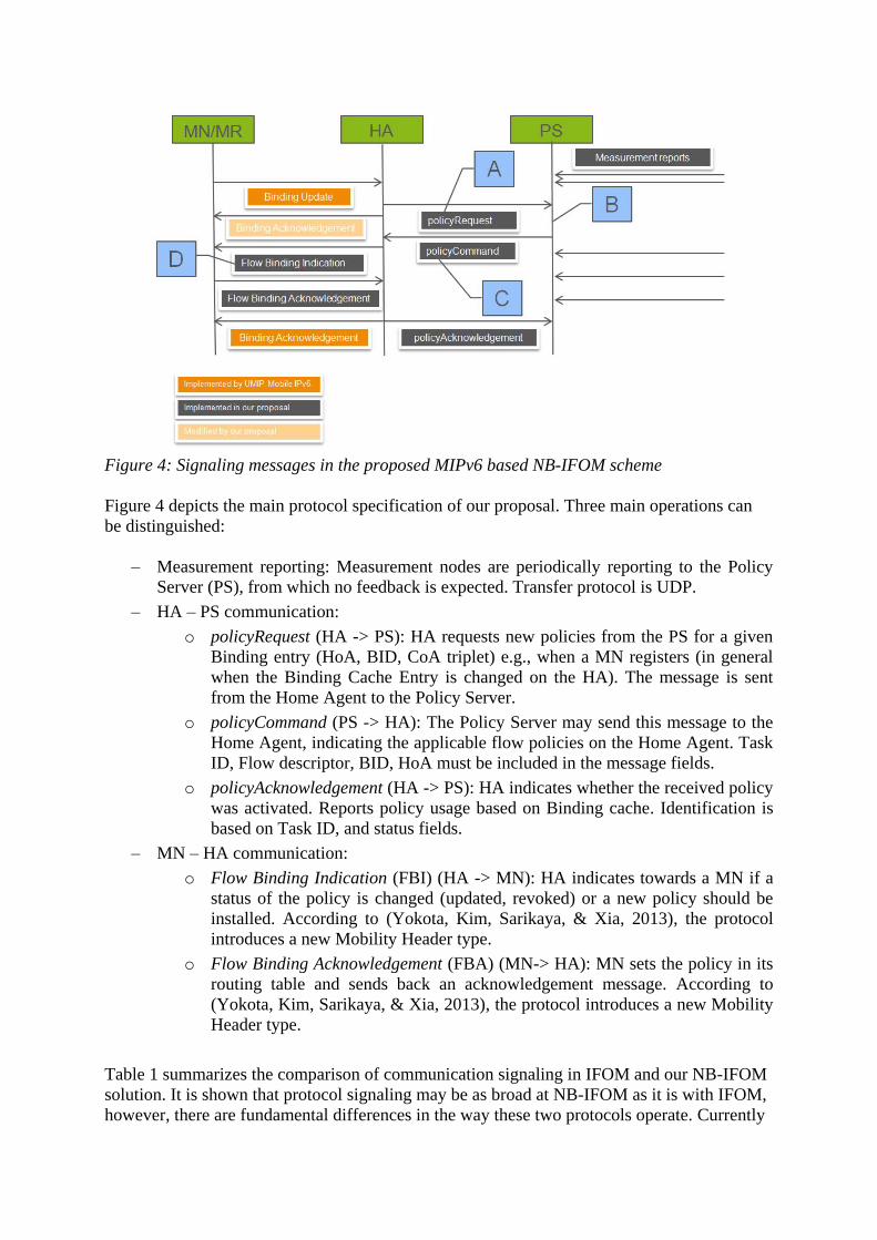
Figure 4: Signaling messages in the proposed MIPv6 based NB-IFOM scheme
Figure 4 depicts the main protocol specification of our proposal. Three main operations can
be distinguished:
– Measurement reporting: Measurement nodes are periodically reporting to the Policy
Server (PS), from which no feedback is expected. Transfer protocol is UDP.
– HA – PS communication:
o policyRequest (HA -> PS): HA requests new policies from the PS for a given
Binding entry (HoA, BID, CoA triplet) e.g., when a MN registers (in general
when the Binding Cache Entry is changed on the HA). The message is sent
from the Home Agent to the Policy Server.
o policyCommand (PS -> HA): The Policy Server may send this message to the
Home Agent, indicating the applicable flow policies on the Home Agent. Task
ID, Flow descriptor, BID, HoA must be included in the message fields.
o policyAcknowledgement (HA -> PS): HA indicates whether the received policy
was activated. Reports policy usage based on Binding cache. Identification is
based on Task ID, and status fields.
– MN – HA communication:
o Flow Binding Indication (FBI) (HA -> MN): HA indicates towards a MN if a
status of the policy is changed (updated, revoked) or a new policy should be
installed. According to (Yokota, Kim, Sarikaya, & Xia, 2013), the protocol
introduces a new Mobility Header type.
o Flow Binding Acknowledgement (FBA) (MN-> HA): MN sets the policy in its
routing table and sends back an acknowledgement message. According to
(Yokota, Kim, Sarikaya, & Xia, 2013), the protocol introduces a new Mobility
Header type.
Table 1 summarizes the comparison of communication signaling in IFOM and our NB-IFOM
solution. It is shown that protocol signaling may be as broad at NB-IFOM as it is with IFOM,
however, there are fundamental differences in the way these two protocols operate. Currently
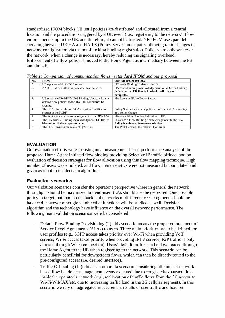
standardized IFOM blocks UE until policies are distributed and allocated from a central
location and the procedure is triggered by a UE event (i.e., registering to the network). Flow
enforcement is up to the UE, and therefore, it cannot be trusted. NB-IFOM uses parallel
signaling between UE-HA and HA-PS (Policy Server) node pairs, allowing rapid changes in
network configuration via the non-blocking binding registration. Policies are only sent over
the network, when a change is necessary, hereby reducing the signaling overhead.
Enforcement of a flow policy is moved to the Home Agent as intermediary between the PS
and the UE.
Table 1: Comparison of communication flows in standard IFOM and our proposal No. IFOM Our NB-IFOM proposal
1. UE registers with ANDSF server. UE sends Binding Update to the HA.
2. ANDSF notifies UE about updated flow policies. HA sends Binding Acknowledgement to the UE and sets up
default policy. UE flow is blocked until this step
completes.
3. UE sends a MIPv6/DSMIPv6 Binding Update with the
offered flow policies to the HA. UE BU cannot be
trusted.
HA forwards BU to Policy Server.
4. The PDN GW sends an IP-CAN session modification
request to the PCRF.
Policy Server may send a policy command to HA regarding
any policy change.
5. The PCRF sends an acknowledgement to the PDN GW. HA sends Flow Binding Indication to UE.
6. The HA sends a Binding Acknowledgment. UE flow is
blocked until this step completes.
UE sends a Flow Binding Acknowledgement to the HA.
Policy is enforced from network side.
7. The PCRF ensures the relevant QoS rules. The PCRF ensures the relevant QoS rules.
EVALUATION Our evaluation efforts were focusing on a measurement-based performance analysis of the
proposed Home Agent initiated flow binding providing Selective IP traffic offload, and on
evaluation of decision strategies for flow allocation using this flow mapping technique. High
number of users was emulated, and flow characteristics were not measured but simulated and
given as input to the decision algorithms.
Evaluation scenarios
Our validation scenarios consider the operator's perspective where in general the network
throughput should be maximized but end-user SLAs should also be respected. One possible
policy to target that load on the backhaul networks of different access segments should be
balanced, however other global objective functions will be studied as well. Decision
algorithm and the technology have influence on the overall network performance. The
following main validation scenarios were be considered:
– Default Flow Binding Provisioning (I.): this scenario means the proper enforcement of
Service Level Agreements (SLAs) to users. Three main priorities are to be defined for
user profiles (e.g., 3GPP access takes priority over Wi-Fi when providing VoIP
service; Wi-Fi access takes priority when providing IPTV service; P2P traffic is only
allowed through Wi-Fi connection). Users’ default profile can be downloaded through
the Home Agent to the UE when registering to the network. This scenario can be
particularly beneficial for downstream flows, which can then be directly routed to the
pre-configured access (i.e. desired interface).
– Traffic Offloading (II.): this is an umbrella scenario considering all kinds of network-
based flow handover management events executed due to congested/exhausted links
inside the operator’s network (e.g., reallocation of traffic flows from the 3G access to
Wi-Fi/WiMAX/etc. due to increasing traffic load in the 3G cellular segment). In this
scenario we rely on aggregated measurement results of user traffic and load on
different backhaul segments (e.g., amount of YouTube video on 3G/Wi-Fi, load on
backhaul segments of 3G/Wi-Fi). Intervention: based on static/pre-defined or dynamic
optimization functions (e.g., load on the 3G backhaul must stay below threshold) some
of the already established sessions (e.g., the YouTube flows) are moved by the Home
Agent (an updated flow descriptor is to be sent to the UE). Dynamic feedback of the
intervention could trigger 1) modifications on running operations and 2) initiation of
further operations.
– Flow Binding Revocation (III.): this scenario considers network-centric administrative
problems (e.g., when the load of an anchor node reaches a given threshold) which
could result in deletion of one or more flow bindings. Mobile nodes should be
informed that they are no longer able to use IP mobility service for the affected
flow(s). E.g., policy server collects the aggregated eNodeB load data. If the load
exceeds a given threshold, flows of mobiles handled by the affected eNodeB are
started to be moved to non-3GPP access networks. Optionally pre-defined affinities
(like VoIP is preferred to remain on 3GPP access) can also be taken into
consideration.
Implementation details and testbed environment
The main tool within this validation task is the testbed designed and implemented for
network-based IFOM performance evaluation. The proposed architecture consists of a central
Policy Server which knows the overall state of the policies. It receives measurements and
flow descriptions from various parts of the network. The Policy Server periodically checks the
predefined QoS parameters and makes decisions based on the received reports in order to
move UEs among access networks.
Mobile Network
Core NetworkCore Network
Home Agent
(HA)
Home Link
Mobile Network Node
(MNN)
Mobile Router (MR)
Policy Server
Access
Router
policyReqpolicyAck
polCmd
FlowBindingInit
FlowBindingAck
MEASUREMENTS
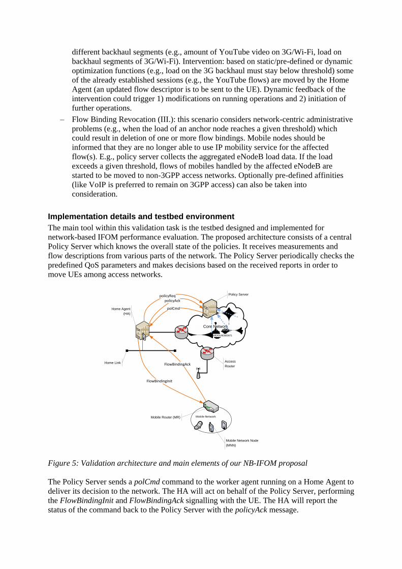
Figure 5: Validation architecture and main elements of our NB-IFOM proposal
The Policy Server sends a polCmd command to the worker agent running on a Home Agent to
deliver its decision to the network. The HA will act on behalf of the Policy Server, performing
the FlowBindingInit and FlowBindingAck signalling with the UE. The HA will report the
status of the command back to the Policy Server with the policyAck message.
It is important to mention that since the Policy Server is not part of the IPv6 mobility
framework, it has to be informed on every event related to mobility, such as new client
connection, handover event, disconnects. The HA informs the Policy Server with the
policyReq message to keep the database of the Policy Server synchronized. The Policy Server
may reply with a polCmd message to perform actions based on the changed state in mobility
and/or environment.
Since the implementation was performed on Linux, several open-source tools could be used
for validation. For traffic generation and basic functional tests we used the ping, netperf and
traceroute utilities. To dump packets and verify routing we used the tcpdump utility.
In order to measure the performance of the distribution algorithms, hundreds of flows and
multiple concurrent MNs would have to connect to the system. However, our real-life testbed
was not sufficient to present such a big number of entities and load. Due to the above
hardware limitations (i.e., only a couple of real-life UE terminals were presented) we could
only emulate big number of users by filling up the Aggregated Binding Cache with a
simulator and setting the network performance parameters with the same method. Therefore
the hybrid simulator-implementation test bed consisted of the modules depicted on Figure 6 in
the Policy Server node. It means that the functional verification was proven on the real
system, while the performance evaluation was conducted on the hybrid (real – emulated) test
network. As simulated components such as Network Monitor could not serve as a feedback to
the system, performance of some components (e.g., recursive impacts of per flow decisions)
could not be evaluated and composes a part of our future work. The hybrid structure of our
implemented Policy Server entity is depicted in Figure 6 and consists of three main functional
blocks.
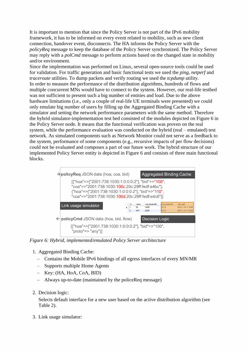
Figure 6: Hybrid, implemented/emulated Policy Server architecture
1. Aggregated Binding Cache:
– Contains the Mobile IPv6 bindings of all egress interfaces of every MN/MR
– Supports multiple Home Agents
– Key: (HA, HoA, CoA, BID)
– Always up-to-date (maintained by the policeReq message)
2. Decision logic:
Selects default interface for a new user based on the active distribution algorithm (see
Table 2).
3. Link usage simulator:
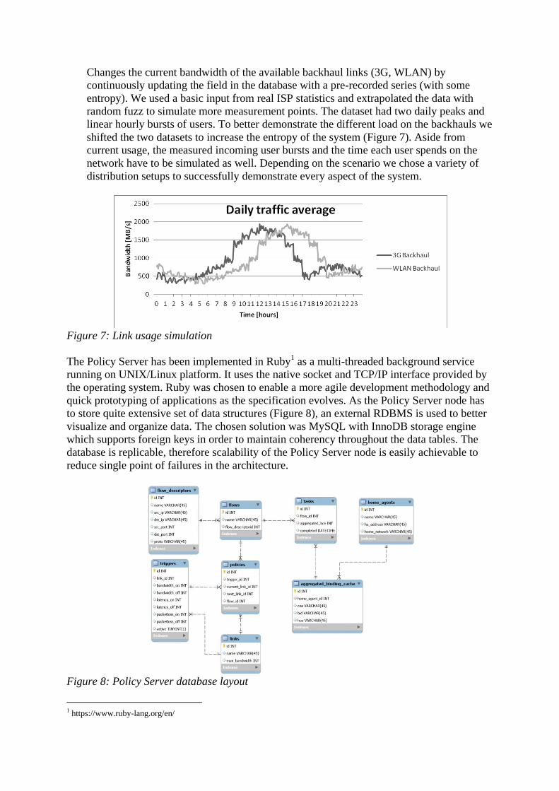
Changes the current bandwidth of the available backhaul links (3G, WLAN) by
continuously updating the field in the database with a pre-recorded series (with some
entropy). We used a basic input from real ISP statistics and extrapolated the data with
random fuzz to simulate more measurement points. The dataset had two daily peaks and
linear hourly bursts of users. To better demonstrate the different load on the backhauls we
shifted the two datasets to increase the entropy of the system (Figure 7). Aside from
current usage, the measured incoming user bursts and the time each user spends on the
network have to be simulated as well. Depending on the scenario we chose a variety of
distribution setups to successfully demonstrate every aspect of the system.
Figure 7: Link usage simulation
The Policy Server has been implemented in Ruby1 as a multi-threaded background service
running on UNIX/Linux platform. It uses the native socket and TCP/IP interface provided by
the operating system. Ruby was chosen to enable a more agile development methodology and
quick prototyping of applications as the specification evolves. As the Policy Server node has
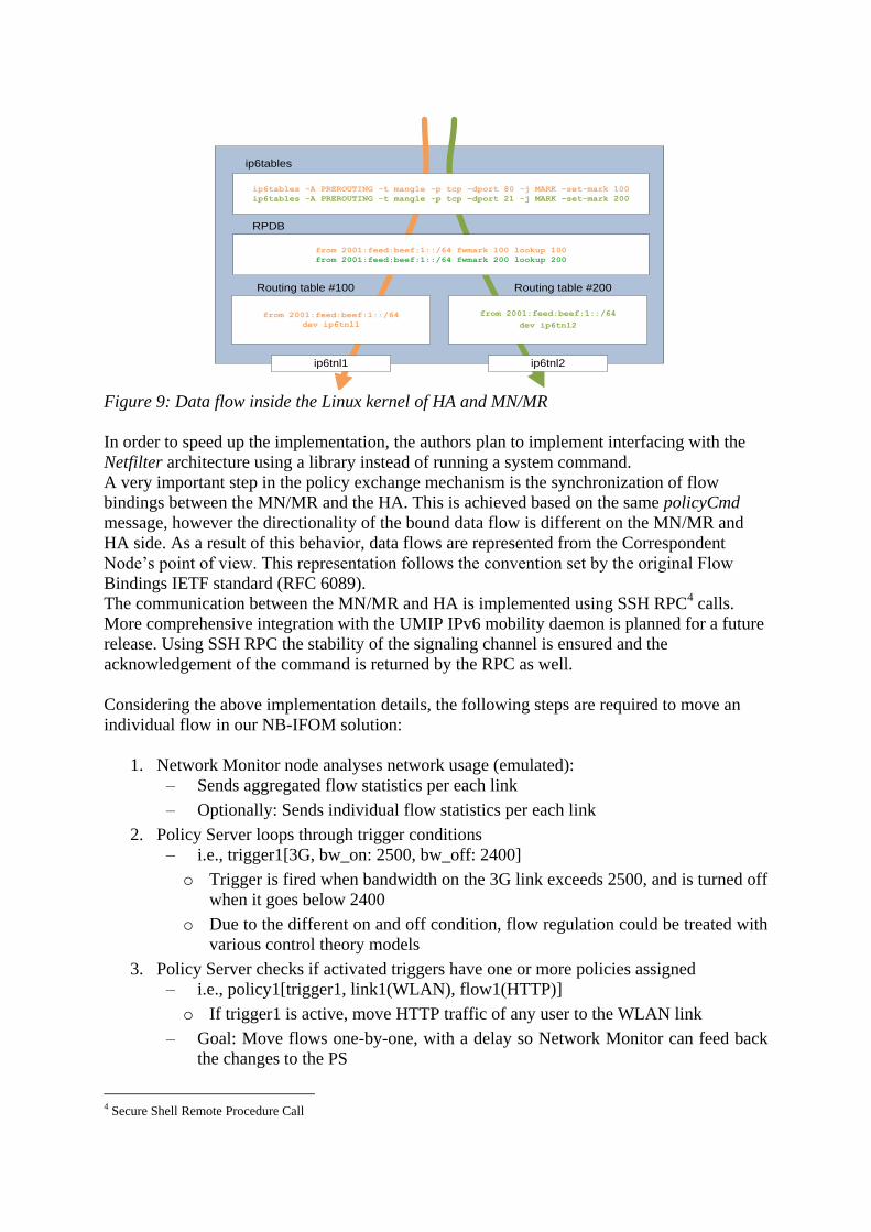
to store quite extensive set of data structures (Figure 8), an external RDBMS is used to better
visualize and organize data. The chosen solution was MySQL with InnoDB storage engine
which supports foreign keys in order to maintain coherency throughout the data tables. The
database is replicable, therefore scalability of the Policy Server node is easily achievable to
reduce single point of failures in the architecture.
Figure 8: Policy Server database layout
1 https://www.ruby-lang.org/en/

The structure of tables is depicted in Figure 8, while the details of this structure are introduced
below:
– flow_descrirtor: Used to identify a single flow based on 5-tuple information.
– flows: As flow descriptors only identify a single flow, to identify a protocol consisting
of several different flows, another abstraction layer is used.
– home_agents: This table stores administrative information for each Home Agent.
– aggregated_binding_cache: BCE entries received in the policyRequest messages are
stored here.
– tasks: Policy decisions are stored here. New entries are sent to the HA with the
policyCommand message. Acknowledgement sets the completed field.
– triggers: Trigger statements are stored here.
– policies: Applicable policies are stored in this table, filled by trigger. Moves flow from
one link to another.
– links: Stores link information.
The Home Agent implementation is based on UMIP2 MIPv6 and MCoA, and has three main
tasks: sending policyRequest messages in which the HA synchronizes its Binding Cache with
the Policy Server, maintaining flow bindings after receiving policyCommand messages, and
synchronizing the bindings with the Mobile Router. The JSON3 formatted data contains the
Home Address (HoA) and the Binding Identifier (BID) to select the egress interface of a
given UE. It also contains a list of flow descriptors to be applied for a given UE on both
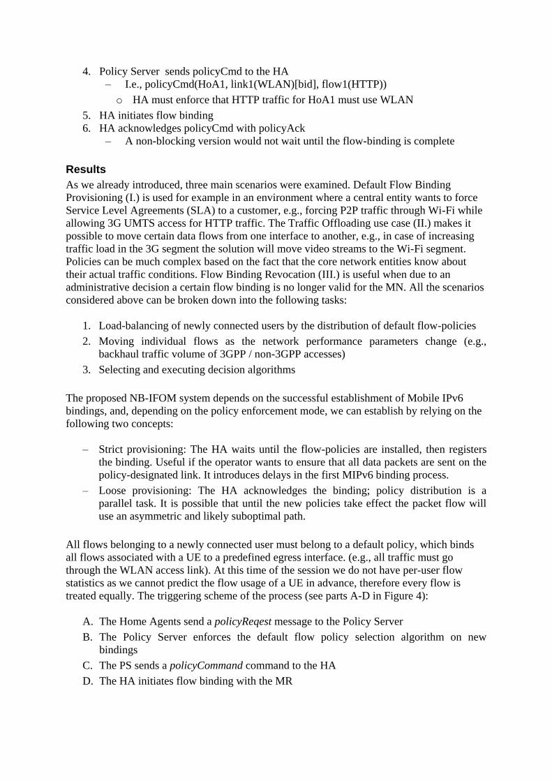
MN/MR and HA sides. The command towards the Netfilter framework of the Linux Kernel is
compiled from the message and flow binding is set via the ip6tables utility using the
following scheme:
ip6tables -A PREROUTING -t mangle –p <proto> -s <source ip> -d <dest ip> --
sport <source port> --dport <dest port> -j MARK --set-mark <bid>
Once the rules are installed the policy routing is performed using the networking subsystem of
the Linux kernel. Figure 9 describes the process:
2 UMIP MIPv6 implementation, http://www.umip.org/
3 JavaScript Object Notation, http://www.json.org/
ip6tables -A PREROUTING -t mangle -p tcp –dport 80 -j MARK –set-mark 100
ip6tables -A PREROUTING -t mangle -p tcp –dport 21 -j MARK –set-mark 200
from 2001:feed:beef:1::/64 fwmark 100 lookup 100
from 2001:feed:beef:1::/64 fwmark 200 lookup 200
from 2001:feed:beef:1::/64
dev ip6tnl1
from 2001:feed:beef:1::/64
dev ip6tnl2
ip6tnl1 ip6tnl2
ip6tables
RPDB
Routing table #100 Routing table #200
Figure 9: Data flow inside the Linux kernel of HA and MN/MR
In order to speed up the implementation, the authors plan to implement interfacing with the
Netfilter architecture using a library instead of running a system command.
A very important step in the policy exchange mechanism is the synchronization of flow
bindings between the MN/MR and the HA. This is achieved based on the same policyCmd
message, however the directionality of the bound data flow is different on the MN/MR and
HA side. As a result of this behavior, data flows are represented from the Correspondent
Node’s point of view. This representation follows the convention set by the original Flow
Bindings IETF standard (RFC 6089).
The communication between the MN/MR and HA is implemented using SSH RPC4 calls.
More comprehensive integration with the UMIP IPv6 mobility daemon is planned for a future
release. Using SSH RPC the stability of the signaling channel is ensured and the
acknowledgement of the command is returned by the RPC as well.
Considering the above implementation details, the following steps are required to move an
individual flow in our NB-IFOM solution:
1. Network Monitor node analyses network usage (emulated):
– Sends aggregated flow statistics per each link
– Optionally: Sends individual flow statistics per each link
2. Policy Server loops through trigger conditions
– i.e., trigger1[3G, bw_on: 2500, bw_off: 2400]
o Trigger is fired when bandwidth on the 3G link exceeds 2500, and is turned off
when it goes below 2400
o Due to the different on and off condition, flow regulation could be treated with
various control theory models
3. Policy Server checks if activated triggers have one or more policies assigned
– i.e., policy1[trigger1, link1(WLAN), flow1(HTTP)]
o If trigger1 is active, move HTTP traffic of any user to the WLAN link
– Goal: Move flows one-by-one, with a delay so Network Monitor can feed back
the changes to the PS
4 Secure Shell Remote Procedure Call
4. Policy Server sends policyCmd to the HA
– I.e., policyCmd(HoA1, link1(WLAN)[bid], flow1(HTTP))
o HA must enforce that HTTP traffic for HoA1 must use WLAN
5. HA initiates flow binding
6. HA acknowledges policyCmd with policyAck
– A non-blocking version would not wait until the flow-binding is complete
Results
As we already introduced, three main scenarios were examined. Default Flow Binding
Provisioning (I.) is used for example in an environment where a central entity wants to force
Service Level Agreements (SLA) to a customer, e.g., forcing P2P traffic through Wi-Fi while
allowing 3G UMTS access for HTTP traffic. The Traffic Offloading use case (II.) makes it
possible to move certain data flows from one interface to another, e.g., in case of increasing
traffic load in the 3G segment the solution will move video streams to the Wi-Fi segment.
Policies can be much complex based on the fact that the core network entities know about
their actual traffic conditions. Flow Binding Revocation (III.) is useful when due to an
administrative decision a certain flow binding is no longer valid for the MN. All the scenarios
considered above can be broken down into the following tasks:
1. Load-balancing of newly connected users by the distribution of default flow-policies
2. Moving individual flows as the network performance parameters change (e.g.,
backhaul traffic volume of 3GPP / non-3GPP accesses)
3. Selecting and executing decision algorithms
The proposed NB-IFOM system depends on the successful establishment of Mobile IPv6
bindings, and, depending on the policy enforcement mode, we can establish by relying on the
following two concepts:
– Strict provisioning: The HA waits until the flow-policies are installed, then registers
the binding. Useful if the operator wants to ensure that all data packets are sent on the
policy-designated link. It introduces delays in the first MIPv6 binding process.
– Loose provisioning: The HA acknowledges the binding; policy distribution is a
parallel task. It is possible that until the new policies take effect the packet flow will
use an asymmetric and likely suboptimal path.
All flows belonging to a newly connected user must belong to a default policy, which binds
all flows associated with a UE to a predefined egress interface. (e.g., all traffic must go
through the WLAN access link). At this time of the session we do not have per-user flow
statistics as we cannot predict the flow usage of a UE in advance, therefore every flow is
treated equally. The triggering scheme of the process (see parts A-D in Figure 4):
A. The Home Agents send a policyReqest message to the Policy Server
B. The Policy Server enforces the default flow policy selection algorithm on new
bindings
C. The PS sends a policyCommand command to the HA
D. The HA initiates flow binding with the MR
The distribution policy in the Policy Server for delivering default flow policies is static. (i.e.,
set in a configuration file). Table 2 summarizes the implemented load-balancing techniques
with respect to the overall stability of the network. The objective function of the methodology
is to prevent the use of policies (Note: Policies will only be applied when the traffic
parameters and QoS inside the backhaul and the core networks are suboptimal), by keeping
the load distribution stable. This performance indicator does not consider rapid changes in
existing data flows.
Table 2: The implemented decision algorithms Distribution
algorithm
Input
argument
Remarks Results
Round-robin - Flows are distributed among available
uplinks evenly.
Good for Best Effort QoS. Uneven
flow bandwidth distribution may
result in policy reallocation.
Least Used current
bandwidth
Dynamic selection based on the recently
used link
Better than RR and Overflow
Lowest
latency
current
latency
Dynamic selection based on the actual
latencies on the links
Better than RR and Overflow
Overflow current
bandwidth
The algorithm waits until one of the links
become full, allowing network policy
events to be triggered before utilizing all
available media.
This method is the worst case.
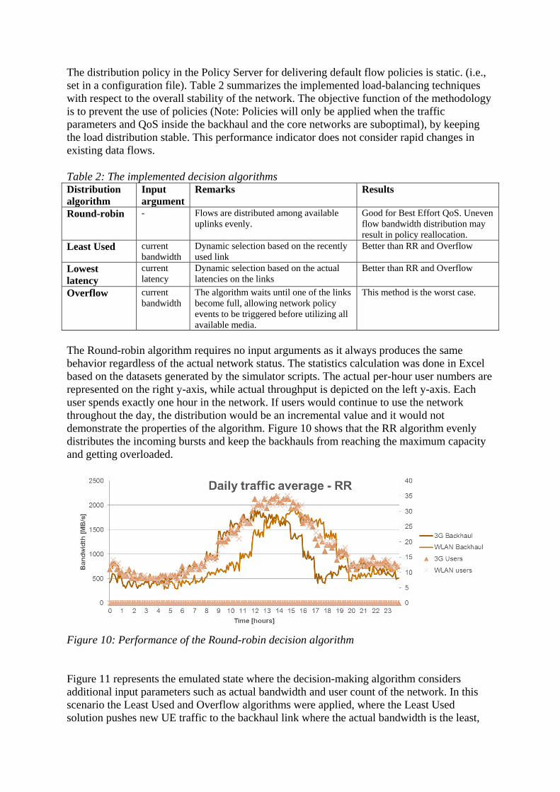
The Round-robin algorithm requires no input arguments as it always produces the same
behavior regardless of the actual network status. The statistics calculation was done in Excel
based on the datasets generated by the simulator scripts. The actual per-hour user numbers are
represented on the right y-axis, while actual throughput is depicted on the left y-axis. Each
user spends exactly one hour in the network. If users would continue to use the network
throughout the day, the distribution would be an incremental value and it would not
demonstrate the properties of the algorithm. Figure 10 shows that the RR algorithm evenly
distributes the incoming bursts and keep the backhauls from reaching the maximum capacity
and getting overloaded.
Figure 10: Performance of the Round-robin decision algorithm
Figure 11 represents the emulated state where the decision-making algorithm considers
additional input parameters such as actual bandwidth and user count of the network. In this
scenario the Least Used and Overflow algorithms were applied, where the Least Used
solution pushes new UE traffic to the backhaul link where the actual bandwidth is the least,
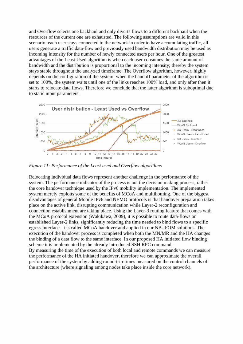
and Overflow selects one backhaul and only diverts flows to a different backhaul when the
resources of the current one are exhausted. The following assumptions are valid in this
scenario: each user stays connected to the network in order to have accumulating traffic, all
users generate a traffic data-flow and previously used bandwidth distribution may be used as
incoming intensity for the number of newly connected users per hour. One of the greatest
advantages of the Least Used algorithm is when each user consumes the same amount of
bandwidth and the distribution is proportional to the incoming intensity; thereby the system
stays stable throughout the analyzed timeframe. The Overflow algorithm, however, highly
depends on the configuration of the system: when the handoff parameter of the algorithm is
set to 100%, the system waits until one of the links reaches 100% load, and only after then it
starts to relocate data flows. Therefore we conclude that the latter algorithm is suboptimal due
to static input parameters.
Figure 11: Performance of the Least used and Overflow algorithms
Relocating individual data flows represent another challenge in the performance of the
system. The performance indicator of the process is not the decision making process, rather
the core handover technique used by the IPv6 mobility implementation. The implemented
system merely exploits some of the benefits of MCoA and multihoming. One of the biggest
disadvantages of general Mobile IPv6 and NEMO protocols is that handover preparation takes
place on the active link, disrupting communication while Layer-2 reconfiguration and
connection establishment are taking place. Using the Layer-3 routing feature that comes with
the MCoA protocol extension (Wakikawa, 2009), it is possible to route data-flows on
established Layer-2 links, significantly reducing the time needed to bind flows to a specific
egress interface. It is called MCoA handover and applied in our NB-IFOM solutions. The
execution of the handover process is completed when both the MN/MR and the HA changes
the binding of a data flow to the same interface. In our proposed HA initiated flow binding
scheme it is implemented by the already introduced SSH RPC command.
By measuring the time of the execution of both local and remote commands we can measure
the performance of the HA initiated handover, therefore we can approximate the overall
performance of the system by adding round-trip-times measured on the control channels of
the architecture (where signaling among nodes take place inside the core network).
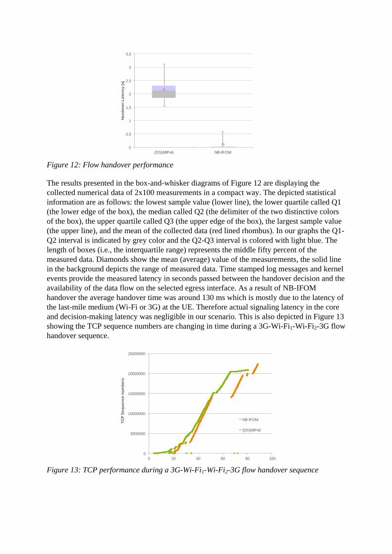
Figure 12: Flow handover performance
The results presented in the box-and-whisker diagrams of Figure 12 are displaying the
collected numerical data of 2x100 measurements in a compact way. The depicted statistical
information are as follows: the lowest sample value (lower line), the lower quartile called Q1
(the lower edge of the box), the median called Q2 (the delimiter of the two distinctive colors
of the box), the upper quartile called Q3 (the upper edge of the box), the largest sample value
(the upper line), and the mean of the collected data (red lined rhombus). In our graphs the Q1-
Q2 interval is indicated by grey color and the Q2-Q3 interval is colored with light blue. The
length of boxes (i.e., the interquartile range) represents the middle fifty percent of the
measured data. Diamonds show the mean (average) value of the measurements, the solid line
in the background depicts the range of measured data. Time stamped log messages and kernel
events provide the measured latency in seconds passed between the handover decision and the
availability of the data flow on the selected egress interface. As a result of NB-IFOM
handover the average handover time was around 130 ms which is mostly due to the latency of
the last-mile medium (Wi-Fi or 3G) at the UE. Therefore actual signaling latency in the core
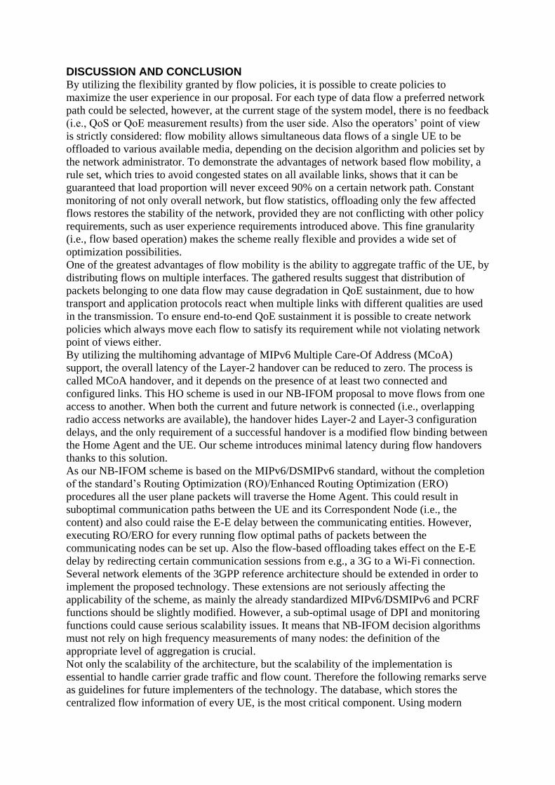
and decision-making latency was negligible in our scenario. This is also depicted in Figure 13
showing the TCP sequence numbers are changing in time during a 3G-Wi-Fi1-Wi-Fi2-3G flow
handover sequence.
Figure 13: TCP performance during a 3G-Wi-Fi1-Wi-Fi2-3G flow handover sequence
0
0,5
1
1,5
2
2,5
3
3,5
(DS)MIPv6 NB-IFOM
Ha
nd
ove
r L
ate
ncy [
s]
0
5000000
10000000
15000000
20000000
25000000
0 20 40 60 80 100
TC
P S
eq
ue
nce
nu
mb
ers
NB-IFOM
(DS)MIPv6
DISCUSSION AND CONCLUSION By utilizing the flexibility granted by flow policies, it is possible to create policies to
maximize the user experience in our proposal. For each type of data flow a preferred network
path could be selected, however, at the current stage of the system model, there is no feedback
(i.e., QoS or QoE measurement results) from the user side. Also the operators’ point of view
is strictly considered: flow mobility allows simultaneous data flows of a single UE to be
offloaded to various available media, depending on the decision algorithm and policies set by
the network administrator. To demonstrate the advantages of network based flow mobility, a
rule set, which tries to avoid congested states on all available links, shows that it can be
guaranteed that load proportion will never exceed 90% on a certain network path. Constant
monitoring of not only overall network, but flow statistics, offloading only the few affected
flows restores the stability of the network, provided they are not conflicting with other policy
requirements, such as user experience requirements introduced above. This fine granularity
(i.e., flow based operation) makes the scheme really flexible and provides a wide set of
optimization possibilities.
One of the greatest advantages of flow mobility is the ability to aggregate traffic of the UE, by
distributing flows on multiple interfaces. The gathered results suggest that distribution of
packets belonging to one data flow may cause degradation in QoE sustainment, due to how
transport and application protocols react when multiple links with different qualities are used
in the transmission. To ensure end-to-end QoE sustainment it is possible to create network
policies which always move each flow to satisfy its requirement while not violating network
point of views either.
By utilizing the multihoming advantage of MIPv6 Multiple Care-Of Address (MCoA)
support, the overall latency of the Layer-2 handover can be reduced to zero. The process is
called MCoA handover, and it depends on the presence of at least two connected and
configured links. This HO scheme is used in our NB-IFOM proposal to move flows from one
access to another. When both the current and future network is connected (i.e., overlapping
radio access networks are available), the handover hides Layer-2 and Layer-3 configuration
delays, and the only requirement of a successful handover is a modified flow binding between
the Home Agent and the UE. Our scheme introduces minimal latency during flow handovers
thanks to this solution.
As our NB-IFOM scheme is based on the MIPv6/DSMIPv6 standard, without the completion
of the standard’s Routing Optimization (RO)/Enhanced Routing Optimization (ERO)
procedures all the user plane packets will traverse the Home Agent. This could result in
suboptimal communication paths between the UE and its Correspondent Node (i.e., the
content) and also could raise the E-E delay between the communicating entities. However,
executing RO/ERO for every running flow optimal paths of packets between the
communicating nodes can be set up. Also the flow-based offloading takes effect on the E-E
delay by redirecting certain communication sessions from e.g., a 3G to a Wi-Fi connection.
Several network elements of the 3GPP reference architecture should be extended in order to
implement the proposed technology. These extensions are not seriously affecting the
applicability of the scheme, as mainly the already standardized MIPv6/DSMIPv6 and PCRF
functions should be slightly modified. However, a sub-optimal usage of DPI and monitoring
functions could cause serious scalability issues. It means that NB-IFOM decision algorithms
must not rely on high frequency measurements of many nodes: the definition of the
appropriate level of aggregation is crucial.
Not only the scalability of the architecture, but the scalability of the implementation is
essential to handle carrier grade traffic and flow count. Therefore the following remarks serve
as guidelines for future implementers of the technology. The database, which stores the
centralized flow information of every UE, is the most critical component. Using modern
relational database management systems such as Oracle, MySQL, etc. the ability to
horizontally or vertically scale the database backend over multiple nodes is available at hand,
and it single handedly eliminates the problem of single point-of-failure and load-balancing.
The bottleneck of the actual and future implementations would be the Home Agent. Currently
HA implementations are not ready to serve large quantities of UEs and they are quite
unstable; hence the lack of large-scale performance tests of our solution is quite substantial. In
order to eliminate the scalability a problem of the Home Agent, a new implementation is
required which scales well with recent features of the kernel of the operating system. One of
the promising solutions is the MIP6D-NG project (Takács & Bokor, 2013) which implements
XFRM tunneling inside the Linux kernel, speeding up the internal processes of the mobility
component. To overcome the single point-of-failure issue, Global HA to HA communication
should also be implemented in the future which allow multiple Home Agent nodes to operate
for the same UE domain.
ACKNOWLEDGEMENT
The publication was supported by the TÁMOP-4.2.2.C-11/1/KONV-2012-0001 project. The
project has been supported by the European Union, co-financed by the European Social Fund.
The publication also received funding from the European CELTIC project CP7-011
MEVICO, although the views expressed are those of the authors and do not necessarily
represent the project. The authors would like to acknowledge the contributions of their
colleagues in both projects, especially to Zoltán Faigl for his valuable comments and remarks.
REFERENCES
3GPP TR 23.829. (Sept. 2010). Local IP Access and Selected IP Traffic Offload, Release 10,
V1.3.0. 3GPP Technical Report.
3GPP TR 23.861. (February 2010). Multi access PDN connectivity and IP flow mobility,
Release 9. 3GPP Technical Report.
3GPP TS 22.220. (June, 2011). Service requirements for Home Node B (HNB) and Home
eNode B (HeNB), Release 10. 3GPP Technical Specification.
3GPP TS 23.060. (June 2011). Technical Specification, “General Packet Radio Service
(GPRS); Service description”, Stage 2, Release 10. 3GPP Technical Specification.
3GPP TS 23.261. (September 2010). IP flow mobility and seamless Wireless Local Area
Network (WLAN) offload, Stage 2, Release 10. 3GPP Technical Specification.
3GPP TS 23.327. (March, 2011). Mobility between 3GPP-Wireless Local Area Network
(WLAN) interworking and 3GPP systems, V10.0.0. 3GPP Technical Specification.
3GPP TS 23.401 V10.4.0. (June 2011). General Packet Radio Service (GPRS) enhancements
for Evolved Universal Terrestrial Radio Access Network (E-UTRAN) access, Release
10. 3GPP Technical Specification.
3GPP TS 23.402. (June, 2011). Architecture enhancements for non-3GPP accesses, Release
10, V10.4.0. 3GPP Technical Specification.
De La Oliva, A., Bernardos, C. J., Calderon, M., Melia, T., & Zuniga, J. (2011). IP flow
mobility: smart traffic offload for future wireless networks. IEEE Communications
Magazine, 49(10), 124-132.
IEEE. (Jan. 2009). IEEE Standard for Local and metropolitan area networks- Part 21: Media
Independent Handover. IEEE Std 802.21-2008.
Perkins, C., Johnson, D., & Arkko, J. (2011, July). Mobility Support in IPv6. IETF RFC
6275.
Soliman, H. (. (2009, June). Mobile IPv6 Support for Dual Stack Hosts and Routers. IETF
RFC 5555.

Takács, A. T., & Bokor, L. (2013). A distributed dynamic mobility architecture with integral
cross-layered and context-aware interface for reliable provision of high bitrate mhealth
services. Lecture Notes of the Institute for Computer Sciences, 61, 369-379.
Taleb, T., Samdanis, K., & Schmid, S. (2011). DNS-Based Solution for Operator Control of
Selected IP Traffic Offload. IEEE International Conference on Communications
(ICC), (pp. 1-5).
Tran, M. T., Youn-Hee, H., Hyon-Young, C., & Hong, Y. G. (April 2011). A Design of
Network-based Flow Mobility based on Proxy Mobile IPv6. (pp. 373–378). IEEE
Conference on Computer Communications Workshops (INFOCOM WKSHPS).
Tsirtsis, G., Soliman, H., Montavont, N., Giaretta, G., & Kuladinithi, K. (2011, January).
Flow Bindings in Mobile IPv6 and Network Mobility (NEMO) Basic Support. IETF
RFC 6089.
Wakikawa, R. e. (2009, October). Multiple Care-of Addresses Registration. IETF RFC 5648.
Wang, Q., Atkinson, R., Cromar, C., & Dunlop, J. (April 2007). Hybrid User- and Network-
Initiated Flow Handoff Support for Multihomed Mobile Hosts. (pp. 748–752). IEEE
65th Vehicular Technology Conference, VTC2007-Spring.
Yokota, H., Kim, D., Sarikaya, B., & Xia, F. (2013, August). Home Agent Initiated Flow
Binding for Mobile IPv6. IETF I-D. draft-yokota-mext-ha-init-flow-binding-06.